EP2976754B1 - Electronic lock with selectable power sources - Google Patents
Electronic lock with selectable power sources Download PDFInfo
- Publication number
- EP2976754B1 EP2976754B1 EP14724822.3A EP14724822A EP2976754B1 EP 2976754 B1 EP2976754 B1 EP 2976754B1 EP 14724822 A EP14724822 A EP 14724822A EP 2976754 B1 EP2976754 B1 EP 2976754B1
- Authority
- EP
- European Patent Office
- Prior art keywords
- energy
- lock core
- harvester
- actuator
- removable lock
- Prior art date
- Legal status (The legal status is an assumption and is not a legal conclusion. Google has not performed a legal analysis and makes no representation as to the accuracy of the status listed.)
- Active
Links
Images
Classifications
-
- G—PHYSICS
- G07—CHECKING-DEVICES
- G07C—TIME OR ATTENDANCE REGISTERS; REGISTERING OR INDICATING THE WORKING OF MACHINES; GENERATING RANDOM NUMBERS; VOTING OR LOTTERY APPARATUS; ARRANGEMENTS, SYSTEMS OR APPARATUS FOR CHECKING NOT PROVIDED FOR ELSEWHERE
- G07C9/00—Individual registration on entry or exit
- G07C9/20—Individual registration on entry or exit involving the use of a pass
-
- G—PHYSICS
- G07—CHECKING-DEVICES
- G07C—TIME OR ATTENDANCE REGISTERS; REGISTERING OR INDICATING THE WORKING OF MACHINES; GENERATING RANDOM NUMBERS; VOTING OR LOTTERY APPARATUS; ARRANGEMENTS, SYSTEMS OR APPARATUS FOR CHECKING NOT PROVIDED FOR ELSEWHERE
- G07C9/00—Individual registration on entry or exit
- G07C9/00174—Electronically operated locks; Circuits therefor; Nonmechanical keys therefor, e.g. passive or active electrical keys or other data carriers without mechanical keys
-
- H—ELECTRICITY
- H04—ELECTRIC COMMUNICATION TECHNIQUE
- H04W—WIRELESS COMMUNICATION NETWORKS
- H04W4/00—Services specially adapted for wireless communication networks; Facilities therefor
- H04W4/80—Services using short range communication, e.g. near-field communication [NFC], radio-frequency identification [RFID] or low energy communication
-
- G—PHYSICS
- G07—CHECKING-DEVICES
- G07C—TIME OR ATTENDANCE REGISTERS; REGISTERING OR INDICATING THE WORKING OF MACHINES; GENERATING RANDOM NUMBERS; VOTING OR LOTTERY APPARATUS; ARRANGEMENTS, SYSTEMS OR APPARATUS FOR CHECKING NOT PROVIDED FOR ELSEWHERE
- G07C9/00—Individual registration on entry or exit
- G07C9/00174—Electronically operated locks; Circuits therefor; Nonmechanical keys therefor, e.g. passive or active electrical keys or other data carriers without mechanical keys
- G07C2009/00634—Power supply for the lock
-
- G—PHYSICS
- G07—CHECKING-DEVICES
- G07C—TIME OR ATTENDANCE REGISTERS; REGISTERING OR INDICATING THE WORKING OF MACHINES; GENERATING RANDOM NUMBERS; VOTING OR LOTTERY APPARATUS; ARRANGEMENTS, SYSTEMS OR APPARATUS FOR CHECKING NOT PROVIDED FOR ELSEWHERE
- G07C9/00—Individual registration on entry or exit
- G07C9/00174—Electronically operated locks; Circuits therefor; Nonmechanical keys therefor, e.g. passive or active electrical keys or other data carriers without mechanical keys
- G07C2009/00634—Power supply for the lock
- G07C2009/00642—Power supply for the lock by battery
-
- G—PHYSICS
- G07—CHECKING-DEVICES
- G07C—TIME OR ATTENDANCE REGISTERS; REGISTERING OR INDICATING THE WORKING OF MACHINES; GENERATING RANDOM NUMBERS; VOTING OR LOTTERY APPARATUS; ARRANGEMENTS, SYSTEMS OR APPARATUS FOR CHECKING NOT PROVIDED FOR ELSEWHERE
- G07C9/00—Individual registration on entry or exit
- G07C9/00174—Electronically operated locks; Circuits therefor; Nonmechanical keys therefor, e.g. passive or active electrical keys or other data carriers without mechanical keys
- G07C2009/00753—Electronically operated locks; Circuits therefor; Nonmechanical keys therefor, e.g. passive or active electrical keys or other data carriers without mechanical keys operated by active electrical keys
- G07C2009/00769—Electronically operated locks; Circuits therefor; Nonmechanical keys therefor, e.g. passive or active electrical keys or other data carriers without mechanical keys operated by active electrical keys with data transmission performed by wireless means
Definitions
- Lock cores are prevalent in use.
- the small format interchangeable core (SFIC) is an example of such a mechanical removable lock core.
- Lock cores may be used in a number of applications, such as doors, cabinets, and other entities or devices that have an ability to accept a mechanical removable lock core.
- Traditional lock cores use a first key for standard operation by users and a second key for operation by, e.g., facility security managers. The second key may be used to remove the lock core.
- Some lock cores utilize an electromechanical actuator within the core that is operable through the use of an electronic key.
- Use of an electromechanical core and electronic key provides for convenience in terms of allowing a reprogramming of user access remotely (e.g., rekeying) without a need to physically remove a core. However, a user is still required to carry a key.
- Keys are subject to being lost or broken, which may further represent a security risk and/or administrative inconvenience to replace a key.
- Exemplary locks are described in US 2012/108168 , EP1564689 , DE102009013650 and US6000609 .
- the present invention is directed to a removable lock core as claimed in claim 1. Further advantageous arrangements of the present invention are described in the dependent claims 2-6.
- a lock core may be self-powered, and a state of the lock (e.g., locked or unlocked) may be determined based on a wireless communication.
- a user may operate the lock core based on a device that the user normally has in her possession, such as a mobile phone.
- the lock may include an internal power source for normal operations, as well as a rechargeable storage element which may allow the lock to be powered from one or more external sources (e.g., external wireless sources). Powering the lock from an external source may be used for management or emergency purposes, or may be performed to remove the lock.
- aspects of the disclosure may be applied in connection with an electromechanical replaceable lock core, a standard electronic lock, etc.
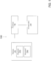
- FIG. 1 an exemplary computing system 100 is shown.
- the system 100 is shown as including a memory 102.
- the memory 102 may store executable instructions.
- the executable instructions may be stored or organized in any manner and at any level of abstraction, such as in connection with one or more processes, routines, procedures, methods, etc. As an example, at least a portion of the instructions are shown in FIG. 1 as being associated with a first program 104a and a second program 104b.
- the instructions stored in the memory 102 may be executed by one or more processors, such as a processor 106.
- the processor 106 may be coupled to one or more input/output (I/O) devices 108.
- the I/O device(s) 108 may include one or more of a keyboard or keypad, a touchscreen or touch panel, a display screen, a microphone, a speaker, a mouse, a button, a remote control, a joystick, a printer, a telephone or mobile device (e.g., a smartphone), etc.
- the I/O device(s) 108 may be configured to provide an interface to allow a user to interact with the system 100.
- the system 100 is illustrative. In some embodiments, one or more of the entities may be optional. In some embodiments, additional entities not shown may be included. For example, in some embodiments the system 100 may be associated with one or more networks. In some embodiments, the entities may be arranged or organized in a manner different from what is shown in FIG. 1 . One or more of the entities shown in FIG. 1 may be associated with one or more of the devices or entities described herein.
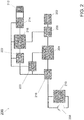
- FIG. 2 illustrates an exemplary circuit architecture 200.
- the circuit 200 may be used to selectively power a lock or lock core using an internal power source or an external power source.
- the external power source may include a wireless power source, and is a mobile phone.
- the external power source may include a thermal source or a light source.
- the circuit 200 may include an actuator 202.
- the actuator 202 may correspond to an electromechanical device.
- the actuator 202 may receive power or energy from an energy store 204 by way of a controller 206.
- the actuator 202 may be responsible for controlling a state (e.g., locked or unlocked) of a lock.
- the actuator 202 may include a motor or motor drive components.
- the controller 206 may ensure that the actuator 202 is placed in an appropriate state or position.
- the energy store 204 may directly power the controller 206 and actuator 202.
- the energy store 204 may be driven by an internal power source or an external power source.
- the energy store 204 may include one or more super-capacitors or capacitors featuring relatively minimal resistance.
- the energy store 204 may include lower quality or higher-resistance capacitors.
- a design decision may be made regarding a capacity or responsiveness of the energy store 204 relative to a size or type of the components used. For example, smaller components (e.g., capacitors) may be used in embodiments where a lock core is implemented using a small form factor, which may tend to increase response times.
- components may be selected or sized in order to reduce or minimize power draw or power consumption.
- components may be selected to provide for a small idle or sleep current.
- a sleep current of approximately 200nA-3uA may be provided, or a sleep current within an order of magnitude of 1uA.
- the internal power source may include a primary energy storage element.
- the primary energy storage element includes a battery 208.
- the battery 208 may power a real-time clock (RTC) 210.
- the RTC 210 may be used for data logging purposes or may be used to determine when a particular user should be able to change the state of the lock.
- the RTC 210 may be implemented using the MCU 216 to reduce the space required by the circuit 200.
- the external power source which may be illustratively represented by a (coupling) coil 212 in FIG. 2 , is associated with an external device, such as a wireless device that a user typically has in her possession.
- the wireless device comprises a mobile phone (e.g., a smartphone).
- Power provided by the wireless device 212 may be obtained by a harvester 214 for potential use or collection by the energy store 204. Power transfer may also be enabled through use of propagating waves using either a coil or standard antenna as a physical interface.
- the circuit 200 may include a processing device, such as a PIC or MSP-class device, a digital signal processor, or microcontroller unit (MCU) 216.
- the MCU 216 may correspond to the processor 106 and/or the memory 102 of FIG. 1 .
- the MCU 216 may determine which power source (e.g., internal power or external power) should be used by the energy store 204 to power and control the controller 206 and/or the actuator 202.
- the MCU 216 may also be used to control the actuator 202 through analog or digital ports.
- the MCU 216 may select the harvester 214 to provide energy to the actuator 202 when the primary energy storage element (e.g., the battery 208) provides energy in an amount less than a threshold or is depleted.
- the primary energy storage element e.g., the battery 208
- temperature may dictate selection of the harvester 214. For example, when it is cold outside, the battery 208 might not be able to provide sufficient energy. Energy provided to the actuator 202 by the harvester 214 may be used to remove a lock core so that the battery 208 can be replaced.
- the circuit 200 may include one or more switches, such as switches 218, 220, and 222.
- the switch 218 may be used to selectively provide power from the internal power source or battery 208 to the energy store 204.
- the switch 220 may be used to selectively provide power from the external power source 212, via the harvester 214, to the energy store 204.
- the switch 222 may be used to selectively power the MCU 216 from the external power source 212 via the harvester 214, which may be used, for example, when the battery 208 is depleted.
- the circuit 200 is illustrative. In some embodiments, one or more of the entities may be optional (e.g., RTC 210). In some embodiments, additional entities not shown may be included.
- the circuit may include a transceiver (e.g., a wireless transceiver) that may be configured to engage in one or more communications (e.g., one or more encrypted communications) with one or more devices (e.g., a mobile device or phone).
- the entities may be arranged or organized in a manner different from what is shown in FIG. 2 .
- the lock core may be a standalone unit that may be self-powered, with an ability to harvest energy from an external source.
- the external source may be the user's mobile device.
- the harvesting may occur using one or more techniques or schemes. For example, the harvesting may be based on a near field communication (NFC) or operate at standard ISM frequencies (e.g. 900 MHz, 2.4 GHz etc.). The harvesting may allow the lock core to be removed, potentially in connection with an emergency.
- NFC near field communication
- ISM frequencies e.g. 900 MHz, 2.4 GHz etc.
- the lock core may maintain a data log or trail.
- the data may be accessed or viewed by a device or location that is remote from the lock core.
- the lock core may engage in communications (e.g., encrypted communications) with one or more devices or entities.
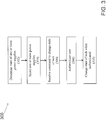
- the method 300 may be executed by one or more systems, circuits, devices, or components, such as those described herein.
- the method 300 may be used to power an actuator (e.g., actuator 202 of FIG. 2 ) that may be used to select a state for a lock, wherein the power may be derived from an internal power source or an external power source.
- an actuator e.g., actuator 202 of FIG. 2
- the power may be derived from an internal power source or an external power source.
- a determination may be made regarding a state of one or more power supplies. For example, a determination may be made whether power provided by an internal power supply is available in an amount greater than a threshold or in an amount that is greater than an external power supply.
- one or more power supplies to use may be selected. For example, if the determination of block 302 indicates that the internal power supply is capable of providing power in the amount greater than the threshold then the internal power supply may be used. Otherwise, an external power supply may be used if such external power supply is available. External power may be harvested from a mobile phone associated with a user. In some arrangements not in accordance with the present invention, external power may be harvested based on mechanical energy (e.g., a push to charge type of lock).
- a command may be received to change a state of the lock. For example, if the lock is in a locked state, the command of block 306 may direct the lock to unlock.
- the command may be received from a device associated with a user, such as a mobile device or a phone.
- the command may include one or more credentials or identifiers that may indicate whether the user has been provided access rights to control or change the state of the lock.
- the user may be authenticated. For example, if the command of block 306 includes one or more credentials, the one or more credentials may be compared to a listing of authorized users to determine whether the command should allow the state of the lock to change.
- the lock may change state in block 310.
- an entry in a data log may be generated. The entry may specify one or more of the date and time that the command for changing the state of the lock was received, whether the state of the lock was changed, the state that the lock was changed from or to, and an identity of the user or a device associated with the user.
- the method 300 is illustrative. In some embodiments, one or more of the blocks or operations (or portions thereof) may be optional. In some embodiments, additional operations not shown may be included. In some embodiments, the operations may execute in an order or sequence different from what is shown.
- access to a lock or lock core may be a function of an amount of energy provided by a primary energy storage element (e.g., a battery) and a level associated with a user attempting to access the lock/lock core. For example, if an amount of energy provided by the primary energy storage element is less than a threshold, a general user might be precluded access, such that only "supervisory-level" users can use the battery for normal operation down to a certain battery level or certain number of operations, followed by certain authorized keys being able to open and/or remove the lock using, e.g., inductive coupling.
- a primary energy storage element e.g., a battery
- Embodiments of the disclosure may be tied to one or more particular machines.
- one or more devices, apparatuses, systems, or architectures may be configured to power a lock core or actuator using an internal power source (e.g., a battery) or an external power source (e.g., power harvested from a device associated with a user).
- an internal power source e.g., a battery
- an external power source e.g., power harvested from a device associated with a user.
- Embodiments of the disclosure may provide for a flexible architecture that allows a seamless power transfer from an internal power source to an external power source (and vice versa).
- an electromechanical replaceable lock core may include a circuit to facilitate such power transfer. Regardless of which power source is used, the same level of security or authentication may be adhered to, resulting in no loss of functionality.
- various functions or acts may take place at a given location and/or in connection with the operation of one or more apparatuses, systems, or devices. For example, in some embodiments, a portion of a given function or act may be performed at a first device or location, and the remainder of the function or act may be performed at one or more additional devices or locations.
- an apparatus or system may include one or more processors, and memory storing instructions that, when executed by the one or more processors, cause the apparatus or system to perform one or more methodological acts as described herein.
- Various mechanical components known to those of skill in the art may be used in some embodiments.
- Embodiments may be implemented as one or more apparatuses, systems, and/or methods.
- instructions may be stored on one or more computer-readable media, such as a transitory and/or non-transitory computer-readable medium.
- the instructions when executed, may cause an entity (e.g., an apparatus or system) to perform one or more methodological acts as described herein.
Landscapes
- Physics & Mathematics (AREA)
- General Physics & Mathematics (AREA)
- Engineering & Computer Science (AREA)
- Computer Networks & Wireless Communication (AREA)
- Signal Processing (AREA)
- Telephone Function (AREA)
- Lock And Its Accessories (AREA)
Description
- Mechanical removable lock cores are prevalent in use. The small format interchangeable core (SFIC) is an example of such a mechanical removable lock core. Lock cores may be used in a number of applications, such as doors, cabinets, and other entities or devices that have an ability to accept a mechanical removable lock core. Traditional lock cores use a first key for standard operation by users and a second key for operation by, e.g., facility security managers. The second key may be used to remove the lock core.
- Some lock cores utilize an electromechanical actuator within the core that is operable through the use of an electronic key. Use of an electromechanical core and electronic key provides for convenience in terms of allowing a reprogramming of user access remotely (e.g., rekeying) without a need to physically remove a core. However, a user is still required to carry a key.
- Keys are subject to being lost or broken, which may further represent a security risk and/or administrative inconvenience to replace a key.
-
- The present invention is directed to a removable lock core as claimed in claim 1. Further advantageous arrangements of the present invention are described in the dependent claims 2-6.
- Embodiments of the present invention are described below.
- The present disclosure is illustrated by way of example and not limited in the accompanying figures in which like reference numerals indicate similar elements.
-
FIG. 1 is a schematic block diagram illustrating an exemplary computing system in accordance with one or more embodiments; -
FIG. 2 illustrates an exemplary circuit in accordance with one or more embodiments; and -
FIG. 3 illustrates a flow chart of an exemplary method in accordance with one or more embodiments. - It is noted that various connections are set forth between elements in the following description and in the drawings (the contents of which are included in this disclosure by way of reference). It is noted that these connections in general and, unless specified otherwise, may be direct or indirect and that this specification is not intended to be limiting in this respect. In this respect, a coupling between entities may refer to either a direct or an indirect connection.
- Exemplary embodiments of apparatuses, systems, and methods are described for improving a user experience with lock cores by removing a need for a physical key, such as a mechanical or electronic key. In some embodiments, a lock core may be self-powered, and a state of the lock (e.g., locked or unlocked) may be determined based on a wireless communication. For example, a user may operate the lock core based on a device that the user normally has in her possession, such as a mobile phone. The lock may include an internal power source for normal operations, as well as a rechargeable storage element which may allow the lock to be powered from one or more external sources (e.g., external wireless sources). Powering the lock from an external source may be used for management or emergency purposes, or may be performed to remove the lock. Aspects of the disclosure may be applied in connection with an electromechanical replaceable lock core, a standard electronic lock, etc.
- Referring to
FIG. 1 , anexemplary computing system 100 is shown. Thesystem 100 is shown as including amemory 102. Thememory 102 may store executable instructions. The executable instructions may be stored or organized in any manner and at any level of abstraction, such as in connection with one or more processes, routines, procedures, methods, etc. As an example, at least a portion of the instructions are shown inFIG. 1 as being associated with afirst program 104a and asecond program 104b. - The instructions stored in the
memory 102 may be executed by one or more processors, such as aprocessor 106. Theprocessor 106 may be coupled to one or more input/output (I/O)devices 108. In some embodiments, the I/O device(s) 108 may include one or more of a keyboard or keypad, a touchscreen or touch panel, a display screen, a microphone, a speaker, a mouse, a button, a remote control, a joystick, a printer, a telephone or mobile device (e.g., a smartphone), etc. The I/O device(s) 108 may be configured to provide an interface to allow a user to interact with thesystem 100. - The
system 100 is illustrative. In some embodiments, one or more of the entities may be optional. In some embodiments, additional entities not shown may be included. For example, in some embodiments thesystem 100 may be associated with one or more networks. In some embodiments, the entities may be arranged or organized in a manner different from what is shown inFIG. 1 . One or more of the entities shown inFIG. 1 may be associated with one or more of the devices or entities described herein. -
FIG. 2 illustrates anexemplary circuit architecture 200. As described further below, thecircuit 200 may be used to selectively power a lock or lock core using an internal power source or an external power source. The external power source may include a wireless power source, and is a mobile phone. In some arrangements not in accordance with the present invention, the external power source may include a thermal source or a light source. - The
circuit 200 may include anactuator 202. Theactuator 202 may correspond to an electromechanical device. Theactuator 202 may receive power or energy from anenergy store 204 by way of acontroller 206. Theactuator 202 may be responsible for controlling a state (e.g., locked or unlocked) of a lock. Theactuator 202 may include a motor or motor drive components. Thecontroller 206 may ensure that theactuator 202 is placed in an appropriate state or position. - The
energy store 204 may directly power thecontroller 206 andactuator 202. Theenergy store 204 may be driven by an internal power source or an external power source. Theenergy store 204 may include one or more super-capacitors or capacitors featuring relatively minimal resistance. Alternatively, theenergy store 204 may include lower quality or higher-resistance capacitors. A design decision may be made regarding a capacity or responsiveness of theenergy store 204 relative to a size or type of the components used. For example, smaller components (e.g., capacitors) may be used in embodiments where a lock core is implemented using a small form factor, which may tend to increase response times. Conversely, larger components (e.g., capacitors) may be used in embodiments where fast response times at needed, potentially at the expense/cost of an increased form factor for the lock core. Components may be selected or sized in order to reduce or minimize power draw or power consumption. For example, components may be selected to provide for a small idle or sleep current. For example, a sleep current of approximately 200nA-3uA may be provided, or a sleep current within an order of magnitude of 1uA. - The internal power source may include a primary energy storage element. The primary energy storage element includes a
battery 208. In addition to providing power or energy to theenergy store 204, thebattery 208 may power a real-time clock (RTC) 210. TheRTC 210 may be used for data logging purposes or may be used to determine when a particular user should be able to change the state of the lock. TheRTC 210 may be implemented using theMCU 216 to reduce the space required by thecircuit 200. - The external power source, which may be illustratively represented by a (coupling)
coil 212 inFIG. 2 , is associated with an external device, such as a wireless device that a user typically has in her possession. The wireless device comprises a mobile phone (e.g., a smartphone). Power provided by thewireless device 212 may be obtained by aharvester 214 for potential use or collection by theenergy store 204. Power transfer may also be enabled through use of propagating waves using either a coil or standard antenna as a physical interface. - The
circuit 200 may include a processing device, such as a PIC or MSP-class device, a digital signal processor, or microcontroller unit (MCU) 216. In some embodiments, theMCU 216 may correspond to theprocessor 106 and/or thememory 102 ofFIG. 1 . TheMCU 216 may determine which power source (e.g., internal power or external power) should be used by theenergy store 204 to power and control thecontroller 206 and/or theactuator 202. TheMCU 216 may also be used to control theactuator 202 through analog or digital ports. - In some embodiments, the
MCU 216 may select theharvester 214 to provide energy to theactuator 202 when the primary energy storage element (e.g., the battery 208) provides energy in an amount less than a threshold or is depleted. In some instances, temperature may dictate selection of theharvester 214. For example, when it is cold outside, thebattery 208 might not be able to provide sufficient energy. Energy provided to theactuator 202 by theharvester 214 may be used to remove a lock core so that thebattery 208 can be replaced. - The
circuit 200 may include one or more switches, such asswitches switch 218 may be used to selectively provide power from the internal power source orbattery 208 to theenergy store 204. Theswitch 220 may be used to selectively provide power from theexternal power source 212, via theharvester 214, to theenergy store 204. Theswitch 222 may be used to selectively power theMCU 216 from theexternal power source 212 via theharvester 214, which may be used, for example, when thebattery 208 is depleted. - The
circuit 200 is illustrative. In some embodiments, one or more of the entities may be optional (e.g., RTC 210). In some embodiments, additional entities not shown may be included. For example, in some embodiments the circuit may include a transceiver (e.g., a wireless transceiver) that may be configured to engage in one or more communications (e.g., one or more encrypted communications) with one or more devices (e.g., a mobile device or phone). In some embodiments, the entities may be arranged or organized in a manner different from what is shown inFIG. 2 . - As described above, the operation of a lock may be controlled via a user's mobile device. Thus, the user might not have to carry a separate mechanical or electronic key specifically devoted to operating the lock. The lock core may be a standalone unit that may be self-powered, with an ability to harvest energy from an external source. The external source may be the user's mobile device. The harvesting may occur using one or more techniques or schemes. For example, the harvesting may be based on a near field communication (NFC) or operate at standard ISM frequencies (e.g. 900 MHz, 2.4 GHz etc.). The harvesting may allow the lock core to be removed, potentially in connection with an emergency.
- In some embodiments, the lock core may maintain a data log or trail. The data may be accessed or viewed by a device or location that is remote from the lock core. More generally, the lock core may engage in communications (e.g., encrypted communications) with one or more devices or entities.
- Turning now to
FIG. 3 , a flow chart of anexemplary method 300 is shown. Themethod 300 may be executed by one or more systems, circuits, devices, or components, such as those described herein. Themethod 300 may be used to power an actuator (e.g.,actuator 202 ofFIG. 2 ) that may be used to select a state for a lock, wherein the power may be derived from an internal power source or an external power source. - In
block 302, a determination may be made regarding a state of one or more power supplies. For example, a determination may be made whether power provided by an internal power supply is available in an amount greater than a threshold or in an amount that is greater than an external power supply. - In
block 304, one or more power supplies to use may be selected. For example, if the determination ofblock 302 indicates that the internal power supply is capable of providing power in the amount greater than the threshold then the internal power supply may be used. Otherwise, an external power supply may be used if such external power supply is available. External power may be harvested from a mobile phone associated with a user. In some arrangements not in accordance with the present invention, external power may be harvested based on mechanical energy (e.g., a push to charge type of lock). - In
block 306, a command may be received to change a state of the lock. For example, if the lock is in a locked state, the command ofblock 306 may direct the lock to unlock. The command may be received from a device associated with a user, such as a mobile device or a phone. The command may include one or more credentials or identifiers that may indicate whether the user has been provided access rights to control or change the state of the lock. - In block 308, the user may be authenticated. For example, if the command of
block 306 includes one or more credentials, the one or more credentials may be compared to a listing of authorized users to determine whether the command should allow the state of the lock to change. - If the user is authenticated in block 308, then the lock may change state in
block 310. As part ofblock 310, an entry in a data log may be generated. The entry may specify one or more of the date and time that the command for changing the state of the lock was received, whether the state of the lock was changed, the state that the lock was changed from or to, and an identity of the user or a device associated with the user. - The
method 300 is illustrative. In some embodiments, one or more of the blocks or operations (or portions thereof) may be optional. In some embodiments, additional operations not shown may be included. In some embodiments, the operations may execute in an order or sequence different from what is shown. - In some embodiments, access to a lock or lock core may be a function of an amount of energy provided by a primary energy storage element (e.g., a battery) and a level associated with a user attempting to access the lock/lock core. For example, if an amount of energy provided by the primary energy storage element is less than a threshold, a general user might be precluded access, such that only "supervisory-level" users can use the battery for normal operation down to a certain battery level or certain number of operations, followed by certain authorized keys being able to open and/or remove the lock using, e.g., inductive coupling.
- Embodiments of the disclosure may be tied to one or more particular machines. For example, one or more devices, apparatuses, systems, or architectures may be configured to power a lock core or actuator using an internal power source (e.g., a battery) or an external power source (e.g., power harvested from a device associated with a user).
- Embodiments of the disclosure may provide for a flexible architecture that allows a seamless power transfer from an internal power source to an external power source (and vice versa). In some embodiments, an electromechanical replaceable lock core may include a circuit to facilitate such power transfer. Regardless of which power source is used, the same level of security or authentication may be adhered to, resulting in no loss of functionality.
- As described herein, in some embodiments various functions or acts may take place at a given location and/or in connection with the operation of one or more apparatuses, systems, or devices. For example, in some embodiments, a portion of a given function or act may be performed at a first device or location, and the remainder of the function or act may be performed at one or more additional devices or locations.
- Embodiments may be implemented using one or more technologies. In some embodiments, an apparatus or system may include one or more processors, and memory storing instructions that, when executed by the one or more processors, cause the apparatus or system to perform one or more methodological acts as described herein. Various mechanical components known to those of skill in the art may be used in some embodiments.
- Embodiments may be implemented as one or more apparatuses, systems, and/or methods. In some embodiments, instructions may be stored on one or more computer-readable media, such as a transitory and/or non-transitory computer-readable medium. The instructions, when executed, may cause an entity (e.g., an apparatus or system) to perform one or more methodological acts as described herein.
- Aspects of the disclosure have been described in terms of illustrative embodiments thereof. Numerous other embodiments, modifications and variations within the scope of the appended claims will occur to persons of ordinary skill in the art from a review of this disclosure.
Claims (6)
- A removable lock core comprising:a primary energy storage element (208);a harvester (214) configured to harvest energy from a source located external from the removable lock core;an actuator (202) configured to control a state of a lock associated with the removable lock core;an energy store (204) configured to selectively receive energy from the primary energy storage element (208) or from the harvester (214) and provide energy to the actuator (202); anda processing device (216) configured to select whether the energy store (204) receives energy from the primary energy storage element (208) or the harvester (214) to provide the energy to the actuator (202);wherein the primary energy storage element (208) comprises a battery;wherein the processing device (216) is configured to select the harvester (214) as the power source to be used by the energy store (204) to provide the energy to the actuator (202) when the battery provides energy in an amount less than a threshold, and wherein the energy provided to the actuator (202) by the energy store (204) using the harvester (214) is used to remove the core so that the battery can be replaced;wherein the source located external from the removable lock core comprises a mobile phone; andwherein the removable lock core comprises a transceiver configured to receive a command from the mobile phone to change a state of the lock, wherein the command comprises at least one credential, and wherein the removable lock core is configured to change a state of the lock based on an authentication of the at least one credential.
- The removable lock core of claim 1, wherein the processing device (216) comprises at least one of a PIC, an MSP-class device, a digital signal processor, and a microcontroller unit (MCU).
- The removable lock core of claim 1 or 2, further comprising:a first switch configured to selectively provide energy from the primary energy storage element (208) to the energy store (204); anda second switch configured to selectively provide energy from the harvester (214) to the energy store (204).
- The removable lock core of claim 3, further comprising:
a third switch configured to selectively provide energy from the harvester (214) to the processing device (216). - The removable lock core of any preceding claim, wherein the energy store (204) comprises a super-capacitor.
- The removable lock core of any preceding claim, wherein access to the lock core is a function of an amount of energy provided by the battery and a supervisory level associated with a user attempting to access the lock core, wherein when the battery energy is less than threshold, only supervisory level users can operate the lock.
Applications Claiming Priority (2)
| Application Number | Priority Date | Filing Date | Title |
|---|---|---|---|
| US201361804432P | 2013-03-22 | 2013-03-22 | |
| PCT/US2014/023880 WO2014150649A1 (en) | 2013-03-22 | 2014-03-12 | Electronic lock with selectable power sources |
Publications (2)
| Publication Number | Publication Date |
|---|---|
| EP2976754A1 EP2976754A1 (en) | 2016-01-27 |
| EP2976754B1 true EP2976754B1 (en) | 2020-01-22 |
Family
ID=50733296
Family Applications (1)
| Application Number | Title | Priority Date | Filing Date |
|---|---|---|---|
| EP14724822.3A Active EP2976754B1 (en) | 2013-03-22 | 2014-03-12 | Electronic lock with selectable power sources |
Country Status (5)
| Country | Link |
|---|---|
| US (1) | US20160049027A1 (en) |
| EP (1) | EP2976754B1 (en) |
| CN (1) | CN105393285B (en) |
| ES (1) | ES2769873T3 (en) |
| WO (1) | WO2014150649A1 (en) |
Families Citing this family (10)
| Publication number | Priority date | Publication date | Assignee | Title |
|---|---|---|---|---|
| EP3078599B1 (en) * | 2015-04-08 | 2017-05-24 | Thales | Satellite electric propulsion supply unit and system for managing electric propulsion of a satellite |
| KR102133534B1 (en) * | 2015-07-01 | 2020-07-13 | 삼성전자주식회사 | Method and Apparatus for User Authentication |
| US9483891B1 (en) * | 2015-11-20 | 2016-11-01 | International Business Machines Corporation | Wireless lock |
| CA3040171A1 (en) | 2016-10-19 | 2018-04-26 | Dormakaba Usa Inc. | Electro-mechanical lock core |
| US10979234B2 (en) * | 2017-02-24 | 2021-04-13 | Sera4 Ltd. | Secure locking of physical resources using asymmetric cryptography |
| US11913254B2 (en) | 2017-09-08 | 2024-02-27 | dormakaba USA, Inc. | Electro-mechanical lock core |
| CA3097041C (en) | 2018-04-13 | 2022-10-25 | Dormakaba Usa Inc. | Electro-mechanical lock core |
| US11466473B2 (en) | 2018-04-13 | 2022-10-11 | Dormakaba Usa Inc | Electro-mechanical lock core |
| WO2024227969A1 (en) * | 2023-05-02 | 2024-11-07 | Iloq Oy | Method and means for virtual property keys |
| US12243364B2 (en) | 2023-05-02 | 2025-03-04 | Iloq Oy | Method and means for virtual property keys |
Citations (1)
| Publication number | Priority date | Publication date | Assignee | Title |
|---|---|---|---|---|
| US6000609A (en) * | 1997-12-22 | 1999-12-14 | Security People, Inc. | Mechanical/electronic lock and key therefor |
Family Cites Families (15)
| Publication number | Priority date | Publication date | Assignee | Title |
|---|---|---|---|---|
| US5479799A (en) * | 1994-10-27 | 1996-01-02 | Kilman Electriloc Company | Key and bolt lock device |
| US20110050391A1 (en) * | 1994-11-15 | 2011-03-03 | Denison William D | Electronic Access Control Device and Management System |
| US5704151A (en) * | 1995-03-24 | 1998-01-06 | James Paul West | Portable battery-powered safety lock |
| FR2776412B1 (en) * | 1998-03-17 | 2000-05-12 | Schlumberger Ind Sa | BIDIRECTIONAL DEVICE FOR TRANSFERRING ENERGY AND DATA BETWEEN TWO CIRCUITS WITHOUT ELECTRICAL CONNECTION |
| US6825753B2 (en) * | 1999-01-11 | 2004-11-30 | Salvatore J. Cardinale | Time-lock box |
| EP1564689A3 (en) * | 2004-02-17 | 2006-04-26 | Huf Hülsbeck & Fürst GmbH & Co. KG | Method for operating a lock with back-up device for locking and/or unlocking the lock |
| US20060164205A1 (en) * | 2005-01-27 | 2006-07-27 | Buckingham Duane W | Proximity wake-up activation of electronic circuits |
| US7845202B2 (en) * | 2006-09-22 | 2010-12-07 | Assa Abloy Ab | Interchangeable electromechanical lock core |
| US7808206B2 (en) * | 2006-10-31 | 2010-10-05 | Semiconductor Energy Laboratory Co., Ltd. | Electric power charge and discharge system |
| DE102008005059A1 (en) * | 2008-01-18 | 2009-07-23 | Giesecke & Devrient Gmbh | Device for driving an actuator |
| DE102009013650A1 (en) * | 2009-03-17 | 2010-09-23 | Continental Automotive Gmbh | Arrangement for unlocking a lock |
| FR2945162A1 (en) * | 2009-04-30 | 2010-11-05 | Pascal Metivier | SYSTEM FOR EXTERNALLY FEEDING A LOCK COMPRISING NFC-CONTACTLESS COMMUNICATION MEANS |
| US9019067B2 (en) * | 2010-12-30 | 2015-04-28 | Sargent Manufacturing Company | Electronic lock with power failure control circuit |
| CN102592342A (en) * | 2012-03-05 | 2012-07-18 | 成都昊普环保技术有限公司 | Wireless terminal power supply and control-based access control management method and system |
| CN107740639B (en) * | 2013-03-12 | 2019-10-25 | 品谱股份有限公司 | Electronic lock with multi-source energy harvesting loop |
-
2014
- 2014-03-12 CN CN201480029257.8A patent/CN105393285B/en active Active
- 2014-03-12 EP EP14724822.3A patent/EP2976754B1/en active Active
- 2014-03-12 WO PCT/US2014/023880 patent/WO2014150649A1/en not_active Ceased
- 2014-03-12 ES ES14724822T patent/ES2769873T3/en active Active
- 2014-03-12 US US14/778,890 patent/US20160049027A1/en not_active Abandoned
Patent Citations (1)
| Publication number | Priority date | Publication date | Assignee | Title |
|---|---|---|---|---|
| US6000609A (en) * | 1997-12-22 | 1999-12-14 | Security People, Inc. | Mechanical/electronic lock and key therefor |
Also Published As
| Publication number | Publication date |
|---|---|
| US20160049027A1 (en) | 2016-02-18 |
| EP2976754A1 (en) | 2016-01-27 |
| CN105393285A (en) | 2016-03-09 |
| CN105393285B (en) | 2020-03-10 |
| ES2769873T3 (en) | 2020-06-29 |
| WO2014150649A1 (en) | 2014-09-25 |
Similar Documents
| Publication | Publication Date | Title |
|---|---|---|
| US20160049027A1 (en) | Electronic lock with selectable power sources | |
| US9876387B2 (en) | Wireless battery charging systems and methods for an electronic lock | |
| US20250308303A1 (en) | Contactless electronic access control system | |
| TWI602048B (en) | User authentication device | |
| EP2804153B1 (en) | Electronic lock, locking system and method of operating an electronic lock | |
| EP3951727B1 (en) | Mobile digital locking technology | |
| JP6681477B2 (en) | Short range wireless communication tag | |
| AU2019275528B2 (en) | Remote locking system architecture and user interface | |
| US9328533B2 (en) | Door lock management control system | |
| US20190012860A1 (en) | Door lock control apparatus and method | |
| US9876386B2 (en) | Wirelessly powered door lock systems and methods | |
| US20130169411A1 (en) | Method for operating an electronic lock | |
| KR20150010885A (en) | Electronic security bag possible control of Cellular phone. | |
| EP2919202B1 (en) | RFID powered lock device | |
| CN206075379U (en) | A kind of electronic lock for case and bag, remote controlled case and bag and electronic lock system | |
| KR20160109887A (en) | Portable nfc doorlock connecting with mobile and openning method thereof | |
| US20250061759A1 (en) | Electronic lock with battery use mitigation | |
| WO2021110861A1 (en) | Electronic lock configured to receive power from a mobile phone | |
| CN102332186B (en) | The Intelligent entrance guard management system that both-way communication and multi-layer authorization are checked and approved | |
| KR102546283B1 (en) | Apparatus for storing electronic key | |
| EP4055569B1 (en) | Mobile digital locking technology | |
| US20120262280A1 (en) | Controlled device and control system using radio-frequency identification technology | |
| CN205068530U (en) | Intelligence electronic lock system | |
| HK40058069B (en) | Mobile digital locking technology | |
| HK40058069A (en) | Mobile digital locking technology |
Legal Events
| Date | Code | Title | Description |
|---|---|---|---|
| PUAI | Public reference made under article 153(3) epc to a published international application that has entered the european phase |
Free format text: ORIGINAL CODE: 0009012 |
|
| 17P | Request for examination filed |
Effective date: 20150922 |
|
| AK | Designated contracting states |
Kind code of ref document: A1 Designated state(s): AL AT BE BG CH CY CZ DE DK EE ES FI FR GB GR HR HU IE IS IT LI LT LU LV MC MK MT NL NO PL PT RO RS SE SI SK SM TR |
|
| AX | Request for extension of the european patent |
Extension state: BA ME |
|
| DAX | Request for extension of the european patent (deleted) | ||
| STAA | Information on the status of an ep patent application or granted ep patent |
Free format text: STATUS: EXAMINATION IS IN PROGRESS |
|
| 17Q | First examination report despatched |
Effective date: 20180321 |
|
| GRAP | Despatch of communication of intention to grant a patent |
Free format text: ORIGINAL CODE: EPIDOSNIGR1 |
|
| STAA | Information on the status of an ep patent application or granted ep patent |
Free format text: STATUS: GRANT OF PATENT IS INTENDED |
|
| INTG | Intention to grant announced |
Effective date: 20190726 |
|
| GRAS | Grant fee paid |
Free format text: ORIGINAL CODE: EPIDOSNIGR3 |
|
| GRAA | (expected) grant |
Free format text: ORIGINAL CODE: 0009210 |
|
| STAA | Information on the status of an ep patent application or granted ep patent |
Free format text: STATUS: THE PATENT HAS BEEN GRANTED |
|
| AK | Designated contracting states |
Kind code of ref document: B1 Designated state(s): AL AT BE BG CH CY CZ DE DK EE ES FI FR GB GR HR HU IE IS IT LI LT LU LV MC MK MT NL NO PL PT RO RS SE SI SK SM TR |
|
| REG | Reference to a national code |
Ref country code: GB Ref legal event code: FG4D |
|
| REG | Reference to a national code |
Ref country code: CH Ref legal event code: EP |
|
| REG | Reference to a national code |
Ref country code: AT Ref legal event code: REF Ref document number: 1227408 Country of ref document: AT Kind code of ref document: T Effective date: 20200215 |
|
| REG | Reference to a national code |
Ref country code: IE Ref legal event code: FG4D |
|
| REG | Reference to a national code |
Ref country code: DE Ref legal event code: R096 Ref document number: 602014060316 Country of ref document: DE |
|
| REG | Reference to a national code |
Ref country code: CH Ref legal event code: NV Representative=s name: VALIPAT S.A. C/O BOVARD SA NEUCHATEL, CH |
|
| REG | Reference to a national code |
Ref country code: NL Ref legal event code: MP Effective date: 20200122 |
|
| REG | Reference to a national code |
Ref country code: ES Ref legal event code: FG2A Ref document number: 2769873 Country of ref document: ES Kind code of ref document: T3 Effective date: 20200629 |
|
| REG | Reference to a national code |
Ref country code: LT Ref legal event code: MG4D |
|
| PG25 | Lapsed in a contracting state [announced via postgrant information from national office to epo] |
Ref country code: NL Free format text: LAPSE BECAUSE OF FAILURE TO SUBMIT A TRANSLATION OF THE DESCRIPTION OR TO PAY THE FEE WITHIN THE PRESCRIBED TIME-LIMIT Effective date: 20200122 Ref country code: NO Free format text: LAPSE BECAUSE OF FAILURE TO SUBMIT A TRANSLATION OF THE DESCRIPTION OR TO PAY THE FEE WITHIN THE PRESCRIBED TIME-LIMIT Effective date: 20200422 Ref country code: FI Free format text: LAPSE BECAUSE OF FAILURE TO SUBMIT A TRANSLATION OF THE DESCRIPTION OR TO PAY THE FEE WITHIN THE PRESCRIBED TIME-LIMIT Effective date: 20200122 Ref country code: RS Free format text: LAPSE BECAUSE OF FAILURE TO SUBMIT A TRANSLATION OF THE DESCRIPTION OR TO PAY THE FEE WITHIN THE PRESCRIBED TIME-LIMIT Effective date: 20200122 Ref country code: PT Free format text: LAPSE BECAUSE OF FAILURE TO SUBMIT A TRANSLATION OF THE DESCRIPTION OR TO PAY THE FEE WITHIN THE PRESCRIBED TIME-LIMIT Effective date: 20200614 |
|
| PG25 | Lapsed in a contracting state [announced via postgrant information from national office to epo] |
Ref country code: LV Free format text: LAPSE BECAUSE OF FAILURE TO SUBMIT A TRANSLATION OF THE DESCRIPTION OR TO PAY THE FEE WITHIN THE PRESCRIBED TIME-LIMIT Effective date: 20200122 Ref country code: SE Free format text: LAPSE BECAUSE OF FAILURE TO SUBMIT A TRANSLATION OF THE DESCRIPTION OR TO PAY THE FEE WITHIN THE PRESCRIBED TIME-LIMIT Effective date: 20200122 Ref country code: HR Free format text: LAPSE BECAUSE OF FAILURE TO SUBMIT A TRANSLATION OF THE DESCRIPTION OR TO PAY THE FEE WITHIN THE PRESCRIBED TIME-LIMIT Effective date: 20200122 Ref country code: IS Free format text: LAPSE BECAUSE OF FAILURE TO SUBMIT A TRANSLATION OF THE DESCRIPTION OR TO PAY THE FEE WITHIN THE PRESCRIBED TIME-LIMIT Effective date: 20200522 Ref country code: GR Free format text: LAPSE BECAUSE OF FAILURE TO SUBMIT A TRANSLATION OF THE DESCRIPTION OR TO PAY THE FEE WITHIN THE PRESCRIBED TIME-LIMIT Effective date: 20200423 Ref country code: BG Free format text: LAPSE BECAUSE OF FAILURE TO SUBMIT A TRANSLATION OF THE DESCRIPTION OR TO PAY THE FEE WITHIN THE PRESCRIBED TIME-LIMIT Effective date: 20200422 |
|
| REG | Reference to a national code |
Ref country code: DE Ref legal event code: R097 Ref document number: 602014060316 Country of ref document: DE |
|
| PG25 | Lapsed in a contracting state [announced via postgrant information from national office to epo] |
Ref country code: SM Free format text: LAPSE BECAUSE OF FAILURE TO SUBMIT A TRANSLATION OF THE DESCRIPTION OR TO PAY THE FEE WITHIN THE PRESCRIBED TIME-LIMIT Effective date: 20200122 Ref country code: EE Free format text: LAPSE BECAUSE OF FAILURE TO SUBMIT A TRANSLATION OF THE DESCRIPTION OR TO PAY THE FEE WITHIN THE PRESCRIBED TIME-LIMIT Effective date: 20200122 Ref country code: RO Free format text: LAPSE BECAUSE OF FAILURE TO SUBMIT A TRANSLATION OF THE DESCRIPTION OR TO PAY THE FEE WITHIN THE PRESCRIBED TIME-LIMIT Effective date: 20200122 Ref country code: LT Free format text: LAPSE BECAUSE OF FAILURE TO SUBMIT A TRANSLATION OF THE DESCRIPTION OR TO PAY THE FEE WITHIN THE PRESCRIBED TIME-LIMIT Effective date: 20200122 Ref country code: CZ Free format text: LAPSE BECAUSE OF FAILURE TO SUBMIT A TRANSLATION OF THE DESCRIPTION OR TO PAY THE FEE WITHIN THE PRESCRIBED TIME-LIMIT Effective date: 20200122 Ref country code: MC Free format text: LAPSE BECAUSE OF FAILURE TO SUBMIT A TRANSLATION OF THE DESCRIPTION OR TO PAY THE FEE WITHIN THE PRESCRIBED TIME-LIMIT Effective date: 20200122 Ref country code: DK Free format text: LAPSE BECAUSE OF FAILURE TO SUBMIT A TRANSLATION OF THE DESCRIPTION OR TO PAY THE FEE WITHIN THE PRESCRIBED TIME-LIMIT Effective date: 20200122 Ref country code: SK Free format text: LAPSE BECAUSE OF FAILURE TO SUBMIT A TRANSLATION OF THE DESCRIPTION OR TO PAY THE FEE WITHIN THE PRESCRIBED TIME-LIMIT Effective date: 20200122 |
|
| REG | Reference to a national code |
Ref country code: AT Ref legal event code: MK05 Ref document number: 1227408 Country of ref document: AT Kind code of ref document: T Effective date: 20200122 |
|
| PLBE | No opposition filed within time limit |
Free format text: ORIGINAL CODE: 0009261 |
|
| STAA | Information on the status of an ep patent application or granted ep patent |
Free format text: STATUS: NO OPPOSITION FILED WITHIN TIME LIMIT |
|
| REG | Reference to a national code |
Ref country code: BE Ref legal event code: MM Effective date: 20200331 |
|
| 26N | No opposition filed |
Effective date: 20201023 |
|
| PG25 | Lapsed in a contracting state [announced via postgrant information from national office to epo] |
Ref country code: LU Free format text: LAPSE BECAUSE OF NON-PAYMENT OF DUE FEES Effective date: 20200312 |
|
| PG25 | Lapsed in a contracting state [announced via postgrant information from national office to epo] |
Ref country code: IE Free format text: LAPSE BECAUSE OF NON-PAYMENT OF DUE FEES Effective date: 20200312 Ref country code: AT Free format text: LAPSE BECAUSE OF FAILURE TO SUBMIT A TRANSLATION OF THE DESCRIPTION OR TO PAY THE FEE WITHIN THE PRESCRIBED TIME-LIMIT Effective date: 20200122 Ref country code: IT Free format text: LAPSE BECAUSE OF FAILURE TO SUBMIT A TRANSLATION OF THE DESCRIPTION OR TO PAY THE FEE WITHIN THE PRESCRIBED TIME-LIMIT Effective date: 20200122 |
|
| PG25 | Lapsed in a contracting state [announced via postgrant information from national office to epo] |
Ref country code: SI Free format text: LAPSE BECAUSE OF FAILURE TO SUBMIT A TRANSLATION OF THE DESCRIPTION OR TO PAY THE FEE WITHIN THE PRESCRIBED TIME-LIMIT Effective date: 20200122 Ref country code: BE Free format text: LAPSE BECAUSE OF NON-PAYMENT OF DUE FEES Effective date: 20200331 Ref country code: PL Free format text: LAPSE BECAUSE OF FAILURE TO SUBMIT A TRANSLATION OF THE DESCRIPTION OR TO PAY THE FEE WITHIN THE PRESCRIBED TIME-LIMIT Effective date: 20200122 |
|
| PGFP | Annual fee paid to national office [announced via postgrant information from national office to epo] |
Ref country code: CH Payment date: 20220218 Year of fee payment: 9 |
|
| PG25 | Lapsed in a contracting state [announced via postgrant information from national office to epo] |
Ref country code: TR Free format text: LAPSE BECAUSE OF FAILURE TO SUBMIT A TRANSLATION OF THE DESCRIPTION OR TO PAY THE FEE WITHIN THE PRESCRIBED TIME-LIMIT Effective date: 20200122 Ref country code: MT Free format text: LAPSE BECAUSE OF FAILURE TO SUBMIT A TRANSLATION OF THE DESCRIPTION OR TO PAY THE FEE WITHIN THE PRESCRIBED TIME-LIMIT Effective date: 20200122 Ref country code: CY Free format text: LAPSE BECAUSE OF FAILURE TO SUBMIT A TRANSLATION OF THE DESCRIPTION OR TO PAY THE FEE WITHIN THE PRESCRIBED TIME-LIMIT Effective date: 20200122 |
|
| PG25 | Lapsed in a contracting state [announced via postgrant information from national office to epo] |
Ref country code: MK Free format text: LAPSE BECAUSE OF FAILURE TO SUBMIT A TRANSLATION OF THE DESCRIPTION OR TO PAY THE FEE WITHIN THE PRESCRIBED TIME-LIMIT Effective date: 20200122 Ref country code: AL Free format text: LAPSE BECAUSE OF FAILURE TO SUBMIT A TRANSLATION OF THE DESCRIPTION OR TO PAY THE FEE WITHIN THE PRESCRIBED TIME-LIMIT Effective date: 20200122 |
|
| REG | Reference to a national code |
Ref country code: CH Ref legal event code: PL |
|
| PG25 | Lapsed in a contracting state [announced via postgrant information from national office to epo] |
Ref country code: LI Free format text: LAPSE BECAUSE OF NON-PAYMENT OF DUE FEES Effective date: 20230331 Ref country code: CH Free format text: LAPSE BECAUSE OF NON-PAYMENT OF DUE FEES Effective date: 20230331 |
|
| REG | Reference to a national code |
Ref country code: ES Ref legal event code: PC2A Owner name: CARRIER FIRE & SECURITY AMERICAS, LLC Effective date: 20241115 |
|
| REG | Reference to a national code |
Ref country code: DE Ref legal event code: R081 Ref document number: 602014060316 Country of ref document: DE Owner name: CARRIER FIRE & SECURITY AMERICAS, LLC, WILMING, US Free format text: FORMER OWNER: UTC FIRE & SECURITY AMERICAS CORPORATION, INC., BRADENTON, FLA., US Ref country code: DE Ref legal event code: R081 Ref document number: 602014060316 Country of ref document: DE Owner name: CARRIER FIRE & SECURITY AMERICAS CORPORATION, , US Free format text: FORMER OWNER: UTC FIRE & SECURITY AMERICAS CORPORATION, INC., BRADENTON, FLA., US Ref country code: DE Ref legal event code: R081 Ref document number: 602014060316 Country of ref document: DE Owner name: HONEYWELL SECURITY AMERICAS LLC, WILMINGTON, US Free format text: FORMER OWNER: UTC FIRE & SECURITY AMERICAS CORPORATION, INC., BRADENTON, FLA., US |
|
| REG | Reference to a national code |
Ref country code: DE Ref legal event code: R081 Ref document number: 602014060316 Country of ref document: DE Owner name: CARRIER FIRE & SECURITY AMERICAS, LLC, WILMING, US Free format text: FORMER OWNER: CARRIER FIRE & SECURITY AMERICAS CORPORATION, WILMINGTON, DE, US Ref country code: DE Ref legal event code: R081 Ref document number: 602014060316 Country of ref document: DE Owner name: HONEYWELL SECURITY AMERICAS LLC, WILMINGTON, US Free format text: FORMER OWNER: CARRIER FIRE & SECURITY AMERICAS CORPORATION, WILMINGTON, DE, US |
|
| REG | Reference to a national code |
Ref country code: DE Ref legal event code: R081 Ref document number: 602014060316 Country of ref document: DE Owner name: HONEYWELL SECURITY AMERICAS LLC, WILMINGTON, US Free format text: FORMER OWNER: CARRIER FIRE & SECURITY AMERICAS, LLC, WILMINGTON, DE, US |
|
| REG | Reference to a national code |
Ref country code: ES Ref legal event code: PC2A Owner name: HONEYWELL SECURITY AMERICAS LLC Effective date: 20250530 |
|
| PGFP | Annual fee paid to national office [announced via postgrant information from national office to epo] |
Ref country code: GB Payment date: 20260319 Year of fee payment: 13 |
|
| PGFP | Annual fee paid to national office [announced via postgrant information from national office to epo] |
Ref country code: DE Payment date: 20260320 Year of fee payment: 13 |
|
| PGFP | Annual fee paid to national office [announced via postgrant information from national office to epo] |
Ref country code: FR Payment date: 20260323 Year of fee payment: 13 |
|
| PGFP | Annual fee paid to national office [announced via postgrant information from national office to epo] |
Ref country code: ES Payment date: 20260414 Year of fee payment: 13 |