EP2976444B1 - Substrate processing apparatus - Google Patents
Substrate processing apparatus Download PDFInfo
- Publication number
- EP2976444B1 EP2976444B1 EP14715704.4A EP14715704A EP2976444B1 EP 2976444 B1 EP2976444 B1 EP 2976444B1 EP 14715704 A EP14715704 A EP 14715704A EP 2976444 B1 EP2976444 B1 EP 2976444B1
- Authority
- EP
- European Patent Office
- Prior art keywords
- tunnel
- join
- gas
- pressure
- lateral
- Prior art date
- Legal status (The legal status is an assumption and is not a legal conclusion. Google has not performed a legal analysis and makes no representation as to the accuracy of the status listed.)
- Active
Links
Images


Classifications
-
- B—PERFORMING OPERATIONS; TRANSPORTING
- B65—CONVEYING; PACKING; STORING; HANDLING THIN OR FILAMENTARY MATERIAL
- B65G—TRANSPORT OR STORAGE DEVICES, e.g. CONVEYORS FOR LOADING OR TIPPING, SHOP CONVEYOR SYSTEMS OR PNEUMATIC TUBE CONVEYORS
- B65G51/00—Conveying articles through pipes or tubes by fluid flow or pressure; Conveying articles over a flat surface, e.g. the base of a trough, by jets located in the surface
- B65G51/02—Directly conveying the articles, e.g. slips, sheets, stockings, containers or workpieces, by flowing gases
- B65G51/03—Directly conveying the articles, e.g. slips, sheets, stockings, containers or workpieces, by flowing gases over a flat surface or in troughs
-
- C—CHEMISTRY; METALLURGY
- C23—COATING METALLIC MATERIAL; COATING MATERIAL WITH METALLIC MATERIAL; CHEMICAL SURFACE TREATMENT; DIFFUSION TREATMENT OF METALLIC MATERIAL; COATING BY VACUUM EVAPORATION, BY SPUTTERING, BY ION IMPLANTATION OR BY CHEMICAL VAPOUR DEPOSITION, IN GENERAL; INHIBITING CORROSION OF METALLIC MATERIAL OR INCRUSTATION IN GENERAL
- C23C—COATING METALLIC MATERIAL; COATING MATERIAL WITH METALLIC MATERIAL; SURFACE TREATMENT OF METALLIC MATERIAL BY DIFFUSION INTO THE SURFACE, BY CHEMICAL CONVERSION OR SUBSTITUTION; COATING BY VACUUM EVAPORATION, BY SPUTTERING, BY ION IMPLANTATION OR BY CHEMICAL VAPOUR DEPOSITION, IN GENERAL
- C23C16/00—Chemical coating by decomposition of gaseous compounds, without leaving reaction products of surface material in the coating, i.e. chemical vapour deposition [CVD] processes
- C23C16/44—Chemical coating by decomposition of gaseous compounds, without leaving reaction products of surface material in the coating, i.e. chemical vapour deposition [CVD] processes characterised by the method of coating
- C23C16/455—Chemical coating by decomposition of gaseous compounds, without leaving reaction products of surface material in the coating, i.e. chemical vapour deposition [CVD] processes characterised by the method of coating characterised by the method used for introducing gases into reaction chamber or for modifying gas flows in reaction chamber
- C23C16/45523—Pulsed gas flow or change of composition over time
- C23C16/45525—Atomic layer deposition [ALD]
- C23C16/45544—Atomic layer deposition [ALD] characterized by the apparatus
-
- C—CHEMISTRY; METALLURGY
- C23—COATING METALLIC MATERIAL; COATING MATERIAL WITH METALLIC MATERIAL; CHEMICAL SURFACE TREATMENT; DIFFUSION TREATMENT OF METALLIC MATERIAL; COATING BY VACUUM EVAPORATION, BY SPUTTERING, BY ION IMPLANTATION OR BY CHEMICAL VAPOUR DEPOSITION, IN GENERAL; INHIBITING CORROSION OF METALLIC MATERIAL OR INCRUSTATION IN GENERAL
- C23C—COATING METALLIC MATERIAL; COATING MATERIAL WITH METALLIC MATERIAL; SURFACE TREATMENT OF METALLIC MATERIAL BY DIFFUSION INTO THE SURFACE, BY CHEMICAL CONVERSION OR SUBSTITUTION; COATING BY VACUUM EVAPORATION, BY SPUTTERING, BY ION IMPLANTATION OR BY CHEMICAL VAPOUR DEPOSITION, IN GENERAL
- C23C16/00—Chemical coating by decomposition of gaseous compounds, without leaving reaction products of surface material in the coating, i.e. chemical vapour deposition [CVD] processes
- C23C16/44—Chemical coating by decomposition of gaseous compounds, without leaving reaction products of surface material in the coating, i.e. chemical vapour deposition [CVD] processes characterised by the method of coating
- C23C16/4412—Details relating to the exhausts, e.g. pumps, filters, scrubbers, particle traps
-
- C—CHEMISTRY; METALLURGY
- C23—COATING METALLIC MATERIAL; COATING MATERIAL WITH METALLIC MATERIAL; CHEMICAL SURFACE TREATMENT; DIFFUSION TREATMENT OF METALLIC MATERIAL; COATING BY VACUUM EVAPORATION, BY SPUTTERING, BY ION IMPLANTATION OR BY CHEMICAL VAPOUR DEPOSITION, IN GENERAL; INHIBITING CORROSION OF METALLIC MATERIAL OR INCRUSTATION IN GENERAL
- C23C—COATING METALLIC MATERIAL; COATING MATERIAL WITH METALLIC MATERIAL; SURFACE TREATMENT OF METALLIC MATERIAL BY DIFFUSION INTO THE SURFACE, BY CHEMICAL CONVERSION OR SUBSTITUTION; COATING BY VACUUM EVAPORATION, BY SPUTTERING, BY ION IMPLANTATION OR BY CHEMICAL VAPOUR DEPOSITION, IN GENERAL
- C23C16/00—Chemical coating by decomposition of gaseous compounds, without leaving reaction products of surface material in the coating, i.e. chemical vapour deposition [CVD] processes
- C23C16/44—Chemical coating by decomposition of gaseous compounds, without leaving reaction products of surface material in the coating, i.e. chemical vapour deposition [CVD] processes characterised by the method of coating
- C23C16/455—Chemical coating by decomposition of gaseous compounds, without leaving reaction products of surface material in the coating, i.e. chemical vapour deposition [CVD] processes characterised by the method of coating characterised by the method used for introducing gases into reaction chamber or for modifying gas flows in reaction chamber
- C23C16/45523—Pulsed gas flow or change of composition over time
- C23C16/45525—Atomic layer deposition [ALD]
- C23C16/45544—Atomic layer deposition [ALD] characterized by the apparatus
- C23C16/45548—Atomic layer deposition [ALD] characterized by the apparatus having arrangements for gas injection at different locations of the reactor for each ALD half-reaction
- C23C16/45551—Atomic layer deposition [ALD] characterized by the apparatus having arrangements for gas injection at different locations of the reactor for each ALD half-reaction for relative movement of the substrate and the gas injectors or half-reaction reactor compartments
-
- C—CHEMISTRY; METALLURGY
- C23—COATING METALLIC MATERIAL; COATING MATERIAL WITH METALLIC MATERIAL; CHEMICAL SURFACE TREATMENT; DIFFUSION TREATMENT OF METALLIC MATERIAL; COATING BY VACUUM EVAPORATION, BY SPUTTERING, BY ION IMPLANTATION OR BY CHEMICAL VAPOUR DEPOSITION, IN GENERAL; INHIBITING CORROSION OF METALLIC MATERIAL OR INCRUSTATION IN GENERAL
- C23C—COATING METALLIC MATERIAL; COATING MATERIAL WITH METALLIC MATERIAL; SURFACE TREATMENT OF METALLIC MATERIAL BY DIFFUSION INTO THE SURFACE, BY CHEMICAL CONVERSION OR SUBSTITUTION; COATING BY VACUUM EVAPORATION, BY SPUTTERING, BY ION IMPLANTATION OR BY CHEMICAL VAPOUR DEPOSITION, IN GENERAL
- C23C16/00—Chemical coating by decomposition of gaseous compounds, without leaving reaction products of surface material in the coating, i.e. chemical vapour deposition [CVD] processes
- C23C16/44—Chemical coating by decomposition of gaseous compounds, without leaving reaction products of surface material in the coating, i.e. chemical vapour deposition [CVD] processes characterised by the method of coating
- C23C16/455—Chemical coating by decomposition of gaseous compounds, without leaving reaction products of surface material in the coating, i.e. chemical vapour deposition [CVD] processes characterised by the method of coating characterised by the method used for introducing gases into reaction chamber or for modifying gas flows in reaction chamber
- C23C16/45557—Pulsed pressure or control pressure
-
- C—CHEMISTRY; METALLURGY
- C23—COATING METALLIC MATERIAL; COATING MATERIAL WITH METALLIC MATERIAL; CHEMICAL SURFACE TREATMENT; DIFFUSION TREATMENT OF METALLIC MATERIAL; COATING BY VACUUM EVAPORATION, BY SPUTTERING, BY ION IMPLANTATION OR BY CHEMICAL VAPOUR DEPOSITION, IN GENERAL; INHIBITING CORROSION OF METALLIC MATERIAL OR INCRUSTATION IN GENERAL
- C23C—COATING METALLIC MATERIAL; COATING MATERIAL WITH METALLIC MATERIAL; SURFACE TREATMENT OF METALLIC MATERIAL BY DIFFUSION INTO THE SURFACE, BY CHEMICAL CONVERSION OR SUBSTITUTION; COATING BY VACUUM EVAPORATION, BY SPUTTERING, BY ION IMPLANTATION OR BY CHEMICAL VAPOUR DEPOSITION, IN GENERAL
- C23C16/00—Chemical coating by decomposition of gaseous compounds, without leaving reaction products of surface material in the coating, i.e. chemical vapour deposition [CVD] processes
- C23C16/44—Chemical coating by decomposition of gaseous compounds, without leaving reaction products of surface material in the coating, i.e. chemical vapour deposition [CVD] processes characterised by the method of coating
- C23C16/54—Apparatus specially adapted for continuous coating
-
- H—ELECTRICITY
- H10—SEMICONDUCTOR DEVICES; ELECTRIC SOLID-STATE DEVICES NOT OTHERWISE PROVIDED FOR
- H10P—GENERIC PROCESSES OR APPARATUS FOR THE MANUFACTURE OR TREATMENT OF DEVICES COVERED BY CLASS H10
- H10P72/00—Handling or holding of wafers, substrates or devices during manufacture or treatment thereof
- H10P72/30—Handling or holding of wafers, substrates or devices during manufacture or treatment thereof for conveying, e.g. between different workstations
- H10P72/36—Handling or holding of wafers, substrates or devices during manufacture or treatment thereof for conveying, e.g. between different workstations using air tracks
Definitions
- the present invention relates to a high-throughput substrate processing apparatus for processing double-floatingly supported substrates during transport through a process tunnel.
- WO 2011/062490 in the name of Levitech B.V. discloses a substrate processing apparatus including a process tunnel through which semiconductor substrates may be contactlessly advanced in rapid succession while being subjected to a variety of treatments such as, for example, spatial atomic layer deposition (ALD) and annealing.
- a problem addressed in WO'490 is that the substrates, which are floatingly supported between an upper and lower gas bearing, may become destabilized by gas flows necessary to maintain the gas bearings. Consequently, the substrates may stray from their predetermined trajectory towards the edges of the gas bearings and/or undergo angular displacements, as a result of which they may collide with and/or get stuck between the walls bounding the process tunnel.
- the lateral stabilization mechanism proposed by WO'490 works satisfactorily in significantly reducing the occurrence rate of such events, practice has taught that substrate-wall contacts may not be prevented entirely.
- a substrate-wall contact involves fracture of the substrate and/or congestion of the process tunnel
- quick and convenient access to the tunnel space is desired in order to enable operators to remedy the situation and to effect prompt resumption of the production process.
- a substrate fractures or gets stuck for other reasons.
- a substrate may already be slightly damaged upon insertion into the process tunnel. If such a substrate is then rapidly heated as part of a (pre-)anneal treatment, the thermal expansion of the cracked substrate may cause it to break into pieces.
- a first aspect of the present invention is directed to a substrate processing apparatus.
- the apparatus may comprise a process tunnel including a lower tunnel wall, an upper tunnel wall, and two lateral tunnel walls.
- the tunnel walls may be configured to bound a process tunnel space that extends in a longitudinal transport direction and that is suitable for accommodating at least one substantially planar substrate oriented parallel to the upper and lower tunnel walls.
- the apparatus may also comprise a plurality of gas injection channels provided in both the lower and the upper tunnel wall. Gas injection channels in the lower tunnel wall may be configured to provide for a lower gas bearing, while the gas injection channels in the upper tunnel wall may be configured to provide for an upper gas bearing.
- the gas bearings may be configured to floatingly support and accommodate the substrate there between.
- the substrate processing apparatus may also comprise a plurality of gas exhaust channels provided in both the lateral tunnel walls.
- the exhaust channels may be provided in at least one of the upper and the lower tunnel wall directly adjacent both lateral walls.
- directly adjacent means within a distance of less than 5 mm and more preferably less than 2 mm from the associated lateral wall.
- "directly adjacent” also means that a said exhaust channel in the upper or the lower tunnel wall is positioned so close to one of said lateral walls that a circumferential edge of said gas exhaust channel in the upper or lower tunnel wall touches that associated lateral wall.
- the gas exhaust channels in or directly adjacent each lateral tunnel wall may be spaced apart in the transport direction.
- the process tunnel may be divided in a lower tunnel body comprising the lower tunnel wall and an upper tunnel body comprising the upper tunnel wall.
- the tunnel bodies may be separably joinable to each other along at least one longitudinally extending join, such that they are mutually movable between a closed configuration in which the tunnel walls bound the process tunnel space and an open configuration that enables lateral maintenance access to an interior of the process tunnel.
- the tunnel bodies may be in the closed configuration.
- the transport of further substrates through the tunnel may be paused, and the tunnel bodies may be separated or disjoined and be brought into their open configuration in order to allow an operator to access the interior of the process tunnel to remove the broken or stuck substrate.
- the respective tunnel bodies may preferably extend over the entire length of the process tunnel (typically at least several meters, e.g. 5-15 meters), and be unitary so as to be movable relative to each other as respective wholes. Accordingly, opening and closing the process tunnel may mean opening and closing the process tunnel over its entire length.
- an operator seeking to remedy a problem within the tunnel space does not need to localize the problem before accessing the tunnel, which provides an improvement over an embodiment in which, for instance, the upper tunnel body is comprised of respective, longitudinally arranged upper tunnel sub-bodies that are movable relative to a unitary lower tunnel body.
- the upper and lower tunnel bodies may be movable relative to each other in various ways.
- the upper and lower tunnel bodies may be movably connected along a longitudinally extending axis around which they may hinge or pivot relative to each other in a clamshell-like fashion.
- the upper and lower tunnel bodies may be completely separable from one another.
- the apparatus comprises a clamp (device) or press, e.g. a hydraulic clamp/press, configured to force the upper and lower tunnel bodies together to effect the closed configuration.
- the clamp or press may additionally be configured to separate the upper and lower tunnel bodies in order to effect the open configuration.
- the substrate processing apparatus may include a hinge that is connected with both the upper and the lower tunnel body and that is configured to hinge the upper tunnel body relative to the lower tunnel body in order to effect the open configuration and to bring the upper and lower tunnel bodies together along the a least longitudinally extending join.
- a hinge that is connected with both the upper and the lower tunnel body and that is configured to hinge the upper tunnel body relative to the lower tunnel body in order to effect the open configuration and to bring the upper and lower tunnel bodies together along the a least longitudinally extending join.
- at least one clamp or a press may force the upper and the lower tunnel bodies together along the at least one longitudinally extending join to effect the closed configuration in which a tight join between the upper and the lower tunnel bodies is effected.
- the upper and lower tunnel walls may be substantially flat, while the press may be configured to move the upper and lower tunnel bodies with the upper and lower tunnel walls in a parallel relationship.
- the lower tunnel body may comprise the two lateral tunnel walls, such that its lower tunnel wall and lateral tunnel walls together define a longitudinally extending open channel having a generally U-shaped transverse cross-sectional profile. Having the lower tunnel body instead of the upper tunnel body include the lateral tunnel walls prevents substrates present in the process tunnel from inadvertently sliding or floating out under the action of gravity when the tunnel is opened; the lateral walls will contain the substrates, and any debris, thus facilitating their removal.
- At least one and preferably both of the lateral tunnel walls may define a respective flat upward facing join surface, while the upper tunnel wall may be substantially flat and define one or more respective flat downward facing join surface(s) that is/are configured to abut the respective flat upward facing join surface(s) in the closed configuration, so as to define the at least one longitudinally extending join.
- the contactless transport of double-floatingly supported substrates through the process tunnel is a process to which an accurately controlled pressure distribution inside the process tunnel is of paramount importance. This is true whether the transport is driven by gravity, as discussed in for instance WO 2009/142,487 (Granneman et al. ) in the name of ASM International N.V., or through a longitudinal pressure distribution, as described in WO 2012/005,577 (Granneman et al. ) in the name of Levitech B.V. Uncontrolled pressure deviations as small as a few Pascals may destabilize or even halt substrates whizzing through the process tunnel.
- an inherent disadvantage of the process tunnel being divided into relatively movable upper and lower tunnel bodies is that at least one join, and typically two joins, exist between these tunnel bodies. These joins may not be completely fluid tight, and thus represent leaks through which gas may be exchanged between the process tunnel space and the environment.
- the gases used inside the process tunnel space are toxic or mutually reactive, they may contaminate a clean room environment and/or affect the health of employees working therein; conversely, the exchange of gases might also contaminate the process tunnel space itself.
- the gas bearings in the process tunnel space may typically be maintained at a slightly super-atmospheric pressure. This solution, however, neither prevents the uncontrolled leakage of process gases from the process tunnel space, nor the associated uncontrolled local pressure variations - typically pressure drops - adjacent the leak.
- joins In line with general practice, one may attempt to avoid uncontrolled leakage and local pressure variations by making the joins as fluid tight as possible, for instance by applying an elongate O-ring along the joins between the tunnel bodies, and by additionally bolting the opposite tunnel bodies together along the join, so as to clamp the O-rings between the tunnel bodies to seal the join.
- O-rings are generally undesirable. Most O-rings cannot be used at temperatures above 150°C, and/or in chemically aggressive environments involving ALD-precursors such as trimethylaluminum (TMA). O-rings that would be suitable on technical grounds are very costly.
- TMA trimethylaluminum
- the use of O-rings in the present context is rather uneconomical since the O-ring material would have to be provided along one or more joins extending the length of the entire process tunnel (typically about 5-10 meters).
- the use of bolts to bolt the upper and lower tunnel bodies together is impractical as unbolting the upper and lower tunnel bodies along the entire length of the track would be very time-consuming (not only because of the number of bolts, but also because unbolting may require the process tunnel to have cooled down), and therefore hamper a fast remedy to a problem inside the process tunnel space.
- the present disclosure suggests a different approach to solve the problem of uncontrolled leakage of gases into/from the process tunnel space caused by the presence of the joins.
- the joins may be arranged such that they do not intersect the gas exhaust channels provided in or directly adjacent the lateral tunnel walls.
- An external or downstream end of a gas exhaust channel in a lateral tunnel wall may typically be connected to a gas exhaust conduit to discharge process gas to a desired location.
- a fluid tight connection between the gas exhaust channel and the gas exhaust conduit is facilitated (this is because an upstream end of the gas exhaust conduit may now simply be permanently connected to the lateral wall, such that it is in fluid communication with the gas exhaust channel, without having to consider the relative movability of the tunnel bodies).
- isolating the gas exhaust channel from the join enables a pressure drop across the join to be controlled independently from a pressure drop across the gas exhaust channel.
- the pressure drop across a longitudinal, non-fluidtight (i.e. possibly leaking) part of the join may be controlled by exercising control over a pressure on an inside of said part of the join. More specifically, by controlling a gas pressure inside a gas exhaust channel adjacent said part of the join, a gas pressure at an upstream entrance of the gas exhaust channel, and thus at an inside of the join, may be equalized with an (environmental) pressure on an outside of the join.
- the pressure drop across a longitudinal, non-fluidtight part of the join may be controlled by exercising control over a pressure on an outside of said part of the join.
- the pressure regulation means may, for instance, comprise an auxiliary containment that defines a buffer space configured to contain a preferably inert, pressurized buffer gas such as nitrogen, which buffer space is in fluid communication with (an outside of) the part of the join 160 across which the pressure drop is to be controlled.
- a gas pressure of the buffer gas in the buffer space may then be equalized with a (process gas) pressure on an inside of the join, inside the process tunnel space, so as to effect a zero pressure drop across the non-fluidtight part of the join.
- a basic exemplary embodiment of a substrate processing apparatus is described with reference to Figs. 1-3 .
- the exemplary embodiment is set up as a spatial atomic layer deposition (ALD) apparatus. It is understood, however, that the scope of application of the apparatus is not limited to the field of atomic layer deposition.
- the apparatus may alternatively be applied for the purpose of performing other substrate processing treatments, such as annealing.
- the disclosed apparatus 100 may include a typically linear or straight process tunnel 102 through which a substrate 180, e.g. a silicon wafer, preferably as part of a train of substrates, may be conveyed in a uni-directional or bi-directional manner. That is, the substrate 180 may be inserted into the process tunnel 102 at an entrance thereof, and be uni-directionally conveyed to an exit. Alternatively, the process tunnel 102 may have a dead end and the substrate 180 may undergo a bi-directional motion from an entrance of the process tunnel, towards the dead end, and back to the entrance. Such an alternative bi-directional system may be preferred if an apparatus with a relatively small footprint is desired.
- a substrate 180 e.g. a silicon wafer, preferably as part of a train of substrates
- the process tunnel 102 may include both an elongate (i.e. longitudinally extending) lower tunnel body 120 and an elongate upper tunnel body 140.
- the lower tunnel body 120 may include a lower tunnel wall 122 and two lateral tunnel walls 128 that protrude upwardly from the lower tunnel wall 122 on respective, opposite lateral sides thereof; the upper tunnel body 140 may then include an upper tunnel wall 142 (see Fig. 2 ).
- one or both of the lateral tunnel walls 128 may form part of the upper tunnel body 140 instead, and protrude downwardly from the upper tunnel wall.
- An advantage of having the lower tunnel body 120 include both lateral tunnel walls 128 is that it has a generally U-shaped transverse cross-sectional tunnel wall profile that, when the lower and upper tunnel bodies 120, 140 are separated from one another in an open configuration (see Fig. 3 , to be described below), defines a longitudinally extending open channel which is still capable of containing substrates and substrate debris: the U-shaped wall profile of the lower tunnel body prevents any substrates and substrate debris from inadvertently sliding out under the action of gravity.
- the lower and upper tunnel bodies 120, 140 may not be integrally formed, but be separably joinable/connectable to each other along at least one, and typically two, longitudinally extending join(s) 160 (see Fig. 2 ).
- the at least one join 160 may enable the lower and upper tunnel bodies 120, 140 to be movably arranged relative to each other, such that they are movable between a closed configuration and an open configuration.
- the tunnel walls 122, 128, 142 may bound an elongate process tunnel space 104.
- the open configuration see Fig.
- the tunnel bodies 120, 140 may define at least one, and typically two, elongate access opening(s) or gap(s) 106 between them that enable(s) maintenance access to the interior of the process tunnel (i.e. to the space that, in the closed configuration, forms the process tunnel space 104) from a lateral side of the process tunnel 102.
- the relative movability of the tunnel bodies 120, 140 may be realized in various ways.
- the upper and lower tunnel bodies 120, 140 may be hingeably connected along a longitudinally extending axis around which they may pivot relative to each other in a clamshell-like fashion.
- the upper and lower tunnel bodies 120, 140 may be completely separable from one another.
- the apparatus 100 comprises one or more clamp devices or presses 190, e.g. hydraulic clamps/presses, configured to alternatively force the lower and upper tunnel bodies 120, 140 together to effect the closed configuration, and to separate them in order to effect the open configuration.
- the lower tunnel body 120 is fixedly connected to the world, while the upper tunnel body 140 is movably arranged by means of a series of longitudinally spaced apart presses 190 ( Fig. 1 ), such that it can alternatively be pressed down on the lower tunnel body ( Fig. 2 ) or be lifted therefrom ( Fig. 3 ).
- Completely separable upper and lower tunnel bodies 120, 140 may generally be preferred as they enable a tighter-closed configuration: hinges and the like require mechanical play that is at variance with the desire to effect gastight joins between the upper and lower tunnel bodies 120, 140.
- the at least one join 160 may be defined by two opposing join surfaces 132, 148 provided on the lower and upper tunnel bodies 120, 140, respectively.
- Flat, typically metal join surfaces may be preferred, as they may be sealingly pressed together.
- this tunnel wall 128 may define a preferably flat upward facing join surface 132
- the upper tunnel body 140 may define a preferably flat downward facing join surface 148.
- the downward facing join surface 148 may be co-planar or flush with an inner surface of the upper wall 122, and be configured to abut the flat upward facing join surface 132 of the lateral wall 128 in the closed configuration of the tunnel bodies 120, 140.
- the downward facing join surface 148 may thus be formed as an elongate, lateral extension of the inner/lower surface of the upper tunnel wall 122.
- the lower and upper tunnel walls 122, 142 may be oriented horizontally or at an angle relative to the horizontal (e.g. to enable gravity driven substrate transport), be mutually parallel, and be spaced apart slightly, e.g. 0.5-1 mm, such that a substantially flat or planar substrate 180, having a thickness of for example 0.1-1 mm and oriented parallel to the upper and lower tunnel walls 122, 142, may be accommodated therebetween without touching them.
- the lateral tunnel walls 128, which may be oriented substantially vertically and be mutually parallel, may interconnect the lower and upper tunnel walls 122, 142 at their lateral sides.
- the lateral walls 128 may be spaced apart by a distance somewhat larger than a width of a substrate 180 to be processed, e.g. its width plus 0.5-3 mm. Accordingly, the tunnel walls 122, 128, 142 may define and bound an elongate process tunnel space 104 having a relatively small volume per unit of tunnel length, and capable of snugly accommodating one or more substrates 180 that are successively arranged in the longitudinal direction T of the tunnel 102.
- Both the lower tunnel wall 122 and the upper tunnel wall 142 may be provided with a plurality of gas injection channels 124, 144.
- the gas injection channels 124, 144 in either wall 122, 142 may be arranged as desired as long as at least a number of them is dispersed across the length of the process tunnel 102.
- Gas injection channels 124, 144 may, for example, be disposed on the corners of an imaginary rectangular grid, e.g. a 25 mm x 25 mm grid, such that gas injection channels are regularly distributed over an entire inner surface of a respective tunnel wall 122, 124, both in the longitudinal and lateral direction thereof.
- the gas injection channels 124, 144 may be connected to gas sources, preferably such that gas injection channels in a same tunnel wall 122, 142 and at a same longitudinal position thereof are connected to a gas source of a same gas or gas mixture.
- the gas injection channels 124, 144 in at least one of the lower wall 122 and the upper wall 132 may, viewed in the transport direction T, be successively connected to a first precursor gas source, a purge gas source, a second precursor gas source and a purge gas source, so as to create a functional ALD-segment 108 (see Fig.
- ALD-segment 108 corresponds to a single ALD-cycle. Accordingly, multiple ALD-segments 108 may be arranged in succession in the transport direction T to enable the deposition of a film of a desired thickness. Different ALD-segments 108 within a process tunnel 102 may, but need not, comprise a same combination of precursors. Differently composed ALD-segments 108 may for example be employed to enable the deposition of mixed films.
- opposing gas injection channels 124, 144 which share a same longitudinal position of the process tunnel but are situated in opposite tunnel walls 122, 142, are connected to gas sources of a same gas composition may depend on the desired configuration of the apparatus 100.
- double-sided deposition i.e. ALD treatment of both a lower surface 180a and an upper surface 180b of a substrate 180 travelling through the process tunnel 102
- opposing gas injection channels 124, 144 may be connected to a same gas source.
- only single-sided deposition is desired, i.e.
- gas injection channels 124, 144 in the tunnel wall 122, 142 facing the substrate surface to be treated may be alternatingly connected to a reactive and an inert gas source, while gas injection channels in the other tunnel wall may all be connected to an inert gas source.
- the gas injection channels 144 in the upper wall 142 are successively connected to a trimethylaluminum (Al(CH 3 ) 3 , TMA) source, a nitrogen (N 2 ) source, a water (H 2 O) source, and a nitrogen source, so as to form a series of identical ALD-segments 108 suitable for performing aluminum oxide (Al 2 O 3 ) atomic layer deposition cycles.
- the gas injection channels 124 in the lower tunnel wall 122 are all connected to a nitrogen source. Accordingly, the exemplary apparatus 100 is set up to maintain lower non-depositing gas bearing 126 and an upper depositing gas bearing 146, together configured to perform single-sided deposition on a top surface 180b of a passing, floatingly supported substrate 180.
- Each of the lateral walls 128 of the process tunnel 102 may, along its entire length or a portion thereof, be provided with a plurality of gas exhaust channels 130.
- the gas exhaust channels may be provided in at least one of the upper and the lower tunnel wall directly adjacent both lateral walls. In this respect "directly adjacent" means within a distance of less than 2 mm from the respective lateral wall.
- the gas exhaust channels 110 may be spaced apart - preferably equidistantly - in the longitudinal direction of the process tunnel 102.
- the distance between two neighboring or successive gas exhaust channels 130 in or directly adjacent a same lateral wall 128 may be related to a length of the substrates 180 to be processed; in this text, the 'length' of a typically rectangular substrate 180 may be construed as the dimension of the substrate extending in the longitudinal direction T of the process tunnel 102.
- a lateral wall portion the length of a substrate 180 may preferably comprise between approximately 5 and 20, and more preferably between 8 and 15, exhaust channels 130.
- a center-to-center distance between two successive gas exhaust channels 130 may be in the range of approximately 10-30 mm.
- gas exhaust channels 130 in or directly adjacent the two lateral walls 128 may preferably be identical or mirror symmetric, such that each gas exhaust channel 130 in or directly adjacent one lateral wall 128 faces a gas exhaust channel 130 in or directly adjacent the other, opposite lateral wall 128.
- the gas exhaust channels 130 may be connected to and discharge into gas exhaust conduits 110, which may be provided on the outside of the process tunnel 102.
- gas exhaust conduits 110 may be provided on the outside of the process tunnel 102.
- the exhaust gases may contain quantities of unreacted precursors. Accordingly, it may be undesirable to connect gas exhaust channels 130 associated with mutually different reactive gas zones to a same gas exhaust conduit 110 (which may unintentionally lead to chemical vapor deposition). Different gas exhaust conduits 110 may thus be provided for different precursors.
- the general operation of the apparatus 100 may be described as follows.
- the lower and upper tunnel bodies 120, 140 may be in the closed configuration, and the gas injection channels 124, 144 in both the lower and upper tunnel walls 122, 142 may inject gas into the process tunnel space 104.
- the process tunnel space 104 may preferably be kept at a slightly super-atmospheric pressure. Accordingly, gas injection may take place at an overpressure (relative to atmospheric pressure) on the order of several millibars.
- gas injected into the tunnel space 104 will naturally flow sideways, transverse to the longitudinal direction T of the process tunnel, and towards and through the gas exhaust channels 130 in or directly adjacent the lateral tunnel walls 108 that connect to the exhaust conduits 110.
- the gas(es) injected into the tunnel space 104 by the gas injection channels 144 in the upper tunnel wall 142 may flow sideways between the upper tunnel wall 142 and a top surface 180b of the substrate 180. These lateral gas flows across a top surface 180b of the substrate 180 effectively provide for an upper gas bearing 146.
- the gas(es) injected into the tunnel space 104 by the gas injection channels 124 in the lower tunnel wall 122 will flow sideways between the lower tunnel wall and a lower surface 180a of the substrate 180.
- These lateral gas flows across the lower surface 180a of the substrate 180 effectively provide for a lower gas bearing 126.
- the lower and upper gas bearings 126, 146 may together encompass and (double-) floatingly support the substrate 180.
- the substrate 180 moves through the process tunnel 102, its surfaces 180a, 180b may be subjected to the gases of the gas bearings 126, 146. Accordingly, when the apparatus 100 is setup for ALD, for instance like the apparatus depicted in Figs.1-3 , its upper surface 180b may be strip-wise subjected to the gases present in each of the successively arranged gas zones of the upper gas bearing 146. Provided that the arrangements of the zones and the respective gases are chosen properly, traversal of one ALD-segment 108 may be equivalent to subjecting the substrate 140 to one atomic layer deposition cycle. Since the tunnel 102 may comprise as many ALD-segments 108 as desired, a film of arbitrary thickness may be grown on the substrate 140 during its crossing of the tunnel. The linear nature of the process tunnel 102 further enables a continuous stream of substrates 140 to be processed, thus delivering an atomic layer deposition apparatus 100 with an appreciable throughput capacity.
- the linear nature of the process tunnel 102 also entails that the processing of substrates 180 is halted in case a substrate 180 gets stuck or breaks inside the process tunnel.
- the tunnel bodies 120, 140 may be separated or disjoined and be brought into their open configuration ( Fig. 3 ) in order to allow an operator to access the interior of the process tunnel 120 via the access openings 106, and to remove the broken or stuck substrate 180.
- the tunnel bodies 120, 140 may be rejoined, and operation may be continued.
- joins 160 between the lower and upper tunnel bodies 120, 140 advantageously enable the spatial separation of the bodies, they may also introduce a further problem: despite precautions, it may be both hard and costly to guarantee the fluidtightness of the joins 160.
- the joins 160 may form leaks through which gas may be exchanged between the process tunnel space 104 and a clean room environment 300 accommodating the process tunnel 102.
- the process tunnel space 104 is maintained at an overpressure relative to the environment 300 (see above), such leaks may cause contamination of the environment with process gases.
- the uncontrolled leakage of process gases from the process tunnel space 104 may cause uncontrolled local pressure variations within the process tunnel space 104, which may seriously hamper the transport of substrates 180 therethrough.
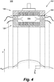
- Fig. 4 shows a schematic lateral cross-sectional side view of the process tunnel 102.
- the lower and upper tunnel bodies 120, 140 are in a closed configuration, but the joins 106 are not fluidtight.
- process gases injected into the tunnel space 104 flow sideways, and exit the tunnel space 104 through both the gas exhaust channels 130 in or directly adjacent the lateral tunnel walls 128 (solid arrows) and the leaking joins 160 (dotted arrows).
- Fig. 4 show a pressure diagram including two primary pressure curves.
- the solid curve represents a reference pressure distribution for the non-depicted situation in which the joins 160 are fluidtight; the solid curve thus indicates the pressure inside the process tunnel space 104 and through the gas exhaust channels 130.
- the dotted curve represents the pressure distribution for the depicted situation with leaking joins 106, and indicates the pressure inside the process tunnel space 104 and through the leaking joins 160.
- Two secondary, short dot-dashed pressure curves interconnecting the dotted and solid curves indicate the pressure distribution through the gas exhaust channels 130 for the depicted situation with leaking joins 160.
- P env indicates the pressure level of the environmental pressure.
- the solid pressure curve indicates that the gas pressure at the lateral center of the process tunnel space 104 is highest, and drops towards the gas exhaust conduits 110. Within the gas exhaust conduits 110, the pressure may fall off further until it eventually reaches environmental pressure P env , typically at the end of the gas exhaust conduit.
- process gas may escape from the process tunnel space 104.
- the leaking joins may cause a drop in the overall pressure distribution, as indicated by the dotted pressure curve. Note that the drop appears rather neat because the dotted pressure curve relates to the depicted situation with two mirror symmetrically leaking joins 160. In case the two joins 160 would leak in a different, non-symmetrical manner, the dotted curve would no longer be symmetrical around its center, but for instance appear subsided to the side of the largest leak.
- the deviation of the dotted pressure curve from the solid pressure curve may pose problems for the transport of contactlessly advanced, double-floatingly supported substrates 180.
- a floatingly supported substrate 180 would be accelerated upon entering this longitudinal portion, and decelerated upon leaving it.
- the joins 160 leaks too much, the substrate 180 may even come to a complete stop.
- the pressure adjacent one of the lateral tunnel walls 128 would be greater than that adjacent the opposite lateral tunnel wall 128. Consequently, a substrate 180 passing the leaking join(s) 160 would be destabilized and forced sideways, towards and possibly into contact with the lateral wall 128 adjacent the region of smallest pressure.
- the present disclosure suggests a different approach to solve the problem of uncontrolled leakage of gases into/from the process tunnel space 104 caused by the presence of the leaking joins 106.
- the joins 160 may be arranged such that they do not intersect the gas exhaust channels 130 provided in the lateral tunnel walls 128 or in at least one of the upper and the lower tunnel wall directly adjacent the lateral tunnel walls 128.
- a fluidtight connection between the gas exhaust channels 130 and the gas exhaust conduit(s) 110 is facilitated.
- isolating the gas exhaust channels 130 from the joins 160 enables the pressure drops across the joins 160 to be controlled independently from the pressure drops across the gas exhaust channels.
- pressure regulation means configured to equalize gas pressures on opposite sides of a join 160, such that a pressure drop ⁇ P join across the join obeys ⁇ P join ⁇ 0.
- the pressure drop across the join ⁇ P join is the difference between a gas pressure on an inside of the join 160, i.e. a gas pressure inside the process tunnel space 104, and a gas pressure on an outside of the join 160, i.e. a gas pressure outside of the process tunnel space 104, e.g. an environmental gas pressure P env .
- the pressure drop across the join 160 is successfully reduced to zero or at least approximately zero (i.e. ' ⁇ 0 ', which may be quantified to mean ' ⁇ 10 Pascals')
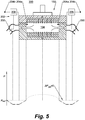
- a first elaboration may be illustrated with reference to Fig. 5 .
- the pressure drop ⁇ P join across a longitudinal, non-fluidtight part of the join 160 may be controlled by exercising control over a pressure on an inside of said part of the join, and more specifically by controlling a pressure inside a gas exhaust channel 130 adjacent said part of the join.
- the pressure regulation means may include a gas pump 200.
- the term 'gas pump' as used here may be construed broadly to include relatively economical devices such as extractor fans, ventilators and the like.
- the gas pump 200 may be associated with a gas exhaust channel 130 that is arranged longitudinally adjacent or near - e.g. within several centimeters, for instance within 100 mm and preferably 50 mm, of - the non-fluidtight part of the join 160.
- the gas pump 200 may, for instance, be arranged inside the gas exhaust conduit 110 that connects to the gas exhaust channel, and be adapted to control a gas pressure inside the gas exhaust channel 130 with which it is associated, in particular the gas pressure at an upstream entrance thereof. Because of its association with the gas pump 200, the gas exhaust channel 130 in question may be referred to as a 'controlled gas exhaust channel'.
- the pressure regulation means may further include a pressure control system 202, which may be configured to control the pressure inside the controlled gas exhaust channel 130 by controlling the gas pump 200, so as to locally effect a condition ⁇ P join ⁇ 0 adjacent the controlled gas exhaust channel.
- the pressure control system 202 may typically include a differential pressure sensor 204a, 204b that is associated with the controlled gas exhaust channel 130 and configured to monitor a pressure difference between a first location inside the process tunnel space 104, normally located near to both the non-fluidtight part of the join 160 and the controlled gas exhaust channel 130, and a second location outside the process tunnel space 204 (i.e. in the environment of the process tunnel 102), and to generate a signal reflecting the pressure difference.
- the differential pressure sensor may thus include two spaced apart pressure sensors 204a and 204b, as schematically depicted in Fig. 5 .
- the pressure control system may also comprise a controller 206.
- the controller 206 may be operably connected to both the differential pressure sensor 204a, 204b and the gas pump 200, and be configured to control the gas pump in dependence of the signal received from the differential pressure sensor, so as to locally effect the condition ⁇ P join ⁇ 0 adjacent the controlled gas exhaust channel 130.
- FIG. 5 shows a dotted pressure curve that represents the pressure distribution for the depicted situation with non-fluidtight joins 160, and indicates the pressure inside the process tunnel space 104 and through the joins 160.
- the secondary dot-dashed pressure curves indicate the pressure distribution through the gas exhaust channels 130 and gas conduits 110..
- a second elaboration may be illustrated with reference to Fig. 6 .
- the pressure drop AP join across a longitudinal, non-fluidtight part of the join 160 may be controlled by exercising control over a pressure on an outside of the join 160.
- the pressure regulation means may comprise an auxiliary containment 210 that defines a buffer space 211 configured to contain a preferably inert, pressurized buffer gas such as nitrogen (N 2 ), which buffer space is in fluid communication with (an outside of) the part of the join 160 across which the pressure drop is to be controlled.
- the auxiliary containment may take the shape of an elongate box- or channel-like structure that extends outside of and along the lateral walls 128 of the process tunnel 102, as schematically shown in Fig. 6 .
- the auxiliary containment may include at least two wall parts, one of which is fixedly connected to the lower tunnel body 120, and one of which is fixedly connected to the upper tunnel body 140.
- the auxiliary containment may simply be connected to one of the tunnel bodies 120, 140.
- the buffer space 211 defined by the auxiliary containment 210 need not be completely fluidtight.
- the construction of the auxiliary containment 210 and/or its connections to the process tunnel 102 may include leaks, as long as the pump 212 used to pressurize the buffer gas in the buffer space 211 (see below) is capable of maintaining the buffer gas at a desired bulk pressure necessary to maintain the condition ⁇ P join ⁇ 0.
- the pressure regulation means may further include a gas pump 212.
- the term 'gas pump' as used here may be construed broadly to include devices (gas) compressors and the like.
- the gas pump 212 may, on the one hand, be operably connected to a source of a suitable, preferably inert buffer gas, and, on the other hand, to the secondary containment 210, so as to be able to pressurize the buffer space 211 with said buffer gas.
- the gas pump 212 may typically operate under the control of a pressure control system 214 that is configured to control a pressure of the buffer gas inside the buffer space 211 by controlling the gas pump 212, so as to effect and maintain the desired condition ⁇ P join ⁇ 0.
- the pressure control system may, for instance, include a differential pressure sensor 216a, 216b that is configured to monitor a pressure difference between a first location inside the process tunnel space 104 and a second location inside the buffer space 211, and to generate a signal reflecting the pressure difference.
- the pressure control system may also include a controller 218 that is operably connected to both the differential pressure sensor 216a, 216b and the gas pump 212, and configured to control the gas pump in dependence of the signal received from the differential pressure sensor, so as to an approximately zero pressure drop across the join 160.
- the diagram at the bottom of Fig. 6 shows a dotted pressure curve that represents the pressure distribution for the depicted situation with non-fluidtight joins 160, and indicates the pressure inside the process tunnel space 104 and through the joins 160.
- the secondary dot-dashed pressure curves indicate the pressure distribution through the gas exhaust channels 130 and gas conduits 110.
Landscapes
- Chemical & Material Sciences (AREA)
- Engineering & Computer Science (AREA)
- Mechanical Engineering (AREA)
- Metallurgy (AREA)
- Materials Engineering (AREA)
- Chemical Kinetics & Catalysis (AREA)
- General Chemical & Material Sciences (AREA)
- Organic Chemistry (AREA)
- Physics & Mathematics (AREA)
- Fluid Mechanics (AREA)
- Chemical Vapour Deposition (AREA)
- Container, Conveyance, Adherence, Positioning, Of Wafer (AREA)
- Delivering By Means Of Belts And Rollers (AREA)
- Formation Of Insulating Films (AREA)
Description
- The present invention relates to a high-throughput substrate processing apparatus for processing double-floatingly supported substrates during transport through a process tunnel.
- International patent application publication
WO 2011/062490 in the name of Levitech B.V. discloses a substrate processing apparatus including a process tunnel through which semiconductor substrates may be contactlessly advanced in rapid succession while being subjected to a variety of treatments such as, for example, spatial atomic layer deposition (ALD) and annealing. A problem addressed in WO'490 is that the substrates, which are floatingly supported between an upper and lower gas bearing, may become destabilized by gas flows necessary to maintain the gas bearings. Consequently, the substrates may stray from their predetermined trajectory towards the edges of the gas bearings and/or undergo angular displacements, as a result of which they may collide with and/or get stuck between the walls bounding the process tunnel. Although the lateral stabilization mechanism proposed by WO'490 works satisfactorily in significantly reducing the occurrence rate of such events, practice has taught that substrate-wall contacts may not be prevented entirely. - In the event that a substrate-wall contact involves fracture of the substrate and/or congestion of the process tunnel, quick and convenient access to the tunnel space is desired in order to enable operators to remedy the situation and to effect prompt resumption of the production process. The same applies, of course, in case a substrate fractures or gets stuck for other reasons. In practice, for instance, a substrate may already be slightly damaged upon insertion into the process tunnel. If such a substrate is then rapidly heated as part of a (pre-)anneal treatment, the thermal expansion of the cracked substrate may cause it to break into pieces.
- It is therefore an object of the present invention to provide for an adapted version of the substrate processing apparatus discussed in WO'490, which adapted version enables an operator to quickly access the process tunnel space in order to remedy any problems therein, and to effect a prompt continuation of operation, preferably within about 10-30 minutes after detection of the problem.
- To this end, a first aspect of the present invention is directed to a substrate processing apparatus. The apparatus may comprise a process tunnel including a lower tunnel wall, an upper tunnel wall, and two lateral tunnel walls. The tunnel walls may be configured to bound a process tunnel space that extends in a longitudinal transport direction and that is suitable for accommodating at least one substantially planar substrate oriented parallel to the upper and lower tunnel walls. The apparatus may also comprise a plurality of gas injection channels provided in both the lower and the upper tunnel wall. Gas injection channels in the lower tunnel wall may be configured to provide for a lower gas bearing, while the gas injection channels in the upper tunnel wall may be configured to provide for an upper gas bearing. The gas bearings may be configured to floatingly support and accommodate the substrate there between. The substrate processing apparatus may also comprise a plurality of gas exhaust channels provided in both the lateral tunnel walls. Alternatively the exhaust channels may be provided in at least one of the upper and the lower tunnel wall directly adjacent both lateral walls. In this respect "directly adjacent" means within a distance of less than 5 mm and more preferably less than 2 mm from the associated lateral wall. Preferably, "directly adjacent" also means that a said exhaust channel in the upper or the lower tunnel wall is positioned so close to one of said lateral walls that a circumferential edge of said gas exhaust channel in the upper or lower tunnel wall touches that associated lateral wall. The gas exhaust channels in or directly adjacent each lateral tunnel wall may be spaced apart in the transport direction. The process tunnel may be divided in a lower tunnel body comprising the lower tunnel wall and an upper tunnel body comprising the upper tunnel wall. The tunnel bodies may be separably joinable to each other along at least one longitudinally extending join, such that they are mutually movable between a closed configuration in which the tunnel walls bound the process tunnel space and an open configuration that enables lateral maintenance access to an interior of the process tunnel.
- During operation, the tunnel bodies may be in the closed configuration. In case a substrate then breaks or gets stuck inside the process tunnel, the transport of further substrates through the tunnel may be paused, and the tunnel bodies may be separated or disjoined and be brought into their open configuration in order to allow an operator to access the interior of the process tunnel to remove the broken or stuck substrate.
- The respective tunnel bodies may preferably extend over the entire length of the process tunnel (typically at least several meters, e.g. 5-15 meters), and be unitary so as to be movable relative to each other as respective wholes. Accordingly, opening and closing the process tunnel may mean opening and closing the process tunnel over its entire length. In such a configuration, an operator seeking to remedy a problem within the tunnel space does not need to localize the problem before accessing the tunnel, which provides an improvement over an embodiment in which, for instance, the upper tunnel body is comprised of respective, longitudinally arranged upper tunnel sub-bodies that are movable relative to a unitary lower tunnel body. In the case of a congestion, an operator of this latter embodiment would have to decide which of the upper tunnel sub-bodies he should (re)move to get access to the interior of the process tunnel. The congestion, however, may be difficult to localize, and may not be confined to a single location in the process tunnel. Furthermore, in particular when heated gases are used for the gas bearings, (re)moving one or more upper tunnel sub-bodies may cause them to cool at a different rate than the remaining upper tunnel sub-bodies (which, conversely, may be given room to expand), as a result of which the (re)moved upper tunnel sub-bodies may not seamlessly fit back into place before the entire process tunnel has cooled down. Since such cooling of the process tunnel may take hours, and corresponds to downtime of the apparatus, a configuration with separate upper or lower tunnel sub-bodies may best be avoided.
- The upper and lower tunnel bodies may be movable relative to each other in various ways. In one embodiment, for instance, the upper and lower tunnel bodies may be movably connected along a longitudinally extending axis around which they may hinge or pivot relative to each other in a clamshell-like fashion. In another, preferred embodiment the upper and lower tunnel bodies may be completely separable from one another. The apparatus comprises a clamp (device) or press, e.g. a hydraulic clamp/press, configured to force the upper and lower tunnel bodies together to effect the closed configuration. In an embodiment, the clamp or press may additionally be configured to separate the upper and lower tunnel bodies in order to effect the open configuration. Completely separable upper and lower tunnel bodies may generally be preferred as they enable a tighter-closed configuration: hinges and the like require mechanical play that may be at variance with the desire to effect tight joins between the upper and lower tunnel bodies. However, in an embodiment, the substrate processing apparatus may include a hinge that is connected with both the upper and the lower tunnel body and that is configured to hinge the upper tunnel body relative to the lower tunnel body in order to effect the open configuration and to bring the upper and lower tunnel bodies together along the a least longitudinally extending join. When the bodies are brought together by means of the hinge, again at least one clamp or a press may force the upper and the lower tunnel bodies together along the at least one longitudinally extending join to effect the closed configuration in which a tight join between the upper and the lower tunnel bodies is effected.
- In a typical embodiment fitted with a clamp or press, the upper and lower tunnel walls may be substantially flat, while the press may be configured to move the upper and lower tunnel bodies with the upper and lower tunnel walls in a parallel relationship.
- In an embodiment of the apparatus, the lower tunnel body may comprise the two lateral tunnel walls, such that its lower tunnel wall and lateral tunnel walls together define a longitudinally extending open channel having a generally U-shaped transverse cross-sectional profile. Having the lower tunnel body instead of the upper tunnel body include the lateral tunnel walls prevents substrates present in the process tunnel from inadvertently sliding or floating out under the action of gravity when the tunnel is opened; the lateral walls will contain the substrates, and any debris, thus facilitating their removal.
- In another embodiment, at least one and preferably both of the lateral tunnel walls may define a respective flat upward facing join surface, while the upper tunnel wall may be substantially flat and define one or more respective flat downward facing join surface(s) that is/are configured to abut the respective flat upward facing join surface(s) in the closed configuration, so as to define the at least one longitudinally extending join.
- The contactless transport of double-floatingly supported substrates through the process tunnel is a process to which an accurately controlled pressure distribution inside the process tunnel is of paramount importance. This is true whether the transport is driven by gravity, as discussed in for instance
WO 2009/142,487 (Granneman et al. ) in the name of ASM International N.V., or through a longitudinal pressure distribution, as described inWO 2012/005,577 (Granneman et al. ) in the name of Levitech B.V. Uncontrolled pressure deviations as small as a few Pascals may destabilize or even halt substrates whizzing through the process tunnel. - Unfortunately, an inherent disadvantage of the process tunnel being divided into relatively movable upper and lower tunnel bodies is that at least one join, and typically two joins, exist between these tunnel bodies. These joins may not be completely fluid tight, and thus represent leaks through which gas may be exchanged between the process tunnel space and the environment. In particular in case the gases used inside the process tunnel space are toxic or mutually reactive, they may contaminate a clean room environment and/or affect the health of employees working therein; conversely, the exchange of gases might also contaminate the process tunnel space itself. To avoid chemical contamination of the process tunnel space through the inflow of environmental air, the gas bearings in the process tunnel space may typically be maintained at a slightly super-atmospheric pressure. This solution, however, neither prevents the uncontrolled leakage of process gases from the process tunnel space, nor the associated uncontrolled local pressure variations - typically pressure drops - adjacent the leak.
- In line with general practice, one may attempt to avoid uncontrolled leakage and local pressure variations by making the joins as fluid tight as possible, for instance by applying an elongate O-ring along the joins between the tunnel bodies, and by additionally bolting the opposite tunnel bodies together along the join, so as to clamp the O-rings between the tunnel bodies to seal the join. In the present context, however, O-rings, are generally undesirable. Most O-rings cannot be used at temperatures above 150°C, and/or in chemically aggressive environments involving ALD-precursors such as trimethylaluminum (TMA). O-rings that would be suitable on technical grounds are very costly. Accordingly, the use of O-rings in the present context is rather uneconomical since the O-ring material would have to be provided along one or more joins extending the length of the entire process tunnel (typically about 5-10 meters). Moreover, the use of bolts to bolt the upper and lower tunnel bodies together is impractical as unbolting the upper and lower tunnel bodies along the entire length of the track would be very time-consuming (not only because of the number of bolts, but also because unbolting may require the process tunnel to have cooled down), and therefore hamper a fast remedy to a problem inside the process tunnel space.
- As attempting to conventionally seal the joins is both uneconomical and impractical, the present disclosure suggests a different approach to solve the problem of uncontrolled leakage of gases into/from the process tunnel space caused by the presence of the joins. To enable this approach, the joins may be arranged such that they do not intersect the gas exhaust channels provided in or directly adjacent the lateral tunnel walls.
- An external or downstream end of a gas exhaust channel in a lateral tunnel wall may typically be connected to a gas exhaust conduit to discharge process gas to a desired location. By ensuring that the gas exhaust channel is not intersected by a join, a fluid tight connection between the gas exhaust channel and the gas exhaust conduit is facilitated (this is because an upstream end of the gas exhaust conduit may now simply be permanently connected to the lateral wall, such that it is in fluid communication with the gas exhaust channel, without having to consider the relative movability of the tunnel bodies). Moreover, isolating the gas exhaust channel from the join enables a pressure drop across the join to be controlled independently from a pressure drop across the gas exhaust channel.
- This latter aspect is key to two elaborations of the presently disclosed apparatus, in which pressure regulation means are provided, configured to equalize pressures on opposite sides of the join, such that a pressure drop ΔPjoin across the join obeys ΔPjoin ≈ 0. When the pressure drop across the join is successfully reduced to zero or at least approximately zero (i.e. '≈ 0', which may be quantified to mean '< 10 Pascals', i.e. 'less than 10 Pascals'), there is substantially no pressure difference across the join to drive a gas flow. Consequently, there is effectively no leak either.
- In a first of said elaborations, the pressure drop across a longitudinal, non-fluidtight (i.e. possibly leaking) part of the join may be controlled by exercising control over a pressure on an inside of said part of the join. More specifically, by controlling a gas pressure inside a gas exhaust channel adjacent said part of the join, a gas pressure at an upstream entrance of the gas exhaust channel, and thus at an inside of the join, may be equalized with an (environmental) pressure on an outside of the join.
- In a second of said elaborations, the pressure drop across a longitudinal, non-fluidtight part of the join may be controlled by exercising control over a pressure on an outside of said part of the join. To this end, the pressure regulation means may, for instance, comprise an auxiliary containment that defines a buffer space configured to contain a preferably inert, pressurized buffer gas such as nitrogen, which buffer space is in fluid communication with (an outside of) the part of the
join 160 across which the pressure drop is to be controlled. A gas pressure of the buffer gas in the buffer space may then be equalized with a (process gas) pressure on an inside of the join, inside the process tunnel space, so as to effect a zero pressure drop across the non-fluidtight part of the join. - These and other features and advantages of the invention will be more fully understood from the following detailed description of certain embodiments of the invention, taken together with the accompanying drawings, which are meant to illustrate and not to limit the invention.
-
-
Fig. 1 schematically illustrates a cross-sectional side view of a longitudinal process tunnel section of an exemplary embodiment of a substrate processing apparatus according to the present disclosure; -
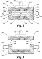
Fig. 2 schematically illustrates a lateral cross-sectional side view of the process tunnel section shown inFig. 1 , with the upper and lower tunnel bodies in a closed configuration (no leaks); -
Fig. 3 schematically illustrates a lateral cross-sectional side view of the process tunnel section shown inFig. 1 , with the upper and lower tunnel bodies in an open configuration; -
Fig. 4 schematically illustrates a lateral cross-sectional side view of the process tunnel section shown inFig. 1 , wherein the upper and lower tunnel bodies are in a closed, yet leaking configuration; -
Fig. 5 schematically illustrates a lateral cross-sectional side view of a first elaboration of the substrate processing apparatus shown inFigs. 1-3 , including pressure regulation means configured to equalize pressures on opposite sides of the joins; and -
Fig. 6 schematically illustrates a lateral cross-sectional side view of a second elaboration of the substrate processing apparatus shown inFigs. 1-3 , including pressure regulation means configured to equalize pressures on opposite sides of the joins. - Below, a basic exemplary embodiment of a substrate processing apparatus according to the present disclosure is described with reference to
Figs. 1-3 . The exemplary embodiment is set up as a spatial atomic layer deposition (ALD) apparatus. It is understood, however, that the scope of application of the apparatus is not limited to the field of atomic layer deposition. The apparatus may alternatively be applied for the purpose of performing other substrate processing treatments, such as annealing. - Referring now to
Figs. 1-3 . The disclosedapparatus 100 may include a typically linear orstraight process tunnel 102 through which asubstrate 180, e.g. a silicon wafer, preferably as part of a train of substrates, may be conveyed in a uni-directional or bi-directional manner. That is, thesubstrate 180 may be inserted into theprocess tunnel 102 at an entrance thereof, and be uni-directionally conveyed to an exit. Alternatively, theprocess tunnel 102 may have a dead end and thesubstrate 180 may undergo a bi-directional motion from an entrance of the process tunnel, towards the dead end, and back to the entrance. Such an alternative bi-directional system may be preferred if an apparatus with a relatively small footprint is desired. - The
process tunnel 102 may include both an elongate (i.e. longitudinally extending)lower tunnel body 120 and an elongateupper tunnel body 140. In a preferred embodiment, such as that shown inFigs.1-3 , thelower tunnel body 120 may include alower tunnel wall 122 and twolateral tunnel walls 128 that protrude upwardly from thelower tunnel wall 122 on respective, opposite lateral sides thereof; theupper tunnel body 140 may then include an upper tunnel wall 142 (seeFig. 2 ). In alternative embodiments, one or both of thelateral tunnel walls 128 may form part of theupper tunnel body 140 instead, and protrude downwardly from the upper tunnel wall. An advantage of having thelower tunnel body 120 include bothlateral tunnel walls 128 is that it has a generally U-shaped transverse cross-sectional tunnel wall profile that, when the lower andupper tunnel bodies Fig. 3 , to be described below), defines a longitudinally extending open channel which is still capable of containing substrates and substrate debris: the U-shaped wall profile of the lower tunnel body prevents any substrates and substrate debris from inadvertently sliding out under the action of gravity. - The lower and
upper tunnel bodies Fig. 2 ). The at least onejoin 160 may enable the lower andupper tunnel bodies Figs. 1-2 ), thetunnel walls process tunnel space 104. In the open configuration (seeFig. 3 ), in which thetunnel bodies join 160, the tunnel bodies may define at least one, and typically two, elongate access opening(s) or gap(s) 106 between them that enable(s) maintenance access to the interior of the process tunnel (i.e. to the space that, in the closed configuration, forms the process tunnel space 104) from a lateral side of theprocess tunnel 102. - The relative movability of the
tunnel bodies lower tunnel bodies Figs. 1-3 , the upper andlower tunnel bodies apparatus 100 comprises one or more clamp devices or presses 190, e.g. hydraulic clamps/presses, configured to alternatively force the lower andupper tunnel bodies lower tunnel body 120 is fixedly connected to the world, while theupper tunnel body 140 is movably arranged by means of a series of longitudinally spaced apart presses 190 (Fig. 1 ), such that it can alternatively be pressed down on the lower tunnel body (Fig. 2 ) or be lifted therefrom (Fig. 3 ). Completely separable upper andlower tunnel bodies lower tunnel bodies - The at least one
join 160 may be defined by two opposing join surfaces 132, 148 provided on the lower andupper tunnel bodies lower tunnel body 120 includes at least onelateral tunnel wall 128, thistunnel wall 128 may define a preferably flat upward facingjoin surface 132, while theupper tunnel body 140 may define a preferably flat downward facingjoin surface 148. The downward facingjoin surface 148 may be co-planar or flush with an inner surface of theupper wall 122, and be configured to abut the flat upward facingjoin surface 132 of thelateral wall 128 in the closed configuration of thetunnel bodies join surface 148 may thus be formed as an elongate, lateral extension of the inner/lower surface of theupper tunnel wall 122. An advantage of having anupper tunnel body 140 with an entirely flat lower surface is that the successful (sealing) mating of the join surfaces 132, 148 is relatively insensitive to the precise lateral and/or longitudinal alignment of the lower andupper tunnel bodies - In the closed configuration, the lower and
upper tunnel walls 122, 142 may be oriented horizontally or at an angle relative to the horizontal (e.g. to enable gravity driven substrate transport), be mutually parallel, and be spaced apart slightly, e.g. 0.5-1 mm, such that a substantially flat orplanar substrate 180, having a thickness of for example 0.1-1 mm and oriented parallel to the upper andlower tunnel walls 122, 142, may be accommodated therebetween without touching them. Also in the closed configuration, thelateral tunnel walls 128, which may be oriented substantially vertically and be mutually parallel, may interconnect the lower andupper tunnel walls 122, 142 at their lateral sides. Thelateral walls 128 may be spaced apart by a distance somewhat larger than a width of asubstrate 180 to be processed, e.g. its width plus 0.5-3 mm. Accordingly, thetunnel walls process tunnel space 104 having a relatively small volume per unit of tunnel length, and capable of snugly accommodating one ormore substrates 180 that are successively arranged in the longitudinal direction T of thetunnel 102. - Both the
lower tunnel wall 122 and the upper tunnel wall 142 may be provided with a plurality ofgas injection channels gas injection channels wall 122, 142 may be arranged as desired as long as at least a number of them is dispersed across the length of theprocess tunnel 102.Gas injection channels respective tunnel wall - The
gas injection channels same tunnel wall 122, 142 and at a same longitudinal position thereof are connected to a gas source of a same gas or gas mixture. For ALD-purposes, thegas injection channels lower wall 122 and theupper wall 132 may, viewed in the transport direction T, be successively connected to a first precursor gas source, a purge gas source, a second precursor gas source and a purge gas source, so as to create a functional ALD-segment 108 (seeFig. 1 ) that - in use - comprises successive tunnel-wide gas zones including a first precursor gas, a purge gas, a second precursor gas and a purge gas, respectively. It is understood that one such an ALD-segment 108 corresponds to a single ALD-cycle. Accordingly, multiple ALD-segments 108 may be arranged in succession in the transport direction T to enable the deposition of a film of a desired thickness. Different ALD-segments 108 within aprocess tunnel 102 may, but need not, comprise a same combination of precursors. Differently composed ALD-segments 108 may for example be employed to enable the deposition of mixed films. - Whether opposing
gas injection channels opposite tunnel walls 122, 142, are connected to gas sources of a same gas composition may depend on the desired configuration of theapparatus 100. In case double-sided deposition is desired, i.e. ALD treatment of both alower surface 180a and anupper surface 180b of asubstrate 180 travelling through theprocess tunnel 102, opposinggas injection channels lower surface 180a andupper surface 180b of asubstrate 180,gas injection channels tunnel wall 122, 142 facing the substrate surface to be treated may be alternatingly connected to a reactive and an inert gas source, while gas injection channels in the other tunnel wall may all be connected to an inert gas source. - In the exemplary embodiment of
Figs. 1-3 , thegas injection channels 144 in the upper wall 142 are successively connected to a trimethylaluminum (Al(CH3)3, TMA) source, a nitrogen (N2) source, a water (H2O) source, and a nitrogen source, so as to form a series of identical ALD-segments 108 suitable for performing aluminum oxide (Al2O3) atomic layer deposition cycles. Thegas injection channels 124 in thelower tunnel wall 122, in contrast, are all connected to a nitrogen source. Accordingly, theexemplary apparatus 100 is set up to maintain lowernon-depositing gas bearing 126 and an upperdepositing gas bearing 146, together configured to perform single-sided deposition on atop surface 180b of a passing, floatingly supportedsubstrate 180. - Each of the
lateral walls 128 of theprocess tunnel 102 may, along its entire length or a portion thereof, be provided with a plurality ofgas exhaust channels 130. Alternatively, the gas exhaust channels may be provided in at least one of the upper and the lower tunnel wall directly adjacent both lateral walls. In this respect "directly adjacent" means within a distance of less than 2 mm from the respective lateral wall. Thegas exhaust channels 110 may be spaced apart - preferably equidistantly - in the longitudinal direction of theprocess tunnel 102. The distance between two neighboring or successivegas exhaust channels 130 in or directly adjacent a samelateral wall 128 may be related to a length of thesubstrates 180 to be processed; in this text, the 'length' of a typicallyrectangular substrate 180 may be construed as the dimension of the substrate extending in the longitudinal direction T of theprocess tunnel 102. A lateral wall portion the length of asubstrate 180 may preferably comprise between approximately 5 and 20, and more preferably between 8 and 15,exhaust channels 130. A center-to-center distance between two successivegas exhaust channels 130 may be in the range of approximately 10-30 mm. For reasons of substrate stabilization, the configuration ofgas exhaust channels 130 in or directly adjacent the twolateral walls 128 may preferably be identical or mirror symmetric, such that eachgas exhaust channel 130 in or directly adjacent onelateral wall 128 faces agas exhaust channel 130 in or directly adjacent the other, oppositelateral wall 128. - The
gas exhaust channels 130 may be connected to and discharge intogas exhaust conduits 110, which may be provided on the outside of theprocess tunnel 102. In case theapparatus 100 is set up to perform ALD, the exhaust gases may contain quantities of unreacted precursors. Accordingly, it may be undesirable to connectgas exhaust channels 130 associated with mutually different reactive gas zones to a same gas exhaust conduit 110 (which may unintentionally lead to chemical vapor deposition). Differentgas exhaust conduits 110 may thus be provided for different precursors. - The general operation of the
apparatus 100 may be described as follows. - In use, the lower and
upper tunnel bodies gas injection channels upper tunnel walls 122, 142 may inject gas into theprocess tunnel space 104. To prevent contaminating gas flows from a typically atmosphericclean room environment 300 of theprocess tunnel 102 into theprocess tunnel space 104, e.g. at the entrance and the exit of theprocess tunnel 102, theprocess tunnel space 104 may preferably be kept at a slightly super-atmospheric pressure. Accordingly, gas injection may take place at an overpressure (relative to atmospheric pressure) on the order of several millibars. In case a somewhat smaller overpressure is maintained in thegas exhaust conduits 110, gas injected into thetunnel space 104 will naturally flow sideways, transverse to the longitudinal direction T of the process tunnel, and towards and through thegas exhaust channels 130 in or directly adjacent thelateral tunnel walls 108 that connect to theexhaust conduits 110. - In case a
substrate 180 is present between the upper andlower tunnel walls 122, 142, the gas(es) injected into thetunnel space 104 by thegas injection channels 144 in the upper tunnel wall 142 may flow sideways between the upper tunnel wall 142 and atop surface 180b of thesubstrate 180. These lateral gas flows across atop surface 180b of thesubstrate 180 effectively provide for anupper gas bearing 146. Likewise, the gas(es) injected into thetunnel space 104 by thegas injection channels 124 in thelower tunnel wall 122 will flow sideways between the lower tunnel wall and alower surface 180a of thesubstrate 180. These lateral gas flows across thelower surface 180a of thesubstrate 180 effectively provide for alower gas bearing 126. The lower andupper gas bearings substrate 180. - As the
substrate 180 moves through theprocess tunnel 102, itssurfaces gas bearings apparatus 100 is setup for ALD, for instance like the apparatus depicted inFigs.1-3 , itsupper surface 180b may be strip-wise subjected to the gases present in each of the successively arranged gas zones of theupper gas bearing 146. Provided that the arrangements of the zones and the respective gases are chosen properly, traversal of one ALD-segment 108 may be equivalent to subjecting thesubstrate 140 to one atomic layer deposition cycle. Since thetunnel 102 may comprise as many ALD-segments 108 as desired, a film of arbitrary thickness may be grown on thesubstrate 140 during its crossing of the tunnel. The linear nature of theprocess tunnel 102 further enables a continuous stream ofsubstrates 140 to be processed, thus delivering an atomiclayer deposition apparatus 100 with an appreciable throughput capacity. - Unfortunately, the linear nature of the
process tunnel 102 also entails that the processing ofsubstrates 180 is halted in case asubstrate 180 gets stuck or breaks inside the process tunnel. In such an event, thetunnel bodies Fig. 3 ) in order to allow an operator to access the interior of theprocess tunnel 120 via theaccess openings 106, and to remove the broken orstuck substrate 180. Once the problem has been remedied, thetunnel bodies - Although the joins 160 between the lower and
upper tunnel bodies process tunnel space 104 and aclean room environment 300 accommodating theprocess tunnel 102. In case theprocess tunnel space 104 is maintained at an overpressure relative to the environment 300 (see above), such leaks may cause contamination of the environment with process gases. In addition, the uncontrolled leakage of process gases from theprocess tunnel space 104 may cause uncontrolled local pressure variations within theprocess tunnel space 104, which may seriously hamper the transport ofsubstrates 180 therethrough. - The effect of leaking joins 106 on the pressure distribution inside the
process tunnel 102 may be illustrated with reference toFig. 4 . At the top,Fig. 4 shows a schematic lateral cross-sectional side view of theprocess tunnel 102. The lower andupper tunnel bodies tunnel space 104 flow sideways, and exit thetunnel space 104 through both thegas exhaust channels 130 in or directly adjacent the lateral tunnel walls 128 (solid arrows) and the leaking joins 160 (dotted arrows). At the bottom,Fig. 4 show a pressure diagram including two primary pressure curves. The solid curve represents a reference pressure distribution for the non-depicted situation in which the joins 160 are fluidtight; the solid curve thus indicates the pressure inside theprocess tunnel space 104 and through thegas exhaust channels 130. The dotted curve represents the pressure distribution for the depicted situation with leaking joins 106, and indicates the pressure inside theprocess tunnel space 104 and through the leaking joins 160. Two secondary, short dot-dashed pressure curves interconnecting the dotted and solid curves indicate the pressure distribution through thegas exhaust channels 130 for the depicted situation with leaking joins 160. On the vertical pressure (P) axis of the diagram, Penv indicates the pressure level of the environmental pressure. - The solid pressure curve indicates that the gas pressure at the lateral center of the
process tunnel space 104 is highest, and drops towards thegas exhaust conduits 110. Within thegas exhaust conduits 110, the pressure may fall off further until it eventually reaches environmental pressure Penv , typically at the end of the gas exhaust conduit. In the case of leaking joins 160, process gas may escape from theprocess tunnel space 104. Compared to the non-leaking case, the leaking joins may cause a drop in the overall pressure distribution, as indicated by the dotted pressure curve. Note that the drop appears rather neat because the dotted pressure curve relates to the depicted situation with two mirror symmetrically leaking joins 160. In case the two joins 160 would leak in a different, non-symmetrical manner, the dotted curve would no longer be symmetrical around its center, but for instance appear subsided to the side of the largest leak. - As mentioned, the deviation of the dotted pressure curve from the solid pressure curve may pose problems for the transport of contactlessly advanced, double-floatingly supported
substrates 180. For instance, in case the joins 160 are leaking over a certain longitudinal portion of the process tunnel, a floatingly supportedsubstrate 180 would be accelerated upon entering this longitudinal portion, and decelerated upon leaving it. In case the joins 160 leaks too much, thesubstrate 180 may even come to a complete stop. Similarly, in case only one of the joins 160 is leaking, or the opposite joins 160 are leaking non-(mirror) symmetrically, the pressure adjacent one of thelateral tunnel walls 128 would be greater than that adjacent the oppositelateral tunnel wall 128. Consequently, asubstrate 180 passing the leaking join(s) 160 would be destabilized and forced sideways, towards and possibly into contact with thelateral wall 128 adjacent the region of smallest pressure. - Since attempts to conventionally seal the joins 160 by means of sealing materials like O-rings are either impractical or uneconomical, the present disclosure suggests a different approach to solve the problem of uncontrolled leakage of gases into/from the
process tunnel space 104 caused by the presence of the leaking joins 106. To enable this approach, the joins 160 may be arranged such that they do not intersect thegas exhaust channels 130 provided in thelateral tunnel walls 128 or in at least one of the upper and the lower tunnel wall directly adjacent thelateral tunnel walls 128. By ensuring that thegas exhaust channels 130 are not intersected by joins 160, a fluidtight connection between thegas exhaust channels 130 and the gas exhaust conduit(s) 110 is facilitated. Moreover, isolating thegas exhaust channels 130 from the joins 160 enables the pressure drops across the joins 160 to be controlled independently from the pressure drops across the gas exhaust channels. - This latter aspect is key to two elaborations of the presently disclosed
apparatus 100 in which pressure regulation means are provided, configured to equalize gas pressures on opposite sides of ajoin 160, such that a pressure drop ΔPjoin across the join obeys ΔPjoin ≈ 0. Is is understood that the pressure drop across the join ΔPjoin is the difference between a gas pressure on an inside of thejoin 160, i.e. a gas pressure inside theprocess tunnel space 104, and a gas pressure on an outside of thejoin 160, i.e. a gas pressure outside of theprocess tunnel space 104, e.g. an environmental gas pressure Penv . When the pressure drop across thejoin 160 is successfully reduced to zero or at least approximately zero (i.e. '≈ 0', which may be quantified to mean '< 10 Pascals'), there is substantially no pressure difference across thejoin 160 to drive a gas flow. Consequently, there is effectively no leak either. - A first elaboration may be illustrated with reference to
Fig. 5 . In this elaboration, the pressure drop ΔPjoin across a longitudinal, non-fluidtight part of thejoin 160 may be controlled by exercising control over a pressure on an inside of said part of the join, and more specifically by controlling a pressure inside agas exhaust channel 130 adjacent said part of the join. - To this end, the pressure regulation means may include a
gas pump 200. The term 'gas pump' as used here may be construed broadly to include relatively economical devices such as extractor fans, ventilators and the like. Thegas pump 200 may be associated with agas exhaust channel 130 that is arranged longitudinally adjacent or near - e.g. within several centimeters, for instance within 100 mm and preferably 50 mm, of - the non-fluidtight part of thejoin 160. Thegas pump 200 may, for instance, be arranged inside thegas exhaust conduit 110 that connects to the gas exhaust channel, and be adapted to control a gas pressure inside thegas exhaust channel 130 with which it is associated, in particular the gas pressure at an upstream entrance thereof. Because of its association with thegas pump 200, thegas exhaust channel 130 in question may be referred to as a 'controlled gas exhaust channel'. - The pressure regulation means may further include a
pressure control system 202, which may be configured to control the pressure inside the controlledgas exhaust channel 130 by controlling thegas pump 200, so as to locally effect a condition ΔPjoin ≈ 0 adjacent the controlled gas exhaust channel. Thepressure control system 202 may typically include adifferential pressure sensor gas exhaust channel 130 and configured to monitor a pressure difference between a first location inside theprocess tunnel space 104, normally located near to both the non-fluidtight part of thejoin 160 and the controlledgas exhaust channel 130, and a second location outside the process tunnel space 204 (i.e. in the environment of the process tunnel 102), and to generate a signal reflecting the pressure difference. It is understood that the differential pressure sensor may thus include two spaced apartpressure sensors Fig. 5 . The pressure control system may also comprise acontroller 206. Thecontroller 206 may be operably connected to both thedifferential pressure sensor gas pump 200, and be configured to control the gas pump in dependence of the signal received from the differential pressure sensor, so as to locally effect the condition ΔPjoin ≈ 0 adjacent the controlledgas exhaust channel 130. - The diagram at the bottom of
Fig. 5 shows a dotted pressure curve that represents the pressure distribution for the depicted situation with non-fluidtight joins 160, and indicates the pressure inside theprocess tunnel space 104 and through the joins 160. The secondary dot-dashed pressure curves indicate the pressure distribution through thegas exhaust channels 130 andgas conduits 110.. - A second elaboration may be illustrated with reference to
Fig. 6 . In this elaboration, the pressure drop APjoin across a longitudinal, non-fluidtight part of thejoin 160 may be controlled by exercising control over a pressure on an outside of thejoin 160. - To this end, the pressure regulation means may comprise an
auxiliary containment 210 that defines abuffer space 211 configured to contain a preferably inert, pressurized buffer gas such as nitrogen (N2), which buffer space is in fluid communication with (an outside of) the part of thejoin 160 across which the pressure drop is to be controlled. In some embodiments, the auxiliary containment may take the shape of an elongate box- or channel-like structure that extends outside of and along thelateral walls 128 of theprocess tunnel 102, as schematically shown inFig. 6 . In one embodiment, the auxiliary containment may include at least two wall parts, one of which is fixedly connected to thelower tunnel body 120, and one of which is fixedly connected to theupper tunnel body 140. This allows the respective wall parts to move apart with therespective tunnel bodies tunnel bodies tunnel bodies secondary containment 210 and the sealing between them, it is worth noting that thebuffer space 211 defined by theauxiliary containment 210 need not be completely fluidtight. That is, the construction of theauxiliary containment 210 and/or its connections to theprocess tunnel 102 may include leaks, as long as thepump 212 used to pressurize the buffer gas in the buffer space 211 (see below) is capable of maintaining the buffer gas at a desired bulk pressure necessary to maintain the condition ΔPjoin ≈ 0. - As mentioned, the pressure regulation means may further include a
gas pump 212. The term 'gas pump' as used here may be construed broadly to include devices (gas) compressors and the like. Thegas pump 212 may, on the one hand, be operably connected to a source of a suitable, preferably inert buffer gas, and, on the other hand, to thesecondary containment 210, so as to be able to pressurize thebuffer space 211 with said buffer gas. - The
gas pump 212 may typically operate under the control of apressure control system 214 that is configured to control a pressure of the buffer gas inside thebuffer space 211 by controlling thegas pump 212, so as to effect and maintain the desired condition ΔPjoin ≈ 0. The pressure control system may, for instance, include adifferential pressure sensor process tunnel space 104 and a second location inside thebuffer space 211, and to generate a signal reflecting the pressure difference. The pressure control system may also include acontroller 218 that is operably connected to both thedifferential pressure sensor gas pump 212, and configured to control the gas pump in dependence of the signal received from the differential pressure sensor, so as to an approximately zero pressure drop across thejoin 160. - As in
Fig. 5 , the diagram at the bottom ofFig. 6 shows a dotted pressure curve that represents the pressure distribution for the depicted situation with non-fluidtight joins 160, and indicates the pressure inside theprocess tunnel space 104 and through the joins 160. The secondary dot-dashed pressure curves indicate the pressure distribution through thegas exhaust channels 130 andgas conduits 110. - Although illustrative embodiments of the present invention have been described above, in part with reference to the accompanying drawings, it is to be understood that the invention is not limited to these embodiments. Variations to the disclosed embodiments can be understood and effected by those skilled in the art in practicing the claimed invention, from a study of the drawings, the disclosure, and the appended claims. Reference throughout this specification to "one embodiment" or "an embodiment" means that a particular feature, structure or characteristic described in connection with the embodiment is included in at least one embodiment of the present invention. Thus, the appearances of the phrases "in one embodiment" or "in an embodiment" in various places throughout this specification are not necessarily all referring to the same embodiment. Furthermore, it is noted that particular features, structures, or characteristics of one or more embodiments may be combined in any suitable manner to form new, not explicitly described embodiments.
Claims (13)
- A substrate processing apparatus (100) comprising:- a process tunnel (102) including a lower tunnel wall (122), an upper tunnel wall (142), and two lateral tunnel walls (128), said tunnel walls being configured to bound a process tunnel space (104) that extends in a longitudinal transport direction (T) and that is suitable for accommodating at least one substantially planar substrate (180) oriented parallel to the upper and lower tunnel walls (122, 142);- a plurality of gas injection channels (124, 144) provided in both the lower and the upper tunnel wall, wherein the gas injection channels (124) in the lower tunnel wall are configured to provide for a lower gas bearing (126), while the gas injection channels (144) in the upper tunnel wall are configured to provide for an upper gas bearing (146), said gas bearings being configured to floatingly support and accommodate said substrate (180) there between; and- a plurality of gas exhaust channels (130), provided in both said lateral tunnel walls or, alternatively in at least one of the lower and the upper tunnel wall (122, 142) directly adjacent both of said lateral tunnel walls (128), wherein the gas exhaust channels in or directly adjacent each lateral tunnel wall are spaced apart in the transport direction;characterized in that:- the process tunnel is divided in a lower tunnel body (120) comprising the lower tunnel wall and an upper tunnel body (140) comprising the upper tunnel wall, which tunnel bodies (120, 140) are separably joinable to each other along at least one longitudinally extending join (160), such that they are mutually movable between a closed configuration in which the tunnel walls (122, 128, 142) bound the process tunnel space (104) and an open configuration that enables lateral maintenance access to an interior of the process tunnel;and by- a press (190) or at least one clamp configured to force the upper and the lower tunnel bodies (120, 140) together along the at least one longitudinally extending join (160) in order to effect the closed configuration.
- The substrate processing apparatus according to claim 1, wherein the press (90) or the at least one clamp is configured to separate the upper and lower tunnel bodies (120, 140) at the longitudinally extending join in order to effect the open configuration.
- The substrate processing apparatus according to claim 1, comprising a hinge that is connected with both the upper and the lower tunnel body (120, 140) and that is configured to hinge the upper tunnel body (140) relative to the lower tunnel body (120) in order to effect the open configuration and to bring the upper and lower tunnel bodies (120, 140) together along the a least longitudinally extending join (160) in which position said press (190) or said at least one clamp forces the upper and the lower tunnel bodies (120, 140) together along the at least one longitudinally extending join (160) in order to effect the closed configuration.
- The substrate processing apparatus according to claim 1 or 2, wherein the upper and lower tunnel walls (122, 142) are substantially flat, and
wherein the press (190) is configured to move the upper and lower tunnel bodies (120, 140) with the upper and lower tunnel walls (122, 142) in a parallel relationship. - The substrate processing apparatus according to any of the claims 1-4, wherein the lower tunnel body (120) comprises the two lateral tunnel walls (128), such that its lower tunnel wall (122) and lateral tunnel walls (128) together define a generally U-shaped lateral cross-sectional wall profile.
- The substrate processing apparatus according to claim 5, wherein at least one of the lateral tunnel walls (128) defines a flat upward facing join surface (132), and
wherein the upper tunnel body (140) defines a flat downward facing join surface (148) that is co-planar with an inner surface of the upper wall (122) and configured to abut the flat upward facing join surface (132) in the closed configuration, so as to define the at least one longitudinally extending join (160). - The substrate processing apparatus according to any of the claims 1-6, wherein the join (160) does not intersect the gas exhaust channels (130) provided in or directly adjacent the lateral tunnel walls (128).
- The substrate processing apparatus according to claim 7, further comprising pressure regulation means configured to equalize pressures on opposite sides of the join (160), such that a pressure drop ΔPjoin across the join obeys ΔPjoin ≈ 0.
- The substrate processing apparatus according to claim 8, wherein the pressure regulation means comprise:- a gas pump (200) that is associated with a controlled gas exhaust channel (130) adjacent the join (160), and that is capable of controlling a gas pressure inside the controlled gas exhaust channel; and- a pressure control system (202) configured to control the pressure inside the controlled gas exhaust channel (130) by controlling the gas pump (200), so as to locally effect a condition ΔPjoin ≈ 0 adjacent to the controlled gas exhaust channel.
- The substrate processing apparatus according to claim 9, wherein the pressure control system (202) includes:- a differential pressure sensor (204a, 204b) associated with the controlled gas exhaust channel (130) and configured to monitor a pressure difference between a first location inside the process tunnel space (104), adjacent to both the join (160) and the controlled gas exhaust channel (130), and a second location outside the process tunnel space (204), and to generate a signal reflecting the pressure difference;- a controller (206), operably connected to both the differential pressure sensor (204a, 204b) and the gas pump (200), and configured to control the gas pump in dependence of the signal received from the differential pressure sensor, so as to locally effect the condition ΔPjoin ≈ 0 adjacent the controlled gas exhaust channel (130).
- The substrate processing apparatus according to claim 9 or 10, wherein the gas pump (200) includes an extractor fan.
- The substrate processing apparatus according to claim 8, wherein the pressure control means comprise:- an auxiliary containment (210) defining a buffer space (211) that is configured to contain a pressurized buffer gas, which buffer space is in fluid communication with an outside of the join (160);- a gas pump (212) operably connected to the secondary containment (210) so as to pressurize the buffer space (211) with said buffer gas; and- a pressure control system (214) configured to control a pressure of the buffer gas inside the buffer space (211) by controlling the gas pump (212), so as to effect a condition ΔPjoin ≈ 0 across the join (160).
- The substrate processing apparatus according to claim 12, wherein the pressure control system (214) includes:- a differential pressure sensor (216a, 216b) configured to monitor a pressure difference between a first location inside the process tunnel space (104) and a second location inside the buffer space (211), and to generate a signal reflecting the pressure difference; and- a controller (218), operably connected to both the differential pressure sensor (216a, 216b) and the gas pump (212), and configured to control the gas pump in dependence of the signal received from the differential pressure sensor, so as to locally effect the condition ΔPjoin ≈ 0.
Applications Claiming Priority (2)
| Application Number | Priority Date | Filing Date | Title |
|---|---|---|---|
| NL2010471A NL2010471C2 (en) | 2013-03-18 | 2013-03-18 | Substrate processing apparatus. |
| PCT/NL2014/050159 WO2014148893A1 (en) | 2013-03-18 | 2014-03-18 | Substrate processing apparatus |
Publications (2)
| Publication Number | Publication Date |
|---|---|
| EP2976444A1 EP2976444A1 (en) | 2016-01-27 |
| EP2976444B1 true EP2976444B1 (en) | 2017-12-27 |
Family
ID=48790529
Family Applications (1)
| Application Number | Title | Priority Date | Filing Date |
|---|---|---|---|
| EP14715704.4A Active EP2976444B1 (en) | 2013-03-18 | 2014-03-18 | Substrate processing apparatus |
Country Status (8)
| Country | Link |
|---|---|
| US (1) | US10738382B2 (en) |
| EP (1) | EP2976444B1 (en) |
| JP (1) | JP6391667B2 (en) |
| KR (1) | KR101686375B1 (en) |
| CN (1) | CN105473762B (en) |
| NL (1) | NL2010471C2 (en) |
| TW (1) | TWI558837B (en) |
| WO (1) | WO2014148893A1 (en) |
Families Citing this family (18)
| Publication number | Priority date | Publication date | Assignee | Title |
|---|---|---|---|---|
| EP2159304A1 (en) * | 2008-08-27 | 2010-03-03 | Nederlandse Organisatie voor toegepast- natuurwetenschappelijk onderzoek TNO | Apparatus and method for atomic layer deposition |
| EP3174835B1 (en) | 2014-07-31 | 2025-09-10 | Corning Incorporated | Methods for thermal tempering of glass |
| US10611664B2 (en) | 2014-07-31 | 2020-04-07 | Corning Incorporated | Thermally strengthened architectural glass and related systems and methods |
| US11097974B2 (en) | 2014-07-31 | 2021-08-24 | Corning Incorporated | Thermally strengthened consumer electronic glass and related systems and methods |
| US12338159B2 (en) | 2015-07-30 | 2025-06-24 | Corning Incorporated | Thermally strengthened consumer electronic glass and related systems and methods |
| KR101952085B1 (en) | 2016-01-12 | 2019-05-21 | 코닝 인코포레이티드 | Thin, thermally and chemically tempered glass-based products |
| US11795102B2 (en) | 2016-01-26 | 2023-10-24 | Corning Incorporated | Non-contact coated glass and related coating system and method |
| US10422038B2 (en) * | 2017-03-14 | 2019-09-24 | Eastman Kodak Company | Dual gas bearing substrate positioning system |
| US11315808B2 (en) * | 2017-08-01 | 2022-04-26 | Shinkawa Ltd. | Frame feeder |
| TW201920028A (en) | 2017-08-24 | 2019-06-01 | 美商康寧公司 | Glasses with improved tempering capabilities |
| KR102041308B1 (en) | 2017-09-27 | 2019-11-27 | 세메스 주식회사 | Apparatus and Method for treating substrate |
| TWI785156B (en) | 2017-11-30 | 2022-12-01 | 美商康寧公司 | Non-iox glasses with high coefficient of thermal expansion and preferential fracture behavior for thermal tempering |
| WO2019182260A1 (en) * | 2018-03-23 | 2019-09-26 | 홍잉 | Inline thin film processing device |
| JP7166089B2 (en) * | 2018-06-29 | 2022-11-07 | 東京エレクトロン株式会社 | SUBSTRATE PROCESSING APPARATUS, SUBSTRATE PROCESSING SYSTEM AND SUBSTRATE PROCESSING METHOD |
| CN113727954A (en) | 2019-04-23 | 2021-11-30 | 康宁股份有限公司 | Glass laminates having defined stress profiles and methods of making same |
| CN114514115B (en) | 2019-08-06 | 2023-09-01 | 康宁股份有限公司 | Glass laminate with embedded stress spike for crack prevention and method of making same |
| JP7437187B2 (en) * | 2020-02-26 | 2024-02-22 | Jswアクティナシステム株式会社 | Levitation conveyance device and laser processing device |
| NL2036167B1 (en) * | 2023-11-01 | 2025-05-13 | Levitech B V | Set of semiconductor processing reactor parts |
Family Cites Families (52)
| Publication number | Priority date | Publication date | Assignee | Title |
|---|---|---|---|---|
| US3588176A (en) * | 1968-11-13 | 1971-06-28 | Ibm | Article transport system and method |
| US4600471A (en) * | 1981-08-26 | 1986-07-15 | Integrated Automation, Limited | Method and apparatus for transport and processing of substrate with developing agent |
| US4521268A (en) * | 1981-08-26 | 1985-06-04 | Edward Bok | Apparatus for deposition of fluid and gaseous media on substrates |
| NL8103979A (en) * | 1981-08-26 | 1983-03-16 | Bok Edward | METHOD AND APPARATUS FOR APPLYING A FILM LIQUID MEDIUM TO A SUBSTRATE |
| US4622918A (en) * | 1983-01-31 | 1986-11-18 | Integrated Automation Limited | Module for high vacuum processing |
| NL8401776A (en) * | 1984-06-04 | 1986-01-02 | Bok Edward | IMPROVED DOUBLE-FLOATING WAFER TRANSPORT / PROCESSING INSTALLATION. |
| NL8401777A (en) * | 1984-06-04 | 1986-01-02 | Bok Edward | GAS LOCK FOR TUNNEL ENTRY AND OUTPUT, WHICH MOVES AND PROCESSES OF WAFERS USING MEDIA UNDER DOUBLE-FLOATING CONDITION. |
| NL8402410A (en) * | 1984-08-01 | 1986-03-03 | Bok Edward | IMPROVED PROCESS INSTALLATION WITH DOUBLE-FLOATING TRANSPORT AND PROCESSING OF WAFERS AND TAPE. |
| EP0261145A1 (en) * | 1986-02-03 | 1988-03-30 | BOK, Edward | Installation for floating transport and processing of wafers |
| US5194406A (en) * | 1988-12-01 | 1993-03-16 | Edward Bok | Installation for transport and processing under a pulsating double-floating condition |
| US5209387A (en) * | 1990-09-20 | 1993-05-11 | Eastman Kodak Company | Gas film conveyor for elongated strips of web material |
| US6273955B1 (en) * | 1995-08-28 | 2001-08-14 | Canon Kabushiki Kaisha | Film forming apparatus |
| US6183565B1 (en) * | 1997-07-08 | 2001-02-06 | Asm International N.V | Method and apparatus for supporting a semiconductor wafer during processing |
| JP4105778B2 (en) * | 1997-04-24 | 2008-06-25 | 株式会社渡辺商行 | Airflow transfer device |
| US6383330B1 (en) * | 1999-09-10 | 2002-05-07 | Asm America, Inc. | Quartz wafer processing chamber |
| TWI222423B (en) * | 2001-12-27 | 2004-10-21 | Orbotech Ltd | System and methods for conveying and transporting levitated articles |
| US6776848B2 (en) * | 2002-01-17 | 2004-08-17 | Applied Materials, Inc. | Motorized chamber lid |
| US6866746B2 (en) * | 2002-01-26 | 2005-03-15 | Applied Materials, Inc. | Clamshell and small volume chamber with fixed substrate support |
| US7013834B2 (en) * | 2002-04-19 | 2006-03-21 | Nordson Corporation | Plasma treatment system |
| US6951821B2 (en) * | 2003-03-17 | 2005-10-04 | Tokyo Electron Limited | Processing system and method for chemically treating a substrate |
| JP3992018B2 (en) * | 2003-07-23 | 2007-10-17 | 松下電器産業株式会社 | Plasma processing equipment |
| US7022627B2 (en) * | 2003-10-31 | 2006-04-04 | Asm International N.V. | Method for the heat treatment of substrates |
| US7163586B2 (en) * | 2003-11-12 | 2007-01-16 | Specialty Coating Systems, Inc. | Vapor deposition apparatus |
| US7128570B2 (en) * | 2004-01-21 | 2006-10-31 | Asm International N.V. | Method and apparatus for purging seals in a thermal reactor |
| US7387811B2 (en) * | 2004-09-21 | 2008-06-17 | Superpower, Inc. | Method for manufacturing high temperature superconducting conductors using chemical vapor deposition (CVD) |
| US20060071384A1 (en) * | 2004-10-06 | 2006-04-06 | Advanced Display Process Engineering Co. Ltd. | Apparatus for manufacturing flat-panel display |
| US7901206B2 (en) * | 2005-03-28 | 2011-03-08 | Hitachi Kokusai Electric Inc. | Heat-treating apparatus and method of producing substrates |
| US8454749B2 (en) * | 2005-12-19 | 2013-06-04 | Tokyo Electron Limited | Method and system for sealing a first assembly to a second assembly of a processing system |
| US7513716B2 (en) * | 2006-03-09 | 2009-04-07 | Seiko Epson Corporation | Workpiece conveyor and method of conveying workpiece |
| FR2901546B1 (en) * | 2006-05-24 | 2010-10-15 | Cit Alcatel | METHOD AND DEVICE FOR DETERMINING CONFINED ENVIRONMENT |
| JP4901323B2 (en) * | 2006-06-20 | 2012-03-21 | 東京応化工業株式会社 | Substrate processing equipment |
| US8398770B2 (en) * | 2007-09-26 | 2013-03-19 | Eastman Kodak Company | Deposition system for thin film formation |
| US9238867B2 (en) * | 2008-05-20 | 2016-01-19 | Asm International N.V. | Apparatus and method for high-throughput atomic layer deposition |
| US20090291209A1 (en) * | 2008-05-20 | 2009-11-26 | Asm International N.V. | Apparatus and method for high-throughput atomic layer deposition |
| WO2009155119A2 (en) * | 2008-05-30 | 2009-12-23 | Alta Devices, Inc. | Methods and apparatus for a chemical vapor deposition reactor |
| US8002463B2 (en) * | 2008-06-13 | 2011-08-23 | Asm International N.V. | Method and device for determining the temperature of a substrate |
| US7651873B1 (en) * | 2008-07-07 | 2010-01-26 | Asm International N.V. | Method relating to the accurate positioning of a semiconductor wafer |
| US20100047447A1 (en) * | 2008-08-25 | 2010-02-25 | Cook Robert C | Multiple substrate item holder and reactor |
| JP5241383B2 (en) * | 2008-08-27 | 2013-07-17 | 株式会社神戸製鋼所 | Continuous film deposition system |
| US8287648B2 (en) * | 2009-02-09 | 2012-10-16 | Asm America, Inc. | Method and apparatus for minimizing contamination in semiconductor processing chamber |
| KR101066033B1 (en) * | 2009-07-28 | 2011-09-20 | 엘아이지에이디피 주식회사 | Chemical Vapor Deposition Equipment and Substrate Processing Equipment |
| NL2003836C2 (en) * | 2009-11-19 | 2011-05-23 | Levitech B V | Floating wafer track with lateral stabilization mechanism. |
| JP5284294B2 (en) * | 2010-01-25 | 2013-09-11 | 東京エレクトロン株式会社 | Development processing method, program, computer storage medium, and development processing system |
| NL2004177C2 (en) * | 2010-02-01 | 2011-08-03 | Levitech B V | Dynamic fluid valve and method for establishing the same. |
| US8501025B2 (en) | 2010-03-31 | 2013-08-06 | Dainippon Screen Mfg. Co., Ltd. | Substrate treatment apparatus and substrate treatment method |
| NL2005049C2 (en) * | 2010-07-07 | 2012-01-10 | Levitech B V | Method and apparatus for contactlessly advancing substrates. |
| KR101136728B1 (en) * | 2010-10-18 | 2012-04-20 | 주성엔지니어링(주) | Apparatus for treating substrate and method of disassembling and assembling the same |
| DE102010049837A1 (en) * | 2010-10-27 | 2012-05-03 | Fraunhofer-Gesellschaft zur Förderung der angewandten Forschung e.V. | Gas lock and coating device with a gas lock |
| EP2481832A1 (en) * | 2011-01-31 | 2012-08-01 | Nederlandse Organisatie voor toegepast -natuurwetenschappelijk onderzoek TNO | Apparatus for atomic layer deposition |
| NL2007114C2 (en) | 2011-07-14 | 2013-01-15 | Levitech B V | Floating substrate monitoring and control device, and method for the same. |
| US9212422B2 (en) * | 2011-08-31 | 2015-12-15 | Alta Devices, Inc. | CVD reactor with gas flow virtual walls |
| US8826857B2 (en) * | 2011-11-21 | 2014-09-09 | Lam Research Corporation | Plasma processing assemblies including hinge assemblies |
-
2013
- 2013-03-18 NL NL2010471A patent/NL2010471C2/en not_active IP Right Cessation
-
2014
- 2014-03-18 KR KR1020157028617A patent/KR101686375B1/en active Active
- 2014-03-18 EP EP14715704.4A patent/EP2976444B1/en active Active
- 2014-03-18 CN CN201480028863.8A patent/CN105473762B/en active Active
- 2014-03-18 TW TW103110080A patent/TWI558837B/en active
- 2014-03-18 JP JP2016504275A patent/JP6391667B2/en active Active
- 2014-03-18 US US14/777,945 patent/US10738382B2/en active Active
- 2014-03-18 WO PCT/NL2014/050159 patent/WO2014148893A1/en not_active Ceased
Also Published As
| Publication number | Publication date |
|---|---|
| US20160281233A1 (en) | 2016-09-29 |
| US10738382B2 (en) | 2020-08-11 |
| JP6391667B2 (en) | 2018-09-19 |
| KR20150123953A (en) | 2015-11-04 |
| WO2014148893A1 (en) | 2014-09-25 |
| TWI558837B (en) | 2016-11-21 |
| CN105473762B (en) | 2017-09-26 |
| KR101686375B1 (en) | 2016-12-28 |
| CN105473762A (en) | 2016-04-06 |
| NL2010471C2 (en) | 2014-09-24 |
| TW201447024A (en) | 2014-12-16 |
| JP2016521313A (en) | 2016-07-21 |
| EP2976444A1 (en) | 2016-01-27 |
Similar Documents
| Publication | Publication Date | Title |
|---|---|---|
| US10738382B2 (en) | Substrate processing apparatus | |
| JP5857294B2 (en) | Dynamic fluid valve and construction method thereof | |
| NL2003836C2 (en) | Floating wafer track with lateral stabilization mechanism. | |
| KR102330725B1 (en) | Thin film encapsulation processing system and process kit permitting low-pressure tool replacement | |
| US20180265965A1 (en) | Apparatus and method for loading a substrate into a vacuum processing module, apparatus and method for treatment of a substrate for a vacuum deposition process in a vacuum processing module, and system for vacuum processing of a substrate | |
| US20060245852A1 (en) | Load lock apparatus, load lock section, substrate processing system and substrate processing method | |
| US9212422B2 (en) | CVD reactor with gas flow virtual walls | |
| KR102190971B1 (en) | manifold and substrate treating apparatus the same | |
| CN102308021B (en) | Ald reactor,method for loading ald reactor, and production line | |
| KR101698021B1 (en) | A ald apparatus for large substrate | |
| KR101502816B1 (en) | The horizontal type apparatus for depositing a atomic layer on the large substrate | |
| KR101695230B1 (en) | Chemical Vapor Deposition System Using Initiator | |
| KR20090121242A (en) | Heat treatment device | |
| KR102702269B1 (en) | Door unit and substrate curing apparatus including the same | |
| US20200292084A1 (en) | Gate valve for continuous tow processing | |
| CN110534448A (en) | Gas integrated block structure, process chamber and semiconductor processing equipment | |
| WO2018171908A1 (en) | Apparatus for loading a substrate in a vacuum processing system, system for processing a substrate, and method for loading a substrate | |
| JPH04362141A (en) | Inter-furnace isolation device in continuous strip processing furnace |
Legal Events
| Date | Code | Title | Description |
|---|---|---|---|
| PUAI | Public reference made under article 153(3) epc to a published international application that has entered the european phase |
Free format text: ORIGINAL CODE: 0009012 |
|
| 17P | Request for examination filed |
Effective date: 20151006 |
|
| AK | Designated contracting states |
Kind code of ref document: A1 Designated state(s): AL AT BE BG CH CY CZ DE DK EE ES FI FR GB GR HR HU IE IS IT LI LT LU LV MC MK MT NL NO PL PT RO RS SE SI SK SM TR |
|
| AX | Request for extension of the european patent |
Extension state: BA ME |
|
| DAX | Request for extension of the european patent (deleted) | ||
| 17Q | First examination report despatched |
Effective date: 20160729 |
|
| RIC1 | Information provided on ipc code assigned before grant |
Ipc: H01L 21/677 20060101ALI20170613BHEP Ipc: C23C 16/54 20060101ALI20170613BHEP Ipc: B65G 51/03 20060101ALI20170613BHEP Ipc: C23C 16/44 20060101ALI20170613BHEP Ipc: C23C 16/455 20060101AFI20170613BHEP |
|
| GRAP | Despatch of communication of intention to grant a patent |
Free format text: ORIGINAL CODE: EPIDOSNIGR1 |
|
| INTG | Intention to grant announced |
Effective date: 20170721 |
|
| GRAS | Grant fee paid |
Free format text: ORIGINAL CODE: EPIDOSNIGR3 |
|
| GRAA | (expected) grant |
Free format text: ORIGINAL CODE: 0009210 |
|
| AK | Designated contracting states |
Kind code of ref document: B1 Designated state(s): AL AT BE BG CH CY CZ DE DK EE ES FI FR GB GR HR HU IE IS IT LI LT LU LV MC MK MT NL NO PL PT RO RS SE SI SK SM TR |
|
| REG | Reference to a national code |
Ref country code: GB Ref legal event code: FG4D |
|
| REG | Reference to a national code |
Ref country code: CH Ref legal event code: EP |
|
| REG | Reference to a national code |
Ref country code: AT Ref legal event code: REF Ref document number: 958373 Country of ref document: AT Kind code of ref document: T Effective date: 20180115 |
|
| REG | Reference to a national code |
Ref country code: IE Ref legal event code: FG4D |
|
| REG | Reference to a national code |
Ref country code: DE Ref legal event code: R096 Ref document number: 602014019065 Country of ref document: DE |
|
| REG | Reference to a national code |
Ref country code: FR Ref legal event code: PLFP Year of fee payment: 5 |
|
| REG | Reference to a national code |
Ref country code: NL Ref legal event code: FP |
|
| PG25 | Lapsed in a contracting state [announced via postgrant information from national office to epo] |
Ref country code: LT Free format text: LAPSE BECAUSE OF FAILURE TO SUBMIT A TRANSLATION OF THE DESCRIPTION OR TO PAY THE FEE WITHIN THE PRESCRIBED TIME-LIMIT Effective date: 20171227 Ref country code: NO Free format text: LAPSE BECAUSE OF FAILURE TO SUBMIT A TRANSLATION OF THE DESCRIPTION OR TO PAY THE FEE WITHIN THE PRESCRIBED TIME-LIMIT Effective date: 20180327 Ref country code: FI Free format text: LAPSE BECAUSE OF FAILURE TO SUBMIT A TRANSLATION OF THE DESCRIPTION OR TO PAY THE FEE WITHIN THE PRESCRIBED TIME-LIMIT Effective date: 20171227 |
|
| REG | Reference to a national code |
Ref country code: LT Ref legal event code: MG4D |
|
| REG | Reference to a national code |
Ref country code: AT Ref legal event code: MK05 Ref document number: 958373 Country of ref document: AT Kind code of ref document: T Effective date: 20171227 |
|
| PG25 | Lapsed in a contracting state [announced via postgrant information from national office to epo] |
Ref country code: LV Free format text: LAPSE BECAUSE OF FAILURE TO SUBMIT A TRANSLATION OF THE DESCRIPTION OR TO PAY THE FEE WITHIN THE PRESCRIBED TIME-LIMIT Effective date: 20171227 Ref country code: HR Free format text: LAPSE BECAUSE OF FAILURE TO SUBMIT A TRANSLATION OF THE DESCRIPTION OR TO PAY THE FEE WITHIN THE PRESCRIBED TIME-LIMIT Effective date: 20171227 Ref country code: GR Free format text: LAPSE BECAUSE OF FAILURE TO SUBMIT A TRANSLATION OF THE DESCRIPTION OR TO PAY THE FEE WITHIN THE PRESCRIBED TIME-LIMIT Effective date: 20180328 Ref country code: BG Free format text: LAPSE BECAUSE OF FAILURE TO SUBMIT A TRANSLATION OF THE DESCRIPTION OR TO PAY THE FEE WITHIN THE PRESCRIBED TIME-LIMIT Effective date: 20180327 Ref country code: RS Free format text: LAPSE BECAUSE OF FAILURE TO SUBMIT A TRANSLATION OF THE DESCRIPTION OR TO PAY THE FEE WITHIN THE PRESCRIBED TIME-LIMIT Effective date: 20171227 |
|
| PG25 | Lapsed in a contracting state [announced via postgrant information from national office to epo] |
Ref country code: ES Free format text: LAPSE BECAUSE OF FAILURE TO SUBMIT A TRANSLATION OF THE DESCRIPTION OR TO PAY THE FEE WITHIN THE PRESCRIBED TIME-LIMIT Effective date: 20171227 Ref country code: CZ Free format text: LAPSE BECAUSE OF FAILURE TO SUBMIT A TRANSLATION OF THE DESCRIPTION OR TO PAY THE FEE WITHIN THE PRESCRIBED TIME-LIMIT Effective date: 20171227 Ref country code: EE Free format text: LAPSE BECAUSE OF FAILURE TO SUBMIT A TRANSLATION OF THE DESCRIPTION OR TO PAY THE FEE WITHIN THE PRESCRIBED TIME-LIMIT Effective date: 20171227 Ref country code: CY Free format text: LAPSE BECAUSE OF FAILURE TO SUBMIT A TRANSLATION OF THE DESCRIPTION OR TO PAY THE FEE WITHIN THE PRESCRIBED TIME-LIMIT Effective date: 20171227 Ref country code: SK Free format text: LAPSE BECAUSE OF FAILURE TO SUBMIT A TRANSLATION OF THE DESCRIPTION OR TO PAY THE FEE WITHIN THE PRESCRIBED TIME-LIMIT Effective date: 20171227 |
|
| PG25 | Lapsed in a contracting state [announced via postgrant information from national office to epo] |
Ref country code: RO Free format text: LAPSE BECAUSE OF FAILURE TO SUBMIT A TRANSLATION OF THE DESCRIPTION OR TO PAY THE FEE WITHIN THE PRESCRIBED TIME-LIMIT Effective date: 20171227 Ref country code: IS Free format text: LAPSE BECAUSE OF FAILURE TO SUBMIT A TRANSLATION OF THE DESCRIPTION OR TO PAY THE FEE WITHIN THE PRESCRIBED TIME-LIMIT Effective date: 20180427 Ref country code: AT Free format text: LAPSE BECAUSE OF FAILURE TO SUBMIT A TRANSLATION OF THE DESCRIPTION OR TO PAY THE FEE WITHIN THE PRESCRIBED TIME-LIMIT Effective date: 20171227 Ref country code: SM Free format text: LAPSE BECAUSE OF FAILURE TO SUBMIT A TRANSLATION OF THE DESCRIPTION OR TO PAY THE FEE WITHIN THE PRESCRIBED TIME-LIMIT Effective date: 20171227 Ref country code: IT Free format text: LAPSE BECAUSE OF FAILURE TO SUBMIT A TRANSLATION OF THE DESCRIPTION OR TO PAY THE FEE WITHIN THE PRESCRIBED TIME-LIMIT Effective date: 20171227 Ref country code: PL Free format text: LAPSE BECAUSE OF FAILURE TO SUBMIT A TRANSLATION OF THE DESCRIPTION OR TO PAY THE FEE WITHIN THE PRESCRIBED TIME-LIMIT Effective date: 20171227 |
|
| REG | Reference to a national code |
Ref country code: DE Ref legal event code: R097 Ref document number: 602014019065 Country of ref document: DE |
|
| REG | Reference to a national code |
Ref country code: CH Ref legal event code: PL |
|
| PLBE | No opposition filed within time limit |
Free format text: ORIGINAL CODE: 0009261 |
|
| STAA | Information on the status of an ep patent application or granted ep patent |
Free format text: STATUS: NO OPPOSITION FILED WITHIN TIME LIMIT |
|
| GBPC | Gb: european patent ceased through non-payment of renewal fee |
Effective date: 20180327 |
|
| PG25 | Lapsed in a contracting state [announced via postgrant information from national office to epo] |
Ref country code: DK Free format text: LAPSE BECAUSE OF FAILURE TO SUBMIT A TRANSLATION OF THE DESCRIPTION OR TO PAY THE FEE WITHIN THE PRESCRIBED TIME-LIMIT Effective date: 20171227 Ref country code: MC Free format text: LAPSE BECAUSE OF FAILURE TO SUBMIT A TRANSLATION OF THE DESCRIPTION OR TO PAY THE FEE WITHIN THE PRESCRIBED TIME-LIMIT Effective date: 20171227 |
|
| 26N | No opposition filed |
Effective date: 20180928 |
|
| REG | Reference to a national code |
Ref country code: BE Ref legal event code: MM Effective date: 20180331 |
|
| REG | Reference to a national code |
Ref country code: IE Ref legal event code: MM4A |
|
| PG25 | Lapsed in a contracting state [announced via postgrant information from national office to epo] |
Ref country code: LU Free format text: LAPSE BECAUSE OF NON-PAYMENT OF DUE FEES Effective date: 20180318 |
|
| PG25 | Lapsed in a contracting state [announced via postgrant information from national office to epo] |
Ref country code: IE Free format text: LAPSE BECAUSE OF NON-PAYMENT OF DUE FEES Effective date: 20180318 |
|
| PG25 | Lapsed in a contracting state [announced via postgrant information from national office to epo] |
Ref country code: LI Free format text: LAPSE BECAUSE OF NON-PAYMENT OF DUE FEES Effective date: 20180331 Ref country code: CH Free format text: LAPSE BECAUSE OF NON-PAYMENT OF DUE FEES Effective date: 20180331 Ref country code: SI Free format text: LAPSE BECAUSE OF FAILURE TO SUBMIT A TRANSLATION OF THE DESCRIPTION OR TO PAY THE FEE WITHIN THE PRESCRIBED TIME-LIMIT Effective date: 20171227 Ref country code: BE Free format text: LAPSE BECAUSE OF NON-PAYMENT OF DUE FEES Effective date: 20180331 Ref country code: GB Free format text: LAPSE BECAUSE OF NON-PAYMENT OF DUE FEES Effective date: 20180327 |
|
| PG25 | Lapsed in a contracting state [announced via postgrant information from national office to epo] |
Ref country code: MT Free format text: LAPSE BECAUSE OF NON-PAYMENT OF DUE FEES Effective date: 20180318 |
|
| PG25 | Lapsed in a contracting state [announced via postgrant information from national office to epo] |
Ref country code: TR Free format text: LAPSE BECAUSE OF FAILURE TO SUBMIT A TRANSLATION OF THE DESCRIPTION OR TO PAY THE FEE WITHIN THE PRESCRIBED TIME-LIMIT Effective date: 20171227 |
|
| PG25 | Lapsed in a contracting state [announced via postgrant information from national office to epo] |
Ref country code: PT Free format text: LAPSE BECAUSE OF FAILURE TO SUBMIT A TRANSLATION OF THE DESCRIPTION OR TO PAY THE FEE WITHIN THE PRESCRIBED TIME-LIMIT Effective date: 20171227 |
|
| PG25 | Lapsed in a contracting state [announced via postgrant information from national office to epo] |
Ref country code: HU Free format text: LAPSE BECAUSE OF FAILURE TO SUBMIT A TRANSLATION OF THE DESCRIPTION OR TO PAY THE FEE WITHIN THE PRESCRIBED TIME-LIMIT; INVALID AB INITIO Effective date: 20140318 Ref country code: MK Free format text: LAPSE BECAUSE OF NON-PAYMENT OF DUE FEES Effective date: 20171227 Ref country code: SE Free format text: LAPSE BECAUSE OF FAILURE TO SUBMIT A TRANSLATION OF THE DESCRIPTION OR TO PAY THE FEE WITHIN THE PRESCRIBED TIME-LIMIT Effective date: 20171227 |
|
| PG25 | Lapsed in a contracting state [announced via postgrant information from national office to epo] |
Ref country code: AL Free format text: LAPSE BECAUSE OF FAILURE TO SUBMIT A TRANSLATION OF THE DESCRIPTION OR TO PAY THE FEE WITHIN THE PRESCRIBED TIME-LIMIT Effective date: 20171227 |
|
| PGFP | Annual fee paid to national office [announced via postgrant information from national office to epo] |
Ref country code: NL Payment date: 20260219 Year of fee payment: 13 |
|
| PGFP | Annual fee paid to national office [announced via postgrant information from national office to epo] |
Ref country code: DE Payment date: 20260219 Year of fee payment: 13 |
|
| PGFP | Annual fee paid to national office [announced via postgrant information from national office to epo] |
Ref country code: FR Payment date: 20260219 Year of fee payment: 13 |