EP2975842A2 - Method for performing a face tracking function and an electric device having the same - Google Patents
Method for performing a face tracking function and an electric device having the same Download PDFInfo
- Publication number
- EP2975842A2 EP2975842A2 EP15177213.4A EP15177213A EP2975842A2 EP 2975842 A2 EP2975842 A2 EP 2975842A2 EP 15177213 A EP15177213 A EP 15177213A EP 2975842 A2 EP2975842 A2 EP 2975842A2
- Authority
- EP
- European Patent Office
- Prior art keywords
- electric device
- frame
- roi
- processor
- face tracking
- Prior art date
- Legal status (The legal status is an assumption and is not a legal conclusion. Google has not performed a legal analysis and makes no representation as to the accuracy of the status listed.)
- Granted
Links
Images





Classifications
-
- G—PHYSICS
- G06—COMPUTING OR CALCULATING; COUNTING
- G06V—IMAGE OR VIDEO RECOGNITION OR UNDERSTANDING
- G06V40/00—Recognition of biometric, human-related or animal-related patterns in image or video data
- G06V40/10—Human or animal bodies, e.g. vehicle occupants or pedestrians; Body parts, e.g. hands
- G06V40/16—Human faces, e.g. facial parts, sketches or expressions
-
- H—ELECTRICITY
- H04—ELECTRIC COMMUNICATION TECHNIQUE
- H04N—PICTORIAL COMMUNICATION, e.g. TELEVISION
- H04N7/00—Television systems
- H04N7/14—Systems for two-way working
- H04N7/141—Systems for two-way working between two video terminals, e.g. videophone
- H04N7/147—Communication arrangements, e.g. identifying the communication as a video-communication, intermediate storage of the signals
-
- G—PHYSICS
- G06—COMPUTING OR CALCULATING; COUNTING
- G06T—IMAGE DATA PROCESSING OR GENERATION, IN GENERAL
- G06T7/00—Image analysis
- G06T7/20—Analysis of motion
-
- G—PHYSICS
- G06—COMPUTING OR CALCULATING; COUNTING
- G06V—IMAGE OR VIDEO RECOGNITION OR UNDERSTANDING
- G06V40/00—Recognition of biometric, human-related or animal-related patterns in image or video data
- G06V40/10—Human or animal bodies, e.g. vehicle occupants or pedestrians; Body parts, e.g. hands
- G06V40/16—Human faces, e.g. facial parts, sketches or expressions
- G06V40/161—Detection; Localisation; Normalisation
-
- H—ELECTRICITY
- H04—ELECTRIC COMMUNICATION TECHNIQUE
- H04N—PICTORIAL COMMUNICATION, e.g. TELEVISION
- H04N23/00—Cameras or camera modules comprising electronic image sensors; Control thereof
- H04N23/60—Control of cameras or camera modules
- H04N23/61—Control of cameras or camera modules based on recognised objects
-
- H—ELECTRICITY
- H04—ELECTRIC COMMUNICATION TECHNIQUE
- H04N—PICTORIAL COMMUNICATION, e.g. TELEVISION
- H04N23/00—Cameras or camera modules comprising electronic image sensors; Control thereof
- H04N23/60—Control of cameras or camera modules
- H04N23/63—Control of cameras or camera modules by using electronic viewfinders
- H04N23/631—Graphical user interfaces [GUI] specially adapted for controlling image capture or setting capture parameters
-
- H—ELECTRICITY
- H04—ELECTRIC COMMUNICATION TECHNIQUE
- H04N—PICTORIAL COMMUNICATION, e.g. TELEVISION
- H04N23/00—Cameras or camera modules comprising electronic image sensors; Control thereof
- H04N23/60—Control of cameras or camera modules
- H04N23/63—Control of cameras or camera modules by using electronic viewfinders
- H04N23/633—Control of cameras or camera modules by using electronic viewfinders for displaying additional information relating to control or operation of the camera
- H04N23/635—Region indicators; Field of view indicators
-
- G—PHYSICS
- G06—COMPUTING OR CALCULATING; COUNTING
- G06T—IMAGE DATA PROCESSING OR GENERATION, IN GENERAL
- G06T2207/00—Indexing scheme for image analysis or image enhancement
- G06T2207/30—Subject of image; Context of image processing
- G06T2207/30196—Human being; Person
- G06T2207/30201—Face
Definitions
- the disclosure relates in general to a method for performing a face tracking function and an electric device having the same, and more particularly to a method for performing a face tracking function and an electric device having the same under a video call.
- a method for performing a performing a face tracking function in an electric device has a touch panel, a camera, and a processor.
- the method includes the following steps.
- a touch signal is receiving by the touch panel.
- a face tracking mode is entered based on the touch signal by the processor.
- Face tracking is performed on a captured frame from the camera to obtain at least one region of interesting (ROI) of the captured frame by the processor, each of the ROI having an image of a face.
- a target frame is generated by combining the at least one ROI by the processor.
- the target frame is transmitted to another electric device by the processor, so that the target frame is shown on the another electric device as a video talk frame.
- an electric device for performing a face tracking function includes a touch panel, a camera, and a processor.
- the touch panel is for receiving a touch signal.
- the camera is for capturing a frame.
- the processor is for entering a face tracking mode based on the touch signal under a video call, and performing face tracking on the captured frame from the camera to obtain at least one ROI of the captured frame, each of the ROI having an image of a face.
- the processor is further for generating a target frame by combining the at least one ROI, and for transmitting the target frame to another electric device, so that the target frame is shown on the another electric device as a video talk frame.
- a non-transitory storage media for storing a program code When the program code is executed by an electric device, the electric device performs a method for performing a face tracking function.
- the electric device has a touch panel, a camera, and a processor.
- the method includes following steps.
- a touch signal is received by the touch panel.
- a face tracking mode is entered based on the touch signal by the processor.
- Face tracking on a captured frame from the camera is performed to obtain at least one region of interesting (ROI) of the captured frame by the processor, each of the ROI having an image of a face.
- a target frame is generated by combining the at least one ROI by the processor.
- the target frame is transmitted to another electric device by the processor, so that the target frame is shown on the another electric device as a video talk frame.
- FIG. 1 shows a flow chart for a method for performing a face tracking function in an electric device according to an embodiment of the invention.
- the block diagram of the electric device 200 is shown in FIG. 2 .
- the electric device 200 has a touch panel 202, a processor 204, and a camera 206.
- the method includes the following steps. First, in step 102, the touch panel 202 receives a touch signal. Second, in step 104, under a video call, the processor 204 enters a face tracking mode based on the touch signal. Next, in step 106, the processor 204 performs face tracking on a captured frame from the camera 206 to obtain at least one region of interesting (ROI) of the captured frame. Each of the ROI has an image of a face.
- ROI region of interesting
- step 108 the processor 204 generates a target frame by combining the at least one ROI. Then, in step 110, the processor 204 transmits the target frame to another electric device, so that the target frame is shown on the another electric device as a video talk frame.
- the electric device 200 can perform the face tracking function and transmits the target frame to the another electric device as a video talk frame. That is, the target frame can replace the frame of the video talk, and the target frame can be transmitted by the same way as a frame for video talk to another electric device to achieve the face tracking function.
- the touch panel 202 can further display a floating control interface.
- the floating control interface has a face tracking control item.
- the touch panel 202 will receive the touch signal, and the processor 204 correspondingly enters the face tracking function based on the touch signal under a video call.
- the touch panel 202 has the ability of touching and/or displaying.
- the electric device 200 can have a display (not shown) if the touch panel 202 does not have the ability of displaying. Frames can be displayed on the screen of the touch panel 202 or on the screen of the display.
- the electric device 200 can further have a communication module 208 for communicate with other electric device through wireless communication or through Internet.
- the electric device 200 can be a mobile device, such as a smartphone or tablet PC.
- the operating system of the electric device 200 is, for example, Android operating system.
- the processor 204 determines whether the electric device 200 is performing the video talk by judging whether the communicating program for the video call is performed in foreground and whether the camera 206 is activated. When the communicating program for the video call is performed in foreground and the camera 206 is activated, the processor 204 determines that the electric device 200 is performing the video talk.
- the communicating program can be one of the applications which can perform video calls listed in a white list.
- the white list also contains other candidate communication programs.
- FIG. 3 shows an example of the white list.
- the floating control interface is an independent application from the communication programs and the floating control interface is not contained in the white list.
- the floating control interface can be used as a user operating interface.
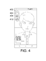
- the floating control interface 402 has a face tracking icon 406, acting as the face tracking control item mentioned above.
- the floating control interface 402 can further includes, for example, a normal mode icon 404, and a light filling icon 410, but is not limited thereto. Other icons can be added or some icons can be removed in the floating control interface 402 according to the functions that the electric device 200 requires.
- the electric device 200 When the user presses or selects the face tracking icon 406, the electric device 200 will execute following operations. Let the operations executed by the electric device A as indicated in FIGS. 5A-5E be taken for example.
- the electric device A for example, is on a video talk with an electric device B, and corresponding frames displayed on the electric device B are shown in FIGS. 6A-6E .
- FIG. 5A assume the local frame shot by the camera 206 of the electric device A is frame 502, which is further transmitted to the electric device B and displayed as frame 602 as illustrated in FIG. 6A .
- the floating control interface 402 will be displayed by superposition on the frame of the electric device A as indicated in FIG. 5A .
- the processor 204 will enter face tracking mode and the electric device A will start face tracking function, as shown in FIG. 5B .
- the electric device A will perform face tracking on the captured images to obtain at least a region of interest (ROI).
- ROI region of interest
- the ROI is enlarged, and the target frame is generated according to the enlarged ROI. That is, if the user of the electric device A selects region ROI1, the electric device A will merely enlarge the region ROI1 to form a target frame, and further transmit the target frame to the electric device B, as illustrated in FIG. 6B .
- the advantage of this method is that regardless of where the corresponding face of the region ROI1 moves to, the electric device A still can perform detection and tracking, so that the electric device B can continuously view the corresponding face of the region ROI1 without being affected by where the corresponding face of the region ROI1 moves to.
- the ROIs are enlarged, and the target frame is generated by combining the enlarged ROIs.
- the electric device A will enlarge both regions ROI1 and ROI2 to form a target frame, and further transmit the target frame to the electric device B, as illustrated in FIG. 6C .
- Each of the regions ROI1 and ROI2 may occupy a half of the region of the target frame.
- the electric device A can transmit only the user's regions of interest ROI1 and ROI2 to the electric device B, so that the user of the electric device B can clearly view the enlarged regions ROI1 and ROI2.
- the electric device A will enlarge the regions ROI1, ROI2, and ROI3 to form a target frame, and further transmit the target frame to the electric device B, as illustrated in FIG. 6D .
- Each of the regions ROI1, ROI2, and ROI3 occupies one third of the region of the target frame.
- the electric device A will enlarge the regions ROI1, ROI2, ROI3, and ROI4 to form a target frame, and further transmit the target frame to the electric device B, as illustrated in FIG. 6E .
- Each of the regions ROI1, ROI2, ROI3, and ROI4 occupies one fourth of the region of the target frame, for example.
- FIG. 7 an example of a software/hardware architecture of the electric device 200 with face tracking function is shown.
- the floating control interface 402 will be automatically executed and displayed on the screen of the electric device 200.
- the communication program is, for example, a video talk (VT) application 702
- the floating control interface 402 is, for example, a video talk enhancement (VTE) floating control interface 704.
- the VT application 702 is included in the white list of FIG. 3 , such as Skype or Line. Whether the video talk function is activated by the communication program is determined by judging if the VT application 702 is executed in the foreground and the camera 206 is already activated, which imply that the user is using the video talk function.
- the video talk enhancement (VTE) floating control interface 704 After the VT application 702 is executed in the foreground and the camera 206 is already activated (this implies that the user is using the video talk function), the video talk enhancement (VTE) floating control interface 704, for example, the floating control interface 402 shown in FIG. 4 , will be automatically executed and displayed on the screen of the electric device 200.
- VTE video talk enhancement
- the VT application 702 will call the camera service 706 to activate the camera function, and the VTE floating control interface 704 will call the VTE native application 708.
- the VTE floating control interface 704 will call the VTE native application 708 immediately.
- the VTE native application 708 informs the camera service 706 that the electric device A will enter the face tracking mode.
- the VTE native application 708 will control the camera service 706 to obtain a target frame showing only one or more than one ROI to execute the face tracking function, and show the target frame on the screen of the electric device 200 and further transmit the target frame to electric device B.
- an image is capture by a camera sensor 712, wherein after the image was processed by the image signal processor (ISP) 714, a high resolution frame FHQ is obtained.
- the resolution of the high resolution frame FHQ for example, is equivalent to the highest resolution that the camera sensor 712 can generate or larger than the resolution of the target frame.
- the resolution of the target frame is determined according to the resolution selected or used by the VT application 702.
- the high resolution frame FHQ is transmitted to the face detector 716.
- the face detector 716 detects the location of at least one face image in the high resolution frame FHQ. Then, the face detector 716 outputs the location information of the at least one face image to the face tracking engine 718.
- the face tracking engine 718 selects the location in a frame buffer according to the location information of the face image, wherein the frame buffer is for storing the frame to be shown.
- the location information of the at least one face image from the face detector 716, the location in the frame buffer determined by the face tracking engine 718, and the high resolution frame FHQ are inputted to the cutting and stitching unit 720.
- the cutting and stitching unit 720 further cuts and stitches at least one region of interest selected by the user to form a target frame FT1 accordingly.
- the face detector 716, the face tracking engine 718, and the cutting and stitching unit 720 can be realized by a graphics processing unit (GPU), a central processing unit (CPU), or other processor, for example.
- the target frame FT1 is transmitted to the camera service 706 through a camera hardware adaptation layer (HAL) 710, and is further shown on the screen of the electric device 200 by using the VTE application 702. Then, the target frame FT1 is transmitted to the electric device B at the other end of video talk by the electric device A.
- HAL camera hardware adaptation layer
- the high resolution frame FHQ is transmitted to the scaler 722, which reduces the resolution of the high resolution frame FHQ to generate a target frame FT2 with lower resolution and further transmits the target frame FT2 to the camera HAL 710. Then, the target frame FT2 is transmitted to the electric device B at the other end of video talk by the electric device A.
- the VT application 702 and the VTE floating control interface 704 are, for example, Java applications implemented by Java language.
- the camera service 706, the VTE native application 708, and the camera HAL 710 are, for example, native applications.
- the VTE native application 708 can apply Binder mechanism of Android Inter-Process Communication (IPC) mechanism.
- IPC Android Inter-Process Communication
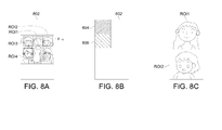
- the face detector 716 After the high resolution frame FHQ is transmitted to the face detector 716, the face detector 716 detects the location of the at least one face image in the high resolution frame FHQ. As shown in FIG. 8A , the location of the face images are detected and marked with regions of interesting ROI1, ROI2, ROI3, and ROI4. Assume two regions of interesting are selected, for example, ROI1 and ROI2 are selected by user.
- the face detector 716 outputs the location information of the face images, for example, the coordinates of ROI1 and ROI2 (such as the coordinates of the two corners in the diagonal of the rectangular ROI1 and ROI2) in the high resolution frame FHQ, to the face tracking engine 718.
- the coordinates of ROI1 and ROI2 such as the coordinates of the two corners in the diagonal of the rectangular ROI1 and ROI2 in the high resolution frame FHQ
- the face tracking engine 718 enlarges the region of at least one of ROI1 and ROI2, or scales the region of at least one of ROI1 and ROI2 to make the size of ROI1 and ROI2 to be suitable to be combined.
- the face tracking engine 718 also selects the location in a frame buffer 802 for ROI1 and ROI2, wherein the frame buffer 802 is used for storing the frame to be shown on the screen of the electric device 200.
- the face tracking engine 718 selects the location in a frame buffer 802 according to the coordinates of ROI1 and ROI2 and the scaled or enlarged sizes of the ROI1 and ROI2. Assume the face tracking engine 718 selects blocks 804 and 806 of the frame buffer 802 for ROI1 and ROI2.
- the face tracking engine 718 outputs the address of blocks 804 and 806, for example, in the frame buffer 802 to the cutting and stitching unit 720.
- the high resolution frame FHQ and the coordinates of ROI1 and ROI2 in the high resolution frame FHQ are also inputted to the cutting and stitching unit 720.
- the cutting and stitching unit 720 cuts the ROI1 and ROI2 from the high resolution frame FHQ, and stores ROI1 and ROI2 in the blocks 804 and 806 in the frame buffer 802, and outputs the image of ROI1 and ROI2 which are combined together to form the target frame FT1, which will be shown in the screen of the electric device 200, as shown in FIG. 8C .
- the resolution of the target frame FT1 (the combined image of ROI1 and ROI2) is lower than the resolution of the resolution of the high resolution frame FHQ.
- FIG. 9 another example of a target frame with three regions of interest is shown.
- the three regions of interest ROI1 ⁇ ROI3 of the target frame FT1 can be arranged in the same manner as illustrated in FIG. 6D or the manner as illustrated in FIG. 9 .
- the region of interest ROI1 which is more important than other regions of interest is shown in a larger area.
- the size of the display area for other numbers of regions of interest is determined according to parameters such as importance of region or distance to the camera.
- the electric device 200 can further provide a light filling function.
- the front flash can be controlled to perform the light filling function to change the color temperature of the captured image or change the light intensity for capturing the image.
- the color of the front flash light can be modulated to change the color temperature of the captured frame or the intensity of the front flash light can be modulated to change the light intensity for capturing the image.
- the electric device 200 can provide pan focus function or the camera 206 can focus on the objects in the distance of 0.5m to 2.5m from the electric device 200. Therefore, the image of the objects, for example, the faces, in the distance of 0.5m to 2.5m can be clear even the objects are moving, which is helpful to the fact tracking function.
- the important region of interest may relate to the face image disclosed above or other objects or things the user may have interest in.
- the above embodiments are exemplified by the Android operating system, the invention is not limited thereto and can also be used in other operating systems.
- an non-transitory storage media for storing a program code is provided.
- the program code is executed by the electric device 200, the electric device 200 performs the method for performing the face tracking function described above.
- the face tracking function and/or the function of enlarging and stitching important regions of interest to form a target frame can be achieved without having to modifying the programming code of the VT application 702 (such as Skpye and Line), especially when the VT application 702 does not support the foresaid functions. That is, by means of the VTE floating control interface 704, the VTE native application 708, the face detector 716, the face tracking engine 718, and the cutting and stitching unit 720 provided by original equipment manufacturers (OEM), the video talk application software included in the white list can be equipped with face tracking function and/or capable of enlarging and stitching regions of interest into a new target frame.
- OEM original equipment manufacturers
- VT application 702 such as Skype and Line
- the above objects can be achieved to provide the user with more video talk functions, improve the quality of video talk, achieve a better experience of use, and increase the market competitiveness for products.
Landscapes
- Engineering & Computer Science (AREA)
- Multimedia (AREA)
- Signal Processing (AREA)
- Theoretical Computer Science (AREA)
- Physics & Mathematics (AREA)
- General Physics & Mathematics (AREA)
- Human Computer Interaction (AREA)
- Health & Medical Sciences (AREA)
- General Health & Medical Sciences (AREA)
- Oral & Maxillofacial Surgery (AREA)
- Computer Vision & Pattern Recognition (AREA)
- Studio Devices (AREA)
- Two-Way Televisions, Distribution Of Moving Picture Or The Like (AREA)
- Telephone Function (AREA)
Description
- This application claims the benefit of
U.S. Provisional Application Serial No. 62/026,033, filed July 18, 2014 - The disclosure relates in general to a method for performing a face tracking function and an electric device having the same, and more particularly to a method for performing a face tracking function and an electric device having the same under a video call.
- In recent years, the resolution of the front camera of the electric device is getting higher and higher, and the use of video talk has become more and more popular. Therefore, how to provide the user with a diversified application with the video talk is emphasized by the industry.
- According to one embodiment, a method for performing a performing a face tracking function in an electric device is provided. The electric device has a touch panel, a camera, and a processor. The method includes the following steps. A touch signal is receiving by the touch panel. Under a video call, a face tracking mode is entered based on the touch signal by the processor. Face tracking is performed on a captured frame from the camera to obtain at least one region of interesting (ROI) of the captured frame by the processor, each of the ROI having an image of a face. A target frame is generated by combining the at least one ROI by the processor. The target frame is transmitted to another electric device by the processor, so that the target frame is shown on the another electric device as a video talk frame.
- According to another embodiment, an electric device for performing a face tracking function is provided. The electric device includes a touch panel, a camera, and a processor. The touch panel is for receiving a touch signal. The camera is for capturing a frame. The processor is for entering a face tracking mode based on the touch signal under a video call, and performing face tracking on the captured frame from the camera to obtain at least one ROI of the captured frame, each of the ROI having an image of a face. The processor is further for generating a target frame by combining the at least one ROI, and for transmitting the target frame to another electric device, so that the target frame is shown on the another electric device as a video talk frame.
- According to another embodiment, a non-transitory storage media for storing a program code is provided. When the program code is executed by an electric device, the electric device performs a method for performing a face tracking function. The electric device has a touch panel, a camera, and a processor. The method includes following steps. A touch signal is received by the touch panel. Under a video call, a face tracking mode is entered based on the touch signal by the processor. Face tracking on a captured frame from the camera is performed to obtain at least one region of interesting (ROI) of the captured frame by the processor, each of the ROI having an image of a face. A target frame is generated by combining the at least one ROI by the processor. The target frame is transmitted to another electric device by the processor, so that the target frame is shown on the another electric device as a video talk frame.
-
-
FIG. 1 shows a flow chart for a method for performing a face tracking function in an electric device according to an embodiment of the invention. -
FIG. 2 shows the block diagram of the electric device. -
FIG. 3 shows an example of the white list. -
FIG. 4 shows an example of the floating control interface of the electric device according to an embodiment of the invention. -
FIGS. 5A-5E shows the corresponding frames displayed on the electric device A. -
FIGS. 6A-6E shows the corresponding frames displayed on the electric device B. -
FIG. 7 shows an example of a software/hardware architecture of the electric device with face tracking function. -
FIG. 8A to FIG. 8C illustrate the operation of the face detector, the face tracking engine, and the cutting and stitching unit. -
FIG. 9 shows another example of a target frame with three regions of interest. - In the following detailed description, for purposes of explanation, numerous specific details are set forth in order to provide a thorough understanding of the disclosed embodiments. It will be apparent, however, that one or more embodiments may be practiced without these specific details. In other instances, well-known structures and devices are schematically shown in order to simplify the drawing.
-
FIG. 1 shows a flow chart for a method for performing a face tracking function in an electric device according to an embodiment of the invention. The block diagram of theelectric device 200 is shown inFIG. 2 . Theelectric device 200 has atouch panel 202, aprocessor 204, and acamera 206. The method includes the following steps. First, instep 102, thetouch panel 202 receives a touch signal. Second, instep 104, under a video call, theprocessor 204 enters a face tracking mode based on the touch signal. Next, instep 106, theprocessor 204 performs face tracking on a captured frame from thecamera 206 to obtain at least one region of interesting (ROI) of the captured frame. Each of the ROI has an image of a face. After that, instep 108, theprocessor 204 generates a target frame by combining the at least one ROI. Then, instep 110, theprocessor 204 transmits the target frame to another electric device, so that the target frame is shown on the another electric device as a video talk frame. - Therefore, even if the application currently executed by the
electric device 200 for the video call do not provide the face tracking function, theelectric device 200 according to the embodiment can perform the face tracking function and transmits the target frame to the another electric device as a video talk frame. That is, the target frame can replace the frame of the video talk, and the target frame can be transmitted by the same way as a frame for video talk to another electric device to achieve the face tracking function. - When the
electric device 200 runs a communicating program to perform video talk with another electric device, thetouch panel 202 can further display a floating control interface. The floating control interface has a face tracking control item. When the face tracking control item is selected, thetouch panel 202 will receive the touch signal, and theprocessor 204 correspondingly enters the face tracking function based on the touch signal under a video call. - Furthermore, the
touch panel 202 has the ability of touching and/or displaying. Theelectric device 200 can have a display (not shown) if thetouch panel 202 does not have the ability of displaying. Frames can be displayed on the screen of thetouch panel 202 or on the screen of the display. Theelectric device 200 can further have acommunication module 208 for communicate with other electric device through wireless communication or through Internet. - The
electric device 200 can be a mobile device, such as a smartphone or tablet PC. The operating system of theelectric device 200 is, for example, Android operating system. Theprocessor 204 determines whether theelectric device 200 is performing the video talk by judging whether the communicating program for the video call is performed in foreground and whether thecamera 206 is activated. When the communicating program for the video call is performed in foreground and thecamera 206 is activated, theprocessor 204 determines that theelectric device 200 is performing the video talk. The communicating program can be one of the applications which can perform video calls listed in a white list. The white list also contains other candidate communication programs.FIG. 3 shows an example of the white list. - If the application currently executed by the
electric device 200 in the foreground is included in a white list ofFIG. 3 and thecamera 206 is already activated, it is determined that theelectric device 200 is performing the video talk, and the floating control interface will be displayed on the screen. The floating control interface is an independent application from the communication programs and the floating control interface is not contained in the white list. The floating control interface can be used as a user operating interface. - Referring to
FIG. 4 , an example of the floating control interface of theelectric device 200 according to an embodiment of the invention is shown. The floatingcontrol interface 402 has aface tracking icon 406, acting as the face tracking control item mentioned above. The floatingcontrol interface 402 can further includes, for example, anormal mode icon 404, and alight filling icon 410, but is not limited thereto. Other icons can be added or some icons can be removed in the floatingcontrol interface 402 according to the functions that theelectric device 200 requires. - When the user presses or selects the
face tracking icon 406, theelectric device 200 will execute following operations. Let the operations executed by the electric device A as indicated inFIGS. 5A-5E be taken for example. The electric device A, for example, is on a video talk with an electric device B, and corresponding frames displayed on the electric device B are shown inFIGS. 6A-6E . Referring toFIG. 5A , assume the local frame shot by thecamera 206 of the electric device A isframe 502, which is further transmitted to the electric device B and displayed asframe 602 as illustrated inFIG. 6A . - If the application currently executed in the foreground of the electric device A is included in the white list of
FIG. 3 and thecamera 206 is already activated, the floatingcontrol interface 402 will be displayed by superposition on the frame of the electric device A as indicated inFIG. 5A . When the user of the electric device A selects theface tracking icon 406 of the floatingcontrol interface 402, theprocessor 204 will enter face tracking mode and the electric device A will start face tracking function, as shown inFIG. 5B . The electric device A will perform face tracking on the captured images to obtain at least a region of interest (ROI). - If one ROI is obtained, the ROI is enlarged, and the target frame is generated according to the enlarged ROI. That is, if the user of the electric device A selects region ROI1, the electric device A will merely enlarge the region ROI1 to form a target frame, and further transmit the target frame to the electric device B, as illustrated in
FIG. 6B . The advantage of this method is that regardless of where the corresponding face of the region ROI1 moves to, the electric device A still can perform detection and tracking, so that the electric device B can continuously view the corresponding face of the region ROI1 without being affected by where the corresponding face of the region ROI1 moves to. - If more than one ROIs are obtained, the ROIs are enlarged, and the target frame is generated by combining the enlarged ROIs. For example, if the user of the electric device A selects regions ROI1 and ROI2, the electric device A will enlarge both regions ROI1 and ROI2 to form a target frame, and further transmit the target frame to the electric device B, as illustrated in
FIG. 6C . Each of the regions ROI1 and ROI2 may occupy a half of the region of the target frame. Thus, the electric device A can transmit only the user's regions of interest ROI1 and ROI2 to the electric device B, so that the user of the electric device B can clearly view the enlarged regions ROI1 and ROI2. - If the user of the electric device A selects regions ROI1, ROI2, and ROI3, the electric device A will enlarge the regions ROI1, ROI2, and ROI3 to form a target frame, and further transmit the target frame to the electric device B, as illustrated in
FIG. 6D . Each of the regions ROI1, ROI2, and ROI3 occupies one third of the region of the target frame. If the user of the electric device A selects regions ROI1, ROI2, ROI3, and ROI4, the electric device A will enlarge the regions ROI1, ROI2, ROI3, and ROI4 to form a target frame, and further transmit the target frame to the electric device B, as illustrated inFIG. 6E . Each of the regions ROI1, ROI2, ROI3, and ROI4 occupies one fourth of the region of the target frame, for example. - Referring to
FIG. 7 , an example of a software/hardware architecture of theelectric device 200 with face tracking function is shown. After the video talk function is activated by the communication program, the floatingcontrol interface 402 will be automatically executed and displayed on the screen of theelectric device 200. The communication program is, for example, a video talk (VT)application 702, and the floatingcontrol interface 402 is, for example, a video talk enhancement (VTE) floatingcontrol interface 704. TheVT application 702 is included in the white list ofFIG. 3 , such as Skype or Line. Whether the video talk function is activated by the communication program is determined by judging if theVT application 702 is executed in the foreground and thecamera 206 is already activated, which imply that the user is using the video talk function. After theVT application 702 is executed in the foreground and thecamera 206 is already activated (this implies that the user is using the video talk function), the video talk enhancement (VTE) floatingcontrol interface 704, for example, the floatingcontrol interface 402 shown inFIG. 4 , will be automatically executed and displayed on the screen of theelectric device 200. - During the video talk under the normal mode, the
VT application 702 will call thecamera service 706 to activate the camera function, and the VTE floatingcontrol interface 704 will call the VTEnative application 708. When the user of the electric device A selects theface tracking icon 406 of the floatingcontrol interface 402, the electric device A will start face tracking function. Meanwhile, the VTE floatingcontrol interface 704 will call the VTEnative application 708 immediately. Then, the VTEnative application 708 informs thecamera service 706 that the electric device A will enter the face tracking mode. The VTEnative application 708 will control thecamera service 706 to obtain a target frame showing only one or more than one ROI to execute the face tracking function, and show the target frame on the screen of theelectric device 200 and further transmit the target frame to electric device B. - Details of the method of generating the target frame are described below. Firstly, an image is capture by a
camera sensor 712, wherein after the image was processed by the image signal processor (ISP) 714, a high resolution frame FHQ is obtained. The resolution of the high resolution frame FHQ, for example, is equivalent to the highest resolution that thecamera sensor 712 can generate or larger than the resolution of the target frame. The resolution of the target frame is determined according to the resolution selected or used by theVT application 702. - Next, when the user selects the face tracking function, the high resolution frame FHQ is transmitted to the
face detector 716. Theface detector 716 detects the location of at least one face image in the high resolution frame FHQ. Then, theface detector 716 outputs the location information of the at least one face image to theface tracking engine 718. Theface tracking engine 718 selects the location in a frame buffer according to the location information of the face image, wherein the frame buffer is for storing the frame to be shown. The location information of the at least one face image from theface detector 716, the location in the frame buffer determined by theface tracking engine 718, and the high resolution frame FHQ are inputted to the cutting andstitching unit 720. The cutting andstitching unit 720 further cuts and stitches at least one region of interest selected by the user to form a target frame FT1 accordingly. Theface detector 716, theface tracking engine 718, and the cutting andstitching unit 720 can be realized by a graphics processing unit (GPU), a central processing unit (CPU), or other processor, for example. - Then, the target frame FT1 is transmitted to the
camera service 706 through a camera hardware adaptation layer (HAL) 710, and is further shown on the screen of theelectric device 200 by using theVTE application 702. Then, the target frame FT1 is transmitted to the electric device B at the other end of video talk by the electric device A. - If the user only selects a normal mode instead of the face tracking function, the high resolution frame FHQ is transmitted to the
scaler 722, which reduces the resolution of the high resolution frame FHQ to generate a target frame FT2 with lower resolution and further transmits the target frame FT2 to thecamera HAL 710. Then, the target frame FT2 is transmitted to the electric device B at the other end of video talk by the electric device A. - The
VT application 702 and the VTE floatingcontrol interface 704 are, for example, Java applications implemented by Java language. Thecamera service 706, the VTEnative application 708, and thecamera HAL 710 are, for example, native applications. The VTEnative application 708 can apply Binder mechanism of Android Inter-Process Communication (IPC) mechanism. The above architecture can be implemented under the Android operating system or other operating systems. - The operation of the
face detector 716, theface tracking engine 718, and the cutting andstitching unit 720 will be explained in more detailed with the example shown inFIG. 8A to FIG. 8C . After the high resolution frame FHQ is transmitted to theface detector 716, theface detector 716 detects the location of the at least one face image in the high resolution frame FHQ. As shown inFIG. 8A , the location of the face images are detected and marked with regions of interesting ROI1, ROI2, ROI3, and ROI4. Assume two regions of interesting are selected, for example, ROI1 and ROI2 are selected by user. Then, theface detector 716 outputs the location information of the face images, for example, the coordinates of ROI1 and ROI2 (such as the coordinates of the two corners in the diagonal of the rectangular ROI1 and ROI2) in the high resolution frame FHQ, to theface tracking engine 718. - As shown in
FIG. 8B , theface tracking engine 718 enlarges the region of at least one of ROI1 and ROI2, or scales the region of at least one of ROI1 and ROI2 to make the size of ROI1 and ROI2 to be suitable to be combined. Theface tracking engine 718 also selects the location in aframe buffer 802 for ROI1 and ROI2, wherein theframe buffer 802 is used for storing the frame to be shown on the screen of theelectric device 200. Theface tracking engine 718 selects the location in aframe buffer 802 according to the coordinates of ROI1 and ROI2 and the scaled or enlarged sizes of the ROI1 and ROI2. Assume theface tracking engine 718 selectsblocks frame buffer 802 for ROI1 and ROI2. Then, theface tracking engine 718 outputs the address ofblocks frame buffer 802 to the cutting andstitching unit 720. The high resolution frame FHQ and the coordinates of ROI1 and ROI2 in the high resolution frame FHQ are also inputted to the cutting andstitching unit 720. According to the coordinates of ROI1 and ROI2 in the high resolution frame FHQ, the cutting andstitching unit 720 cuts the ROI1 and ROI2 from the high resolution frame FHQ, and stores ROI1 and ROI2 in theblocks frame buffer 802, and outputs the image of ROI1 and ROI2 which are combined together to form the target frame FT1, which will be shown in the screen of theelectric device 200, as shown inFIG. 8C . The resolution of the target frame FT1 (the combined image of ROI1 and ROI2) is lower than the resolution of the resolution of the high resolution frame FHQ. - Referring to
FIG. 9 , another example of a target frame with three regions of interest is shown. When the user selects three regions of interest ROI1∼ROI3, the three regions of interest ROI1∼ROI3 of the target frame FT1 can be arranged in the same manner as illustrated inFIG. 6D or the manner as illustrated inFIG. 9 . InFIG. 9 , the region of interest ROI1 which is more important than other regions of interest is shown in a larger area. The size of the display area for other numbers of regions of interest is determined according to parameters such as importance of region or distance to the camera. - Besides, the
electric device 200 can further provide a light filling function. According to the position of the face(s) or the brightness in the environment, the front flash can be controlled to perform the light filling function to change the color temperature of the captured image or change the light intensity for capturing the image. For example, the color of the front flash light can be modulated to change the color temperature of the captured frame or the intensity of the front flash light can be modulated to change the light intensity for capturing the image. - Furthermore, the
electric device 200 can provide pan focus function or thecamera 206 can focus on the objects in the distance of 0.5m to 2.5m from theelectric device 200. Therefore, the image of the objects, for example, the faces, in the distance of 0.5m to 2.5m can be clear even the objects are moving, which is helpful to the fact tracking function. - The important region of interest may relate to the face image disclosed above or other objects or things the user may have interest in. Although the above embodiments are exemplified by the Android operating system, the invention is not limited thereto and can also be used in other operating systems.
- Furthermore, according to one embodiment, an non-transitory storage media for storing a program code is provided. When the program code is executed by the
electric device 200, theelectric device 200 performs the method for performing the face tracking function described above. - By using the VTE floating
control interface 704, the face tracking function and/or the function of enlarging and stitching important regions of interest to form a target frame can be achieved without having to modifying the programming code of the VT application 702 (such as Skpye and Line), especially when theVT application 702 does not support the foresaid functions. That is, by means of the VTE floatingcontrol interface 704, the VTEnative application 708, theface detector 716, theface tracking engine 718, and the cutting andstitching unit 720 provided by original equipment manufacturers (OEM), the video talk application software included in the white list can be equipped with face tracking function and/or capable of enlarging and stitching regions of interest into a new target frame. Without having to modify the programming code of the communication program (VT application 702) (such as Skype and Line) for video talk, the above objects can be achieved to provide the user with more video talk functions, improve the quality of video talk, achieve a better experience of use, and increase the market competitiveness for products. - It will be apparent to those skilled in the art that various modifications and variations can be made to the disclosed embodiments. It is intended that the specification and examples be considered as exemplary only, with a true scope of the disclosure being indicated by the following claims and their equivalents.
Claims (15)
- A method for performing a face tracking function in an electric device, the electric device having a touch panel, a camera, and a processor, the method comprising:receiving a touch signal by the touch panel;under a video call, entering a face tracking mode based on the touch signal by the processor;performing face tracking on a captured frame from the camera to obtain at least one region of interesting (ROI) of the captured frame by the processor, each of the ROI having an image of a face;generating a target frame by combining the at least one ROI by the processor; andtransmitting the target frame to another electric device by the processor, so that the target frame is shown on the another electric device as a video talk frame.
- The method according to claim 1, further comprising displaying a floating control interface by the touch panel when the electric device runs a communicating program to perform the video talk with the another electric device, and the floating control interface has a face tracking control item;
wherein the receiving step comprising receiving the touch signal by the touch panel when the face tracking control item is selected. - The method according to claim 2, further comprising:determining whether the electric device is performing the video talk by judging whether the communicating program is performed in foreground and whether the camera is activated, wherein the communicating program is listed in a white list.
- The method according to claim 3, wherein a plurality of candidate communication programs are listed in the white list.
- The method according to claim 1, wherein in the performing step, one ROI is obtained;
Wherein the generating step comprises enlarging the ROI, and the target frame is generated according to the enlarged ROI. - The method according to claim 1, wherein in the performing step, more than one ROIs are obtained, the generating step comprises enlarging the ROIs, and the target frame is generated by combining the enlarged ROIs.
- The method according to claim 1, wherein before the step of performing face tracking, the method further comprises performing face detecting on the captured frame from the camera to determining the location of the at least one face in the captured frame.
- A electric device for performing a face tracking function, the electric device comprising:a touch panel, for receiving a touch signal;a camera, for capturing a frame; anda processor, for entering a face tracking mode based on the touch signal under a video call, and performing face tracking on the captured frame from the camera to obtain at least one ROI of the captured frame, each of the ROI having an image of a face;wherein the processor is further for generating a target frame by combining the at least one ROI, and for transmitting the target frame to another electric device, so that the target frame is shown on the another electric device as a video talk frame.
- The device according to claim 8, further the touch panel further displays a floating control interface when the electric device runs a communicating program to perform the video talk with the another electric device, and the floating control interface has a face tracking control item;
wherein the touch panel receives the touch signal when the face tracking control item is selected. - The device according to claim 9, wherein the processor further determine whether the electric device is performing the video talk by judging whether the communicating program is performed in foreground and whether the camera is activated, wherein the communicating program is listed in a white list.
- The device according to claim 10, wherein a plurality of candidate communication programs are listed in the white list.
- The device according to claim 8, wherein the at least one ROI comprises one ROI, the processor further enlarges the ROI, and the target frame is generated according to the enlarged ROI.
- The device according to claim 8, wherein the at least one ROI comprises more than one ROIs, the processor further enlarges the ROIs, and the target frame is generated by combining the enlarged ROIs.
- The device according to claim 8, wherein the processor further performs face detecting on the captured frame from the camera to determining the location of the at least one face in the captured frame before the processor performs face tracking.
- A non-transitory storage media for storing a program code, wherein when the program code is executed by an electric device, the electric device performs a method for performing a face tracking function, the electric device has a touch panel, a camera, and a processor, the method comprises:receiving a touch signal by the touch panel;under a video call, entering a face tracking mode based on the touch signal by the processor;performing face tracking on a captured frame from the camera to obtain at least one region of interesting (ROI) of the captured frame by the processor, each of the ROI having an image of a face;generating a target frame by combining the at least one ROI by the processor; andtransmitting the target frame to another electric device by the processor, so that the target frame is shown on the another electric device as a video talk frame.
Applications Claiming Priority (2)
| Application Number | Priority Date | Filing Date | Title |
|---|---|---|---|
| US201462026033P | 2014-07-18 | 2014-07-18 | |
| US14/748,974 US9858470B2 (en) | 2014-07-18 | 2015-06-24 | Method for performing a face tracking function and an electric device having the same |
Publications (3)
| Publication Number | Publication Date |
|---|---|
| EP2975842A2 true EP2975842A2 (en) | 2016-01-20 |
| EP2975842A3 EP2975842A3 (en) | 2016-05-11 |
| EP2975842B1 EP2975842B1 (en) | 2019-06-12 |
Family
ID=53785444
Family Applications (1)
| Application Number | Title | Priority Date | Filing Date |
|---|---|---|---|
| EP15177213.4A Active EP2975842B1 (en) | 2014-07-18 | 2015-07-17 | Method for performing a face tracking function and an electric device having the same |
Country Status (2)
| Country | Link |
|---|---|
| US (1) | US9858470B2 (en) |
| EP (1) | EP2975842B1 (en) |
Cited By (1)
| Publication number | Priority date | Publication date | Assignee | Title |
|---|---|---|---|---|
| CN107071292A (en) * | 2017-03-10 | 2017-08-18 | 深圳市金立通信设备有限公司 | A kind of light compensation method and terminal |
Families Citing this family (13)
| Publication number | Priority date | Publication date | Assignee | Title |
|---|---|---|---|---|
| US11553157B2 (en) | 2016-10-10 | 2023-01-10 | Hyperconnect Inc. | Device and method of displaying images |
| KR101932844B1 (en) | 2017-04-17 | 2018-12-27 | 주식회사 하이퍼커넥트 | Device and method of making video calls and method of mediating video calls |
| KR102132341B1 (en) * | 2017-12-27 | 2020-07-09 | 주식회사 하이퍼커넥트 | Terminal and server providing a video call service |
| KR102044242B1 (en) * | 2017-12-27 | 2019-11-13 | 주식회사 하이퍼커넥트 | Terminal and server providing a video call service |
| JP7075995B2 (en) | 2018-06-07 | 2022-05-26 | マクセル株式会社 | Mobile information terminal |
| KR102282963B1 (en) | 2019-05-10 | 2021-07-29 | 주식회사 하이퍼커넥트 | Mobile, server and operating method thereof |
| US11263467B2 (en) * | 2019-05-15 | 2022-03-01 | Apical Limited | Image processing |
| KR102311603B1 (en) | 2019-10-01 | 2021-10-13 | 주식회사 하이퍼커넥트 | Mobile and operating method thereof |
| CN112825116B (en) * | 2019-11-20 | 2024-04-09 | 北京眼神智能科技有限公司 | Method, device, medium and equipment for detecting and tracking human face of monitoring video image |
| KR102293422B1 (en) | 2020-01-31 | 2021-08-26 | 주식회사 하이퍼커넥트 | Mobile and operating method thereof |
| KR20210115442A (en) | 2020-03-13 | 2021-09-27 | 주식회사 하이퍼커넥트 | Report evaluation device and operating method thereof |
| US12010457B2 (en) | 2021-04-16 | 2024-06-11 | Hyperconnect Inc. | Methods, systems, and computer program products for providing video call service |
| JP7693746B2 (en) * | 2022-05-16 | 2025-06-17 | マクセル株式会社 | Portable information terminal and method |
Family Cites Families (17)
| Publication number | Priority date | Publication date | Assignee | Title |
|---|---|---|---|---|
| KR100628756B1 (en) | 2004-09-07 | 2006-09-29 | 엘지전자 주식회사 | Apparatus and method for providing an effect screen during a video call with a mobile terminal |
| US8019175B2 (en) * | 2005-03-09 | 2011-09-13 | Qualcomm Incorporated | Region-of-interest processing for video telephony |
| RU2008105303A (en) * | 2005-07-13 | 2009-08-20 | Конинклейке Филипс Электроникс Н.В. (Nl) | METHOD AND DEVICE FOR PROCESSING WITH TEMPORARY INCREASING VIDEO CONVERSION |
| US8019170B2 (en) | 2005-10-05 | 2011-09-13 | Qualcomm, Incorporated | Video frame motion-based automatic region-of-interest detection |
| US8265349B2 (en) * | 2006-02-07 | 2012-09-11 | Qualcomm Incorporated | Intra-mode region-of-interest video object segmentation |
| US9344612B2 (en) * | 2006-02-15 | 2016-05-17 | Kenneth Ira Ritchey | Non-interference field-of-view support apparatus for a panoramic facial sensor |
| CN201213278Y (en) | 2008-07-02 | 2009-03-25 | 希姆通信息技术(上海)有限公司 | Intelligent human face tracing device taking image by mobile phone |
| US8237771B2 (en) * | 2009-03-26 | 2012-08-07 | Eastman Kodak Company | Automated videography based communications |
| TWI389019B (en) | 2009-06-17 | 2013-03-11 | Au Optronics Corp | Touch operation method and operation method of electronic device |
| NO332170B1 (en) * | 2009-10-14 | 2012-07-16 | Cisco Systems Int Sarl | Camera control device and method |
| KR101764372B1 (en) | 2011-04-19 | 2017-08-03 | 삼성전자주식회사 | Apparatus and method for compositing image in a portable terminal |
| US8971574B2 (en) | 2011-11-22 | 2015-03-03 | Ulsee Inc. | Orientation correction method for electronic device used to perform facial recognition and electronic device thereof |
| WO2014014238A1 (en) | 2012-07-17 | 2014-01-23 | Samsung Electronics Co., Ltd. | System and method for providing image |
| KR102091137B1 (en) | 2012-07-17 | 2020-03-20 | 삼성전자주식회사 | System and method for rpoviding image |
| KR20140034574A (en) | 2012-09-12 | 2014-03-20 | 삼성전자주식회사 | Method and apparatus for displaying camera preview screen in a portable terminal |
| CN103310411B (en) | 2012-09-25 | 2017-04-12 | 中兴通讯股份有限公司 | Image local reinforcement method and device |
| KR101800617B1 (en) | 2013-01-02 | 2017-12-20 | 삼성전자주식회사 | Display apparatus and Method for video calling thereof |
-
2015
- 2015-06-24 US US14/748,974 patent/US9858470B2/en active Active
- 2015-07-17 EP EP15177213.4A patent/EP2975842B1/en active Active
Non-Patent Citations (1)
| Title |
|---|
| None |
Cited By (1)
| Publication number | Priority date | Publication date | Assignee | Title |
|---|---|---|---|---|
| CN107071292A (en) * | 2017-03-10 | 2017-08-18 | 深圳市金立通信设备有限公司 | A kind of light compensation method and terminal |
Also Published As
| Publication number | Publication date |
|---|---|
| EP2975842B1 (en) | 2019-06-12 |
| US20160019412A1 (en) | 2016-01-21 |
| US9858470B2 (en) | 2018-01-02 |
| EP2975842A3 (en) | 2016-05-11 |
Similar Documents
| Publication | Publication Date | Title |
|---|---|---|
| EP2975842B1 (en) | Method for performing a face tracking function and an electric device having the same | |
| KR102875191B1 (en) | Assistance for orienting the camera at different zoom levels | |
| US9484005B2 (en) | Trimming content for projection onto a target | |
| US10585473B2 (en) | Visual gestures | |
| CA2941143C (en) | System and method for multi-focus imaging | |
| TWI545508B (en) | Method for performing a face tracking function and an electric device having the same | |
| US10055081B2 (en) | Enabling visual recognition of an enlarged image | |
| US9742995B2 (en) | Receiver-controlled panoramic view video share | |
| KR20210084373A (en) | Method and device to display background image | |
| US9609270B2 (en) | Method for performing a video talk enhancement function and an electric device having the same | |
| JP6948848B2 (en) | Marking scanning system and method controlled by line-of-sight detection | |
| WO2014054249A1 (en) | Information processing apparatus, information processing method, and program | |
| JP6587081B2 (en) | Method and system for assisting a user in capturing an image or video | |
| AU2014221567A1 (en) | Apparatus and method for processing an image in device | |
| US20150363953A1 (en) | Image switching method and device | |
| KR102082365B1 (en) | Method for image processing and an electronic device thereof | |
| WO2018045592A1 (en) | Image shooting method and device, and terminal | |
| KR102561274B1 (en) | Display apparatus and controlling method thereof | |
| JP6483661B2 (en) | Imaging control apparatus, imaging control method, and program | |
| JP2014048775A (en) | Apparatus and program for identifying position gazed | |
| KR20190100126A (en) | Method for transmitting for image and an electronic device thereof | |
| JP2015049836A (en) | Portable terminal |
Legal Events
| Date | Code | Title | Description |
|---|---|---|---|
| PUAI | Public reference made under article 153(3) epc to a published international application that has entered the european phase |
Free format text: ORIGINAL CODE: 0009012 |
|
| 17P | Request for examination filed |
Effective date: 20150717 |
|
| AK | Designated contracting states |
Kind code of ref document: A2 Designated state(s): AL AT BE BG CH CY CZ DE DK EE ES FI FR GB GR HR HU IE IS IT LI LT LU LV MC MK MT NL NO PL PT RO RS SE SI SK SM TR |
|
| AX | Request for extension of the european patent |
Extension state: BA ME |
|
| PUAL | Search report despatched |
Free format text: ORIGINAL CODE: 0009013 |
|
| AK | Designated contracting states |
Kind code of ref document: A3 Designated state(s): AL AT BE BG CH CY CZ DE DK EE ES FI FR GB GR HR HU IE IS IT LI LT LU LV MC MK MT NL NO PL PT RO RS SE SI SK SM TR |
|
| AX | Request for extension of the european patent |
Extension state: BA ME |
|
| RIC1 | Information provided on ipc code assigned before grant |
Ipc: G06K 9/00 20060101ALI20160406BHEP Ipc: H04N 7/14 20060101AFI20160406BHEP |
|
| RBV | Designated contracting states (corrected) |
Designated state(s): AL AT BE BG CH CY CZ DE DK EE ES FI FR GB GR HR HU IE IS IT LI LT LU LV MC MK MT NL NO PL PT RO RS SE SI SK SM TR |
|
| STAA | Information on the status of an ep patent application or granted ep patent |
Free format text: STATUS: EXAMINATION IS IN PROGRESS |
|
| 17Q | First examination report despatched |
Effective date: 20170210 |
|
| GRAP | Despatch of communication of intention to grant a patent |
Free format text: ORIGINAL CODE: EPIDOSNIGR1 |
|
| STAA | Information on the status of an ep patent application or granted ep patent |
Free format text: STATUS: GRANT OF PATENT IS INTENDED |
|
| INTG | Intention to grant announced |
Effective date: 20190109 |
|
| GRAS | Grant fee paid |
Free format text: ORIGINAL CODE: EPIDOSNIGR3 |
|
| GRAA | (expected) grant |
Free format text: ORIGINAL CODE: 0009210 |
|
| STAA | Information on the status of an ep patent application or granted ep patent |
Free format text: STATUS: THE PATENT HAS BEEN GRANTED |
|
| AK | Designated contracting states |
Kind code of ref document: B1 Designated state(s): AL AT BE BG CH CY CZ DE DK EE ES FI FR GB GR HR HU IE IS IT LI LT LU LV MC MK MT NL NO PL PT RO RS SE SI SK SM TR |
|
| REG | Reference to a national code |
Ref country code: GB Ref legal event code: FG4D |
|
| REG | Reference to a national code |
Ref country code: CH Ref legal event code: EP |
|
| REG | Reference to a national code |
Ref country code: AT Ref legal event code: REF Ref document number: 1144106 Country of ref document: AT Kind code of ref document: T Effective date: 20190615 |
|
| REG | Reference to a national code |
Ref country code: DE Ref legal event code: R096 Ref document number: 602015031673 Country of ref document: DE |
|
| REG | Reference to a national code |
Ref country code: IE Ref legal event code: FG4D |
|
| REG | Reference to a national code |
Ref country code: NL Ref legal event code: FP |
|
| REG | Reference to a national code |
Ref country code: LT Ref legal event code: MG4D |
|
| PG25 | Lapsed in a contracting state [announced via postgrant information from national office to epo] |
Ref country code: LT Free format text: LAPSE BECAUSE OF FAILURE TO SUBMIT A TRANSLATION OF THE DESCRIPTION OR TO PAY THE FEE WITHIN THE PRESCRIBED TIME-LIMIT Effective date: 20190612 Ref country code: HR Free format text: LAPSE BECAUSE OF FAILURE TO SUBMIT A TRANSLATION OF THE DESCRIPTION OR TO PAY THE FEE WITHIN THE PRESCRIBED TIME-LIMIT Effective date: 20190612 Ref country code: SE Free format text: LAPSE BECAUSE OF FAILURE TO SUBMIT A TRANSLATION OF THE DESCRIPTION OR TO PAY THE FEE WITHIN THE PRESCRIBED TIME-LIMIT Effective date: 20190612 Ref country code: NO Free format text: LAPSE BECAUSE OF FAILURE TO SUBMIT A TRANSLATION OF THE DESCRIPTION OR TO PAY THE FEE WITHIN THE PRESCRIBED TIME-LIMIT Effective date: 20190912 Ref country code: AL Free format text: LAPSE BECAUSE OF FAILURE TO SUBMIT A TRANSLATION OF THE DESCRIPTION OR TO PAY THE FEE WITHIN THE PRESCRIBED TIME-LIMIT Effective date: 20190612 Ref country code: FI Free format text: LAPSE BECAUSE OF FAILURE TO SUBMIT A TRANSLATION OF THE DESCRIPTION OR TO PAY THE FEE WITHIN THE PRESCRIBED TIME-LIMIT Effective date: 20190612 |
|
| PG25 | Lapsed in a contracting state [announced via postgrant information from national office to epo] |
Ref country code: BG Free format text: LAPSE BECAUSE OF FAILURE TO SUBMIT A TRANSLATION OF THE DESCRIPTION OR TO PAY THE FEE WITHIN THE PRESCRIBED TIME-LIMIT Effective date: 20190912 Ref country code: GR Free format text: LAPSE BECAUSE OF FAILURE TO SUBMIT A TRANSLATION OF THE DESCRIPTION OR TO PAY THE FEE WITHIN THE PRESCRIBED TIME-LIMIT Effective date: 20190913 Ref country code: LV Free format text: LAPSE BECAUSE OF FAILURE TO SUBMIT A TRANSLATION OF THE DESCRIPTION OR TO PAY THE FEE WITHIN THE PRESCRIBED TIME-LIMIT Effective date: 20190612 Ref country code: RS Free format text: LAPSE BECAUSE OF FAILURE TO SUBMIT A TRANSLATION OF THE DESCRIPTION OR TO PAY THE FEE WITHIN THE PRESCRIBED TIME-LIMIT Effective date: 20190612 |
|
| REG | Reference to a national code |
Ref country code: AT Ref legal event code: MK05 Ref document number: 1144106 Country of ref document: AT Kind code of ref document: T Effective date: 20190612 |
|
| PG25 | Lapsed in a contracting state [announced via postgrant information from national office to epo] |
Ref country code: SK Free format text: LAPSE BECAUSE OF FAILURE TO SUBMIT A TRANSLATION OF THE DESCRIPTION OR TO PAY THE FEE WITHIN THE PRESCRIBED TIME-LIMIT Effective date: 20190612 Ref country code: RO Free format text: LAPSE BECAUSE OF FAILURE TO SUBMIT A TRANSLATION OF THE DESCRIPTION OR TO PAY THE FEE WITHIN THE PRESCRIBED TIME-LIMIT Effective date: 20190612 Ref country code: CZ Free format text: LAPSE BECAUSE OF FAILURE TO SUBMIT A TRANSLATION OF THE DESCRIPTION OR TO PAY THE FEE WITHIN THE PRESCRIBED TIME-LIMIT Effective date: 20190612 Ref country code: PT Free format text: LAPSE BECAUSE OF FAILURE TO SUBMIT A TRANSLATION OF THE DESCRIPTION OR TO PAY THE FEE WITHIN THE PRESCRIBED TIME-LIMIT Effective date: 20191014 Ref country code: AT Free format text: LAPSE BECAUSE OF FAILURE TO SUBMIT A TRANSLATION OF THE DESCRIPTION OR TO PAY THE FEE WITHIN THE PRESCRIBED TIME-LIMIT Effective date: 20190612 Ref country code: EE Free format text: LAPSE BECAUSE OF FAILURE TO SUBMIT A TRANSLATION OF THE DESCRIPTION OR TO PAY THE FEE WITHIN THE PRESCRIBED TIME-LIMIT Effective date: 20190612 |
|
| PG25 | Lapsed in a contracting state [announced via postgrant information from national office to epo] |
Ref country code: IS Free format text: LAPSE BECAUSE OF FAILURE TO SUBMIT A TRANSLATION OF THE DESCRIPTION OR TO PAY THE FEE WITHIN THE PRESCRIBED TIME-LIMIT Effective date: 20191012 Ref country code: SM Free format text: LAPSE BECAUSE OF FAILURE TO SUBMIT A TRANSLATION OF THE DESCRIPTION OR TO PAY THE FEE WITHIN THE PRESCRIBED TIME-LIMIT Effective date: 20190612 Ref country code: ES Free format text: LAPSE BECAUSE OF FAILURE TO SUBMIT A TRANSLATION OF THE DESCRIPTION OR TO PAY THE FEE WITHIN THE PRESCRIBED TIME-LIMIT Effective date: 20190612 Ref country code: IT Free format text: LAPSE BECAUSE OF FAILURE TO SUBMIT A TRANSLATION OF THE DESCRIPTION OR TO PAY THE FEE WITHIN THE PRESCRIBED TIME-LIMIT Effective date: 20190612 |
|
| REG | Reference to a national code |
Ref country code: CH Ref legal event code: PL |
|
| REG | Reference to a national code |
Ref country code: DE Ref legal event code: R097 Ref document number: 602015031673 Country of ref document: DE |
|
| PG25 | Lapsed in a contracting state [announced via postgrant information from national office to epo] |
Ref country code: MC Free format text: LAPSE BECAUSE OF FAILURE TO SUBMIT A TRANSLATION OF THE DESCRIPTION OR TO PAY THE FEE WITHIN THE PRESCRIBED TIME-LIMIT Effective date: 20190612 Ref country code: TR Free format text: LAPSE BECAUSE OF FAILURE TO SUBMIT A TRANSLATION OF THE DESCRIPTION OR TO PAY THE FEE WITHIN THE PRESCRIBED TIME-LIMIT Effective date: 20190612 |
|
| REG | Reference to a national code |
Ref country code: BE Ref legal event code: MM Effective date: 20190731 |
|
| PLBE | No opposition filed within time limit |
Free format text: ORIGINAL CODE: 0009261 |
|
| STAA | Information on the status of an ep patent application or granted ep patent |
Free format text: STATUS: NO OPPOSITION FILED WITHIN TIME LIMIT |
|
| PG25 | Lapsed in a contracting state [announced via postgrant information from national office to epo] |
Ref country code: PL Free format text: LAPSE BECAUSE OF FAILURE TO SUBMIT A TRANSLATION OF THE DESCRIPTION OR TO PAY THE FEE WITHIN THE PRESCRIBED TIME-LIMIT Effective date: 20190612 Ref country code: DK Free format text: LAPSE BECAUSE OF FAILURE TO SUBMIT A TRANSLATION OF THE DESCRIPTION OR TO PAY THE FEE WITHIN THE PRESCRIBED TIME-LIMIT Effective date: 20190612 |
|
| 26N | No opposition filed |
Effective date: 20200313 |
|
| PG25 | Lapsed in a contracting state [announced via postgrant information from national office to epo] |
Ref country code: BE Free format text: LAPSE BECAUSE OF NON-PAYMENT OF DUE FEES Effective date: 20190731 Ref country code: CH Free format text: LAPSE BECAUSE OF NON-PAYMENT OF DUE FEES Effective date: 20190731 Ref country code: LI Free format text: LAPSE BECAUSE OF NON-PAYMENT OF DUE FEES Effective date: 20190731 Ref country code: LU Free format text: LAPSE BECAUSE OF NON-PAYMENT OF DUE FEES Effective date: 20190717 Ref country code: SI Free format text: LAPSE BECAUSE OF FAILURE TO SUBMIT A TRANSLATION OF THE DESCRIPTION OR TO PAY THE FEE WITHIN THE PRESCRIBED TIME-LIMIT Effective date: 20190612 Ref country code: IS Free format text: LAPSE BECAUSE OF FAILURE TO SUBMIT A TRANSLATION OF THE DESCRIPTION OR TO PAY THE FEE WITHIN THE PRESCRIBED TIME-LIMIT Effective date: 20200224 |
|
| PG2D | Information on lapse in contracting state deleted |
Ref country code: IS |
|
| PG25 | Lapsed in a contracting state [announced via postgrant information from national office to epo] |
Ref country code: IE Free format text: LAPSE BECAUSE OF NON-PAYMENT OF DUE FEES Effective date: 20190717 |
|
| PG25 | Lapsed in a contracting state [announced via postgrant information from national office to epo] |
Ref country code: CY Free format text: LAPSE BECAUSE OF FAILURE TO SUBMIT A TRANSLATION OF THE DESCRIPTION OR TO PAY THE FEE WITHIN THE PRESCRIBED TIME-LIMIT Effective date: 20190612 |
|
| PG25 | Lapsed in a contracting state [announced via postgrant information from national office to epo] |
Ref country code: MT Free format text: LAPSE BECAUSE OF FAILURE TO SUBMIT A TRANSLATION OF THE DESCRIPTION OR TO PAY THE FEE WITHIN THE PRESCRIBED TIME-LIMIT Effective date: 20190612 Ref country code: HU Free format text: LAPSE BECAUSE OF FAILURE TO SUBMIT A TRANSLATION OF THE DESCRIPTION OR TO PAY THE FEE WITHIN THE PRESCRIBED TIME-LIMIT; INVALID AB INITIO Effective date: 20150717 |
|
| PG25 | Lapsed in a contracting state [announced via postgrant information from national office to epo] |
Ref country code: MK Free format text: LAPSE BECAUSE OF FAILURE TO SUBMIT A TRANSLATION OF THE DESCRIPTION OR TO PAY THE FEE WITHIN THE PRESCRIBED TIME-LIMIT Effective date: 20190612 |
|
| REG | Reference to a national code |
Ref country code: DE Ref legal event code: R082 Ref document number: 602015031673 Country of ref document: DE Representative=s name: WAGNER & GEYER PARTNERSCHAFT MBB PATENT- UND R, DE |
|
| P01 | Opt-out of the competence of the unified patent court (upc) registered |
Effective date: 20230602 |
|
| PGFP | Annual fee paid to national office [announced via postgrant information from national office to epo] |
Ref country code: GB Payment date: 20250605 Year of fee payment: 11 |
|
| PGFP | Annual fee paid to national office [announced via postgrant information from national office to epo] |
Ref country code: NL Payment date: 20250613 Year of fee payment: 11 |
|
| PGFP | Annual fee paid to national office [announced via postgrant information from national office to epo] |
Ref country code: FR Payment date: 20250610 Year of fee payment: 11 |
|
| PGFP | Annual fee paid to national office [announced via postgrant information from national office to epo] |
Ref country code: DE Payment date: 20250604 Year of fee payment: 11 |