EP2975667A1 - Flexible secondary battery - Google Patents
Flexible secondary battery Download PDFInfo
- Publication number
- EP2975667A1 EP2975667A1 EP15176211.9A EP15176211A EP2975667A1 EP 2975667 A1 EP2975667 A1 EP 2975667A1 EP 15176211 A EP15176211 A EP 15176211A EP 2975667 A1 EP2975667 A1 EP 2975667A1
- Authority
- EP
- European Patent Office
- Prior art keywords
- gasket
- electrode
- secondary battery
- flexible secondary
- sealing sheet
- Prior art date
- Legal status (The legal status is an assumption and is not a legal conclusion. Google has not performed a legal analysis and makes no representation as to the accuracy of the status listed.)
- Granted
Links
Images




Classifications
-
- H—ELECTRICITY
- H01—ELECTRIC ELEMENTS
- H01M—PROCESSES OR MEANS, e.g. BATTERIES, FOR THE DIRECT CONVERSION OF CHEMICAL ENERGY INTO ELECTRICAL ENERGY
- H01M10/00—Secondary cells; Manufacture thereof
- H01M10/04—Construction or manufacture in general
- H01M10/0436—Small-sized flat cells or batteries for portable equipment
-
- H—ELECTRICITY
- H01—ELECTRIC ELEMENTS
- H01M—PROCESSES OR MEANS, e.g. BATTERIES, FOR THE DIRECT CONVERSION OF CHEMICAL ENERGY INTO ELECTRICAL ENERGY
- H01M50/00—Constructional details or processes of manufacture of the non-active parts of electrochemical cells other than fuel cells, e.g. hybrid cells
- H01M50/10—Primary casings; Jackets or wrappings
- H01M50/116—Primary casings; Jackets or wrappings characterised by the material
-
- H—ELECTRICITY
- H01—ELECTRIC ELEMENTS
- H01M—PROCESSES OR MEANS, e.g. BATTERIES, FOR THE DIRECT CONVERSION OF CHEMICAL ENERGY INTO ELECTRICAL ENERGY
- H01M4/00—Electrodes
- H01M4/02—Electrodes composed of, or comprising, active material
- H01M4/64—Carriers or collectors
- H01M4/66—Selection of materials
- H01M4/661—Metal or alloys, e.g. alloy coatings
-
- H—ELECTRICITY
- H01—ELECTRIC ELEMENTS
- H01M—PROCESSES OR MEANS, e.g. BATTERIES, FOR THE DIRECT CONVERSION OF CHEMICAL ENERGY INTO ELECTRICAL ENERGY
- H01M10/00—Secondary cells; Manufacture thereof
- H01M10/05—Accumulators with non-aqueous electrolyte
- H01M10/052—Li-accumulators
-
- H—ELECTRICITY
- H01—ELECTRIC ELEMENTS
- H01M—PROCESSES OR MEANS, e.g. BATTERIES, FOR THE DIRECT CONVERSION OF CHEMICAL ENERGY INTO ELECTRICAL ENERGY
- H01M10/00—Secondary cells; Manufacture thereof
- H01M10/05—Accumulators with non-aqueous electrolyte
- H01M10/058—Construction or manufacture
- H01M10/0585—Construction or manufacture of accumulators having only flat construction elements, i.e. flat positive electrodes, flat negative electrodes and flat separators
-
- H—ELECTRICITY
- H01—ELECTRIC ELEMENTS
- H01M—PROCESSES OR MEANS, e.g. BATTERIES, FOR THE DIRECT CONVERSION OF CHEMICAL ENERGY INTO ELECTRICAL ENERGY
- H01M50/00—Constructional details or processes of manufacture of the non-active parts of electrochemical cells other than fuel cells, e.g. hybrid cells
- H01M50/10—Primary casings; Jackets or wrappings
-
- H—ELECTRICITY
- H01—ELECTRIC ELEMENTS
- H01M—PROCESSES OR MEANS, e.g. BATTERIES, FOR THE DIRECT CONVERSION OF CHEMICAL ENERGY INTO ELECTRICAL ENERGY
- H01M50/00—Constructional details or processes of manufacture of the non-active parts of electrochemical cells other than fuel cells, e.g. hybrid cells
- H01M50/10—Primary casings; Jackets or wrappings
- H01M50/102—Primary casings; Jackets or wrappings characterised by their shape or physical structure
- H01M50/105—Pouches or flexible bags
-
- H—ELECTRICITY
- H01—ELECTRIC ELEMENTS
- H01M—PROCESSES OR MEANS, e.g. BATTERIES, FOR THE DIRECT CONVERSION OF CHEMICAL ENERGY INTO ELECTRICAL ENERGY
- H01M50/00—Constructional details or processes of manufacture of the non-active parts of electrochemical cells other than fuel cells, e.g. hybrid cells
- H01M50/10—Primary casings; Jackets or wrappings
- H01M50/116—Primary casings; Jackets or wrappings characterised by the material
- H01M50/117—Inorganic material
- H01M50/119—Metals
-
- H—ELECTRICITY
- H01—ELECTRIC ELEMENTS
- H01M—PROCESSES OR MEANS, e.g. BATTERIES, FOR THE DIRECT CONVERSION OF CHEMICAL ENERGY INTO ELECTRICAL ENERGY
- H01M50/00—Constructional details or processes of manufacture of the non-active parts of electrochemical cells other than fuel cells, e.g. hybrid cells
- H01M50/10—Primary casings; Jackets or wrappings
- H01M50/116—Primary casings; Jackets or wrappings characterised by the material
- H01M50/121—Organic material
-
- H—ELECTRICITY
- H01—ELECTRIC ELEMENTS
- H01M—PROCESSES OR MEANS, e.g. BATTERIES, FOR THE DIRECT CONVERSION OF CHEMICAL ENERGY INTO ELECTRICAL ENERGY
- H01M50/00—Constructional details or processes of manufacture of the non-active parts of electrochemical cells other than fuel cells, e.g. hybrid cells
- H01M50/10—Primary casings; Jackets or wrappings
- H01M50/116—Primary casings; Jackets or wrappings characterised by the material
- H01M50/124—Primary casings; Jackets or wrappings characterised by the material having a layered structure
- H01M50/126—Primary casings; Jackets or wrappings characterised by the material having a layered structure comprising three or more layers
-
- H—ELECTRICITY
- H01—ELECTRIC ELEMENTS
- H01M—PROCESSES OR MEANS, e.g. BATTERIES, FOR THE DIRECT CONVERSION OF CHEMICAL ENERGY INTO ELECTRICAL ENERGY
- H01M50/00—Constructional details or processes of manufacture of the non-active parts of electrochemical cells other than fuel cells, e.g. hybrid cells
- H01M50/10—Primary casings; Jackets or wrappings
- H01M50/131—Primary casings; Jackets or wrappings characterised by physical properties, e.g. gas permeability, size or heat resistance
- H01M50/136—Flexibility or foldability
-
- H—ELECTRICITY
- H01—ELECTRIC ELEMENTS
- H01M—PROCESSES OR MEANS, e.g. BATTERIES, FOR THE DIRECT CONVERSION OF CHEMICAL ENERGY INTO ELECTRICAL ENERGY
- H01M50/00—Constructional details or processes of manufacture of the non-active parts of electrochemical cells other than fuel cells, e.g. hybrid cells
- H01M50/10—Primary casings; Jackets or wrappings
- H01M50/147—Lids or covers
-
- H—ELECTRICITY
- H01—ELECTRIC ELEMENTS
- H01M—PROCESSES OR MEANS, e.g. BATTERIES, FOR THE DIRECT CONVERSION OF CHEMICAL ENERGY INTO ELECTRICAL ENERGY
- H01M50/00—Constructional details or processes of manufacture of the non-active parts of electrochemical cells other than fuel cells, e.g. hybrid cells
- H01M50/10—Primary casings; Jackets or wrappings
- H01M50/147—Lids or covers
- H01M50/155—Lids or covers characterised by the material
-
- H—ELECTRICITY
- H01—ELECTRIC ELEMENTS
- H01M—PROCESSES OR MEANS, e.g. BATTERIES, FOR THE DIRECT CONVERSION OF CHEMICAL ENERGY INTO ELECTRICAL ENERGY
- H01M50/00—Constructional details or processes of manufacture of the non-active parts of electrochemical cells other than fuel cells, e.g. hybrid cells
- H01M50/10—Primary casings; Jackets or wrappings
- H01M50/147—Lids or covers
- H01M50/155—Lids or covers characterised by the material
- H01M50/157—Inorganic material
- H01M50/159—Metals
-
- H—ELECTRICITY
- H01—ELECTRIC ELEMENTS
- H01M—PROCESSES OR MEANS, e.g. BATTERIES, FOR THE DIRECT CONVERSION OF CHEMICAL ENERGY INTO ELECTRICAL ENERGY
- H01M50/00—Constructional details or processes of manufacture of the non-active parts of electrochemical cells other than fuel cells, e.g. hybrid cells
- H01M50/10—Primary casings; Jackets or wrappings
- H01M50/147—Lids or covers
- H01M50/155—Lids or covers characterised by the material
- H01M50/16—Organic material
-
- H—ELECTRICITY
- H01—ELECTRIC ELEMENTS
- H01M—PROCESSES OR MEANS, e.g. BATTERIES, FOR THE DIRECT CONVERSION OF CHEMICAL ENERGY INTO ELECTRICAL ENERGY
- H01M50/00—Constructional details or processes of manufacture of the non-active parts of electrochemical cells other than fuel cells, e.g. hybrid cells
- H01M50/10—Primary casings; Jackets or wrappings
- H01M50/147—Lids or covers
- H01M50/155—Lids or covers characterised by the material
- H01M50/164—Lids or covers characterised by the material having a layered structure
-
- H—ELECTRICITY
- H01—ELECTRIC ELEMENTS
- H01M—PROCESSES OR MEANS, e.g. BATTERIES, FOR THE DIRECT CONVERSION OF CHEMICAL ENERGY INTO ELECTRICAL ENERGY
- H01M50/00—Constructional details or processes of manufacture of the non-active parts of electrochemical cells other than fuel cells, e.g. hybrid cells
- H01M50/10—Primary casings; Jackets or wrappings
- H01M50/172—Arrangements of electric connectors penetrating the casing
-
- H—ELECTRICITY
- H01—ELECTRIC ELEMENTS
- H01M—PROCESSES OR MEANS, e.g. BATTERIES, FOR THE DIRECT CONVERSION OF CHEMICAL ENERGY INTO ELECTRICAL ENERGY
- H01M50/00—Constructional details or processes of manufacture of the non-active parts of electrochemical cells other than fuel cells, e.g. hybrid cells
- H01M50/10—Primary casings; Jackets or wrappings
- H01M50/172—Arrangements of electric connectors penetrating the casing
- H01M50/174—Arrangements of electric connectors penetrating the casing adapted for the shape of the cells
- H01M50/176—Arrangements of electric connectors penetrating the casing adapted for the shape of the cells for prismatic or rectangular cells
-
- H—ELECTRICITY
- H01—ELECTRIC ELEMENTS
- H01M—PROCESSES OR MEANS, e.g. BATTERIES, FOR THE DIRECT CONVERSION OF CHEMICAL ENERGY INTO ELECTRICAL ENERGY
- H01M50/00—Constructional details or processes of manufacture of the non-active parts of electrochemical cells other than fuel cells, e.g. hybrid cells
- H01M50/10—Primary casings; Jackets or wrappings
- H01M50/183—Sealing members
-
- H—ELECTRICITY
- H01—ELECTRIC ELEMENTS
- H01M—PROCESSES OR MEANS, e.g. BATTERIES, FOR THE DIRECT CONVERSION OF CHEMICAL ENERGY INTO ELECTRICAL ENERGY
- H01M50/00—Constructional details or processes of manufacture of the non-active parts of electrochemical cells other than fuel cells, e.g. hybrid cells
- H01M50/10—Primary casings; Jackets or wrappings
- H01M50/183—Sealing members
- H01M50/184—Sealing members characterised by their shape or structure
-
- H—ELECTRICITY
- H01—ELECTRIC ELEMENTS
- H01M—PROCESSES OR MEANS, e.g. BATTERIES, FOR THE DIRECT CONVERSION OF CHEMICAL ENERGY INTO ELECTRICAL ENERGY
- H01M50/00—Constructional details or processes of manufacture of the non-active parts of electrochemical cells other than fuel cells, e.g. hybrid cells
- H01M50/10—Primary casings; Jackets or wrappings
- H01M50/183—Sealing members
- H01M50/186—Sealing members characterised by the disposition of the sealing members
-
- H—ELECTRICITY
- H01—ELECTRIC ELEMENTS
- H01M—PROCESSES OR MEANS, e.g. BATTERIES, FOR THE DIRECT CONVERSION OF CHEMICAL ENERGY INTO ELECTRICAL ENERGY
- H01M50/00—Constructional details or processes of manufacture of the non-active parts of electrochemical cells other than fuel cells, e.g. hybrid cells
- H01M50/50—Current conducting connections for cells or batteries
- H01M50/543—Terminals
- H01M50/547—Terminals characterised by the disposition of the terminals on the cells
- H01M50/55—Terminals characterised by the disposition of the terminals on the cells on the same side of the cell
-
- H—ELECTRICITY
- H01—ELECTRIC ELEMENTS
- H01M—PROCESSES OR MEANS, e.g. BATTERIES, FOR THE DIRECT CONVERSION OF CHEMICAL ENERGY INTO ELECTRICAL ENERGY
- H01M50/00—Constructional details or processes of manufacture of the non-active parts of electrochemical cells other than fuel cells, e.g. hybrid cells
- H01M50/50—Current conducting connections for cells or batteries
- H01M50/543—Terminals
- H01M50/552—Terminals characterised by their shape
- H01M50/553—Terminals adapted for prismatic, pouch or rectangular cells
- H01M50/557—Plate-shaped terminals
-
- H—ELECTRICITY
- H01—ELECTRIC ELEMENTS
- H01M—PROCESSES OR MEANS, e.g. BATTERIES, FOR THE DIRECT CONVERSION OF CHEMICAL ENERGY INTO ELECTRICAL ENERGY
- H01M2220/00—Batteries for particular applications
- H01M2220/30—Batteries in portable systems, e.g. mobile phone, laptop
-
- Y—GENERAL TAGGING OF NEW TECHNOLOGICAL DEVELOPMENTS; GENERAL TAGGING OF CROSS-SECTIONAL TECHNOLOGIES SPANNING OVER SEVERAL SECTIONS OF THE IPC; TECHNICAL SUBJECTS COVERED BY FORMER USPC CROSS-REFERENCE ART COLLECTIONS [XRACs] AND DIGESTS
- Y02—TECHNOLOGIES OR APPLICATIONS FOR MITIGATION OR ADAPTATION AGAINST CLIMATE CHANGE
- Y02E—REDUCTION OF GREENHOUSE GAS [GHG] EMISSIONS, RELATED TO ENERGY GENERATION, TRANSMISSION OR DISTRIBUTION
- Y02E60/00—Enabling technologies; Technologies with a potential or indirect contribution to GHG emissions mitigation
- Y02E60/10—Energy storage using batteries
-
- Y—GENERAL TAGGING OF NEW TECHNOLOGICAL DEVELOPMENTS; GENERAL TAGGING OF CROSS-SECTIONAL TECHNOLOGIES SPANNING OVER SEVERAL SECTIONS OF THE IPC; TECHNICAL SUBJECTS COVERED BY FORMER USPC CROSS-REFERENCE ART COLLECTIONS [XRACs] AND DIGESTS
- Y02—TECHNOLOGIES OR APPLICATIONS FOR MITIGATION OR ADAPTATION AGAINST CLIMATE CHANGE
- Y02P—CLIMATE CHANGE MITIGATION TECHNOLOGIES IN THE PRODUCTION OR PROCESSING OF GOODS
- Y02P70/00—Climate change mitigation technologies in the production process for final industrial or consumer products
- Y02P70/50—Manufacturing or production processes characterised by the final manufactured product
Definitions
- One or more embodiments of the present invention relate to a flexible secondary battery.
- the present invention sets-out to provide aflexible secondary battery of which stability may be maintained even after the flexible secondary battery is repeatedly bent.
- a flexible secondary battery includes: an electrode assembly that includes a first electrode layer, a second electrode layer, and a separator that is disposed between the first electrode layer and the second electrode layer; a gasket that is flexible and surrounds edges of the electrode assembly; a first sealing sheet that is attached to a first surface of the gasket; and a second sealing sheet that is attached to a second surface of the gasket opposite the first surface, wherein an uneven pattern is formed on a bendable area of the gasket.
- the uneven pattern may be formed on at least one selected from the first surface, the second surface, and one pair of side surfaces that connect the first surface and the second surface.
- At least one selected from a thickness and a width of the gasket may vary in the bendable area in a longitudinal direction of the electrode assembly.
- An average thickness of the gasket may range from about 80% to about 120% of a thickness of the electrode assembly.
- the uneven pattern may be formed to be denser on a central portion of the bendable area than on an outer portion of the bendable area.
- the uneven pattern may have a wave shape.
- Each of the first sealing sheet and the second sealing sheet may include a first insulating layer, a metal layer, and a second insulating layer, wherein the first insulating layer contacts the gasket and the gasket and the first insulating layer are formed of same material.
- the first electrode layer may include a first active material unit, the first active material unit being formed by coating a first metal current collector with a first active material, and a first non-coated portion on which the first active material is not coated and to which a first electrode tab is attached, and the second electrode layer includes a second active material unit, the second active material unit being formed by coating a second metal current collector with a second active material, and a second non-coated portion on which the second active material is not coated and to which a second electrode tab is attached.
- the first electrode tab and the second electrode tab may be pulled to the outside through between the gasket and the first sealing sheet or through between the gasket and the second sealing sheet.
- the gasket may include a first lead electrode and a second lead electrode that pass through one side of the gasket, wherein the first lead electrode is adhered to the first electrode tab and the second lead electrode is adhered to the second electrode tab in an internal space of the gasket.
- the electrode assembly may further include a fixing member that fixes one end portion of each of the first electrode layer, the separator, and the second electrode layer.
- the term "and/or" includes any and all combinations of one or more of the associated listed items. Expressions such as “at least one of,” when preceding a list of elements, modify the entire list of elements and do not modify the individual elements of the list.
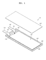
- FIG. 1 is an exploded perspective view illustrating a flexible secondary battery 10 according to an embodiment of the present invention.
- FIG. 2 is a plan view illustrating an electrode assembly 100 of the flexible secondary battery 10 of FIG. 1 .
- FIG. 3 is a cross-sectional view taken along line I-I of FIG. 2 .
- FIG. 4 is a perspective view illustrating a gasket 200B that is a modification of a gasket 200 of the flexible secondary battery 10 of FIG. 1 .
- FIG. 5 is a perspective view illustrating a gasket 200C that is another modification of the gasket 200 of the flexible secondary battery 10 of FIG. 1 .
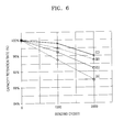
- FIG. 6 is a graph illustrating a capacity retention rate after repeated bending cycles of the flexible secondary battery 10 of FIG. 1 .
- the flexible secondary battery 10 may include the electrode assembly 100, the gasket 200 that surrounds edges of the electrode assembly 100, a first sealing sheet 310 that is attached to a first surface of the gasket 200, and a second sealing sheet 320 that is attached to a second surface of the gasket 200 that is opposite to the first surface.
- the electrode assembly 100 may include a first electrode layer 110, a second electrode layer 120, and a separator 130 that is disposed between the first electrode layer 110 and the second electrode layer 120.
- the electrode assembly 100 may have a structure in which a plurality of the first electrode layers 110, a plurality of the separators 130, and a plurality of the second electrode layers 120 are repeatedly stacked.
- the first electrode layer 110 may be any one of a positive film and a negative film.
- the second electrode layer 120 may be a negative film, and in contrast, when the first electrode layer 110 is a negative film, the second electrode layer 120 may be a positive film.
- the first electrode layer 110 may include a first metal current collector 112, a first active material unit 114 that is formed by coating a surface of the first metal current collector 112 with a first active material, and a first non-coated portion 116 on which the first active material is not coated.
- the second electrode layer 120 may include a second metal current collector 122, a second active material unit 124 that is formed by coating a surface of the second metal current collector 122 with a second active material, and a second non-coated portion 126 on which the second active material is not coated.
- the first metal current collector 112 may be a positive current collector and the first active material unit 114 may be a positive active material unit.
- the second metal current collector 122 may be a negative current collector and the second active material unit 124 may be a negative active material unit.
- the positive current collector may be formed of aluminum, stainless steel, titanium, silver, or a combination thereof.
- the positive active material unit may include a positive active material, a binder, and a conductive material.
- the positive active material may be a material that may reversibly occlude and release lithium ions.
- the positive active material may include at least one selected from the group consisting of a lithium transition metal oxide such as lithium cobalt oxide, lithium nickel oxide, lithium nickel cobalt oxide, lithium nickel cobalt aluminum oxide, lithium nickel cobalt manganese oxide, lithium manganese oxide, or lithium iron phosphate, nickel sulfide, copper sulfide, sulfur, iron oxide, and vanadium oxide.
- the binder may include at least one selected from the group consisting of a polyvinylidene fluoride-based binder such as polyvinylidene fluoride, vinylidene fluoride/hexafluoropropylene copolymer, or vinylidene fluoride/tetrafluoroethylene copolymer, a carboxymethyl cellulose-based binder such as sodium-carboxymethyl cellulose or lithium-carboxymethyl cellulose, an acrylate-based binder such as polyacrylic acid, lithium-polyacrylic acid, acryl, polyacrylonitrile, polymethyl methacrylate, or polybutyl acrylate, polyamideimide, polytetrafluoroethylene, polyethylene oxide, polypyrrole, lithium-nafion, and a styrene butadiene rubber-based polymer.
- a polyvinylidene fluoride-based binder such as polyvinylidene fluoride, vinylidene fluoride/hexa
- the conductive material may include at least one selected from the group consisting of a carbon-based conductive material such as carbon black, carbon fiber, or graphite, a conductive fiber such as a metal fiber, metal powder such as carbon fluoride powder, aluminum powder, or nickel powder, a conductive whisker such as zinc oxide or potassium titanate, a conductive metal oxide such as titanium oxide, and a conductive polymer such as a polyphenylene derivative.
- a carbon-based conductive material such as carbon black, carbon fiber, or graphite
- a conductive fiber such as a metal fiber
- metal powder such as carbon fluoride powder, aluminum powder, or nickel powder
- a conductive whisker such as zinc oxide or potassium titanate
- a conductive metal oxide such as titanium oxide
- a conductive polymer such as a polyphenylene derivative
- the negative current collector may include at least one metal selected from the group consisting of copper, stainless steel, nickel, and titanium.
- the negative active material unit may include a negative active material, a binder, and a conductive material.
- the negative active material may include a material that may become an alloy with lithium, or may reversibly occlude or release lithium.
- the negative active material may include at least one selected from the group consisting of a metal, a carbon-based material, a metal oxide, and a lithium metal nitride.
- the metal may include at least one selected from the group consisting of lithium, silicon, magnesium, calcium, aluminum, germanium, tin, lead, arsenic, antimony, bismuth, silver, gold, zinc, cadmium, mercury, copper, iron, nickel, cobalt, and indium.
- the carbon-based material may include at least one selected from the group consisting of graphite, graphite carbon fiber, coke, mesocarbon microbeads (MCMB), polyacene, pitch-based carbon fiber, and hard carbon.
- the metal oxide may include at least one selected from the group consisting of lithium titanium oxide, titanium oxide, molybdenum oxide, niobium oxide, iron oxide, tungsten oxide, tin oxide, amorphous tin mixed oxide, silicon monoxide, cobalt oxide, and nickel oxide.
- the binder and the conductive material may be the same as those included in the positive active material unit.
- the separator 130 may be formed by, but is not limited to, coating at least one material selected from the group consisting of polyethylene (PE), polystyrene (PS), polypropylene (PP), and a co-polymer of PE and PP with polyvinylidene fluoride cohexafluoropropylene (PVDF-HFP) co-polymer.
- PE polyethylene
- PS polystyrene
- PP polypropylene
- PVDF-HFP polyvinylidene fluoride cohexafluoropropylene
- a first electrode tab 118 and a second electrode tab 128 are attached to the electrode assembly 110.
- the first electrode tab 118 and the second electrode tab 128 may be respectively attached by using welding or the like to a plurality of the first non-coated portions 116 and a plurality of the second non-coated portions 126 that are stacked.
- the electrode assembly 100 may further include a fixing member 140 that fixes one end portion of each of the first electrode layer 110, the separator 130, and the second electrode layer 120.
- the fixing member 140 that is disposed between the first non-coated portion 116 and the separator 130 and between the separator 130 and the second non-coated portion 126 may be, but is not limited to, an adhesive or a tape to which an adhesive is applied.
- the fixing member 140 fixes only the one end portion of each of the first electrode layer 110, the separator 130, and the second electrode layer 120. Accordingly, in an area where the fixing member 140 is not formed, the electrode assembly 100 may bend due to slippage between the first electrode 110, the separator 130, and the second electrode layer 120, and relative positions of the first electrode layer 110, the separator 130, and the second electrode layer 120 may be maintained due to the fixing member 140 even when the electrode assembly 100 is repeatedly bent.
- the fixing member 140 may be formed on the same side of the electrode assembly 100 as the first electrode tab 118 and the second electrode tab 128 in a longitudinal direction of the electrode assembly 100.
- each of the first electrode 110, the separator 130, and the second electrode layer 120 on which the fixing member 140 is not formed undergoes a greater displacement than the one end portion of each of the first electrode layer 110, the separator 130, and the second electrode layer 120 on which the fixing member 140 is formed when the electrode assembly 100 is bent. Since the first electrode tab 118 may be adhered to the plurality of first non-coated portions 116 and the second electrode tab 128 may be adhered to the plurality of second non-coated portions 126, the first electrode tab 118 and the second electrode tab 128 may be actually respectively used as fixing units for fixing the first electrode layers 110 and the second electrode layers 120.
- the fixing member 140 is formed on the opposite side of the electrode assembly 110 to the first electrode tab 118 and the second electrode tab 128 in the longitudinal direction of the electrode assembly 100, when the electrode assembly 100 is bent, the first electrode layer 110 and/or the second electrode layer 120 may bend between the first and second electrode taps 118 and 128 and the fixing member 140 and a part of the fixing member 140 may be destroyed, thereby making it difficult to maintain alignment between the first electrode layer 110, the separator 130, and the second electrode layer 120.
- a protective layer may be formed on an outermost surface of the electrode assembly 100.
- the protective layer may prevent the first electrode layer 110, the separator 130, or the second electrode layer 120 from wrinkling when the electrode assembly 100 is bent. That is, when the electrode assembly 100 is bent, the first electrode layer 110, the separator 130, and the second electrode layer 120 tend to wrinkle in order to reduce a compressive stress.
- the protective layer may prevent a greater deformation by pressing down the first electrode layer 110, the separator 130, or the second electrode 120, and thus, may reduce a stress applied to the first electrode 110, the separator 130, or the second electrode layer 120.
- a bending stiffness of the protective layer may be greater than an average bending stiffness of the first electrode layer 110, the separator 130, and the second electrode layer 120.
- a bending stiffness of the protective layer may be about 1.5 times greater than an average bending stiffness of the first electrode layer 110, the separator 130, and the second electrode layer 120.
- the protective layer may be formed of a material that has not only a predetermined stiffness but also a predetermined flexibility in order not to affect the bending of the electrode assembly 100.
- the protective layer may be formed as, but is not limited to, a polymer film, a film including a laminated polymer film layer, a metal foil, or a composite film including carbon.
- the protective layer may have a thickness ranging from about 15 micrometers to about 1 millimeter, and a tensile modulus of elasticity of the protective layer may range from about 0.5 GPa to about 300 GPa.
- the gasket 200 may surround the edges of the electrode assembly 100, may have an internal space whose central portion is open and in which the electrode assembly 100 may be located, and may be formed of a flexible material. Accordingly, the gasket 200 may bend along with the electrode assembly 100 when the electrode assembly 100 bends, and thus may uniformly distribute a stress that is generated when the flexible secondary battery 10 is bent, thereby preventing damage to the electrode assembly 100 due to concentration of the stress.
- the first sealing sheet 310 may be attached to the first surface of the gasket 200 and the second sealing sheet 320 may be attached to the second surface of the gasket 200 opposite the first surface.
- the first sealing sheet 310 and the second sealing sheet 320 may seal the electrode assembly 100 along with the gasket 200.
- Each of the first sealing sheet 310 and the second sealing sheet 320 may include a first insulating layer, a metal layer, and a second insulating layer that are sequentially stacked.
- Each of the first insulating layer and the second insulating layer may be formed of PP, polyethyleneterephthalate (PET), or nylon, and the metal layer may be formed of, but is not limited to, aluminum, steel, or stainless steel.
- each of the first sealing sheet 310 and the second sealing sheet 320 may have a three-layer structure including the first insulating layer formed of PP, the metal layer formed of aluminum, and the second insulating layer formed of PET, wherein the first insulating layer of each of the first sealing sheet 310 and the second sealing sheet 320 is disposed to contact the gasket 200.
- the first insulating layer may be attached by using thermal bonding to the gasket 200.
- the gasket 200 may be formed such that a difference between a melting point of a material of the gasket 200 and a melting point of a material of the first insulating layer is equal to or less than 50°C.
- the gasket 200 may be formed of the same material as that of the first insulating layer.
- the gasket 200 may include an uneven pattern 202 that is formed on at least an area (hereinafter, referred to as a bendable area) of the gasket 200 that may be bent when the flexible secondary battery 10 is bent.
- the uneven pattern 202 may be formed such that ridges and furrows are continuously and repeatedly arranged in the longitudinal direction of the electrode assembly 100.
- the uneven pattern 202 may have, but is not limited to, a wave shape.
- the uneven pattern 202 may be formed on at least one selected from the first surface to which the first sealing sheet 310 is attached, the second surface to which the second sealing sheet 320 is attached, and one pair of side surfaces that connect the first surface and the second surface. Accordingly, at least one selected from a thickness and a width of the gasket 200 in a portion where the uneven pattern 202 is formed may vary according to the longitudinal direction of the electrode assembly 100.
- FIG. 1 illustrates that the uneven pattern 202 is regularly formed on the first surface and the second surface of the gasket 200.
- a thickness of the gasket 200 may continuously vary according to the longitudinal direction of the electrode assembly 100, the flexible secondary battery 10 may be easily bent, and a stress that is generated when the flexible secondary battery 10 is bent may be uniformly distributed.
- the first sealing sheet 310 and the second sealing sheet 320 may be easily deformed when the flexible secondary battery 10 is bent, thereby improving the reliability of the flexible secondary battery 10.
- FIG. 4 is a perspective view illustrating the gasket 200B that is a modification of the gasket 200 of FIG. 1 .
- the uneven pattern 202 is formed to have partially different pitches. That is, the uneven pattern 202 that is formed on a central portion A1 in the bendable area of the gasket 200B may be denser than the uneven pattern 202 that is formed on an outer portion A2. Since the uneven pattern 202 is denser in the central portion A1 where the gasket 200B undergoes greater deformation than in the outer portion A2, a stress may be effectively prevented from concentrating on the central portion A1.
- FIG. 5 is a perspective view illustrating the gasket 200C that is another modification of the gasket 200 of FIG. 1 .
- the gasket 200C of FIG. 5 includes the uneven pattern 202 (hereinafter, referred to as a first uneven pattern) that is formed on the first surface and the second surface and a second uneven pattern 204 that is formed on an inner side surface from among the one pair of side surfaces that connect the first surface and the second surface. That is, the gasket 200C of FIG. 5 further includes the second uneven pattern 204 when compared to the gasket 200 of FIG. 1 , and a thickness and a width of the gasket 200C may vary in the longitudinal direction of the electrode assembly 100. As such, when the second uneven pattern 204 is further provided, the gasket 200C may be more easily deformed, thereby more effectively distributing a stress that is generated when the flexible secondary battery 10 is bent.
- the gasket 200C may include only the second uneven pattern 204. That is, the first surface and the second surface of the gasket 200C may be flat, and thus a bonding force and a sealing force between the gasket 200C and the first and second sealing sheets 310 and 320 may be increased. Also, like in FIG. 4 , the gasket 200C may be formed such that the first uneven pattern 202 and/or the second uneven pattern 204 are denser in a portion where the gasket 200C of FIG. 5 undergoes greater deformation.
- the gasket 200 may be formed to have a thickness ranging from about 80% to about 120% of a thickness of the electrode assembly 100, thereby preventing a bent portion from being formed in the first sealing sheet 310 and the second sealing sheet 320.
- a thickness of the gasket 200 varies according to the longitudinal direction of the electrode assembly 100, the thickness of the gasket 200 is referred to as an average thickness.
- a stress may concentrate on the bent portion that is formed in the first sealing sheet 310 and the second sealing sheet 320 when the flexible secondary battery 10 is bent, thereby resulting in damage (e.g., tear) to the first sealing sheet 310 and the second sealing sheet 320.
- the gasket 200 is formed to have a thickness ranging from about 80% to about 120% of that of the electrode assembly 100, the bent portion may be prevented from being formed in the first sealing sheet 310 and the second sealing sheet 320 when the flexible secondary battery 10 is bent and a stress may be uniformly distributed, not concentrating on a specific portion of the first sealing sheet 310 and the second sealing sheet 320, thereby improving the stability of the flexible secondary battery 10.
- the second sealing sheet 320 is attached to the second surface of the gasket 200.
- the second sealing sheet 320 may be attached to the second surface of the gasket 200 such that the first insulating layer faces the gasket 200 and then the gasket 200 and the first insulating layer are thermally bonded to each other.
- the electrode assembly 100 is disposed in the internal space of the gasket 200, and then the first sealing sheet 310 is attached to the first surface of the gasket 200.
- a method of attaching the first sealing sheet 310 is the same as a method of attaching the second sealing sheet 320.
- the first electrode tab 118 and the second electrode tab 128 of the electrode assembly 100 may be pulled to the outside through between the gasket 200 and the first sealing sheet 310, and in order to increase a bonding force between the gasket 200 and the second sealing sheet 310 and to prevent a shortcircuit between the first electrode tab 118 and the second electrode tab 128, insulating films 150 may be attached to outer surfaces of the first electrode tab 118 and the second electrode tab 128 that overlap with the gasket 200.
- the present embodiment is not limited thereto and the first sealing sheet 310 may be first attached, or the electrode assembly 100 may be disposed in the gasket 200 and then the first sealing sheet 310 and the second sealing sheet 320 may be simultaneously or sequentially attached to the gasket 200.
- a drawing work depth increases to correspond to the thickness of the electrode assembly 100, thereby increasing the risk of a crack in the pouch.
- the flexible secondary battery 10 of the present embodiment since a thickness of the gasket 200 is freely determined according to a thickness of the electrode assembly 100, the flexible secondary battery 10 having a large capacity may be easily manufactured.
- the gasket 200 is formed of a flexible material, bends along with the electrode assembly 100, and includes the uneven pattern 202 that is formed on the bendable area of the gasket 200, a stress that is generated when the flexible secondary battery 10 is bent may be uniformly distributed, thereby maintaining the stability and reliability of the flexible secondary battery 10 even when the flexible secondary battery 10 is repeatedly bent.
- Table 1 shows a result obtained after flexible secondary batteries of Comparative Example 1 and Comparative Example 2 is repeatedly bent 1000 times and 2000 times to have a curvature radius of 25 mm and then capacity retention rates of the flexible secondary batteries of Comparative Example 1 and Comparative Example 2 are compared with each other.
- Comparative Example 1 corresponds to a case where a receiving portion in which the flexible secondary battery is received is formed in a pouch by using a drawing work and then the pouch outside the receiving portion is sealed by using thermal bonding.
- Comparative Example 2 corresponds to a case where the gasket 200 in the flexible secondary battery 10 of FIG. 1 includes no uneven pattern.
- a capacity retention rate after 1000 bending cycles is reduced to 75.4% and is greatly reduced to 23.6% after 2000 bending cycles.
- a capacity retention rate is equal to or greater than 90% even after 2000 bending cycles. This is because the gasket 200 bends along with the flexible secondary battery 10 when the flexible secondary battery 10 is bent and thus a stress may be uniformly distributed, thereby preventing damage to the electrode assembly 100.
- FIG. 6 is a graph illustrating a result obtained after flexible secondary batteries repeatedly bend 1000 times and 2000 times to have a curvature radius of 25 mm and then capacity retention rates of the flexible secondary batteries are compared with one another.
- case A corresponds to the same case as Comparative Example 2 of Table 1
- cases B, C, and D correspond to embodiments of the present invention.
- case A corresponds to a case where the gasket 200 in the flexible secondary battery 10 of FIG. 1 includes no uneven pattern, like in Comparative Example 2 of Table 1.
- case B corresponds to a case where the gasket 200 in the flexible secondary battery 10 of FIG. 1 includes the uneven pattern 202 that is formed on the first surface and the second surface.
- Case C corresponds to a case where the flexible secondary battery 10 includes the gasket 200C of FIG. 5 .
- case D corresponds to a case where the flexible secondary battery 10 includes the gasket 200C including only the second uneven pattern 204 of FIG. 5 .
- cases B, C, and D have a lower capacity reduction rate than case A. That is, when the gasket 200 is formed such that at least one selected from a thickness and a width varies according to the longitudinal direction of the electrode assembly 100, a stress that is generated when the flexible secondary battery 10 repeatedly bends may be more uniformly distributed, thereby further improving the reliability of the flexible secondary battery 10.
- FIG. 7 is an exploded perspective view illustrating a flexible secondary battery 20 that is a modification of the flexible secondary battery 10 of FIG. 1 .
- FIG. 8 is a plan view illustrating a gasket 210 of the flexible secondary battery 20 of FIG. 7 .
- the flexible secondary battery 20 may include the electrode assembly 100, the gasket 210 that surrounds an edge of the electrode assembly 100, the first sealing sheet 310 that is attached to a first surface of the gasket 210, and the second sealing sheet 320 that is attached to a second surface of the gasket 210 that is opposite to the first surface.
- the electrode assembly 100, the first sealing sheet 310, and the second sealing sheet 320 are the same as those of FIGS. 1 through 3 , and thus a repeated explanation thereof will not be given.
- the gasket 210 may surround the edge of the electrode assembly 100 and may be formed of a flexible material. Accordingly, the gasket 210 bends along with the electrode assembly 100 when the flexible secondary battery 20 is bent, and thus may uniformly distribute a stress, thereby effectively preventing damage to the electrode assembly 100.
- the gasket 210 may include a first lead electrode 212 and a second lead electrode 214 that pass through one side of the gasket 210.
- the first lead electrode 212 and the second lead electrode 214 may be integrally formed with the gasket 210 by using insert molding.
- the first lead electrode 212 may be adhered to the first electrode tab 118 in an internal space of the gasket 210, and the second lead electrode 214 may be adhered to the second electrode tab 128 in the internal space of the gasket 210.
- the first electrode tab 118 may be adhered to the first non-coated portion 116 and the second electrode tab 128 may be adhered to the second non-coated portion 126.
- first electrode tab 118 and the second electrode tab 128 are respectively connected to the first lead electrode 212 and the second lead electrode 214, the first electrode tab 118 and the second electrode tab 128 are connected to the outside without bending, thereby preventing damage to the first electrode tab 118 and the second electrode tab 128. Also, since the first electrode tab 118 and the second electrode tab 128 are not disposed between the gasket 210 and the first sealing sheet 310 or the second sealing sheet 320, a bonding force between the gasket 210 and the first sealing sheet 310 or the second sealing sheet 320 may be increased.
- a method of manufacturing the flexible secondary battery 20 is basically the same as the method of manufacturing the flexible secondary battery 10 described with reference to FIGS. 1 through 3 .
- the first electrode tab 118 and the second electrode tab 128 may be respectively attached to the first lead electrode 212 and the second lead electrode 214 by using welding or the like.
- the stability and reliability of a flexible secondary battery may be maintained even after the flexible secondary battery is repeatedly bent.
Landscapes
- Chemical & Material Sciences (AREA)
- Chemical Kinetics & Catalysis (AREA)
- Electrochemistry (AREA)
- General Chemical & Material Sciences (AREA)
- Inorganic Chemistry (AREA)
- Engineering & Computer Science (AREA)
- Manufacturing & Machinery (AREA)
- Materials Engineering (AREA)
- Sealing Battery Cases Or Jackets (AREA)
- Secondary Cells (AREA)
- Connection Of Batteries Or Terminals (AREA)
Abstract
Description
- One or more embodiments of the present invention relate to a flexible secondary battery.
- As the electronic technology has developed, the market for various mobile electronic devices such as smart phones, smart pads, e-book readers, flexible tablet computers, or wearable medical devices as well as mobile phones, game players, portable multimedia players (PMPs), or MPEG audio layer-3 (MP3) players has greatly grown.
- As the market for mobile electronic devices has grown, the demand for batteries suitable for the mobile electronic devices has also increased. As the demand for flexible mobile electronic devices with improved utility, mobility, storage, and impact resistance has increased, the demand for flexible batteries to be used in the flexible mobile electronic devices has also increased.
- The present invention sets-out to provide aflexible secondary battery of which stability may be maintained even after the flexible secondary battery is repeatedly bent.
- Additional aspects will be set forth in part in the description which follows and, in part, will be apparent from the description, or may be learned by practice of the presented embodiments.
- According to one or more embodiments of the present invention, a flexible secondary battery includes: an electrode assembly that includes a first electrode layer, a second electrode layer, and a separator that is disposed between the first electrode layer and the second electrode layer; a gasket that is flexible and surrounds edges of the electrode assembly; a first sealing sheet that is attached to a first surface of the gasket; and a second sealing sheet that is attached to a second surface of the gasket opposite the first surface, wherein an uneven pattern is formed on a bendable area of the gasket.
- The uneven pattern may be formed on at least one selected from the first surface, the second surface, and one pair of side surfaces that connect the first surface and the second surface.
- At least one selected from a thickness and a width of the gasket may vary in the bendable area in a longitudinal direction of the electrode assembly.
- An average thickness of the gasket may range from about 80% to about 120% of a thickness of the electrode assembly.
- The uneven pattern may be formed to be denser on a central portion of the bendable area than on an outer portion of the bendable area.
- The uneven pattern may have a wave shape.
- Each of the first sealing sheet and the second sealing sheet may include a first insulating layer, a metal layer, and a second insulating layer, wherein the first insulating layer contacts the gasket and the gasket and the first insulating layer are formed of same material.
- The first electrode layer may include a first active material unit, the first active material unit being formed by coating a first metal current collector with a first active material, and a first non-coated portion on which the first active material is not coated and to which a first electrode tab is attached, and the second electrode layer includes a second active material unit, the second active material unit being formed by coating a second metal current collector with a second active material, and a second non-coated portion on which the second active material is not coated and to which a second electrode tab is attached.
- The first electrode tab and the second electrode tab may be pulled to the outside through between the gasket and the first sealing sheet or through between the gasket and the second sealing sheet.
- The gasket may include a first lead electrode and a second lead electrode that pass through one side of the gasket, wherein the first lead electrode is adhered to the first electrode tab and the second lead electrode is adhered to the second electrode tab in an internal space of the gasket.
- The electrode assembly may further include a fixing member that fixes one end portion of each of the first electrode layer, the separator, and the second electrode layer.
- At least some of the above and other features of the invention are set-out in the claims.
- These and/or other aspects of the invention will become apparent and more readily appreciated from the following description of embodiments thereof, taken in conjunction with the accompanying drawings in which:
-
FIG. 1 is an exploded perspective view illustrating a flexible secondary battery according to an embodiment of the present invention; -
FIG. 2 is a plan view illustrating an electrode assembly of the flexible secondary battery ofFIG. 1 ; -
FIG. 3 is a cross-sectional view taken along line I-I ofFIG. 2 ; -
FIG. 4 is a perspective view illustrating a gasket that is a modification of a gasket of the flexible secondary battery ofFIG. 1 ; -
FIG. 5 is a perspective view illustrating a gasket that is another modification of the gasket of the flexible secondary battery ofFIG. 1 ; -
FIG. 6 is a graph illustrating a capacity retention rate after repeated bending cycles of the flexible secondary battery ofFIG. 1 ; -
FIG. 7 is an exploded perspective view illustrating a flexible secondary battery that is a modification of the flexible secondary battery ofFIG. 1 ; and -
FIG. 8 is a plan view illustrating a gasket of the flexible secondary battery ofFIG. 7 . - The present invention may include various embodiments and modifications, and embodiments thereof will be illustrated in the drawings and will be described herein in detail. The effects and features of the present invention and the accompanying methods thereof will become apparent from the following description of the embodiments, taken in conjunction with the accompanying drawings. However, the present invention is not limited to the embodiments described below, and may be embodied in various modes.
- Reference will now be made in detail to embodiments, examples of which are illustrated in the accompanying drawings. In the drawings, the same elements are denoted by the same reference numerals, and a repeated explanation thereof will not be given.
- It will be understood that although the terms "first", "second", etc. may be used herein to describe various elements, these elements should not be limited by these terms. These elements are only used to distinguish one element from another.
- As used herein, the singular forms "a," "an" and "the" are intended to include the plural forms as well, unless the context clearly indicates otherwise.
- It will be further understood that the terms "comprises" and/or "comprising" used herein specify the presence of stated features or components, but do not preclude the presence or addition of one or more other features or components.
- It will be understood that when an element is referred to as being "formed on," another element, it can be directly or indirectly formed on the other element. That is, for example, intervening elements may be present.
- Sizes of elements may be exaggerated for convenience of explanation. In other words, since sizes and thicknesses of elements in the drawings are arbitrarily illustrated for convenience of explanation, the following embodiments are not limited thereto.
- As used herein, the term "and/or" includes any and all combinations of one or more of the associated listed items. Expressions such as "at least one of," when preceding a list of elements, modify the entire list of elements and do not modify the individual elements of the list.
-
FIG. 1 is an exploded perspective view illustrating a flexiblesecondary battery 10 according to an embodiment of the present invention.FIG. 2 is a plan view illustrating anelectrode assembly 100 of the flexiblesecondary battery 10 ofFIG. 1 .FIG. 3 is a cross-sectional view taken along line I-I ofFIG. 2 .FIG. 4 is a perspective view illustrating agasket 200B that is a modification of agasket 200 of the flexiblesecondary battery 10 ofFIG. 1 .FIG. 5 is a perspective view illustrating agasket 200C that is another modification of thegasket 200 of the flexiblesecondary battery 10 ofFIG. 1 .FIG. 6 is a graph illustrating a capacity retention rate after repeated bending cycles of the flexiblesecondary battery 10 ofFIG. 1 . - Referring to
FIGS. 1 through 3 , the flexiblesecondary battery 10 may include theelectrode assembly 100, thegasket 200 that surrounds edges of theelectrode assembly 100, afirst sealing sheet 310 that is attached to a first surface of thegasket 200, and asecond sealing sheet 320 that is attached to a second surface of thegasket 200 that is opposite to the first surface. - The
electrode assembly 100 may include afirst electrode layer 110, asecond electrode layer 120, and aseparator 130 that is disposed between thefirst electrode layer 110 and thesecond electrode layer 120. For example, theelectrode assembly 100 may have a structure in which a plurality of thefirst electrode layers 110, a plurality of theseparators 130, and a plurality of thesecond electrode layers 120 are repeatedly stacked. - The
first electrode layer 110 may be any one of a positive film and a negative film. When thefirst electrode layer 110 is a positive film, thesecond electrode layer 120 may be a negative film, and in contrast, when thefirst electrode layer 110 is a negative film, thesecond electrode layer 120 may be a positive film. - The
first electrode layer 110 may include a first metalcurrent collector 112, a firstactive material unit 114 that is formed by coating a surface of the first metalcurrent collector 112 with a first active material, and a first non-coatedportion 116 on which the first active material is not coated. Likewise, thesecond electrode layer 120 may include a second metal current collector 122, a secondactive material unit 124 that is formed by coating a surface of the second metal current collector 122 with a second active material, and a second non-coatedportion 126 on which the second active material is not coated. - When the
first electrode layer 110 is a positive film, the first metalcurrent collector 112 may be a positive current collector and the firstactive material unit 114 may be a positive active material unit. When thesecond electrode layer 120 is a negative film, the second metal current collector 122 may be a negative current collector and the secondactive material unit 124 may be a negative active material unit. - The positive current collector may be formed of aluminum, stainless steel, titanium, silver, or a combination thereof. The positive active material unit may include a positive active material, a binder, and a conductive material.
- The positive active material may be a material that may reversibly occlude and release lithium ions. For example, the positive active material may include at least one selected from the group consisting of a lithium transition metal oxide such as lithium cobalt oxide, lithium nickel oxide, lithium nickel cobalt oxide, lithium nickel cobalt aluminum oxide, lithium nickel cobalt manganese oxide, lithium manganese oxide, or lithium iron phosphate, nickel sulfide, copper sulfide, sulfur, iron oxide, and vanadium oxide.
- The binder may include at least one selected from the group consisting of a polyvinylidene fluoride-based binder such as polyvinylidene fluoride, vinylidene fluoride/hexafluoropropylene copolymer, or vinylidene fluoride/tetrafluoroethylene copolymer, a carboxymethyl cellulose-based binder such as sodium-carboxymethyl cellulose or lithium-carboxymethyl cellulose, an acrylate-based binder such as polyacrylic acid, lithium-polyacrylic acid, acryl, polyacrylonitrile, polymethyl methacrylate, or polybutyl acrylate, polyamideimide, polytetrafluoroethylene, polyethylene oxide, polypyrrole, lithium-nafion, and a styrene butadiene rubber-based polymer.
- The conductive material may include at least one selected from the group consisting of a carbon-based conductive material such as carbon black, carbon fiber, or graphite, a conductive fiber such as a metal fiber, metal powder such as carbon fluoride powder, aluminum powder, or nickel powder, a conductive whisker such as zinc oxide or potassium titanate, a conductive metal oxide such as titanium oxide, and a conductive polymer such as a polyphenylene derivative.
- The negative current collector may include at least one metal selected from the group consisting of copper, stainless steel, nickel, and titanium. The negative active material unit may include a negative active material, a binder, and a conductive material.
- The negative active material may include a material that may become an alloy with lithium, or may reversibly occlude or release lithium. For example, the negative active material may include at least one selected from the group consisting of a metal, a carbon-based material, a metal oxide, and a lithium metal nitride.
- The metal may include at least one selected from the group consisting of lithium, silicon, magnesium, calcium, aluminum, germanium, tin, lead, arsenic, antimony, bismuth, silver, gold, zinc, cadmium, mercury, copper, iron, nickel, cobalt, and indium.
- The carbon-based material may include at least one selected from the group consisting of graphite, graphite carbon fiber, coke, mesocarbon microbeads (MCMB), polyacene, pitch-based carbon fiber, and hard carbon.
- The metal oxide may include at least one selected from the group consisting of lithium titanium oxide, titanium oxide, molybdenum oxide, niobium oxide, iron oxide, tungsten oxide, tin oxide, amorphous tin mixed oxide, silicon monoxide, cobalt oxide, and nickel oxide.
- The binder and the conductive material may be the same as those included in the positive active material unit.
- The
separator 130 may be formed by, but is not limited to, coating at least one material selected from the group consisting of polyethylene (PE), polystyrene (PS), polypropylene (PP), and a co-polymer of PE and PP with polyvinylidene fluoride cohexafluoropropylene (PVDF-HFP) co-polymer. - A
first electrode tab 118 and asecond electrode tab 128 are attached to theelectrode assembly 110. In detail, thefirst electrode tab 118 and thesecond electrode tab 128 may be respectively attached by using welding or the like to a plurality of the firstnon-coated portions 116 and a plurality of the secondnon-coated portions 126 that are stacked. - The
electrode assembly 100 may further include a fixingmember 140 that fixes one end portion of each of thefirst electrode layer 110, theseparator 130, and thesecond electrode layer 120. The fixingmember 140 that is disposed between the firstnon-coated portion 116 and theseparator 130 and between theseparator 130 and the secondnon-coated portion 126 may be, but is not limited to, an adhesive or a tape to which an adhesive is applied. - The fixing
member 140 fixes only the one end portion of each of thefirst electrode layer 110, theseparator 130, and thesecond electrode layer 120. Accordingly, in an area where the fixingmember 140 is not formed, theelectrode assembly 100 may bend due to slippage between thefirst electrode 110, theseparator 130, and thesecond electrode layer 120, and relative positions of thefirst electrode layer 110, theseparator 130, and thesecond electrode layer 120 may be maintained due to the fixingmember 140 even when theelectrode assembly 100 is repeatedly bent. - The fixing
member 140 may be formed on the same side of theelectrode assembly 100 as thefirst electrode tab 118 and thesecond electrode tab 128 in a longitudinal direction of theelectrode assembly 100. - The other end portion of each of the
first electrode 110, theseparator 130, and thesecond electrode layer 120 on which the fixingmember 140 is not formed undergoes a greater displacement than the one end portion of each of thefirst electrode layer 110, theseparator 130, and thesecond electrode layer 120 on which the fixingmember 140 is formed when theelectrode assembly 100 is bent. Since thefirst electrode tab 118 may be adhered to the plurality of firstnon-coated portions 116 and thesecond electrode tab 128 may be adhered to the plurality of secondnon-coated portions 126, thefirst electrode tab 118 and thesecond electrode tab 128 may be actually respectively used as fixing units for fixing the first electrode layers 110 and the second electrode layers 120. - Accordingly, assuming that the fixing
member 140 is formed on the opposite side of theelectrode assembly 110 to thefirst electrode tab 118 and thesecond electrode tab 128 in the longitudinal direction of theelectrode assembly 100, when theelectrode assembly 100 is bent, thefirst electrode layer 110 and/or thesecond electrode layer 120 may bend between the first and second electrode taps 118 and 128 and the fixingmember 140 and a part of the fixingmember 140 may be destroyed, thereby making it difficult to maintain alignment between thefirst electrode layer 110, theseparator 130, and thesecond electrode layer 120. - A protective layer (not shown) may be formed on an outermost surface of the
electrode assembly 100. The protective layer may prevent thefirst electrode layer 110, theseparator 130, or thesecond electrode layer 120 from wrinkling when theelectrode assembly 100 is bent. That is, when theelectrode assembly 100 is bent, thefirst electrode layer 110, theseparator 130, and thesecond electrode layer 120 tend to wrinkle in order to reduce a compressive stress. When thefirst electrode layer 110, theseparator 130, or thesecond electrode layer 120 is about to undergo a deformation with a small radius of curvature, such as a wrinkle, the protective layer may prevent a greater deformation by pressing down thefirst electrode layer 110, theseparator 130, or thesecond electrode 120, and thus, may reduce a stress applied to thefirst electrode 110, theseparator 130, or thesecond electrode layer 120. - As such, in order for the protective layer to prevent the
first electrode layer 110, theseparator 130, or thesecond electrode layer 120 from wrinkling, a bending stiffness of the protective layer may be greater than an average bending stiffness of thefirst electrode layer 110, theseparator 130, and thesecond electrode layer 120. For example, a bending stiffness of the protective layer may be about 1.5 times greater than an average bending stiffness of thefirst electrode layer 110, theseparator 130, and thesecond electrode layer 120. - Also, the protective layer may be formed of a material that has not only a predetermined stiffness but also a predetermined flexibility in order not to affect the bending of the
electrode assembly 100. For example, the protective layer may be formed as, but is not limited to, a polymer film, a film including a laminated polymer film layer, a metal foil, or a composite film including carbon. For example, the protective layer may have a thickness ranging from about 15 micrometers to about 1 millimeter, and a tensile modulus of elasticity of the protective layer may range from about 0.5 GPa to about 300 GPa. - The
gasket 200 may surround the edges of theelectrode assembly 100, may have an internal space whose central portion is open and in which theelectrode assembly 100 may be located, and may be formed of a flexible material. Accordingly, thegasket 200 may bend along with theelectrode assembly 100 when theelectrode assembly 100 bends, and thus may uniformly distribute a stress that is generated when the flexiblesecondary battery 10 is bent, thereby preventing damage to theelectrode assembly 100 due to concentration of the stress. - The
first sealing sheet 310 may be attached to the first surface of thegasket 200 and thesecond sealing sheet 320 may be attached to the second surface of thegasket 200 opposite the first surface. Thefirst sealing sheet 310 and thesecond sealing sheet 320 may seal theelectrode assembly 100 along with thegasket 200. - Each of the
first sealing sheet 310 and thesecond sealing sheet 320 may include a first insulating layer, a metal layer, and a second insulating layer that are sequentially stacked. Each of the first insulating layer and the second insulating layer may be formed of PP, polyethyleneterephthalate (PET), or nylon, and the metal layer may be formed of, but is not limited to, aluminum, steel, or stainless steel. - For example, each of the
first sealing sheet 310 and thesecond sealing sheet 320 may have a three-layer structure including the first insulating layer formed of PP, the metal layer formed of aluminum, and the second insulating layer formed of PET, wherein the first insulating layer of each of thefirst sealing sheet 310 and thesecond sealing sheet 320 is disposed to contact thegasket 200. - The first insulating layer may be attached by using thermal bonding to the
gasket 200. In this case, in order to improve a thermal bonding efficiency and increase a bonding force between the first insulating layer and thegasket 200, thegasket 200 may be formed such that a difference between a melting point of a material of thegasket 200 and a melting point of a material of the first insulating layer is equal to or less than 50°C. For example, thegasket 200 may be formed of the same material as that of the first insulating layer. - The
gasket 200 may include anuneven pattern 202 that is formed on at least an area (hereinafter, referred to as a bendable area) of thegasket 200 that may be bent when the flexiblesecondary battery 10 is bent. Theuneven pattern 202 may be formed such that ridges and furrows are continuously and repeatedly arranged in the longitudinal direction of theelectrode assembly 100. For example, theuneven pattern 202 may have, but is not limited to, a wave shape. - The
uneven pattern 202 may be formed on at least one selected from the first surface to which thefirst sealing sheet 310 is attached, the second surface to which thesecond sealing sheet 320 is attached, and one pair of side surfaces that connect the first surface and the second surface. Accordingly, at least one selected from a thickness and a width of thegasket 200 in a portion where theuneven pattern 202 is formed may vary according to the longitudinal direction of theelectrode assembly 100. - For example,
FIG. 1 illustrates that theuneven pattern 202 is regularly formed on the first surface and the second surface of thegasket 200. Accordingly, a thickness of thegasket 200 may continuously vary according to the longitudinal direction of theelectrode assembly 100, the flexiblesecondary battery 10 may be easily bent, and a stress that is generated when the flexiblesecondary battery 10 is bent may be uniformly distributed. Also, thefirst sealing sheet 310 and thesecond sealing sheet 320 may be easily deformed when the flexiblesecondary battery 10 is bent, thereby improving the reliability of the flexiblesecondary battery 10. -
FIG. 4 is a perspective view illustrating thegasket 200B that is a modification of thegasket 200 ofFIG. 1 . In thegasket 200B ofFIG. 4 , theuneven pattern 202 is formed to have partially different pitches. That is, theuneven pattern 202 that is formed on a central portion A1 in the bendable area of thegasket 200B may be denser than theuneven pattern 202 that is formed on an outer portion A2. Since theuneven pattern 202 is denser in the central portion A1 where thegasket 200B undergoes greater deformation than in the outer portion A2, a stress may be effectively prevented from concentrating on the central portion A1. - Also,
FIG. 5 is a perspective view illustrating thegasket 200C that is another modification of thegasket 200 ofFIG. 1 . Thegasket 200C ofFIG. 5 includes the uneven pattern 202 (hereinafter, referred to as a first uneven pattern) that is formed on the first surface and the second surface and a seconduneven pattern 204 that is formed on an inner side surface from among the one pair of side surfaces that connect the first surface and the second surface. That is, thegasket 200C ofFIG. 5 further includes the seconduneven pattern 204 when compared to thegasket 200 ofFIG. 1 , and a thickness and a width of thegasket 200C may vary in the longitudinal direction of theelectrode assembly 100. As such, when the seconduneven pattern 204 is further provided, thegasket 200C may be more easily deformed, thereby more effectively distributing a stress that is generated when the flexiblesecondary battery 10 is bent. - However, unlike in
FIG. 5 , thegasket 200C may include only the seconduneven pattern 204. That is, the first surface and the second surface of thegasket 200C may be flat, and thus a bonding force and a sealing force between thegasket 200C and the first andsecond sealing sheets FIG. 4 , thegasket 200C may be formed such that the firstuneven pattern 202 and/or the seconduneven pattern 204 are denser in a portion where thegasket 200C ofFIG. 5 undergoes greater deformation. - Referring back to
FIG. 1 , thegasket 200 may be formed to have a thickness ranging from about 80% to about 120% of a thickness of theelectrode assembly 100, thereby preventing a bent portion from being formed in thefirst sealing sheet 310 and thesecond sealing sheet 320. When a thickness of thegasket 200 varies according to the longitudinal direction of theelectrode assembly 100, the thickness of thegasket 200 is referred to as an average thickness. - If the bent portion is formed in the
first sealing sheet 310 and thesecond sealing sheet 320, a stress may concentrate on the bent portion that is formed in thefirst sealing sheet 310 and thesecond sealing sheet 320 when the flexiblesecondary battery 10 is bent, thereby resulting in damage (e.g., tear) to thefirst sealing sheet 310 and thesecond sealing sheet 320. - However, according to the present embodiment, since the
gasket 200 is formed to have a thickness ranging from about 80% to about 120% of that of theelectrode assembly 100, the bent portion may be prevented from being formed in thefirst sealing sheet 310 and thesecond sealing sheet 320 when the flexiblesecondary battery 10 is bent and a stress may be uniformly distributed, not concentrating on a specific portion of thefirst sealing sheet 310 and thesecond sealing sheet 320, thereby improving the stability of the flexiblesecondary battery 10. - A method of manufacturing the flexible
secondary battery 10 will now be briefly explained. - First, the
second sealing sheet 320 is attached to the second surface of thegasket 200. Thesecond sealing sheet 320 may be attached to the second surface of thegasket 200 such that the first insulating layer faces thegasket 200 and then thegasket 200 and the first insulating layer are thermally bonded to each other. - Next, the
electrode assembly 100 is disposed in the internal space of thegasket 200, and then thefirst sealing sheet 310 is attached to the first surface of thegasket 200. A method of attaching thefirst sealing sheet 310 is the same as a method of attaching thesecond sealing sheet 320. - The
first electrode tab 118 and thesecond electrode tab 128 of theelectrode assembly 100 may be pulled to the outside through between thegasket 200 and thefirst sealing sheet 310, and in order to increase a bonding force between thegasket 200 and thesecond sealing sheet 310 and to prevent a shortcircuit between thefirst electrode tab 118 and thesecond electrode tab 128, insulatingfilms 150 may be attached to outer surfaces of thefirst electrode tab 118 and thesecond electrode tab 128 that overlap with thegasket 200. - Although the
second sealing sheet 320 is first attached to thegasket 200 and then thefirst sealing sheet 310 is attached, the present embodiment is not limited thereto and thefirst sealing sheet 310 may be first attached, or theelectrode assembly 100 may be disposed in thegasket 200 and then thefirst sealing sheet 310 and thesecond sealing sheet 320 may be simultaneously or sequentially attached to thegasket 200. - As such, since a space is secured in the flexible
secondary battery 10 of the present embodiment in which theelectrode assembly 100 is received by using thegasket 200, a drawing work for forming a space in which theelectrode assembly 100 is received in a pouch may be omitted. - Also, in the conventional art, as a thickness of the
electrode assembly 100 increases, a drawing work depth increases to correspond to the thickness of theelectrode assembly 100, thereby increasing the risk of a crack in the pouch. However, according to the flexiblesecondary battery 10 of the present embodiment, since a thickness of thegasket 200 is freely determined according to a thickness of theelectrode assembly 100, the flexiblesecondary battery 10 having a large capacity may be easily manufactured. - In addition, since the
gasket 200 is formed of a flexible material, bends along with theelectrode assembly 100, and includes theuneven pattern 202 that is formed on the bendable area of thegasket 200, a stress that is generated when the flexiblesecondary battery 10 is bent may be uniformly distributed, thereby maintaining the stability and reliability of the flexiblesecondary battery 10 even when the flexiblesecondary battery 10 is repeatedly bent. - Table 1 shows a result obtained after flexible secondary batteries of Comparative Example 1 and Comparative Example 2 is repeatedly bent 1000 times and 2000 times to have a curvature radius of 25 mm and then capacity retention rates of the flexible secondary batteries of Comparative Example 1 and Comparative Example 2 are compared with each other. Comparative Example 1 corresponds to a case where a receiving portion in which the flexible secondary battery is received is formed in a pouch by using a drawing work and then the pouch outside the receiving portion is sealed by using thermal bonding. Comparative Example 2 corresponds to a case where the
gasket 200 in the flexiblesecondary battery 10 ofFIG. 1 includes no uneven pattern.Table 1 Bending Cycles 0 1000 2000 Comparative Example 1 100% 75.4% 23.6% Comparative Example 2 100% 95.6% 90.3% - As shown in Table 1, in Comparative Example 1, a capacity retention rate after 1000 bending cycles is reduced to 75.4% and is greatly reduced to 23.6% after 2000 bending cycles. In contrast, in Comparative Example 2, a capacity retention rate is equal to or greater than 90% even after 2000 bending cycles. This is because the
gasket 200 bends along with the flexiblesecondary battery 10 when the flexiblesecondary battery 10 is bent and thus a stress may be uniformly distributed, thereby preventing damage to theelectrode assembly 100. -
FIG. 6 is a graph illustrating a result obtained after flexible secondary batteries repeatedly bend 1000 times and 2000 times to have a curvature radius of 25 mm and then capacity retention rates of the flexible secondary batteries are compared with one another. InFIG. 6 , case A corresponds to the same case as Comparative Example 2 of Table 1, and cases B, C, and D correspond to embodiments of the present invention. - In detail, case A corresponds to a case where the
gasket 200 in the flexiblesecondary battery 10 ofFIG. 1 includes no uneven pattern, like in Comparative Example 2 of Table 1. - In contrast, case B corresponds to a case where the
gasket 200 in the flexiblesecondary battery 10 ofFIG. 1 includes theuneven pattern 202 that is formed on the first surface and the second surface. Case C corresponds to a case where the flexiblesecondary battery 10 includes thegasket 200C ofFIG. 5 . Also, case D corresponds to a case where the flexiblesecondary battery 10 includes thegasket 200C including only the seconduneven pattern 204 ofFIG. 5 . - As shown in
FIG. 6 , cases B, C, and D have a lower capacity reduction rate than case A. That is, when thegasket 200 is formed such that at least one selected from a thickness and a width varies according to the longitudinal direction of theelectrode assembly 100, a stress that is generated when the flexiblesecondary battery 10 repeatedly bends may be more uniformly distributed, thereby further improving the reliability of the flexiblesecondary battery 10. -
FIG. 7 is an exploded perspective view illustrating a flexiblesecondary battery 20 that is a modification of the flexiblesecondary battery 10 ofFIG. 1 .FIG. 8 is a plan view illustrating agasket 210 of the flexiblesecondary battery 20 ofFIG. 7 . - Referring to
FIGS. 7 and8 , the flexiblesecondary battery 20 may include theelectrode assembly 100, thegasket 210 that surrounds an edge of theelectrode assembly 100, thefirst sealing sheet 310 that is attached to a first surface of thegasket 210, and thesecond sealing sheet 320 that is attached to a second surface of thegasket 210 that is opposite to the first surface. - The
electrode assembly 100, thefirst sealing sheet 310, and thesecond sealing sheet 320 are the same as those ofFIGS. 1 through 3 , and thus a repeated explanation thereof will not be given. - The
gasket 210 may surround the edge of theelectrode assembly 100 and may be formed of a flexible material. Accordingly, thegasket 210 bends along with theelectrode assembly 100 when the flexiblesecondary battery 20 is bent, and thus may uniformly distribute a stress, thereby effectively preventing damage to theelectrode assembly 100. - The
gasket 210 may include a firstlead electrode 212 and a secondlead electrode 214 that pass through one side of thegasket 210. The firstlead electrode 212 and the secondlead electrode 214 may be integrally formed with thegasket 210 by using insert molding. - The first
lead electrode 212 may be adhered to thefirst electrode tab 118 in an internal space of thegasket 210, and the secondlead electrode 214 may be adhered to thesecond electrode tab 128 in the internal space of thegasket 210. Thefirst electrode tab 118 may be adhered to the firstnon-coated portion 116 and thesecond electrode tab 128 may be adhered to the secondnon-coated portion 126. - As such, when the
first electrode tab 118 and thesecond electrode tab 128 are respectively connected to the firstlead electrode 212 and the secondlead electrode 214, thefirst electrode tab 118 and thesecond electrode tab 128 are connected to the outside without bending, thereby preventing damage to thefirst electrode tab 118 and thesecond electrode tab 128. Also, since thefirst electrode tab 118 and thesecond electrode tab 128 are not disposed between thegasket 210 and thefirst sealing sheet 310 or thesecond sealing sheet 320, a bonding force between thegasket 210 and thefirst sealing sheet 310 or thesecond sealing sheet 320 may be increased. - A method of manufacturing the flexible
secondary battery 20 is basically the same as the method of manufacturing the flexiblesecondary battery 10 described with reference toFIGS. 1 through 3 . However, when theelectrode assembly 100 is disposed in the internal space of thegasket 210, thefirst electrode tab 118 and thesecond electrode tab 128 may be respectively attached to the firstlead electrode 212 and the secondlead electrode 214 by using welding or the like. - As described above, according to the one or more of the above embodiments of the present invention, the stability and reliability of a flexible secondary battery may be maintained even after the flexible secondary battery is repeatedly bent.
- Other unmentioned effects of the present invention will be apparent to one of ordinary skill in the art from the above description.
- While the present invention has been particularly shown and described with reference to exemplary embodiments thereof using specific terms, the embodiments and terms have been used to explain the present invention and should not be construed as limiting the scope of the present invention defined by the claims. Accordingly, it will be understood by those of ordinary skill in the art that various changes in form and details may be made therein without departing from the scope of the present invention as defined by the following claims.
Claims (11)
- A flexible secondary battery comprising:an electrode assembly that comprises a first electrode layer, a second electrode layer, and a separator that is disposed between the first electrode layer and the second electrode layer;a gasket that is flexible and surrounds edges of the electrode assembly;a first sealing sheet that is attached to a first surface of the gasket; anda second sealing sheet that is attached to a second surface of the gasket opposite the first surface,wherein an uneven pattern is formed on a bendable area of the gasket.
- A flexible secondary battery according to claim 1, wherein the uneven pattern is formed on at least one surface selected from: the first surface, the second surface, and one pair of side surfaces that connect the first surface and the second surface.
- A flexible secondary battery according to claim 1 or 2, wherein at least one dimension selected from a thickness and a width of the gasket varies in the bendable area in a longitudinal direction of the electrode assembly.
- A flexible secondary battery according to claim 3, wherein an average thickness of the gasket ranges from 80% to 120% of a thickness of the electrode assembly.
- A flexible secondary battery according to claim 1, wherein the uneven pattern is formed to be denser on a central portion of the bendable area than on an outer portion of the bendable area.
- A flexible secondary battery according to any preceding claim, wherein the uneven pattern has a wave shape.
- A flexible secondary battery according to any preceding claim, wherein each of the first sealing sheet and the second sealing sheet comprises a first insulating layer, a metal layer, and a second insulating layer,
wherein the first insulating layer contacts the gasket and the gasket and the first insulating layer are formed of same material. - A flexible secondary battery according to any preceding claim, wherein the first electrode layer comprises a first active material unit, the first active material unit being formed by coating a first metal current collector with a first active material, and a first non-coated portion on which the first active material is not coated and to which a first electrode tab is attached, and the second electrode layer comprises a second active material unit, the second active material unit being formed by coating a second metal current collector with a second active material, and a second non-coated portion on which the second active material is not coated and to which a second electrode tab is attached.
- A flexible secondary battery according to claim 8, wherein the first electrode tab and the second electrode tab extend to the outside between the gasket and the first sealing sheet or between the gasket and the second sealing sheet.
- A flexible secondary battery according to claim 8, wherein the gasket comprises a first lead electrode and a second lead electrode that pass through one side of the gasket,
wherein the first lead electrode is adhered to the first electrode tab and the second lead electrode is adhered to the second electrode tab in an internal space of the gasket. - A flexible secondary battery according to any preceding claim, wherein the electrode assembly further comprises a fixing member that fixes one end portion of each of the first electrode layer, the separator, and the second electrode layer.
Applications Claiming Priority (1)
| Application Number | Priority Date | Filing Date | Title |
|---|---|---|---|
| KR1020140088450A KR102222113B1 (en) | 2014-07-14 | 2014-07-14 | Flexible secondary battery |
Publications (2)
| Publication Number | Publication Date |
|---|---|
| EP2975667A1 true EP2975667A1 (en) | 2016-01-20 |
| EP2975667B1 EP2975667B1 (en) | 2018-01-17 |
Family
ID=53546142
Family Applications (1)
| Application Number | Title | Priority Date | Filing Date |
|---|---|---|---|
| EP15176211.9A Active EP2975667B1 (en) | 2014-07-14 | 2015-07-10 | Flexible secondary battery |
Country Status (5)
| Country | Link |
|---|---|
| US (1) | US9786872B2 (en) |
| EP (1) | EP2975667B1 (en) |
| JP (1) | JP6659092B2 (en) |
| KR (1) | KR102222113B1 (en) |
| CN (1) | CN105261779B (en) |
Cited By (2)
| Publication number | Priority date | Publication date | Assignee | Title |
|---|---|---|---|---|
| EP3131136A1 (en) * | 2015-08-13 | 2017-02-15 | Samsung Electronics Co., Ltd. | Exterior package for flexible electrochemical device and electrochemical device including the exterior package |
| US12573723B2 (en) | 2016-06-22 | 2026-03-10 | Semiconductor Energy Laboratory Co., Ltd. | Battery and manufacturing method of the same |
Families Citing this family (26)
| Publication number | Priority date | Publication date | Assignee | Title |
|---|---|---|---|---|
| KR101946825B1 (en) * | 2015-07-07 | 2019-02-13 | 주식회사 아모그린텍 | Wireless headphone having flexible battery |
| US10686167B2 (en) | 2015-07-31 | 2020-06-16 | Semiconductor Energy Laboratory Co., Ltd. | Power storage device, battery management unit, and electronic device |
| US11383213B2 (en) | 2016-03-15 | 2022-07-12 | Honda Motor Co., Ltd. | System and method of producing a composite product |
| US11171324B2 (en) | 2016-03-15 | 2021-11-09 | Honda Motor Co., Ltd. | System and method of producing a composite product |
| JP6736667B2 (en) | 2016-03-31 | 2020-08-05 | エルジー・ケム・リミテッド | Highly flexible electrode assembly and battery cell including the same |
| EP3389120B1 (en) | 2016-07-18 | 2022-06-22 | LG Energy Solution, Ltd. | Method for manufacturing electrode and current collector for electrochemical device |
| KR102395482B1 (en) * | 2016-11-07 | 2022-05-06 | 삼성에스디아이 주식회사 | Rechargeable battery |
| US11081684B2 (en) | 2017-05-24 | 2021-08-03 | Honda Motor Co., Ltd. | Production of carbon nanotube modified battery electrode powders via single step dispersion |
| CN107452982B (en) | 2017-06-17 | 2019-05-24 | 华为技术有限公司 | A kind of flexible battery and preparation method thereof |
| KR102566512B1 (en) | 2017-07-04 | 2023-08-11 | 삼성에스디아이 주식회사 | Exterior material for flexible secondary battery and flexible secondary battery including the same |
| US10658651B2 (en) | 2017-07-31 | 2020-05-19 | Honda Motor Co., Ltd. | Self standing electrodes and methods for making thereof |
| US20190036102A1 (en) | 2017-07-31 | 2019-01-31 | Honda Motor Co., Ltd. | Continuous production of binder and collector-less self-standing electrodes for li-ion batteries by using carbon nanotubes as an additive |
| US11201318B2 (en) | 2017-09-15 | 2021-12-14 | Honda Motor Co., Ltd. | Method for battery tab attachment to a self-standing electrode |
| US11121358B2 (en) | 2017-09-15 | 2021-09-14 | Honda Motor Co., Ltd. | Method for embedding a battery tab attachment in a self-standing electrode without current collector or binder |
| US11535517B2 (en) | 2019-01-24 | 2022-12-27 | Honda Motor Co., Ltd. | Method of making self-standing electrodes supported by carbon nanostructured filaments |
| US12142771B2 (en) | 2019-01-30 | 2024-11-12 | Honda Motor Co., Ltd. | Flexible battery as an integration platform for wearable sensors and processing/transmitting devices |
| US12381275B2 (en) | 2019-01-30 | 2025-08-05 | Honda Motor Co., Ltd. | Stretchable and flexible lithium ion battery |
| US11325833B2 (en) | 2019-03-04 | 2022-05-10 | Honda Motor Co., Ltd. | Composite yarn and method of making a carbon nanotube composite yarn |
| US11352258B2 (en) | 2019-03-04 | 2022-06-07 | Honda Motor Co., Ltd. | Multifunctional conductive wire and method of making |
| US11539042B2 (en) | 2019-07-19 | 2022-12-27 | Honda Motor Co., Ltd. | Flexible packaging with embedded electrode and method of making |
| EP4123795B1 (en) * | 2020-07-30 | 2025-09-03 | Libest Inc. | Battery including exterior material and method for manufacturing battery including exterior material |
| KR102566484B1 (en) * | 2020-07-30 | 2023-08-16 | 주식회사 리베스트 | Exterior material, method for forming pattern on exterior material and method for manufacturing battery including exterior material |
| KR102640354B1 (en) * | 2020-12-28 | 2024-02-27 | 주식회사 리베스트 | Exterior material, method for forming pattern on exterior material and method for manufacturing battery including exterior material |
| CN116325334A (en) * | 2021-06-25 | 2023-06-23 | 株式会社Lg新能源 | Separator including unevenness, electrode assembly including same, and method of manufacturing electrode assembly |
| CN115701555A (en) * | 2021-08-02 | 2023-02-10 | 光羿智能科技(苏州)有限公司 | An electrochromic device and an electrochromic device |
| KR102947041B1 (en) * | 2023-05-31 | 2026-04-03 | 주식회사 리베스트 | Battery and method for manufacturing battery |
Citations (4)
| Publication number | Priority date | Publication date | Assignee | Title |
|---|---|---|---|---|
| JPH076771A (en) * | 1993-06-16 | 1995-01-10 | Yuasa Corp | Film battery and manufacture thereof |
| JP2000173559A (en) * | 1998-12-03 | 2000-06-23 | Tokai Rubber Ind Ltd | Thin battery bag |
| EP2528133A1 (en) * | 2010-01-19 | 2012-11-28 | Enax, Inc. | Sheet-type secondary battery and method of manufacturing same |
| US20130101884A1 (en) * | 2011-04-11 | 2013-04-25 | Panasonic Corporation | Flexible battery and method for producing the same |
Family Cites Families (13)
| Publication number | Priority date | Publication date | Assignee | Title |
|---|---|---|---|---|
| KR200146197Y1 (en) | 1996-08-31 | 1999-06-15 | 전주범 | Gasket sealing structure in lithium battery |
| JP3777584B2 (en) | 1997-08-06 | 2006-05-24 | 株式会社ジーエス・ユアサコーポレーション | Flat battery |
| CN1303718C (en) * | 1999-03-26 | 2007-03-07 | 松下电器产业株式会社 | laminated sheet packaged battery |
| JP5045002B2 (en) * | 2006-06-26 | 2012-10-10 | ソニー株式会社 | Non-aqueous electrolyte secondary battery and battery pack, and non-aqueous electrolyte secondary battery and battery pack manufacturing method. |
| US8492022B2 (en) * | 2009-10-07 | 2013-07-23 | Samsung Sdi Co., Ltd. | Rechargeable battery with buffer sheet between electrode assembly and battery case |
| CN201655905U (en) * | 2009-12-24 | 2010-11-24 | 上海航天电源技术有限责任公司 | High-power flexible package lithium ion battery pack |
| KR101201806B1 (en) * | 2010-05-20 | 2012-11-15 | 삼성에스디아이 주식회사 | Rechargeable battery |
| KR101201808B1 (en) * | 2010-06-03 | 2012-11-15 | 삼성에스디아이 주식회사 | Rechargeable battery and method of injecting electrolyte thereinto |
| US8802281B2 (en) * | 2010-08-05 | 2014-08-12 | Samsung Sdi Co., Ltd. | Secondary battery with movement prevention tape |
| KR101163392B1 (en) | 2011-03-18 | 2012-07-12 | 주식회사 엘지화학 | Process for Preparation of Pouch-typed Battery having Sealing Part Coated with UV-Curing Material |
| JP5484426B2 (en) | 2011-10-26 | 2014-05-07 | 豊田合成株式会社 | Battery module and battery unit |
| US9431636B2 (en) * | 2012-06-25 | 2016-08-30 | Samsung Sdi Co., Ltd. | Rechargeable battery |
| KR101969845B1 (en) * | 2012-09-14 | 2019-04-17 | 삼성전자주식회사 | Flexible secondary battery |
-
2014
- 2014-07-14 KR KR1020140088450A patent/KR102222113B1/en active Active
-
2015
- 2015-05-06 US US14/705,853 patent/US9786872B2/en active Active
- 2015-06-17 JP JP2015121709A patent/JP6659092B2/en active Active
- 2015-07-01 CN CN201510379360.1A patent/CN105261779B/en active Active
- 2015-07-10 EP EP15176211.9A patent/EP2975667B1/en active Active
Patent Citations (4)
| Publication number | Priority date | Publication date | Assignee | Title |
|---|---|---|---|---|
| JPH076771A (en) * | 1993-06-16 | 1995-01-10 | Yuasa Corp | Film battery and manufacture thereof |
| JP2000173559A (en) * | 1998-12-03 | 2000-06-23 | Tokai Rubber Ind Ltd | Thin battery bag |
| EP2528133A1 (en) * | 2010-01-19 | 2012-11-28 | Enax, Inc. | Sheet-type secondary battery and method of manufacturing same |
| US20130101884A1 (en) * | 2011-04-11 | 2013-04-25 | Panasonic Corporation | Flexible battery and method for producing the same |
Cited By (3)
| Publication number | Priority date | Publication date | Assignee | Title |
|---|---|---|---|---|
| EP3131136A1 (en) * | 2015-08-13 | 2017-02-15 | Samsung Electronics Co., Ltd. | Exterior package for flexible electrochemical device and electrochemical device including the exterior package |
| US10804504B2 (en) | 2015-08-13 | 2020-10-13 | Samsung Electronics Co., Ltd. | Exterior package for flexible electrochemical device and electrochemical device including the exterior package |
| US12573723B2 (en) | 2016-06-22 | 2026-03-10 | Semiconductor Energy Laboratory Co., Ltd. | Battery and manufacturing method of the same |
Also Published As
| Publication number | Publication date |
|---|---|
| EP2975667B1 (en) | 2018-01-17 |
| JP2016021386A (en) | 2016-02-04 |
| CN105261779A (en) | 2016-01-20 |
| KR20160008361A (en) | 2016-01-22 |
| US20160013459A1 (en) | 2016-01-14 |
| JP6659092B2 (en) | 2020-03-04 |
| CN105261779B (en) | 2019-09-27 |
| US9786872B2 (en) | 2017-10-10 |
| KR102222113B1 (en) | 2021-03-03 |
Similar Documents
| Publication | Publication Date | Title |
|---|---|---|
| EP2975667B1 (en) | Flexible secondary battery | |
| EP2975666B1 (en) | Flexible secondary battery | |
| US20160013457A1 (en) | Flexible secondary battery | |
| US10170732B2 (en) | Flexible secondary battery | |
| KR102161290B1 (en) | Flexible secondary battery | |
| KR101969845B1 (en) | Flexible secondary battery | |
| KR102221804B1 (en) | Flexible secondary battery | |
| US9748597B2 (en) | Flexible electrode assembly and electrochemical device including the electrode assembly | |
| KR102463895B1 (en) | Electrode stack structure comprising multi-tap and Battery comprising electrode stack structure | |
| US10727452B2 (en) | Flexible secondary battery | |
| EP3139424B1 (en) | Bendable electrochemical device for storing energy | |
| US20160181653A1 (en) | Flexible electrode assembly and electrochemical device including the same |
Legal Events
| Date | Code | Title | Description |
|---|---|---|---|
| PUAI | Public reference made under article 153(3) epc to a published international application that has entered the european phase |
Free format text: ORIGINAL CODE: 0009012 |
|
| AK | Designated contracting states |
Kind code of ref document: A1 Designated state(s): AL AT BE BG CH CY CZ DE DK EE ES FI FR GB GR HR HU IE IS IT LI LT LU LV MC MK MT NL NO PL PT RO RS SE SI SK SM TR |
|
| AX | Request for extension of the european patent |
Extension state: BA ME |
|
| 17P | Request for examination filed |
Effective date: 20160720 |
|
| RBV | Designated contracting states (corrected) |
Designated state(s): AL AT BE BG CH CY CZ DE DK EE ES FI FR GB GR HR HU IE IS IT LI LT LU LV MC MK MT NL NO PL PT RO RS SE SI SK SM TR |
|
| GRAP | Despatch of communication of intention to grant a patent |
Free format text: ORIGINAL CODE: EPIDOSNIGR1 |
|
| RIC1 | Information provided on ipc code assigned before grant |
Ipc: H01M 4/66 20060101ALI20170616BHEP Ipc: H01M 2/02 20060101AFI20170616BHEP Ipc: H01M 2/06 20060101ALN20170616BHEP Ipc: H01M 2/04 20060101ALI20170616BHEP |
|
| INTG | Intention to grant announced |
Effective date: 20170725 |
|
| GRAS | Grant fee paid |
Free format text: ORIGINAL CODE: EPIDOSNIGR3 |
|
| GRAA | (expected) grant |
Free format text: ORIGINAL CODE: 0009210 |
|
| AK | Designated contracting states |
Kind code of ref document: B1 Designated state(s): AL AT BE BG CH CY CZ DE DK EE ES FI FR GB GR HR HU IE IS IT LI LT LU LV MC MK MT NL NO PL PT RO RS SE SI SK SM TR |
|
| REG | Reference to a national code |
Ref country code: GB Ref legal event code: FG4D |
|
| REG | Reference to a national code |
Ref country code: CH Ref legal event code: EP |
|
| REG | Reference to a national code |
Ref country code: IE Ref legal event code: FG4D |
|
| REG | Reference to a national code |
Ref country code: AT Ref legal event code: REF Ref document number: 964977 Country of ref document: AT Kind code of ref document: T Effective date: 20180215 |
|
| REG | Reference to a national code |
Ref country code: DE Ref legal event code: R096 Ref document number: 602015007538 Country of ref document: DE |
|
| REG | Reference to a national code |
Ref country code: NL Ref legal event code: MP Effective date: 20180117 |
|
| REG | Reference to a national code |
Ref country code: LT Ref legal event code: MG4D |
|
| REG | Reference to a national code |
Ref country code: AT Ref legal event code: MK05 Ref document number: 964977 Country of ref document: AT Kind code of ref document: T Effective date: 20180117 |
|
| PG25 | Lapsed in a contracting state [announced via postgrant information from national office to epo] |
Ref country code: NL Free format text: LAPSE BECAUSE OF FAILURE TO SUBMIT A TRANSLATION OF THE DESCRIPTION OR TO PAY THE FEE WITHIN THE PRESCRIBED TIME-LIMIT Effective date: 20180117 |
|
| REG | Reference to a national code |
Ref country code: FR Ref legal event code: PLFP Year of fee payment: 4 |
|
| PG25 | Lapsed in a contracting state [announced via postgrant information from national office to epo] |
Ref country code: ES Free format text: LAPSE BECAUSE OF FAILURE TO SUBMIT A TRANSLATION OF THE DESCRIPTION OR TO PAY THE FEE WITHIN THE PRESCRIBED TIME-LIMIT Effective date: 20180117 Ref country code: FI Free format text: LAPSE BECAUSE OF FAILURE TO SUBMIT A TRANSLATION OF THE DESCRIPTION OR TO PAY THE FEE WITHIN THE PRESCRIBED TIME-LIMIT Effective date: 20180117 Ref country code: NO Free format text: LAPSE BECAUSE OF FAILURE TO SUBMIT A TRANSLATION OF THE DESCRIPTION OR TO PAY THE FEE WITHIN THE PRESCRIBED TIME-LIMIT Effective date: 20180417 Ref country code: CY Free format text: LAPSE BECAUSE OF FAILURE TO SUBMIT A TRANSLATION OF THE DESCRIPTION OR TO PAY THE FEE WITHIN THE PRESCRIBED TIME-LIMIT Effective date: 20180117 Ref country code: HR Free format text: LAPSE BECAUSE OF FAILURE TO SUBMIT A TRANSLATION OF THE DESCRIPTION OR TO PAY THE FEE WITHIN THE PRESCRIBED TIME-LIMIT Effective date: 20180117 Ref country code: LT Free format text: LAPSE BECAUSE OF FAILURE TO SUBMIT A TRANSLATION OF THE DESCRIPTION OR TO PAY THE FEE WITHIN THE PRESCRIBED TIME-LIMIT Effective date: 20180117 |
|
| PG25 | Lapsed in a contracting state [announced via postgrant information from national office to epo] |
Ref country code: LV Free format text: LAPSE BECAUSE OF FAILURE TO SUBMIT A TRANSLATION OF THE DESCRIPTION OR TO PAY THE FEE WITHIN THE PRESCRIBED TIME-LIMIT Effective date: 20180117 Ref country code: IS Free format text: LAPSE BECAUSE OF FAILURE TO SUBMIT A TRANSLATION OF THE DESCRIPTION OR TO PAY THE FEE WITHIN THE PRESCRIBED TIME-LIMIT Effective date: 20180517 Ref country code: BG Free format text: LAPSE BECAUSE OF FAILURE TO SUBMIT A TRANSLATION OF THE DESCRIPTION OR TO PAY THE FEE WITHIN THE PRESCRIBED TIME-LIMIT Effective date: 20180417 Ref country code: SE Free format text: LAPSE BECAUSE OF FAILURE TO SUBMIT A TRANSLATION OF THE DESCRIPTION OR TO PAY THE FEE WITHIN THE PRESCRIBED TIME-LIMIT Effective date: 20180117 Ref country code: RS Free format text: LAPSE BECAUSE OF FAILURE TO SUBMIT A TRANSLATION OF THE DESCRIPTION OR TO PAY THE FEE WITHIN THE PRESCRIBED TIME-LIMIT Effective date: 20180117 Ref country code: PL Free format text: LAPSE BECAUSE OF FAILURE TO SUBMIT A TRANSLATION OF THE DESCRIPTION OR TO PAY THE FEE WITHIN THE PRESCRIBED TIME-LIMIT Effective date: 20180117 Ref country code: GR Free format text: LAPSE BECAUSE OF FAILURE TO SUBMIT A TRANSLATION OF THE DESCRIPTION OR TO PAY THE FEE WITHIN THE PRESCRIBED TIME-LIMIT Effective date: 20180418 Ref country code: AT Free format text: LAPSE BECAUSE OF FAILURE TO SUBMIT A TRANSLATION OF THE DESCRIPTION OR TO PAY THE FEE WITHIN THE PRESCRIBED TIME-LIMIT Effective date: 20180117 |
|
| REG | Reference to a national code |
Ref country code: DE Ref legal event code: R097 Ref document number: 602015007538 Country of ref document: DE |
|
| PG25 | Lapsed in a contracting state [announced via postgrant information from national office to epo] |
Ref country code: IT Free format text: LAPSE BECAUSE OF FAILURE TO SUBMIT A TRANSLATION OF THE DESCRIPTION OR TO PAY THE FEE WITHIN THE PRESCRIBED TIME-LIMIT Effective date: 20180117 Ref country code: RO Free format text: LAPSE BECAUSE OF FAILURE TO SUBMIT A TRANSLATION OF THE DESCRIPTION OR TO PAY THE FEE WITHIN THE PRESCRIBED TIME-LIMIT Effective date: 20180117 Ref country code: EE Free format text: LAPSE BECAUSE OF FAILURE TO SUBMIT A TRANSLATION OF THE DESCRIPTION OR TO PAY THE FEE WITHIN THE PRESCRIBED TIME-LIMIT Effective date: 20180117 Ref country code: AL Free format text: LAPSE BECAUSE OF FAILURE TO SUBMIT A TRANSLATION OF THE DESCRIPTION OR TO PAY THE FEE WITHIN THE PRESCRIBED TIME-LIMIT Effective date: 20180117 |
|
| PLBE | No opposition filed within time limit |
Free format text: ORIGINAL CODE: 0009261 |
|
| STAA | Information on the status of an ep patent application or granted ep patent |
Free format text: STATUS: NO OPPOSITION FILED WITHIN TIME LIMIT |
|
| PG25 | Lapsed in a contracting state [announced via postgrant information from national office to epo] |
Ref country code: DK Free format text: LAPSE BECAUSE OF FAILURE TO SUBMIT A TRANSLATION OF THE DESCRIPTION OR TO PAY THE FEE WITHIN THE PRESCRIBED TIME-LIMIT Effective date: 20180117 Ref country code: SK Free format text: LAPSE BECAUSE OF FAILURE TO SUBMIT A TRANSLATION OF THE DESCRIPTION OR TO PAY THE FEE WITHIN THE PRESCRIBED TIME-LIMIT Effective date: 20180117 Ref country code: CZ Free format text: LAPSE BECAUSE OF FAILURE TO SUBMIT A TRANSLATION OF THE DESCRIPTION OR TO PAY THE FEE WITHIN THE PRESCRIBED TIME-LIMIT Effective date: 20180117 Ref country code: SM Free format text: LAPSE BECAUSE OF FAILURE TO SUBMIT A TRANSLATION OF THE DESCRIPTION OR TO PAY THE FEE WITHIN THE PRESCRIBED TIME-LIMIT Effective date: 20180117 |
|
| 26N | No opposition filed |
Effective date: 20181018 |
|
| PG25 | Lapsed in a contracting state [announced via postgrant information from national office to epo] |
Ref country code: SI Free format text: LAPSE BECAUSE OF FAILURE TO SUBMIT A TRANSLATION OF THE DESCRIPTION OR TO PAY THE FEE WITHIN THE PRESCRIBED TIME-LIMIT Effective date: 20180117 |
|
| REG | Reference to a national code |
Ref country code: CH Ref legal event code: PL |
|
| PG25 | Lapsed in a contracting state [announced via postgrant information from national office to epo] |
Ref country code: MC Free format text: LAPSE BECAUSE OF FAILURE TO SUBMIT A TRANSLATION OF THE DESCRIPTION OR TO PAY THE FEE WITHIN THE PRESCRIBED TIME-LIMIT Effective date: 20180117 Ref country code: LU Free format text: LAPSE BECAUSE OF NON-PAYMENT OF DUE FEES Effective date: 20180710 |
|
| REG | Reference to a national code |
Ref country code: BE Ref legal event code: MM Effective date: 20180731 |
|
| REG | Reference to a national code |
Ref country code: IE Ref legal event code: MM4A |
|
| PG25 | Lapsed in a contracting state [announced via postgrant information from national office to epo] |
Ref country code: CH Free format text: LAPSE BECAUSE OF NON-PAYMENT OF DUE FEES Effective date: 20180731 Ref country code: LI Free format text: LAPSE BECAUSE OF NON-PAYMENT OF DUE FEES Effective date: 20180731 Ref country code: IE Free format text: LAPSE BECAUSE OF NON-PAYMENT OF DUE FEES Effective date: 20180710 |
|
| PG25 | Lapsed in a contracting state [announced via postgrant information from national office to epo] |
Ref country code: BE Free format text: LAPSE BECAUSE OF NON-PAYMENT OF DUE FEES Effective date: 20180731 |
|
| PG25 | Lapsed in a contracting state [announced via postgrant information from national office to epo] |
Ref country code: MT Free format text: LAPSE BECAUSE OF NON-PAYMENT OF DUE FEES Effective date: 20180710 |
|
| PG25 | Lapsed in a contracting state [announced via postgrant information from national office to epo] |
Ref country code: TR Free format text: LAPSE BECAUSE OF FAILURE TO SUBMIT A TRANSLATION OF THE DESCRIPTION OR TO PAY THE FEE WITHIN THE PRESCRIBED TIME-LIMIT Effective date: 20180117 |
|
| PG25 | Lapsed in a contracting state [announced via postgrant information from national office to epo] |
Ref country code: PT Free format text: LAPSE BECAUSE OF FAILURE TO SUBMIT A TRANSLATION OF THE DESCRIPTION OR TO PAY THE FEE WITHIN THE PRESCRIBED TIME-LIMIT Effective date: 20180117 |
|
| PG25 | Lapsed in a contracting state [announced via postgrant information from national office to epo] |
Ref country code: MK Free format text: LAPSE BECAUSE OF NON-PAYMENT OF DUE FEES Effective date: 20180117 Ref country code: HU Free format text: LAPSE BECAUSE OF FAILURE TO SUBMIT A TRANSLATION OF THE DESCRIPTION OR TO PAY THE FEE WITHIN THE PRESCRIBED TIME-LIMIT; INVALID AB INITIO Effective date: 20150710 |
|
| REG | Reference to a national code |
Ref country code: DE Ref legal event code: R079 Ref document number: 602015007538 Country of ref document: DE Free format text: PREVIOUS MAIN CLASS: H01M0002020000 Ipc: H01M0050100000 |
|
| P01 | Opt-out of the competence of the unified patent court (upc) registered |
Effective date: 20230528 |
|
| PGFP | Annual fee paid to national office [announced via postgrant information from national office to epo] |
Ref country code: GB Payment date: 20250626 Year of fee payment: 11 |
|
| PGFP | Annual fee paid to national office [announced via postgrant information from national office to epo] |
Ref country code: FR Payment date: 20250623 Year of fee payment: 11 |
|
| PGFP | Annual fee paid to national office [announced via postgrant information from national office to epo] |
Ref country code: DE Payment date: 20250624 Year of fee payment: 11 |