EP2975616B1 - Superconducting magnet device - Google Patents
Superconducting magnet device Download PDFInfo
- Publication number
- EP2975616B1 EP2975616B1 EP14764124.5A EP14764124A EP2975616B1 EP 2975616 B1 EP2975616 B1 EP 2975616B1 EP 14764124 A EP14764124 A EP 14764124A EP 2975616 B1 EP2975616 B1 EP 2975616B1
- Authority
- EP
- European Patent Office
- Prior art keywords
- main body
- stand
- surrounding member
- superconducting magnet
- surrounding
- Prior art date
- Legal status (The legal status is an assumption and is not a legal conclusion. Google has not performed a legal analysis and makes no representation as to the accuracy of the status listed.)
- Active
Links
Images




Classifications
-
- F—MECHANICAL ENGINEERING; LIGHTING; HEATING; WEAPONS; BLASTING
- F16—ENGINEERING ELEMENTS AND UNITS; GENERAL MEASURES FOR PRODUCING AND MAINTAINING EFFECTIVE FUNCTIONING OF MACHINES OR INSTALLATIONS; THERMAL INSULATION IN GENERAL
- F16M—FRAMES, CASINGS OR BEDS OF ENGINES, MACHINES OR APPARATUS, NOT SPECIFIC TO ENGINES, MACHINES OR APPARATUS PROVIDED FOR ELSEWHERE; STANDS; SUPPORTS
- F16M11/00—Stands or trestles as supports for apparatus or articles placed thereon ; Stands for scientific apparatus such as gravitational force meters
- F16M11/02—Heads
- F16M11/04—Means for attachment of apparatus; Means allowing adjustment of the apparatus relatively to the stand
-
- H—ELECTRICITY
- H01—ELECTRIC ELEMENTS
- H01F—MAGNETS; INDUCTANCES; TRANSFORMERS; SELECTION OF MATERIALS FOR THEIR MAGNETIC PROPERTIES
- H01F6/00—Superconducting magnets; Superconducting coils
-
- F—MECHANICAL ENGINEERING; LIGHTING; HEATING; WEAPONS; BLASTING
- F16—ENGINEERING ELEMENTS AND UNITS; GENERAL MEASURES FOR PRODUCING AND MAINTAINING EFFECTIVE FUNCTIONING OF MACHINES OR INSTALLATIONS; THERMAL INSULATION IN GENERAL
- F16M—FRAMES, CASINGS OR BEDS OF ENGINES, MACHINES OR APPARATUS, NOT SPECIFIC TO ENGINES, MACHINES OR APPARATUS PROVIDED FOR ELSEWHERE; STANDS; SUPPORTS
- F16M11/00—Stands or trestles as supports for apparatus or articles placed thereon ; Stands for scientific apparatus such as gravitational force meters
- F16M11/20—Undercarriages with or without wheels
- F16M11/22—Undercarriages with or without wheels with approximately constant height, e.g. with constant length of column or of legs
-
- G—PHYSICS
- G01—MEASURING; TESTING
- G01R—MEASURING ELECTRIC VARIABLES; MEASURING MAGNETIC VARIABLES
- G01R33/00—Arrangements or instruments for measuring magnetic variables
- G01R33/20—Arrangements or instruments for measuring magnetic variables involving magnetic resonance
- G01R33/28—Details of apparatus provided for in groups G01R33/44 - G01R33/64
- G01R33/38—Systems for generation, homogenisation or stabilisation of the main or gradient magnetic field
- G01R33/3802—Manufacture or installation of magnet assemblies; Additional hardware for transportation or installation of the magnet assembly or for providing mechanical support to components of the magnet assembly
-
- G—PHYSICS
- G01—MEASURING; TESTING
- G01R—MEASURING ELECTRIC VARIABLES; MEASURING MAGNETIC VARIABLES
- G01R33/00—Arrangements or instruments for measuring magnetic variables
- G01R33/20—Arrangements or instruments for measuring magnetic variables involving magnetic resonance
- G01R33/28—Details of apparatus provided for in groups G01R33/44 - G01R33/64
- G01R33/38—Systems for generation, homogenisation or stabilisation of the main or gradient magnetic field
- G01R33/381—Systems for generation, homogenisation or stabilisation of the main or gradient magnetic field using electromagnets
- G01R33/3815—Systems for generation, homogenisation or stabilisation of the main or gradient magnetic field using electromagnets with superconducting coils, e.g. power supply therefor
Definitions
- the present invention relates to a superconducting magnet apparatus for use in an NMR (Nuclear Magnetic Resonance) system.
- PTL 1 describes a superconducting magnet apparatus applied to an NMR system.
- the main body of the superconducting magnet apparatus including a superconducting magnet is supported from underneath by three stands.
- a main body 2 is supported by three stands 3 (one not illustrated).
- the three stands 3 support, from underneath, three brackets 4 (one not illustrated) that protrude from a side surface of the main body 2 at different locations in the circumferential direction of the side surface of the main body 2.
- a rim 4a that extends downward is provided on the tip of each of the brackets 4 so that the bracket 4 does not come off from the stand 3 or the stand 3 is bolted on the bracket 4.
- PTL 2 discloses a superconductive magnet apparatus comprising a main body having a superconducting magnet therein, a plurality of brackets disposed on a side surface of the main body at different locations in a circumference direction of the side surface of the main body, so as to protrude from the side surface.
- a leg is provided for each of the brackets, each of said legs supporting the corresponding bracket from beneath so that a space is formed under the main body.
- PTL 2 CN 201 673 752 (Zhang 2010 )
- the main body bounces and moves in the horizontal direction if strong vibration, such as earthquake, occurs.
- strong vibration such as earthquake
- the rim of the bracket rides over the stand. Accordingly, the main body comes off from the stand.
- the stand even when the stand is bolted on the bracket, the stand itself may fall over if strong vibration, such as earthquake, occurs, and, thus, the main body falls off and is damaged.
- an object of the present invention is to provide a superconducting magnet apparatus capable of preventing fall-off and damage of the main body thereof.
- the present invention provides a superconducting magnet apparatus including a main body having a superconducting magnet therein, a plurality of brackets disposed on a side surface of the main body at different locations in a circumference direction of the side surface of the main body so as to protrude from the side surface, a leg provided for each of the brackets, where the leg supports the bracket from beneath so that a space is formed under the main body, and a surrounding member provided for each of the brackets, the surrounding member being attached to the side surface of the main body or a bottom surface of the corresponding bracket, at least part of an inner surface of the surrounding member surrounding the periphery of the leg in a non-contact state, wherein each surrounding member is disposed so as to include a position at a predetermined distance below the corresponding bracket, wherein a tilt angle of each leg is limited, in the sense that no leg can be tilted beyond a certain angle at which it makes contact with the inner surface of the respective surrounding member, so that the main body is prevented from falling down.
- the moving range of the main body relative to the leg is regulated.
- the leg does not come off from the surrounding member even when strong vibration, such as earthquake, occurs and, thus, the main body bounces on the stands. Accordingly, even when strong vibration, such as earthquake, occurs and, thus, the main body bounces on the stands and moves in the horizontal direction, the bracket does not come off from the bracket.
- the tilt angle of the leg is regulated so as to be within the margin of safety, since the leg that is tilted is brought into contact with the inner surface of the surrounding member. Consequently, even when the strong vibration, such as earthquake, occurs and the stand is tilted, the stand is not tilted at such an angle that the main body falls down. In this manner, falling-off and damage of the main body can be prevented.
- a superconducting magnet apparatus 1 includes a main body 2 having a superconducting magnet disposed therein, three brackets 4 (one not illustrated) each protruding from a side surface of the main body 2, three stands (legs) 3 each supporting one of the three brackets 4 from beneath (one not illustrated), and three surrounding members 5 attached to the side surface of the main body 2 (one not illustrated).
- the main body 2 is cylindrical in shape. In the central portion of the main body 2, a space that extends in the vertical direction and that allows sample probe (not illustrated) to be inserted thereinto from beneath is formed.
- the three brackets 4 are disposed so as to protrude from the side surface of the main body 2 at different locations in the circumferential direction of the main body 2 and, more specifically, at intervals of 120°. Note that the number of the brackets 4 is not limited to three.
- the stand 3 is provided for each of the brackets 4.
- the stand 3 supports the bracket 4 from beneath so that a space is formed under the main body 2. In this manner, the main body 2 is supported by the stands 3 via the brackets 4.
- the stands 3 are formed from, for example, air dampers that have a vibration isolation function and, thus, prevent vibration from being transferred from the outside to the superconducting magnet in the main body 2.
- the lower end of each of the stands 3 is bolted on a floor. Note that the number of the stands 3 is not limited to three if the number of the stands 3 is the same as that of the brackets 4.
- the surrounding member 5 is provided on each of the brackets 4.
- the surrounding member 5 is attached to the side surface of the main body 2 at predetermined distance of "a" below the bracket 4. Note that the number of the surrounding members 5 is not limited to three if the number of the surrounding members 5 is the same as that of the brackets 4.
- the surrounding member 5 has a U-shape in cross section. Part of the inner surface of the surrounding member 5 surrounds the periphery of the stand 3 in a non-contact state. In this manner, by inhibiting the surrounding member 5 from contacting with the stand 3, the surrounding member 5 does not impair the vibration isolation function of the stand 3. In addition, vibration that is transferred via the stand 3 is not further transferred to the main body 2 via the surrounding member 5.
- the smallest distance b between the stand 3 and the surrounding member 5 is 10 mm.
- the predetermined distance a which is the distance between the bracket 4 and the surrounding member 5, is set so that even when the main body 2 bounces on the stand 3 due to strong vibration, such as earthquake, the stand 3 does not come off from the surrounding member 5.
- the predetermined distance a is set to a value greater than or equal to 40 mm.
- the tilt angle of the stand 3 is regulated so as to be within a margin of safety.
- the surrounding member 5 is removable from the main body 2.
- the brackets 4 are placed on the three stands 3 accurately positioned relative to one another.
- the surrounding members 5 are attached to the side surface of the main body 2 by, for example, bolts.
- the surrounding members 5 are removed from the side surface of the main body 2 before the main body 2 is hoisted from the three stands 3 using, for example, a crane. Since the surrounding members 5 are removed from the side surface of the main body 2 before the main body 2 is hoisted from the stands 3 in this manner, each of the surrounding members 5 does not hit the stand 3 when the main body 2 is hoisted. Accordingly, the disassembling operation is facilitated.
- the moving range of the main body 2 relative to the stands 3 is limited, since part of the inner surface of the surrounding member 5 surrounds the stand 3 in a non-contact state.
- the surrounding member 5 is disposed below the bracket 4 at such a predetermined distance a from the bracket 4 that the stand 3 does not come off from the surrounding member 5. Accordingly, the stand 3 does not come off from the surrounding member 5. Since the bracket 4 does not come off from the stand 3, the main body 2 does not fall down.
- the tilt angle of the stand 3 can be regulated so as to be within a margin of safety, since the stand 3 that is tilted is brought into contact with the inner surface of the surrounding member 5. Since the stand 3 is not tilted at such an angle that the main body 2 falls down, the main body 2 does not fall down.
- the state of the stands 3 can be observed through a gap between the bracket 4 and the surrounding member 5. Accordingly, if the stands 3 is, for example, an air damper, the operating state of the stand 3 can be examined at a maintenance time.
- the shape of the cross-section of the surrounding member 5 is not limited to a U-shape.
- the shape may be circular.
- an additional member that connects the surrounding member 5 having a cylindrical shape to the main body 2 having a cylindrical shape may be provided.
- the surrounding member 5 may be integrated with the main body 2. Since the entire inner surface of the surrounding member 5 having a cylindrical shape surrounds the periphery of the stand 3 in a non-contact state, the moving range of the main body 2 relative to the stands 3 is more narrowly regulated.
- the stand 3 that is tilted is in suitable contact with the inner surface of the surrounding members 5.
- the moving range of the main body 2 relative to the stand 3 is regulated.
- the surrounding member 5 and the bracket 4 are disposed at a predetermined distance a from each other. In this manner, even when the main body 2 bounces on the stands 3 due to strong vibration, such as earthquake, the stands 3 do not come off from the surrounding members 5. Accordingly, even when strong vibration, such as earthquake, occurs and the main body 2 bounces on the stands 3 and moves in the horizontal direction, the brackets 4 do not come off from the stands 3.
- the stand 3 that is tilted is brought into contact with the inner surface of the surrounding member 5.
- the tilt angle of the stand 3 is regulated so as to be within a margin of safety. Consequently, even when the strong vibration, such as earthquake, occurs and the stand 3 is tilted, the stand 3 is not tilted at such an angle that the main body 2 falls down. In this manner, falling-off and damage of the main body 2 can be prevented.
- a superconducting magnet apparatus 201 according to a second embodiment of the present invention is described below. Unlike the superconducting magnet apparatus 1 according to the first embodiment, as illustrated in Fig. 4 , the superconducting magnet apparatus 201 according to the present embodiment includes a surrounding member 205 having a cylindrical shape instead of the surrounding members 5 having a U-shaped cross section.
- the surrounding member 205 is provided for each of the brackets 4. In addition, the surrounding member 205 is connected to the lower surface of the bracket 4.
- the surrounding member 205 has a predetermined length c in the vertical direction so as to include a position at a predetermined distance below the bracket 4.
- the surrounding member 205 is circular in cross section.
- the inner surface of the surrounding member 205 surrounds the periphery of the stand 3 in a non-contact state. In this manner, by inhibiting the surrounding member 205 from contacting with the stand 3, the surrounding member 205 does not impair the vibration isolation function of the stand 3. In addition, vibration that is transferred via the stand 3 is not further transferred to the main body 2 via the surrounding member 205.
- a distance d between the stand 3 and the surrounding member 205 is 10 mm.
- a predetermined length c is set to a length so that even when the main body 2 bounces on the stand 3 due to strong vibration, such as earthquake, the stand 3 does not come off from the surrounding member 205.
- the predetermined length c is set to a value greater than or equal to 40 mm.
- the tilted stand 3 is brought into contact with the inner surface of the surrounding member 205.
- the tilt angle of the stand 3 is regulated so as to be within a margin of safety.
- the moving range of the main body 2 relative to the stands 3 is limited, since the inner surface of the surrounding member 205 surrounds the periphery of the stand 3 in a non-contact state.
- the surrounding member 205 has a predetermined length c that prevents the stand 3 from coming off from the surrounding member 205 in the vertical direction. Accordingly, the stand 3 does not come off from the surrounding member 205. Since the bracket 4 does not come off from the stand 3, the main body 2 does not fall down.
- the tilt angle of the stand 3 is regulated so as to be within a margin of safety, since the stand 3 that is tilted is brought into contact with the inner surface of the surrounding member 205. Since the stand 3 is not tilted at such an angle that the main body 2 falls down, the main body 2 does not fall down.
- the superconducting magnet apparatus 201 of the present embodiment since the inner surface of the surrounding member 205 surrounds the periphery of the stand 3 in a non-contact state, the moving range of the main body 2 relative to the stand 3 is regulated.
- the surrounding member 205 has a predetermined length c in the vertical direction. In this manner, even when the main body 2 bounces on the stands 3 due to strong vibration, such as earthquake, the stand 3 does not come off from the surrounding member 205. Accordingly, even when strong vibration, such as earthquake, occurs and the main body 2 bounces on the stands 3 and moves in the horizontal direction, the brackets 4 do not come off from the stands 3.
- the stand 3 that is tilted is brought into contact with the inner surface of the surrounding member 205.
- the tilt angle of the stand 3 is regulated so as to be within a margin of safety. Consequently, even when the strong vibration, such as earthquake, occurs and the stand 3 is tilted, the stand 3 is not tilted at such an angle that the main body 2 falls down. In this manner, falling-off and damage of the main body 2 can be prevented.
Landscapes
- Engineering & Computer Science (AREA)
- General Engineering & Computer Science (AREA)
- Physics & Mathematics (AREA)
- Mechanical Engineering (AREA)
- Condensed Matter Physics & Semiconductors (AREA)
- General Physics & Mathematics (AREA)
- Power Engineering (AREA)
- Vibration Prevention Devices (AREA)
Description
- The present invention relates to a superconducting magnet apparatus for use in an NMR (Nuclear Magnetic Resonance) system.
-
PTL 1 describes a superconducting magnet apparatus applied to an NMR system. The main body of the superconducting magnet apparatus including a superconducting magnet is supported from underneath by three stands. - In addition, as illustrated in
Fig. 7 , amain body 2 is supported by three stands 3 (one not illustrated). The three stands 3 support, from underneath, three brackets 4 (one not illustrated) that protrude from a side surface of themain body 2 at different locations in the circumferential direction of the side surface of themain body 2. In addition, to regulate the positional relationship between themain body 2 and the stands 3 in the horizontal direction, arim 4a that extends downward is provided on the tip of each of thebrackets 4 so that thebracket 4 does not come off from thestand 3 or thestand 3 is bolted on thebracket 4.PTL 2 discloses a superconductive magnet apparatus comprising a main body having a superconducting magnet therein, a plurality of brackets disposed on a side surface of the main body at different locations in a circumference direction of the side surface of the main body, so as to protrude from the side surface. A leg is provided for each of the brackets, each of said legs supporting the corresponding bracket from beneath so that a space is formed under the main body. - PTL 1: Japanese Unexamined Patent Application Publication No.
5-243042 - PTL 2:
CN 201 673 752 (Zhang 2010 - However, even when a rim is provided on the tip of the bracket, the main body bounces and moves in the horizontal direction if strong vibration, such as earthquake, occurs. Thus, the rim of the bracket rides over the stand. Accordingly, the main body comes off from the stand. In addition, even when the stand is bolted on the bracket, the stand itself may fall over if strong vibration, such as earthquake, occurs, and, thus, the main body falls off and is damaged.
- Accordingly, an object of the present invention is to provide a superconducting magnet apparatus capable of preventing fall-off and damage of the main body thereof.
- The present invention provides a superconducting magnet apparatus including a main body having a superconducting magnet therein, a plurality of brackets disposed on a side surface of the main body at different locations in a circumference direction of the side surface of the main body so as to protrude from the side surface, a leg provided for each of the brackets, where the leg supports the bracket from beneath so that a space is formed under the main body, and a surrounding member provided for each of the brackets, the surrounding member being attached to the side surface of the main body or a bottom surface of the corresponding bracket, at least part of an inner surface of the surrounding member surrounding the periphery of the leg in a non-contact state, wherein each surrounding member is disposed so as to include a position at a predetermined distance below the corresponding bracket, wherein a tilt angle of each leg is limited, in the sense that no leg can be tilted beyond a certain angle at which it makes contact with the inner surface of the respective surrounding member, so that the main body is prevented from falling down.
- According to the present invention, by surrounding the periphery of the leg using at least part of the inner surface of the surrounding member in a non-contact state, the moving range of the main body relative to the leg is regulated. In addition, by providing a predetermined distance between the surrounding member and the bracket, the leg does not come off from the surrounding member even when strong vibration, such as earthquake, occurs and, thus, the main body bounces on the stands. Accordingly, even when strong vibration, such as earthquake, occurs and, thus, the main body bounces on the stands and moves in the horizontal direction, the bracket does not come off from the bracket. In addition, even when the leg is tilted due to strong vibration, such as earthquake, the tilt angle of the leg is regulated so as to be within the margin of safety, since the leg that is tilted is brought into contact with the inner surface of the surrounding member. Consequently, even when the strong vibration, such as earthquake, occurs and the stand is tilted, the stand is not tilted at such an angle that the main body falls down. In this manner, falling-off and damage of the main body can be prevented.
-
- [
Fig. 1] Fig. 1 is a side view of a superconducting magnet apparatus. - [
Fig. 2] Fig. 2 is a cross-sectional view taken along a line A - A ofFig. 1 . - [
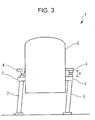
Fig. 3] Fig. 3 is a side view of a superconducting magnet apparatus. - [
Fig. 4] Fig. 4 is a side view of a superconducting magnet apparatus. - [
Fig. 5] Fig. 5 is a cross-sectional view taken along a line B - B ofFig. 4 . - [
Fig. 6] Fig. 6 is a side view of a superconducting magnet apparatus. - [
Fig. 7] Fig. 7 is a side view of a superconducting magnet apparatus. - Exemplary embodiments of the present invention are described below with reference to the accompanying drawings.
- According to a first embodiment of the present invention, as illustrated in
Fig. 1 , asuperconducting magnet apparatus 1 includes amain body 2 having a superconducting magnet disposed therein, three brackets 4 (one not illustrated) each protruding from a side surface of themain body 2, three stands (legs) 3 each supporting one of the threebrackets 4 from beneath (one not illustrated), and three surroundingmembers 5 attached to the side surface of the main body 2 (one not illustrated). - The
main body 2 is cylindrical in shape. In the central portion of themain body 2, a space that extends in the vertical direction and that allows sample probe (not illustrated) to be inserted thereinto from beneath is formed. - The three
brackets 4 are disposed so as to protrude from the side surface of themain body 2 at different locations in the circumferential direction of themain body 2 and, more specifically, at intervals of 120°. Note that the number of thebrackets 4 is not limited to three. - The
stand 3 is provided for each of thebrackets 4. Thestand 3 supports thebracket 4 from beneath so that a space is formed under themain body 2. In this manner, themain body 2 is supported by thestands 3 via thebrackets 4. In addition, thestands 3 are formed from, for example, air dampers that have a vibration isolation function and, thus, prevent vibration from being transferred from the outside to the superconducting magnet in themain body 2. The lower end of each of thestands 3 is bolted on a floor. Note that the number of thestands 3 is not limited to three if the number of thestands 3 is the same as that of thebrackets 4. - In addition, the surrounding
member 5 is provided on each of thebrackets 4. The surroundingmember 5 is attached to the side surface of themain body 2 at predetermined distance of "a" below thebracket 4. Note that the number of the surroundingmembers 5 is not limited to three if the number of the surroundingmembers 5 is the same as that of thebrackets 4. - As illustrated in
Fig. 2 , which is a cross-sectional view taken along a line A - A ofFig. 1 , the surroundingmember 5 has a U-shape in cross section. Part of the inner surface of the surroundingmember 5 surrounds the periphery of thestand 3 in a non-contact state. In this manner, by inhibiting the surroundingmember 5 from contacting with thestand 3, the surroundingmember 5 does not impair the vibration isolation function of thestand 3. In addition, vibration that is transferred via thestand 3 is not further transferred to themain body 2 via the surroundingmember 5. According to the present embodiment, the smallest distance b between thestand 3 and the surroundingmember 5 is 10 mm. - Referring back to
Fig. 1 , the predetermined distance a, which is the distance between thebracket 4 and the surroundingmember 5, is set so that even when themain body 2 bounces on thestand 3 due to strong vibration, such as earthquake, thestand 3 does not come off from the surroundingmember 5. According to the present embodiment, the predetermined distance a is set to a value greater than or equal to 40 mm. - In addition, as illustrated in
Fig. 3 , if thestand 3 is tilted due to strong vibration, such as earthquake, thestand 3 that is tilted is brought into contact with the inner surface of the surroundingmember 5. Thus, the tilt angle of thestand 3 is regulated so as to be within a margin of safety. - In addition, the surrounding
member 5 is removable from themain body 2. When thesuperconducting magnet apparatus 1 is assembled, thebrackets 4 are placed on the three stands 3 accurately positioned relative to one another. After themain body 2 is supported in this manner, the surroundingmembers 5 are attached to the side surface of themain body 2 by, for example, bolts. By attaching the surroundingmembers 5 to the side surface of themain body 2 after themain body 2 is supported by thestands 3 in this manner, thestands 3 need not be inserted into the inside of the surroundingmembers 5 when thebrackets 4 are placed on thestands 3 from above thestands 3. Accordingly, the assembling operation is facilitated. In addition, when thesuperconducting magnet apparatus 1 is disassembled, the surroundingmembers 5 are removed from the side surface of themain body 2 before themain body 2 is hoisted from the threestands 3 using, for example, a crane. Since the surroundingmembers 5 are removed from the side surface of themain body 2 before themain body 2 is hoisted from thestands 3 in this manner, each of the surroundingmembers 5 does not hit thestand 3 when themain body 2 is hoisted. Accordingly, the disassembling operation is facilitated. - According to such a configuration, even when strong vibration, such as earthquake, occurs and, thus, the
main body 2 bounces on thestands 3 and moves in the horizontal direction, the moving range of themain body 2 relative to thestands 3 is limited, since part of the inner surface of the surroundingmember 5 surrounds thestand 3 in a non-contact state. In addition, the surroundingmember 5 is disposed below thebracket 4 at such a predetermined distance a from thebracket 4 that thestand 3 does not come off from the surroundingmember 5. Accordingly, thestand 3 does not come off from the surroundingmember 5. Since thebracket 4 does not come off from thestand 3, themain body 2 does not fall down. - In addition, as illustrated in
Fig. 3 , even when strong vibration, such as earthquake, occurs and, thus, thestand 3 is tilted, the tilt angle of thestand 3 can be regulated so as to be within a margin of safety, since thestand 3 that is tilted is brought into contact with the inner surface of the surroundingmember 5. Since thestand 3 is not tilted at such an angle that themain body 2 falls down, themain body 2 does not fall down. - In addition, the state of the
stands 3 can be observed through a gap between thebracket 4 and the surroundingmember 5. Accordingly, if the stands 3 is, for example, an air damper, the operating state of thestand 3 can be examined at a maintenance time. - Note that the shape of the cross-section of the surrounding
member 5 is not limited to a U-shape. For example, the shape may be circular. In such a case, an additional member that connects the surroundingmember 5 having a cylindrical shape to themain body 2 having a cylindrical shape may be provided. Alternatively, the surroundingmember 5 may be integrated with themain body 2. Since the entire inner surface of the surroundingmember 5 having a cylindrical shape surrounds the periphery of thestand 3 in a non-contact state, the moving range of themain body 2 relative to thestands 3 is more narrowly regulated. In addition, thestand 3 that is tilted is in suitable contact with the inner surface of the surroundingmembers 5. - As described above, according to the
superconducting magnet apparatus 1 of the present embodiment, since at least part of the inner surface of the surroundingmember 5 surrounds the periphery of thestand 3 in a non-contact state, the moving range of themain body 2 relative to thestand 3 is regulated. In addition, the surroundingmember 5 and thebracket 4 are disposed at a predetermined distance a from each other. In this manner, even when themain body 2 bounces on thestands 3 due to strong vibration, such as earthquake, thestands 3 do not come off from the surroundingmembers 5. Accordingly, even when strong vibration, such as earthquake, occurs and themain body 2 bounces on thestands 3 and moves in the horizontal direction, thebrackets 4 do not come off from thestands 3. In addition, even when thestand 3 is tilted due to strong vibration, such as earthquake, thestand 3 that is tilted is brought into contact with the inner surface of the surroundingmember 5. Thus, the tilt angle of thestand 3 is regulated so as to be within a margin of safety. Consequently, even when the strong vibration, such as earthquake, occurs and thestand 3 is tilted, thestand 3 is not tilted at such an angle that themain body 2 falls down. In this manner, falling-off and damage of themain body 2 can be prevented. - A
superconducting magnet apparatus 201 according to a second embodiment of the present invention is described below. Unlike thesuperconducting magnet apparatus 1 according to the first embodiment, as illustrated inFig. 4 , thesuperconducting magnet apparatus 201 according to the present embodiment includes a surroundingmember 205 having a cylindrical shape instead of the surroundingmembers 5 having a U-shaped cross section. - The surrounding
member 205 is provided for each of thebrackets 4. In addition, the surroundingmember 205 is connected to the lower surface of thebracket 4. The surroundingmember 205 has a predetermined length c in the vertical direction so as to include a position at a predetermined distance below thebracket 4. - As illustrated in
Fig. 5 , which is a cross-sectional view taken along a line B - B ofFig. 4 , the surroundingmember 205 is circular in cross section. The inner surface of the surroundingmember 205 surrounds the periphery of thestand 3 in a non-contact state. In this manner, by inhibiting the surroundingmember 205 from contacting with thestand 3, the surroundingmember 205 does not impair the vibration isolation function of thestand 3. In addition, vibration that is transferred via thestand 3 is not further transferred to themain body 2 via the surroundingmember 205. According to the present embodiment, a distance d between thestand 3 and the surroundingmember 205 is 10 mm. - Referring back to
Fig. 4 , a predetermined length c is set to a length so that even when themain body 2 bounces on thestand 3 due to strong vibration, such as earthquake, thestand 3 does not come off from the surroundingmember 205. According to the present embodiment, the predetermined length c is set to a value greater than or equal to 40 mm. - In addition, as illustrated in
Fig. 6 , if thestand 3 is tilted due to strong vibration, such as earthquake, the tiltedstand 3 is brought into contact with the inner surface of the surroundingmember 205. Thus, the tilt angle of thestand 3 is regulated so as to be within a margin of safety. - According to such a configuration, even when strong vibration, such as earthquake, occurs and, thus, the
main body 2 bounces on thestands 3 and moves in the horizontal direction, the moving range of themain body 2 relative to thestands 3 is limited, since the inner surface of the surroundingmember 205 surrounds the periphery of thestand 3 in a non-contact state. In addition, the surroundingmember 205 has a predetermined length c that prevents thestand 3 from coming off from the surroundingmember 205 in the vertical direction. Accordingly, thestand 3 does not come off from the surroundingmember 205. Since thebracket 4 does not come off from thestand 3, themain body 2 does not fall down. - In addition, as illustrated in
Fig. 6 , even when strong vibration, such as earthquake, occurs and, thus, thestand 3 is tilted, the tilt angle of thestand 3 is regulated so as to be within a margin of safety, since thestand 3 that is tilted is brought into contact with the inner surface of the surroundingmember 205. Since thestand 3 is not tilted at such an angle that themain body 2 falls down, themain body 2 does not fall down. - As described above, according to the
superconducting magnet apparatus 201 of the present embodiment, since the inner surface of the surroundingmember 205 surrounds the periphery of thestand 3 in a non-contact state, the moving range of themain body 2 relative to thestand 3 is regulated. In addition, the surroundingmember 205 has a predetermined length c in the vertical direction. In this manner, even when themain body 2 bounces on thestands 3 due to strong vibration, such as earthquake, thestand 3 does not come off from the surroundingmember 205. Accordingly, even when strong vibration, such as earthquake, occurs and themain body 2 bounces on thestands 3 and moves in the horizontal direction, thebrackets 4 do not come off from thestands 3. In addition, even when thestand 3 is tilted due to strong vibration, such as earthquake, thestand 3 that is tilted is brought into contact with the inner surface of the surroundingmember 205. Thus, the tilt angle of thestand 3 is regulated so as to be within a margin of safety. Consequently, even when the strong vibration, such as earthquake, occurs and thestand 3 is tilted, thestand 3 is not tilted at such an angle that themain body 2 falls down. In this manner, falling-off and damage of themain body 2 can be prevented. - It should be noted that the above-described embodiments of the present invention are merely for illustrative purposes only and are not meant to be limiting on the scope of the present invention. The designs of the particular configurations can be modified as appropriate. In addition, the operations and effects described in the embodiments of the present invention are only exemplary operations and effects attainable by the present invention. The operations and effects of the present invention are not limited to those described in the embodiments of the present invention.
-
- 1, 201
- superconducting magnet apparatus
- 2
- main body
- 3
- stand (leg)
- 4
- bracket
- 5, 205
- surrounding member
Claims (3)
- A superconducting magnet apparatus (1,201) comprising:a main body (2) having a superconducting magnet therein;a plurality of brackets (4) disposed on a side surface of the main body (2) at different locations in a circumference direction of the side surface of the main body (2) so as to protrude from the side surface;a leg (3) provided for each of the brackets (4), each of said legs (3) supporting its corresponding bracket (4) from beneath so that a space is formed under the main body (2);characterized bya surrounding member (5,205) provided for each of the brackets (4), the surrounding member (5,205) being attached to the side surface of the main body (2) or a bottom surface of the corresponding bracket (4), at least part of an inner surface of the surrounding member (5,205) surrounding the periphery of the leg (3) in a non-contact state,wherein each surrounding member (5,205) is disposed so as to include a position at a predetermined distance below its corresponding bracket (4),wherein a tilt angle of each leg (3) is limited, in the sense that no leg (3) can be tilted beyond a certain angle at which it makes contact with an inner surface of the respective surrounding member (5,205), so that the main body (2) is prevented from falling down.
- The superconducting magnet apparatus (1,201) according to Claim 1, wherein each of the surrounding members (5,205) is attached to the side surface of the main body (2) at a predetermined distance below the corresponding bracket (4), and at least part of the inner surface surrounds the periphery of the leg (3) in a non-contact state.
- The superconducting magnet apparatus (1,201) according to Claim 1, wherein the surrounding member (5,205) is cylindrical in shape, and
wherein each of said surrounding members (5,205) is connected to a lower surface of the corresponding bracket (4) and has a predetermined length in a vertical direction, and the inner surface of each surrounding member (5,205) surrounds the periphery of the corresponding leg (3) in a non-contact state.
Applications Claiming Priority (2)
| Application Number | Priority Date | Filing Date | Title |
|---|---|---|---|
| JP2013052038A JP6004974B2 (en) | 2013-03-14 | 2013-03-14 | Superconducting magnet device |
| PCT/JP2014/055965 WO2014142027A1 (en) | 2013-03-14 | 2014-03-07 | Superconducting magnet device |
Publications (3)
| Publication Number | Publication Date |
|---|---|
| EP2975616A1 EP2975616A1 (en) | 2016-01-20 |
| EP2975616A4 EP2975616A4 (en) | 2016-11-30 |
| EP2975616B1 true EP2975616B1 (en) | 2017-11-29 |
Family
ID=51536687
Family Applications (1)
| Application Number | Title | Priority Date | Filing Date |
|---|---|---|---|
| EP14764124.5A Active EP2975616B1 (en) | 2013-03-14 | 2014-03-07 | Superconducting magnet device |
Country Status (5)
| Country | Link |
|---|---|
| US (1) | US9777883B2 (en) |
| EP (1) | EP2975616B1 (en) |
| JP (1) | JP6004974B2 (en) |
| CN (1) | CN105122393B (en) |
| WO (1) | WO2014142027A1 (en) |
Family Cites Families (15)
| Publication number | Priority date | Publication date | Assignee | Title |
|---|---|---|---|---|
| JPH079844B2 (en) * | 1988-03-24 | 1995-02-01 | 三菱重工業株式会社 | Superconducting coil insulation support device |
| JPH05243042A (en) | 1992-02-26 | 1993-09-21 | Hitachi Cable Ltd | Superconducting coil cooling device |
| JP3349539B2 (en) * | 1993-03-01 | 2002-11-25 | 株式会社日立製作所 | Insulated support device |
| US5726512A (en) * | 1996-10-04 | 1998-03-10 | The University Of Houston System | Vibration-free levitated platform |
| JP2002167947A (en) * | 2000-12-05 | 2002-06-11 | Fujita Corp | Vibration-proof support, method of supporting finished floor using vibration-proof support, and construction method |
| JP3891947B2 (en) * | 2003-03-07 | 2007-03-14 | ジーイー・メディカル・システムズ・グローバル・テクノロジー・カンパニー・エルエルシー | Magnetic resonance imaging device |
| JP2005203704A (en) * | 2004-01-19 | 2005-07-28 | Japan Superconductor Technology Inc | Superconducting magnet |
| DE102005041383B4 (en) * | 2005-09-01 | 2007-09-27 | Bruker Biospin Ag | NMR apparatus with co-cooled probe head and cryocontainer and method of operation thereof |
| JP4468388B2 (en) * | 2007-02-05 | 2010-05-26 | 株式会社日立製作所 | Magnetic field generator |
| CN201673752U (en) * | 2010-05-14 | 2010-12-15 | 张志亮 | Superconductive magnet |
| CN102163481B (en) * | 2011-02-16 | 2012-09-05 | 中国科学院等离子体物理研究所 | Supporting leg structure of superconducting Tokamak longitudinal field coil |
| DE102011006164B8 (en) * | 2011-03-25 | 2013-04-18 | Bruker Biospin Ag | Compact cryogenic NMR sensor with integrated, active cooling unit |
| US20130012393A1 (en) * | 2011-07-07 | 2013-01-10 | Daniel Bateman | Apparatus to confine a plurality of charged particles |
| GB2497342B (en) * | 2011-12-08 | 2014-06-18 | Siemens Plc | Vibration isolation for superconducting magnets |
| WO2015076054A1 (en) * | 2013-11-19 | 2015-05-28 | 株式会社 日立メディコ | Magnetic resonance imaging apparatus |
-
2013
- 2013-03-14 JP JP2013052038A patent/JP6004974B2/en active Active
-
2014
- 2014-03-07 EP EP14764124.5A patent/EP2975616B1/en active Active
- 2014-03-07 WO PCT/JP2014/055965 patent/WO2014142027A1/en not_active Ceased
- 2014-03-07 CN CN201480013337.4A patent/CN105122393B/en active Active
- 2014-03-07 US US14/770,373 patent/US9777883B2/en active Active
Non-Patent Citations (1)
| Title |
|---|
| None * |
Also Published As
| Publication number | Publication date |
|---|---|
| US20160215921A1 (en) | 2016-07-28 |
| JP2014179437A (en) | 2014-09-25 |
| EP2975616A4 (en) | 2016-11-30 |
| EP2975616A1 (en) | 2016-01-20 |
| US9777883B2 (en) | 2017-10-03 |
| JP6004974B2 (en) | 2016-10-12 |
| WO2014142027A1 (en) | 2014-09-18 |
| CN105122393A (en) | 2015-12-02 |
| CN105122393B (en) | 2017-09-29 |
Similar Documents
| Publication | Publication Date | Title |
|---|---|---|
| WO2008081808A1 (en) | Magnetic resonance inspecting apparatus | |
| KR101483779B1 (en) | Point displacement measuring instrument for bridge | |
| KR20160062975A (en) | Mounting apparatus for hydrostatic pressure test of specimen and method for pressure test using the same | |
| US20170030224A1 (en) | Handling device | |
| CN205484753U (en) | Gradient coil of magnetic resonance imaging device and magnetic resonance imaging device thereof | |
| JP2019531112A5 (en) | ||
| US9012792B2 (en) | Pin mounting for tension weighing module where the middle portion of the pins have arc-shapped retractable necks that couple with convex shaped portions of through holes in the sensing body | |
| US9777883B2 (en) | Superconducting magnet apparatus | |
| US20140096354A1 (en) | Service apparatus for turbomachine | |
| CN109887705B (en) | Electromagnet assembly | |
| KR200479612Y1 (en) | Distance measuring system for alignment of attachment burner and combuster chamber for gas turbine | |
| KR101043140B1 (en) | Accelerator handlers for electronic device testing | |
| CN102811662A (en) | Top plate for magnetic resonance imaging apparatus, bracket for installing top plate of magnetic resonance imaging apparatus, and magnetic resonance imaging apparatus | |
| US9599684B2 (en) | Mounting for a body coil of a magnetic resonance device | |
| KR101104868B1 (en) | Distribution plate of transformer drawout substation line | |
| Takechi et al. | Impaired memory following repeated pentylenetetrazol treatments in kindled mice | |
| KR200465978Y1 (en) | Cable tray supporter and ship having the same | |
| US10711852B1 (en) | Locking clutch systems | |
| Podewitz et al. | Spin interactions in cluster chemistry | |
| CN108777206B (en) | Nuclear magnetic resonance superconducting magnet | |
| CN201135921Y (en) | A hanging device for iron remover | |
| CN205831789U (en) | Magnetic resonance imaging device | |
| JP6326644B2 (en) | Base conveyor | |
| DE602006019908D1 (en) | EQUIPMENT LIFTING ARRANGEMENTS | |
| CN216646837U (en) | Aftershock monitoring equipment for earthquake |
Legal Events
| Date | Code | Title | Description |
|---|---|---|---|
| PUAI | Public reference made under article 153(3) epc to a published international application that has entered the european phase |
Free format text: ORIGINAL CODE: 0009012 |
|
| 17P | Request for examination filed |
Effective date: 20150917 |
|
| AK | Designated contracting states |
Kind code of ref document: A1 Designated state(s): AL AT BE BG CH CY CZ DE DK EE ES FI FR GB GR HR HU IE IS IT LI LT LU LV MC MK MT NL NO PL PT RO RS SE SI SK SM TR |
|
| AX | Request for extension of the european patent |
Extension state: BA ME |
|
| DAX | Request for extension of the european patent (deleted) | ||
| RIN1 | Information on inventor provided before grant (corrected) |
Inventor name: YOSHIKAWA, MASATOSHI Inventor name: TAGO, KAZUHITO Inventor name: OKUI, YOSHIO |
|
| RIC1 | Information provided on ipc code assigned before grant |
Ipc: G01R 33/3815 20060101ALN20161019BHEP Ipc: H01F 6/00 20060101ALI20161019BHEP Ipc: G01R 33/38 20060101AFI20161019BHEP |
|
| A4 | Supplementary search report drawn up and despatched |
Effective date: 20161027 |
|
| REG | Reference to a national code |
Ref country code: DE Ref legal event code: R079 Ref document number: 602014017946 Country of ref document: DE Free format text: PREVIOUS MAIN CLASS: H01F0006000000 Ipc: G01R0033380000 |
|
| GRAP | Despatch of communication of intention to grant a patent |
Free format text: ORIGINAL CODE: EPIDOSNIGR1 |
|
| RIC1 | Information provided on ipc code assigned before grant |
Ipc: H01F 6/00 20060101ALI20170522BHEP Ipc: G01R 33/38 20060101AFI20170522BHEP Ipc: G01R 33/3815 20060101ALN20170522BHEP |
|
| RIC1 | Information provided on ipc code assigned before grant |
Ipc: H01F 6/00 20060101ALI20170530BHEP Ipc: G01R 33/38 20060101AFI20170530BHEP Ipc: G01R 33/3815 20060101ALN20170530BHEP |
|
| INTG | Intention to grant announced |
Effective date: 20170628 |
|
| GRAS | Grant fee paid |
Free format text: ORIGINAL CODE: EPIDOSNIGR3 |
|
| GRAA | (expected) grant |
Free format text: ORIGINAL CODE: 0009210 |
|
| AK | Designated contracting states |
Kind code of ref document: B1 Designated state(s): AL AT BE BG CH CY CZ DE DK EE ES FI FR GB GR HR HU IE IS IT LI LT LU LV MC MK MT NL NO PL PT RO RS SE SI SK SM TR |
|
| REG | Reference to a national code |
Ref country code: CH Ref legal event code: EP |
|
| REG | Reference to a national code |
Ref country code: AT Ref legal event code: REF Ref document number: 950885 Country of ref document: AT Kind code of ref document: T Effective date: 20171215 |
|
| REG | Reference to a national code |
Ref country code: IE Ref legal event code: FG4D |
|
| REG | Reference to a national code |
Ref country code: DE Ref legal event code: R096 Ref document number: 602014017946 Country of ref document: DE |
|
| REG | Reference to a national code |
Ref country code: FR Ref legal event code: PLFP Year of fee payment: 5 |
|
| REG | Reference to a national code |
Ref country code: NL Ref legal event code: MP Effective date: 20171129 |
|
| REG | Reference to a national code |
Ref country code: LT Ref legal event code: MG4D |
|
| REG | Reference to a national code |
Ref country code: AT Ref legal event code: MK05 Ref document number: 950885 Country of ref document: AT Kind code of ref document: T Effective date: 20171129 |
|
| PG25 | Lapsed in a contracting state [announced via postgrant information from national office to epo] |
Ref country code: SE Free format text: LAPSE BECAUSE OF FAILURE TO SUBMIT A TRANSLATION OF THE DESCRIPTION OR TO PAY THE FEE WITHIN THE PRESCRIBED TIME-LIMIT Effective date: 20171129 Ref country code: ES Free format text: LAPSE BECAUSE OF FAILURE TO SUBMIT A TRANSLATION OF THE DESCRIPTION OR TO PAY THE FEE WITHIN THE PRESCRIBED TIME-LIMIT Effective date: 20171129 Ref country code: NO Free format text: LAPSE BECAUSE OF FAILURE TO SUBMIT A TRANSLATION OF THE DESCRIPTION OR TO PAY THE FEE WITHIN THE PRESCRIBED TIME-LIMIT Effective date: 20180228 Ref country code: LT Free format text: LAPSE BECAUSE OF FAILURE TO SUBMIT A TRANSLATION OF THE DESCRIPTION OR TO PAY THE FEE WITHIN THE PRESCRIBED TIME-LIMIT Effective date: 20171129 Ref country code: FI Free format text: LAPSE BECAUSE OF FAILURE TO SUBMIT A TRANSLATION OF THE DESCRIPTION OR TO PAY THE FEE WITHIN THE PRESCRIBED TIME-LIMIT Effective date: 20171129 |
|
| PG25 | Lapsed in a contracting state [announced via postgrant information from national office to epo] |
Ref country code: LV Free format text: LAPSE BECAUSE OF FAILURE TO SUBMIT A TRANSLATION OF THE DESCRIPTION OR TO PAY THE FEE WITHIN THE PRESCRIBED TIME-LIMIT Effective date: 20171129 Ref country code: AT Free format text: LAPSE BECAUSE OF FAILURE TO SUBMIT A TRANSLATION OF THE DESCRIPTION OR TO PAY THE FEE WITHIN THE PRESCRIBED TIME-LIMIT Effective date: 20171129 Ref country code: HR Free format text: LAPSE BECAUSE OF FAILURE TO SUBMIT A TRANSLATION OF THE DESCRIPTION OR TO PAY THE FEE WITHIN THE PRESCRIBED TIME-LIMIT Effective date: 20171129 Ref country code: GR Free format text: LAPSE BECAUSE OF FAILURE TO SUBMIT A TRANSLATION OF THE DESCRIPTION OR TO PAY THE FEE WITHIN THE PRESCRIBED TIME-LIMIT Effective date: 20180301 Ref country code: BG Free format text: LAPSE BECAUSE OF FAILURE TO SUBMIT A TRANSLATION OF THE DESCRIPTION OR TO PAY THE FEE WITHIN THE PRESCRIBED TIME-LIMIT Effective date: 20180228 Ref country code: RS Free format text: LAPSE BECAUSE OF FAILURE TO SUBMIT A TRANSLATION OF THE DESCRIPTION OR TO PAY THE FEE WITHIN THE PRESCRIBED TIME-LIMIT Effective date: 20171129 |
|
| PG25 | Lapsed in a contracting state [announced via postgrant information from national office to epo] |
Ref country code: NL Free format text: LAPSE BECAUSE OF FAILURE TO SUBMIT A TRANSLATION OF THE DESCRIPTION OR TO PAY THE FEE WITHIN THE PRESCRIBED TIME-LIMIT Effective date: 20171129 |
|
| PG25 | Lapsed in a contracting state [announced via postgrant information from national office to epo] |
Ref country code: EE Free format text: LAPSE BECAUSE OF FAILURE TO SUBMIT A TRANSLATION OF THE DESCRIPTION OR TO PAY THE FEE WITHIN THE PRESCRIBED TIME-LIMIT Effective date: 20171129 Ref country code: DK Free format text: LAPSE BECAUSE OF FAILURE TO SUBMIT A TRANSLATION OF THE DESCRIPTION OR TO PAY THE FEE WITHIN THE PRESCRIBED TIME-LIMIT Effective date: 20171129 Ref country code: SK Free format text: LAPSE BECAUSE OF FAILURE TO SUBMIT A TRANSLATION OF THE DESCRIPTION OR TO PAY THE FEE WITHIN THE PRESCRIBED TIME-LIMIT Effective date: 20171129 Ref country code: CY Free format text: LAPSE BECAUSE OF FAILURE TO SUBMIT A TRANSLATION OF THE DESCRIPTION OR TO PAY THE FEE WITHIN THE PRESCRIBED TIME-LIMIT Effective date: 20171129 |
|
| REG | Reference to a national code |
Ref country code: DE Ref legal event code: R097 Ref document number: 602014017946 Country of ref document: DE |
|
| PG25 | Lapsed in a contracting state [announced via postgrant information from national office to epo] |
Ref country code: PL Free format text: LAPSE BECAUSE OF FAILURE TO SUBMIT A TRANSLATION OF THE DESCRIPTION OR TO PAY THE FEE WITHIN THE PRESCRIBED TIME-LIMIT Effective date: 20171129 Ref country code: RO Free format text: LAPSE BECAUSE OF FAILURE TO SUBMIT A TRANSLATION OF THE DESCRIPTION OR TO PAY THE FEE WITHIN THE PRESCRIBED TIME-LIMIT Effective date: 20171129 Ref country code: SM Free format text: LAPSE BECAUSE OF FAILURE TO SUBMIT A TRANSLATION OF THE DESCRIPTION OR TO PAY THE FEE WITHIN THE PRESCRIBED TIME-LIMIT Effective date: 20171129 |
|
| PLBE | No opposition filed within time limit |
Free format text: ORIGINAL CODE: 0009261 |
|
| STAA | Information on the status of an ep patent application or granted ep patent |
Free format text: STATUS: NO OPPOSITION FILED WITHIN TIME LIMIT |
|
| REG | Reference to a national code |
Ref country code: CH Ref legal event code: PL |
|
| 26N | No opposition filed |
Effective date: 20180830 |
|
| PG25 | Lapsed in a contracting state [announced via postgrant information from national office to epo] |
Ref country code: SI Free format text: LAPSE BECAUSE OF FAILURE TO SUBMIT A TRANSLATION OF THE DESCRIPTION OR TO PAY THE FEE WITHIN THE PRESCRIBED TIME-LIMIT Effective date: 20171129 Ref country code: MC Free format text: LAPSE BECAUSE OF FAILURE TO SUBMIT A TRANSLATION OF THE DESCRIPTION OR TO PAY THE FEE WITHIN THE PRESCRIBED TIME-LIMIT Effective date: 20171129 |
|
| REG | Reference to a national code |
Ref country code: IE Ref legal event code: MM4A |
|
| PG25 | Lapsed in a contracting state [announced via postgrant information from national office to epo] |
Ref country code: LU Free format text: LAPSE BECAUSE OF NON-PAYMENT OF DUE FEES Effective date: 20180307 |
|
| PG25 | Lapsed in a contracting state [announced via postgrant information from national office to epo] |
Ref country code: IE Free format text: LAPSE BECAUSE OF NON-PAYMENT OF DUE FEES Effective date: 20180307 |
|
| PG25 | Lapsed in a contracting state [announced via postgrant information from national office to epo] |
Ref country code: LI Free format text: LAPSE BECAUSE OF NON-PAYMENT OF DUE FEES Effective date: 20180331 Ref country code: CH Free format text: LAPSE BECAUSE OF NON-PAYMENT OF DUE FEES Effective date: 20180331 |
|
| PG25 | Lapsed in a contracting state [announced via postgrant information from national office to epo] |
Ref country code: MT Free format text: LAPSE BECAUSE OF NON-PAYMENT OF DUE FEES Effective date: 20180307 |
|
| PG25 | Lapsed in a contracting state [announced via postgrant information from national office to epo] |
Ref country code: TR Free format text: LAPSE BECAUSE OF FAILURE TO SUBMIT A TRANSLATION OF THE DESCRIPTION OR TO PAY THE FEE WITHIN THE PRESCRIBED TIME-LIMIT Effective date: 20171129 |
|
| PG25 | Lapsed in a contracting state [announced via postgrant information from national office to epo] |
Ref country code: PT Free format text: LAPSE BECAUSE OF FAILURE TO SUBMIT A TRANSLATION OF THE DESCRIPTION OR TO PAY THE FEE WITHIN THE PRESCRIBED TIME-LIMIT Effective date: 20171129 |
|
| PG25 | Lapsed in a contracting state [announced via postgrant information from national office to epo] |
Ref country code: HU Free format text: LAPSE BECAUSE OF FAILURE TO SUBMIT A TRANSLATION OF THE DESCRIPTION OR TO PAY THE FEE WITHIN THE PRESCRIBED TIME-LIMIT; INVALID AB INITIO Effective date: 20140307 Ref country code: MK Free format text: LAPSE BECAUSE OF NON-PAYMENT OF DUE FEES Effective date: 20171129 |
|
| PG25 | Lapsed in a contracting state [announced via postgrant information from national office to epo] |
Ref country code: AL Free format text: LAPSE BECAUSE OF FAILURE TO SUBMIT A TRANSLATION OF THE DESCRIPTION OR TO PAY THE FEE WITHIN THE PRESCRIBED TIME-LIMIT Effective date: 20171129 Ref country code: IS Free format text: LAPSE BECAUSE OF FAILURE TO SUBMIT A TRANSLATION OF THE DESCRIPTION OR TO PAY THE FEE WITHIN THE PRESCRIBED TIME-LIMIT Effective date: 20180329 |
|
| P01 | Opt-out of the competence of the unified patent court (upc) registered |
Effective date: 20230523 |
|
| REG | Reference to a national code |
Ref country code: DE Ref legal event code: R081 Ref document number: 602014017946 Country of ref document: DE Owner name: JEOL LTD., JP Free format text: FORMER OWNER: JAPAN SUPERCONDUCTOR TECHNOLOGY INC., KOBE, HYOGO, JP Ref country code: DE Ref legal event code: R082 Ref document number: 602014017946 Country of ref document: DE Representative=s name: DENNEMEYER & ASSOCIATES S.A., DE |
|
| REG | Reference to a national code |
Ref country code: GB Ref legal event code: 732E Free format text: REGISTERED BETWEEN 20250911 AND 20250917 |
|
| REG | Reference to a national code |
Ref country code: BE Ref legal event code: PD Owner name: JEOL LTD.; JP Free format text: DETAILS ASSIGNMENT: CHANGE OF OWNER(S), ASSIGNMENT; FORMER OWNER NAME: JAPAN SUPERCONDUCTOR TECHNOLOGY, INC. Effective date: 20250925 |
|
| PGFP | Annual fee paid to national office [announced via postgrant information from national office to epo] |
Ref country code: GB Payment date: 20260202 Year of fee payment: 13 |
|
| PGFP | Annual fee paid to national office [announced via postgrant information from national office to epo] |
Ref country code: DE Payment date: 20260128 Year of fee payment: 13 |
|
| PGFP | Annual fee paid to national office [announced via postgrant information from national office to epo] |
Ref country code: BE Payment date: 20260217 Year of fee payment: 13 Ref country code: IT Payment date: 20260220 Year of fee payment: 13 |
|
| PGFP | Annual fee paid to national office [announced via postgrant information from national office to epo] |
Ref country code: FR Payment date: 20260209 Year of fee payment: 13 |
|
| PGFP | Annual fee paid to national office [announced via postgrant information from national office to epo] |
Ref country code: CZ Payment date: 20260219 Year of fee payment: 13 |