EP2975580A2 - Method and system for providing visual feedback in a virtual reality environment - Google Patents
Method and system for providing visual feedback in a virtual reality environment Download PDFInfo
- Publication number
- EP2975580A2 EP2975580A2 EP15159379.5A EP15159379A EP2975580A2 EP 2975580 A2 EP2975580 A2 EP 2975580A2 EP 15159379 A EP15159379 A EP 15159379A EP 2975580 A2 EP2975580 A2 EP 2975580A2
- Authority
- EP
- European Patent Office
- Prior art keywords
- user
- virtual object
- depth
- virtual
- distance
- Prior art date
- Legal status (The legal status is an assumption and is not a legal conclusion. Google has not performed a legal analysis and makes no representation as to the accuracy of the status listed.)
- Granted
Links
Images


Classifications
-
- G—PHYSICS
- G06—COMPUTING OR CALCULATING; COUNTING
- G06T—IMAGE DATA PROCESSING OR GENERATION, IN GENERAL
- G06T15/00—Three-dimensional [3D] image rendering
- G06T15/50—Lighting effects
- G06T15/60—Shadow generation
-
- G—PHYSICS
- G06—COMPUTING OR CALCULATING; COUNTING
- G06F—ELECTRIC DIGITAL DATA PROCESSING
- G06F3/00—Input arrangements for transferring data to be processed into a form capable of being handled by the computer; Output arrangements for transferring data from processing unit to output unit, e.g. interface arrangements
- G06F3/01—Input arrangements or combined input and output arrangements for interaction between user and computer
- G06F3/011—Arrangements for interaction with the human body, e.g. for user immersion in virtual reality
-
- G—PHYSICS
- G06—COMPUTING OR CALCULATING; COUNTING
- G06F—ELECTRIC DIGITAL DATA PROCESSING
- G06F3/00—Input arrangements for transferring data to be processed into a form capable of being handled by the computer; Output arrangements for transferring data from processing unit to output unit, e.g. interface arrangements
- G06F3/01—Input arrangements or combined input and output arrangements for interaction between user and computer
- G06F3/03—Arrangements for converting the position or the displacement of a member into a coded form
- G06F3/0304—Detection arrangements using opto-electronic means
-
- G—PHYSICS
- G06—COMPUTING OR CALCULATING; COUNTING
- G06F—ELECTRIC DIGITAL DATA PROCESSING
- G06F3/00—Input arrangements for transferring data to be processed into a form capable of being handled by the computer; Output arrangements for transferring data from processing unit to output unit, e.g. interface arrangements
- G06F3/01—Input arrangements or combined input and output arrangements for interaction between user and computer
- G06F3/048—Interaction techniques based on graphical user interfaces [GUI]
- G06F3/0481—Interaction techniques based on graphical user interfaces [GUI] based on specific properties of the displayed interaction object or a metaphor-based environment, e.g. interaction with desktop elements like windows or icons, or assisted by a cursor's changing behaviour or appearance
- G06F3/04815—Interaction with a metaphor-based environment or interaction object displayed as three-dimensional [3D], e.g. changing the user viewpoint with respect to the environment or object
Definitions
- a viewer may perceive being physically present in a non-physical world.
- the perception may be created by surrounding the viewer with 3-dimensional images, sound and other stimuli that provide an "immersive" environment.
- Off-axis perspective projection techniques may use head tracking to calculate perspective view from the location of the viewer. Then, these inputs may be used for the perspective simulation of a camera in a virtual environment. This visual simulation puts the viewer in to an illusion that the viewer is surrounded by floating objects of the immersive virtual environment.
- a non-transitory, computer-readable medium storing instructions that, when executed by a processor, causes the processor to perform operations to provide visual feedback to a user in a virtual reality environment is disclosed.
- a potential point of interaction between the user and the virtual environment may be determined at step 104.
- the depth information of the user may be used to determine when a user moves to interact with the virtual environment.
- the user may interact with the virtual world with various body parts, including, palms, elbows, knees, feet, head, etc.
- a user's interaction with the virtual environment may include, but is not limited to, reaching out to touch a virtual 3D object, grabbing a virtual object, pushing a virtual object, punching a virtual object, kicking a virtual object, etc.
- FIG. 2(d) illustrates the step of determining the depth of the user from depth sensor 204. Based on the depth or distance information of the user relative to depth sensor 204, the potential point of interaction of the user with the scene rendered may be determined. In FIG. 2(d) , it may be determined that the user intends to interact with 3D virtual object 206. Further, it may be determined that the user intends to interact with the left and right sides of virtual object 206. Thereafter, a depth map of 3D virtual object 206 may be determined from the perspective of the depth sensor. A virtual depth camera may be used to determine the depth of the 3D virtual object 206. The process of determining the depth of the user and the virtual object is explained in detail in conjunction with FIG. 1 .
- the instructions stored in memory 304 may further include instructions to receive depth of the 3D virtual object at the interaction point.
- a virtual depth camera may determine the depth of the virtual object as explained in conjunction with FIG. 1 .
- Processor 302 may use the depth information of the user and the depth information of the virtual object to calculate a distance between the user and the virtual object. Thereafter, based on the distance between the user and the virtual object, processor 302 may render a soft shadow on the virtual object. In effect, a soft shadow corresponding to the body part(s) of the user interacting with the virtual environment may be rendered. To render the soft shadow, processor 302 may refer a predefined color look-up table. The predefined color look-up table may be used to convert the difference in depth information to a black color image with alpha transparency. Further, a spatially variant blur effect may be applied to the black color image. The radius of the blur may vary according to the distance (difference in depth) at that particular pixel as explained in conjunction with FIG. 1 .
- the processor may include a microprocessor, such as AMD Athlon, Duron or Opteron, ARM's application, embedded or secure processors, IBM PowerPC, Intel's Core, Itanium, Xeon, Celeron or other line of processors, etc.
- the processor 402 may be implemented using mainframe, distributed processor, multi-core, parallel, grid, or other architectures. Some embodiments may utilize embedded technologies like application-specific integrated circuits (ASICs), digital signal processors (DSPs), Field Programmable Gate Arrays (FPGAs), etc.
- ASICs application-specific integrated circuits
- DSPs digital signal processors
- FPGAs Field Programmable Gate Arrays
- I/O Processor 402 may be disposed in communication with one or more input/output (I/O) devices via I/O interface 403.
- the I/O interface 403 may employ communication protocols/methods such as, without limitation, audio, analog, digital, monoaural, RCA, stereo, IEEE-1394, serial bus, universal serial bus (USB), infrared, PS/2, BNC, coaxial, component, composite, digital visual interface (DVI), high-definition multimedia interface (HDMI), RF antennas, S-Video, VGA, IEEE 802.n /b/g/n/x, Bluetooth, cellular (e.g., code-division multiple access (CDMA), high-speed packet access (HSPA+), global system for mobile communications (GSM), long-term evolution (LTE), WiMax, or the like), etc.
- CDMA code-division multiple access
- HSPA+ high-speed packet access
- GSM global system for mobile communications
- LTE long-term evolution
- WiMax wireless wide area network
- the transceiver may include an antenna operatively connected to a transceiver chip (e.g., Texas Instruments WiLink WL1283, Broadcom BCM4750IUB8, Infineon Technologies X-Gold 618-PMB9800, or the like), providing IEEE 802.11 a/b/g/n, Bluetooth, FM, global positioning system (GPS), 2G/3G HSDPA/HSUPA communications, etc.
- a transceiver chip e.g., Texas Instruments WiLink WL1283, Broadcom BCM4750IUB8, Infineon Technologies X-Gold 618-PMB9800, or the like
- IEEE 802.11 a/b/g/n e.g., Texas Instruments WiLink WL1283, Broadcom BCM4750IUB8, Infineon Technologies X-Gold 618-PMB9800, or the like
- IEEE 802.11 a/b/g/n e.g., Texas Instruments WiLink WL1283, Broadcom BCM4750I
- These devices may include, without limitation, personal computer(s), server(s), fax machines, printers, scanners, various mobile devices such as cellular telephones, smartphones (e.g., Apple iPhone, Blackberry, Android-based phones, etc.), tablet computers, eBook readers (Amazon Kindle, Nook, etc.), laptop computers, notebooks, gaming consoles (Microsoft Xbox, Nintendo DS, Sony PlayStation, etc.), or the like.
- the computer system 401 may itself embody one or more of these devices.
- Operating systems include, without limitation, Apple Macintosh OS X, Unix, Unix-like system distributions (e.g., Berkeley Software Distribution (BSD), FreeBSD, NetBSD, OpenBSD, etc.), Linux distributions (e.g., Red Hat, Ubuntu, Kubuntu, etc.), IBM OS/2, Microsoft Windows (XP, Vista/7/8, etc.), Apple iOS, Google Android, Blackberry OS, or the like.
- User interface 417 may facilitate display, execution, interaction, manipulation, or operation of program components through textual or graphical facilities.
- user interfaces may provide computer interaction interface elements on a display system operatively connected to the computer system 401, such as cursors, icons, check boxes, menus, scrollers, windows, widgets, etc.
- the computer system 401 may implement a web browser 418 stored program component.
- the web browser may be a hypertext viewing application, such as Microsoft Internet Explorer, Google Chrome, Mozilla Firefox, Apple Safari, etc. Secure web browsing may be provided using HTTPS (secure hypertext transport protocol), secure sockets layer (SSL), Transport Layer Security (TLS), etc. Web browsers may utilize facilities such as AJAX, DHTML, Adobe Flash, JavaScript, Java, application programming interfaces (APIs), etc.
- the computer system 401 may implement a mail server 419 stored program component.
- the mail server may be an Internet mail server such as Microsoft Exchange, or the like.
- computer system 401 may store user/application data 421, such as the data, variables, records, etc. (e.g., user depth information matrix and virtual depth information matrix) as described in this disclosure.
- databases may be implemented as fault-tolerant, relational, scalable, secure databases such as Oracle or Sybase.
- databases may be implemented using standardized data structures, such as an array, hash, linked list, struct, structured text file (e.g., XML), table, or as object-oriented databases (e.g., using ObjectStore, Poet, Zope, etc.).
- object-oriented databases e.g., using ObjectStore, Poet, Zope, etc.
- Such databases may be consolidated or distributed, sometimes among the various computer systems discussed above in this disclosure. It is to be understood that the structure and operation of the any computer or database component may be combined, consolidated, or distributed in any working combination.
- a computer-readable storage medium refers to any type of physical memory on which information or data readable by a processor may be stored.
- a computer-readable storage medium may store instructions for execution by one or more processors, including instructions for causing the processor(s) to perform steps or stages consistent with the embodiments described herein.
- the term "computer-readable medium” should be understood to include tangible items and exclude carrier waves and transient signals, i.e., be non-transitory. Examples include random access memory (RAM), read-only memory (ROM), volatile memory, nonvolatile memory, hard drives, CD ROMs, DVDs, flash drives, disks, and any other known physical storage media.
Landscapes
- Engineering & Computer Science (AREA)
- Theoretical Computer Science (AREA)
- General Engineering & Computer Science (AREA)
- Physics & Mathematics (AREA)
- General Physics & Mathematics (AREA)
- Human Computer Interaction (AREA)
- Computer Graphics (AREA)
- User Interface Of Digital Computer (AREA)
- Processing Or Creating Images (AREA)
Abstract
Description
- This disclosure relates generally to providing feedback to a user and more particularly to a method and system for providing visual feedback to a user in a virtual reality environment.
- In an immersive virtual environment, a viewer may perceive being physically present in a non-physical world. The perception may be created by surrounding the viewer with 3-dimensional images, sound and other stimuli that provide an "immersive" environment. Off-axis perspective projection techniques may use head tracking to calculate perspective view from the location of the viewer. Then, these inputs may be used for the perspective simulation of a camera in a virtual environment. This visual simulation puts the viewer in to an illusion that the viewer is surrounded by floating objects of the immersive virtual environment.
- Some applications of an immersive virtual environment may require the viewer to interact with objects of the virtual environment. However, interaction between a real world object (the viewer) with an object in the virtual world may not be seamless. This may be due to lack of feedback to the user when approaching or interacting with objects of the virtual world. For example, if the virtual environment allows the viewer to grab a particular object and move it, the viewer may not be able to intuitively determine the grab action as the viewer is grabbing a virtual object and not a real object.
- In one embodiment, a method of providing visual feedback to a user in a virtual reality environment is disclosed. The method may comprise: capturing position and depth information of the user using a depth sensor; determining a potential interaction point between the user and a 3D virtual object associated with the virtual reality environment based on the position and depth information of the user; determining, using a virtual depth camera, depth of the 3D virtual object at the potential interaction point; calculating a distance between the user and the 3D virtual object based on the position and depth information of the user and the depth of the 3D virtual object; and rendering a soft shadow of the user on the 3D virtual object based on the distance between the user and the 3D virtual object.
- In another embodiment, a system for providing visual feedback to a user in a virtual reality environment is disclosed. The system may comprise a processor and a memory disposed in communication with the processor and storing processor-executable instructions. The instructions may comprise instructions to: receive position and depth information of the user from a depth sensor; determine a potential interaction point between the user and a 3D virtual object associated with the virtual reality environment based on the position and depth information of the user; receive depth of the 3D virtual object at the potential interaction point from a virtual depth camera; calculate a distance between the user and the 3D virtual object based on the position and depth information of the user and the depth of the 3D virtual object; and render a soft shadow of the user on the 3D virtual object based on the distance between the user and the 3D virtual object.
- In another embodiment, a non-transitory, computer-readable medium storing instructions that, when executed by a processor, causes the processor to perform operations to provide visual feedback to a user in a virtual reality environment is disclosed.
- It is to be understood that both the foregoing general description and the following detailed description are exemplary and explanatory only and are not restrictive of the invention, as claimed.
- The accompanying drawings, which are incorporated in and constitute a part of this disclosure, illustrate exemplary embodiments and, together with the description, serve to explain the disclosed principles.
-
FIG. 1 illustrates a block diagram of a method of providing visual feedback to a user in a virtual environment according to some embodiments of the present disclosure. -
FIG. 2 illustrates an exemplary depiction of a method of providing visual feedback to a user in accordance with some embodiments of the present disclosure. -
FIG. 3 illustrates a system for providing visual feedback to a user in a virtual reality environment in accordance with some embodiments of the present disclosure. -
FIG. 4 is a block diagram of an exemplary computer system for implementing embodiments consistent with the present disclosure. - Exemplary embodiments are described with reference to the accompanying drawings. Wherever convenient, the same reference numbers are used throughout the drawings to refer to the same or like parts. While examples and features of disclosed principles are described herein, modifications, adaptations, and other implementations are possible without departing from the scope of the disclosed embodiments. It is intended that the following detailed description be considered as exemplary only, with the true scope being indicated by the following claims.
-
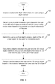
FIG. 1 illustrates a block diagram of a method of providing visual feedback to a user in a virtual environment according to some embodiments of the present disclosure. The virtual environment may be an immersive environment wherein the user may interact with objects displayed or projected on surfaces surrounding the user. An example of an immersive virtual environment could be Computer Assisted Virtual Environment (CAVE) where projectors may be directed to three, four, five, or six of the walls of a room. The projectors may project images on the different walls to give a user the perception of actually being present and involved in the virtual environment. The images projected on the different walls may give the user a perception of being surrounded by 3D objects that are floating around the user. - Immersive environments may track head or eye movements of the user and accordingly render a scene from the perspective of the user's head or eyes. For example, it may be possible for a user to walk around a 3D object rendered in the scene. As and when the user moves, the position of the head and eyes of the user may be considered to render the object in such as way as to provide a perception of immersion to the user. For example, if a 3D image of a car is projected in the virtual environment, the user may walk around the car and according to the user's position, the corresponding images of the car may be rendered. If, for example, the user wants to see the rear of the car, the user may walk around the 3D image of the car as though the car was actually physically present. As the user moves from the front of the car to the rear, the perspective of the user may be considered to render the car in such a way that the user has the perception of walking around an actual physical car.
- In order to provide visual feedback to a user when the user interacts with a virtual 3D object, position and depth information of the user may be captured at
step 102. The position and spatial depth of a user may be determined using a depth sensor. A depth sensor may include, among other components, an infrared (IR) projector and an IR camera. The IR projector may project a pattern of IR rays at the user and the IR camera may detect the rays reflected off the user. A processor associated with the depth sensor may process the pattern and determine the spatial position and depth of the user. The depth sensor may track the body joint positions and head positions of the user and accordingly determine movement of the user. For example, the depth sensor may determine if the user is approaching objects rendered in the virtual world or moving away from them. Similarly, the depth sensor may be able to determine if the user is reaching out using his hand or is waving etc. The depth sensor may be placed in front of the user and calibrated in such a way as to determine the spatial distance of the user with respect to the depth sensor. The depth sensor may capture an image or a video of the user and determine the distance of the user from the depth sensor from pixel information in the image or video. - Based on the position and depth information of the user, a potential point of interaction between the user and the virtual environment may be determined at
step 104. For example, the depth information of the user may be used to determine when a user moves to interact with the virtual environment. The user may interact with the virtual world with various body parts, including, palms, elbows, knees, feet, head, etc. A user's interaction with the virtual environment may include, but is not limited to, reaching out to touch a virtual 3D object, grabbing a virtual object, pushing a virtual object, punching a virtual object, kicking a virtual object, etc. - On determining the potential point of interaction between the user and a 3D virtual object, a spatial depth of the 3D virtual object at the potential point of interaction may be determined using a virtual depth camera at
step 106. In some embodiments, the virtual depth camera may be a Computer Graphics (CG) camera. In some embodiments, the virtual depth camera may capture the depth of the virtual object from the perspective of the depth sensor used to capture the position and depth of the user in order to have the same reference point for the depth of the user and the depth of the virtual object. A color depth map may be used to determine the depth of the 3D virtual object. The color depth map may be generated based on an assumption that pixels having similar colors are likely to have similar depths. Thus, a depth function relating a pixel's color to its depth from the reference point may be determined. The virtual depth camera may capture color information of the virtual object at the potential point of interaction and accordingly determine the object's depth. Further, the depth information of the object may help determine which surface of the virtual object is closest to the user. It is to be noted that the depth of the 3D virtual object may be determined in different ways by using different image processing algorithms to process the information captured by the virtual depth camera without deviating from the scope of the present disclosure. - The depth information of the user and the depth information of the virtual object at the potential point of interaction may be maintained as depth information matrices. A user depth information matrix corresponding to the depth information of the user may include pixel level information of the depth of the user. In other words, the user depth information matrix may include, for each pixel of an image captured by the depth sensor, a corresponding depth value. The depth value of a pixel may represent the distance of that pixel from the reference point (position of the depth sensor). Thus, the pixels corresponding to the background (behind the user) may be associated with a larger distance when compared to the pixels associated with the user. Also, not all the pixels of the image of the user may be associated with the same depth. For example, if the user is pointing with the index finger of the right hand, the pixels corresponding to the index finger may have a smaller distance compared to the right hand. The right hand would in turn have a smaller distance compared to the rest of the user's body.
- Similarly, a virtual depth information matrix may be maintained for the virtual object associated with the potential point of interaction. The virtual depth information matrix may include a pixel level depth of the various surfaces of the virtual object with respect to a reference point (position of the virtual depth camera).
- The user depth information matrix and the virtual depth information matrix may be used to calculate a distance between the user and the virtual object at
step 108. The distance between the user and the virtual object may be calculated, per pixel, as the difference between the depth value of the user and the depth value of the object at that pixel. Thus, this provides the distance information between the real-life object and the virtual object at each pixel. - A soft shadow of the user may be rendered on the virtual object based on the distance between the user and the virtual object at
step 110. In effect, a soft shadow corresponding to the body part(s) of the user interacting with the virtual environment may be rendered. Here, the soft shadows may be considered to be shadows formed by natural ambient lighting or diffused lighting conditions. They are sharper when objects are in contact and they become soft (defocused) and finally unseen as objects move apart. The user's body may act as an occlusion for natural ambient lighting and accordingly a soft shadow may be rendered on the virtual object that is subject to the interaction. - To render the soft shadow, a predefined color look-up table may be used. The predefined color look-up table may be used to convert the difference in depth information to a black color image with alpha transparency. Thus, the color look-up table may include entries that map a particular distance between the user and the virtual object to a particular shadow having a particular size and shade. Further, a spatially variant blur effect may be applied to the black color image. The radius of the blur may vary according to the distance (difference in depth) at that particular pixel. As the user moves closer to the virtual object, the shadow rendered may be smaller, sharper and darker. Comparatively, as the user moves away from the virtual object, the shadow rendered may be larger, blurrier, and lighter.
-
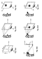
FIG. 2 illustrates an exemplary depiction of a method of providing visual feedback to a user in accordance with some embodiments of the present disclosure.FIG 2(a) illustrates a step of configuring a system for providing visual feedback to a user. The system may include one or more display screens such asdisplay screen 202 and adepth sensor 204. The system may further include one or more projectors (not shown inFIG. 2 ) that project a scene on the one or more displays. Configuring the system may include fixing the origin of reference coordinate system. Further, the configuration may include establishing a spatial relationship between the display screens (such as display screen 202) anddepth sensor 204 by configuring their placement, dimensions and orientations. Thus, the configuration of the system establishes a spatial relationship between all physical and virtual objects. - In
FIG. 2(b) , the user's head and eye position may be identified bydepth sensor 204 and accordingly the user's perspective may be determined. If more than one display screen is present, the user's perspective relative to each of the numerous display screens may be identified. Thereafter, using the user's perspective, the scene may be generated for visualization as shown inFIG. 2(c) . It is to be noted that although the scene inFIG. 2(c) depicts a single 3Dvirtual object 206, a plurality of 3D virtual objects may be rendered ondisplay screen 202. -
FIG. 2(d) illustrates the step of determining the depth of the user fromdepth sensor 204. Based on the depth or distance information of the user relative todepth sensor 204, the potential point of interaction of the user with the scene rendered may be determined. InFIG. 2(d) , it may be determined that the user intends to interact with 3Dvirtual object 206. Further, it may be determined that the user intends to interact with the left and right sides ofvirtual object 206. Thereafter, a depth map of 3Dvirtual object 206 may be determined from the perspective of the depth sensor. A virtual depth camera may be used to determine the depth of the 3Dvirtual object 206. The process of determining the depth of the user and the virtual object is explained in detail in conjunction withFIG. 1 . After determining the depths of the user and the virtual object from the perspective of the depth sensor, the difference in the distances between the user and the virtual object may be used to render a soft shadow of the user on thevirtual object 206. As the user moves closer to thevirtual object 206, the shadow rendered may get smaller, sharper and darker. Comparatively, as the user moves away from the virtual object, the shadow rendered on the virtual object may get larger, blurrier, and lighter. Rendering the soft shadow of the user on the virtual object is depicted inFIG. 2(e) and FIG. 2(f) . -
FIG. 3 illustrates asystem 300 for providing visual feedback to a user in a virtual reality environment in accordance with some embodiments of the present disclosure.System 300 may include aprocessor 302 and amemory 304 disposed in communication with theprocessor 302 and storing processor-executable instructions. The instructions stored inmemory 304 may include instructions to receive position and depth information of the user from a depth sensor. The depth sensor may capture at least one of an image and a video of the user and determine depth of the user or distance of the user from the depth sensor based on the pixel color information of the captured image or video. Capturing the position and depth information of the user is explained in detail in conjunction withFIG. 1 . - On receiving the depth information of the user,
processor 302 may determine a potential interaction point between the user and the virtual reality environment based on the depth information. A user's interaction with the virtual environment may include, but is not limited to, reaching out to touch a virtual 3D object, grabbing a virtual object, pushing a virtual object, punching a virtual object, kicking a virtual object, etc. - The instructions stored in
memory 304 may further include instructions to receive depth of the 3D virtual object at the interaction point. A virtual depth camera may determine the depth of the virtual object as explained in conjunction withFIG. 1 .Processor 302 may use the depth information of the user and the depth information of the virtual object to calculate a distance between the user and the virtual object. Thereafter, based on the distance between the user and the virtual object,processor 302 may render a soft shadow on the virtual object. In effect, a soft shadow corresponding to the body part(s) of the user interacting with the virtual environment may be rendered. To render the soft shadow,processor 302 may refer a predefined color look-up table. The predefined color look-up table may be used to convert the difference in depth information to a black color image with alpha transparency. Further, a spatially variant blur effect may be applied to the black color image. The radius of the blur may vary according to the distance (difference in depth) at that particular pixel as explained in conjunction withFIG. 1 . -
FIG. 4 is a block diagram of an exemplary computer system for implementing embodiments consistent with the present disclosure. Variations ofcomputer system 401 may be used for implementingsystem 300.Computer system 401 may comprise a central processing unit ("CPU" or "processor") 402.Processor 402 may comprise at least one data processor for executing program components for executing user- or system-generated requests. A user may include a person, a person using a device such as such as those included in this disclosure, or such a device itself. The processor may include specialized processing units such as integrated system (bus) controllers, memory management control units, floating point units, graphics processing units, digital signal processing units, etc. The processor may include a microprocessor, such as AMD Athlon, Duron or Opteron, ARM's application, embedded or secure processors, IBM PowerPC, Intel's Core, Itanium, Xeon, Celeron or other line of processors, etc. Theprocessor 402 may be implemented using mainframe, distributed processor, multi-core, parallel, grid, or other architectures. Some embodiments may utilize embedded technologies like application-specific integrated circuits (ASICs), digital signal processors (DSPs), Field Programmable Gate Arrays (FPGAs), etc. -
Processor 402 may be disposed in communication with one or more input/output (I/O) devices via I/O interface 403. The I/O interface 403 may employ communication protocols/methods such as, without limitation, audio, analog, digital, monoaural, RCA, stereo, IEEE-1394, serial bus, universal serial bus (USB), infrared, PS/2, BNC, coaxial, component, composite, digital visual interface (DVI), high-definition multimedia interface (HDMI), RF antennas, S-Video, VGA, IEEE 802.n /b/g/n/x, Bluetooth, cellular (e.g., code-division multiple access (CDMA), high-speed packet access (HSPA+), global system for mobile communications (GSM), long-term evolution (LTE), WiMax, or the like), etc. - Using the I/
O interface 403, thecomputer system 401 may communicate with one or more I/O devices. For example, the input device 404 may be an antenna, keyboard, mouse, joystick, (infrared) remote control, camera, card reader, fax machine, dongle, biometric reader, microphone, touch screen, touchpad, trackball, sensor (e.g., accelerometer, light sensor, GPS, gyroscope, proximity sensor, or the like), stylus, scanner, storage device, transceiver, video device/source, visors, etc.Output device 405 may be a printer, fax machine, video display (e.g., cathode ray tube (CRT), liquid crystal display (LCD), light-emitting diode (LED), plasma, or the like), audio speaker, etc. In some embodiments, atransceiver 406 may be disposed in connection with theprocessor 402. The transceiver may facilitate various types of wireless transmission or reception. For example, the transceiver may include an antenna operatively connected to a transceiver chip (e.g., Texas Instruments WiLink WL1283, Broadcom BCM4750IUB8, Infineon Technologies X-Gold 618-PMB9800, or the like), providing IEEE 802.11 a/b/g/n, Bluetooth, FM, global positioning system (GPS), 2G/3G HSDPA/HSUPA communications, etc. - In some embodiments, the
processor 402 may be disposed in communication with acommunication network 408 via anetwork interface 407. Thenetwork interface 407 may communicate with thecommunication network 408. The network interface may employ connection protocols including, without limitation, direct connect, Ethernet (e.g., twisted pair 10/100/1000 Base T), transmission control protocol/internet protocol (TCP/IP), token ring, IEEE 802.11a/b/g/n/x, etc. Thecommunication network 408 may include, without limitation, a direct interconnection, local area network (LAN), wide area network (WAN), wireless network (e.g., using Wireless Application Protocol), the Internet, etc. Using thenetwork interface 407 and thecommunication network 408, thecomputer system 401 may communicate withdevices computer system 401 may itself embody one or more of these devices. - In some embodiments, the
processor 402 may be disposed in communication with one or more memory devices (e.g.,RAM 413,ROM 414, etc.) via astorage interface 412. The storage interface may connect to memory devices including, without limitation, memory drives, removable disc drives, etc., employing connection protocols such as serial advanced technology attachment (SATA), integrated drive electronics (IDE), IEEE-1394, universal serial bus (USB), fiber channel, small computer systems interface (SCSI), etc. The memory drives may further include a drum, magnetic disc drive, magnetooptical drive, optical drive, redundant array of independent discs (RAID), solid-state memory devices, solid-state drives, etc. - The memory devices may store a collection of program or database components, including, without limitation, an operating system 416, user interface application 417, web browser 418,
mail server 419, mail client 420, user/application data 421 (e.g., any data variables or data records discussed in this disclosure), etc. The operating system 416 may facilitate resource management and operation of thecomputer system 401. Examples of operating systems include, without limitation, Apple Macintosh OS X, Unix, Unix-like system distributions (e.g., Berkeley Software Distribution (BSD), FreeBSD, NetBSD, OpenBSD, etc.), Linux distributions (e.g., Red Hat, Ubuntu, Kubuntu, etc.), IBM OS/2, Microsoft Windows (XP, Vista/7/8, etc.), Apple iOS, Google Android, Blackberry OS, or the like. User interface 417 may facilitate display, execution, interaction, manipulation, or operation of program components through textual or graphical facilities. For example, user interfaces may provide computer interaction interface elements on a display system operatively connected to thecomputer system 401, such as cursors, icons, check boxes, menus, scrollers, windows, widgets, etc. Graphical user interfaces (GUIs) may be employed, including, without limitation, Apple Macintosh operating systems' Aqua, IBM OS/2, Microsoft Windows (e.g., Aero, Metro, etc.), Unix X-Windows, web interface libraries (e.g., ActiveX, Java, Javascript, AJAX, HTML, Adobe Flash, etc.), or the like. - In some embodiments, the
computer system 401 may implement a web browser 418 stored program component. The web browser may be a hypertext viewing application, such as Microsoft Internet Explorer, Google Chrome, Mozilla Firefox, Apple Safari, etc. Secure web browsing may be provided using HTTPS (secure hypertext transport protocol), secure sockets layer (SSL), Transport Layer Security (TLS), etc. Web browsers may utilize facilities such as AJAX, DHTML, Adobe Flash, JavaScript, Java, application programming interfaces (APIs), etc. In some embodiments, thecomputer system 401 may implement amail server 419 stored program component. The mail server may be an Internet mail server such as Microsoft Exchange, or the like. The mail server may utilize facilities such as ASP, ActiveX, ANSI C++/C#, Microsoft .NET, CGI scripts, Java, JavaScript, PERL, PHP, Python, WebObjects, etc. The mail server may utilize communication protocols such as internet message access protocol (IMAP), messaging application programming interface (MAPI), Microsoft Exchange, post office protocol (POP), simple mail transfer protocol (SMTP), or the like. In some embodiments, thecomputer system 401 may implement a mail client 420 stored program component. The mail client may be a mail viewing application, such as Apple Mail, Microsoft Entourage, Microsoft Outlook, Mozilla Thunderbird, etc. - In some embodiments,
computer system 401 may store user/application data 421, such as the data, variables, records, etc. (e.g., user depth information matrix and virtual depth information matrix) as described in this disclosure. Such databases may be implemented as fault-tolerant, relational, scalable, secure databases such as Oracle or Sybase. Alternatively, such databases may be implemented using standardized data structures, such as an array, hash, linked list, struct, structured text file (e.g., XML), table, or as object-oriented databases (e.g., using ObjectStore, Poet, Zope, etc.). Such databases may be consolidated or distributed, sometimes among the various computer systems discussed above in this disclosure. It is to be understood that the structure and operation of the any computer or database component may be combined, consolidated, or distributed in any working combination. - The specification has described a method and system for providing visual feedback to a user in a virtual reality environment. The illustrated steps are set out to explain the exemplary embodiments shown, and it should be anticipated that ongoing technological development will change the manner in which particular functions are performed. These examples are presented herein for purposes of illustration, and not limitation. Further, the boundaries of the functional building blocks have been arbitrarily defined herein for the convenience of the description. Alternative boundaries can be defined so long as the specified functions and relationships thereof are appropriately performed. Alternatives (including equivalents, extensions, variations, deviations, etc., of those described herein) will be apparent to persons skilled in the relevant art(s) based on the teachings contained herein. Such alternatives fall within the scope and spirit of the disclosed embodiments.
- Furthermore, one or more computer-readable storage media may be utilized in implementing embodiments consistent with the present disclosure. A computer-readable storage medium refers to any type of physical memory on which information or data readable by a processor may be stored. Thus, a computer-readable storage medium may store instructions for execution by one or more processors, including instructions for causing the processor(s) to perform steps or stages consistent with the embodiments described herein. The term "computer-readable medium" should be understood to include tangible items and exclude carrier waves and transient signals, i.e., be non-transitory. Examples include random access memory (RAM), read-only memory (ROM), volatile memory, nonvolatile memory, hard drives, CD ROMs, DVDs, flash drives, disks, and any other known physical storage media.
- It is intended that the disclosure and examples be considered as exemplary only, with a true scope of disclosed embodiments being indicated by the following claims.
Claims (15)
- A method of providing visual feedback to a user in a virtual reality environment, the method comprising:capturing position and depth information of the user using a depth sensor;determining a potential interaction point between the user and a 3D virtual object associated with the virtual reality environment based on the position and depth information of the user;determining, using a virtual depth camera, depth of the 3D virtual object at the potential interaction point;calculating a distance between the user and the 3D virtual object based on the position and depth information of the user and the depth of the 3D virtual object; andrendering a soft shadow of the user on the 3D virtual object based on the distance between the user and the 3D virtual object.
- The method of claim 1, wherein the position and depth information of the user is determined from at least one of an image and a video captured by the depth sensor.
- The method of claim 1 or claim 2, wherein the position and the depth information of the user comprises at least one of body joints position information and head position information.
- The method of any of the preceding claims, wherein the soft shadow of the user corresponds to a body part of the user interacting with the virtual reality environment.
- The method of any of the preceding claims, wherein the soft shadow is rendered by looking-up a predefined color look-up table to convert the distance between the user and the 3D virtual object to a black color image with alpha transparency.
- The method of claim 5, further comprising applying a spatially variant blur effect to the black color image, wherein the radius of the blur effect is based on the distance between the user and the 3D virtual object.
- A system for providing visual feedback to a user in a virtual reality environment, comprising:a processor; anda memory disposed in communication with the processor and storing processor-executable instructions, the instructions comprising instructions to:receive position and depth information of the user from a depth sensor;determine a potential interaction point between the user and a 3D virtual object associated with the virtual reality environment based on the position and depth information of the user;receive depth of the 3D virtual object at the potential interaction point from a virtual depth camera;calculate a distance between the user and the 3D virtual object based on the position and depth information of the user and the depth of the 3D virtual object; andrender a soft shadow of the user on the 3D virtual object based on the distance between the user and the 3D virtual object.
- The system of claim 7, wherein the position and depth information of the user is determined from at least one of an image and a video captured by the depth sensor.
- The system of claim 7 or claim 8, wherein the position and the depth information of the user comprises at least one of body joints position information and head position information.
- The system of any of claims 7 to 9, wherein the soft shadow of the user corresponds to a body part of the user interacting with the virtual reality environment.
- The system of any of claims 7 to 10, wherein the instructions comprise instructions to render the soft shadow by looking-up a predefined color look-up table to convert the distance between the user and the 3D virtual object to a black color image with alpha transparency.
- The system of claim 11, wherein the instructions further comprise instructions to apply a spatially variant blur effect to the black color image, wherein the radius of the blur effect is based on the distance between the user and the 3D virtual object.
- A non-transitory, computer-readable medium storing instructions that, when
executed by a processor, cause the processor to perform operations comprising:receiving position and depth information of the user from a depth sensor;determining a potential interaction point between the user and a 3D virtual object associated with the virtual reality environment based on the position and depth information of the user;receiving depth of the 3D virtual object at the potential interaction point from a virtual depth camera;calculating a distance between the user and the 3D virtual object based on the position and depth information of the user and the depth of the 3D virtual object; andrendering a soft shadow of the user on the 3D virtual object based on the distance between the user and the 3D virtual object. - The medium of claim 13, wherein:the position and depth information of the user is determined from at least one of an image and a video captured by the depth sensor; and/orthe position and the depth information of the user comprises at least one of body joints position information and head position information; and/orthe soft shadow of the user corresponds to a body part of the user interacting with the virtual reality environment.
- The medium of claim 13 or claim 14, wherein the operations comprise rendering the soft shadow by looking-up a predefined color look-up table to convert the distance between the user and the 3D virtual object to a black color image with alpha transparency, and optionally, further comprise applying a spatially variant blur effect to the black color image, wherein the radius of the blur effect is based on the distance between the user and the 3D virtual object.
Applications Claiming Priority (2)
| Application Number | Priority Date | Filing Date | Title |
|---|---|---|---|
| IN3494CH2014 | 2014-07-16 | ||
| US14/478,277 US20160019718A1 (en) | 2014-07-16 | 2014-09-05 | Method and system for providing visual feedback in a virtual reality environment |
Publications (3)
| Publication Number | Publication Date |
|---|---|
| EP2975580A2 true EP2975580A2 (en) | 2016-01-20 |
| EP2975580A3 EP2975580A3 (en) | 2016-02-24 |
| EP2975580B1 EP2975580B1 (en) | 2019-06-26 |
Family
ID=52784912
Family Applications (1)
| Application Number | Title | Priority Date | Filing Date |
|---|---|---|---|
| EP15159379.5A Active EP2975580B1 (en) | 2014-07-16 | 2015-03-17 | Method and system for providing visual feedback in a virtual reality environment |
Country Status (1)
| Country | Link |
|---|---|
| EP (1) | EP2975580B1 (en) |
Cited By (1)
| Publication number | Priority date | Publication date | Assignee | Title |
|---|---|---|---|---|
| CN113034701A (en) * | 2019-12-23 | 2021-06-25 | 达索系统公司 | Method for modifying the rendering of a region of a 3D scene in an immersive environment |
Family Cites Families (3)
| Publication number | Priority date | Publication date | Assignee | Title |
|---|---|---|---|---|
| US8144148B2 (en) * | 2007-02-08 | 2012-03-27 | Edge 3 Technologies Llc | Method and system for vision-based interaction in a virtual environment |
| US20100315413A1 (en) * | 2009-06-16 | 2010-12-16 | Microsoft Corporation | Surface Computer User Interaction |
| US8933912B2 (en) * | 2012-04-02 | 2015-01-13 | Microsoft Corporation | Touch sensitive user interface with three dimensional input sensor |
-
2015
- 2015-03-17 EP EP15159379.5A patent/EP2975580B1/en active Active
Non-Patent Citations (1)
| Title |
|---|
| None |
Cited By (1)
| Publication number | Priority date | Publication date | Assignee | Title |
|---|---|---|---|---|
| CN113034701A (en) * | 2019-12-23 | 2021-06-25 | 达索系统公司 | Method for modifying the rendering of a region of a 3D scene in an immersive environment |
Also Published As
| Publication number | Publication date |
|---|---|
| EP2975580B1 (en) | 2019-06-26 |
| EP2975580A3 (en) | 2016-02-24 |
Similar Documents
| Publication | Publication Date | Title |
|---|---|---|
| US20160019718A1 (en) | Method and system for providing visual feedback in a virtual reality environment | |
| JP6716650B2 (en) | System and method for deep learning based hand gesture recognition in first person view | |
| US20220253136A1 (en) | Methods for presenting and sharing content in an environment | |
| CN115700433A (en) | System and method for interactive three-dimensional preview | |
| US20150185825A1 (en) | Assigning a virtual user interface to a physical object | |
| US11710310B2 (en) | Virtual content positioned based on detected object | |
| US10825217B2 (en) | Image bounding shape using 3D environment representation | |
| CN114647317B (en) | Remote touch detection enabled by peripheral devices | |
| CN108780358A (en) | Displaying 3D virtual objects based on field of view | |
| US20150277700A1 (en) | System and method for providing graphical user interface | |
| CN112424832B (en) | System and method for detecting 3D association of objects | |
| CN111527468A (en) | Air-to-air interaction method, device and equipment | |
| WO2015195652A1 (en) | System and method for providing graphical user interface | |
| CN113903210A (en) | Virtual reality simulation driving method, device, device and storage medium | |
| JP6858159B2 (en) | A telepresence framework that uses a head-mounted device to label areas of interest | |
| CN113678173A (en) | Method and apparatus for drawing-based placement of virtual objects | |
| US9727778B2 (en) | System and method for guided continuous body tracking for complex interaction | |
| US11288873B1 (en) | Blur prediction for head mounted devices | |
| EP2975580B1 (en) | Method and system for providing visual feedback in a virtual reality environment | |
| US11978165B2 (en) | System and method for generating recommendations for capturing images of real-life objects with essential features | |
| US12099659B1 (en) | Translation of visual effects | |
| US11461953B2 (en) | Method and device for rendering object detection graphics on image frames | |
| US20260038195A1 (en) | Interactive selfie panorama capture and multi-perspective undistorted selfie generation | |
| US20180240250A1 (en) | System and method for assisted pose estimation | |
| EP3343509A1 (en) | A system and method for assisted pose estimation |
Legal Events
| Date | Code | Title | Description |
|---|---|---|---|
| PUAI | Public reference made under article 153(3) epc to a published international application that has entered the european phase |
Free format text: ORIGINAL CODE: 0009012 |
|
| AK | Designated contracting states |
Kind code of ref document: A2 Designated state(s): AL AT BE BG CH CY CZ DE DK EE ES FI FR GB GR HR HU IE IS IT LI LT LU LV MC MK MT NL NO PL PT RO RS SE SI SK SM TR |
|
| AX | Request for extension of the european patent |
Extension state: BA ME |
|
| PUAL | Search report despatched |
Free format text: ORIGINAL CODE: 0009013 |
|
| AK | Designated contracting states |
Kind code of ref document: A3 Designated state(s): AL AT BE BG CH CY CZ DE DK EE ES FI FR GB GR HR HU IE IS IT LI LT LU LV MC MK MT NL NO PL PT RO RS SE SI SK SM TR |
|
| AX | Request for extension of the european patent |
Extension state: BA ME |
|
| RIC1 | Information provided on ipc code assigned before grant |
Ipc: G06T 15/60 20060101AFI20160115BHEP Ipc: G06F 3/048 20060101ALI20160115BHEP |
|
| 17P | Request for examination filed |
Effective date: 20160714 |
|
| RBV | Designated contracting states (corrected) |
Designated state(s): AL AT BE BG CH CY CZ DE DK EE ES FI FR GB GR HR HU IE IS IT LI LT LU LV MC MK MT NL NO PL PT RO RS SE SI SK SM TR |
|
| STAA | Information on the status of an ep patent application or granted ep patent |
Free format text: STATUS: EXAMINATION IS IN PROGRESS |
|
| 17Q | First examination report despatched |
Effective date: 20170209 |
|
| GRAP | Despatch of communication of intention to grant a patent |
Free format text: ORIGINAL CODE: EPIDOSNIGR1 |
|
| STAA | Information on the status of an ep patent application or granted ep patent |
Free format text: STATUS: GRANT OF PATENT IS INTENDED |
|
| INTG | Intention to grant announced |
Effective date: 20190405 |
|
| GRAS | Grant fee paid |
Free format text: ORIGINAL CODE: EPIDOSNIGR3 |
|
| GRAA | (expected) grant |
Free format text: ORIGINAL CODE: 0009210 |
|
| STAA | Information on the status of an ep patent application or granted ep patent |
Free format text: STATUS: THE PATENT HAS BEEN GRANTED |
|
| AK | Designated contracting states |
Kind code of ref document: B1 Designated state(s): AL AT BE BG CH CY CZ DE DK EE ES FI FR GB GR HR HU IE IS IT LI LT LU LV MC MK MT NL NO PL PT RO RS SE SI SK SM TR |
|
| REG | Reference to a national code |
Ref country code: GB Ref legal event code: FG4D |
|
| REG | Reference to a national code |
Ref country code: CH Ref legal event code: EP |
|
| REG | Reference to a national code |
Ref country code: AT Ref legal event code: REF Ref document number: 1149198 Country of ref document: AT Kind code of ref document: T Effective date: 20190715 |
|
| REG | Reference to a national code |
Ref country code: DE Ref legal event code: R096 Ref document number: 602015032565 Country of ref document: DE |
|
| REG | Reference to a national code |
Ref country code: IE Ref legal event code: FG4D |
|
| REG | Reference to a national code |
Ref country code: NL Ref legal event code: MP Effective date: 20190626 |
|
| PG25 | Lapsed in a contracting state [announced via postgrant information from national office to epo] |
Ref country code: AL Free format text: LAPSE BECAUSE OF FAILURE TO SUBMIT A TRANSLATION OF THE DESCRIPTION OR TO PAY THE FEE WITHIN THE PRESCRIBED TIME-LIMIT Effective date: 20190626 Ref country code: LT Free format text: LAPSE BECAUSE OF FAILURE TO SUBMIT A TRANSLATION OF THE DESCRIPTION OR TO PAY THE FEE WITHIN THE PRESCRIBED TIME-LIMIT Effective date: 20190626 Ref country code: FI Free format text: LAPSE BECAUSE OF FAILURE TO SUBMIT A TRANSLATION OF THE DESCRIPTION OR TO PAY THE FEE WITHIN THE PRESCRIBED TIME-LIMIT Effective date: 20190626 Ref country code: SE Free format text: LAPSE BECAUSE OF FAILURE TO SUBMIT A TRANSLATION OF THE DESCRIPTION OR TO PAY THE FEE WITHIN THE PRESCRIBED TIME-LIMIT Effective date: 20190626 Ref country code: NO Free format text: LAPSE BECAUSE OF FAILURE TO SUBMIT A TRANSLATION OF THE DESCRIPTION OR TO PAY THE FEE WITHIN THE PRESCRIBED TIME-LIMIT Effective date: 20190926 Ref country code: HR Free format text: LAPSE BECAUSE OF FAILURE TO SUBMIT A TRANSLATION OF THE DESCRIPTION OR TO PAY THE FEE WITHIN THE PRESCRIBED TIME-LIMIT Effective date: 20190626 |
|
| REG | Reference to a national code |
Ref country code: LT Ref legal event code: MG4D |
|
| PG25 | Lapsed in a contracting state [announced via postgrant information from national office to epo] |
Ref country code: LV Free format text: LAPSE BECAUSE OF FAILURE TO SUBMIT A TRANSLATION OF THE DESCRIPTION OR TO PAY THE FEE WITHIN THE PRESCRIBED TIME-LIMIT Effective date: 20190626 Ref country code: BG Free format text: LAPSE BECAUSE OF FAILURE TO SUBMIT A TRANSLATION OF THE DESCRIPTION OR TO PAY THE FEE WITHIN THE PRESCRIBED TIME-LIMIT Effective date: 20190926 Ref country code: GR Free format text: LAPSE BECAUSE OF FAILURE TO SUBMIT A TRANSLATION OF THE DESCRIPTION OR TO PAY THE FEE WITHIN THE PRESCRIBED TIME-LIMIT Effective date: 20190927 Ref country code: RS Free format text: LAPSE BECAUSE OF FAILURE TO SUBMIT A TRANSLATION OF THE DESCRIPTION OR TO PAY THE FEE WITHIN THE PRESCRIBED TIME-LIMIT Effective date: 20190626 |
|
| REG | Reference to a national code |
Ref country code: AT Ref legal event code: MK05 Ref document number: 1149198 Country of ref document: AT Kind code of ref document: T Effective date: 20190626 |
|
| PG25 | Lapsed in a contracting state [announced via postgrant information from national office to epo] |
Ref country code: PT Free format text: LAPSE BECAUSE OF FAILURE TO SUBMIT A TRANSLATION OF THE DESCRIPTION OR TO PAY THE FEE WITHIN THE PRESCRIBED TIME-LIMIT Effective date: 20191028 Ref country code: AT Free format text: LAPSE BECAUSE OF FAILURE TO SUBMIT A TRANSLATION OF THE DESCRIPTION OR TO PAY THE FEE WITHIN THE PRESCRIBED TIME-LIMIT Effective date: 20190626 Ref country code: NL Free format text: LAPSE BECAUSE OF FAILURE TO SUBMIT A TRANSLATION OF THE DESCRIPTION OR TO PAY THE FEE WITHIN THE PRESCRIBED TIME-LIMIT Effective date: 20190626 Ref country code: CZ Free format text: LAPSE BECAUSE OF FAILURE TO SUBMIT A TRANSLATION OF THE DESCRIPTION OR TO PAY THE FEE WITHIN THE PRESCRIBED TIME-LIMIT Effective date: 20190626 Ref country code: RO Free format text: LAPSE BECAUSE OF FAILURE TO SUBMIT A TRANSLATION OF THE DESCRIPTION OR TO PAY THE FEE WITHIN THE PRESCRIBED TIME-LIMIT Effective date: 20190626 Ref country code: EE Free format text: LAPSE BECAUSE OF FAILURE TO SUBMIT A TRANSLATION OF THE DESCRIPTION OR TO PAY THE FEE WITHIN THE PRESCRIBED TIME-LIMIT Effective date: 20190626 Ref country code: SK Free format text: LAPSE BECAUSE OF FAILURE TO SUBMIT A TRANSLATION OF THE DESCRIPTION OR TO PAY THE FEE WITHIN THE PRESCRIBED TIME-LIMIT Effective date: 20190626 |
|
| PG25 | Lapsed in a contracting state [announced via postgrant information from national office to epo] |
Ref country code: ES Free format text: LAPSE BECAUSE OF FAILURE TO SUBMIT A TRANSLATION OF THE DESCRIPTION OR TO PAY THE FEE WITHIN THE PRESCRIBED TIME-LIMIT Effective date: 20190626 Ref country code: IT Free format text: LAPSE BECAUSE OF FAILURE TO SUBMIT A TRANSLATION OF THE DESCRIPTION OR TO PAY THE FEE WITHIN THE PRESCRIBED TIME-LIMIT Effective date: 20190626 Ref country code: IS Free format text: LAPSE BECAUSE OF FAILURE TO SUBMIT A TRANSLATION OF THE DESCRIPTION OR TO PAY THE FEE WITHIN THE PRESCRIBED TIME-LIMIT Effective date: 20191026 Ref country code: SM Free format text: LAPSE BECAUSE OF FAILURE TO SUBMIT A TRANSLATION OF THE DESCRIPTION OR TO PAY THE FEE WITHIN THE PRESCRIBED TIME-LIMIT Effective date: 20190626 |
|
| PG25 | Lapsed in a contracting state [announced via postgrant information from national office to epo] |
Ref country code: TR Free format text: LAPSE BECAUSE OF FAILURE TO SUBMIT A TRANSLATION OF THE DESCRIPTION OR TO PAY THE FEE WITHIN THE PRESCRIBED TIME-LIMIT Effective date: 20190626 |
|
| PG25 | Lapsed in a contracting state [announced via postgrant information from national office to epo] |
Ref country code: DK Free format text: LAPSE BECAUSE OF FAILURE TO SUBMIT A TRANSLATION OF THE DESCRIPTION OR TO PAY THE FEE WITHIN THE PRESCRIBED TIME-LIMIT Effective date: 20190626 Ref country code: PL Free format text: LAPSE BECAUSE OF FAILURE TO SUBMIT A TRANSLATION OF THE DESCRIPTION OR TO PAY THE FEE WITHIN THE PRESCRIBED TIME-LIMIT Effective date: 20190626 |
|
| PG25 | Lapsed in a contracting state [announced via postgrant information from national office to epo] |
Ref country code: IS Free format text: LAPSE BECAUSE OF FAILURE TO SUBMIT A TRANSLATION OF THE DESCRIPTION OR TO PAY THE FEE WITHIN THE PRESCRIBED TIME-LIMIT Effective date: 20200224 |
|
| REG | Reference to a national code |
Ref country code: DE Ref legal event code: R097 Ref document number: 602015032565 Country of ref document: DE |
|
| PLBE | No opposition filed within time limit |
Free format text: ORIGINAL CODE: 0009261 |
|
| STAA | Information on the status of an ep patent application or granted ep patent |
Free format text: STATUS: NO OPPOSITION FILED WITHIN TIME LIMIT |
|
| PG2D | Information on lapse in contracting state deleted |
Ref country code: IS |
|
| 26N | No opposition filed |
Effective date: 20200603 |
|
| PG25 | Lapsed in a contracting state [announced via postgrant information from national office to epo] |
Ref country code: SI Free format text: LAPSE BECAUSE OF FAILURE TO SUBMIT A TRANSLATION OF THE DESCRIPTION OR TO PAY THE FEE WITHIN THE PRESCRIBED TIME-LIMIT Effective date: 20190626 |
|
| PG25 | Lapsed in a contracting state [announced via postgrant information from national office to epo] |
Ref country code: MC Free format text: LAPSE BECAUSE OF FAILURE TO SUBMIT A TRANSLATION OF THE DESCRIPTION OR TO PAY THE FEE WITHIN THE PRESCRIBED TIME-LIMIT Effective date: 20190626 |
|
| REG | Reference to a national code |
Ref country code: CH Ref legal event code: PL |
|
| REG | Reference to a national code |
Ref country code: BE Ref legal event code: MM Effective date: 20200331 |
|
| PG25 | Lapsed in a contracting state [announced via postgrant information from national office to epo] |
Ref country code: LU Free format text: LAPSE BECAUSE OF NON-PAYMENT OF DUE FEES Effective date: 20200317 |
|
| PG25 | Lapsed in a contracting state [announced via postgrant information from national office to epo] |
Ref country code: IE Free format text: LAPSE BECAUSE OF NON-PAYMENT OF DUE FEES Effective date: 20200317 Ref country code: LI Free format text: LAPSE BECAUSE OF NON-PAYMENT OF DUE FEES Effective date: 20200331 Ref country code: CH Free format text: LAPSE BECAUSE OF NON-PAYMENT OF DUE FEES Effective date: 20200331 |
|
| PG25 | Lapsed in a contracting state [announced via postgrant information from national office to epo] |
Ref country code: BE Free format text: LAPSE BECAUSE OF NON-PAYMENT OF DUE FEES Effective date: 20200331 |
|
| PG25 | Lapsed in a contracting state [announced via postgrant information from national office to epo] |
Ref country code: MT Free format text: LAPSE BECAUSE OF FAILURE TO SUBMIT A TRANSLATION OF THE DESCRIPTION OR TO PAY THE FEE WITHIN THE PRESCRIBED TIME-LIMIT Effective date: 20190626 Ref country code: CY Free format text: LAPSE BECAUSE OF FAILURE TO SUBMIT A TRANSLATION OF THE DESCRIPTION OR TO PAY THE FEE WITHIN THE PRESCRIBED TIME-LIMIT Effective date: 20190626 |
|
| PG25 | Lapsed in a contracting state [announced via postgrant information from national office to epo] |
Ref country code: MK Free format text: LAPSE BECAUSE OF FAILURE TO SUBMIT A TRANSLATION OF THE DESCRIPTION OR TO PAY THE FEE WITHIN THE PRESCRIBED TIME-LIMIT Effective date: 20190626 |
|
| P01 | Opt-out of the competence of the unified patent court (upc) registered |
Effective date: 20230605 |
|
| PGFP | Annual fee paid to national office [announced via postgrant information from national office to epo] |
Ref country code: GB Payment date: 20260209 Year of fee payment: 12 |
|
| PGFP | Annual fee paid to national office [announced via postgrant information from national office to epo] |
Ref country code: DE Payment date: 20260204 Year of fee payment: 12 |
|
| PGFP | Annual fee paid to national office [announced via postgrant information from national office to epo] |
Ref country code: FR Payment date: 20260209 Year of fee payment: 12 |