EP2975333A1 - Faucet device for airplane lavatory unit - Google Patents
Faucet device for airplane lavatory unit Download PDFInfo
- Publication number
- EP2975333A1 EP2975333A1 EP14762321.9A EP14762321A EP2975333A1 EP 2975333 A1 EP2975333 A1 EP 2975333A1 EP 14762321 A EP14762321 A EP 14762321A EP 2975333 A1 EP2975333 A1 EP 2975333A1
- Authority
- EP
- European Patent Office
- Prior art keywords
- joint
- case
- module
- water supply
- joined
- Prior art date
- Legal status (The legal status is an assumption and is not a legal conclusion. Google has not performed a legal analysis and makes no representation as to the accuracy of the status listed.)
- Granted
Links
- XLYOFNOQVPJJNP-UHFFFAOYSA-N water Substances O XLYOFNOQVPJJNP-UHFFFAOYSA-N 0.000 claims abstract description 184
- 238000010438 heat treatment Methods 0.000 claims description 70
- 238000000746 purification Methods 0.000 claims description 44
- 239000008236 heating water Substances 0.000 claims 1
- 239000013585 weight reducing agent Substances 0.000 abstract description 15
- 238000012423 maintenance Methods 0.000 abstract description 5
- 238000013021 overheating Methods 0.000 description 12
- 238000011144 upstream manufacturing Methods 0.000 description 12
- 238000001514 detection method Methods 0.000 description 10
- 239000000463 material Substances 0.000 description 9
- 229920003002 synthetic resin Polymers 0.000 description 8
- 239000000057 synthetic resin Substances 0.000 description 8
- 238000000034 method Methods 0.000 description 6
- 239000007769 metal material Substances 0.000 description 4
- 230000000694 effects Effects 0.000 description 3
- OKTJSMMVPCPJKN-UHFFFAOYSA-N Carbon Chemical compound [C] OKTJSMMVPCPJKN-UHFFFAOYSA-N 0.000 description 2
- 230000002093 peripheral effect Effects 0.000 description 2
- 230000002265 prevention Effects 0.000 description 2
- 230000008878 coupling Effects 0.000 description 1
- 238000010168 coupling process Methods 0.000 description 1
- 238000005859 coupling reaction Methods 0.000 description 1
- 238000005516 engineering process Methods 0.000 description 1
- 239000000446 fuel Substances 0.000 description 1
- 238000009434 installation Methods 0.000 description 1
- 239000000344 soap Substances 0.000 description 1
- 239000000725 suspension Substances 0.000 description 1
Images





Classifications
-
- F—MECHANICAL ENGINEERING; LIGHTING; HEATING; WEAPONS; BLASTING
- F24—HEATING; RANGES; VENTILATING
- F24H—FLUID HEATERS, e.g. WATER OR AIR HEATERS, HAVING HEAT-GENERATING MEANS, e.g. HEAT PUMPS, IN GENERAL
- F24H1/00—Water heaters, e.g. boilers, continuous-flow heaters or water-storage heaters
- F24H1/10—Continuous-flow heaters, i.e. heaters in which heat is generated only while the water is flowing, e.g. with direct contact of the water with the heating medium
- F24H1/101—Continuous-flow heaters, i.e. heaters in which heat is generated only while the water is flowing, e.g. with direct contact of the water with the heating medium using electric energy supply
-
- B—PERFORMING OPERATIONS; TRANSPORTING
- B64—AIRCRAFT; AVIATION; COSMONAUTICS
- B64D—EQUIPMENT FOR FITTING IN OR TO AIRCRAFT; FLIGHT SUITS; PARACHUTES; ARRANGEMENT OR MOUNTING OF POWER PLANTS OR PROPULSION TRANSMISSIONS IN AIRCRAFT
- B64D11/00—Passenger or crew accommodation; Flight-deck installations not otherwise provided for
- B64D11/02—Toilet fittings
-
- E—FIXED CONSTRUCTIONS
- E03—WATER SUPPLY; SEWERAGE
- E03C—DOMESTIC PLUMBING INSTALLATIONS FOR FRESH WATER OR WASTE WATER; SINKS
- E03C1/00—Domestic plumbing installations for fresh water or waste water; Sinks
- E03C1/02—Plumbing installations for fresh water
- E03C1/04—Water-basin installations specially adapted to wash-basins or baths
- E03C1/044—Water-basin installations specially adapted to wash-basins or baths having a heating or cooling apparatus in the supply line
-
- F—MECHANICAL ENGINEERING; LIGHTING; HEATING; WEAPONS; BLASTING
- F24—HEATING; RANGES; VENTILATING
- F24D—DOMESTIC- OR SPACE-HEATING SYSTEMS, e.g. CENTRAL HEATING SYSTEMS; DOMESTIC HOT-WATER SUPPLY SYSTEMS; ELEMENTS OR COMPONENTS THEREFOR
- F24D17/00—Domestic hot-water supply systems
- F24D17/0026—Domestic hot-water supply systems with conventional heating means
-
- F—MECHANICAL ENGINEERING; LIGHTING; HEATING; WEAPONS; BLASTING
- F24—HEATING; RANGES; VENTILATING
- F24H—FLUID HEATERS, e.g. WATER OR AIR HEATERS, HAVING HEAT-GENERATING MEANS, e.g. HEAT PUMPS, IN GENERAL
- F24H15/00—Control of fluid heaters
- F24H15/10—Control of fluid heaters characterised by the purpose of the control
- F24H15/128—Preventing overheating
-
- F—MECHANICAL ENGINEERING; LIGHTING; HEATING; WEAPONS; BLASTING
- F24—HEATING; RANGES; VENTILATING
- F24H—FLUID HEATERS, e.g. WATER OR AIR HEATERS, HAVING HEAT-GENERATING MEANS, e.g. HEAT PUMPS, IN GENERAL
- F24H15/00—Control of fluid heaters
- F24H15/10—Control of fluid heaters characterised by the purpose of the control
- F24H15/174—Supplying heated water with desired temperature or desired range of temperature
-
- F—MECHANICAL ENGINEERING; LIGHTING; HEATING; WEAPONS; BLASTING
- F24—HEATING; RANGES; VENTILATING
- F24H—FLUID HEATERS, e.g. WATER OR AIR HEATERS, HAVING HEAT-GENERATING MEANS, e.g. HEAT PUMPS, IN GENERAL
- F24H15/00—Control of fluid heaters
- F24H15/20—Control of fluid heaters characterised by control inputs
- F24H15/212—Temperature of the water
- F24H15/219—Temperature of the water after heating
-
- F—MECHANICAL ENGINEERING; LIGHTING; HEATING; WEAPONS; BLASTING
- F24—HEATING; RANGES; VENTILATING
- F24H—FLUID HEATERS, e.g. WATER OR AIR HEATERS, HAVING HEAT-GENERATING MEANS, e.g. HEAT PUMPS, IN GENERAL
- F24H15/00—Control of fluid heaters
- F24H15/20—Control of fluid heaters characterised by control inputs
- F24H15/265—Occupancy
-
- F—MECHANICAL ENGINEERING; LIGHTING; HEATING; WEAPONS; BLASTING
- F24—HEATING; RANGES; VENTILATING
- F24H—FLUID HEATERS, e.g. WATER OR AIR HEATERS, HAVING HEAT-GENERATING MEANS, e.g. HEAT PUMPS, IN GENERAL
- F24H15/00—Control of fluid heaters
- F24H15/30—Control of fluid heaters characterised by control outputs; characterised by the components to be controlled
- F24H15/305—Control of valves
- F24H15/31—Control of valves of valves having only one inlet port and one outlet port, e.g. flow rate regulating valves
-
- F—MECHANICAL ENGINEERING; LIGHTING; HEATING; WEAPONS; BLASTING
- F24—HEATING; RANGES; VENTILATING
- F24H—FLUID HEATERS, e.g. WATER OR AIR HEATERS, HAVING HEAT-GENERATING MEANS, e.g. HEAT PUMPS, IN GENERAL
- F24H15/00—Control of fluid heaters
- F24H15/30—Control of fluid heaters characterised by control outputs; characterised by the components to be controlled
- F24H15/355—Control of heat-generating means in heaters
- F24H15/37—Control of heat-generating means in heaters of electric heaters
-
- F—MECHANICAL ENGINEERING; LIGHTING; HEATING; WEAPONS; BLASTING
- F24—HEATING; RANGES; VENTILATING
- F24H—FLUID HEATERS, e.g. WATER OR AIR HEATERS, HAVING HEAT-GENERATING MEANS, e.g. HEAT PUMPS, IN GENERAL
- F24H9/00—Details
- F24H9/0005—Details for water heaters
- F24H9/001—Guiding means
-
- F—MECHANICAL ENGINEERING; LIGHTING; HEATING; WEAPONS; BLASTING
- F24—HEATING; RANGES; VENTILATING
- F24H—FLUID HEATERS, e.g. WATER OR AIR HEATERS, HAVING HEAT-GENERATING MEANS, e.g. HEAT PUMPS, IN GENERAL
- F24H9/00—Details
- F24H9/14—Arrangements for connecting different sections, e.g. in water heaters
-
- F—MECHANICAL ENGINEERING; LIGHTING; HEATING; WEAPONS; BLASTING
- F24—HEATING; RANGES; VENTILATING
- F24H—FLUID HEATERS, e.g. WATER OR AIR HEATERS, HAVING HEAT-GENERATING MEANS, e.g. HEAT PUMPS, IN GENERAL
- F24H9/00—Details
- F24H9/20—Arrangement or mounting of control or safety devices
- F24H9/2007—Arrangement or mounting of control or safety devices for water heaters
- F24H9/2014—Arrangement or mounting of control or safety devices for water heaters using electrical energy supply
- F24H9/2028—Continuous-flow heaters
-
- H—ELECTRICITY
- H05—ELECTRIC TECHNIQUES NOT OTHERWISE PROVIDED FOR
- H05B—ELECTRIC HEATING; ELECTRIC LIGHT SOURCES NOT OTHERWISE PROVIDED FOR; CIRCUIT ARRANGEMENTS FOR ELECTRIC LIGHT SOURCES, IN GENERAL
- H05B3/00—Ohmic-resistance heating
- H05B3/40—Heating elements having the shape of rods or tubes
-
- E—FIXED CONSTRUCTIONS
- E03—WATER SUPPLY; SEWERAGE
- E03C—DOMESTIC PLUMBING INSTALLATIONS FOR FRESH WATER OR WASTE WATER; SINKS
- E03C1/00—Domestic plumbing installations for fresh water or waste water; Sinks
- E03C1/02—Plumbing installations for fresh water
- E03C2001/026—Plumbing installations for fresh water with flow restricting devices
-
- E—FIXED CONSTRUCTIONS
- E03—WATER SUPPLY; SEWERAGE
- E03C—DOMESTIC PLUMBING INSTALLATIONS FOR FRESH WATER OR WASTE WATER; SINKS
- E03C2201/00—Details, devices or methods not otherwise provided for
- E03C2201/40—Arrangement of water treatment devices in domestic plumbing installations
-
- F—MECHANICAL ENGINEERING; LIGHTING; HEATING; WEAPONS; BLASTING
- F24—HEATING; RANGES; VENTILATING
- F24H—FLUID HEATERS, e.g. WATER OR AIR HEATERS, HAVING HEAT-GENERATING MEANS, e.g. HEAT PUMPS, IN GENERAL
- F24H2250/00—Electrical heat generating means
-
- Y—GENERAL TAGGING OF NEW TECHNOLOGICAL DEVELOPMENTS; GENERAL TAGGING OF CROSS-SECTIONAL TECHNOLOGIES SPANNING OVER SEVERAL SECTIONS OF THE IPC; TECHNICAL SUBJECTS COVERED BY FORMER USPC CROSS-REFERENCE ART COLLECTIONS [XRACs] AND DIGESTS
- Y02—TECHNOLOGIES OR APPLICATIONS FOR MITIGATION OR ADAPTATION AGAINST CLIMATE CHANGE
- Y02B—CLIMATE CHANGE MITIGATION TECHNOLOGIES RELATED TO BUILDINGS, e.g. HOUSING, HOUSE APPLIANCES OR RELATED END-USER APPLICATIONS
- Y02B30/00—Energy efficient heating, ventilation or air conditioning [HVAC]
-
- Y—GENERAL TAGGING OF NEW TECHNOLOGICAL DEVELOPMENTS; GENERAL TAGGING OF CROSS-SECTIONAL TECHNOLOGIES SPANNING OVER SEVERAL SECTIONS OF THE IPC; TECHNICAL SUBJECTS COVERED BY FORMER USPC CROSS-REFERENCE ART COLLECTIONS [XRACs] AND DIGESTS
- Y02—TECHNOLOGIES OR APPLICATIONS FOR MITIGATION OR ADAPTATION AGAINST CLIMATE CHANGE
- Y02T—CLIMATE CHANGE MITIGATION TECHNOLOGIES RELATED TO TRANSPORTATION
- Y02T50/00—Aeronautics or air transport
- Y02T50/40—Weight reduction
Definitions
- the present invention relates to a faucet device for an aircraft lavatory unit.
- a faucet device that is provided in an aircraft lavatory unit
- a device in which a hot water supply line and a water supply line are connected to a water supply tap (a faucet) and a water temperature is adjusted by mixing the hot water and the water at the water tap.
- Patent Document 1 a device is disclosed in which the hot water supply line is omitted by providing a heating unit designed to heat water on a section of the water supply line that supplies water to the water supply tap. Further, in the faucet device, a water supply valve (an electromagnetic valve) is arranged in the water supply line. The water supply valve controls a discharge of the water from the water supply tap based on detection results of a hand sensor that is provided near the water supply tap.
- a water supply valve an electromagnetic valve
- Patent Document 1 Japanese Unexamined Patent Application Publication No. 2003-106662A
- weight reduction is required for the aircraft lavatory unit from a viewpoint of fuel economy. Further, from a viewpoint of increasing the number of seats, space-saving is also required, and there is still a room for improvement with respect to the weight reduction and the space-saving of the faucet device. Further, in order to achieve the weight reduction and the space-saving of the faucet device, it can be considered to configure the heating unit and the water supply valve in an integrated manner. However, in this case, even when one of the heating unit and the water supply valve fails, the device as a whole has to be replaced, which causes a problem of increased cost.
- an object of the present invention is to provide a faucet device for an aircraft lavatory unit, the faucet device being advantageous in achieving weight reduction and space-saving and further in minimizing maintenance costs.
- a faucet device for an aircraft lavatory unit is provided with a water supply channel that connects a water supply pipe and a faucet main body, a water supply valve that is disposed in the water supply channel, heating means that heats water supplied from the water supply channel, and control means that perform a control of an opening and closing operation of the water supply valve and a heating operation of the heating means.
- the faucet device for the aircraft lavatory unit includes a valve module and a heater module that are disposed in series in a section of the water supply channel.
- the valve module is provided with a first case, a first joint that is provided in a surface of the first case and is removably joined to the water supply channel, a second joint that is provided in the surface of the first case at a different location from that of the first joint, and a water supply valve that is integrated in the first case and connects the first joint and the second joint.
- the heater module is provided with a second case, a third joint that is provided in a surface of the second case and is removably joined to the second joint, a fourth joint that is provided in the surface of the second case at a different location from that of the third joint and is removably joined to the water supply channel, a water channel for heating that is integrated in the second case and connects the third joint and the fourth joint, and the heating means that is integrated in the second case and heats water flowing in the water channel for heating.
- valve module and the heater module are directly joined via the second joint and the third joint, it is possible to omit a pipe that has been conventionally necessary. Further, when the water supply valve or the heating means fails, it is only required to replace the valve module or the heater module, thereby keeping the costs to a minimum necessary level. Therefore, it becomes advantageous for achieving weight reduction and space-saving of a faucet device and minimizing maintenance costs thereof.
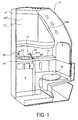
- an aircraft lavatory unit 2 that is installed in an aircraft is provided with a structural frame 6, inside which a lavatory 4 is compartmentalized.
- the lavatory 4 is provided with a hand wash basin 10, a toilet 12, a counter 14, a storage shelf 16, two sheets of mirrors 18A and 18B that open and close the storage shelf 16, and the like.
- the hand wash basin 10 is provided with a sink 20, a sink bowl 22 that is provided in the sink 20, a faucet main body 24 (a faucet) that is vertically arranged in the sink 20, and a soap water supply nozzle 26 that is vertically arranged in the sink 20.
- a faucet device 30A supplies water and hot water to the faucet main body 24.
- the faucet device 30A is configured by including a water supply channel 32, a hand sensor 34A, a water passage sensor 34B, a temperature sensor 34C, an overheating sensor 34D, a temperature fuse 35, a water temperature adjustment dial 36, a valve module 38, a heater module 40, and a controller module 42.
- the water supply channel 32 connects a water supply pipe 46, which is connected to a water supply tank 44 via a pipe 45, and the faucet main body 24.
- the hand sensor 34A is provided in the faucet main body 24 or in a section of the sink 20 which is located near the faucet main body 24.
- the hand sensor 34A detects whether a hand is inserted below the faucet main body 24 and outputs the detection result to control means 68 that will be described later.
- various conventionally known sensors can be used, such as an infrared sensor that irradiates an infrared light and detects reflected light that is reflected by the hand, or the like.
- the water passage sensor 34B detects whether or not water is flowing in the water supply channel 32 and outputs the detection result to the control means 68.
- the temperature sensor 34C detects a temperature of the water flowing in the water supply channel 32 on the downstream side of the heater module 40, outputs the detection result to the control means 68, and then causes the control means 68 to perform a feedback control of the water temperature.
- downstream indicates a direction from the water supply tank 44 to the faucet main body 24 in the water supply channel 32 that connects the faucet main body 24 and the water supply tank 44.
- the overheating sensor 34D detects whether heating means 58, which will be described later, of the heating module 40 has overheated and the temperature of the water flowing in the water supply channel 32 on the downstream side of the heating module 40 has reached a predetermined upper limit temperature, and outputs the detection result to the control means 68.
- the control means 68 obtains the detection result from the overheating sensor 34D that indicates that the water temperature has reached the upper limit temperature, the control means 68 cuts off the power supply to the heating means 58.
- a phenomenon in which the water temperature goes up abnormally and reaches the upper limit temperature in this manner may be caused by suspension of the water supply as well as a failure of the heating module 40.
- thermosensor 34C may be used as the temperature sensor 34C and the overheating sensor 34D.
- a thermistor can be used as the temperature sensor 34C, and a thermostat can be used as the overheating sensor 34D, for example.
- installation locations of the water passage sensor 34B, the temperature sensor 34C, and the overheating sensor 34D are not limited.
- the temperature fuse 35 forcibly cuts off the power supply with respect to the heating means 58 by fusing when the heating means 58, which will be described later, of the heating module 40 has overheated.
- the water temperature adjustment dial 36 is provided in the faucet main body 24 or in a section of the sink 20 which is located near the faucet main body 24.
- the water temperature adjustment dial 36 is rotationally operated to generate an operational signal for performing the adjustment of the water temperature and outputs the signal to the control means 68 that will be described later.
- various conventionally known operating units such as a selector switch, a selector button, or a touch panel, may be provided, the operating unit generating an operational signal for switching water and hot water and outputting the signal to the control means 68 that will be described later.
- valve module 38 and the heater module 40 are disposed in series in a section of the water supply channel 32.
- the valve module 38 is configured by including a first joint 50A that is removably joined to the water supply channel 32, a second joint 50B, a water supply valve 48 (an electromagnetic valve) that connects a section between the first joint 50A and the second joint 50B, a third connector 52C, and a first case 54A.
- the water supply valve 48 is stored in the first case 54A having a rectangular box-shape, and the opening and closing operation thereof is controlled by a first control signal from the control means 68 that will be described later.
- the first joint 50A is provided so as to protrude from a first outer surface 5402 of the first case 54A.
- the first joint 50A is connected to an opening 4802 on the upstream side of the water supply valve 48 and is removably joined to a water supply pipe 46 that is a section of the water supply channel 32 located further to the upstream side than the water supply valve 48.
- upstream indicates a direction from the faucet main body 24 to the water supply tank 44 in the water supply channel 32 that connects the faucet main body 24 and the water supply tank 44.
- the second joint 50B is a female joint.
- the second joint 50B is provided so as to form a concave shape in a second outer surface 5404 of the first case 54A, the second surface 5404 facing the first outer surface 5402.
- the second joint 50B is connected to an opening 4804 on the downstream side of the water supply valve 48.
- a portion of the water supply channel 32 is configured by the first joint 50A, the water supply valve 48, and the second joint 50B.
- the third connector 53C is removably joined to a first connector 52A of the controller module 42, which will be described later, and outputs to the water supply valve 48 the first control signal that is output from the control means 68 via the first connector 52A.
- the first case 54A is formed of a metal material or a synthetic resin material, but, from a viewpoint of achieving weight reduction, it is preferable that the first case 54A be formed of a light-weight synthetic resin material.
- screw holes 67 are formed respectively on both sides of the second joint 50B so as to be positioned in parallel with a center axis of the second joint 50B.
- the heater module 40 is configured by including a third joint 50C that can be attached to and removed from the second joint 50B, a fourth joint 50D that is removably joined to the water supply channel 32, a heating pipeline (a water channel for heating) 60 that connects a section between the joint 50C and the joint 50D, the heating means 58, a fourth connector 52D, and a second case 54B.
- a heating pipeline a water channel for heating
- the heating means 58 and the heating pipeline 60 are stored in the second case 54B having a rectangular box-shape.
- the heating means 58 heats water flowing in the heating pipeline 60, namely, the water channel for heating.
- the heating means 58 is configured by an electric heater.
- the electric heater may be provided outside the heating pipeline 60 or inside the heating pipeline 60.
- a water heating operation of the electric heater is controlled by a second control signal output from the control means 68.
- control method of the electric power (electric current) supplied to the electric heater by the second control signal various conventionally known control methods can be used that include a method of controlling a phase angle of an alternating current, a method of pulse-controlling the alternating current by switching, a method of controlling the magnitude of a direct current, a method of pulse-controlling the direct current, and the like.
- the heating means 58 is not limited to the electric heater, and as the heating means 58, various conventionally known heating means 58 can be used that include a device that is configured by an electromagnetic coil and a heating element that generates heat using electromagnetic waves from the electromagnetic coil, and the like.
- the third joint 50C is provided so as to protrude from a first outer surface 5410 of the second case 54B.
- the third joint 50C is connected to an upstream end 6002 of the heating pipeline 60 and is configured so as to be removably joined to the second joint 50B.
- the third joint 50C is a male joint, and the reference numeral 62 in the drawing indicates an O-ring that is fitted into an outer peripheral groove of the third joint 50C.
- the fourth joint 50D is provided so as to protrude from a second outer surface 5412 of the second case 54B, the second outer surface 5412 facing the first outer surface 5410.
- the fourth joint 50D is provided at a downstream end 6004 of the heating pipeline 60 and is configured so as to be removably joined, via a pipe 64, to the faucet main body 24 that is a section of the water supply channel 32, the section being located further to the downstream side than the heating means 58. Therefore, a part of the water supply channel 32 is configured by the third joint 50C, the heating pipeline 60, and the fourth joint 50D.
- the fourth connector 52D is removably joined to a second connector 52B of the controller module 42, which will be described later, and outputs to the heating means 58 the second control signal that is output from the control means 68 via the second connector 52B.
- the second case 54B is also formed of a metal material or a synthetic resin material, but, from a viewpoint of achieving the weight reduction, it is preferable that the second case 54B be formed of a lightweight synthetic resin material.
- the second outer surface 5404 which is a portion of the first case 54A in which the second joint 50B is provided
- the first outer surface 5410 which is a portion of the second case 54B in which the third joint 50c is provided
- screw through holes 56 are formed in the second case 54B at positions corresponding to each of the screw holes 67.
- the first case 54A and the second case 54B are configured so as to be fastened, in a direction that causes the second outer surface 5404 and the first outer surface 5410 to abut against each other, via screw members 66 that are inserted into the screw through holes 56 so as to be screwed into the screw holes 67.
- the controller module 42 is configured by including the control means 68, the first connector 52A, the second connector 52B, and a third case 54C.
- the control means 68 is stored in the third case 54C having a rectangular box-shape.
- the control means 68 controls the opening and closing operation of the water supply valve 48 based on the detection result of the hand sensor 34A, and controls the heating operation of the heating means 58 based on the operational signal of the water temperature adjustment dial 36.
- the temperature of the water discharged from the faucet main body 24 is controlled by the detection operation of the water passage sensor 34B, the detection operation of the temperature sensor 34C, the detection operation of the overheating sensor 34D, and the presence/absence of the fusing of the temperature fuse 35.
- control means 68 when conditions are satisfied, namely, when a hand is detected by the hand sensor 34A and a passage of water is detected by the water passage sensor 34B, the control means 68 performs a feedback control of the heating operation of the heating means 58 so that the water temperature detected by the temperature sensor 34C becomes equal to a predetermined temperature.
- the control means 68 performs a control to stop the heating operation of the heating means 58 (a first-stage overheating prevention control) in order to inhibit the heating means 58 from overheating.
- a first-stage overheating prevention control a control to stop the heating operation of the heating means 58
- the control means is automatically restored to a normal temperature control (a feedback control) that controls the heating operation of the heating means 58 based on the operational signal of the water temperature adjustment dial 36 and the water temperature detected by the temperature sensor 34C.
- the heating operation of the heating means 58 is irreversibly stopped (a second-stage overheating prevention control) as a result of the electric power supply to the heating means 58 being cut off.
- the first connector 52A is formed so as to protrude from the outer surface of the third case 54C and is configured so as to be able to be attached to and removed from the third connector 52C.
- the first connector 52A outputs the first control signal to the water supply valve 48 via the third connector 52C.
- the second connector 52B is formed so as to protrude from the outer surface of the third case 54C and is configured so as to be able to be attached to and removed from the fourth connector 52D.
- the second connector 52B outputs the second control signal to the heating means 58 from the control means 68 via the fourth connector 52D.
- the third case 54C is also formed of a metal material or a synthetic resin material, but, from a viewpoint of achieving the weight reduction, it is preferable that the third case 54C be formed of a lightweight synthetic resin material.
- the second joint 50B and the third joint 50C are joined by inserting the third joint 50C of the heater module 40 into the second joint 50B of the valve module 38, and the screw members 66 are used to fasten together the first case 54A and the second case 54B.
- the valve module 38 and the heater module 40 are joined in series via the second joint 50B and the third joint 50C.
- the first connector 52A of the controller module 42 is joined to the third connector 52C of the valve module 38, and the second connector 52B of the controller module 42 is joined to the fourth connector 52D of the heater module 40.
- the first joint 50A of the valve module 38 is joined to the water supply pipe 46.
- the fourth joint 50D of the heater module 40 is joined to the faucet main body 24 via the pipe 64.
- the assembly of the faucet device 30A of the aircraft lavatory unit 2 is completed in the above-described manner, and it is advantageous for easily performing the assembly.
- valve module 38, the heater module 40, and the controller module 42 are stored and held in a casing that is not illustrated in the drawings, for example, and the casing is mounted in the structural frame 6 or the like.
- valve module 38 and the heater module 40 are directly joined to each other by the second joint 50B and the third joint 50C, it is possible to omit a pipe that has been conventionally necessary.
- control means 68 is removably joined to the water supply valve 48 via the first and third connectors 52A and 52C, and the control means 68 is removably joined to the heating means 58 via the second and fourth connectors 52B and 52D. Therefore, it is possible to omit a wiring member that outputs the first control signal from the control means 68 to the water supply valve 48 and a wiring member that outputs the second control signal from the control means 68 to the heating means 58.
- control means 68 fails, it is only necessary to replace the controller module 42, thereby keeping the costs to a minimum necessary level. Therefore, it becomes even more advantageous for achieving the weight reduction and the space-saving of the faucet device 30A.
- control means 68 instead of joining the control means 68, the water supply valve 48, and the heating means 58 via the connectors, they may be joined via the wiring members, but according to the present embodiment, it becomes advantageous for achieving the weight reduction and the space-saving.
- the second embodiment is a modified example of the first embodiment, differing from the first embodiment with respect to a joining structure between the valve module 38 and the heater module 40, but otherwise the same as the first embodiment.
- a faucet device 30B is provided with a holding member 55A that holds the first case 54A and the second case 54B.
- the first case 54A and the second case 54B are held by the holding member 55A by being separately mounted on the holding member 55A via a screw member or a mounting fixture that is not illustrated in the drawings.
- the holding member 55A it is only necessary for the holding member 55A to hold the first case 54A and the second case 54B, and it is possible to use, as the holding member 55A, various conventionally known members, such as a cover that covers the first case 54A and the second case 54B, a frame that has an L-shaped cross-section, and the like.
- the third embodiment is a modified example of the first embodiment, differing from the first embodiment with respect to a joining structure of the second joint and the third joint, but otherwise the same as the first embodiment.
- a second joint 70 of the valve module 38 is formed so as to protrude from the second outer surface 5404 of the first case 54A, a flange portion 7002 that has a larger diameter than that of other portions of the second joint 70 is formed at a tip end of the second joint 70, and an O-ring 7004 is fitted into a groove formed in an outer periphery of the flange portion 7002.
- a third joint 72 of the heater module 40 has an identical shape to that of the second joint 70 and is formed so as to protrude from the first outer surface 5410 of the second case 54B.
- a flange portion 7202 that has a larger diameter than that of other portions of the third joint 72 is formed at a tip end of the third joint 72, and an O-ring 7204 is fitted into a groove formed in an outer periphery of the flange portion 7202.
- a holding member (a fastener) 74 is fitted with respect to the second joint 70 and the third joint 72, in a state in which axial centers thereof are aligned with each other and tip ends thereof abut against each other, so that the holding member 74 surrounds outer peripheries of the second joint 70 and the third joint 72.
- the flange portions 7002 and 7202 of the second joint 70 and the third joint 72 being sandwiched by the holding member 74, the second joint 70 is joined to the third joint 72, and further, a joining state of the joints 70 and 72 is held by the holding member 74.
- the second joint 70 and the third joint 72 are configured by including the holding member 74.
- the quick joint is a joint that is commercially available as a clamshell coupling, and the holding member 74 is called a clamp.
- the valve module 38 and the heater module 40 are disposed in this order from the upstream side toward the downstream side of the water flowing in the water supply channel 32, that order may be reversed and the heater module 40 and the valve module 38 may be disposed in this order from the upstream side toward the downstream side of the water flowing in the water supply channel 32.
- the fourth joint 50D of the heater module 40 is joined to the upstream side of the water supply channel 32
- the third joints 50C and 72 of the heater module 40 are joined to the second joints 50B and 70
- the first joint 50 of the valve module 38 is joined to the downstream side of the water supply channel 32.
- the fourth embodiment differs from the first embodiment in that the fourth embodiment is further provided with a water purification module 76 that is disposed in series with the valve module 38 and the heater module 40 in a section of the water supply channel 32.
- the water purification module 76 is provided with two joints, namely, fifth and sixth joints 50E and 50F that are removably joined to the water supply channel 32 or any one of the first to fourth joints 50A, 50B, 50C, and 50D, a water purification pipeline 78 (a water purification water channel) that connects a section between the joints 50E and 50F, water purification means 80, and a fourth case 54D.
- a water purification pipeline 78 a water purification water channel
- the water purification pipeline 78 and the water purification means 80 are stored in the fourth case 54D having a rectangular box-shape.
- the water purification means 80 is provided in the water purification pipeline 78 and purifies water flowing in the water purification pipeline 78.
- the water purification means 80 conventionally known devices using various materials can be used, such as activated carbon, a filter, or the like that is provided inside the water purification pipeline 78.
- the fifth joint 50E is provided so as to protrude from a first outer surface 5420 of the fourth case 54D, is connected to an upstream end 7802 of the water purification pipeline 78, and is removably joined to the water supply pipe 46 that is a section of the water supply channel 32, the section being located further to the upstream side than the water purification module 76.
- the sixth joint 50F is a female joint.
- the sixth joint 50F is provided so as to form a concave shape in a second outer surface 5422 of the fourth case 54D, the second outer surface 5422 facing the first outer surface 5420, and is configured to be connected to a downstream end 7804 of the water purification pipeline 78, and to be removably joined to the first joint 50A of the valve module 38.
- the first joint 50A is a male joint that can be joined to the sixth joint 50F.
- the reference numeral 88 in the drawing indicates an O-ring that is fitted into an outer peripheral groove of the first joint 50A. Therefore, a part of the water supply channel 32 is configured by the fifth joint 50E, the water purification pipeline 78, and the sixth joint 50F.
- the fourth case 54D is also formed of a metal material or a synthetic resin material, but, from a viewpoint of achieving the weight reduction, it is preferable that the fourth case 54D be formed of a light-weight synthetic resin material.
- screw through holes 82 are formed respectively on both sides of the sixth joint 50F so as to be positioned in parallel with a center axis of the sixth joint 50F.
- the first case 54A and the fourth case 54D are configured so as to be fastened, in a direction that causes the second outer surface 5422 and the first outer surface 5402 to abut against each other, via screw members 86 that are inserted into the screw through holes 82 so as to be screwed into the screw holes 84.
- An assembly of a faucet device 30D of the aircraft lavatory unit 2 according to the fourth embodiment is performed in a manner described below.
- the first joint 50A and the sixth joint 50F are joined by inserting the first joint 50A of the valve module 38 into the sixth joint 50F of the water purification module 76, and the screw members 86 are used to fasten together the first case 54A and the fourth case 54D.
- the valve module 38 and the water purification module 76 are joined in series via the first joint 50A and the sixth joint 50F.
- the second joint 50B of the valve module 38 and the third joint 50C of the heater module 40 are joined to each other, and the screw members 66 are used to fasten together the first case 54A and the second case 54B.
- the valve module 38 and the heater module 40 are joined in series via the second joint 50B and the third joint 50C.
- the first connector 52A of the controller module 42 is joined to the third connector 52C of the valve module 38, and the second connector 52B of the controller module 42 is joined to the fourth connector 52D of the heater module 40.
- the fifth joint 50E of the water purification module 76 is joined to the water supply pipe 46.
- the fourth joint 50D of the heater module 40 is joined to the faucet main body 24 via the pipe 64.
- the assembly of the faucet device 30D of the aircraft lavatory unit 2 is completed in the above-described manner, and it is advantageous for easily performing the assembly.
- the water purification module 76, the valve module 38, the heater module 40, and the controller module 42 are stored and held in a casing that is not illustrated in the drawings, for example, and the casing is mounted in the structural frame 6 or the like.
- valve module 38 and the water purification module 76 are directly joined to each other by the first joint 50A and the sixth joint 50F, it is possible to omit a pipe that causes the water purification means 80 and the water supply valve 48 to be joined to each other. Further, when any one of the water purification means 80, the water supply valve 48, and the heating means 58 fails, it is only necessary to replace any one of the water purification module 76, the valve module 38, and the heater module 40. Thereby, the replacement work is easily done while keeping the costs to a minimum necessary level.
- the fifth embodiment is a modified example of the fourth embodiment, differing from the fourth embodiment in that a joining structure between the water purification module 76, the valve module 38, and the heater module 40 is a similar to that of the second embodiment in which a holding member is used, but otherwise the same as the fourth embodiment.
- a faucet device 30E is provided with a holding member 55B that holds the fourth case 54D, the first case 54A, and the second case 54B.
- the first case 54A, the second case 54B, and the fourth case 50C are held by the holding member 55B by being separately mounted on the holding member 55B via a screw member or a mounting fixture that is not illustrated in the drawings. It is only necessary for the holding member 55B to hold the first case 54A, the second case 54B, and the fourth case 54D, and it is possible to use, as the holding member 55B, various conventionally known members, such as a cover that covers the first case 54A, the second case 54B, and the fourth case 54D, a frame that has a L-shaped cross-section, and the like.
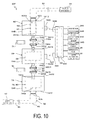
- a sixth embodiment is a modified example of the fourth embodiment, differing from the fourth embodiment in that a joining structure between the first joint and the sixth joint is provided via a holding member similar to the third embodiment, as well as the joining structure between the second joint and the third joint, but otherwise the same as the fourth embodiment.
- a first joint 90 of the valve module 38 is formed so as to protrude from the first outer surface 5402 of the first case 54A, a flange portion 9002 that has a larger diameter than that of other portions of the first joint 90 is formed at a tip end of the first joint 90, and an O-ring 9004 is fitted into a groove formed in an outer periphery of the flange portion 9002.
- the sixth joint 50F of the water purification module 76 has an identical shape to that of the first joint 90 and is formed so as to protrude from the second outer surface 5422 of the fourth case 54D.
- a flange portion 9202 that has a larger diameter than that of other portions of a sixth joint 92 is formed at a tip end of the sixth joint 92, and an O-ring 9204 is fitted into a groove formed in an outer periphery of the flange portion 9202.
- a holding member (a fastener) 94 is fitted with respect to the first joint 90 and the sixth joint 92, in a state in which axial centers thereof are aligned with each other and tip ends thereof abut against each other, so that the holding member 94 surrounds outer peripheries of the first joint 90 and the sixth joint 92.
- the present embodiment is configured by including the first joint 90, the sixth joint 92, and the holding member 94.
- the water purification module 76, the valve module 38, and the heater module 40 can be disposed in a desired order by causing the two fifth and sixth joints 50E and 50F of the water purification module 76 to be removably joined to the water supply channel 32 or any one of the first to fourth joints 50A, 50B, 50C, and 50D.
- male and female joining members that connect the first case 54A, the second case 54B, and the third case 54C are interchangeable.
Landscapes
- Engineering & Computer Science (AREA)
- Physics & Mathematics (AREA)
- Thermal Sciences (AREA)
- General Engineering & Computer Science (AREA)
- Mechanical Engineering (AREA)
- Combustion & Propulsion (AREA)
- Chemical & Material Sciences (AREA)
- Public Health (AREA)
- Water Supply & Treatment (AREA)
- Health & Medical Sciences (AREA)
- Hydrology & Water Resources (AREA)
- Life Sciences & Earth Sciences (AREA)
- Aviation & Aerospace Engineering (AREA)
- Fluid Mechanics (AREA)
- Domestic Plumbing Installations (AREA)
- Instantaneous Water Boilers, Portable Hot-Water Supply Apparatuses, And Control Of Portable Hot-Water Supply Apparatuses (AREA)
Abstract
Description
- The present invention relates to a faucet device for an aircraft lavatory unit.
- As a faucet device that is provided in an aircraft lavatory unit, a device is known in which a hot water supply line and a water supply line are connected to a water supply tap (a faucet) and a water temperature is adjusted by mixing the hot water and the water at the water tap.
- In
Patent Document 1, a device is disclosed in which the hot water supply line is omitted by providing a heating unit designed to heat water on a section of the water supply line that supplies water to the water supply tap. Further, in the faucet device, a water supply valve (an electromagnetic valve) is arranged in the water supply line. The water supply valve controls a discharge of the water from the water supply tap based on detection results of a hand sensor that is provided near the water supply tap. - Patent Document 1:
Japanese Unexamined Patent Application Publication No. 2003-106662A - In the above-described conventional technology, a section between the water supply tap and the heating unit and a section between the heating unit and the water supply valve are respectively joined by a pipe.
- As a result, in a faucet device of a conventional aircraft lavatory unit, weight of the pipes increases, and the pipes occupy a large space.
- Meanwhile, weight reduction is required for the aircraft lavatory unit from a viewpoint of fuel economy. Further, from a viewpoint of increasing the number of seats, space-saving is also required, and there is still a room for improvement with respect to the weight reduction and the space-saving of the faucet device. Further, in order to achieve the weight reduction and the space-saving of the faucet device, it can be considered to configure the heating unit and the water supply valve in an integrated manner. However, in this case, even when one of the heating unit and the water supply valve fails, the device as a whole has to be replaced, which causes a problem of increased cost.
- In light of the above-described situation, an object of the present invention is to provide a faucet device for an aircraft lavatory unit, the faucet device being advantageous in achieving weight reduction and space-saving and further in minimizing maintenance costs.
- In order to achieve the above-described object, a faucet device for an aircraft lavatory unit according to the present invention is provided with a water supply channel that connects a water supply pipe and a faucet main body, a water supply valve that is disposed in the water supply channel, heating means that heats water supplied from the water supply channel, and control means that perform a control of an opening and closing operation of the water supply valve and a heating operation of the heating means. The faucet device for the aircraft lavatory unit includes a valve module and a heater module that are disposed in series in a section of the water supply channel. The valve module is provided with a first case, a first joint that is provided in a surface of the first case and is removably joined to the water supply channel, a second joint that is provided in the surface of the first case at a different location from that of the first joint, and a water supply valve that is integrated in the first case and connects the first joint and the second joint. The heater module is provided with a second case, a third joint that is provided in a surface of the second case and is removably joined to the second joint, a fourth joint that is provided in the surface of the second case at a different location from that of the third joint and is removably joined to the water supply channel, a water channel for heating that is integrated in the second case and connects the third joint and the fourth joint, and the heating means that is integrated in the second case and heats water flowing in the water channel for heating.
- According to the present invention, as the valve module and the heater module are directly joined via the second joint and the third joint, it is possible to omit a pipe that has been conventionally necessary. Further, when the water supply valve or the heating means fails, it is only required to replace the valve module or the heater module, thereby keeping the costs to a minimum necessary level. Therefore, it becomes advantageous for achieving weight reduction and space-saving of a faucet device and minimizing maintenance costs thereof.
-
-
FIG. 1 is an explanatory view illustrating a configuration of an aircraft lavatory unit in which afaucet device 30A of an aircraft lavatory unit according to a first embodiment is adopted. -
FIG. 2 is an exploded view illustrating a configuration of thefaucet device 30A of the aircraft lavatory unit according to the first embodiment. -
FIG. 3 is an assembly view of thefaucet device 30A of the aircraft lavatory unit according to the first embodiment. -
FIG. 4 is an assembly view illustrating main parts of afaucet device 30B of an aircraft lavatory unit according to a second embodiment. -
FIG. 5 is an exploded view illustrating a configuration of afaucet device 30C of an aircraft lavatory unit according to a third embodiment. -
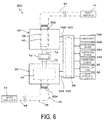
FIG. 6 is an assembly view of thefaucet device 30C of the aircraft lavatory unit according to the third embodiment. -
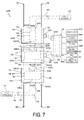
FIG. 7 is an exploded view illustrating a configuration of afaucet device 30D of an aircraft lavatory unit according to a fourth embodiment. -
FIG. 8 is an assembly view of thefaucet device 30D of the aircraft lavatory unit according to the fourth embodiment. -
FIG. 9 is an assembly view illustrating main parts of afaucet device 30E of an aircraft lavatory unit according to a fifth embodiment. -
FIG. 10 is an exploded view illustrating a configuration of afaucet device 30F of an aircraft lavatory unit according to a sixth embodiment. -
FIG. 11 is an assembly view of thefaucet device 30F of the aircraft lavatory unit according to the sixth embodiment. - Next, a first embodiment will be described with reference to the attached drawings.
- As illustrated in
FIG. 1 , anaircraft lavatory unit 2 that is installed in an aircraft is provided with astructural frame 6, inside which alavatory 4 is compartmentalized. - The
lavatory 4 is provided with ahand wash basin 10, atoilet 12, acounter 14, astorage shelf 16, two sheets ofmirrors storage shelf 16, and the like. - The
hand wash basin 10 is provided with asink 20, asink bowl 22 that is provided in thesink 20, a faucet main body 24 (a faucet) that is vertically arranged in thesink 20, and a soapwater supply nozzle 26 that is vertically arranged in thesink 20. - As illustrated in
FIG. 2 , afaucet device 30A supplies water and hot water to the faucetmain body 24. - The
faucet device 30A is configured by including awater supply channel 32, ahand sensor 34A, awater passage sensor 34B, atemperature sensor 34C, anoverheating sensor 34D, atemperature fuse 35, a watertemperature adjustment dial 36, avalve module 38, aheater module 40, and acontroller module 42. - The
water supply channel 32 connects awater supply pipe 46, which is connected to awater supply tank 44 via apipe 45, and the faucetmain body 24. - As illustrated in
FIG. 1 , thehand sensor 34A is provided in the faucetmain body 24 or in a section of thesink 20 which is located near the faucetmain body 24. Thehand sensor 34A detects whether a hand is inserted below the faucetmain body 24 and outputs the detection result tocontrol means 68 that will be described later. - As the
hand sensor 34A, various conventionally known sensors can be used, such as an infrared sensor that irradiates an infrared light and detects reflected light that is reflected by the hand, or the like. - The
water passage sensor 34B detects whether or not water is flowing in thewater supply channel 32 and outputs the detection result to the control means 68. - The
temperature sensor 34C detects a temperature of the water flowing in thewater supply channel 32 on the downstream side of theheater module 40, outputs the detection result to the control means 68, and then causes the control means 68 to perform a feedback control of the water temperature. Note that downstream indicates a direction from thewater supply tank 44 to the faucetmain body 24 in thewater supply channel 32 that connects the faucetmain body 24 and thewater supply tank 44. - The
overheating sensor 34D detects whether heating means 58, which will be described later, of theheating module 40 has overheated and the temperature of the water flowing in thewater supply channel 32 on the downstream side of theheating module 40 has reached a predetermined upper limit temperature, and outputs the detection result to the control means 68. When the control means 68 obtains the detection result from theoverheating sensor 34D that indicates that the water temperature has reached the upper limit temperature, the control means 68 cuts off the power supply to the heating means 58. A phenomenon in which the water temperature goes up abnormally and reaches the upper limit temperature in this manner may be caused by suspension of the water supply as well as a failure of theheating module 40. - Note that one sensor may be used as the
temperature sensor 34C and theoverheating sensor 34D. - Further, a thermistor can be used as the
temperature sensor 34C, and a thermostat can be used as theoverheating sensor 34D, for example. - Further, installation locations of the
water passage sensor 34B, thetemperature sensor 34C, and theoverheating sensor 34D are not limited. - The temperature fuse 35 forcibly cuts off the power supply with respect to the heating means 58 by fusing when the heating means 58, which will be described later, of the
heating module 40 has overheated. - As illustrated in
FIG. 1 , the watertemperature adjustment dial 36 is provided in the faucetmain body 24 or in a section of thesink 20 which is located near the faucetmain body 24. The watertemperature adjustment dial 36 is rotationally operated to generate an operational signal for performing the adjustment of the water temperature and outputs the signal to the control means 68 that will be described later. - Instead of the water
temperature adjustment dial 36, various conventionally known operating units, such as a selector switch, a selector button, or a touch panel, may be provided, the operating unit generating an operational signal for switching water and hot water and outputting the signal to the control means 68 that will be described later. - As illustrated in
FIG. 2 , thevalve module 38 and theheater module 40 are disposed in series in a section of thewater supply channel 32. - The
valve module 38 is configured by including afirst joint 50A that is removably joined to thewater supply channel 32, asecond joint 50B, a water supply valve 48 (an electromagnetic valve) that connects a section between thefirst joint 50A and thesecond joint 50B, athird connector 52C, and afirst case 54A. - The
water supply valve 48 is stored in thefirst case 54A having a rectangular box-shape, and the opening and closing operation thereof is controlled by a first control signal from the control means 68 that will be described later. - The first joint 50A is provided so as to protrude from a first
outer surface 5402 of thefirst case 54A. The first joint 50A is connected to anopening 4802 on the upstream side of thewater supply valve 48 and is removably joined to awater supply pipe 46 that is a section of thewater supply channel 32 located further to the upstream side than thewater supply valve 48. Note that upstream indicates a direction from the faucetmain body 24 to thewater supply tank 44 in thewater supply channel 32 that connects the faucetmain body 24 and thewater supply tank 44. - The second joint 50B is a female joint. The second joint 50B is provided so as to form a concave shape in a second
outer surface 5404 of thefirst case 54A, thesecond surface 5404 facing the firstouter surface 5402. The second joint 50B is connected to anopening 4804 on the downstream side of thewater supply valve 48. - Therefore, a portion of the
water supply channel 32 is configured by the first joint 50A, thewater supply valve 48, and the second joint 50B. - The third connector 53C is removably joined to a
first connector 52A of thecontroller module 42, which will be described later, and outputs to thewater supply valve 48 the first control signal that is output from the control means 68 via thefirst connector 52A. - The
first case 54A is formed of a metal material or a synthetic resin material, but, from a viewpoint of achieving weight reduction, it is preferable that thefirst case 54A be formed of a light-weight synthetic resin material. - In the second
outer surface 5404, screw holes 67 are formed respectively on both sides of the second joint 50B so as to be positioned in parallel with a center axis of the second joint 50B. - The
heater module 40 is configured by including a third joint 50C that can be attached to and removed from the second joint 50B, a fourth joint 50D that is removably joined to thewater supply channel 32, a heating pipeline (a water channel for heating) 60 that connects a section between the joint 50C and the joint 50D, the heating means 58, afourth connector 52D, and asecond case 54B. - The heating means 58 and the
heating pipeline 60 are stored in thesecond case 54B having a rectangular box-shape. - The heating means 58 heats water flowing in the
heating pipeline 60, namely, the water channel for heating. - In the present embodiment, the heating means 58 is configured by an electric heater.
- The electric heater may be provided outside the
heating pipeline 60 or inside theheating pipeline 60. - A water heating operation of the electric heater is controlled by a second control signal output from the control means 68.
- More specifically, when the electric power supplied to the electric heater per unit time is zero, the heating value of the electric heater per unit time becomes zero, and the water heating is not performed. Further, when the electric power supplied to the electric heater per unit time becomes larger, the heating value of the electric heater per unit time becomes greater, and the water temperature becomes high. Note that, as a control method of the electric power (electric current) supplied to the electric heater by the second control signal, various conventionally known control methods can be used that include a method of controlling a phase angle of an alternating current, a method of pulse-controlling the alternating current by switching, a method of controlling the magnitude of a direct current, a method of pulse-controlling the direct current, and the like. Note that the heating means 58 is not limited to the electric heater, and as the heating means 58, various conventionally known heating means 58 can be used that include a device that is configured by an electromagnetic coil and a heating element that generates heat using electromagnetic waves from the electromagnetic coil, and the like.
- The third joint 50C is provided so as to protrude from a first
outer surface 5410 of thesecond case 54B. - The third joint 50C is connected to an
upstream end 6002 of theheating pipeline 60 and is configured so as to be removably joined to the second joint 50B. The third joint 50C is a male joint, and thereference numeral 62 in the drawing indicates an O-ring that is fitted into an outer peripheral groove of the third joint 50C. - The fourth joint 50D is provided so as to protrude from a second
outer surface 5412 of thesecond case 54B, the secondouter surface 5412 facing the firstouter surface 5410. - The fourth joint 50D is provided at a
downstream end 6004 of theheating pipeline 60 and is configured so as to be removably joined, via apipe 64, to the faucetmain body 24 that is a section of thewater supply channel 32, the section being located further to the downstream side than the heating means 58. Therefore, a part of thewater supply channel 32 is configured by the third joint 50C, theheating pipeline 60, and the fourth joint 50D. - The
fourth connector 52D is removably joined to asecond connector 52B of thecontroller module 42, which will be described later, and outputs to the heating means 58 the second control signal that is output from the control means 68 via thesecond connector 52B. - Similarly to the
first case 54A, thesecond case 54B is also formed of a metal material or a synthetic resin material, but, from a viewpoint of achieving the weight reduction, it is preferable that thesecond case 54B be formed of a lightweight synthetic resin material. - In a state in which the
valve module 38 and theheater module 40 are joined in series via the second joint 50B and the third joint 50C, the secondouter surface 5404, which is a portion of thefirst case 54A in which the second joint 50B is provided, and the firstouter surface 5410, which is a portion of thesecond case 54B in which the third joint 50c is provided, abut against each other. In a state in which the secondouter surface 5404 and the firstouter surface 5410 abut against each other in this manner, screw throughholes 56 are formed in thesecond case 54B at positions corresponding to each of the screw holes 67. - Therefore, in a state in which the
valve module 38 and theheater module 40 are joined in series via the second joint 50B and the third joint 50C, thefirst case 54A and thesecond case 54B are configured so as to be fastened, in a direction that causes the secondouter surface 5404 and the firstouter surface 5410 to abut against each other, viascrew members 66 that are inserted into the screw throughholes 56 so as to be screwed into the screw holes 67. - The
controller module 42 is configured by including the control means 68, thefirst connector 52A, thesecond connector 52B, and athird case 54C. - The control means 68 is stored in the
third case 54C having a rectangular box-shape. - The control means 68 controls the opening and closing operation of the
water supply valve 48 based on the detection result of thehand sensor 34A, and controls the heating operation of the heating means 58 based on the operational signal of the watertemperature adjustment dial 36. - Further, the temperature of the water discharged from the faucet
main body 24 is controlled by the detection operation of thewater passage sensor 34B, the detection operation of thetemperature sensor 34C, the detection operation of theoverheating sensor 34D, and the presence/absence of the fusing of thetemperature fuse 35. - More specifically, when conditions are satisfied, namely, when a hand is detected by the
hand sensor 34A and a passage of water is detected by thewater passage sensor 34B, the control means 68 performs a feedback control of the heating operation of the heating means 58 so that the water temperature detected by thetemperature sensor 34C becomes equal to a predetermined temperature. - Further, when the water temperature detected by the
overheating sensor 34D exceeds the upper limit temperature, the control means 68 performs a control to stop the heating operation of the heating means 58 (a first-stage overheating prevention control) in order to inhibit the heating means 58 from overheating. Note that, when the water temperature detected by theoverheating sensor 34D is lower than the upper limit temperature, the control means is automatically restored to a normal temperature control (a feedback control) that controls the heating operation of the heating means 58 based on the operational signal of the watertemperature adjustment dial 36 and the water temperature detected by thetemperature sensor 34C. - Further, when the
temperature fuse 35 has fused, the heating operation of the heating means 58 is irreversibly stopped (a second-stage overheating prevention control) as a result of the electric power supply to the heating means 58 being cut off. - The
first connector 52A is formed so as to protrude from the outer surface of thethird case 54C and is configured so as to be able to be attached to and removed from thethird connector 52C. Thefirst connector 52A outputs the first control signal to thewater supply valve 48 via thethird connector 52C. - The
second connector 52B is formed so as to protrude from the outer surface of thethird case 54C and is configured so as to be able to be attached to and removed from thefourth connector 52D. Thesecond connector 52B outputs the second control signal to the heating means 58 from the control means 68 via thefourth connector 52D. - Similarly to the
first case 54A, thethird case 54C is also formed of a metal material or a synthetic resin material, but, from a viewpoint of achieving the weight reduction, it is preferable that thethird case 54C be formed of a lightweight synthetic resin material. - An assembly of the
faucet device 30A of theaircraft lavatory unit 2 is performed in a manner described below. - The second joint 50B and the third joint 50C are joined by inserting the third joint 50C of the
heater module 40 into the second joint 50B of thevalve module 38, and thescrew members 66 are used to fasten together thefirst case 54A and thesecond case 54B. As a result, thevalve module 38 and theheater module 40 are joined in series via the second joint 50B and the third joint 50C. - Next, the
first connector 52A of thecontroller module 42 is joined to thethird connector 52C of thevalve module 38, and thesecond connector 52B of thecontroller module 42 is joined to thefourth connector 52D of theheater module 40. - The first joint 50A of the
valve module 38 is joined to thewater supply pipe 46. The fourth joint 50D of theheater module 40 is joined to the faucetmain body 24 via thepipe 64. - As illustrated in
FIG. 3 , the assembly of thefaucet device 30A of theaircraft lavatory unit 2 is completed in the above-described manner, and it is advantageous for easily performing the assembly. - Note that, after the assembly, the
valve module 38, theheater module 40, and thecontroller module 42 are stored and held in a casing that is not illustrated in the drawings, for example, and the casing is mounted in thestructural frame 6 or the like. - According to the present embodiment, as the
valve module 38 and theheater module 40 are directly joined to each other by the second joint 50B and the third joint 50C, it is possible to omit a pipe that has been conventionally necessary. - Further, when the
water supply valve 48 or the heating means 58 fails, it is only necessary to replace thevalve module 38 or theheater module 40. Thereby, the replacement work is easily done while keeping costs to a minimum necessary level. - Therefore, it becomes advantageous for minimizing maintenance costs as well as achieving weight reduction and space-saving of the
faucet device 30A. - Further, in the present embodiment, the control means 68 is removably joined to the
water supply valve 48 via the first andthird connectors fourth connectors water supply valve 48 and a wiring member that outputs the second control signal from the control means 68 to the heating means 58. - Further, when the control means 68 fails, it is only necessary to replace the
controller module 42, thereby keeping the costs to a minimum necessary level. Therefore, it becomes even more advantageous for achieving the weight reduction and the space-saving of thefaucet device 30A. - Note that, instead of joining the control means 68, the
water supply valve 48, and the heating means 58 via the connectors, they may be joined via the wiring members, but according to the present embodiment, it becomes advantageous for achieving the weight reduction and the space-saving. - Next, a second embodiment will be described.
- The second embodiment is a modified example of the first embodiment, differing from the first embodiment with respect to a joining structure between the
valve module 38 and theheater module 40, but otherwise the same as the first embodiment. - Note that in the embodiments described below, elements and members identical or similar to those of the first embodiment are assigned identical reference numerals, and descriptions thereof are omitted or described simply, while different elements from the first embodiment are mainly described.
- As illustrated in
FIG. 4 , in a state in which thevalve module 38 and theheater module 40 are joined in series via the second joint 50B and the third joint 50C, afaucet device 30B is provided with a holdingmember 55A that holds thefirst case 54A and thesecond case 54B. - The
first case 54A and thesecond case 54B are held by the holdingmember 55A by being separately mounted on the holdingmember 55A via a screw member or a mounting fixture that is not illustrated in the drawings. - It is only necessary for the holding
member 55A to hold thefirst case 54A and thesecond case 54B, and it is possible to use, as the holdingmember 55A, various conventionally known members, such as a cover that covers thefirst case 54A and thesecond case 54B, a frame that has an L-shaped cross-section, and the like. - Next, a third embodiment will be described.
- The third embodiment is a modified example of the first embodiment, differing from the first embodiment with respect to a joining structure of the second joint and the third joint, but otherwise the same as the first embodiment.
- As illustrated in
FIG. 5 andFIG. 6 , in afaucet device 30C of the third embodiment, a second joint 70 of thevalve module 38 is formed so as to protrude from the secondouter surface 5404 of thefirst case 54A, aflange portion 7002 that has a larger diameter than that of other portions of the second joint 70 is formed at a tip end of the second joint 70, and an O-ring 7004 is fitted into a groove formed in an outer periphery of theflange portion 7002. - A third joint 72 of the
heater module 40 has an identical shape to that of the second joint 70 and is formed so as to protrude from the firstouter surface 5410 of thesecond case 54B. Aflange portion 7202 that has a larger diameter than that of other portions of the third joint 72 is formed at a tip end of the third joint 72, and an O-ring 7204 is fitted into a groove formed in an outer periphery of theflange portion 7202. - A holding member (a fastener) 74 is fitted with respect to the second joint 70 and the third joint 72, in a state in which axial centers thereof are aligned with each other and tip ends thereof abut against each other, so that the holding
member 74 surrounds outer peripheries of the second joint 70 and the third joint 72. As a result of theflange portions member 74, the second joint 70 is joined to the third joint 72, and further, a joining state of thejoints member 74. - Therefore, in the present embodiment, the second joint 70 and the third joint 72 are configured by including the holding
member 74. - As this type of combination of the second joint 70, the third joint 72, and the holding
member 74, it is possible to use a commercially available quick joint (a quick release joint). - Note that in the present embodiment, the quick joint is a joint that is commercially available as a clamshell coupling, and the holding
member 74 is called a clamp. - According to the third embodiment described above, a similar effect to that of the first embodiment is achieved, and further, it is more advantageous for performing easy attachment and removal of the
valve module 38 to and from theheater module 40. - Note that in the first to third embodiments, although a case has been described in which the
valve module 38 and theheater module 40 are disposed in this order from the upstream side toward the downstream side of the water flowing in thewater supply channel 32, that order may be reversed and theheater module 40 and thevalve module 38 may be disposed in this order from the upstream side toward the downstream side of the water flowing in thewater supply channel 32. In this case, the fourth joint 50D of theheater module 40 is joined to the upstream side of thewater supply channel 32, thethird joints heater module 40 are joined to thesecond joints valve module 38 is joined to the downstream side of thewater supply channel 32. - Next, a fourth embodiment will be described.
- As illustrated in
FIG. 7 andFIG. 8 , the fourth embodiment differs from the first embodiment in that the fourth embodiment is further provided with awater purification module 76 that is disposed in series with thevalve module 38 and theheater module 40 in a section of thewater supply channel 32. - The
water purification module 76 is provided with two joints, namely, fifth andsixth joints water supply channel 32 or any one of the first tofourth joints joints fourth case 54D. - The water purification pipeline 78 and the water purification means 80 are stored in the
fourth case 54D having a rectangular box-shape. - The water purification means 80 is provided in the water purification pipeline 78 and purifies water flowing in the water purification pipeline 78. As the water purification means 80, conventionally known devices using various materials can be used, such as activated carbon, a filter, or the like that is provided inside the water purification pipeline 78.
- In the fourth embodiment, the fifth joint 50E is provided so as to protrude from a first
outer surface 5420 of thefourth case 54D, is connected to anupstream end 7802 of the water purification pipeline 78, and is removably joined to thewater supply pipe 46 that is a section of thewater supply channel 32, the section being located further to the upstream side than thewater purification module 76. - In the fourth embodiment, the sixth joint 50F is a female joint. The sixth joint 50F is provided so as to form a concave shape in a second
outer surface 5422 of thefourth case 54D, the secondouter surface 5422 facing the firstouter surface 5420, and is configured to be connected to adownstream end 7804 of the water purification pipeline 78, and to be removably joined to the first joint 50A of thevalve module 38. - Note that in the fourth embodiment, the first joint 50A is a male joint that can be joined to the sixth joint 50F. The
reference numeral 88 in the drawing indicates an O-ring that is fitted into an outer peripheral groove of the first joint 50A. Therefore, a part of thewater supply channel 32 is configured by the fifth joint 50E, the water purification pipeline 78, and the sixth joint 50F. - Similarly to the
first case 54A, thefourth case 54D is also formed of a metal material or a synthetic resin material, but, from a viewpoint of achieving the weight reduction, it is preferable that thefourth case 54D be formed of a light-weight synthetic resin material. - In the
fourth case 54D, screw throughholes 82 are formed respectively on both sides of the sixth joint 50F so as to be positioned in parallel with a center axis of the sixth joint 50F. - In a state in which the
valve module 38 and thewater purification module 76 are joined in series via the first joint 50A and the sixth joint 50F, the firstouter surface 5402 and the secondouter surface 5422 abut against each other. In a state in which the firstouter surface 5402 and the secondouter surface 5422 abut against each other in this manner, screw holes 84 are formed in thefirst case 54A at positions corresponding to each of the screw through holes 82. - In a state in which the
valve module 38 and thewater purification module 76 are joined in series via the first joint 50A and the sixth joint 50F, thefirst case 54A and thefourth case 54D are configured so as to be fastened, in a direction that causes the secondouter surface 5422 and the firstouter surface 5402 to abut against each other, viascrew members 86 that are inserted into the screw throughholes 82 so as to be screwed into the screw holes 84. - An assembly of a
faucet device 30D of theaircraft lavatory unit 2 according to the fourth embodiment is performed in a manner described below. The first joint 50A and the sixth joint 50F are joined by inserting the first joint 50A of thevalve module 38 into the sixth joint 50F of thewater purification module 76, and thescrew members 86 are used to fasten together thefirst case 54A and thefourth case 54D. As a result, thevalve module 38 and thewater purification module 76 are joined in series via the first joint 50A and the sixth joint 50F. - Next, the second joint 50B of the
valve module 38 and the third joint 50C of theheater module 40 are joined to each other, and thescrew members 66 are used to fasten together thefirst case 54A and thesecond case 54B. As a result, thevalve module 38 and theheater module 40 are joined in series via the second joint 50B and the third joint 50C. - Next, the
first connector 52A of thecontroller module 42 is joined to thethird connector 52C of thevalve module 38, and thesecond connector 52B of thecontroller module 42 is joined to thefourth connector 52D of theheater module 40. - The fifth joint 50E of the
water purification module 76 is joined to thewater supply pipe 46. - The fourth joint 50D of the
heater module 40 is joined to the faucetmain body 24 via thepipe 64. - The assembly of the
faucet device 30D of theaircraft lavatory unit 2 is completed in the above-described manner, and it is advantageous for easily performing the assembly. - Note that, after the assembly, the
water purification module 76, thevalve module 38, theheater module 40, and thecontroller module 42 are stored and held in a casing that is not illustrated in the drawings, for example, and the casing is mounted in thestructural frame 6 or the like. - According to the fourth embodiment, as the
valve module 38 and thewater purification module 76 are directly joined to each other by the first joint 50A and the sixth joint 50F, it is possible to omit a pipe that causes the water purification means 80 and thewater supply valve 48 to be joined to each other. Further, when any one of the water purification means 80, thewater supply valve 48, and the heating means 58 fails, it is only necessary to replace any one of thewater purification module 76, thevalve module 38, and theheater module 40. Thereby, the replacement work is easily done while keeping the costs to a minimum necessary level. - Therefore, it becomes advantageous for minimizing the maintenance costs as well as achieving the weight reduction and the space-saving.
- Further, similarly to the first embodiment, as it is possible to omit the wiring member from the control means 68 and it is only necessary to replace the
controller module 42 when the control means 68 fails, it becomes even more advantageous for achieving the weight reduction and the space-saving of thefaucet device 30D. - Next, a fifth embodiment will be described.
- The fifth embodiment is a modified example of the fourth embodiment, differing from the fourth embodiment in that a joining structure between the
water purification module 76, thevalve module 38, and theheater module 40 is a similar to that of the second embodiment in which a holding member is used, but otherwise the same as the fourth embodiment. - As illustrated in
FIG. 9 , in a state in which thewater purification module 76, thevalve module 38, and theheater module 40 are joined in series via the sixth joint 50F, the first joint 50A, the second joint 50B, and the third joint 50C, afaucet device 30E is provided with a holdingmember 55B that holds thefourth case 54D, thefirst case 54A, and thesecond case 54B. - The
first case 54A, thesecond case 54B, and thefourth case 50C are held by the holdingmember 55B by being separately mounted on the holdingmember 55B via a screw member or a mounting fixture that is not illustrated in the drawings. It is only necessary for the holdingmember 55B to hold thefirst case 54A, thesecond case 54B, and thefourth case 54D, and it is possible to use, as the holdingmember 55B, various conventionally known members, such as a cover that covers thefirst case 54A, thesecond case 54B, and thefourth case 54D, a frame that has a L-shaped cross-section, and the like. - A sixth embodiment is a modified example of the fourth embodiment, differing from the fourth embodiment in that a joining structure between the first joint and the sixth joint is provided via a holding member similar to the third embodiment, as well as the joining structure between the second joint and the third joint, but otherwise the same as the fourth embodiment.
- As illustrated in
FIG. 10 andFIG. 11 , a first joint 90 of thevalve module 38 is formed so as to protrude from the firstouter surface 5402 of thefirst case 54A, aflange portion 9002 that has a larger diameter than that of other portions of the first joint 90 is formed at a tip end of the first joint 90, and an O-ring 9004 is fitted into a groove formed in an outer periphery of theflange portion 9002. The sixth joint 50F of thewater purification module 76 has an identical shape to that of the first joint 90 and is formed so as to protrude from the secondouter surface 5422 of thefourth case 54D. Aflange portion 9202 that has a larger diameter than that of other portions of a sixth joint 92 is formed at a tip end of the sixth joint 92, and an O-ring 9204 is fitted into a groove formed in an outer periphery of theflange portion 9202. - Similarly to the third embodiment, a holding member (a fastener) 94 is fitted with respect to the first joint 90 and the sixth joint 92, in a state in which axial centers thereof are aligned with each other and tip ends thereof abut against each other, so that the holding
member 94 surrounds outer peripheries of the first joint 90 and the sixth joint 92. As a result of theflange portions member 94, the first joint 90 is joined to the sixth joint 92, and further, a joining state of thejoints member 94. Therefore, the present embodiment is configured by including the first joint 90, the sixth joint 92, and the holdingmember 94. - Even in the sixth embodiment described above, a similar effect to that of the fourth embodiment is achieved, and further, it is more advantageous for performing easy attachment and removal of the
water purification module 76, thevalve module 38, and theheater module 40 to and from one another. - Note that in the fourth to sixth embodiments, a case has been described in which the
water purification module 76, thevalve module 38, and theheater module 40 are disposed in this order from the upstream side toward the downstream side of the water flowing in thewater supply channel 32. - However, the
water purification module 76, thevalve module 38, and theheater module 40 can be disposed in a desired order by causing the two fifth andsixth joints water purification module 76 to be removably joined to thewater supply channel 32 or any one of the first tofourth joints - Further, it is needless to say that the male and female joining members that connect the
first case 54A, thesecond case 54B, and thethird case 54C are interchangeable. -
- 2
- Aircraft lavatory unit
- 24
- Faucet main body
- 30A, 30B, 30C, 30D, 30E, 30F
- Faucet device
- 32
- Water supply channel
- 38
- Valve module
- 40
- Heater module
- 42
- Controller module
- 46
- Water supply pipe
- 48
- Water supply valve
- 4802
- Upstream side opening
- 4804
- Downstream side opening
- 50A
- First joint
- 50B
- Second joint
- 50C
- Third joint
- 50D
- Fourth joint
- 52A
- First connector
- 52B
- Second connector
- 52C
- Third connector
- 52D
- Fourth connector
- 54A
- First case
- 54B
- Second case
- 54C
- Third case
- 54D
- Fourth case
- 55A, 55B
- Holding member
- 58
- Heating means
- 60
- Heating pipeline
- 6002
- Upstream end
- 6004
- Downstream end
- 68
- Control means
- 70
- Second joint
- 72
- Third joint
- 74
- Holding member
- 76
- Water purification module
- 78
- Water purification pipeline
- 80
- Water purification means
- 50E
- Fifth joint
- 50F
- Sixth joint
- 90
- First joint
- 92
- Sixth joint
- 94
- Holding member
Claims (9)
- A faucet device for an aircraft lavatory unit, comprising:a water supply channel that connects a water supply pipe and a faucet main body;a water supply valve disposed in the water supply channel;heating means for heating water supplied from the water supply channel;
andcontrol means for performing control of an opening and closing operation of the water supply valve and a heating operation of the heating means, the faucet device for the aircraft lavatory unit further comprising:a valve module and a heater module that are disposed in series in a section of the water supply channel,
the valve module including a first case, a first joint that is provided in a surface of the first case and is removably joined to the water supply channel, a second joint that is provided in the surface of the first case at a different location from that of the first joint, and a water supply valve that is integrated in the first case and connects the first joint and the second joint, and
the heater module including a second case, a third joint that is provided in a surface of the second case and is removably joined to the second joint, a fourth joint that is provided in the surface of the second case at a different location from that of the third joint and removably joined to the water supply channel, a water channel for heating that is integrated in the second case and connects the third joint and the fourth joint, and the heating means that is integrated in the second case and heats water flowing in the water channel for heating. - The faucet device for the aircraft lavatory unit according to claim 1, wherein
in a state in which the valve module and the heater module are joined in series via the second joint and the third joint, a portion of the first case in which the second joint is provided and a portion of the second case in which the third joint is provided abut against each other, and
screw members are provided that fasten the first case and the second case in a direction that causes the portions of the first and second cases to abut against each other. - The faucet device for the aircraft lavatory unit according to claim 1, wherein
in a state in which the valve module and the heater module are joined in series via the second joint and the third joint, a holding member is provided on which the first case and the second case are separately mounted and which holds the first case and the second case. - The faucet device for the aircraft lavatory unit according to claim 1, wherein the second joint and the third joint are removably joined and are configured by including a holding member that holds a state in which the second joint and the third joint are joined.
- The faucet device for the aircraft lavatory unit according to any one of claims 1 to 4, further comprising:a first connector that outputs a first control signal from the control means to the valve module; a second connector that outputs a second control signal from the control means to the heater module; anda controller module that is integrated into a third case, wherein
a third connector that is removably joined to the first connector is integrated into the first case, and
a fourth connector that is removably joined to the second connector is integrated into the second case. - The faucet device for the aircraft lavatory unit according to any one of claims 1 to 5, further comprising:a water purification module that is disposed in a section of the water supply channel and in series with the valve module and the heater module, wherein
the water purification module includes a fourth case, two fifth and sixth joints that are provided in a surface of the fourth case at different locations from each other and are removably joined to the water supply channel or any one of the first to fourth joints, a water purification water channel that is integrated into the fourth case and connects the fifth joint and sixth joint, and water purification means that is integrated into the fourth case and purifies water flowing in the water purification water channel. - The faucet device for the aircraft lavatory unit according to claim 6, wherein
in a state in which the valve module, the heater module, and the water purification module are joined in series via the joints, portions of the cases in which the joints are located abut against one another, the joints being joined together while joining adjacent modules, and
screw members are provided that fasten the cases in a direction that causes the portions of the cases to abut against one another. - The faucet device for the aircraft lavatory unit according to claim 6, wherein
in a state in which the valve module, the heater module, and the water purification module are joined in series via the joints, a holding member is provided on which the first case, the second case, and the fourth case are separately mounted and which holds the first case, the second case, and the fourth case. - The faucet device for the aircraft lavatory unit according to claim 6, wherein the joints that join the valve module, the heater module, and the water purification module are configured by including a holding member that causes the joints to be removably joined and holds a state in which the joints are joined.
Applications Claiming Priority (2)
| Application Number | Priority Date | Filing Date | Title |
|---|---|---|---|
| JP2013047509 | 2013-03-11 | ||
| PCT/JP2014/001368 WO2014141693A1 (en) | 2013-03-11 | 2014-03-11 | Faucet device for airplane lavatory unit |
Publications (3)
| Publication Number | Publication Date |
|---|---|
| EP2975333A1 true EP2975333A1 (en) | 2016-01-20 |
| EP2975333A4 EP2975333A4 (en) | 2017-01-04 |
| EP2975333B1 EP2975333B1 (en) | 2019-05-22 |
Family
ID=51536372
Family Applications (1)
| Application Number | Title | Priority Date | Filing Date |
|---|---|---|---|
| EP14762321.9A Active EP2975333B1 (en) | 2013-03-11 | 2014-03-11 | Faucet device for airplane lavatory unit |
Country Status (5)
| Country | Link |
|---|---|
| US (1) | US10365012B2 (en) |
| EP (1) | EP2975333B1 (en) |
| JP (1) | JP6439677B2 (en) |
| CN (1) | CN105008816B (en) |
| WO (1) | WO2014141693A1 (en) |
Families Citing this family (14)
| Publication number | Priority date | Publication date | Assignee | Title |
|---|---|---|---|---|
| JP6353033B2 (en) * | 2013-05-14 | 2018-07-04 | シーアンドディー ゾディアック,インコーポレイティド | Toilet portable water system |
| CN108166575A (en) * | 2016-08-28 | 2018-06-15 | 江辉军 | A kind of domestic intelligent is washed one's hands system |
| CN108252365A (en) * | 2016-08-28 | 2018-07-06 | 江雨涛 | A kind of automation washing equipment |
| CN108166574A (en) * | 2016-08-28 | 2018-06-15 | 江雨涛 | A kind of automation household washing equipment |
| CN108222135A (en) * | 2016-08-28 | 2018-06-29 | 江雨涛 | A kind of automation handwashing facilities |
| CN108252367A (en) * | 2016-08-28 | 2018-07-06 | 江辉军 | A kind of domestic intelligent handwashing facilities |
| CN106284531B (en) * | 2016-08-28 | 2018-07-27 | 温岭市智方科技有限公司 | Intelligent hand washing system |
| CN108204012A (en) * | 2016-08-28 | 2018-06-26 | 江雨涛 | A kind of home automation handwashing facilities |
| DE102017208804A1 (en) * | 2017-05-24 | 2018-11-29 | Airbus Operations Gmbh | Armature bracket with adapter element and vehicle wet cell and vehicle with a fitting holder |
| US11058260B2 (en) | 2017-08-28 | 2021-07-13 | The Yokohama Rubber Co., Ltd. | Lavatory unit for vehicle |
| US11098828B2 (en) * | 2018-12-07 | 2021-08-24 | The Boeing Company | Apparatus and methods for connecting a first electrically conductive tube and a second electrically conductive tube |
| JP6965960B2 (en) | 2020-04-15 | 2021-11-10 | 横浜ゴム株式会社 | Automatic faucet device |
| US20230210298A1 (en) * | 2021-12-30 | 2023-07-06 | Consuelo Neri | Portable Water Heater Assembly |
| CN114754193B (en) * | 2022-05-09 | 2023-12-19 | 广东圣玛洛热能科技有限公司 | Pull formula heating faucet of built-in height induction system |
Family Cites Families (13)
| Publication number | Priority date | Publication date | Assignee | Title |
|---|---|---|---|---|
| US6597256B2 (en) * | 2001-01-23 | 2003-07-22 | Adc Telecommunications, Inc. | Multi-circuit signal transformer |
| US6539173B2 (en) * | 2001-05-02 | 2003-03-25 | Dynamo Aviation, Inc. | Sensor controlled water heater and method of use |
| JP2003106662A (en) | 2001-09-28 | 2003-04-09 | Jamco Corp | Heating faucet |
| JP3835397B2 (en) * | 2002-11-14 | 2006-10-18 | 松下電器産業株式会社 | Water heater |
| JP3838191B2 (en) * | 2002-11-26 | 2006-10-25 | 松下電器産業株式会社 | Water heater |
| US7091456B2 (en) * | 2003-10-07 | 2006-08-15 | Goodrich Corporation | Aircraft hot water supply system |
| CN101366145B (en) * | 2006-01-06 | 2012-10-17 | 约翰逊控制技术公司 | Battery system with manifold for effluent release |
| JP2008175519A (en) * | 2006-12-22 | 2008-07-31 | Matsushita Electric Ind Co Ltd | Heat pump water heater |
| JP5104268B2 (en) | 2007-12-10 | 2012-12-19 | 横浜ゴム株式会社 | Restroom unit |
| DE102008047069A1 (en) * | 2008-09-12 | 2010-03-18 | Ksb Aktiengesellschaft | Device with a spout for a liquid |
| US9057183B2 (en) * | 2010-02-02 | 2015-06-16 | Chung-Chia Chen | Touch free automatic faucet |
| DE102011108884A1 (en) | 2011-07-28 | 2013-01-31 | Airbus Operations Gmbh | System for cable treatment |
| CN104018553A (en) * | 2014-06-27 | 2014-09-03 | 罗春春 | Water economizer for hot water supply pipe |
-
2014
- 2014-03-11 EP EP14762321.9A patent/EP2975333B1/en active Active
- 2014-03-11 CN CN201480013618.XA patent/CN105008816B/en not_active Expired - Fee Related
- 2014-03-11 US US14/775,579 patent/US10365012B2/en not_active Expired - Fee Related
- 2014-03-11 WO PCT/JP2014/001368 patent/WO2014141693A1/en not_active Ceased
- 2014-03-11 JP JP2015505293A patent/JP6439677B2/en not_active Expired - Fee Related
Also Published As
| Publication number | Publication date |
|---|---|
| EP2975333B1 (en) | 2019-05-22 |
| US10365012B2 (en) | 2019-07-30 |
| JPWO2014141693A1 (en) | 2017-02-16 |
| US20160018129A1 (en) | 2016-01-21 |
| CN105008816B (en) | 2019-03-08 |
| EP2975333A4 (en) | 2017-01-04 |
| CN105008816A (en) | 2015-10-28 |
| JP6439677B2 (en) | 2018-12-19 |
| WO2014141693A1 (en) | 2014-09-18 |
Similar Documents
| Publication | Publication Date | Title |
|---|---|---|
| US10365012B2 (en) | Faucet device for aircraft lavatory unit | |
| US9140466B2 (en) | Fluid heating system and instant fluid heating device | |
| EP3367004B1 (en) | Heat source device | |
| EP2554919B1 (en) | Modular water-saving device | |
| CN103562470B (en) | Including fitting housing and the sanitary fittings of control unit | |
| US11203857B2 (en) | Configurable faucet apparatus and methods of implementing and operating same | |
| ITMI20070936A1 (en) | SYSTEM AND MIXING GROUP FOR SANITARY SYSTEMS WITH ANI-LEGIONELLA DISINFECTION FUNCTION | |
| US10138620B2 (en) | Faucet assembly including a thermostatic mixing cartridge | |
| AU2021105325A4 (en) | End point instant heating/cooling system and method of providing instant heated/cooled fluid to an end point | |
| US20180372343A1 (en) | Water heating system including multi-function heat source apparatus | |
| CN103335132A (en) | Cold and hot water faucet and cold and hot water supply system | |
| US20090191500A1 (en) | Energy saving stove water heater | |
| EP3665410B1 (en) | Electronically controllable valve cartridge and mixing valve assembly | |
| JP3867771B2 (en) | Water heater | |
| US20130106097A1 (en) | Structure for fastening outlet module of water purifier | |
| GB2535258A (en) | Satellite for central heating or for teleheating with multifunction presettings | |
| JP2005172354A (en) | Module structure of electric instantaneous water heater | |
| JP4157876B2 (en) | Mist sauna combined water heater | |
| JP4476840B2 (en) | Hot water mixing unit and hot water supply system equipped with the same | |
| JP2006234241A (en) | Hot-water feed system | |
| WO2017111739A1 (en) | System capable of supplying energy to bathroom products requiring electrical energy | |
| JP2007003059A (en) | Hot water supply device | |
| JP2016183831A (en) | Water heater | |
| JP2007003165A (en) | Instantaneous water heater unit | |
| JP3809886B2 (en) | Bath device with water heater |
Legal Events
| Date | Code | Title | Description |
|---|---|---|---|
| PUAI | Public reference made under article 153(3) epc to a published international application that has entered the european phase |
Free format text: ORIGINAL CODE: 0009012 |
|
| 17P | Request for examination filed |
Effective date: 20151009 |
|
| AK | Designated contracting states |
Kind code of ref document: A1 Designated state(s): AL AT BE BG CH CY CZ DE DK EE ES FI FR GB GR HR HU IE IS IT LI LT LU LV MC MK MT NL NO PL PT RO RS SE SI SK SM TR |
|
| AX | Request for extension of the european patent |
Extension state: BA ME |
|
| DAX | Request for extension of the european patent (deleted) | ||
| A4 | Supplementary search report drawn up and despatched |
Effective date: 20161201 |
|
| RIC1 | Information provided on ipc code assigned before grant |
Ipc: E03C 1/02 20060101ALI20161125BHEP Ipc: F24H 9/14 20060101ALI20161125BHEP Ipc: H05B 3/40 20060101ALI20161125BHEP Ipc: B64D 11/02 20060101ALI20161125BHEP Ipc: F24H 9/00 20060101ALI20161125BHEP Ipc: E03C 1/044 20060101ALI20161125BHEP Ipc: F24H 1/10 20060101AFI20161125BHEP Ipc: F24H 9/20 20060101ALI20161125BHEP Ipc: F24D 17/00 20060101ALI20161125BHEP |
|
| GRAP | Despatch of communication of intention to grant a patent |
Free format text: ORIGINAL CODE: EPIDOSNIGR1 |
|
| STAA | Information on the status of an ep patent application or granted ep patent |
Free format text: STATUS: GRANT OF PATENT IS INTENDED |
|
| RIC1 | Information provided on ipc code assigned before grant |
Ipc: B64D 11/02 20060101ALI20181108BHEP Ipc: F24D 17/00 20060101ALI20181108BHEP Ipc: H05B 3/40 20060101ALI20181108BHEP Ipc: F24H 9/14 20060101ALI20181108BHEP Ipc: F24H 1/10 20060101AFI20181108BHEP Ipc: E03C 1/02 20060101ALI20181108BHEP Ipc: F24H 9/00 20060101ALI20181108BHEP Ipc: F24H 9/20 20060101ALI20181108BHEP Ipc: E03C 1/044 20060101ALI20181108BHEP |
|
| INTG | Intention to grant announced |
Effective date: 20181204 |
|
| RIN1 | Information on inventor provided before grant (corrected) |
Inventor name: KOYAMA, TAKASHI |
|
| GRAS | Grant fee paid |
Free format text: ORIGINAL CODE: EPIDOSNIGR3 |
|
| GRAA | (expected) grant |
Free format text: ORIGINAL CODE: 0009210 |
|
| STAA | Information on the status of an ep patent application or granted ep patent |
Free format text: STATUS: THE PATENT HAS BEEN GRANTED |
|
| AK | Designated contracting states |
Kind code of ref document: B1 Designated state(s): AL AT BE BG CH CY CZ DE DK EE ES FI FR GB GR HR HU IE IS IT LI LT LU LV MC MK MT NL NO PL PT RO RS SE SI SK SM TR |
|
| REG | Reference to a national code |
Ref country code: GB Ref legal event code: FG4D |
|
| REG | Reference to a national code |
Ref country code: CH Ref legal event code: EP |
|
| REG | Reference to a national code |
Ref country code: IE Ref legal event code: FG4D |
|
| REG | Reference to a national code |
Ref country code: DE Ref legal event code: R096 Ref document number: 602014047269 Country of ref document: DE |
|
| REG | Reference to a national code |
Ref country code: AT Ref legal event code: REF Ref document number: 1136587 Country of ref document: AT Kind code of ref document: T Effective date: 20190615 |
|
| REG | Reference to a national code |
Ref country code: NL Ref legal event code: MP Effective date: 20190522 |
|
| REG | Reference to a national code |
Ref country code: LT Ref legal event code: MG4D |
|
| PG25 | Lapsed in a contracting state [announced via postgrant information from national office to epo] |
Ref country code: FI Free format text: LAPSE BECAUSE OF FAILURE TO SUBMIT A TRANSLATION OF THE DESCRIPTION OR TO PAY THE FEE WITHIN THE PRESCRIBED TIME-LIMIT Effective date: 20190522 Ref country code: AL Free format text: LAPSE BECAUSE OF FAILURE TO SUBMIT A TRANSLATION OF THE DESCRIPTION OR TO PAY THE FEE WITHIN THE PRESCRIBED TIME-LIMIT Effective date: 20190522 Ref country code: NO Free format text: LAPSE BECAUSE OF FAILURE TO SUBMIT A TRANSLATION OF THE DESCRIPTION OR TO PAY THE FEE WITHIN THE PRESCRIBED TIME-LIMIT Effective date: 20190822 Ref country code: PT Free format text: LAPSE BECAUSE OF FAILURE TO SUBMIT A TRANSLATION OF THE DESCRIPTION OR TO PAY THE FEE WITHIN THE PRESCRIBED TIME-LIMIT Effective date: 20190922 Ref country code: HR Free format text: LAPSE BECAUSE OF FAILURE TO SUBMIT A TRANSLATION OF THE DESCRIPTION OR TO PAY THE FEE WITHIN THE PRESCRIBED TIME-LIMIT Effective date: 20190522 Ref country code: NL Free format text: LAPSE BECAUSE OF FAILURE TO SUBMIT A TRANSLATION OF THE DESCRIPTION OR TO PAY THE FEE WITHIN THE PRESCRIBED TIME-LIMIT Effective date: 20190522 Ref country code: SE Free format text: LAPSE BECAUSE OF FAILURE TO SUBMIT A TRANSLATION OF THE DESCRIPTION OR TO PAY THE FEE WITHIN THE PRESCRIBED TIME-LIMIT Effective date: 20190522 Ref country code: LT Free format text: LAPSE BECAUSE OF FAILURE TO SUBMIT A TRANSLATION OF THE DESCRIPTION OR TO PAY THE FEE WITHIN THE PRESCRIBED TIME-LIMIT Effective date: 20190522 Ref country code: ES Free format text: LAPSE BECAUSE OF FAILURE TO SUBMIT A TRANSLATION OF THE DESCRIPTION OR TO PAY THE FEE WITHIN THE PRESCRIBED TIME-LIMIT Effective date: 20190522 |
|
| PG25 | Lapsed in a contracting state [announced via postgrant information from national office to epo] |
Ref country code: LV Free format text: LAPSE BECAUSE OF FAILURE TO SUBMIT A TRANSLATION OF THE DESCRIPTION OR TO PAY THE FEE WITHIN THE PRESCRIBED TIME-LIMIT Effective date: 20190522 Ref country code: RS Free format text: LAPSE BECAUSE OF FAILURE TO SUBMIT A TRANSLATION OF THE DESCRIPTION OR TO PAY THE FEE WITHIN THE PRESCRIBED TIME-LIMIT Effective date: 20190522 Ref country code: GR Free format text: LAPSE BECAUSE OF FAILURE TO SUBMIT A TRANSLATION OF THE DESCRIPTION OR TO PAY THE FEE WITHIN THE PRESCRIBED TIME-LIMIT Effective date: 20190823 Ref country code: BG Free format text: LAPSE BECAUSE OF FAILURE TO SUBMIT A TRANSLATION OF THE DESCRIPTION OR TO PAY THE FEE WITHIN THE PRESCRIBED TIME-LIMIT Effective date: 20190822 |
|
| REG | Reference to a national code |
Ref country code: AT Ref legal event code: MK05 Ref document number: 1136587 Country of ref document: AT Kind code of ref document: T Effective date: 20190522 |
|
| PG25 | Lapsed in a contracting state [announced via postgrant information from national office to epo] |
Ref country code: SK Free format text: LAPSE BECAUSE OF FAILURE TO SUBMIT A TRANSLATION OF THE DESCRIPTION OR TO PAY THE FEE WITHIN THE PRESCRIBED TIME-LIMIT Effective date: 20190522 Ref country code: DK Free format text: LAPSE BECAUSE OF FAILURE TO SUBMIT A TRANSLATION OF THE DESCRIPTION OR TO PAY THE FEE WITHIN THE PRESCRIBED TIME-LIMIT Effective date: 20190522 Ref country code: AT Free format text: LAPSE BECAUSE OF FAILURE TO SUBMIT A TRANSLATION OF THE DESCRIPTION OR TO PAY THE FEE WITHIN THE PRESCRIBED TIME-LIMIT Effective date: 20190522 Ref country code: EE Free format text: LAPSE BECAUSE OF FAILURE TO SUBMIT A TRANSLATION OF THE DESCRIPTION OR TO PAY THE FEE WITHIN THE PRESCRIBED TIME-LIMIT Effective date: 20190522 Ref country code: RO Free format text: LAPSE BECAUSE OF FAILURE TO SUBMIT A TRANSLATION OF THE DESCRIPTION OR TO PAY THE FEE WITHIN THE PRESCRIBED TIME-LIMIT Effective date: 20190522 Ref country code: CZ Free format text: LAPSE BECAUSE OF FAILURE TO SUBMIT A TRANSLATION OF THE DESCRIPTION OR TO PAY THE FEE WITHIN THE PRESCRIBED TIME-LIMIT Effective date: 20190522 |
|
| REG | Reference to a national code |
Ref country code: DE Ref legal event code: R097 Ref document number: 602014047269 Country of ref document: DE |
|
| PG25 | Lapsed in a contracting state [announced via postgrant information from national office to epo] |
Ref country code: IT Free format text: LAPSE BECAUSE OF FAILURE TO SUBMIT A TRANSLATION OF THE DESCRIPTION OR TO PAY THE FEE WITHIN THE PRESCRIBED TIME-LIMIT Effective date: 20190522 Ref country code: SM Free format text: LAPSE BECAUSE OF FAILURE TO SUBMIT A TRANSLATION OF THE DESCRIPTION OR TO PAY THE FEE WITHIN THE PRESCRIBED TIME-LIMIT Effective date: 20190522 |
|
| PLBE | No opposition filed within time limit |
Free format text: ORIGINAL CODE: 0009261 |
|
| STAA | Information on the status of an ep patent application or granted ep patent |
Free format text: STATUS: NO OPPOSITION FILED WITHIN TIME LIMIT |
|
| PG25 | Lapsed in a contracting state [announced via postgrant information from national office to epo] |
Ref country code: TR Free format text: LAPSE BECAUSE OF FAILURE TO SUBMIT A TRANSLATION OF THE DESCRIPTION OR TO PAY THE FEE WITHIN THE PRESCRIBED TIME-LIMIT Effective date: 20190522 |
|
| 26N | No opposition filed |
Effective date: 20200225 |
|
| PG25 | Lapsed in a contracting state [announced via postgrant information from national office to epo] |
Ref country code: PL Free format text: LAPSE BECAUSE OF FAILURE TO SUBMIT A TRANSLATION OF THE DESCRIPTION OR TO PAY THE FEE WITHIN THE PRESCRIBED TIME-LIMIT Effective date: 20190522 |
|
| PG25 | Lapsed in a contracting state [announced via postgrant information from national office to epo] |
Ref country code: SI Free format text: LAPSE BECAUSE OF FAILURE TO SUBMIT A TRANSLATION OF THE DESCRIPTION OR TO PAY THE FEE WITHIN THE PRESCRIBED TIME-LIMIT Effective date: 20190522 |
|
| PG25 | Lapsed in a contracting state [announced via postgrant information from national office to epo] |
Ref country code: MC Free format text: LAPSE BECAUSE OF FAILURE TO SUBMIT A TRANSLATION OF THE DESCRIPTION OR TO PAY THE FEE WITHIN THE PRESCRIBED TIME-LIMIT Effective date: 20190522 |
|
| REG | Reference to a national code |
Ref country code: CH Ref legal event code: PL |
|
| REG | Reference to a national code |
Ref country code: BE Ref legal event code: MM Effective date: 20200331 |
|
| PG25 | Lapsed in a contracting state [announced via postgrant information from national office to epo] |
Ref country code: LU Free format text: LAPSE BECAUSE OF NON-PAYMENT OF DUE FEES Effective date: 20200311 |
|
| PG25 | Lapsed in a contracting state [announced via postgrant information from national office to epo] |
Ref country code: FR Free format text: LAPSE BECAUSE OF NON-PAYMENT OF DUE FEES Effective date: 20200331 Ref country code: LI Free format text: LAPSE BECAUSE OF NON-PAYMENT OF DUE FEES Effective date: 20200331 Ref country code: CH Free format text: LAPSE BECAUSE OF NON-PAYMENT OF DUE FEES Effective date: 20200331 Ref country code: IE Free format text: LAPSE BECAUSE OF NON-PAYMENT OF DUE FEES Effective date: 20200311 |
|
| PG25 | Lapsed in a contracting state [announced via postgrant information from national office to epo] |
Ref country code: BE Free format text: LAPSE BECAUSE OF NON-PAYMENT OF DUE FEES Effective date: 20200331 |
|
| GBPC | Gb: european patent ceased through non-payment of renewal fee |
Effective date: 20200311 |
|
| PG25 | Lapsed in a contracting state [announced via postgrant information from national office to epo] |
Ref country code: GB Free format text: LAPSE BECAUSE OF NON-PAYMENT OF DUE FEES Effective date: 20200311 |
|
| PGFP | Annual fee paid to national office [announced via postgrant information from national office to epo] |
Ref country code: DE Payment date: 20220203 Year of fee payment: 9 |
|
| PG25 | Lapsed in a contracting state [announced via postgrant information from national office to epo] |
Ref country code: MT Free format text: LAPSE BECAUSE OF FAILURE TO SUBMIT A TRANSLATION OF THE DESCRIPTION OR TO PAY THE FEE WITHIN THE PRESCRIBED TIME-LIMIT Effective date: 20190522 Ref country code: CY Free format text: LAPSE BECAUSE OF FAILURE TO SUBMIT A TRANSLATION OF THE DESCRIPTION OR TO PAY THE FEE WITHIN THE PRESCRIBED TIME-LIMIT Effective date: 20190522 |
|
| PG25 | Lapsed in a contracting state [announced via postgrant information from national office to epo] |
Ref country code: MK Free format text: LAPSE BECAUSE OF FAILURE TO SUBMIT A TRANSLATION OF THE DESCRIPTION OR TO PAY THE FEE WITHIN THE PRESCRIBED TIME-LIMIT Effective date: 20190522 Ref country code: IS Free format text: LAPSE BECAUSE OF FAILURE TO SUBMIT A TRANSLATION OF THE DESCRIPTION OR TO PAY THE FEE WITHIN THE PRESCRIBED TIME-LIMIT Effective date: 20190922 |
|
| P01 | Opt-out of the competence of the unified patent court (upc) registered |
Effective date: 20230512 |
|
| REG | Reference to a national code |
Ref country code: DE Ref legal event code: R119 Ref document number: 602014047269 Country of ref document: DE |
|
| PG25 | Lapsed in a contracting state [announced via postgrant information from national office to epo] |
Ref country code: DE Free format text: LAPSE BECAUSE OF NON-PAYMENT OF DUE FEES Effective date: 20231003 |