EP2975257A1 - Control unit to control a valve pin of a fuel injector, fuel injector and method to provide a control valve unit - Google Patents
Control unit to control a valve pin of a fuel injector, fuel injector and method to provide a control valve unit Download PDFInfo
- Publication number
- EP2975257A1 EP2975257A1 EP14177593.2A EP14177593A EP2975257A1 EP 2975257 A1 EP2975257 A1 EP 2975257A1 EP 14177593 A EP14177593 A EP 14177593A EP 2975257 A1 EP2975257 A1 EP 2975257A1
- Authority
- EP
- European Patent Office
- Prior art keywords
- valve
- control
- chamber
- spring
- assembly
- Prior art date
- Legal status (The legal status is an assumption and is not a legal conclusion. Google has not performed a legal analysis and makes no representation as to the accuracy of the status listed.)
- Granted
Links
Images


Classifications
-
- F—MECHANICAL ENGINEERING; LIGHTING; HEATING; WEAPONS; BLASTING
- F02—COMBUSTION ENGINES; HOT-GAS OR COMBUSTION-PRODUCT ENGINE PLANTS
- F02M—SUPPLYING COMBUSTION ENGINES IN GENERAL WITH COMBUSTIBLE MIXTURES OR CONSTITUENTS THEREOF
- F02M47/00—Fuel-injection apparatus operated cyclically with fuel-injection valves actuated by fluid pressure
- F02M47/02—Fuel-injection apparatus operated cyclically with fuel-injection valves actuated by fluid pressure of accumulator-injector type, i.e. having fuel pressure of accumulator tending to open, and fuel pressure in other chamber tending to close, injection valves and having means for periodically releasing that closing pressure
-
- F—MECHANICAL ENGINEERING; LIGHTING; HEATING; WEAPONS; BLASTING
- F02—COMBUSTION ENGINES; HOT-GAS OR COMBUSTION-PRODUCT ENGINE PLANTS
- F02M—SUPPLYING COMBUSTION ENGINES IN GENERAL WITH COMBUSTIBLE MIXTURES OR CONSTITUENTS THEREOF
- F02M63/00—Other fuel-injection apparatus having pertinent characteristics not provided for in groups F02M39/00 - F02M57/00 or F02M67/00; Details, component parts, or accessories of fuel-injection apparatus, not provided for in, or of interest apart from, the apparatus of groups F02M39/00 - F02M61/00 or F02M67/00; Combination of fuel pump with other devices, e.g. lubricating oil pump
- F02M63/0012—Valves
-
- F—MECHANICAL ENGINEERING; LIGHTING; HEATING; WEAPONS; BLASTING
- F02—COMBUSTION ENGINES; HOT-GAS OR COMBUSTION-PRODUCT ENGINE PLANTS
- F02M—SUPPLYING COMBUSTION ENGINES IN GENERAL WITH COMBUSTIBLE MIXTURES OR CONSTITUENTS THEREOF
- F02M63/00—Other fuel-injection apparatus having pertinent characteristics not provided for in groups F02M39/00 - F02M57/00 or F02M67/00; Details, component parts, or accessories of fuel-injection apparatus, not provided for in, or of interest apart from, the apparatus of groups F02M39/00 - F02M61/00 or F02M67/00; Combination of fuel pump with other devices, e.g. lubricating oil pump
- F02M63/0012—Valves
- F02M63/007—Details not provided for in, or of interest apart from, the apparatus of the groups F02M63/0014 - F02M63/0059
Definitions
- the invention relates to a control unit to control a valve pin of a fuel injector, a fuel injector which comprises that control unit and a method to provide a control valve unit being part of the control unit.
- Control units to control a valve pin of a fuel injector and corresponding fuel injectors are known from the prior art and are for example described in US 8 459 232 B2 or EP 2 394 048 B1 .
- the known control units comprise control chambers which exert a pressure force onto a control piston, wherein the control piston actuates a valve pin in order to open outlet nozzles being blocked by the valve pin. Due to this opening fuel can be injected through the nozzles into a combustion chamber.
- the pressure force which is exerted onto the control piston depends on the pressure in the control chamber. This pressure in the control chamber is depending on the sum of the amount of pressurized fuel being inserted into the control chamber via an inlet throttle and the amount of fuel being discharged from the control chamber via an outlet throttle.
- control valve unit being located in a flow direction of the fuel leaving the control chamber downstream the outlet throttle.
- This control valve unit comprises a valve assembly located in a valve chamber which blocks the flow of the fuel into a valve piston chamber when the valve assembly is in its closed position.
- a spring is provided in the valve chamber which holds the valve assembly in its closed position as long as a valve piston located in the valve piston chamber is not exerting a force onto the valve assembly in order to open the valve assembly.
- valve piston chamber Due to a connection of the valve piston chamber to the ambient atmosphere a low pressure in the range of 5 bar to 30 bar prevails in the valve piston chamber. Different to this in the valve chamber a high pressure of about 1800 bar to 2200 bar prevails.
- control valve units according to the prior art cavitation erosion and damage of parts due to cavitation is a serious problem faced by control valve units to be used in diesel injectors where high pressure of the fuel is necessary. Due to the high intensity of the cavitation a spring of the control valve unit is often damaged. This can lead to malfunctioning of the control valve unit as a whole.
- Object of the invention is to provide an alternative control unit comprising a control valve unit with which a cavitation damage of the spring can be avoided.
- a fuel injector comprising this control unit and a method to provide a control valve unit to be used in the control unit are subject-matter of further independent claims.
- a control unit to control to control a valve pin of a fuel injector comprises a control chamber to exert a predefined pressure force onto a control piston to move the valve pin with a predefined stroke, and a control valve unit to control the pressure force exerted by the control chamber.
- the control valve unit comprises a high pressure area and a low pressure area being connected to each other via a connecting channel.
- the control valve unit further comprises a valve assembly to block and unblock the connecting channel upon actuation of the valve assembly.
- a valve chamber is arranged comprising a valve seat and a valve cluster of the valve assembly.
- a valve piston chamber is arranged comprising a valve body of the valve assembly and a valve piston to actuate the valve assembly.
- a spring is provided to bias the valve cluster onto the valve seat, wherein the spring is arranged in the valve piston chamber in the low pressure area.
- the pressure prevailing in the valve chamber is in a high pressure regime between 1800 bar and 2200 bar, wherein the pressure in the low pressure area is near ambient, in particular between 10 bar and 30 bar.
- the spring which holds the valve assembly in its closed position as long as no opening pressure force of the valve piston is exerted onto the valve assembly, is not located anymore in the high pressure area, i.e. in the valve chamber, but in the low pressure area, i.e. in the valve piston chamber where the valve piston is arranged.
- cavitation erosion of the spring can be reduced as downstream the valve, where the pressure is below the valve chamber pressure, the cavitation bubble collapse probability is reduced, which helps in minimizing the cavitation erosion of the spring.
- the cavitation bubble collapse is less probable as the external pressure on the bubble is much lower in the low pressure area than in the high pressure area.
- the spring is a coil spring, in particular a tension coil spring, which defines a hollow space, where the valve body can extend through. Therefore, using a coil spring, the available space in the fuel injector can be preferably used to fuel capacity.
- control valve unit is located in a housing comprising a bore to form the valve piston chamber, the bore having an end wall located adjoining to the connecting channel, wherein the spring is supported by the end wall.
- end wall of the valve piston chamber can preferably fulfill a plurality of functions.
- a first preferred function is to define the valve piston chamber
- a second preferred function is to provide a further valve seat in the case the valve body comprises a valve bulb to act together with the valve seat
- a third preferred function is to provide the support for the spring. Therefore, additional elements in the control valve unit to provide a support for the spring can preferably be avoided.
- valve body comprises and end portion located adjoining to the valve piston, wherein a flange assembly is arranged at the end portion and comprises a flange extending away from the end portion in a perpendicular direction relative to an extension axis of the valve body.
- Such a flange assembly preferably provides a second support for the spring.
- the flange assembly which comprises the spring, is mounted to the valve body by welding and/or snap-fitting and/or press-fitting and/or screwing in order to attain a preferred secure assembly of the valve body and the flange assembly.
- the flange assembly is arranged at an upper end of the valve body where the valve piston is arranged to come in contact with the valve body.
- the flange assembly preferably comprises a central bore where the valve body can be inserted, for example to attain a press fit or a screwing connection.
- the assembly of the valve body and the flange assembly by welding and/or snap-fitting and/or press-fitting and/or screwing can preferably create a pretension in the spring and can ensure that the valve body is always in the closed position unless an external force applied by the valve piston overcomes the spring force.
- the spring comprises a spring end opposite to the end wall of the valve piston chamber, wherein the spring end being mounted to the flange assembly.
- the spring preferably comprises a tapered shape, such that the flow of the fuel flowing alongside the spring can be preferably guided in a controlled manner, for example to attain a smooth flow profile with a preferably minimized interaction of a fluid jet with the spring.
- the spring with a tapered shape has its largest diameter at a first end portion of the valve body which is located opposite to the valve cluster. Therefore, this spring has preferably its smallest diameter at a second end portion of the valve body at the valve cluster.
- the tapered spring has a larger diameter near to the valve seat and a smaller diameter towards the tail of the valve body which preferably leads to a better guidance of the fuel alongside the spring.
- control unit comprises an outlet throttle which is arranged between the control chamber and the valve chamber, wherein the outlet throttle is in direct contact with the valve chamber.
- valve chamber there is preferably arranged no additional element between the valve chamber and the outlet throttle as it was the case for example at the dome like end portion of the prior art. Therefore, a more or less symmetric flow in the valve chamber and also alongside the valve assembly can preferably be attained. Thereby, additional radial forces which could act in a negative way at the valve body and the valve spring can preferably be avoided.
- the diameter of the valve chamber is larger than an extension length of the valve chamber parallel to an extension axis of the valve body.
- the valve chamber had to be have a larger extension length than a diameter in order to provide a sufficient spring stroke.
- the volume of the valve chamber can be optimized such that cavitation wear at elements located in the valve chamber can preferably be reduced. The smaller the volume of the valve chamber the smaller is the probability of the cavitation bubble collapse and therefore the cavitation wear.
- valve body comprises and extension axis, wherein a diameter of the valve body around the extension axis is continuously increasing along the extension axis from the valve cluster to an end portion opposite the valve cluster.
- valve body comprises usually a step or a bulb in order to provide a second valve seat in the area of the valve piston chamber. This step or bulb can create an obstruction to the fuel flow.
- a fuel injector comprises a valve pin to open and close at least one injecting nozzle of the fuel injector, wherein the fuel injector further comprises a control unit as described above.
- a valve assembly with a valve body and a valve cluster is provided. Additionally, a flange assembly with a central bore and a spring mounted on a circumferential area of the flange assembly is provided. Moreover a housing is provided having bores to form a valve chamber, a connecting chamber and a valve piston chamber. Additionally, a dummy block is provided comprising a diameter corresponding to a diameter of the valve cluster.
- the dummy block is arranged in the valve chamber, the valve assembly is arranged on top of the dummy block such that the valve cluster is in contact with the dummy block and such that the valve body extends into the piston chamber, and the flange assembly is arranged on top of the valve body such that the valve body is in contact with a wall area of the central bore.
- the flange assembly is fixed to the valve body by welding, press-fitting, snap-fitting and/or screwing.
- the dummy block is preferably provided to avoid damage of a valve seat or the valve cluster when force is applied in order to press-fit, screw, or snap-fit the flange assembly onto the valve body.
- Fig. 1 shows a fuel injector 10 comprising a valve pin 12, which opens and closes injecting nozzles 14 through which fuel 16 can be injected into a combustion chamber (not shown).
- the fuel injector 10 comprises a control unit 18 with which the opening of the valve pin 12 can be controlled.
- a control unit 18 according to the prior art is shown in fig. 2 and its general functionality and general assembly is described in the following.
- the control unit 18 comprises a control chamber 20 in which a high pressure prevails in order to exert a pressure force onto a control piston 22 which actuates the valve pin 12.
- a control piston 22 which actuates the valve pin 12.
- the control piston 22 is actuated downwards with the result that the valve pin 12 is held in its closed position.
- the control piston 22 is released such that the valve pin 12 opens the injecting nozzles 14 and fuel 16 is injected into the combustion chamber.
- control unit 18 comprises an inlet conduct 24 with an inlet throttle 26 with which a high pressure fuel 16 is supplied to the control chamber 20.
- control unit 18 comprises an outlet conduct 28 with an outlet throttle 30 through which fuel 16 is discharged from the control chamber 20.
- control valve unit 32 In order to control the pressure of the fuel 16 in the control chamber 20, in the outlet conduct 28 a control valve unit 32 is arranged.
- the control valve unit 32 comprises a valve assembly 34 with a valve body 36 and a valve cluster 38.
- the valve assembly 34 is arranged in a valve chamber 40 which is located downstream the outlet throttle 30 and in which a high pressure prevails.
- the valve cluster 38 acts together with a valve seat 42 formed in the valve chamber 40 in order to close the outlet conduct 28.
- the valve cluster 38 is biased to the valve seat 42 by a spring 44 to its closed position, wherein the spring 44 in the prior art is also located in the valve chamber 40.
- valve piston 46 located downstream the valve assembly 34 in a valve piston chamber 48 exerts a pressure force onto the valve cluster 38 against the biasing force of the spring 44 such that the valve cluster 38 is released from the valve seat 42 and opens the valve chamber 40 such the fuel 16 can flow into the valve piston chamber 48.
- the control unit 18 comprises high pressure area 58 constituted by the inlet conduct 24, the control chamber 24 and the outlet conduct 28 with the valve chamber 40, and a low pressure area 52 constituted by the valve piston chamber 48.
- the high pressure area 50 and the low pressure area 52 are connected to each other via a connecting channel 54 which is to be closed by the valve cluster 38.
- the outlet throttle 30 is usually operated as a cavitating throttle 56 such that cavitating bubbles develop and enter the valve chamber 40 where the bubbles collapse resulting in a collapsing impulse acting on the elements arranged in the valve chamber 40. Therefore, the elements in the valve chamber 40, in particular the spring 44, are exposed to the so-called cavitation corrosion and get damaged over the time.
- an outlet conduct 28 was provided located lateral to the valve chamber 40 and comprising a dome shaped end portion 58.
- cavitation bubbles are collected in the dome shaped end portion 58 of the outlet conduct 28 and therefore do not result in cavitation damage on the spring 44.
- this first attempt to solve the cavitation damage problem of the spring 44 there is the disadvantage that cavitation damage now occurs at the dome shape end portion 58 and further the flow of the fuel 16 is flowing to the valve chamber 40 through a bend 60. This can result in additional pressure loss and also in radial forces acting on the spring 44 and the valve body 36.
- the spring 44 is not located in the high pressure area 50 of the valve chamber 40, but in the low pressure area 52 in the valve piston chamber 48.
- a support 62 of the spring 44 is provided by an end wall 64 of the valve piston chamber 48, which is formed in a housing 66 by a bore 68.
- the spring 44 extends into the valve piston chamber 48 from the end wall 64 into the direction of the valve piston 46.
- the spring 44 is formed as a tension spring 70 with a hollow space 72, where the valve body 36 is arranged. Therefore, also the valve body 36 is not located anymore in the valve chamber 40, but in the valve piston chamber 48.
- the volume of the valve chamber 40 can be adapted to the fact that less elements have to be accommodated therein.
- the valve chamber 40 can be formed smaller, i.e. with a shorter extension length 74 parallel to an extension axis 76 of the valve body 36.
- a diameter 78 is therefore larger than the extension length 74. Due to this smaller volume of the valve chamber 40 cavitation wear on the housing 66, in particular a throttle plate 80 in which the outlet throttle 30 is located, can be reduced.
- a dome shaped end portion 58 of the outlet conduct 28 and a lateral arrangement of the outlet conduct 28 relative to the valve chamber 40 can be avoided and a direct connection of the outlet conduct 28 and the valve chamber 40 is possible.
- a uniform force distribution on the valve body 36 can be realized and therefore a smoother operation is possible.
- the direct connection of the outlet conduct 28 and the valve chamber 40 results in a smooth transition in diameter avoiding steps and therefore obstruction in the flow of the fuel 16.
- the valve body 36 comprises an end portion 82, which is located adjoining to the valve piston 46 and comes in contact with the valve piston 46 when the valve piston 46 actuates the valve assembly 34.
- a flange assembly 84 is arranged, for example by press-fitting, snap-fitting, welding or screwing of the valve body 36 to the flange assembly 84. Therefore, the flange assembly 84 comprises a central bore 86 into which the valve body 36 can be inserted with its end portion 82.
- the assembly of the flange assembly 84 and the valve body 36 results in a flange 88 extending away from the end portion 82 in a perpendicular direction.
- the flange 88 serves as a second support for the spring 44. To provide a secure support for the spring 44.
- the spring 44 is mounted to the flange assembly 84 with a spring end 90 opposite to the end wall 64 of the valve piston chamber 48.
- the spring 44 comprises a cylindrical shape.
- the spring 44 comprises a tapered shape 92.
- the diameter 94 of the spring 44 is largest next to the end wall 64 of the valve chamber 40, i.e. at a first end portion 96 of the valve body 36 arranged in direct contact with the valve cluster 38.
- the spring 44 provides a good guidance for the valve body 36 on the one hand and on the other hand provides a smooth flow from the connecting channel 54 to the valve piston chamber 48 with no obstructing interaction with the spring 44.
- a smooth flow of fuel 16 can further be supported if a diameter 98 of the valve body 36 either is constant over the extension axis 76 of the body 36 as shown in fig. 5 , or comprises a smooth and continuously increase along the extension axis 76 from the first end portion 96 of the valve body 36 to a second end portion 100 of the valve body 36, which is arranged opposite to the valve cluster 38.
- the embodiment shown in fig. 4 shows a step 102 on a valve body 36 which can act together with the end wall 64 as a second valve seat 104. But due to the step 102 a slight obstruction to the flow of the fuel 16 results which can be made smoother if the diameter 98 of the valve body 36 increases continuously instead of providing the step 102.
- Fig. 5 shows how the valve assembly 34 can be arranged in the control unit 18.
- the single elements are provided, i.e. the valve assembly 34 with the valve body 36 and the valve cluster 38 is provided.
- the flange assembly 84 is provided which comprises the central bore 38, wherein the spring 44 is mounted onto the flange assembly 84 on a circumferential area 106 of the flange assembly 84.
- the housing 66 is provided with bores 68 to form on the one hand the valve chamber 40 and the connecting channel 44 and on the other hand the valve piston chamber 48.
- a dummy block 108 is provided, which comprises a diameter 110 corresponding to a diameter 112 of the valve cluster 38.
- the dummy block 108 is arranged in the valve chamber 40 and the valve assembly 34 is arranged on top of the dummy block 108 such that the valve cluster 38 is in direct contact with the dummy block 108 and is supported by the dummy block 108.
- the valve body 36 extends from the valve cluster 38 in the valve chamber 40 through the connecting channel 54 into the valve piston chamber 48.
- the flange assembly 84 is placed on top of the valve body 36 in the area of the end portion 82 such that the central bore 86 is in contact with the end portion 82.
- the spring 44 is already mounted to the flange assembly 84 it surrounds the valve body 36.
- Fixing of the flange assembly 84 to the valve body 36 can be carried out by press-fitting as indicating by the arrows 114 representing the pressing force 114.
- the flange assembly 84 can also be mounted to the valve body 36 by snap-fitting, screwing or welding. Due to the force 114 acting on to the whole assembly during mounting of the flange assembly 84 and the valve body 36 together, the dummy block 108 is provided in order to avoid a damage on the valve seat 42. After assembly the dummy block 108 is removed.
- Fig. 6 and fig. 7 show a comparison of the flow of the fuel 16 through the arrangement as shown in fig. 4 compared to the arrangement of the prior art comprising the dome shape end portion 58 on the outlet conduct 28.
- a symmetric flow of the fuel 16 can be achieved in the arrangement according to fig. 6
- a constriction 116 and the bend 60 are obstructing the flow of the fuel 16
- a radial force is acting on the spring 44 and the valve body 36.
- Fig. 8 and fig. 9 show the axial load 118 acting on the valve assembly 34 and the valve piston chamber 48, respectively.
- Both the valve assembly 34 and the valve piston 46 comprise a stiffness acting against this axial load 118. It was observed that the total stiffness, i.e. the stiffness sum of the valve assembly 34 and the valve piston 46 is about 20 % higher than the stiffness sum in the arrangements of the prior art according to fig.2 and fig.3 .
Landscapes
- Engineering & Computer Science (AREA)
- Chemical & Material Sciences (AREA)
- Combustion & Propulsion (AREA)
- Mechanical Engineering (AREA)
- General Engineering & Computer Science (AREA)
- Physics & Mathematics (AREA)
- Fluid Mechanics (AREA)
- Fuel-Injection Apparatus (AREA)
Abstract
Description
- The invention relates to a control unit to control a valve pin of a fuel injector, a fuel injector which comprises that control unit and a method to provide a control valve unit being part of the control unit.
- Control units to control a valve pin of a fuel injector and corresponding fuel injectors are known from the prior art and are for example described in
US 8 459 232 B2 orEP 2 394 048 B1 . - The known control units comprise control chambers which exert a pressure force onto a control piston, wherein the control piston actuates a valve pin in order to open outlet nozzles being blocked by the valve pin. Due to this opening fuel can be injected through the nozzles into a combustion chamber.
- The pressure force which is exerted onto the control piston depends on the pressure in the control chamber. This pressure in the control chamber is depending on the sum of the amount of pressurized fuel being inserted into the control chamber via an inlet throttle and the amount of fuel being discharged from the control chamber via an outlet throttle.
- Thereby, the amount of fuel which is discharged from the control chamber is controlled by a control valve unit being located in a flow direction of the fuel leaving the control chamber downstream the outlet throttle.
- This control valve unit comprises a valve assembly located in a valve chamber which blocks the flow of the fuel into a valve piston chamber when the valve assembly is in its closed position. A spring is provided in the valve chamber which holds the valve assembly in its closed position as long as a valve piston located in the valve piston chamber is not exerting a force onto the valve assembly in order to open the valve assembly.
- Due to a connection of the valve piston chamber to the ambient atmosphere a low pressure in the range of 5 bar to 30 bar prevails in the valve piston chamber. Different to this in the valve chamber a high pressure of about 1800 bar to 2200 bar prevails.
- Further, due to the outlet throttle being operated as a cavitating throttle structural elements coming in contact with cavitating bubbles are exposed to cavitations erosion.
- In the control valve units according to the prior art cavitation erosion and damage of parts due to cavitation is a serious problem faced by control valve units to be used in diesel injectors where high pressure of the fuel is necessary. Due to the high intensity of the cavitation a spring of the control valve unit is often damaged. This can lead to malfunctioning of the control valve unit as a whole.
- This problem until now was solved by providing an additional volume between the valve chamber and the outlet throttle, wherein this volume comprises at its upper portion a dome-like shape next to the exit to the valve chamber, wherein the additional volume and the dome are located lateral to the valve chamber. The fuel is channelized from the dome shape of the outlet throttle into the valve chamber which helps reducing the cavitation damage on the spring in the valve chamber. This design leads to cavitation damage on the dome shape itself.
- Object of the invention is to provide an alternative control unit comprising a control valve unit with which a cavitation damage of the spring can be avoided.
- This object it attained with a control unit with the feature combination of claim 1.
- A fuel injector comprising this control unit and a method to provide a control valve unit to be used in the control unit are subject-matter of further independent claims.
- Preferred embodiments of the invention are subject-matter of the dependent claims.
- A control unit to control to control a valve pin of a fuel injector comprises a control chamber to exert a predefined pressure force onto a control piston to move the valve pin with a predefined stroke, and a control valve unit to control the pressure force exerted by the control chamber. The control valve unit comprises a high pressure area and a low pressure area being connected to each other via a connecting channel. The control valve unit further comprises a valve assembly to block and unblock the connecting channel upon actuation of the valve assembly. In the high pressure area a valve chamber is arranged comprising a valve seat and a valve cluster of the valve assembly. In the low pressure area a valve piston chamber is arranged comprising a valve body of the valve assembly and a valve piston to actuate the valve assembly. A spring is provided to bias the valve cluster onto the valve seat, wherein the spring is arranged in the valve piston chamber in the low pressure area.
- The pressure prevailing in the valve chamber is in a high pressure regime between 1800 bar and 2200 bar, wherein the pressure in the low pressure area is near ambient, in particular between 10 bar and 30 bar.
- Different to the known control valve units now the spring, which holds the valve assembly in its closed position as long as no opening pressure force of the valve piston is exerted onto the valve assembly, is not located anymore in the high pressure area, i.e. in the valve chamber, but in the low pressure area, i.e. in the valve piston chamber where the valve piston is arranged.
- Therefore, cavitation erosion of the spring can be reduced as downstream the valve, where the pressure is below the valve chamber pressure, the cavitation bubble collapse probability is reduced, which helps in minimizing the cavitation erosion of the spring.
- The cavitation bubble collapse is less probable as the external pressure on the bubble is much lower in the low pressure area than in the high pressure area.
- In a preferred embodiment the spring is a coil spring, in particular a tension coil spring, which defines a hollow space, where the valve body can extend through. Therefore, using a coil spring, the available space in the fuel injector can be preferably used to fuel capacity.
- In preferred embodiment the control valve unit is located in a housing comprising a bore to form the valve piston chamber, the bore having an end wall located adjoining to the connecting channel, wherein the spring is supported by the end wall. With this preferred arrangement the end wall of the valve piston chamber can preferably fulfill a plurality of functions. A first preferred function is to define the valve piston chamber, a second preferred function is to provide a further valve seat in the case the valve body comprises a valve bulb to act together with the valve seat and a third preferred function is to provide the support for the spring. Therefore, additional elements in the control valve unit to provide a support for the spring can preferably be avoided.
- In a further preferred embodiment the valve body comprises and end portion located adjoining to the valve piston, wherein a flange assembly is arranged at the end portion and comprises a flange extending away from the end portion in a perpendicular direction relative to an extension axis of the valve body.
- Such a flange assembly preferably provides a second support for the spring.
- In a preferred embodiment the flange assembly, which comprises the spring, is mounted to the valve body by welding and/or snap-fitting and/or press-fitting and/or screwing in order to attain a preferred secure assembly of the valve body and the flange assembly.
- Preferably the flange assembly is arranged at an upper end of the valve body where the valve piston is arranged to come in contact with the valve body.
- The flange assembly preferably comprises a central bore where the valve body can be inserted, for example to attain a press fit or a screwing connection.
- The assembly of the valve body and the flange assembly by welding and/or snap-fitting and/or press-fitting and/or screwing can preferably create a pretension in the spring and can ensure that the valve body is always in the closed position unless an external force applied by the valve piston overcomes the spring force.
- In a preferred embodiment the spring comprises a spring end opposite to the end wall of the valve piston chamber, wherein the spring end being mounted to the flange assembly. By mounting the spring to the flange assembly the preferred contact and support between the flange assembly and the spring can be realized.
- The spring preferably comprises a tapered shape, such that the flow of the fuel flowing alongside the spring can be preferably guided in a controlled manner, for example to attain a smooth flow profile with a preferably minimized interaction of a fluid jet with the spring.
- In a preferred embodiment the spring with a tapered shape has its largest diameter at a first end portion of the valve body which is located opposite to the valve cluster. Therefore, this spring has preferably its smallest diameter at a second end portion of the valve body at the valve cluster. Hence, the tapered spring has a larger diameter near to the valve seat and a smaller diameter towards the tail of the valve body which preferably leads to a better guidance of the fuel alongside the spring.
- In a preferred embodiment the control unit comprises an outlet throttle which is arranged between the control chamber and the valve chamber, wherein the outlet throttle is in direct contact with the valve chamber.
- This means that there is preferably arranged no additional element between the valve chamber and the outlet throttle as it was the case for example at the dome like end portion of the prior art. Therefore, a more or less symmetric flow in the valve chamber and also alongside the valve assembly can preferably be attained. Thereby, additional radial forces which could act in a negative way at the valve body and the valve spring can preferably be avoided.
- In a preferred embodiment the diameter of the valve chamber is larger than an extension length of the valve chamber parallel to an extension axis of the valve body. In existing arrangements, where the spring was provided in the valve chamber, the valve chamber had to be have a larger extension length than a diameter in order to provide a sufficient spring stroke. Now, as the spring is not located anymore in the valve chamber, the volume of the valve chamber can be optimized such that cavitation wear at elements located in the valve chamber can preferably be reduced. The smaller the volume of the valve chamber the smaller is the probability of the cavitation bubble collapse and therefore the cavitation wear.
- In a preferred embodiment the valve body comprises and extension axis, wherein a diameter of the valve body around the extension axis is continuously increasing along the extension axis from the valve cluster to an end portion opposite the valve cluster. In known arrangements the valve body comprises usually a step or a bulb in order to provide a second valve seat in the area of the valve piston chamber. This step or bulb can create an obstruction to the fuel flow. By providing the valve body with a continuously increasing diameter a step or bulb can preferably be avoided and a preferred smooth flow of the fuel in the valve piston chamber can be attained.
- A fuel injector comprises a valve pin to open and close at least one injecting nozzle of the fuel injector, wherein the fuel injector further comprises a control unit as described above.
- In a method to provide a control valve unit to control a pressure force exerted by a control chamber onto a control piston to move a valve pin of a fuel injector first a valve assembly with a valve body and a valve cluster is provided. Additionally, a flange assembly with a central bore and a spring mounted on a circumferential area of the flange assembly is provided. Moreover a housing is provided having bores to form a valve chamber, a connecting chamber and a valve piston chamber. Additionally, a dummy block is provided comprising a diameter corresponding to a diameter of the valve cluster. After providing the above mentioned elements, the dummy block is arranged in the valve chamber, the valve assembly is arranged on top of the dummy block such that the valve cluster is in contact with the dummy block and such that the valve body extends into the piston chamber, and the flange assembly is arranged on top of the valve body such that the valve body is in contact with a wall area of the central bore. After arranging all elements as described, the flange assembly is fixed to the valve body by welding, press-fitting, snap-fitting and/or screwing.
- In this method the dummy block is preferably provided to avoid damage of a valve seat or the valve cluster when force is applied in order to press-fit, screw, or snap-fit the flange assembly onto the valve body.
- Preferable embodiments of the invention are described with reference to the accompanying drawings, wherein
- fig. 1
- shows a fuel injector according to the prior art;
- fig. 2
- shows a control unit with a control valve unit according to the prior art, which is used in a fuel injector according to
fig. 1 ; - fig. 3
- shows an alternative control valve unit according to the prior art, which can be used in the fuel injector of
fig. 1 ; - fig. 4
- shows a first embodiment of a control valve unit according to the invention, which can be used in a fuel injector according to
fig. 1 ; - fig. 5
- shows a second embodiment of a control valve unit according to the invention, which can be used in a fuel injector of
fig. 1 ; - fig. 6
- shows a flow path through the control valve unit of
fig. 5 ; - fig. 7
- shows the flow path through the control valve unit according to
fig. 3 ; - fig. 8
- shows the stiffness of a valve body when used in a control valve unit according to
fig. 4 or fig. 5 ; - fig. 9
- shows the stiffness of a valve piston when used in a control valve unit according to
fig. 4 or fig. 5 -
Fig. 1 shows afuel injector 10 comprising avalve pin 12, which opens and closes injecting nozzles 14 through whichfuel 16 can be injected into a combustion chamber (not shown). - Further, the
fuel injector 10 comprises acontrol unit 18 with which the opening of thevalve pin 12 can be controlled. - A
control unit 18 according to the prior art is shown infig. 2 and its general functionality and general assembly is described in the following. - The
control unit 18 comprises acontrol chamber 20 in which a high pressure prevails in order to exert a pressure force onto acontrol piston 22 which actuates thevalve pin 12. In case the pressure prevailing in thecontrol chamber 20 exceeds a predefined pressure threshold thecontrol piston 22 is actuated downwards with the result that thevalve pin 12 is held in its closed position. As soon as the pressure prevailing in thecontrol chamber 20 falls below the predefined pressure threshold thecontrol piston 22 is released such that thevalve pin 12 opens the injecting nozzles 14 andfuel 16 is injected into the combustion chamber. - Besides the
control chamber 20 thecontrol unit 18 comprises aninlet conduct 24 with aninlet throttle 26 with which ahigh pressure fuel 16 is supplied to thecontrol chamber 20. - Further, the
control unit 18 comprises anoutlet conduct 28 with an outlet throttle 30 through whichfuel 16 is discharged from thecontrol chamber 20. - In order to control the pressure of the
fuel 16 in thecontrol chamber 20, in the outlet conduct 28 acontrol valve unit 32 is arranged. - The
control valve unit 32 comprises avalve assembly 34 with avalve body 36 and avalve cluster 38. Thevalve assembly 34 is arranged in avalve chamber 40 which is located downstream the outlet throttle 30 and in which a high pressure prevails. - The
valve cluster 38 acts together with avalve seat 42 formed in thevalve chamber 40 in order to close theoutlet conduct 28. Thevalve cluster 38 is biased to thevalve seat 42 by aspring 44 to its closed position, wherein thespring 44 in the prior art is also located in thevalve chamber 40. - In order to open the valve assembly 34 a
valve piston 46 located downstream thevalve assembly 34 in avalve piston chamber 48 exerts a pressure force onto thevalve cluster 38 against the biasing force of thespring 44 such that thevalve cluster 38 is released from thevalve seat 42 and opens thevalve chamber 40 such thefuel 16 can flow into thevalve piston chamber 48. In thevalve piston chamber 48, which is connected to the outside environment, a low pressure or almost ambient pressure prevails. Therefore, thecontrol unit 18 compriseshigh pressure area 58 constituted by theinlet conduct 24, thecontrol chamber 24 and theoutlet conduct 28 with thevalve chamber 40, and alow pressure area 52 constituted by thevalve piston chamber 48. Thehigh pressure area 50 and thelow pressure area 52 are connected to each other via a connectingchannel 54 which is to be closed by thevalve cluster 38. - The outlet throttle 30 is usually operated as a
cavitating throttle 56 such that cavitating bubbles develop and enter thevalve chamber 40 where the bubbles collapse resulting in a collapsing impulse acting on the elements arranged in thevalve chamber 40. Therefore, the elements in thevalve chamber 40, in particular thespring 44, are exposed to the so-called cavitation corrosion and get damaged over the time. - In a first prior art attempt to avoid cavitation damage on the
spring 44, shown infig. 3 , anoutlet conduct 28 was provided located lateral to thevalve chamber 40 and comprising a dome shapedend portion 58. With this arrangement of the prior art, shown infig. 3 , cavitation bubbles are collected in the dome shapedend portion 58 of theoutlet conduct 28 and therefore do not result in cavitation damage on thespring 44. In this first attempt to solve the cavitation damage problem of thespring 44 there is the disadvantage that cavitation damage now occurs at the domeshape end portion 58 and further the flow of thefuel 16 is flowing to thevalve chamber 40 through abend 60. This can result in additional pressure loss and also in radial forces acting on thespring 44 and thevalve body 36. - Therefore, a different approach to solve the cavitation damage problem on the
spring 44 is now proposed by acontrol unit 18 shown infig. 4 , which can be used in afuel injector 10 shown infig. 1 . - Different to the known arrangements shown in
fig. 2 andfig. 3 in the new approach thespring 44 is not located in thehigh pressure area 50 of thevalve chamber 40, but in thelow pressure area 52 in thevalve piston chamber 48. - A support 62 of the
spring 44 is provided by an end wall 64 of thevalve piston chamber 48, which is formed in a housing 66 by abore 68. - Therefore, the
spring 44 extends into thevalve piston chamber 48 from the end wall 64 into the direction of thevalve piston 46. Thespring 44 is formed as a tension spring 70 with a hollow space 72, where thevalve body 36 is arranged. Therefore, also thevalve body 36 is not located anymore in thevalve chamber 40, but in thevalve piston chamber 48. - Due to this arrangement, the volume of the
valve chamber 40 can be adapted to the fact that less elements have to be accommodated therein. Hence, thevalve chamber 40 can be formed smaller, i.e. with a shorter extension length 74 parallel to anextension axis 76 of thevalve body 36. A diameter 78 is therefore larger than the extension length 74. Due to this smaller volume of thevalve chamber 40 cavitation wear on the housing 66, in particular athrottle plate 80 in which the outlet throttle 30 is located, can be reduced. - Further, a dome shaped
end portion 58 of theoutlet conduct 28 and a lateral arrangement of theoutlet conduct 28 relative to thevalve chamber 40 can be avoided and a direct connection of theoutlet conduct 28 and thevalve chamber 40 is possible. This results in a symmetric flow offuel 16 in thevalve chamber 40 and radial forces can additionally be avoided. A uniform force distribution on thevalve body 36 can be realized and therefore a smoother operation is possible. Further, the direct connection of theoutlet conduct 28 and thevalve chamber 40 results in a smooth transition in diameter avoiding steps and therefore obstruction in the flow of thefuel 16. - Moreover a cost benefit can be achieved as the arrangement according to
fig. 4 compared to the arrangement offig. 3 is much simpler to manufacture with minimum features. - As can be further seen in
fig. 4 , thevalve body 36 comprises an end portion 82, which is located adjoining to thevalve piston 46 and comes in contact with thevalve piston 46 when thevalve piston 46 actuates thevalve assembly 34. At this end portion 82 aflange assembly 84 is arranged, for example by press-fitting, snap-fitting, welding or screwing of thevalve body 36 to theflange assembly 84. Therefore, theflange assembly 84 comprises acentral bore 86 into which thevalve body 36 can be inserted with its end portion 82. The assembly of theflange assembly 84 and thevalve body 36 results in a flange 88 extending away from the end portion 82 in a perpendicular direction. The flange 88 serves as a second support for thespring 44. To provide a secure support for thespring 44. Thespring 44 is mounted to theflange assembly 84 with a spring end 90 opposite to the end wall 64 of thevalve piston chamber 48. - In the embodiment shown in
fig. 4 thespring 44 comprises a cylindrical shape. Infig. 5 an alternative embodiment is shown where thespring 44 comprises a taperedshape 92. The diameter 94 of thespring 44 is largest next to the end wall 64 of thevalve chamber 40, i.e. at afirst end portion 96 of thevalve body 36 arranged in direct contact with thevalve cluster 38. - Due to the tapered or
conical shape 92 thespring 44 provides a good guidance for thevalve body 36 on the one hand and on the other hand provides a smooth flow from the connectingchannel 54 to thevalve piston chamber 48 with no obstructing interaction with thespring 44. - A smooth flow of
fuel 16 can further be supported if a diameter 98 of thevalve body 36 either is constant over theextension axis 76 of thebody 36 as shown infig. 5 , or comprises a smooth and continuously increase along theextension axis 76 from thefirst end portion 96 of thevalve body 36 to asecond end portion 100 of thevalve body 36, which is arranged opposite to thevalve cluster 38. The embodiment shown infig. 4 shows astep 102 on avalve body 36 which can act together with the end wall 64 as asecond valve seat 104. But due to the step 102 a slight obstruction to the flow of thefuel 16 results which can be made smoother if the diameter 98 of thevalve body 36 increases continuously instead of providing thestep 102. -
Fig. 5 shows how thevalve assembly 34 can be arranged in thecontrol unit 18. - First the single elements are provided, i.e. the
valve assembly 34 with thevalve body 36 and thevalve cluster 38 is provided. Further, theflange assembly 84 is provided which comprises thecentral bore 38, wherein thespring 44 is mounted onto theflange assembly 84 on acircumferential area 106 of theflange assembly 84. The housing 66 is provided withbores 68 to form on the one hand thevalve chamber 40 and the connectingchannel 44 and on the other hand thevalve piston chamber 48. Additionally adummy block 108 is provided, which comprises a diameter 110 corresponding to a diameter 112 of thevalve cluster 38. - After providing all these single elements the
dummy block 108 is arranged in thevalve chamber 40 and thevalve assembly 34 is arranged on top of the dummy block 108 such that thevalve cluster 38 is in direct contact with thedummy block 108 and is supported by thedummy block 108. Thevalve body 36 extends from thevalve cluster 38 in thevalve chamber 40 through the connectingchannel 54 into thevalve piston chamber 48. - After arranging the
dummy block 108 and thevalve assembly 34 theflange assembly 84 is placed on top of thevalve body 36 in the area of the end portion 82 such that thecentral bore 86 is in contact with the end portion 82. As thespring 44 is already mounted to theflange assembly 84 it surrounds thevalve body 36. - Fixing of the
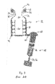
flange assembly 84 to thevalve body 36 can be carried out by press-fitting as indicating by the arrows 114 representing the pressing force 114. Alternatively theflange assembly 84 can also be mounted to thevalve body 36 by snap-fitting, screwing or welding. Due to the force 114 acting on to the whole assembly during mounting of theflange assembly 84 and thevalve body 36 together, thedummy block 108 is provided in order to avoid a damage on thevalve seat 42. After assembly thedummy block 108 is removed. -
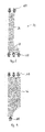
Fig. 6 and fig. 7 show a comparison of the flow of thefuel 16 through the arrangement as shown infig. 4 compared to the arrangement of the prior art comprising the domeshape end portion 58 on theoutlet conduct 28. As can be seen, a symmetric flow of thefuel 16 can be achieved in the arrangement according tofig. 6 , whereas in the arrangement according tofig. 7 , where a constriction 116 and thebend 60 are obstructing the flow of thefuel 16, a radial force is acting on thespring 44 and thevalve body 36. -
Fig. 8 and fig. 9 show theaxial load 118 acting on thevalve assembly 34 and thevalve piston chamber 48, respectively. - Both the
valve assembly 34 and thevalve piston 46 comprise a stiffness acting against thisaxial load 118. It was observed that the total stiffness, i.e. the stiffness sum of thevalve assembly 34 and thevalve piston 46 is about 20 % higher than the stiffness sum in the arrangements of the prior art according tofig.2 andfig.3 . -
- 10
- fuel injector
- 12
- valve pin
- 14
- injector nozzle
- 16
- fuel
- 18
- control unit
- 20
- control chamber
- 22
- control piston
- 24
- inlet conduct
- 26
- inlet throttle
- 28
- outlet conduct
- 30
- outlet throttle
- 32
- control valve unit
- 34
- valve assembly
- 36
- valve body
- 38
- valve cluster
- 40
- valve chamber
- 42
- valve seat
- 44
- spring
- 46
- valve piston
- 48
- valve piston chamber
- 50
- high pressure area
- 52
- low pressure area
- 54
- connecting channel
- 56
- cavitating throttle
- 58
- dome shaped end portion
- 60
- bend
- 62
- support
- 64
- end wall
- 66
- housing
- 68
- bore
- 70
- tension spring
- 72
- hollow space
- 74
- extension length
- 76
- extension axis
- 78
- diameter (valve chamber)
- 80
- throttle plate
- 82
- end portion (valve body)
- 84
- flange assembly
- 86
- central bore
- 88
- flange
- 90
- spring end
- 92
- tapered shape
- 94
- diameter (spring)
- 96
- first end portion
- 98
- diameter (valve body)
- 100
- second end portion
- 102
- step
- 104
- second valve seat
- 106
- circumferential area
- 108
- dummy block
- 110
- diameter (dummy block)
- 112
- diameter (valve cluster)
- 114
- pressing force
- 116
- constriction
- 118
- axial load
Claims (10)
- Control unit (18) to control a valve pin (12) of a fuel injector (10),
the control unit (18) comprising a control chamber (20) to exert a predefined pressure force onto a control piston (22) to move the valve pin (12) with a predefined stroke, and a control valve unit (32) to control the pressure force exerted by the control chamber (20),
the control valve unit (32) comprising a high pressure area (50) and a low pressure area (52) being connected to each other via a connecting channel (54), the control valve unit (32) further comprising a valve assembly(34) to block and unblock the connecting channel (54) upon actuation of the valve assembly(34),
wherein in the high pressure area (50) a valve chamber (40) is arranged comprising a valve seat (42) and a valve cluster (38) of the valve assembly (34),
wherein in the low pressure area (52) a valve piston chamber (48) is arranged comprising a valve body (36) of the valve assembly (34) and a valve piston (46) to actuate the valve assembly (34),
wherein a spring (44) is provided to bias the valve cluster (38) onto the valve seat (42), wherein the spring (44) is arranged in the valve piston chamber (48) in the low pressure area (52). - Control unit (18) according to claim 1,
characterized in that the control valve unit (32) is located in a housing (66) comprising a bore (68) to form the valve piston chamber (48), the bore (68) having an end wall (64) located adjoining to the connecting channel (54), wherein the spring (44) is supported by the end wall (64). - Control unit (18) according to one of the claims 1 or 2, wherein the valve body (36) comprises an end portion (82) located adjoining to the valve piston (46), wherein a flange assembly (84) is arranged at the end portion (82) and comprises a flange (88) extending away from the end portion (96) in a perpendicular direction relative to an extension axis (76) of the valve body (36).
- Control unit (18) according to claim 2 and 3, characterized in that the spring (44) comprises a spring end (90) opposite to the end wall (64), the spring end (90) being mounted to the flange assembly (84).
- Control unit (18) according to one of the claims 1 to 4, characterized in that the spring (44) comprises a tapered shape (92), the spring (44) in particular having its largest diameter (94) at a first end portion (96) of the valve body (36) next to the valve cluster (38).
- Control unit (18) according to one of the claims 1 to 5, characterized in that an outlet throttle (30) is arranged between the control chamber (20) and the valve chamber (40), wherein the outlet throttle (30) is in direct contact with the valve chamber(40).
- Control unit (18) according to one of the claims 1 to 6, characterized in that a diameter (78) of the valve chamber (40) is larger than an extension length (74) of the valve chamber (40) parallel to an extension axis (76) of the valve body (36).
- Control unit (18) according to one of the claims 1 to 7, characterized in that the valve body (36) comprises an extension axis(76), wherein a diameter (98) of the valve body (36) around the extension axis (76) is continuously increasing along the extension axis (76) from the valve cluster (38) to a second end portion (100) opposite the valve cluster (38).
- Fuel injector (10) with a valve pin (12) to open and close at least one injecting nozzle (14) of the fuel injector (10), the fuel injector (10) comprising a control unit (18) according to one of the claims 1 to 8.
- Method to provide a control valve unit (32) to control a pressure force exerted by a control chamber (20) onto a control piston (22) to move a valve pin (12) of a fuel injector (10), the method comprising the steps of:a) providing a valve assembly (34) with a valve body (36) and a valve cluster (38);b) providing a flange assembly (84) with a central bore (86) and a spring (44) mounted on a circumferential area (106) of the flange assembly (84);c) providing a housing (66) with bores (68) to form a valve chamber(40), a connecting channel (54) and a valve piston chamber (48);d) providing a dummy block (108) comprising a diameter (110) corresponding to a diameter (112) of the valve cluster (38) ;e) arranging the dummy block (108) in the valve chamber (40) ;f) arranging the valve assembly (34) on top of the dummy block (108) such that the valve cluster (38) is in contact with the dummy block (108) and such that the valve body (36) extends into the piston chamber(48);g) arranging the flange assembly (84) on top of the valve body (36) such that the valve body (36) is in contact with a wall area of the central bore (86);h) fixing the flange assembly (84) to the valve body (36) by welding, press-fitting, snap-fitting and/or screwing.
Priority Applications (1)
| Application Number | Priority Date | Filing Date | Title |
|---|---|---|---|
| EP14177593.2A EP2975257B1 (en) | 2014-07-18 | 2014-07-18 | Control unit to control a valve pin of a fuel injector and fuel injector |
Applications Claiming Priority (1)
| Application Number | Priority Date | Filing Date | Title |
|---|---|---|---|
| EP14177593.2A EP2975257B1 (en) | 2014-07-18 | 2014-07-18 | Control unit to control a valve pin of a fuel injector and fuel injector |
Publications (2)
| Publication Number | Publication Date |
|---|---|
| EP2975257A1 true EP2975257A1 (en) | 2016-01-20 |
| EP2975257B1 EP2975257B1 (en) | 2018-01-10 |
Family
ID=51205313
Family Applications (1)
| Application Number | Title | Priority Date | Filing Date |
|---|---|---|---|
| EP14177593.2A Active EP2975257B1 (en) | 2014-07-18 | 2014-07-18 | Control unit to control a valve pin of a fuel injector and fuel injector |
Country Status (1)
| Country | Link |
|---|---|
| EP (1) | EP2975257B1 (en) |
Cited By (1)
| Publication number | Priority date | Publication date | Assignee | Title |
|---|---|---|---|---|
| CN111535958A (en) * | 2020-05-29 | 2020-08-14 | 一汽解放汽车有限公司 | A dual fuel injector and its injection method |
Citations (7)
| Publication number | Priority date | Publication date | Assignee | Title |
|---|---|---|---|---|
| DE19732802A1 (en) * | 1997-07-30 | 1999-02-04 | Bosch Gmbh Robert | Fuel injection device for internal combustion engines |
| WO1999034111A1 (en) * | 1997-12-23 | 1999-07-08 | Siemens Aktiengesellschaft | Injection valve with control valve |
| DE19860397A1 (en) * | 1998-12-28 | 2000-06-29 | Bosch Gmbh Robert | Fuel injection device for internal combustion engines |
| WO2001051797A2 (en) * | 2000-01-13 | 2001-07-19 | Robert Bosch Gmbh | Control valve for an injector in a fuel injection system for internal combustion engines with pressure amplification in the control chamber |
| WO2003058052A1 (en) * | 2002-01-09 | 2003-07-17 | Robert Bosch Gmbh | Control element for injectors with switched injector pin |
| US8459232B2 (en) | 2007-09-06 | 2013-06-11 | Continental Automotive Gmbh | Injection system, and method for the production of an injection system |
| EP2394048B1 (en) | 2009-02-03 | 2013-08-07 | Continental Automotive GmbH | Injector assembly for an injection valve |
-
2014
- 2014-07-18 EP EP14177593.2A patent/EP2975257B1/en active Active
Patent Citations (7)
| Publication number | Priority date | Publication date | Assignee | Title |
|---|---|---|---|---|
| DE19732802A1 (en) * | 1997-07-30 | 1999-02-04 | Bosch Gmbh Robert | Fuel injection device for internal combustion engines |
| WO1999034111A1 (en) * | 1997-12-23 | 1999-07-08 | Siemens Aktiengesellschaft | Injection valve with control valve |
| DE19860397A1 (en) * | 1998-12-28 | 2000-06-29 | Bosch Gmbh Robert | Fuel injection device for internal combustion engines |
| WO2001051797A2 (en) * | 2000-01-13 | 2001-07-19 | Robert Bosch Gmbh | Control valve for an injector in a fuel injection system for internal combustion engines with pressure amplification in the control chamber |
| WO2003058052A1 (en) * | 2002-01-09 | 2003-07-17 | Robert Bosch Gmbh | Control element for injectors with switched injector pin |
| US8459232B2 (en) | 2007-09-06 | 2013-06-11 | Continental Automotive Gmbh | Injection system, and method for the production of an injection system |
| EP2394048B1 (en) | 2009-02-03 | 2013-08-07 | Continental Automotive GmbH | Injector assembly for an injection valve |
Cited By (2)
| Publication number | Priority date | Publication date | Assignee | Title |
|---|---|---|---|---|
| CN111535958A (en) * | 2020-05-29 | 2020-08-14 | 一汽解放汽车有限公司 | A dual fuel injector and its injection method |
| CN111535958B (en) * | 2020-05-29 | 2021-07-13 | 一汽解放汽车有限公司 | A dual fuel injector and its injection method |
Also Published As
| Publication number | Publication date |
|---|---|
| EP2975257B1 (en) | 2018-01-10 |
Similar Documents
| Publication | Publication Date | Title |
|---|---|---|
| JP5069288B2 (en) | High-pressure fuel pump for common rail | |
| US9133944B2 (en) | Switching valve to control a fluid subject to high pressure | |
| EP2126427B1 (en) | Non-return valve and injector with hydraulic booster and non-return valve | |
| US20050061372A1 (en) | Pressure regulator assembly | |
| CN104302907A (en) | Pressure-limiting valve | |
| CN107076089B (en) | High-pressure fuel pump for a fuel system of an internal combustion engine | |
| KR102082562B1 (en) | Fuel injection system for an internal combustion engine | |
| CN101384847A (en) | Pilot operated pressure limiting valve | |
| US20200200066A1 (en) | Axial fluid spray nozzle with vent valve | |
| KR20180021200A (en) | Integrated Check-Relief Valve | |
| JPH06213357A (en) | Magnet valve | |
| CZ296996B6 (en) | Common rail injector | |
| CN104769272A (en) | Valve arrangement | |
| JP2017519932A (en) | Fuel injector | |
| CN110741151A (en) | Gas pressure limiting valve for controlling and discharging gaseous media with annular gap support | |
| EP2975257B1 (en) | Control unit to control a valve pin of a fuel injector and fuel injector | |
| GB2571933A (en) | Outlet metering valve for high pressure fuel pump | |
| KR20020069266A (en) | Fuel injection pump for internal combustion engines, especially diesel engines | |
| EP2405127A1 (en) | A fuel injector for internal combustion engines | |
| US6988514B2 (en) | Hydroaccumulator, in a particular a bladder accumulator | |
| CN1987128A (en) | Hydraulic valve | |
| US11428327B2 (en) | Check valve | |
| EP1845253B1 (en) | Fuel injector for an internal-combustion engine | |
| EP3149322B1 (en) | A safety valve arrangement for a common rail fuel in-jection system and a common rail fuel injection system | |
| JP2019132275A (en) | High-pressure connection device for high-pressure fuel pump of fuel injection system, and high-pressure fuel pump |
Legal Events
| Date | Code | Title | Description |
|---|---|---|---|
| PUAI | Public reference made under article 153(3) epc to a published international application that has entered the european phase |
Free format text: ORIGINAL CODE: 0009012 |
|
| AK | Designated contracting states |
Kind code of ref document: A1 Designated state(s): AL AT BE BG CH CY CZ DE DK EE ES FI FR GB GR HR HU IE IS IT LI LT LU LV MC MK MT NL NO PL PT RO RS SE SI SK SM TR |
|
| AX | Request for extension of the european patent |
Extension state: BA ME |
|
| 17P | Request for examination filed |
Effective date: 20160720 |
|
| RBV | Designated contracting states (corrected) |
Designated state(s): AL AT BE BG CH CY CZ DE DK EE ES FI FR GB GR HR HU IE IS IT LI LT LU LV MC MK MT NL NO PL PT RO RS SE SI SK SM TR |
|
| GRAP | Despatch of communication of intention to grant a patent |
Free format text: ORIGINAL CODE: EPIDOSNIGR1 |
|
| INTG | Intention to grant announced |
Effective date: 20170823 |
|
| GRAS | Grant fee paid |
Free format text: ORIGINAL CODE: EPIDOSNIGR3 |
|
| GRAA | (expected) grant |
Free format text: ORIGINAL CODE: 0009210 |
|
| AK | Designated contracting states |
Kind code of ref document: B1 Designated state(s): AL AT BE BG CH CY CZ DE DK EE ES FI FR GB GR HR HU IE IS IT LI LT LU LV MC MK MT NL NO PL PT RO RS SE SI SK SM TR |
|
| REG | Reference to a national code |
Ref country code: CH Ref legal event code: EP Ref country code: AT Ref legal event code: REF Ref document number: 962701 Country of ref document: AT Kind code of ref document: T Effective date: 20180115 |
|
| REG | Reference to a national code |
Ref country code: IE Ref legal event code: FG4D |
|
| REG | Reference to a national code |
Ref country code: DE Ref legal event code: R096 Ref document number: 602014019609 Country of ref document: DE |
|
| REG | Reference to a national code |
Ref country code: NL Ref legal event code: MP Effective date: 20180110 |
|
| REG | Reference to a national code |
Ref country code: AT Ref legal event code: MK05 Ref document number: 962701 Country of ref document: AT Kind code of ref document: T Effective date: 20180110 |
|
| PG25 | Lapsed in a contracting state [announced via postgrant information from national office to epo] |
Ref country code: NL Free format text: LAPSE BECAUSE OF FAILURE TO SUBMIT A TRANSLATION OF THE DESCRIPTION OR TO PAY THE FEE WITHIN THE PRESCRIBED TIME-LIMIT Effective date: 20180110 |
|
| REG | Reference to a national code |
Ref country code: FR Ref legal event code: PLFP Year of fee payment: 5 |
|
| PG25 | Lapsed in a contracting state [announced via postgrant information from national office to epo] |
Ref country code: ES Free format text: LAPSE BECAUSE OF FAILURE TO SUBMIT A TRANSLATION OF THE DESCRIPTION OR TO PAY THE FEE WITHIN THE PRESCRIBED TIME-LIMIT Effective date: 20180110 Ref country code: LT Free format text: LAPSE BECAUSE OF FAILURE TO SUBMIT A TRANSLATION OF THE DESCRIPTION OR TO PAY THE FEE WITHIN THE PRESCRIBED TIME-LIMIT Effective date: 20180110 Ref country code: NO Free format text: LAPSE BECAUSE OF FAILURE TO SUBMIT A TRANSLATION OF THE DESCRIPTION OR TO PAY THE FEE WITHIN THE PRESCRIBED TIME-LIMIT Effective date: 20180410 Ref country code: CY Free format text: LAPSE BECAUSE OF FAILURE TO SUBMIT A TRANSLATION OF THE DESCRIPTION OR TO PAY THE FEE WITHIN THE PRESCRIBED TIME-LIMIT Effective date: 20180110 Ref country code: HR Free format text: LAPSE BECAUSE OF FAILURE TO SUBMIT A TRANSLATION OF THE DESCRIPTION OR TO PAY THE FEE WITHIN THE PRESCRIBED TIME-LIMIT Effective date: 20180110 Ref country code: FI Free format text: LAPSE BECAUSE OF FAILURE TO SUBMIT A TRANSLATION OF THE DESCRIPTION OR TO PAY THE FEE WITHIN THE PRESCRIBED TIME-LIMIT Effective date: 20180110 |
|
| PG25 | Lapsed in a contracting state [announced via postgrant information from national office to epo] |
Ref country code: IS Free format text: LAPSE BECAUSE OF FAILURE TO SUBMIT A TRANSLATION OF THE DESCRIPTION OR TO PAY THE FEE WITHIN THE PRESCRIBED TIME-LIMIT Effective date: 20180510 Ref country code: RS Free format text: LAPSE BECAUSE OF FAILURE TO SUBMIT A TRANSLATION OF THE DESCRIPTION OR TO PAY THE FEE WITHIN THE PRESCRIBED TIME-LIMIT Effective date: 20180110 Ref country code: PL Free format text: LAPSE BECAUSE OF FAILURE TO SUBMIT A TRANSLATION OF THE DESCRIPTION OR TO PAY THE FEE WITHIN THE PRESCRIBED TIME-LIMIT Effective date: 20180110 Ref country code: SE Free format text: LAPSE BECAUSE OF FAILURE TO SUBMIT A TRANSLATION OF THE DESCRIPTION OR TO PAY THE FEE WITHIN THE PRESCRIBED TIME-LIMIT Effective date: 20180110 Ref country code: LV Free format text: LAPSE BECAUSE OF FAILURE TO SUBMIT A TRANSLATION OF THE DESCRIPTION OR TO PAY THE FEE WITHIN THE PRESCRIBED TIME-LIMIT Effective date: 20180110 Ref country code: AT Free format text: LAPSE BECAUSE OF FAILURE TO SUBMIT A TRANSLATION OF THE DESCRIPTION OR TO PAY THE FEE WITHIN THE PRESCRIBED TIME-LIMIT Effective date: 20180110 Ref country code: GR Free format text: LAPSE BECAUSE OF FAILURE TO SUBMIT A TRANSLATION OF THE DESCRIPTION OR TO PAY THE FEE WITHIN THE PRESCRIBED TIME-LIMIT Effective date: 20180411 Ref country code: BG Free format text: LAPSE BECAUSE OF FAILURE TO SUBMIT A TRANSLATION OF THE DESCRIPTION OR TO PAY THE FEE WITHIN THE PRESCRIBED TIME-LIMIT Effective date: 20180410 |
|
| REG | Reference to a national code |
Ref country code: DE Ref legal event code: R097 Ref document number: 602014019609 Country of ref document: DE |
|
| PG25 | Lapsed in a contracting state [announced via postgrant information from national office to epo] |
Ref country code: RO Free format text: LAPSE BECAUSE OF FAILURE TO SUBMIT A TRANSLATION OF THE DESCRIPTION OR TO PAY THE FEE WITHIN THE PRESCRIBED TIME-LIMIT Effective date: 20180110 Ref country code: AL Free format text: LAPSE BECAUSE OF FAILURE TO SUBMIT A TRANSLATION OF THE DESCRIPTION OR TO PAY THE FEE WITHIN THE PRESCRIBED TIME-LIMIT Effective date: 20180110 Ref country code: IT Free format text: LAPSE BECAUSE OF FAILURE TO SUBMIT A TRANSLATION OF THE DESCRIPTION OR TO PAY THE FEE WITHIN THE PRESCRIBED TIME-LIMIT Effective date: 20180110 Ref country code: EE Free format text: LAPSE BECAUSE OF FAILURE TO SUBMIT A TRANSLATION OF THE DESCRIPTION OR TO PAY THE FEE WITHIN THE PRESCRIBED TIME-LIMIT Effective date: 20180110 |
|
| PLBE | No opposition filed within time limit |
Free format text: ORIGINAL CODE: 0009261 |
|
| STAA | Information on the status of an ep patent application or granted ep patent |
Free format text: STATUS: NO OPPOSITION FILED WITHIN TIME LIMIT |
|
| PG25 | Lapsed in a contracting state [announced via postgrant information from national office to epo] |
Ref country code: DK Free format text: LAPSE BECAUSE OF FAILURE TO SUBMIT A TRANSLATION OF THE DESCRIPTION OR TO PAY THE FEE WITHIN THE PRESCRIBED TIME-LIMIT Effective date: 20180110 Ref country code: SM Free format text: LAPSE BECAUSE OF FAILURE TO SUBMIT A TRANSLATION OF THE DESCRIPTION OR TO PAY THE FEE WITHIN THE PRESCRIBED TIME-LIMIT Effective date: 20180110 Ref country code: SK Free format text: LAPSE BECAUSE OF FAILURE TO SUBMIT A TRANSLATION OF THE DESCRIPTION OR TO PAY THE FEE WITHIN THE PRESCRIBED TIME-LIMIT Effective date: 20180110 Ref country code: CZ Free format text: LAPSE BECAUSE OF FAILURE TO SUBMIT A TRANSLATION OF THE DESCRIPTION OR TO PAY THE FEE WITHIN THE PRESCRIBED TIME-LIMIT Effective date: 20180110 |
|
| 26N | No opposition filed |
Effective date: 20181011 |
|
| PG25 | Lapsed in a contracting state [announced via postgrant information from national office to epo] |
Ref country code: SI Free format text: LAPSE BECAUSE OF FAILURE TO SUBMIT A TRANSLATION OF THE DESCRIPTION OR TO PAY THE FEE WITHIN THE PRESCRIBED TIME-LIMIT Effective date: 20180110 |
|
| REG | Reference to a national code |
Ref country code: CH Ref legal event code: PL |
|
| PG25 | Lapsed in a contracting state [announced via postgrant information from national office to epo] |
Ref country code: LU Free format text: LAPSE BECAUSE OF NON-PAYMENT OF DUE FEES Effective date: 20180718 Ref country code: MC Free format text: LAPSE BECAUSE OF FAILURE TO SUBMIT A TRANSLATION OF THE DESCRIPTION OR TO PAY THE FEE WITHIN THE PRESCRIBED TIME-LIMIT Effective date: 20180110 |
|
| REG | Reference to a national code |
Ref country code: BE Ref legal event code: MM Effective date: 20180731 |
|
| REG | Reference to a national code |
Ref country code: IE Ref legal event code: MM4A |
|
| PG25 | Lapsed in a contracting state [announced via postgrant information from national office to epo] |
Ref country code: IE Free format text: LAPSE BECAUSE OF NON-PAYMENT OF DUE FEES Effective date: 20180718 Ref country code: CH Free format text: LAPSE BECAUSE OF NON-PAYMENT OF DUE FEES Effective date: 20180731 Ref country code: LI Free format text: LAPSE BECAUSE OF NON-PAYMENT OF DUE FEES Effective date: 20180731 |
|
| PG25 | Lapsed in a contracting state [announced via postgrant information from national office to epo] |
Ref country code: BE Free format text: LAPSE BECAUSE OF NON-PAYMENT OF DUE FEES Effective date: 20180731 |
|
| PG25 | Lapsed in a contracting state [announced via postgrant information from national office to epo] |
Ref country code: MT Free format text: LAPSE BECAUSE OF NON-PAYMENT OF DUE FEES Effective date: 20180718 |
|
| PG25 | Lapsed in a contracting state [announced via postgrant information from national office to epo] |
Ref country code: TR Free format text: LAPSE BECAUSE OF FAILURE TO SUBMIT A TRANSLATION OF THE DESCRIPTION OR TO PAY THE FEE WITHIN THE PRESCRIBED TIME-LIMIT Effective date: 20180110 |
|
| PG25 | Lapsed in a contracting state [announced via postgrant information from national office to epo] |
Ref country code: PT Free format text: LAPSE BECAUSE OF FAILURE TO SUBMIT A TRANSLATION OF THE DESCRIPTION OR TO PAY THE FEE WITHIN THE PRESCRIBED TIME-LIMIT Effective date: 20180110 |
|
| REG | Reference to a national code |
Ref country code: DE Ref legal event code: R081 Ref document number: 602014019609 Country of ref document: DE Owner name: VITESCO TECHNOLOGIES GMBH, DE Free format text: FORMER OWNER: CONTINENTAL AUTOMOTIVE GMBH, 30165 HANNOVER, DE |
|
| PG25 | Lapsed in a contracting state [announced via postgrant information from national office to epo] |
Ref country code: HU Free format text: LAPSE BECAUSE OF FAILURE TO SUBMIT A TRANSLATION OF THE DESCRIPTION OR TO PAY THE FEE WITHIN THE PRESCRIBED TIME-LIMIT; INVALID AB INITIO Effective date: 20140718 Ref country code: MK Free format text: LAPSE BECAUSE OF NON-PAYMENT OF DUE FEES Effective date: 20180110 |
|
| REG | Reference to a national code |
Ref country code: DE Ref legal event code: R081 Ref document number: 602014019609 Country of ref document: DE Owner name: SCHAEFFLER TECHNOLOGIES AG & CO. KG, DE Free format text: FORMER OWNER: VITESCO TECHNOLOGIES GMBH, 30165 HANNOVER, DE Ref country code: DE Ref legal event code: R081 Ref document number: 602014019609 Country of ref document: DE Owner name: VITESCO TECHNOLOGIES GMBH, DE Free format text: FORMER OWNER: VITESCO TECHNOLOGIES GMBH, 30165 HANNOVER, DE |
|
| REG | Reference to a national code |
Ref country code: GB Ref legal event code: 732E Free format text: REGISTERED BETWEEN 20230427 AND 20230503 |
|
| P01 | Opt-out of the competence of the unified patent court (upc) registered |
Effective date: 20230530 |
|
| REG | Reference to a national code |
Ref country code: DE Ref legal event code: R081 Ref document number: 602014019609 Country of ref document: DE Owner name: SCHAEFFLER TECHNOLOGIES AG & CO. KG, DE Free format text: FORMER OWNER: VITESCO TECHNOLOGIES GMBH, 93055 REGENSBURG, DE |
|
| PGFP | Annual fee paid to national office [announced via postgrant information from national office to epo] |
Ref country code: DE Payment date: 20250731 Year of fee payment: 12 |
|
| PGFP | Annual fee paid to national office [announced via postgrant information from national office to epo] |
Ref country code: GB Payment date: 20250722 Year of fee payment: 12 |
|
| PGFP | Annual fee paid to national office [announced via postgrant information from national office to epo] |
Ref country code: FR Payment date: 20250725 Year of fee payment: 12 |