EP2975240A1 - Self-purging fuel nozzle system for a gas turbine engine - Google Patents
Self-purging fuel nozzle system for a gas turbine engine Download PDFInfo
- Publication number
- EP2975240A1 EP2975240A1 EP15177397.5A EP15177397A EP2975240A1 EP 2975240 A1 EP2975240 A1 EP 2975240A1 EP 15177397 A EP15177397 A EP 15177397A EP 2975240 A1 EP2975240 A1 EP 2975240A1
- Authority
- EP
- European Patent Office
- Prior art keywords
- self
- fuel
- recited
- purge
- purge system
- Prior art date
- Legal status (The legal status is an assumption and is not a legal conclusion. Google has not performed a legal analysis and makes no representation as to the accuracy of the status listed.)
- Granted
Links
Images



Classifications
-
- F—MECHANICAL ENGINEERING; LIGHTING; HEATING; WEAPONS; BLASTING
- F02—COMBUSTION ENGINES; HOT-GAS OR COMBUSTION-PRODUCT ENGINE PLANTS
- F02C—GAS-TURBINE PLANTS; AIR INTAKES FOR JET-PROPULSION PLANTS; CONTROLLING FUEL SUPPLY IN AIR-BREATHING JET-PROPULSION PLANTS
- F02C7/00—Features, components parts, details or accessories, not provided for in, or of interest apart form groups F02C1/00 - F02C6/00; Air intakes for jet-propulsion plants
- F02C7/22—Fuel supply systems
- F02C7/232—Fuel valves; Draining valves or systems
-
- F—MECHANICAL ENGINEERING; LIGHTING; HEATING; WEAPONS; BLASTING
- F23—COMBUSTION APPARATUS; COMBUSTION PROCESSES
- F23R—GENERATING COMBUSTION PRODUCTS OF HIGH PRESSURE OR HIGH VELOCITY, e.g. GAS-TURBINE COMBUSTION CHAMBERS
- F23R3/00—Continuous combustion chambers using liquid or gaseous fuel
- F23R3/28—Continuous combustion chambers using liquid or gaseous fuel characterised by the fuel supply
-
- B—PERFORMING OPERATIONS; TRANSPORTING
- B33—ADDITIVE MANUFACTURING TECHNOLOGY
- B33Y—ADDITIVE MANUFACTURING, i.e. MANUFACTURING OF THREE-DIMENSIONAL [3D] OBJECTS BY ADDITIVE DEPOSITION, ADDITIVE AGGLOMERATION OR ADDITIVE LAYERING, e.g. BY 3D PRINTING, STEREOLITHOGRAPHY OR SELECTIVE LASER SINTERING
- B33Y80/00—Products made by additive manufacturing
-
- F—MECHANICAL ENGINEERING; LIGHTING; HEATING; WEAPONS; BLASTING
- F05—INDEXING SCHEMES RELATING TO ENGINES OR PUMPS IN VARIOUS SUBCLASSES OF CLASSES F01-F04
- F05D—INDEXING SCHEME FOR ASPECTS RELATING TO NON-POSITIVE-DISPLACEMENT MACHINES OR ENGINES, GAS-TURBINES OR JET-PROPULSION PLANTS
- F05D2220/00—Application
- F05D2220/30—Application in turbines
- F05D2220/32—Application in turbines in gas turbines
-
- F—MECHANICAL ENGINEERING; LIGHTING; HEATING; WEAPONS; BLASTING
- F05—INDEXING SCHEMES RELATING TO ENGINES OR PUMPS IN VARIOUS SUBCLASSES OF CLASSES F01-F04
- F05D—INDEXING SCHEME FOR ASPECTS RELATING TO NON-POSITIVE-DISPLACEMENT MACHINES OR ENGINES, GAS-TURBINES OR JET-PROPULSION PLANTS
- F05D2230/00—Manufacture
- F05D2230/30—Manufacture with deposition of material
-
- F—MECHANICAL ENGINEERING; LIGHTING; HEATING; WEAPONS; BLASTING
- F05—INDEXING SCHEMES RELATING TO ENGINES OR PUMPS IN VARIOUS SUBCLASSES OF CLASSES F01-F04
- F05D—INDEXING SCHEME FOR ASPECTS RELATING TO NON-POSITIVE-DISPLACEMENT MACHINES OR ENGINES, GAS-TURBINES OR JET-PROPULSION PLANTS
- F05D2240/00—Components
- F05D2240/35—Combustors or associated equipment
-
- F—MECHANICAL ENGINEERING; LIGHTING; HEATING; WEAPONS; BLASTING
- F05—INDEXING SCHEMES RELATING TO ENGINES OR PUMPS IN VARIOUS SUBCLASSES OF CLASSES F01-F04
- F05D—INDEXING SCHEME FOR ASPECTS RELATING TO NON-POSITIVE-DISPLACEMENT MACHINES OR ENGINES, GAS-TURBINES OR JET-PROPULSION PLANTS
- F05D2260/00—Function
- F05D2260/60—Fluid transfer
- F05D2260/602—Drainage
Definitions
- the present disclosure relates to a gas turbine engine and, more particularly, to a fuel nozzle system therefor.
- Gas turbine engines include a compressor section to pressurize a supply of air, a combustor section to burn a hydrocarbon fuel in the presence of the pressurized air, and a turbine section to extract energy from the resultant combustion gases.
- the combustor section generally includes a multiple of circumferentially distributed fuel nozzles that axially project into a forward section of a combustion chamber to supply the fuel for mixing with the pressurized air.
- fuel passages are drained so as not to drip fuel into the combustion chamber after engine shut down.
- fuel lines also need to be purged of fuel to avoid coking when that stage is not operated.
- a self-purge system includes an additively manufactured purge valve assembly in communication with a fuel passage to selectively purge said fuel passage.
- the fuel passage is in communication with a fuel nozzle.
- the fuel passage is a portion of a fuel manifold.
- the fuel passage is a fuel circuit of a fuel nozzle.
- the additively manufactured purge valve assembly is in communication with an accumulator volume and a pressure source.
- the accumulator volume contains an accumulator piston with a valve.
- the self-purge system includes a spring that biases the accumulator piston.
- the accumulator piston operates in response to pressure source and the spring.
- a further embodiment of any of the foregoing embodiments of the present disclosure includes a backflow valve in communication with the fuel passage.
- the additively manufactured purge valve assembly includes a dual ball valve.
- the dual ball valve includes two, one-way ball valve assemblies.
- any of the foregoing embodiments of the present disclosure includes a spring that biases an accumulator piston, the accumulator piston in communication with the additively manufactured purge valve assembly.
- the accumulator piston is sealed by a bladder seal.
- a further embodiment of any of the foregoing embodiments of the present disclosure includes a bleed air valve in communication with the bladder seal.
- a fuel nozzle system of a gas turbine engine includes a fuel nozzle and an additively manufactured purge valve assembly in communication with a fuel passage of the fuel nozzle to selectively purge said fuel passage.
- the additively manufactured purge valve assembly is in communication with an accumulator volume and a pressure source.
- the accumulator volume contains an accumulator piston with a valve.
- the additively manufactured purge valve assembly includes a dual ball valve.
- the additively manufactured purge valve assembly is integrated with the fuel nozzle.
- At least a portion of the additively manufactured purge valve assembly is integrated with a flange of the fuel nozzle.
- FIG. 1 schematically illustrates a gas turbine engine 20.
- the gas turbine engine 20 is disclosed herein as a two-spool turbofan that generally incorporates a fan section 22, a compressor section 24, a combustor section 26 and a turbine section 28.
- Alternative engines might include an augmentor section (not shown) among other systems or features.
- the fan section 22 drives air along a bypass flowpath while the compressor section 24 drives air along a core flowpath for compression and communication into the combustor section 26, then expansion through the turbine section 28.
- FIG. 1 schematically illustrates a gas turbine engine 20.
- the gas turbine engine 20 is disclosed herein as a two-spool turbofan that generally incorporates a fan section 22, a compressor section 24, a combustor section 26 and a turbine section 28.
- Alternative engines might include an augmentor section (not shown) among other systems or features.
- the fan section 22 drives air along a bypass flowpath while the compressor section 24 drives air along a core flowpath for compression and communication into the combustor section 26,
- the engine 20 generally includes a low spool 30 and a high spool 32 mounted for rotation about an engine central longitudinal axis A relative to an engine case structure 36 via several bearing structures 38.
- the low spool 30 generally includes an inner shaft 40 that interconnects a fan 42, a low pressure compressor (“LPC”) 44 and a low pressure turbine (“LPT”) 46.
- the inner shaft 40 drives the fan 42 directly or through a geared architecture 48 to drive the fan 42 at a lower speed than the low spool 30.
- An exemplary reduction transmission is an epicyclic transmission, namely a planetary or star gear system.
- the high spool 32 includes an outer shaft 50 that interconnects a high pressure compressor (“HPC”) 52 and high pressure turbine (“HPT”) 54.
- a combustor 56 is arranged between the high pressure compressor 52 and the high pressure turbine 54.
- the inner shaft 40 and the outer shaft 50 are concentric and rotate about the engine central longitudinal axis A which is collinear with their longitudinal axes.
- Core airflow is compressed by the low pressure compressor 44, then the high pressure compressor 52, mixed with the fuel and burned in the combustor 56, then expanded over the HPT 54 and LPT 46.
- the HPT 54 and LPT 46 rotationally drive the respective high spool 32 and low spool 30 in response to the expansion.
- the combustor 56 generally includes an outer liner 60, an inner liner 62 and a diffuser case module 64.
- the outer liner 60 and the inner liner 62 are spaced apart such that a combustion chamber 66 is defined therebetween.
- the combustion chamber 66 is generally annular in shape.
- the outer liner 60 and the inner liner 62 are spaced radially inward the outer diffuser case 64 to define an annular outer plenum 76 and an annular inner plenum 78. It should be understood that although a particular combustor is illustrated, other combustor types with various combustor liner arrangements will also benefit herefrom. It should be further understood that the disclosed cooling flow paths are but an illustrated embodiment and should not be limited only thereto.
- Each liner 60, 62 contain the combustion products for direction toward the turbine section 28.
- Each liner 60, 62 generally includes a respective support shell 68, 70 which supports one or more heat shields 72, 74 that are attached there to with fasteners 75.
- the combustor 56 also includes a forward assembly 80 downstream of the compressor section 24 to receive compressed airflow therefrom.
- the forward assembly 80 generally includes an annular hood 82, a bulkhead assembly 84, a multiple of fuel nozzles 86 (one shown) and a multiple of swirlers 90 (one shown).
- Each swirler 90 is circumferentially aligned with one of the hood ports 94 to project through the bulkhead assembly 84.
- Each bulkhead assembly 84 includes a bulkhead support shell 96 secured to the liners 60, 62, and a multiple of circumferentially distributed bulkhead heat shields 98 secured to the bulkhead support shell 96.
- the annular hood 82 extends radially between, and is secured to, the forwardmost ends of the liners 60, 62.
- the annular hood 82 includes a multiple of circumferentially distributed hood ports 94 that accommodate the respective fuel nozzle 86 and introduce air into the forward end of the combustion chamber 66 through a central opening.
- Each fuel nozzle 86 may be secured to the diffuser case module 64 to project through a respective hood port 94 and swirler 90.
- the forward assembly 80 introduces core combustion air into the forward end of the combustion chamber 66 while the remainder enters the annular outer plenum 76 and the annular inner plenum 78.
- the multiple of fuel nozzles 86 and surrounding structure generate a blended fuel-air mixture that supports combustion in the combustion chamber 66.
- the support shells 68, 70 are mounted to a first row of Nozzle Guide Vanes (NGVs) 54A in the HPT 54.
- NGVs 54A are static engine components which direct core airflow combustion gases onto the turbine blades of the first turbine rotor in the HPT 54 28 to facilitate the conversion of pressure energy into kinetic energy.
- the combustion gases are also accelerated by the NGVs 54A because of their convergent shape and are typically given a "spin” or a "swirl” in the direction of turbine rotor rotation.
- a fuel nozzle system 92 generally includes one or more fuel nozzle supply manifolds 94 to which the multiple of fuel nozzles 86 are connected.
- the fuel nozzle supply manifolds 94 are located circumferentially around the diffuser case module 64 to communicate fuel to the multiple of fuel nozzles 86 to inject fuel under pressure into the combustor 56 for ignition. It should be appreciated that the fuel nozzle systems 92 will benefit herefrom. Furthermore, fuel nozzle systems for other engine sections such as an augmentor section will also benefit herefrom.
- the fuel nozzle system 92 includes one or more self-purge systems 96.
- the self-purge system 96 may be utilized for the entire fuel nozzle system 92, each, or subsets of fuel nozzles 86, and/or for each fuel circuit of a fuel nozzle 86. That is, each fuel nozzle may include primary and secondary fuel circuits that include a separate individual self-purge system 96 to provide independent purge.
- Each self-purge system 96 generally includes a first passage 100, a first valve 102, an accumulator 104, a second passage 106 and a purge valve assembly 108. It should be appreciated that although particular discrete components are schematically illustrated, the components may be combined and/or integrated directly into the respective fuel nozzle 86, fuel manifold 94 and/or the diffuser case module 64 via additive manufacturing.
- the relatively complex purge valve system 96 may be readily manufactured with an additive manufacturing process.
- the additive manufacturing process includes, but is not limited to, Direct Selective Laser Sintering (DSLS), Electron Beam Sintering (EBS), Electron Beam Melting (EBM), Laser Engineered Net Shaping (LENS), Laser Net Shape Manufacturing (LNSM), Direct Metal Deposition (DMD) and Laser Powder Bed Fusion (LPBF).
- DSLS Direct Selective Laser Sintering
- EBS Electron Beam Sintering
- EBM Electron Beam Melting
- LENS Laser Engineered Net Shaping
- LNSM Laser Net Shape Manufacturing
- DMD Direct Metal Deposition
- LPBF Laser Powder Bed Fusion
- the additive manufacturing process sequentially builds-up layers of atomized alloy and/or ceramic powder material that include but are not limited to, 625 Alloy, 718 Alloy, 230 Alloy, stainless steel, tool steel, cobalt chrome, titanium, nickel, aluminum, Waspaloy, Stellite, Titanium, Steels, Stainless Steels, Cobalt Chrome, Hastalloy X, and others. Alloys such as 625, 718 and 230 may have specific benefit for parts that operate in high temperature environments, such as, for example, environments typically encountered by aerospace and gas turbine engine components.
- the first passage 100 may be, for example, integral with a mount flange 110 of the fuel nozzle 86.
- the accumulator 104 communicates with the first passage 100 and a pressure source such as the compressor section 24.
- the purge valve assembly 108 communicates with the second passage 106 and the second passage 106 is in communication with the first passage 100.
- a fuel passage 112 may be within, or in communication with, the respective fuel nozzle 86, the fuel manifold 94 or a specific fuel circuit of a staged system. That is, the fuel passage 112 is representative that which is to be purged and should not be considered limited to only particular components, passages, lines, or circuits.
- One disclosed non-limiting embodiment of the purge valve assembly 108 includes a valve 120 that opens and closes a port 136 to the second passage 106.
- compressor bleed air from the compressor section 24 compresses a spring 132 of an accumulator valve 134 to seal the port 136 between the secondary passage 106 and an accumulator volume 138.
- the compressor bleed air is reduced and the spring 132 expands such that the accumulator valve 134 opens the port 136 into the accumulator volume 138.
- Residual fuel within the fuel passage 112 is drawn into the accumulator volume 138 to purge the fuel nozzle 86. That is, the suction from movement of the accumulator valve 134 essentially draws the residual fuel into the accumulator volume 138.
- the valve 102 is closed to prevent fuel backflow through the port 136.
- the valve 102 may be pneumatically, electrically, hydraulically or otherwise operated.
- another disclosed non-limiting embodiment of the purge valve assembly 108A includes a dual ball valve 150 between an accumulator 152 and the fuel passage 112.
- the dual ball valve 150 includes two, one-way ball valve assemblies 154, 156 each with a ball 158, 160 and a spring 162, 164.
- compressor bleed air flows through a valve 166 such that an accumulator piston 172 compresses an accumulator spring 170 in the accumulator 152.
- the accumulator piston 172 sealed by a bladder 168 drives residual fuel from the accumulator 152 into the fuel nozzle 86 through the one-way ball valve assembly 150.
Landscapes
- Engineering & Computer Science (AREA)
- Chemical & Material Sciences (AREA)
- Combustion & Propulsion (AREA)
- Mechanical Engineering (AREA)
- General Engineering & Computer Science (AREA)
- Turbine Rotor Nozzle Sealing (AREA)
- Engine Equipment That Uses Special Cycles (AREA)
Abstract
Description
- The present disclosure relates to a gas turbine engine and, more particularly, to a fuel nozzle system therefor.
- Gas turbine engines include a compressor section to pressurize a supply of air, a combustor section to burn a hydrocarbon fuel in the presence of the pressurized air, and a turbine section to extract energy from the resultant combustion gases.
- The combustor section generally includes a multiple of circumferentially distributed fuel nozzles that axially project into a forward section of a combustion chamber to supply the fuel for mixing with the pressurized air. For non-staged combustion systems, fuel passages are drained so as not to drip fuel into the combustion chamber after engine shut down. For staged combustion systems, fuel lines also need to be purged of fuel to avoid coking when that stage is not operated.
- A self-purge system according to one disclosed non-limiting embodiment of the present disclosure includes an additively manufactured purge valve assembly in communication with a fuel passage to selectively purge said fuel passage.
- In a further embodiment of the present disclosure, the fuel passage is in communication with a fuel nozzle.
- In a further embodiment of any of the foregoing embodiments of the present disclosure, the fuel passage is a portion of a fuel manifold.
- In a further embodiment of any of the foregoing embodiments of the present disclosure, the fuel passage is a fuel circuit of a fuel nozzle.
- In a further embodiment of any of the foregoing embodiments of the present disclosure, the additively manufactured purge valve assembly is in communication with an accumulator volume and a pressure source.
- In a further embodiment of any of the foregoing embodiments of the present disclosure, the accumulator volume contains an accumulator piston with a valve.
- The self-purge system according to another disclosed non-limiting embodiment of the present disclosure includes a spring that biases the accumulator piston.
- In a further embodiment of any of the foregoing embodiments of the present disclosure, the accumulator piston operates in response to pressure source and the spring.
- A further embodiment of any of the foregoing embodiments of the present disclosure includes a backflow valve in communication with the fuel passage.
- In a further embodiment of any of the foregoing embodiments of the present disclosure, the additively manufactured purge valve assembly includes a dual ball valve.
- In a further embodiment of any of the foregoing embodiments of the present disclosure, the dual ball valve includes two, one-way ball valve assemblies.
- In a further embodiment of any of the foregoing embodiments of the present disclosure includes a spring that biases an accumulator piston, the accumulator piston in communication with the additively manufactured purge valve assembly.
- In a further embodiment of any of the foregoing embodiments of the present disclosure, the accumulator piston is sealed by a bladder seal.
- A further embodiment of any of the foregoing embodiments of the present disclosure includes a bleed air valve in communication with the bladder seal.
- A fuel nozzle system of a gas turbine engine according to another disclosed non-limiting embodiment of the present disclosure, which the Applicant expressly reserves the right to claim, includes a fuel nozzle and an additively manufactured purge valve assembly in communication with a fuel passage of the fuel nozzle to selectively purge said fuel passage.
- In a further embodiment of any of the foregoing embodiments of the present disclosure, the additively manufactured purge valve assembly is in communication with an accumulator volume and a pressure source.
- In a further embodiment of any of the foregoing embodiments of the present disclosure, the accumulator volume contains an accumulator piston with a valve.
- In a further embodiment of any of the foregoing embodiments of the present disclosure, the additively manufactured purge valve assembly includes a dual ball valve.
- In a further embodiment of any of the foregoing embodiments of the present disclosure, the additively manufactured purge valve assembly is integrated with the fuel nozzle.
- In a further embodiment of any of the foregoing embodiments of the present disclosure, at least a portion of the additively manufactured purge valve assembly is integrated with a flange of the fuel nozzle.
- The foregoing features and elements may be combined in various combinations without exclusivity, unless expressly indicated otherwise. These features and elements as well as the operation of the invention will become more apparent in light of the following description and the accompanying drawings. It should be understood, however, the following description and drawings are intended to be exemplary in nature and non-limiting.
- Various features will become apparent to those skilled in the art from the following detailed description of the disclosed non-limiting embodiment. The drawings that accompany the detailed description can be briefly described as follows:
-
Figure 1 is a schematic cross-section of a gas turbine engine; -
Figure 2 is a partial longitudinal schematic sectional view of a combustor section according to one non-limiting embodiment that may be used with the gas turbine engine shown inFigure 1 ; -
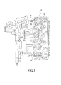
Figure 3 is a perspective schematic sectional view a fuel nozzle system; -
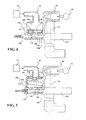
Figure 4 is schematic sectional view a fuel nozzle and having a self-purge system in one disclosed non-limiting embodiment in a first position; -
Figure 5 is a schematic view of the self-purge system ofFigure 4 in a second position; -
Figure 6 is a schematic view of a self-purge system in another disclosed non-limiting embodiment in a first position; and -
Figure 7 is a schematic view of the of self-purge system ofFigure 6 in a second position. -
Figure 1 schematically illustrates agas turbine engine 20. Thegas turbine engine 20 is disclosed herein as a two-spool turbofan that generally incorporates afan section 22, acompressor section 24, acombustor section 26 and aturbine section 28. Alternative engines might include an augmentor section (not shown) among other systems or features. Thefan section 22 drives air along a bypass flowpath while thecompressor section 24 drives air along a core flowpath for compression and communication into thecombustor section 26, then expansion through theturbine section 28. Although depicted as a turbofan gas turbine engine in the disclosed non-limiting embodiment, it should be understood that the concepts described herein are not limited to use with turbofans as the teachings may be applied to other types of turbine engines. - The
engine 20 generally includes alow spool 30 and ahigh spool 32 mounted for rotation about an engine central longitudinal axis A relative to anengine case structure 36 viaseveral bearing structures 38. Thelow spool 30 generally includes aninner shaft 40 that interconnects afan 42, a low pressure compressor ("LPC") 44 and a low pressure turbine ("LPT") 46. Theinner shaft 40 drives thefan 42 directly or through a gearedarchitecture 48 to drive thefan 42 at a lower speed than thelow spool 30. An exemplary reduction transmission is an epicyclic transmission, namely a planetary or star gear system. - The
high spool 32 includes anouter shaft 50 that interconnects a high pressure compressor ("HPC") 52 and high pressure turbine ("HPT") 54. Acombustor 56 is arranged between thehigh pressure compressor 52 and thehigh pressure turbine 54. Theinner shaft 40 and theouter shaft 50 are concentric and rotate about the engine central longitudinal axis A which is collinear with their longitudinal axes. - Core airflow is compressed by the
low pressure compressor 44, then thehigh pressure compressor 52, mixed with the fuel and burned in thecombustor 56, then expanded over the HPT 54 andLPT 46. The HPT 54 andLPT 46 rotationally drive the respectivehigh spool 32 andlow spool 30 in response to the expansion. - With reference to
Figure 2 , thecombustor 56 generally includes anouter liner 60, aninner liner 62 and adiffuser case module 64. Theouter liner 60 and theinner liner 62 are spaced apart such that acombustion chamber 66 is defined therebetween. Thecombustion chamber 66 is generally annular in shape. Theouter liner 60 and theinner liner 62 are spaced radially inward theouter diffuser case 64 to define an annularouter plenum 76 and an annularinner plenum 78. It should be understood that although a particular combustor is illustrated, other combustor types with various combustor liner arrangements will also benefit herefrom. It should be further understood that the disclosed cooling flow paths are but an illustrated embodiment and should not be limited only thereto. - The
liners turbine section 28. Eachliner respective support shell fasteners 75. - The
combustor 56 also includes a forward assembly 80 downstream of thecompressor section 24 to receive compressed airflow therefrom. The forward assembly 80 generally includes anannular hood 82, abulkhead assembly 84, a multiple of fuel nozzles 86 (one shown) and a multiple of swirlers 90 (one shown). Each swirler 90 is circumferentially aligned with one of thehood ports 94 to project through thebulkhead assembly 84. Eachbulkhead assembly 84 includes abulkhead support shell 96 secured to theliners bulkhead heat shields 98 secured to thebulkhead support shell 96. - The
annular hood 82 extends radially between, and is secured to, the forwardmost ends of theliners annular hood 82 includes a multiple of circumferentially distributedhood ports 94 that accommodate therespective fuel nozzle 86 and introduce air into the forward end of thecombustion chamber 66 through a central opening. Eachfuel nozzle 86 may be secured to thediffuser case module 64 to project through arespective hood port 94 and swirler 90. - The forward assembly 80 introduces core combustion air into the forward end of the
combustion chamber 66 while the remainder enters the annularouter plenum 76 and the annularinner plenum 78. The multiple offuel nozzles 86 and surrounding structure generate a blended fuel-air mixture that supports combustion in thecombustion chamber 66. - Opposite the forward assembly 80, the
support shells HPT 54. TheNGVs 54A are static engine components which direct core airflow combustion gases onto the turbine blades of the first turbine rotor in theHPT 54 28 to facilitate the conversion of pressure energy into kinetic energy. The combustion gases are also accelerated by theNGVs 54A because of their convergent shape and are typically given a "spin" or a "swirl" in the direction of turbine rotor rotation. - With reference to
Figure 3 , afuel nozzle system 92 generally includes one or more fuel nozzle supply manifolds 94 to which the multiple offuel nozzles 86 are connected. The fuelnozzle supply manifolds 94 are located circumferentially around thediffuser case module 64 to communicate fuel to the multiple offuel nozzles 86 to inject fuel under pressure into thecombustor 56 for ignition. It should be appreciated that thefuel nozzle systems 92 will benefit herefrom. Furthermore, fuel nozzle systems for other engine sections such as an augmentor section will also benefit herefrom. - With reference to
Figure 4 , thefuel nozzle system 92 includes one or more self-purge systems 96. The self-purge system 96 may be utilized for the entirefuel nozzle system 92, each, or subsets offuel nozzles 86, and/or for each fuel circuit of afuel nozzle 86. That is, each fuel nozzle may include primary and secondary fuel circuits that include a separate individual self-purge system 96 to provide independent purge. - Each self-
purge system 96 generally includes afirst passage 100, afirst valve 102, anaccumulator 104, asecond passage 106 and apurge valve assembly 108. It should be appreciated that although particular discrete components are schematically illustrated, the components may be combined and/or integrated directly into therespective fuel nozzle 86,fuel manifold 94 and/or thediffuser case module 64 via additive manufacturing. - The relatively complex
purge valve system 96 may be readily manufactured with an additive manufacturing process. The additive manufacturing process includes, but is not limited to, Direct Selective Laser Sintering (DSLS), Electron Beam Sintering (EBS), Electron Beam Melting (EBM), Laser Engineered Net Shaping (LENS), Laser Net Shape Manufacturing (LNSM), Direct Metal Deposition (DMD) and Laser Powder Bed Fusion (LPBF). The additive manufacturing process sequentially builds-up layers of atomized alloy and/or ceramic powder material that include but are not limited to, 625 Alloy, 718 Alloy, 230 Alloy, stainless steel, tool steel, cobalt chrome, titanium, nickel, aluminum, Waspaloy, Stellite, Titanium, Steels, Stainless Steels, Cobalt Chrome, Hastalloy X, and others. Alloys such as 625, 718 and 230 may have specific benefit for parts that operate in high temperature environments, such as, for example, environments typically encountered by aerospace and gas turbine engine components. - The
first passage 100 may be, for example, integral with amount flange 110 of thefuel nozzle 86. Theaccumulator 104 communicates with thefirst passage 100 and a pressure source such as thecompressor section 24. - The
purge valve assembly 108 communicates with thesecond passage 106 and thesecond passage 106 is in communication with thefirst passage 100. Afuel passage 112 may be within, or in communication with, therespective fuel nozzle 86, thefuel manifold 94 or a specific fuel circuit of a staged system. That is, thefuel passage 112 is representative that which is to be purged and should not be considered limited to only particular components, passages, lines, or circuits. - One disclosed non-limiting embodiment of the
purge valve assembly 108 includes avalve 120 that opens and closes aport 136 to thesecond passage 106. When the engine is in operation, compressor bleed air from thecompressor section 24 compresses aspring 132 of anaccumulator valve 134 to seal theport 136 between thesecondary passage 106 and anaccumulator volume 138. - With reference to
Figure 5 , in response to engine shut down, the compressor bleed air is reduced and thespring 132 expands such that theaccumulator valve 134 opens theport 136 into theaccumulator volume 138. Residual fuel within thefuel passage 112 is drawn into theaccumulator volume 138 to purge thefuel nozzle 86. That is, the suction from movement of theaccumulator valve 134 essentially draws the residual fuel into theaccumulator volume 138. Once theaccumulator valve 134 reaches the full open position, thevalve 102 is closed to prevent fuel backflow through theport 136. Thevalve 102 may be pneumatically, electrically, hydraulically or otherwise operated. - With reference to
Figure 6 , another disclosed non-limiting embodiment of thepurge valve assembly 108A includes adual ball valve 150 between anaccumulator 152 and thefuel passage 112. Thedual ball valve 150 includes two, one-wayball valve assemblies ball spring - When the engine is in operation, compressor bleed air flows through a
valve 166 such that an accumulator piston 172 compresses anaccumulator spring 170 in theaccumulator 152. The accumulator piston 172, sealed by abladder 168 drives residual fuel from theaccumulator 152 into thefuel nozzle 86 through the one-wayball valve assembly 150. - With reference to
Figure 7 , in response to engine shut down, the compressor bleed air is reduced and theaccumulator spring 170 expands such that the accumulator piston 172 draws residual fuel from within thefuel nozzle 86 into theaccumulator 152 though the one-wayball valve assembly 156. Once thebladder 168 reaches the full open position, thedual ball valve 150 closes under spring force to prevent fuel backflow. - It should be understood that relative positional terms such as "forward," "aft," "upper," "lower," "above," "below," and the like are with reference to the normal operational attitude and should not be considered otherwise limiting.
- It should be understood that like reference numerals identify corresponding or similar elements throughout the several drawings. It should also be understood that although a particular component arrangement is disclosed in the illustrated embodiment, other arrangements will benefit herefrom.
- Although particular step sequences are shown, described, and claimed, it should be understood that steps may be performed in any order, separated or combined unless otherwise indicated and will still benefit from the present disclosure.
- The foregoing description is exemplary rather than defined by the limitations within. Various non-limiting embodiments are disclosed herein, however, one of ordinary skill in the art would recognize that various modifications and variations in light of the above teachings will fall within the scope of the appended claims. It is therefore to be understood that within the scope of the appended claims, the disclosure may be practiced other than as specifically described. For that reason the appended claims should be studied to determine true scope and content.
Claims (15)
- A self-purge system (96), comprising:an additively manufactured purge valve assembly (108; 108A) in communication with a fuel passage (112) to selectively purge said fuel passage (112).
- The self-purge system as recited in claim 1, wherein said fuel passage (112) is in communication with a fuel nozzle (86).
- The self-purge system as recited in claim 1 or 2, wherein said fuel passage (112) is a portion of a fuel manifold (94).
- The self-purge system as recited in any preceding claim, wherein said fuel passage (112) is a fuel circuit of a fuel nozzle (86).
- The self-purge system as recited in any preceding claim, wherein said additively manufactured purge valve assembly (108; 108A) is in communication with an accumulator volume (138) and a pressure source (24).
- The self-purge system as recited in claim 5, wherein said accumulator volume (138) contains an accumulator piston with a valve (120).
- The self-purge system as recited in claim 6, further comprising a spring (132) that biases said accumulator piston.
- The self-purge system as recited in claim 7, wherein said accumulator piston operates in response to pressure source (24) and said spring (132).
- The self-purge system as recited in claim 6, 7 or 8, further comprising a backflow valve (102) in communication with said fuel passage (112).
- The self-purge system as recited in claim 5, wherein said additively manufactured purge valve assembly includes a dual ball valve (150).
- The self-purge system as recited in claim 10, wherein said dual ball valve (150) includes two, one-way ball valve assemblies (154, 156).
- The self-purge system as recited in claim 11, further comprising a spring (170) that biases an accumulator piston (172), said accumulator piston (172) in communication with said additively manufactured purge valve assembly (108A).
- The self-purge system as recited in claim 12, wherein said accumulator piston (172) is sealed by a bladder seal (168).
- The self-purge system as recited in claim 13, further comprising a bleed air valve (166) in communication with said bladder seal (168).
- A fuel nozzle system of a gas turbine engine, comprising:a fuel nozzle (86); anda self-purge system (96) as recited in any preceding claim, in communication with a fuel passage of said fuel nozzle.
Applications Claiming Priority (1)
| Application Number | Priority Date | Filing Date | Title |
|---|---|---|---|
| US201462026127P | 2014-07-18 | 2014-07-18 |
Publications (2)
| Publication Number | Publication Date |
|---|---|
| EP2975240A1 true EP2975240A1 (en) | 2016-01-20 |
| EP2975240B1 EP2975240B1 (en) | 2019-11-13 |
Family
ID=53835235
Family Applications (1)
| Application Number | Title | Priority Date | Filing Date |
|---|---|---|---|
| EP15177397.5A Active EP2975240B1 (en) | 2014-07-18 | 2015-07-17 | Self-purging fuel nozzle system for a gas turbine engine |
Country Status (2)
| Country | Link |
|---|---|
| US (1) | US9909500B2 (en) |
| EP (1) | EP2975240B1 (en) |
Cited By (2)
| Publication number | Priority date | Publication date | Assignee | Title |
|---|---|---|---|---|
| EP3203053A1 (en) * | 2016-02-02 | 2017-08-09 | Rolls-Royce plc | Gas turbine engine fuel system |
| CN107553903A (en) * | 2017-10-31 | 2018-01-09 | 王俊铎 | An improved 3D printing device |
Families Citing this family (5)
| Publication number | Priority date | Publication date | Assignee | Title |
|---|---|---|---|---|
| US10739006B2 (en) | 2017-03-15 | 2020-08-11 | General Electric Company | Fuel nozzle for a gas turbine engine |
| US10775048B2 (en) | 2017-03-15 | 2020-09-15 | General Electric Company | Fuel nozzle for a gas turbine engine |
| US20220213765A1 (en) * | 2019-04-05 | 2022-07-07 | Schlumberger Technology Corporation | Elevated erosion resistant manifold |
| US11592177B2 (en) | 2021-04-16 | 2023-02-28 | General Electric Company | Purging configuration for combustor mixing assembly |
| US11542870B1 (en) | 2021-11-24 | 2023-01-03 | General Electric Company | Gas supply system |
Citations (3)
| Publication number | Priority date | Publication date | Assignee | Title |
|---|---|---|---|---|
| US3774851A (en) * | 1972-11-15 | 1973-11-27 | Parker Hannifin Corp | Fuel head compensating valve for fuel injection nozzle |
| US20130000318A1 (en) * | 2011-06-28 | 2013-01-03 | Goodrich Pump & Engine Control Systems, Inc. | Ecology system for draining the manifold of a gas turbine engine |
| EP2754516A2 (en) * | 2013-01-15 | 2014-07-16 | Honeywell International Inc. | Spring assemblies for use in gas turbine engines and methods for their manufacture |
Family Cites Families (16)
| Publication number | Priority date | Publication date | Assignee | Title |
|---|---|---|---|---|
| AU1936099A (en) | 1997-12-20 | 1999-07-12 | Allied-Signal Inc. | Peak compressor bleed pressure storage for extended fuel nozzle purging of a microturbine power generating system |
| DE59810159D1 (en) | 1998-02-26 | 2003-12-18 | Alstom Switzerland Ltd | Method for safely removing liquid fuel from the fuel system of a gas turbine and device for carrying out the method |
| JP3883025B2 (en) | 1998-03-26 | 2007-02-21 | ヤマハマリン株式会社 | In-cylinder fuel injection engine |
| US6630244B1 (en) | 2001-03-23 | 2003-10-07 | Delavan Inc. | Carbon resistant surface coating |
| US6675583B2 (en) | 2000-10-04 | 2004-01-13 | Capstone Turbine Corporation | Combustion method |
| FR2871519B1 (en) | 2004-06-10 | 2006-08-04 | Snecma Moteurs Sa | METHOD AND SYSTEM FOR PROTECTING GAS TURBINE FUEL INJECTORS |
| US7213394B2 (en) | 2005-01-27 | 2007-05-08 | Cummins Inc. | Engine blowby injector and injection system and method for injecting blowby |
| US7677025B2 (en) | 2005-02-01 | 2010-03-16 | Power Systems Mfg., Llc | Self-purging pilot fuel injection system |
| GB0502438D0 (en) | 2005-02-05 | 2005-03-16 | Alstom Technology Ltd | Fuel injection system and method of monitoring purging of the same |
| US7559201B2 (en) | 2005-09-08 | 2009-07-14 | Pratt & Whitney Canada Corp. | Redundant fuel manifold sealing arrangement |
| US8006482B2 (en) | 2007-03-02 | 2011-08-30 | Caterpillar Inc. | Method of purging fluid injector by heating |
| US7958721B2 (en) | 2007-06-29 | 2011-06-14 | Caterpillar Inc. | Regeneration system having integral purge and ignition device |
| US8340886B2 (en) | 2011-03-07 | 2012-12-25 | General Electric Company | System and method for transitioning between fuel supplies for a combustion system |
| DE102012018649A1 (en) * | 2012-09-20 | 2014-03-20 | Liebherr-Aerospace Lindenberg Gmbh | Klappenaktuator |
| US9272437B2 (en) * | 2012-10-31 | 2016-03-01 | Flow International Corporation | Fluid distribution components of high-pressure fluid jet systems |
| US20160186620A1 (en) * | 2014-12-30 | 2016-06-30 | General Electric Company | Multi-material valve guide system and method |
-
2015
- 2015-07-17 EP EP15177397.5A patent/EP2975240B1/en active Active
- 2015-07-17 US US14/801,927 patent/US9909500B2/en active Active
Patent Citations (3)
| Publication number | Priority date | Publication date | Assignee | Title |
|---|---|---|---|---|
| US3774851A (en) * | 1972-11-15 | 1973-11-27 | Parker Hannifin Corp | Fuel head compensating valve for fuel injection nozzle |
| US20130000318A1 (en) * | 2011-06-28 | 2013-01-03 | Goodrich Pump & Engine Control Systems, Inc. | Ecology system for draining the manifold of a gas turbine engine |
| EP2754516A2 (en) * | 2013-01-15 | 2014-07-16 | Honeywell International Inc. | Spring assemblies for use in gas turbine engines and methods for their manufacture |
Cited By (3)
| Publication number | Priority date | Publication date | Assignee | Title |
|---|---|---|---|---|
| EP3203053A1 (en) * | 2016-02-02 | 2017-08-09 | Rolls-Royce plc | Gas turbine engine fuel system |
| US10563588B2 (en) | 2016-02-02 | 2020-02-18 | Rolls-Royce Plc | Fuel system with vacuum generator to purge fuel from fuel nozzles |
| CN107553903A (en) * | 2017-10-31 | 2018-01-09 | 王俊铎 | An improved 3D printing device |
Also Published As
| Publication number | Publication date |
|---|---|
| US20160017809A1 (en) | 2016-01-21 |
| EP2975240B1 (en) | 2019-11-13 |
| US9909500B2 (en) | 2018-03-06 |
Similar Documents
| Publication | Publication Date | Title |
|---|---|---|
| EP2975240B1 (en) | Self-purging fuel nozzle system for a gas turbine engine | |
| EP3033508B1 (en) | Cooled fuel injector system for a gas turbine engine | |
| US10107497B2 (en) | Gas turbine engine combustor liner | |
| US10101031B2 (en) | Swirler mount interface for gas turbine engine combustor | |
| US9964307B2 (en) | Interface heat shield for a combustor of a gas turbine engine | |
| US10436449B2 (en) | Light weight swirler for gas turbine engine combustor and a method for lightening a swirler for a gas turbine engine | |
| EP2966357B1 (en) | Fuel injector and swirler for a gas turbine | |
| EP2901082B1 (en) | Inner diffuser case struts for a combustor of a gas turbine engine | |
| EP3404330A1 (en) | Redundant endrail for combustor panel | |
| US11226102B2 (en) | Fuel nozzle for a gas turbine engine | |
| US20180128488A1 (en) | Fuel nozzle assembly with impingement purge | |
| EP2959132B1 (en) | Self-purging fuel injector system for a gas turbine engine |
Legal Events
| Date | Code | Title | Description |
|---|---|---|---|
| PUAI | Public reference made under article 153(3) epc to a published international application that has entered the european phase |
Free format text: ORIGINAL CODE: 0009012 |
|
| AK | Designated contracting states |
Kind code of ref document: A1 Designated state(s): AL AT BE BG CH CY CZ DE DK EE ES FI FR GB GR HR HU IE IS IT LI LT LU LV MC MK MT NL NO PL PT RO RS SE SI SK SM TR |
|
| AX | Request for extension of the european patent |
Extension state: BA ME |
|
| 17P | Request for examination filed |
Effective date: 20160720 |
|
| RBV | Designated contracting states (corrected) |
Designated state(s): AL AT BE BG CH CY CZ DE DK EE ES FI FR GB GR HR HU IE IS IT LI LT LU LV MC MK MT NL NO PL PT RO RS SE SI SK SM TR |
|
| RAP1 | Party data changed (applicant data changed or rights of an application transferred) |
Owner name: UNITED TECHNOLOGIES CORPORATION |
|
| GRAP | Despatch of communication of intention to grant a patent |
Free format text: ORIGINAL CODE: EPIDOSNIGR1 |
|
| STAA | Information on the status of an ep patent application or granted ep patent |
Free format text: STATUS: GRANT OF PATENT IS INTENDED |
|
| INTG | Intention to grant announced |
Effective date: 20190523 |
|
| GRAS | Grant fee paid |
Free format text: ORIGINAL CODE: EPIDOSNIGR3 |
|
| GRAA | (expected) grant |
Free format text: ORIGINAL CODE: 0009210 |
|
| STAA | Information on the status of an ep patent application or granted ep patent |
Free format text: STATUS: THE PATENT HAS BEEN GRANTED |
|
| AK | Designated contracting states |
Kind code of ref document: B1 Designated state(s): AL AT BE BG CH CY CZ DE DK EE ES FI FR GB GR HR HU IE IS IT LI LT LU LV MC MK MT NL NO PL PT RO RS SE SI SK SM TR |
|
| REG | Reference to a national code |
Ref country code: CH Ref legal event code: EP Ref country code: AT Ref legal event code: REF Ref document number: 1201893 Country of ref document: AT Kind code of ref document: T Effective date: 20191115 |
|
| REG | Reference to a national code |
Ref country code: DE Ref legal event code: R096 Ref document number: 602015041511 Country of ref document: DE |
|
| REG | Reference to a national code |
Ref country code: IE Ref legal event code: FG4D |
|
| REG | Reference to a national code |
Ref country code: NL Ref legal event code: MP Effective date: 20191113 |
|
| REG | Reference to a national code |
Ref country code: LT Ref legal event code: MG4D |
|
| PG25 | Lapsed in a contracting state [announced via postgrant information from national office to epo] |
Ref country code: BG Free format text: LAPSE BECAUSE OF FAILURE TO SUBMIT A TRANSLATION OF THE DESCRIPTION OR TO PAY THE FEE WITHIN THE PRESCRIBED TIME-LIMIT Effective date: 20200213 Ref country code: PT Free format text: LAPSE BECAUSE OF FAILURE TO SUBMIT A TRANSLATION OF THE DESCRIPTION OR TO PAY THE FEE WITHIN THE PRESCRIBED TIME-LIMIT Effective date: 20200313 Ref country code: FI Free format text: LAPSE BECAUSE OF FAILURE TO SUBMIT A TRANSLATION OF THE DESCRIPTION OR TO PAY THE FEE WITHIN THE PRESCRIBED TIME-LIMIT Effective date: 20191113 Ref country code: NL Free format text: LAPSE BECAUSE OF FAILURE TO SUBMIT A TRANSLATION OF THE DESCRIPTION OR TO PAY THE FEE WITHIN THE PRESCRIBED TIME-LIMIT Effective date: 20191113 Ref country code: LV Free format text: LAPSE BECAUSE OF FAILURE TO SUBMIT A TRANSLATION OF THE DESCRIPTION OR TO PAY THE FEE WITHIN THE PRESCRIBED TIME-LIMIT Effective date: 20191113 Ref country code: SE Free format text: LAPSE BECAUSE OF FAILURE TO SUBMIT A TRANSLATION OF THE DESCRIPTION OR TO PAY THE FEE WITHIN THE PRESCRIBED TIME-LIMIT Effective date: 20191113 Ref country code: PL Free format text: LAPSE BECAUSE OF FAILURE TO SUBMIT A TRANSLATION OF THE DESCRIPTION OR TO PAY THE FEE WITHIN THE PRESCRIBED TIME-LIMIT Effective date: 20191113 Ref country code: NO Free format text: LAPSE BECAUSE OF FAILURE TO SUBMIT A TRANSLATION OF THE DESCRIPTION OR TO PAY THE FEE WITHIN THE PRESCRIBED TIME-LIMIT Effective date: 20200213 Ref country code: GR Free format text: LAPSE BECAUSE OF FAILURE TO SUBMIT A TRANSLATION OF THE DESCRIPTION OR TO PAY THE FEE WITHIN THE PRESCRIBED TIME-LIMIT Effective date: 20200214 Ref country code: LT Free format text: LAPSE BECAUSE OF FAILURE TO SUBMIT A TRANSLATION OF THE DESCRIPTION OR TO PAY THE FEE WITHIN THE PRESCRIBED TIME-LIMIT Effective date: 20191113 |
|
| PG25 | Lapsed in a contracting state [announced via postgrant information from national office to epo] |
Ref country code: IS Free format text: LAPSE BECAUSE OF FAILURE TO SUBMIT A TRANSLATION OF THE DESCRIPTION OR TO PAY THE FEE WITHIN THE PRESCRIBED TIME-LIMIT Effective date: 20200313 Ref country code: HR Free format text: LAPSE BECAUSE OF FAILURE TO SUBMIT A TRANSLATION OF THE DESCRIPTION OR TO PAY THE FEE WITHIN THE PRESCRIBED TIME-LIMIT Effective date: 20191113 Ref country code: RS Free format text: LAPSE BECAUSE OF FAILURE TO SUBMIT A TRANSLATION OF THE DESCRIPTION OR TO PAY THE FEE WITHIN THE PRESCRIBED TIME-LIMIT Effective date: 20191113 |
|
| PG25 | Lapsed in a contracting state [announced via postgrant information from national office to epo] |
Ref country code: AL Free format text: LAPSE BECAUSE OF FAILURE TO SUBMIT A TRANSLATION OF THE DESCRIPTION OR TO PAY THE FEE WITHIN THE PRESCRIBED TIME-LIMIT Effective date: 20191113 |
|
| PG25 | Lapsed in a contracting state [announced via postgrant information from national office to epo] |
Ref country code: EE Free format text: LAPSE BECAUSE OF FAILURE TO SUBMIT A TRANSLATION OF THE DESCRIPTION OR TO PAY THE FEE WITHIN THE PRESCRIBED TIME-LIMIT Effective date: 20191113 Ref country code: DK Free format text: LAPSE BECAUSE OF FAILURE TO SUBMIT A TRANSLATION OF THE DESCRIPTION OR TO PAY THE FEE WITHIN THE PRESCRIBED TIME-LIMIT Effective date: 20191113 Ref country code: ES Free format text: LAPSE BECAUSE OF FAILURE TO SUBMIT A TRANSLATION OF THE DESCRIPTION OR TO PAY THE FEE WITHIN THE PRESCRIBED TIME-LIMIT Effective date: 20191113 Ref country code: RO Free format text: LAPSE BECAUSE OF FAILURE TO SUBMIT A TRANSLATION OF THE DESCRIPTION OR TO PAY THE FEE WITHIN THE PRESCRIBED TIME-LIMIT Effective date: 20191113 Ref country code: CZ Free format text: LAPSE BECAUSE OF FAILURE TO SUBMIT A TRANSLATION OF THE DESCRIPTION OR TO PAY THE FEE WITHIN THE PRESCRIBED TIME-LIMIT Effective date: 20191113 |
|
| REG | Reference to a national code |
Ref country code: DE Ref legal event code: R097 Ref document number: 602015041511 Country of ref document: DE |
|
| REG | Reference to a national code |
Ref country code: AT Ref legal event code: MK05 Ref document number: 1201893 Country of ref document: AT Kind code of ref document: T Effective date: 20191113 |
|
| PG25 | Lapsed in a contracting state [announced via postgrant information from national office to epo] |
Ref country code: SM Free format text: LAPSE BECAUSE OF FAILURE TO SUBMIT A TRANSLATION OF THE DESCRIPTION OR TO PAY THE FEE WITHIN THE PRESCRIBED TIME-LIMIT Effective date: 20191113 Ref country code: SK Free format text: LAPSE BECAUSE OF FAILURE TO SUBMIT A TRANSLATION OF THE DESCRIPTION OR TO PAY THE FEE WITHIN THE PRESCRIBED TIME-LIMIT Effective date: 20191113 |
|
| PLBE | No opposition filed within time limit |
Free format text: ORIGINAL CODE: 0009261 |
|
| STAA | Information on the status of an ep patent application or granted ep patent |
Free format text: STATUS: NO OPPOSITION FILED WITHIN TIME LIMIT |
|
| 26N | No opposition filed |
Effective date: 20200814 |
|
| PG25 | Lapsed in a contracting state [announced via postgrant information from national office to epo] |
Ref country code: AT Free format text: LAPSE BECAUSE OF FAILURE TO SUBMIT A TRANSLATION OF THE DESCRIPTION OR TO PAY THE FEE WITHIN THE PRESCRIBED TIME-LIMIT Effective date: 20191113 Ref country code: SI Free format text: LAPSE BECAUSE OF FAILURE TO SUBMIT A TRANSLATION OF THE DESCRIPTION OR TO PAY THE FEE WITHIN THE PRESCRIBED TIME-LIMIT Effective date: 20191113 |
|
| PG25 | Lapsed in a contracting state [announced via postgrant information from national office to epo] |
Ref country code: IT Free format text: LAPSE BECAUSE OF FAILURE TO SUBMIT A TRANSLATION OF THE DESCRIPTION OR TO PAY THE FEE WITHIN THE PRESCRIBED TIME-LIMIT Effective date: 20191113 |
|
| PG25 | Lapsed in a contracting state [announced via postgrant information from national office to epo] |
Ref country code: MC Free format text: LAPSE BECAUSE OF FAILURE TO SUBMIT A TRANSLATION OF THE DESCRIPTION OR TO PAY THE FEE WITHIN THE PRESCRIBED TIME-LIMIT Effective date: 20191113 |
|
| REG | Reference to a national code |
Ref country code: CH Ref legal event code: PL |
|
| REG | Reference to a national code |
Ref country code: BE Ref legal event code: MM Effective date: 20200731 |
|
| PG25 | Lapsed in a contracting state [announced via postgrant information from national office to epo] |
Ref country code: LU Free format text: LAPSE BECAUSE OF NON-PAYMENT OF DUE FEES Effective date: 20200717 Ref country code: LI Free format text: LAPSE BECAUSE OF NON-PAYMENT OF DUE FEES Effective date: 20200731 Ref country code: CH Free format text: LAPSE BECAUSE OF NON-PAYMENT OF DUE FEES Effective date: 20200731 |
|
| PG25 | Lapsed in a contracting state [announced via postgrant information from national office to epo] |
Ref country code: BE Free format text: LAPSE BECAUSE OF NON-PAYMENT OF DUE FEES Effective date: 20200731 |
|
| PG25 | Lapsed in a contracting state [announced via postgrant information from national office to epo] |
Ref country code: IE Free format text: LAPSE BECAUSE OF NON-PAYMENT OF DUE FEES Effective date: 20200717 |
|
| PG25 | Lapsed in a contracting state [announced via postgrant information from national office to epo] |
Ref country code: TR Free format text: LAPSE BECAUSE OF FAILURE TO SUBMIT A TRANSLATION OF THE DESCRIPTION OR TO PAY THE FEE WITHIN THE PRESCRIBED TIME-LIMIT Effective date: 20191113 Ref country code: MT Free format text: LAPSE BECAUSE OF FAILURE TO SUBMIT A TRANSLATION OF THE DESCRIPTION OR TO PAY THE FEE WITHIN THE PRESCRIBED TIME-LIMIT Effective date: 20191113 Ref country code: CY Free format text: LAPSE BECAUSE OF FAILURE TO SUBMIT A TRANSLATION OF THE DESCRIPTION OR TO PAY THE FEE WITHIN THE PRESCRIBED TIME-LIMIT Effective date: 20191113 |
|
| PG25 | Lapsed in a contracting state [announced via postgrant information from national office to epo] |
Ref country code: MK Free format text: LAPSE BECAUSE OF FAILURE TO SUBMIT A TRANSLATION OF THE DESCRIPTION OR TO PAY THE FEE WITHIN THE PRESCRIBED TIME-LIMIT Effective date: 20191113 |
|
| REG | Reference to a national code |
Ref country code: DE Ref legal event code: R081 Ref document number: 602015041511 Country of ref document: DE Owner name: RAYTHEON TECHNOLOGIES CORPORATION (N.D.GES.D.S, US Free format text: FORMER OWNER: UNITED TECHNOLOGIES CORPORATION, FARMINGTON, CONN., US Ref country code: DE Ref legal event code: R081 Ref document number: 602015041511 Country of ref document: DE Owner name: RTX CORPORATION (N.D.GES.D. STAATES DELAWARE),, US Free format text: FORMER OWNER: UNITED TECHNOLOGIES CORPORATION, FARMINGTON, CONN., US |
|
| P01 | Opt-out of the competence of the unified patent court (upc) registered |
Effective date: 20230520 |
|
| PGFP | Annual fee paid to national office [announced via postgrant information from national office to epo] |
Ref country code: GB Payment date: 20250619 Year of fee payment: 11 |
|
| PGFP | Annual fee paid to national office [announced via postgrant information from national office to epo] |
Ref country code: FR Payment date: 20250619 Year of fee payment: 11 |
|
| PGFP | Annual fee paid to national office [announced via postgrant information from national office to epo] |
Ref country code: DE Payment date: 20250620 Year of fee payment: 11 |
|
| REG | Reference to a national code |
Ref country code: DE Ref legal event code: R081 Ref document number: 602015041511 Country of ref document: DE Owner name: RTX CORPORATION (N.D.GES.D. STAATES DELAWARE),, US Free format text: FORMER OWNER: RAYTHEON TECHNOLOGIES CORPORATION (N.D.GES.D.STAATES DELAWARE), ARLINGTON, VA, US |