EP2975215A1 - Method of creating heat transfer features in high temperature alloys - Google Patents
Method of creating heat transfer features in high temperature alloys Download PDFInfo
- Publication number
- EP2975215A1 EP2975215A1 EP15176864.5A EP15176864A EP2975215A1 EP 2975215 A1 EP2975215 A1 EP 2975215A1 EP 15176864 A EP15176864 A EP 15176864A EP 2975215 A1 EP2975215 A1 EP 2975215A1
- Authority
- EP
- European Patent Office
- Prior art keywords
- portions
- high temperature
- heat transfer
- component
- alloy material
- Prior art date
- Legal status (The legal status is an assumption and is not a legal conclusion. Google has not performed a legal analysis and makes no representation as to the accuracy of the status listed.)
- Withdrawn
Links
Images


Classifications
-
- B—PERFORMING OPERATIONS; TRANSPORTING
- B23—MACHINE TOOLS; METAL-WORKING NOT OTHERWISE PROVIDED FOR
- B23P—METAL-WORKING NOT OTHERWISE PROVIDED FOR; COMBINED OPERATIONS; UNIVERSAL MACHINE TOOLS
- B23P15/00—Making specific metal objects by operations not covered by a single other subclass or a group in this subclass
- B23P15/04—Making specific metal objects by operations not covered by a single other subclass or a group in this subclass turbine or like blades from several pieces
-
- F—MECHANICAL ENGINEERING; LIGHTING; HEATING; WEAPONS; BLASTING
- F01—MACHINES OR ENGINES IN GENERAL; ENGINE PLANTS IN GENERAL; STEAM ENGINES
- F01D—NON-POSITIVE DISPLACEMENT MACHINES OR ENGINES, e.g. STEAM TURBINES
- F01D25/00—Component parts, details, or accessories, not provided for in, or of interest apart from, other groups
- F01D25/08—Cooling; Heating; Heat-insulation
- F01D25/12—Cooling
-
- F—MECHANICAL ENGINEERING; LIGHTING; HEATING; WEAPONS; BLASTING
- F01—MACHINES OR ENGINES IN GENERAL; ENGINE PLANTS IN GENERAL; STEAM ENGINES
- F01D—NON-POSITIVE DISPLACEMENT MACHINES OR ENGINES, e.g. STEAM TURBINES
- F01D11/00—Preventing or minimising internal leakage of working-fluid, e.g. between stages
- F01D11/08—Preventing or minimising internal leakage of working-fluid, e.g. between stages for sealing space between rotor blade tips and stator
- F01D11/10—Preventing or minimising internal leakage of working-fluid, e.g. between stages for sealing space between rotor blade tips and stator using sealing fluid, e.g. steam
-
- F—MECHANICAL ENGINEERING; LIGHTING; HEATING; WEAPONS; BLASTING
- F01—MACHINES OR ENGINES IN GENERAL; ENGINE PLANTS IN GENERAL; STEAM ENGINES
- F01D—NON-POSITIVE DISPLACEMENT MACHINES OR ENGINES, e.g. STEAM TURBINES
- F01D25/00—Component parts, details, or accessories, not provided for in, or of interest apart from, other groups
- F01D25/005—Selecting particular materials
-
- F—MECHANICAL ENGINEERING; LIGHTING; HEATING; WEAPONS; BLASTING
- F01—MACHINES OR ENGINES IN GENERAL; ENGINE PLANTS IN GENERAL; STEAM ENGINES
- F01D—NON-POSITIVE DISPLACEMENT MACHINES OR ENGINES, e.g. STEAM TURBINES
- F01D25/00—Component parts, details, or accessories, not provided for in, or of interest apart from, other groups
- F01D25/28—Supporting or mounting arrangements, e.g. for turbine casing
-
- F—MECHANICAL ENGINEERING; LIGHTING; HEATING; WEAPONS; BLASTING
- F01—MACHINES OR ENGINES IN GENERAL; ENGINE PLANTS IN GENERAL; STEAM ENGINES
- F01D—NON-POSITIVE DISPLACEMENT MACHINES OR ENGINES, e.g. STEAM TURBINES
- F01D5/00—Blades; Blade-carrying members; Heating, heat-insulating, cooling or antivibration means on the blades or the members
- F01D5/12—Blades
- F01D5/14—Form or construction
- F01D5/147—Construction, i.e. structural features, e.g. of weight-saving hollow blades
-
- F—MECHANICAL ENGINEERING; LIGHTING; HEATING; WEAPONS; BLASTING
- F01—MACHINES OR ENGINES IN GENERAL; ENGINE PLANTS IN GENERAL; STEAM ENGINES
- F01D—NON-POSITIVE DISPLACEMENT MACHINES OR ENGINES, e.g. STEAM TURBINES
- F01D5/00—Blades; Blade-carrying members; Heating, heat-insulating, cooling or antivibration means on the blades or the members
- F01D5/12—Blades
- F01D5/14—Form or construction
- F01D5/18—Hollow blades, i.e. blades with cooling or heating channels or cavities; Heating, heat-insulating or cooling means on blades
- F01D5/186—Film cooling
-
- F—MECHANICAL ENGINEERING; LIGHTING; HEATING; WEAPONS; BLASTING
- F01—MACHINES OR ENGINES IN GENERAL; ENGINE PLANTS IN GENERAL; STEAM ENGINES
- F01D—NON-POSITIVE DISPLACEMENT MACHINES OR ENGINES, e.g. STEAM TURBINES
- F01D9/00—Stators
- F01D9/02—Nozzles; Nozzle boxes; Stator blades; Guide conduits, e.g. individual nozzles
- F01D9/04—Nozzles; Nozzle boxes; Stator blades; Guide conduits, e.g. individual nozzles forming ring or sector
-
- F—MECHANICAL ENGINEERING; LIGHTING; HEATING; WEAPONS; BLASTING
- F01—MACHINES OR ENGINES IN GENERAL; ENGINE PLANTS IN GENERAL; STEAM ENGINES
- F01D—NON-POSITIVE DISPLACEMENT MACHINES OR ENGINES, e.g. STEAM TURBINES
- F01D9/00—Stators
- F01D9/02—Nozzles; Nozzle boxes; Stator blades; Guide conduits, e.g. individual nozzles
- F01D9/04—Nozzles; Nozzle boxes; Stator blades; Guide conduits, e.g. individual nozzles forming ring or sector
- F01D9/041—Nozzles; Nozzle boxes; Stator blades; Guide conduits, e.g. individual nozzles forming ring or sector using blades
-
- F—MECHANICAL ENGINEERING; LIGHTING; HEATING; WEAPONS; BLASTING
- F01—MACHINES OR ENGINES IN GENERAL; ENGINE PLANTS IN GENERAL; STEAM ENGINES
- F01D—NON-POSITIVE DISPLACEMENT MACHINES OR ENGINES, e.g. STEAM TURBINES
- F01D9/00—Stators
- F01D9/06—Fluid supply conduits to nozzles or the like
- F01D9/065—Fluid supply or removal conduits traversing the working fluid flow, e.g. for lubrication-, cooling-, or sealing fluids
-
- F—MECHANICAL ENGINEERING; LIGHTING; HEATING; WEAPONS; BLASTING
- F23—COMBUSTION APPARATUS; COMBUSTION PROCESSES
- F23R—GENERATING COMBUSTION PRODUCTS OF HIGH PRESSURE OR HIGH VELOCITY, e.g. GAS-TURBINE COMBUSTION CHAMBERS
- F23R3/00—Continuous combustion chambers using liquid or gaseous fuel
- F23R3/002—Wall structures
-
- F—MECHANICAL ENGINEERING; LIGHTING; HEATING; WEAPONS; BLASTING
- F05—INDEXING SCHEMES RELATING TO ENGINES OR PUMPS IN VARIOUS SUBCLASSES OF CLASSES F01-F04
- F05D—INDEXING SCHEME FOR ASPECTS RELATING TO NON-POSITIVE-DISPLACEMENT MACHINES OR ENGINES, GAS-TURBINES OR JET-PROPULSION PLANTS
- F05D2220/00—Application
- F05D2220/30—Application in turbines
- F05D2220/32—Application in turbines in gas turbines
-
- F—MECHANICAL ENGINEERING; LIGHTING; HEATING; WEAPONS; BLASTING
- F05—INDEXING SCHEMES RELATING TO ENGINES OR PUMPS IN VARIOUS SUBCLASSES OF CLASSES F01-F04
- F05D—INDEXING SCHEME FOR ASPECTS RELATING TO NON-POSITIVE-DISPLACEMENT MACHINES OR ENGINES, GAS-TURBINES OR JET-PROPULSION PLANTS
- F05D2230/00—Manufacture
- F05D2230/20—Manufacture essentially without removing material
- F05D2230/23—Manufacture essentially without removing material by permanently joining parts together
- F05D2230/232—Manufacture essentially without removing material by permanently joining parts together by welding
- F05D2230/236—Diffusion bonding
-
- F—MECHANICAL ENGINEERING; LIGHTING; HEATING; WEAPONS; BLASTING
- F05—INDEXING SCHEMES RELATING TO ENGINES OR PUMPS IN VARIOUS SUBCLASSES OF CLASSES F01-F04
- F05D—INDEXING SCHEME FOR ASPECTS RELATING TO NON-POSITIVE-DISPLACEMENT MACHINES OR ENGINES, GAS-TURBINES OR JET-PROPULSION PLANTS
- F05D2230/00—Manufacture
- F05D2230/60—Assembly methods
-
- F—MECHANICAL ENGINEERING; LIGHTING; HEATING; WEAPONS; BLASTING
- F05—INDEXING SCHEMES RELATING TO ENGINES OR PUMPS IN VARIOUS SUBCLASSES OF CLASSES F01-F04
- F05D—INDEXING SCHEME FOR ASPECTS RELATING TO NON-POSITIVE-DISPLACEMENT MACHINES OR ENGINES, GAS-TURBINES OR JET-PROPULSION PLANTS
- F05D2260/00—Function
- F05D2260/20—Heat transfer, e.g. cooling
- F05D2260/202—Heat transfer, e.g. cooling by film cooling
-
- F—MECHANICAL ENGINEERING; LIGHTING; HEATING; WEAPONS; BLASTING
- F05—INDEXING SCHEMES RELATING TO ENGINES OR PUMPS IN VARIOUS SUBCLASSES OF CLASSES F01-F04
- F05D—INDEXING SCHEME FOR ASPECTS RELATING TO NON-POSITIVE-DISPLACEMENT MACHINES OR ENGINES, GAS-TURBINES OR JET-PROPULSION PLANTS
- F05D2260/00—Function
- F05D2260/20—Heat transfer, e.g. cooling
- F05D2260/221—Improvement of heat transfer
-
- F—MECHANICAL ENGINEERING; LIGHTING; HEATING; WEAPONS; BLASTING
- F05—INDEXING SCHEMES RELATING TO ENGINES OR PUMPS IN VARIOUS SUBCLASSES OF CLASSES F01-F04
- F05D—INDEXING SCHEME FOR ASPECTS RELATING TO NON-POSITIVE-DISPLACEMENT MACHINES OR ENGINES, GAS-TURBINES OR JET-PROPULSION PLANTS
- F05D2300/00—Materials; Properties thereof
- F05D2300/10—Metals, alloys or intermetallic compounds
- F05D2300/13—Refractory metals, i.e. Ti, V, Cr, Zr, Nb, Mo, Hf, Ta, W
- F05D2300/131—Molybdenum
-
- Y—GENERAL TAGGING OF NEW TECHNOLOGICAL DEVELOPMENTS; GENERAL TAGGING OF CROSS-SECTIONAL TECHNOLOGIES SPANNING OVER SEVERAL SECTIONS OF THE IPC; TECHNICAL SUBJECTS COVERED BY FORMER USPC CROSS-REFERENCE ART COLLECTIONS [XRACs] AND DIGESTS
- Y02—TECHNOLOGIES OR APPLICATIONS FOR MITIGATION OR ADAPTATION AGAINST CLIMATE CHANGE
- Y02T—CLIMATE CHANGE MITIGATION TECHNOLOGIES RELATED TO TRANSPORTATION
- Y02T50/00—Aeronautics or air transport
- Y02T50/60—Efficient propulsion technologies, e.g. for aircraft
Definitions
- airfoils for rotating blades and stator vanes are made from materials that can withstand higher operating temperatures, such as high temperature alloys.
- internal cooling passages are formed within the airfoils.
- the internal cooling passages in some nickel alloy airfoils have been configured to include heat transfer treatments such as trip strips formed on passage walls.
- a method for forming a gas turbine engine component comprises the steps of forming a first portion from a high temperature alloy material, and forming a second portion from the high temperature alloy material, the first and second portions each defining an external surface and an internal surface. At least one heat transfer feature is formed directly on the internal surface of at least one of the first and second portions. The first and second portions are attached together to form a component.
- the high temperature alloy material can withstand operating temperatures within a range of 2200-2700 degrees Fahrenheit (1316-1482°C).
- the high temperature alloy material includes molybdenum, and the high temperature material is comprised of an alloy having greater than 90% molybdenum by weight.
- forming a first portion from a high temperature alloy material includes forging a block comprised of the high temperature alloy material and cutting the block into the first portion and the second portion.
- Another embodiment according to any of the previous embodiments includes machining the external surfaces of the first and second portions subsequent to attaching the first and second portions together to form a component to provide a finished component.
- attaching the first and second portions together to form a component to provide a finished component includes diffusion bonding the first and second portions together.
- attaching the first and second portions together to form a component to provide a finished component includes TLP bonding the first and second portions together.
- forming at least one heat transfer feature directly on the internal surface of at least one of the first and second portions includes machining a plurality of heat transfer features directly onto the internal surface of both the first and second portions.
- the heat transfer features comprise at least one of pin fins, trip strips, deptowarts, pedestals, or cooling holes.
- forming at least one heat transfer feature directly on the internal surface of at least one of the first and second portions includes machining the heat transfer features in a direction that is generally transverse to the internal surface.
- forming at least one heat transfer feature directly on the internal surface of at least one of the first and second portions includes machining the heat transfer features using a plunging electrode or waterjet.
- the component comprises one of a gas turbine engine blade, vane, BOAS, or combustor panel.
- a component for a gas turbine engine has a first portion formed from a high temperature alloy material and having a first attachment interface.
- a second portion is formed from the high temperature alloy material and has a second attachment interface.
- the first and second portions each define an external surface and an internal surface.
- At least one heat transfer feature is formed directly on the internal surface of at least one of the first and second portions. The first and second portions are attached to each other via the first and second attachment interfaces to form the component.
- the high temperature alloy material can withstand operating temperatures within a range of 2400-2700 degrees Fahrenheit (1316-1482°C).
- the high temperature alloy material includes molybdenum.
- the first and second attachment interfaces when the first and second attachment interfaces are attached to each other, the first and second attachment interfaces comprise a diffusion bonded interface.
- the first and second attachment interfaces when the first and second attachment interfaces are attached to each other, the first and second attachment interfaces comprise a TLP bonded interface.
- a plurality of heat transfer features are formed directly onto the internal surface of both the first and second portions.
- the heat transfer features comprise at least one of pin fins, trip strips, deptowarts, pedestals, or cooling holes.
- the component comprises one of a gas turbine engine blade, vane, BOAS, or combustor panel.
- FIG. 1 schematically illustrates a gas turbine engine 20.
- the gas turbine engine 20 is disclosed herein as a two-spool turbofan that generally incorporates a fan section 22, a compressor section 24, a combustor section 26 and a turbine section 28.
- Alternative engines might include an augmentor section (not shown) among other systems or features.
- the fan section 22 drives air along a bypass flow path B in a bypass duct defined within a nacelle 15, while the compressor section 24 drives air along a core flow path C for compression and communication into the combustor section 26 then expansion through the turbine section 28.
- the exemplary engine 20 generally includes a low speed spool 30 and a high speed spool 32 mounted for rotation about an engine central longitudinal axis A relative to an engine static structure 36 via several bearing systems 38. It should be understood that various bearing systems 38 at various locations may alternatively or additionally be provided, and the location of bearing systems 38 may be varied as appropriate to the application.
- the low speed spool 30 generally includes an inner shaft 40 that interconnects a fan 42, a first (or low) pressure compressor 44 and a second (or low) pressure turbine 46.
- the inner shaft 40 is connected to the fan 42 through a speed change mechanism, which in exemplary gas turbine engine 20 is illustrated as a geared architecture 48 to drive the fan 42 at a lower speed than the low speed spool 30.
- the high speed spool 32 includes an outer shaft 50 that interconnects a second (or high) pressure compressor 52 and a first (or high) pressure turbine 54.
- a combustor 56 is arranged in exemplary gas turbine 20 between the high pressure compressor 52 and the high pressure turbine 54.
- a mid-turbine frame 57 of the engine static structure 36 is arranged generally between the high pressure turbine 54 and the low pressure turbine 46.
- the mid-turbine frame 57 further supports bearing systems 38 in the turbine section 28.
- the inner shaft 40 and the outer shaft 50 are concentric and rotate via bearing systems 38 about the engine central longitudinal axis A which is collinear with their longitudinal axes.
- the core airflow is compressed by the low pressure compressor 44 then the high pressure compressor 52, mixed and burned with fuel in the combustor 56, then expanded over the high pressure turbine 54 and low pressure turbine 46.
- the mid-turbine frame 57 includes airfoils 59 which are in the core airflow path C.
- the turbines 46, 54 rotationally drive the respective low speed spool 30 and high speed spool 32 in response to the expansion.
- gear system 48 may be located aft of combustor section 26 or even aft of turbine section 28, and fan section 22 may be positioned forward or aft of the location of gear system 48.
- the engine 20 in one example is a high-bypass geared aircraft engine.
- the engine 20 bypass ratio is greater than about six (6), with an example embodiment being greater than about ten (10)
- the geared architecture 48 is an epicyclic gear train, such as a planetary gear system or other gear system, with a gear reduction ratio of greater than about 2.3
- the low pressure turbine 46 has a pressure ratio that is greater than about five.
- the engine 20 bypass ratio is greater than about ten (10:1)
- the fan diameter is significantly larger than that of the low pressure compressor 44
- the low pressure turbine 46 has a pressure ratio that is greater than about five 5:1.
- Low pressure turbine 46 pressure ratio is pressure measured prior to inlet of low pressure turbine 46 as related to the pressure at the outlet of the low pressure turbine 46 prior to an exhaust nozzle.
- the geared architecture 48 may be an epicycle gear train, such as a planetary gear system or other gear system, with a gear reduction ratio of greater than about 2.3:1. It should be understood, however, that the above parameters are only exemplary of one embodiment of a geared architecture engine and that the present invention is applicable to other gas turbine engines including direct drive turbofans.
- the fan section 22 of the engine 20 is designed for a particular flight condition -- typically cruise at about 0.8 Mach and about 35,000 feet (10,668 meters).
- the flight condition of 0.8 Mach and 35,000 ft (10,668 meters), with the engine at its best fuel consumption - also known as "bucket cruise Thrust Specific Fuel Consumption ('TSFC')" - is the industry standard parameter of lbm of fuel being burned divided by lbf of thrust the engine produces at that minimum point.
- "Low fan pressure ratio” is the pressure ratio across the fan blade alone, without a Fan Exit Guide Vane (“FEGV”) system.
- the low fan pressure ratio as disclosed herein according to one non-limiting embodiment is less than about 1.45.
- Low corrected fan tip speed is the actual fan tip speed in ft/sec divided by an industry standard temperature correction of [(Tram °R) / (518.7 °R)] 0.5 .
- the "Low corrected fan tip speed” as disclosed herein according to one non-limiting embodiment is less than about 1150 ft / second (350.5 meters/second).
- Figure 2 is a side view of a turbine rotor blade 60 having a root section 62, a platform 64, and an airfoil section 66. Root section 62 is connected to a rotor in the turbine section 28 ( Figure 1 ) as known.
- the airfoil section 66 includes a leading edge 68, a trailing edge 70, a suction side wall 72, and a pressure side wall 74.
- the airfoil section 66 extends to a tip 76.
- the airfoil section 66 can optionally include a plurality of surface cooling holes, such as film cooling holes 78, and/or a plurality of trailing edge cooling slots 80.
- a blade is discussed in this disclosure, it should be understood that the invention also applies to other engine hardware, such as vanes, BOAS, combustor panels, etc.
- the platform 64 connects one end of airfoil section 66 to root section 62.
- the leading edge 68, trailing edge 70, suction side wall 72, and pressure side wall 74 extend outwardly away from the platform 64.
- the tip 76 closes off an opposite end of the airfoil section 66 from the platform 64.
- Suction side wall 72 and pressure side wall 74 connect leading edge 68 and trailing edge 70.
- film cooling holes 78 are arranged over a surface of the airfoil section 66 to provide a layer of cool air proximate the surface of airfoil section 66 for protection from high-temperature combustion gases.
- the trailing edge cooling slots 80 can be arranged along trailing edge 70 to provide an exit for air circulating within airfoil section 66.
- the invention utilizes a high temperature alloy material, such as molybdenum for example, to form the air foil section 66 or the entire blade 60.
- the high temperature material is comprised of an alloy having greater than 90% molybdenum by weight.
- This material could also be used to form other gas turbine engine components such as vanes, combustor panels, and blade outer air seals (BOAS).
- BOAS blade outer air seals
- molybdenum is only one example of a high temperature alloy material that could be used. Any other high temperature alloy materials suitable for forming gas turbine engine components could also be used such as monolithic ceramic material, or a ceramic matrix composite material, for example.
- the high temperature alloy material can withstand operating temperatures within a range of 2400-2700 degrees Fahrenheit (1316-1482 degrees Celsius), which is a much higher range than traditional airfoil materials can withstand.
- Traditional materials such as a nickel alloy material for example, can only withstand temperatures up to 2200 degrees Fahrenheit (1204 degrees Celsius).
- the blade is made by forming at least a first portion 100 and a second portion 102 from a high temperature alloy material.
- the first 100 and second 102 portions each define an external surface 104 and an internal surface 106.
- At least one heat transfer feature 108 is formed directly on the internal surface 106 of the first 100 and second 102 portions. Once all of the heat transfer features 108 are formed on the internal surfaces 106, the first 100 and second 102 portions are attached together to form the component.
- a block 110 comprised of the high temperature alloy material is forged as one piece. Any type of forging process can be used to form the block 110.
- the block 110 is cut into the first portion 100 and the second portion 102.
- one or more heat transfer features 108 are machined directly onto the internal surface 106 of both the first 100 and second 102 portions. As such, the heat transfer features 108 are integrally formed into the internal wall surface 106, which significantly increase the cooling capability of the airfoil section 66.
- the heat transfer features 108 can comprise at least one of pin fins, trip strips, for example V-shaped trip strips, rounded protrusions, for example deptowarts, pedestals, dimples or cooling holes.
- the example of Figures 3A-3B show pin fins. Examples of other heat transfer features, formed within an insert, are shown in co-pending application serial number 62/024,518 assigned to the assignee of the subject invention, and which is hereby incorporated by reference. While the co-pending application shows the heat transfer features formed within an insert, the subject invention forms the heat transfer features directly within the internal wall surface as shown with the integrally formed pin fins of Figure 3A .
- the airfoil section 66 defines a center axis C ( Figure 2 ) extending in a direction from an outer diameter surface 132 to an inner diameter surface 134. Because the airfoil section 66 is initially formed as first 100 and second 102 portions, the heat transfer features 108 can be machined in a direction that is generally transverse to the center axis C, as indicated at 140 in Figure 3A .
- the heat transfer features 108 can be machined using a plunging or wire electrical discharge machining (EDM) process, or by using a water-jetting process, for example.
- the first 100 and second 102 portions each include internal surface areas 142 that form part of one or more cooling passages 144 ( Figure 3B ).
- one internal surface area 142 on the first portion 100 forms one portion of a cooling passage 144 while the opposing internal surface area 142 on the second portion 102 forms the remaining portion of the cooling passage 144 when the first 100 and second 102 portions are attached to each other as shown in Figure 3B .
- the first portion 100 includes one or more first internal wall extensions 150 that extend outwardly from the internal wall surface 106 toward the center of the airfoil section 66.
- the second portion 102 includes one or more second internal wall extensions 152 that extend outwardly from the internal wall surface 106 toward the center of the airfoil section 66.
- a distal end face of the first internal wall extension 150 abuts directly against a distal end face of the second internal wall extension 152.
- This interface divides the open area within the airfoil section 66 into at least two open cavities, i.e. the cooling passages 144. Additional wall extensions could also be formed on the internal surface 106 to further sub-divide the internal open area as needed.
- each of the first 100 and second 102 portions include a contact surface 160 that abut directly against each other to form another attachment interface 162.
- each of the first 100 and second 102 portions include a contact surface 164 that abut directly against each other to form another attachment interface 166.
- the first 100 and second 102 portions are attached to each other at the three attachment interfaces 154, 162, 166 as indicated at170 in Figure 4 .
- the corresponding portions of the portions 100, 102 are placed into direct contact with each other at the leading edge 68, trailing edge 70 and internal wall extensions 150, 152, and the portions 100, 102 are permanently fixed together.
- a diffusion bonding process is used to fix the portions 100, 102 to each other.
- Other attachment methods could also be used, such as transient liquid phase (TLP) bonding.
- TLP transient liquid phase
- the external surfaces 104 of the first 100 and second 102 portions are machined to provide a finished component as indicated at 172. This may include machining the film cooling holes and/or cooling slots 80, as needed, for example when an airfoil section 66 is being formed.
- the airfoil section 66 can then be used as part of a gas turbine engine blade or vane, for example.
- the engine components When using a single block of material, the engine components have to be machined to their final shape using line of sight processes such as plunge EDM, wire EDM, or water-jetting, for example.
- line of sight processes such as plunge EDM, wire EDM, or water-jetting, for example.
- the internal cooling passages are only accessible for machining via the inner or outer diameter of the airfoil.
- these processes move generally parallel to the walls to form smooth wall surfaces.
- the machining processes can move substantially perpendicular to the wall, allowing internal heat transfer features to be created on the internal cavity walls.
- Forming the heat transfer features directly into the wall provides the most effective heat transfer and significantly increases the cooling capability. Forming the heat transfer features directly on the internal wall of an engine component formed from a high temperature alloy can only be accomplished by creating the airfoil in multiple pieces and subsequently bonding the pieces together.
Landscapes
- Engineering & Computer Science (AREA)
- Mechanical Engineering (AREA)
- General Engineering & Computer Science (AREA)
- Chemical & Material Sciences (AREA)
- Combustion & Propulsion (AREA)
- Architecture (AREA)
- Physics & Mathematics (AREA)
- Fluid Mechanics (AREA)
- Materials Engineering (AREA)
- Turbine Rotor Nozzle Sealing (AREA)
Abstract
Description
- In pursuit of higher engine efficiencies, higher turbine inlet temperatures have been relied upon to boost overall engine performance. This can result in gas path temperatures that may exceed melting points of traditional turbine component materials. To address this issue, airfoils for rotating blades and stator vanes, for example, are made from materials that can withstand higher operating temperatures, such as high temperature alloys.
- When using traditional materials for the airfoils, such as a nickel alloy material for example, additional internal cooling is required. In one known configuration, internal cooling passages are formed within the airfoils. To further augment this internal cooling, the internal cooling passages in some nickel alloy airfoils have been configured to include heat transfer treatments such as trip strips formed on passage walls. When using high temperature alloy materials, forming internal cooling passages and providing additional heat transfer features to augment internal cooling has proven to be challenging.
- In a featured embodiment, a method for forming a gas turbine engine component comprises the steps of forming a first portion from a high temperature alloy material, and forming a second portion from the high temperature alloy material, the first and second portions each defining an external surface and an internal surface. At least one heat transfer feature is formed directly on the internal surface of at least one of the first and second portions. The first and second portions are attached together to form a component.
- In an embodiment according to the previous embodiment, the high temperature alloy material can withstand operating temperatures within a range of 2200-2700 degrees Fahrenheit (1316-1482°C).
- In another embodiment according to any of the previous embodiments, the high temperature alloy material includes molybdenum, and the high temperature material is comprised of an alloy having greater than 90% molybdenum by weight.
- In another embodiment according to any of the previous embodiments, forming a first portion from a high temperature alloy material includes forging a block comprised of the high temperature alloy material and cutting the block into the first portion and the second portion.
- Another embodiment according to any of the previous embodiments includes machining the external surfaces of the first and second portions subsequent to attaching the first and second portions together to form a component to provide a finished component.
- In another embodiment according to any of the previous embodiments, attaching the first and second portions together to form a component to provide a finished component includes diffusion bonding the first and second portions together.
- In another embodiment according to any of the previous embodiments, attaching the first and second portions together to form a component to provide a finished component includes TLP bonding the first and second portions together.
- In another embodiment according to any of the previous embodiments, forming at least one heat transfer feature directly on the internal surface of at least one of the first and second portions includes machining a plurality of heat transfer features directly onto the internal surface of both the first and second portions.
- In another embodiment according to any of the previous embodiments, the heat transfer features comprise at least one of pin fins, trip strips, deptowarts, pedestals, or cooling holes.
- In another embodiment according to any of the previous embodiments, forming at least one heat transfer feature directly on the internal surface of at least one of the first and second portions includes machining the heat transfer features in a direction that is generally transverse to the internal surface.
- In another embodiment according to any of the previous embodiments, forming at least one heat transfer feature directly on the internal surface of at least one of the first and second portions includes machining the heat transfer features using a plunging electrode or waterjet.
- In another embodiment according to any of the previous embodiments, the component comprises one of a gas turbine engine blade, vane, BOAS, or combustor panel.
- In another featured embodiment, a component for a gas turbine engine has a first portion formed from a high temperature alloy material and having a first attachment interface. A second portion is formed from the high temperature alloy material and has a second attachment interface. The first and second portions each define an external surface and an internal surface. At least one heat transfer feature is formed directly on the internal surface of at least one of the first and second portions. The first and second portions are attached to each other via the first and second attachment interfaces to form the component.
- In an embodiment according to the previous embodiment, the high temperature alloy material can withstand operating temperatures within a range of 2400-2700 degrees Fahrenheit (1316-1482°C).
- In another embodiment according to any of the previous embodiments, the high temperature alloy material includes molybdenum.
- In another embodiment according to any of the previous embodiments, when the first and second attachment interfaces are attached to each other, the first and second attachment interfaces comprise a diffusion bonded interface.
- In another embodiment according to any of the previous embodiments, when the first and second attachment interfaces are attached to each other, the first and second attachment interfaces comprise a TLP bonded interface.
- In another embodiment according to any of the previous embodiments, a plurality of heat transfer features are formed directly onto the internal surface of both the first and second portions.
- In another embodiment according to any of the previous embodiments, the heat transfer features comprise at least one of pin fins, trip strips, deptowarts, pedestals, or cooling holes.
- In another embodiment according to any of the previous embodiments, the component comprises one of a gas turbine engine blade, vane, BOAS, or combustor panel.
- The foregoing features and elements may be combined in any combination without exclusivity, unless expressly indicated otherwise.
- These and other features may be best understood from the following drawings and specification.
-
-
Figure 1 is a schematic representation of one example of a gas turbine engine. -
Figure 2 is a side perspective view of a turbine blade. -
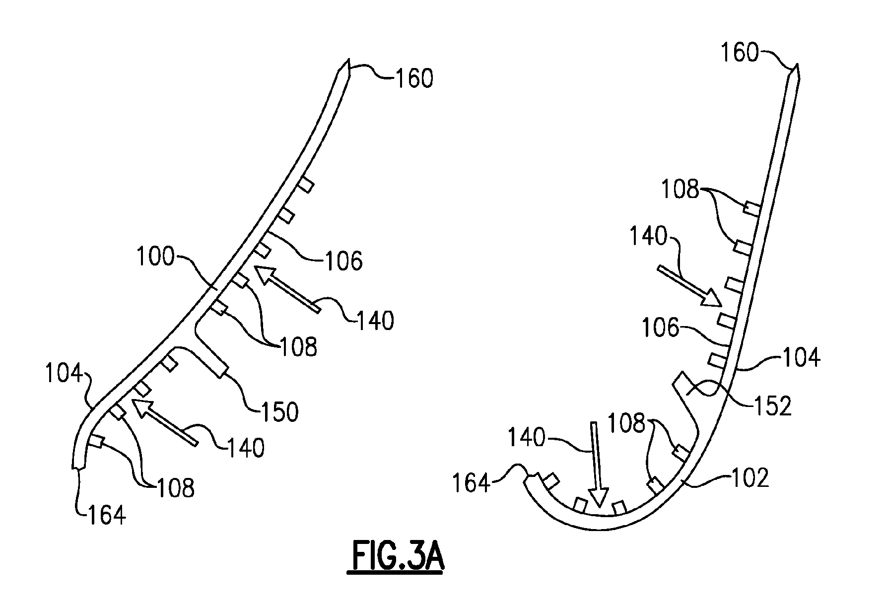
Figure 3A is a schematic cross-sectional view of an airfoil section of the blade ofFigure 2 formed as two pieces. -
Figure 3B is a view similar to 3A but showing the two pieces attached to each other. -
Figure 4 is a flow chart describing the method of forming the airfoil section. -
Figure 1 schematically illustrates agas turbine engine 20. Thegas turbine engine 20 is disclosed herein as a two-spool turbofan that generally incorporates afan section 22, a compressor section 24, a combustor section 26 and aturbine section 28. Alternative engines might include an augmentor section (not shown) among other systems or features. Thefan section 22 drives air along a bypass flow path B in a bypass duct defined within anacelle 15, while the compressor section 24 drives air along a core flow path C for compression and communication into the combustor section 26 then expansion through theturbine section 28. Although depicted as a two-spool turbofan gas turbine engine in the disclosed non-limiting embodiment, it should be understood that the concepts described herein are not limited to use with two-spool turbofans as the teachings may be applied to other types of turbine engines including three-spool architectures. - The
exemplary engine 20 generally includes alow speed spool 30 and ahigh speed spool 32 mounted for rotation about an engine central longitudinal axis A relative to an enginestatic structure 36 viaseveral bearing systems 38. It should be understood thatvarious bearing systems 38 at various locations may alternatively or additionally be provided, and the location ofbearing systems 38 may be varied as appropriate to the application. - The
low speed spool 30 generally includes aninner shaft 40 that interconnects afan 42, a first (or low) pressure compressor 44 and a second (or low)pressure turbine 46. Theinner shaft 40 is connected to thefan 42 through a speed change mechanism, which in exemplarygas turbine engine 20 is illustrated as a gearedarchitecture 48 to drive thefan 42 at a lower speed than thelow speed spool 30. Thehigh speed spool 32 includes anouter shaft 50 that interconnects a second (or high)pressure compressor 52 and a first (or high)pressure turbine 54. Acombustor 56 is arranged inexemplary gas turbine 20 between thehigh pressure compressor 52 and thehigh pressure turbine 54. Amid-turbine frame 57 of the enginestatic structure 36 is arranged generally between thehigh pressure turbine 54 and thelow pressure turbine 46. Themid-turbine frame 57 further supports bearingsystems 38 in theturbine section 28. Theinner shaft 40 and theouter shaft 50 are concentric and rotate viabearing systems 38 about the engine central longitudinal axis A which is collinear with their longitudinal axes. - The core airflow is compressed by the low pressure compressor 44 then the
high pressure compressor 52, mixed and burned with fuel in thecombustor 56, then expanded over thehigh pressure turbine 54 andlow pressure turbine 46. Themid-turbine frame 57 includesairfoils 59 which are in the core airflow path C. Theturbines low speed spool 30 andhigh speed spool 32 in response to the expansion. It will be appreciated that each of the positions of thefan section 22, compressor section 24, combustor section 26,turbine section 28, and fandrive gear system 48 may be varied. For example,gear system 48 may be located aft of combustor section 26 or even aft ofturbine section 28, andfan section 22 may be positioned forward or aft of the location ofgear system 48. - The
engine 20 in one example is a high-bypass geared aircraft engine. In a further example, theengine 20 bypass ratio is greater than about six (6), with an example embodiment being greater than about ten (10), the gearedarchitecture 48 is an epicyclic gear train, such as a planetary gear system or other gear system, with a gear reduction ratio of greater than about 2.3 and thelow pressure turbine 46 has a pressure ratio that is greater than about five. In one disclosed embodiment, theengine 20 bypass ratio is greater than about ten (10:1), the fan diameter is significantly larger than that of the low pressure compressor 44, and thelow pressure turbine 46 has a pressure ratio that is greater than about five 5:1.Low pressure turbine 46 pressure ratio is pressure measured prior to inlet oflow pressure turbine 46 as related to the pressure at the outlet of thelow pressure turbine 46 prior to an exhaust nozzle. The gearedarchitecture 48 may be an epicycle gear train, such as a planetary gear system or other gear system, with a gear reduction ratio of greater than about 2.3:1. It should be understood, however, that the above parameters are only exemplary of one embodiment of a geared architecture engine and that the present invention is applicable to other gas turbine engines including direct drive turbofans. - A significant amount of thrust is provided by the bypass flow B due to the high bypass ratio. The
fan section 22 of theengine 20 is designed for a particular flight condition -- typically cruise at about 0.8 Mach and about 35,000 feet (10,668 meters). The flight condition of 0.8 Mach and 35,000 ft (10,668 meters), with the engine at its best fuel consumption - also known as "bucket cruise Thrust Specific Fuel Consumption ('TSFC')" - is the industry standard parameter of lbm of fuel being burned divided by lbf of thrust the engine produces at that minimum point. "Low fan pressure ratio" is the pressure ratio across the fan blade alone, without a Fan Exit Guide Vane ("FEGV") system. The low fan pressure ratio as disclosed herein according to one non-limiting embodiment is less than about 1.45. "Low corrected fan tip speed" is the actual fan tip speed in ft/sec divided by an industry standard temperature correction of [(Tram °R) / (518.7 °R)]0.5. The "Low corrected fan tip speed" as disclosed herein according to one non-limiting embodiment is less than about 1150 ft / second (350.5 meters/second). - Airfoils located downstream of the combustor section 26, such as stator vanes and rotor blades in the
turbine section 28 for example, operate in a high-temperature environment. Airfoils that are exposed to high temperatures typically include cooling circuits with internal cooling channels that direct a flow of cooling air through the airfoil to remove heat and prolong the useful life of the airfoil.Figure 2 is a side view of aturbine rotor blade 60 having aroot section 62, aplatform 64, and anairfoil section 66.Root section 62 is connected to a rotor in the turbine section 28 (Figure 1 ) as known. Theairfoil section 66 includes aleading edge 68, a trailingedge 70, asuction side wall 72, and apressure side wall 74. Theairfoil section 66 extends to atip 76. In one example, theairfoil section 66 can optionally include a plurality of surface cooling holes, such as film cooling holes 78, and/or a plurality of trailingedge cooling slots 80. Although a blade is discussed in this disclosure, it should be understood that the invention also applies to other engine hardware, such as vanes, BOAS, combustor panels, etc. - The
platform 64 connects one end ofairfoil section 66 to rootsection 62. The leadingedge 68, trailingedge 70,suction side wall 72, andpressure side wall 74 extend outwardly away from theplatform 64. Thetip 76 closes off an opposite end of theairfoil section 66 from theplatform 64.Suction side wall 72 andpressure side wall 74connect leading edge 68 and trailingedge 70. In one example, film cooling holes 78 are arranged over a surface of theairfoil section 66 to provide a layer of cool air proximate the surface ofairfoil section 66 for protection from high-temperature combustion gases. Also, the trailingedge cooling slots 80 can be arranged along trailingedge 70 to provide an exit for air circulating withinairfoil section 66. - Due to the high operating temperatures to which the
blades 60 are subject to, the invention utilizes a high temperature alloy material, such as molybdenum for example, to form theair foil section 66 or theentire blade 60. In one example, the high temperature material is comprised of an alloy having greater than 90% molybdenum by weight. This material could also be used to form other gas turbine engine components such as vanes, combustor panels, and blade outer air seals (BOAS). It should be understood that molybdenum is only one example of a high temperature alloy material that could be used. Any other high temperature alloy materials suitable for forming gas turbine engine components could also be used such as monolithic ceramic material, or a ceramic matrix composite material, for example. The high temperature alloy material can withstand operating temperatures within a range of 2400-2700 degrees Fahrenheit (1316-1482 degrees Celsius), which is a much higher range than traditional airfoil materials can withstand. Traditional materials, such as a nickel alloy material for example, can only withstand temperatures up to 2200 degrees Fahrenheit (1204 degrees Celsius). - As shown in
Figure 3A , the blade is made by forming at least afirst portion 100 and asecond portion 102 from a high temperature alloy material. The first 100 and second 102 portions each define anexternal surface 104 and aninternal surface 106. At least oneheat transfer feature 108 is formed directly on theinternal surface 106 of the first 100 and second 102 portions. Once all of the heat transfer features 108 are formed on theinternal surfaces 106, the first 100 and second 102 portions are attached together to form the component. - As shown in
Figure 4 , first ablock 110 comprised of the high temperature alloy material is forged as one piece. Any type of forging process can be used to form theblock 110. Next, as indicated at 112, theblock 110 is cut into thefirst portion 100 and thesecond portion 102. Next, as indicated at 114, one or more heat transfer features 108 are machined directly onto theinternal surface 106 of both the first 100 and second 102 portions. As such, the heat transfer features 108 are integrally formed into theinternal wall surface 106, which significantly increase the cooling capability of theairfoil section 66. In one example, the heat transfer features 108 can comprise at least one of pin fins, trip strips, for example V-shaped trip strips, rounded protrusions, for example deptowarts, pedestals, dimples or cooling holes. The example ofFigures 3A-3B show pin fins. Examples of other heat transfer features, formed within an insert, are shown in co-pending applicationserial number 62/024,518 Figure 3A . - The
airfoil section 66 defines a center axis C (Figure 2 ) extending in a direction from anouter diameter surface 132 to aninner diameter surface 134. Because theairfoil section 66 is initially formed as first 100 and second 102 portions, the heat transfer features 108 can be machined in a direction that is generally transverse to the center axis C, as indicated at 140 inFigure 3A . The heat transfer features 108 can be machined using a plunging or wire electrical discharge machining (EDM) process, or by using a water-jetting process, for example. - The first 100 and second 102 portions each include
internal surface areas 142 that form part of one or more cooling passages 144 (Figure 3B ). For example, oneinternal surface area 142 on thefirst portion 100 forms one portion of acooling passage 144 while the opposinginternal surface area 142 on thesecond portion 102 forms the remaining portion of thecooling passage 144 when the first 100 and second 102 portions are attached to each other as shown inFigure 3B . - The
first portion 100 includes one or more firstinternal wall extensions 150 that extend outwardly from theinternal wall surface 106 toward the center of theairfoil section 66. Thesecond portion 102 includes one or more secondinternal wall extensions 152 that extend outwardly from theinternal wall surface 106 toward the center of theairfoil section 66. When the first 100 and second 102 portions are attached to each other, a distal end face of the firstinternal wall extension 150 abuts directly against a distal end face of the secondinternal wall extension 152. This interface divides the open area within theairfoil section 66 into at least two open cavities, i.e. thecooling passages 144. Additional wall extensions could also be formed on theinternal surface 106 to further sub-divide the internal open area as needed. - The contact between the first 150 and second 152 internal wall extensions forms one
attachment interface 154 between the first 100 and second 102 portions. At the trailingedge 70, each of the first 100 and second 102 portions include acontact surface 160 that abut directly against each other to form anotherattachment interface 162. At the leadingedge 68, each of the first 100 and second 102 portions include acontact surface 164 that abut directly against each other to form anotherattachment interface 166. - Once all of the internal machining has been completed, the first 100 and second 102 portions are attached to each other at the three
attachment interfaces Figure 4 . The corresponding portions of theportions leading edge 68, trailingedge 70 andinternal wall extensions portions portions portions blade 60 orairfoil section 66 could be formed from more than two portions. - Once the first 100 and second 102 portions are attached to each other, the
external surfaces 104 of the first 100 and second 102 portions are machined to provide a finished component as indicated at 172. This may include machining the film cooling holes and/or coolingslots 80, as needed, for example when anairfoil section 66 is being formed. Theairfoil section 66 can then be used as part of a gas turbine engine blade or vane, for example. - When using a single block of material, the engine components have to be machined to their final shape using line of sight processes such as plunge EDM, wire EDM, or water-jetting, for example. Thus, the internal cooling passages are only accessible for machining via the inner or outer diameter of the airfoil. As such, these processes move generally parallel to the walls to form smooth wall surfaces. By creating the component in two or more pieces and diffusion bonding the pieces together, the machining processes can move substantially perpendicular to the wall, allowing internal heat transfer features to be created on the internal cavity walls.
- Forming the heat transfer features directly into the wall provides the most effective heat transfer and significantly increases the cooling capability. Forming the heat transfer features directly on the internal wall of an engine component formed from a high temperature alloy can only be accomplished by creating the airfoil in multiple pieces and subsequently bonding the pieces together.
- Although an embodiment of this invention has been disclosed, a worker of ordinary skill in this art would recognize that certain modifications would come within the scope of this invention. For that reason, the following claims should be studied to determine the true scope and content of this invention.
Claims (15)
- A method for forming a gas turbine engine component (60) comprising the steps of:(a) forming a first portion (100) from a high temperature alloy material;(b) forming a second portion (102) from the high temperature alloy material, the first and second portions (100,102) each defining an external surface and an internal surface (142);(c) forming at least one heat transfer feature (108) directly on the internal surface (142) of at least one of the first and second portions (100,102); and(d) attaching the first and second portions (100,102) together to form a component (60).
- The method according to claim 1 wherein step (a) includes forging a block (110) comprised of the high temperature alloy material and cutting the block into the first portion (100) and the second portion (102).
- The method according to claim 2 including machining the external surfaces of the first and second portions (100,102) subsequent to step (d) to provide a finished component (60).
- The method according to any preceding claim wherein step (d) includes diffusion bonding the first and second portions (100,102) together.
- The method according to any of claims 1 to 3 wherein step (d) includes TLP bonding the first and second portions (100,102) together.
- The method according to any preceding claim wherein step (c) includes machining a plurality of heat transfer features (108) directly onto the internal surface (142) of both the first and second portions (100,102).
- The method according to claim 6 wherein step (c) includes machining the heat transfer features in a direction that is generally transverse to the internal surface.
- The method according to claim 6 or 7 wherein step (c) includes machining the heat transfer features using a plunging electrode or waterjet.
- A component (60) for a gas turbine engine comprising:a first portion (100) formed from a high temperature alloy material and having a first attachment interface (150);a second portion (102) formed from the high temperature alloy material and having a second attachment interface (152), the first and second portions (100,102) each defining an external surface and an internal surface (142);at least one heat transfer feature (108) formed directly on the internal surface (142) of at least one of the first and second portions (100,102); andthe first and second portions (100,102) being attached to each other via the first and second attachment interfaces (150,152) to form the component (60).
- The component according to claim 9 wherein, when the first and second attachment interfaces are attached to each other, the first and second attachment interfaces comprise a diffusion bonded interface or a TLP bonded interface.
- The component according to claim 9 or 10 wherein a plurality of heat transfer features (108) are formed directly onto the internal surface (142) of both the first and second portions (100,102).
- The method or component according to any preceding claim wherein the high temperature alloy material can withstand operating temperatures within a range of 2400-2700 degrees Fahrenheit (1316-1482°C).
- The method or component according to claim 12 wherein the high temperature alloy material includes molybdenum, wherein, optionally, the high temperature material is comprised of an alloy having greater than 90% molybdenum by weight.
- The method or component according to any preceding claim wherein the heat transfer features (108) comprise at least one of pin fins, trip strips, deptowarts, pedestals, or cooling holes.
- The method or component according to any preceding claim wherein the component (60) comprises one of a gas turbine engine blade, vane, BOAS, or combustor panel.
Applications Claiming Priority (1)
| Application Number | Priority Date | Filing Date | Title |
|---|---|---|---|
| US201462025519P | 2014-07-17 | 2014-07-17 |
Publications (1)
| Publication Number | Publication Date |
|---|---|
| EP2975215A1 true EP2975215A1 (en) | 2016-01-20 |
Family
ID=54010814
Family Applications (1)
| Application Number | Title | Priority Date | Filing Date |
|---|---|---|---|
| EP15176864.5A Withdrawn EP2975215A1 (en) | 2014-07-17 | 2015-07-15 | Method of creating heat transfer features in high temperature alloys |
Country Status (2)
| Country | Link |
|---|---|
| US (2) | US20170074116A1 (en) |
| EP (1) | EP2975215A1 (en) |
Cited By (4)
| Publication number | Priority date | Publication date | Assignee | Title |
|---|---|---|---|---|
| EP3339571A1 (en) * | 2016-11-17 | 2018-06-27 | United Technologies Corporation | Airfoil with panel having flow guide |
| WO2021191543A1 (en) * | 2020-03-27 | 2021-09-30 | Safran Ceramics | Turbine stator blade made of ceramic matrix composite material |
| EP4056809A1 (en) * | 2021-03-10 | 2022-09-14 | Raytheon Technologies Corporation | Airfoil fairing with rib having radial notch and gas turbine engine |
| EP4183984A1 (en) * | 2021-10-29 | 2023-05-24 | Pratt & Whitney Canada Corp. | Vane array structure for a hot section of a gas turbine engine |
Families Citing this family (3)
| Publication number | Priority date | Publication date | Assignee | Title |
|---|---|---|---|---|
| US20180306113A1 (en) * | 2017-04-19 | 2018-10-25 | United Technologies Corporation | Combustor liner panel end rail matching heat transfer features |
| DE102023108541A1 (en) * | 2023-04-04 | 2024-10-10 | MTU Aero Engines AG | Method for producing a guide vane, and associated guide vane |
| US12607126B2 (en) * | 2023-07-18 | 2026-04-21 | Rtx Corporation | Symmetrical two-piece hollow-vane assembly joined via brazing along airfoil centerline |
Citations (4)
| Publication number | Priority date | Publication date | Assignee | Title |
|---|---|---|---|---|
| US20020182070A1 (en) * | 2001-05-30 | 2002-12-05 | General Electric Company | Bonded niobium silicide and molybdenum silicide composite articles and method of manufacture |
| EP1629938A2 (en) * | 2004-08-26 | 2006-03-01 | United Technologies Corporation | Turbine engine component manufacture |
| US7311497B2 (en) * | 2005-08-31 | 2007-12-25 | United Technologies Corporation | Manufacturable and inspectable microcircuits |
| US20110143162A1 (en) * | 2009-12-14 | 2011-06-16 | Merrill Gary B | Process for Manufacturing a Component |
Family Cites Families (28)
| Publication number | Priority date | Publication date | Assignee | Title |
|---|---|---|---|---|
| US2477375A (en) * | 1944-03-22 | 1949-07-26 | Jablonsky Bruno | Method of manufacturing hollow articles of bonded fibrous laminae |
| US2848192A (en) * | 1953-03-12 | 1958-08-19 | Gen Motors Corp | Multi-piece hollow turbine bucket |
| US2958933A (en) * | 1955-07-22 | 1960-11-08 | Curtiss Wright Corp | Method for fabricating hollow blades |
| DE1776015A1 (en) * | 1968-09-04 | 1971-09-16 | Daimler Benz Ag | Turbine blade |
| US3888663A (en) * | 1972-10-27 | 1975-06-10 | Federal Mogul Corp | Metal powder sintering process |
| US3965963A (en) * | 1973-11-16 | 1976-06-29 | United Technologies Corporation | Mold and process for casting high temperature alloys |
| US4364160A (en) * | 1980-11-03 | 1982-12-21 | General Electric Company | Method of fabricating a hollow article |
| US5405242A (en) * | 1990-07-09 | 1995-04-11 | United Technologies Corporation | Cooled vane |
| US5176499A (en) * | 1991-06-24 | 1993-01-05 | General Electric Company | Photoetched cooling slots for diffusion bonded airfoils |
| US5360496A (en) * | 1991-08-26 | 1994-11-01 | Aluminum Company Of America | Nickel base alloy forged parts |
| US5693156A (en) * | 1993-12-21 | 1997-12-02 | United Technologies Corporation | Oxidation resistant molybdenum alloy |
| US5865909A (en) * | 1995-07-28 | 1999-02-02 | Iowa State University Research Foundation, Inc. | Boron modified molybdenum silicide and products |
| GB2306353B (en) * | 1995-10-28 | 1998-10-07 | Rolls Royce Plc | A method of manufacturing a blade |
| US5836075A (en) * | 1996-12-31 | 1998-11-17 | Westinghouse Electric Corporation | Process for forming combustion turbine components by transient liquid phase bonding |
| US5931638A (en) * | 1997-08-07 | 1999-08-03 | United Technologies Corporation | Turbomachinery airfoil with optimized heat transfer |
| US6325871B1 (en) * | 1997-10-27 | 2001-12-04 | Siemens Westinghouse Power Corporation | Method of bonding cast superalloys |
| CA2307471A1 (en) * | 1997-10-27 | 1999-05-06 | Siemens Westinghouse Power Corporation | Method of bonding cast superalloys |
| US6162347A (en) * | 1998-09-28 | 2000-12-19 | General Electric Company | Co-machined bonded airfoil |
| US6193465B1 (en) * | 1998-09-28 | 2001-02-27 | General Electric Company | Trapped insert turbine airfoil |
| US6193141B1 (en) * | 2000-04-25 | 2001-02-27 | Siemens Westinghouse Power Corporation | Single crystal turbine components made using a moving zone transient liquid phase bonded sandwich construction |
| DE10064267A1 (en) * | 2000-12-22 | 2002-07-04 | Alstom Switzerland Ltd | Process for quickly manufacturing hollow turbine blades for manufacturing development and component testing |
| GB0203955D0 (en) * | 2002-02-20 | 2002-04-03 | Rolls Royce Plc | A method of manufacturing an article by diffusion bonding and super[lastic forming |
| US6705011B1 (en) * | 2003-02-10 | 2004-03-16 | United Technologies Corporation | Turbine element manufacture |
| US7632455B2 (en) * | 2005-07-01 | 2009-12-15 | Ues, Inc. | High temperature niobium alloy |
| US20090060714A1 (en) * | 2007-08-30 | 2009-03-05 | General Electric Company | Multi-part cast turbine engine component having an internal cooling channel and method of forming a multi-part cast turbine engine component |
| US8661826B2 (en) * | 2008-07-17 | 2014-03-04 | Rolls-Royce Plc | Combustion apparatus |
| GB0903614D0 (en) * | 2009-03-04 | 2009-04-08 | Rolls Royce Plc | Method of manufacturing an aerofoil |
| US9249667B2 (en) * | 2012-03-15 | 2016-02-02 | General Electric Company | Turbomachine blade with improved stiffness to weight ratio |
-
2015
- 2015-07-09 US US14/794,861 patent/US20170074116A1/en not_active Abandoned
- 2015-07-15 EP EP15176864.5A patent/EP2975215A1/en not_active Withdrawn
-
2020
- 2020-11-23 US US17/101,712 patent/US20210254504A1/en not_active Abandoned
Patent Citations (4)
| Publication number | Priority date | Publication date | Assignee | Title |
|---|---|---|---|---|
| US20020182070A1 (en) * | 2001-05-30 | 2002-12-05 | General Electric Company | Bonded niobium silicide and molybdenum silicide composite articles and method of manufacture |
| EP1629938A2 (en) * | 2004-08-26 | 2006-03-01 | United Technologies Corporation | Turbine engine component manufacture |
| US7311497B2 (en) * | 2005-08-31 | 2007-12-25 | United Technologies Corporation | Manufacturable and inspectable microcircuits |
| US20110143162A1 (en) * | 2009-12-14 | 2011-06-16 | Merrill Gary B | Process for Manufacturing a Component |
Cited By (8)
| Publication number | Priority date | Publication date | Assignee | Title |
|---|---|---|---|---|
| EP3339571A1 (en) * | 2016-11-17 | 2018-06-27 | United Technologies Corporation | Airfoil with panel having flow guide |
| US10767487B2 (en) | 2016-11-17 | 2020-09-08 | Raytheon Technologies Corporation | Airfoil with panel having flow guide |
| WO2021191543A1 (en) * | 2020-03-27 | 2021-09-30 | Safran Ceramics | Turbine stator blade made of ceramic matrix composite material |
| FR3108667A1 (en) * | 2020-03-27 | 2021-10-01 | Safran Ceramics | Ceramic matrix composite turbine stator vane |
| CN115485453A (en) * | 2020-03-27 | 2022-12-16 | 赛峰航空陶瓷技术公司 | Turbine stator blade made of ceramic matrix composite |
| US11643936B1 (en) | 2020-03-27 | 2023-05-09 | Safran Ceramics | Turbine stator blade made of ceramic matrix composite material |
| EP4056809A1 (en) * | 2021-03-10 | 2022-09-14 | Raytheon Technologies Corporation | Airfoil fairing with rib having radial notch and gas turbine engine |
| EP4183984A1 (en) * | 2021-10-29 | 2023-05-24 | Pratt & Whitney Canada Corp. | Vane array structure for a hot section of a gas turbine engine |
Also Published As
| Publication number | Publication date |
|---|---|
| US20210254504A1 (en) | 2021-08-19 |
| US20170074116A1 (en) | 2017-03-16 |
Similar Documents
| Publication | Publication Date | Title |
|---|---|---|
| US9988913B2 (en) | Using inserts to balance heat transfer and stress in high temperature alloys | |
| US11148191B2 (en) | Core arrangement for turbine engine component | |
| US20210254504A1 (en) | Method of creating heat transfer features in high temperature alloys | |
| EP3009599A1 (en) | Gas turbine engine component with film cooling hole feature | |
| US10041358B2 (en) | Gas turbine engine blade squealer pockets | |
| US10612392B2 (en) | Gas turbine engine component with conformal fillet cooling path | |
| EP2993304B1 (en) | Gas turbine engine component with film cooling hole | |
| EP3118414A1 (en) | Gas turbine engine airfoil | |
| EP2993303B1 (en) | Gas turbine engine component with film cooling hole with pocket | |
| EP3112596A1 (en) | Gas turbine engine airfoil with bi-axial skin cooling passage and corresponding gas turbine engine | |
| EP3461993A1 (en) | Gas turbine engine airfoil | |
| EP3009600A1 (en) | Gas turbine engine turbine blade with cooled tip | |
| EP3054093B1 (en) | Arrangement of trip strips | |
| EP3051066B1 (en) | Casting core with staggered extensions | |
| US11149548B2 (en) | Method of reducing manufacturing variation related to blocked cooling holes | |
| EP3059391A1 (en) | Gas turbine engine turbine blade cooling using upstream stator vane | |
| EP3061913B1 (en) | Gas turbine engine airfoil cooling configuration with pressure gradient separators | |
| EP3049633A1 (en) | Diffused platform cooling holes | |
| EP2942486A1 (en) | Gas turbine engine airfoil cooling passage configuration |
Legal Events
| Date | Code | Title | Description |
|---|---|---|---|
| PUAI | Public reference made under article 153(3) epc to a published international application that has entered the european phase |
Free format text: ORIGINAL CODE: 0009012 |
|
| AK | Designated contracting states |
Kind code of ref document: A1 Designated state(s): AL AT BE BG CH CY CZ DE DK EE ES FI FR GB GR HR HU IE IS IT LI LT LU LV MC MK MT NL NO PL PT RO RS SE SI SK SM TR |
|
| AX | Request for extension of the european patent |
Extension state: BA ME |
|
| 17P | Request for examination filed |
Effective date: 20160720 |
|
| RBV | Designated contracting states (corrected) |
Designated state(s): AL AT BE BG CH CY CZ DE DK EE ES FI FR GB GR HR HU IE IS IT LI LT LU LV MC MK MT NL NO PL PT RO RS SE SI SK SM TR |
|
| RAP1 | Party data changed (applicant data changed or rights of an application transferred) |
Owner name: UNITED TECHNOLOGIES CORPORATION |
|
| STAA | Information on the status of an ep patent application or granted ep patent |
Free format text: STATUS: EXAMINATION IS IN PROGRESS |
|
| 17Q | First examination report despatched |
Effective date: 20200407 |
|
| RAP1 | Party data changed (applicant data changed or rights of an application transferred) |
Owner name: RAYTHEON TECHNOLOGIES CORPORATION |
|
| RAP3 | Party data changed (applicant data changed or rights of an application transferred) |
Owner name: RTX CORPORATION |
|
| STAA | Information on the status of an ep patent application or granted ep patent |
Free format text: STATUS: THE APPLICATION IS DEEMED TO BE WITHDRAWN |
|
| 18D | Application deemed to be withdrawn |
Effective date: 20241109 |