EP2975112B1 - Fermenter, plant and method for generating biogas - Google Patents
Fermenter, plant and method for generating biogas Download PDFInfo
- Publication number
- EP2975112B1 EP2975112B1 EP15001964.4A EP15001964A EP2975112B1 EP 2975112 B1 EP2975112 B1 EP 2975112B1 EP 15001964 A EP15001964 A EP 15001964A EP 2975112 B1 EP2975112 B1 EP 2975112B1
- Authority
- EP
- European Patent Office
- Prior art keywords
- steam
- fermenter
- feed device
- plant
- fermented
- Prior art date
- Legal status (The legal status is an assumption and is not a legal conclusion. Google has not performed a legal analysis and makes no representation as to the accuracy of the status listed.)
- Active
Links
- 238000000034 method Methods 0.000 title claims description 9
- 238000000855 fermentation Methods 0.000 claims description 45
- 230000004151 fermentation Effects 0.000 claims description 37
- 239000000463 material Substances 0.000 claims description 24
- 238000002485 combustion reaction Methods 0.000 claims description 8
- 239000011368 organic material Substances 0.000 claims description 5
- 239000011343 solid material Substances 0.000 claims description 3
- 239000002918 waste heat Substances 0.000 claims description 2
- 239000007789 gas Substances 0.000 description 20
- 241000196324 Embryophyta Species 0.000 description 18
- 238000004519 manufacturing process Methods 0.000 description 15
- 239000000758 substrate Substances 0.000 description 15
- 239000007787 solid Substances 0.000 description 14
- 239000007788 liquid Substances 0.000 description 11
- 238000003860 storage Methods 0.000 description 8
- 238000003756 stirring Methods 0.000 description 7
- 238000010438 heat treatment Methods 0.000 description 5
- VNWKTOKETHGBQD-UHFFFAOYSA-N methane Chemical compound C VNWKTOKETHGBQD-UHFFFAOYSA-N 0.000 description 4
- 239000000203 mixture Substances 0.000 description 4
- XLYOFNOQVPJJNP-UHFFFAOYSA-N water Substances O XLYOFNOQVPJJNP-UHFFFAOYSA-N 0.000 description 4
- 230000029087 digestion Effects 0.000 description 3
- 239000010871 livestock manure Substances 0.000 description 3
- 244000025254 Cannabis sativa Species 0.000 description 2
- 239000002361 compost Substances 0.000 description 2
- 210000003608 fece Anatomy 0.000 description 2
- 239000003337 fertilizer Substances 0.000 description 2
- -1 for example Substances 0.000 description 2
- 239000012528 membrane Substances 0.000 description 2
- 230000002906 microbiologic effect Effects 0.000 description 2
- 229920006395 saturated elastomer Polymers 0.000 description 2
- 238000000926 separation method Methods 0.000 description 2
- 239000004460 silage Substances 0.000 description 2
- 229910001220 stainless steel Inorganic materials 0.000 description 2
- 239000010935 stainless steel Substances 0.000 description 2
- 235000016068 Berberis vulgaris Nutrition 0.000 description 1
- 241000335053 Beta vulgaris Species 0.000 description 1
- 239000002028 Biomass Substances 0.000 description 1
- 229910000831 Steel Inorganic materials 0.000 description 1
- 240000008042 Zea mays Species 0.000 description 1
- 235000005824 Zea mays ssp. parviglumis Nutrition 0.000 description 1
- 235000002017 Zea mays subsp mays Nutrition 0.000 description 1
- 238000005299 abrasion Methods 0.000 description 1
- QVGXLLKOCUKJST-UHFFFAOYSA-N atomic oxygen Chemical compound [O] QVGXLLKOCUKJST-UHFFFAOYSA-N 0.000 description 1
- 230000015572 biosynthetic process Effects 0.000 description 1
- 230000015556 catabolic process Effects 0.000 description 1
- 238000010276 construction Methods 0.000 description 1
- 235000005822 corn Nutrition 0.000 description 1
- 238000005260 corrosion Methods 0.000 description 1
- 230000007797 corrosion Effects 0.000 description 1
- 125000004122 cyclic group Chemical group 0.000 description 1
- 238000006731 degradation reaction Methods 0.000 description 1
- 230000006866 deterioration Effects 0.000 description 1
- 238000006073 displacement reaction Methods 0.000 description 1
- 230000000694 effects Effects 0.000 description 1
- 230000005611 electricity Effects 0.000 description 1
- 238000005516 engineering process Methods 0.000 description 1
- 230000007717 exclusion Effects 0.000 description 1
- 230000004720 fertilization Effects 0.000 description 1
- 238000007667 floating Methods 0.000 description 1
- 239000012530 fluid Substances 0.000 description 1
- 239000011344 liquid material Substances 0.000 description 1
- 238000007726 management method Methods 0.000 description 1
- 238000002156 mixing Methods 0.000 description 1
- 239000003345 natural gas Substances 0.000 description 1
- 239000005416 organic matter Substances 0.000 description 1
- 239000001301 oxygen Substances 0.000 description 1
- 229910052760 oxygen Inorganic materials 0.000 description 1
- 238000009928 pasteurization Methods 0.000 description 1
- 230000008092 positive effect Effects 0.000 description 1
- 238000002360 preparation method Methods 0.000 description 1
- 238000005070 sampling Methods 0.000 description 1
- 239000002002 slurry Substances 0.000 description 1
- 239000010959 steel Substances 0.000 description 1
Images

Classifications
-
- C—CHEMISTRY; METALLURGY
- C12—BIOCHEMISTRY; BEER; SPIRITS; WINE; VINEGAR; MICROBIOLOGY; ENZYMOLOGY; MUTATION OR GENETIC ENGINEERING
- C12M—APPARATUS FOR ENZYMOLOGY OR MICROBIOLOGY; APPARATUS FOR CULTURING MICROORGANISMS FOR PRODUCING BIOMASS, FOR GROWING CELLS OR FOR OBTAINING FERMENTATION OR METABOLIC PRODUCTS, i.e. BIOREACTORS OR FERMENTERS
- C12M21/00—Bioreactors or fermenters specially adapted for specific uses
- C12M21/04—Bioreactors or fermenters specially adapted for specific uses for producing gas, e.g. biogas
-
- C—CHEMISTRY; METALLURGY
- C12—BIOCHEMISTRY; BEER; SPIRITS; WINE; VINEGAR; MICROBIOLOGY; ENZYMOLOGY; MUTATION OR GENETIC ENGINEERING
- C12M—APPARATUS FOR ENZYMOLOGY OR MICROBIOLOGY; APPARATUS FOR CULTURING MICROORGANISMS FOR PRODUCING BIOMASS, FOR GROWING CELLS OR FOR OBTAINING FERMENTATION OR METABOLIC PRODUCTS, i.e. BIOREACTORS OR FERMENTERS
- C12M27/00—Means for mixing, agitating or circulating fluids in the vessel
- C12M27/02—Stirrer or mobile mixing elements
- C12M27/06—Stirrer or mobile mixing elements with horizontal or inclined stirrer shaft or axis
-
- C—CHEMISTRY; METALLURGY
- C12—BIOCHEMISTRY; BEER; SPIRITS; WINE; VINEGAR; MICROBIOLOGY; ENZYMOLOGY; MUTATION OR GENETIC ENGINEERING
- C12M—APPARATUS FOR ENZYMOLOGY OR MICROBIOLOGY; APPARATUS FOR CULTURING MICROORGANISMS FOR PRODUCING BIOMASS, FOR GROWING CELLS OR FOR OBTAINING FERMENTATION OR METABOLIC PRODUCTS, i.e. BIOREACTORS OR FERMENTERS
- C12M29/00—Means for introduction, extraction or recirculation of materials, e.g. pumps
- C12M29/06—Nozzles; Sprayers; Spargers; Diffusers
-
- C—CHEMISTRY; METALLURGY
- C12—BIOCHEMISTRY; BEER; SPIRITS; WINE; VINEGAR; MICROBIOLOGY; ENZYMOLOGY; MUTATION OR GENETIC ENGINEERING
- C12M—APPARATUS FOR ENZYMOLOGY OR MICROBIOLOGY; APPARATUS FOR CULTURING MICROORGANISMS FOR PRODUCING BIOMASS, FOR GROWING CELLS OR FOR OBTAINING FERMENTATION OR METABOLIC PRODUCTS, i.e. BIOREACTORS OR FERMENTERS
- C12M33/00—Means for introduction, transport, positioning, extraction, harvesting, peeling or sampling of biological material in or from the apparatus
- C12M33/16—Screw conveyor
-
- Y—GENERAL TAGGING OF NEW TECHNOLOGICAL DEVELOPMENTS; GENERAL TAGGING OF CROSS-SECTIONAL TECHNOLOGIES SPANNING OVER SEVERAL SECTIONS OF THE IPC; TECHNICAL SUBJECTS COVERED BY FORMER USPC CROSS-REFERENCE ART COLLECTIONS [XRACs] AND DIGESTS
- Y02—TECHNOLOGIES OR APPLICATIONS FOR MITIGATION OR ADAPTATION AGAINST CLIMATE CHANGE
- Y02E—REDUCTION OF GREENHOUSE GAS [GHG] EMISSIONS, RELATED TO ENERGY GENERATION, TRANSMISSION OR DISTRIBUTION
- Y02E50/00—Technologies for the production of fuel of non-fossil origin
- Y02E50/30—Fuel from waste, e.g. synthetic alcohol or diesel
Definitions
- the invention relates to a fermenter for the production of biogas by anaerobic fermentation with at least one fermentation chamber and with at least one feed device, wherein the feed device is designed for introducing Fermentiergut into the fermentation chamber.
- the invention also relates to a plant for the production of biogas with at least one fermenter.
- the invention also relates to a process for the production of biogas by anaerobic fermentation of an organic fermentation product in a fermenter, wherein the fermentation material is introduced by means of a feed device into a fermentation chamber of the fermenter.
- the publication US4342836 A describes a system for the anaerobic treatment of organic material for the production of methane gas.
- the organic material is conveyed by means of a screw conveyor.
- the document describes an optional embodiment in which a fluid, such as steam or water, can be introduced under pressure.
- the object of the present invention is to provide a fermenter for the production of biogas, in which the disadvantages of the prior art are avoided.
- the feed device and the at least one steam injector can be arranged adjacent to one another. As a result, in particular heat losses can be reduced.
- the steam injector is preferably aligned with the fermentation material leaving the feeder.
- the steam injector may be formed as a steam lance. In this way, heat energy can be deliberately introduced.
- the feeder can be designed as a screw conveyor for at least largely solid Fermentiergut.
- the process efficiency can be increased if the fermenter is designed as a plug-flow fermenter.
- the object of the invention is also achieved by a plant for the production of biogas with at least one fermenter, which is formed according to the invention or according to an embodiment of the invention, wherein a steam supply device is provided, which is coupled via a steam supply to the steam injector.
- a gas-operated steam generator can be provided for providing steam.
- steam can be efficiently supplied to the steam injector at the temperature required by the process technology.
- the plant for the production of biogas can have a cogeneration plant with an internal combustion engine, wherein the cogeneration plant is coupled to the steam supply device such that the waste heat of the internal combustion engine is used to generate steam.
- the energy efficiency of the system can be increased.
- the object of the invention is also achieved by a method of the type mentioned, in which the Fermentiergut heat energy is supplied in the vicinity of the feeder by introducing steam. This causes a direct and relatively lossless heat transfer and it can be done a pre-digestion of Fermentierguts.
- the supply of heat energy takes place when the fermentation product enters the fermentation chamber.
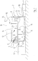
- FIG. 1 shows a part of a biogas plant 1 (see FIG. 2 ) with a fermenter 2 for the production of biogas by anaerobic fermentation of organic material.
- the fermenter 2 has a feed device 3 which is designed to introduce fermented material into a fermentation chamber 10 of the fermenter 2.
- the feed device 3 as indicated in the drawing is designed as a screw conveyor.
- This screw conveyor serves as an entry screw for solid Fermentiergut 41 (see FIG. 2 ).
- Solid Fermentiergut 41 or solid substrate can be supplied for example from the biowaste separation.
- Solid Fermentiergut 41 may be, for example, biomass of agricultural origin, such as corn, grass clippings, fodder beets, other plants and / or silage.
- the fermenter 2 has a feed line 4 for liquid Fermentiergut 42 (see FIG. 2 ) on.
- Liquid Fermentiergut 42 or liquid substrate is used in biogas plants as a basic substrate, for example, liquid manure are used as a liquid Fermentiergut 42 can.
- fermenter 2 In the fermenter 2 energetically usable biogas is obtained, which can be used as a fermenter 2 containers of different geometric structure, which may be arranged, for example, lying or standing.
- materials for the production of a fermenter tank for example, concrete and / or steel, in particular stainless steel, can be used.
- Standing fermenter containers can be designed, for example, with a round cross-section.
- Lying fermentor containers may for example have a rectangular or square cross-section.
- lying fermenter containers can also be substantially cylindrical.
- the in FIG. 1 shown fermenter 2 may be formed for example as a so-called plug flow fermenter, wherein the contents of the fermenter 2 due to the displacement effect of the introduced material - similar to a plug - in the horizontal direction through the fermentation chamber 10 of the fermenter 2 is transported. This results in a higher load capacity, low recirculation and positive effects on the degree of degradation and the Hygienisieriana of the material.
- a fermentation residue discharge device 17 is provided on the side of the housing 11 of the fermenter 2, which housing side of the feed device 3 and the feed line 4 is opposite.
- this Gärresteaustrags noticed 17 is coupled to a pump 18.
- a stirrer 12 is provided in the fermentation chamber 10.
- the agitator 12 has a stirring shaft 13, on which only partially provided with reference signs stirring tools 14 are arranged.
- the agitator 12 is designed as a reel agitator, wherein the stirring tools 14 are arranged as stirring arms along the agitator shaft 13.
- the stirring tools 14 project radially outward from the stirring shaft 13. It may be advantageous if the stirring tools 14 are arranged spirally at least in a partial region of the fermenter 2 and - as indicated in the drawing - are equipped at their ends with short paddles.
- the fermenter 2 can be designed as a main fermenter, which can be arranged downstream of a Nachfermenter, which can also be referred to as Nachgär theoryer.
- a secondary fermenter When a secondary fermenter is provided, it can be coupled to the main fermenter using the fermentation residue discharge device 17.
- the biogas produced in the fermenter 2 collects in a gas reservoir 16 below a cover 19.
- the gas reservoir 16 is bounded upwardly by the cover 19 and down through the mirror of the material located in the fermentation chamber 10 .
- the cover 19 may be formed, for example, as a film hood of flexible, gas-tight material.
- Another embodiment of the cover 19 is, for example, a so-called Tragluftdach or a separate concrete ceiling.
- an outer membrane is usually provided below which a gas storage membrane is arranged, through which limits the gas storage upwards becomes.
- a separate memory may be, for example, an external film gas storage.
- biogas can be taken for use in the gas reservoir 16.
- One of the types of use is, for example, to supply the biogas 55 obtained in the fermenter to a combined heat and power plant 24 (see FIG. 2 ).
- the biogas 55 can be converted into electricity, for example, to generate a monetary yield by feeding.
- the own power requirement of the biogas plant 1 can be covered from the power grid and / or at least partially by the combined heat and power plant 24.
- the fermenter 2 is equipped with a steam injector 7, which is arranged in the same region of the housing 11, in which the feed device 3 is arranged.
- the feeder 3 and the steam injector 7 are arranged adjacent to each other.
- the steam injector 7 is directed onto the solid fermenting material 41 introduced by the feeding device 3 into the fermenting chamber 10.
- the steam injector 7 may be formed, for example, as a steam lance and have a nozzle-shaped outlet opening 8 for steam. It is also possible to provide several vapor lances directed to the fermentation material.
- FIG. 1 shows an example of a trained as a steam lance steam injector 7, which is arranged below the feed device 3 for solid Fermentiergut 41.
- a steam supply device 5 provides steam 43 (see FIG. 2 ), ie water vapor, ready for the steam injector 7.
- the water vapor is the steam injector 7 by means of a Steam supply 6 supplied.
- the steam is provided as wet steam, possibly also as saturated steam or saturated steam.
- the steam that is, the water vapor, may have a temperature in a range of about 145 ° C to about 180 ° C, eg, about 165 ° C.
- the steam supply device 5 may be a steam generator that can be operated electrically and / or with gas.
- the steam supply device 5 may be formed, for example, as a fast steam generator.
- Fermentiergut 41 and 43 steam mix in the region of the steam inlet 9 and in its immediate vicinity, with the area of the steam inlet 9 is in spatial proximity of the feeder 3. Due to the fact that the fermentation material 41 and the steam 43 mix in the spatial vicinity of the feed device, a direct and comparatively loss-free heat transfer to the fermentation material is effected.
- the steam injector 7 is directed to the feeding device 3 leaving solid Fermentiergut 41.
- a pre-digestion of the fermentation product 41 can take place due to the locally limited high temperatures.
- the fermentation material 41 is supplied with heat energy as it enters or directly or at least almost immediately after entering the fermenter 2.
- steam injectors which are directed to the fermented material 41.
- the steam supply can be carried out continuously or clocked to the substrate entry.
- the substrate and the steam can be supplied both together and alternately and not together.
- FIG. 2 shows very schematically the structure of a plant 1 for the production of biogas.
- Appendix 1 is formed in a fermenter 2 Biogas 55 by anaerobic fermentation of Fermentiergut 41 and 42, which is present as an organic material.
- Anaerobic fermentation means that, with the exclusion of oxygen, organic matter is broken down by microbiological activity.
- the fermenter is fed solid fermented material 41 from a first source 20 for solid material and liquid fermented material 42 from a second source 22 for liquid material.
- Solid fermentation material 41 i. essentially solid substrate, may be, for example, silage, grass clippings, materials from biowaste separation and / or livestock manure.
- liquid fermentation product 42 i. liquid substrate, for example, liquid manure and / or liquids from the feedstock preparation, which may be subjected to pasteurization, may be used.
- the fermenter 2 is coupled to a steam supply device 5, wherein the fermenter 2 at least one steam injector 7 (see FIG. 1 ), to which steam 43 provided by the steam supply device 5 is supplied.
- the biogas 55 from the fermenter 2 is supplied to a combined heat and power plant 24 in the example shown.
- Fermentation residues 50 from the fermenter 2 can be used as fertilizer 51 and / or compost.
- fermentation residues 50 can be supplied from the fermenter 2 to a fermentation residue storage 23.
- the fermenter 2 is a Separatorvoriques 22 for the digestate 50 downstream.
- fertilizer 51 and / or compost can be separated from other digestate 52 which is fed to the fermentation residue store 23.
- the Gärrestelager 23 slurry can be removed 53, which can be used for example for fertilization in agriculture.
- usable biogas 54 can arise, which can be supplied to the combined heat and power plant 24 with appropriate design of the fermentation storage.
- electrical energy 46 and 45 heat won.
- Electrical energy 46 and heat 45 can be generated in the combined heat and power plant 24 using, for example, an internal combustion engine designed as a gas engine.
- the at least one internal combustion engine of the combined heat and power plant 24 may be coupled to one or more generators.
- the electrical energy 46 obtained in the combined heat and power plant 24 can be used outside the plant 1 and fed into a power grid for this purpose. Alternatively or additionally, the recovered electrical energy 46 can be returned to the system 1 and serve there for the power supply of electrical consumers, which are available for operating the system 1.
- the electrical energy 46 can be supplied to the steam supply device 5.
- the steam supply device 5 can be supplied with electrical energy 49 from another source.
- the heat 45 obtained in the combined heat and power plant 24 can be outside and / or used within the plant 1 for the production of biogas.
- the heat recovered 45 can be fed into a local heating network, for example, or be used to operate the plant 1 for the production of biogas 54, 55.
- at least a portion of the recovered heat 45 may be supplied to the steam delivery device 5.
- the steam supply device 5 can be supplied with heat 48 from another source.
- the steam supply device 5 can be supplied with gas 47, it being possible to use biogas, natural gas or liquid gas as the gas 47.
- gas 47 the steam supply device 5 also biogas 54, 55 are supplied, which is obtained within the plant 1 for the production of biogas. The latter embodiment is not shown in detail in the drawing for the sake of clarity.
- steam can also be supplied to the steam supply device 5.
- steam may e.g. be generated in the cogeneration unit 24.
- steam can be generated by the hot exhaust gases of an internal combustion engine of the combined heat and power plant 24.
- the supply of steam from the cogeneration unit 24 to the steam supply device 5 is not shown in detail in the drawing for the sake of clarity.
- steam can be generated with the aid of the internal combustion engine of the combined heat and power plant 24 and, in addition, a quick steam generator can be provided the quick steam generator is preferably operated gas.
- the invention relates to a fermenter 2 for producing biogas by anaerobic fermentation of organic substrate with at least one fermentation chamber 10 and at least one feed device 3, which is for introducing substrate, in particular solid substrate into the Fermentierhunt 10 is formed, wherein at least one steam injector 7 is provided for introducing steam 43 into the fermentation chamber 10, and wherein the feed device 3 and the steam injector 7 are arranged such that the registered substrate, in particular solid substrate, and the introduced steam 43rd in the vicinity of the feeder 3 mix.
- An advantage of the invention is that the substrate, in particular solid substrate, heat energy is supplied directly, whereby losses can be reduced.
- the invention also relates to a corresponding plant 1 for the production of biogas 54, 55 and to a process for the production of biogas 54, 55.
Description
Die Erfindung betrifft einen Fermenter zur Erzeugung von Biogas durch anaerobe Fermentation mit mindestens einer Fermentierkammer und mit mindestens einer Zuführeinrichtung, wobei die Zuführeinrichtung zum Eintragen von Fermentiergut in die Fermentierkammer ausgebildet ist.The invention relates to a fermenter for the production of biogas by anaerobic fermentation with at least one fermentation chamber and with at least one feed device, wherein the feed device is designed for introducing Fermentiergut into the fermentation chamber.
Die Erfindung betrifft auch eine Anlage zur Erzeugung von Biogas mit mindestens einem Fermenter.The invention also relates to a plant for the production of biogas with at least one fermenter.
Die Erfindung betrifft auch ein Verfahren zur Erzeugung von Biogas durch anaerobe Fermentation eines organischen Fermentierguts in einem Fermenter, wobei das Fermentiergut mittels einer Zuführeinrichtung in eine Fermentierkammer des Fermenters eingetragen wird.The invention also relates to a process for the production of biogas by anaerobic fermentation of an organic fermentation product in a fermenter, wherein the fermentation material is introduced by means of a feed device into a fermentation chamber of the fermenter.
Es ist Stand der Technik, zur Unterstützung des Fermentationsprozesses im Fermenter einer Biogasanlage Wärmeenergie in die Fermentationskammer einzubringen. In diesem Zusammenhang ist es bekannt, Boden-und/oder Wandheizungen einzusetzen. Bei Bodenheizungen, bei denen zum Beispiel Kunststoffheizspiralen in den Fermenterboden verlegt werden, können Sinkschichten zu einer starken Verschlechterung der Wärmeübertragung führen. Bei Wandheizungen ist es bekannt, Kunststoffheizrohre ähnlich wie bei der Bodenheizung in den Beton einzugießen. Eine bessere Wärmeübertragung liefern mit einigem Abstand an der Wand des Fermenters befestigte Edelstahl- oder Kunststoffrohre in zwei oder mehr Heizkreisen. Nachteilig ist bei den beschriebenen Heizungen unter anderem, dass häufig Probleme an den Wärmetauschern auftreten, beispielsweise durch Korrosion, Abrasion, Verkrustungen und/oder Verhängungen. Bei Plattenheizungen sind vergleichbare Probleme bekannt.It is state of the art to introduce thermal energy into the fermentation chamber to support the fermentation process in the fermenter of a biogas plant. In this context, it is known to use floor and / or wall heaters. For underfloor heating, where, for example, plastic heating coils are laid in the fermenter floor, sinking layers can lead to a severe deterioration of the heat transfer. In wall heaters, it is known to pour Kunststoffheizrohre similar to the floor heating in the concrete. Better heat transfer will be provided by stainless steel or plastic tubes mounted in two or more heating circuits at some distance on the wall of the fermenter. A disadvantage of the heaters described, inter alia, that often problems occur on the heat exchangers, for example, by corrosion, abrasion, encrustations and / or impositions. In panel heaters, similar problems are known.
Die Druckschrift
Diese Aufgabe wird bei einem Fermenter der eingangs genannten Art dadurch gelöst, dass
- a) mindestens ein Dampfinjektor zum Einbringen von Dampf vorgesehen ist;
- b) der Dampfinjektor unterhalb der Zuführeinrichtung angeordnet ist und die Zuführeinrichtung und der Dampfinjektor derart angeordnet sind, dass sich das Fermentiergut und der Dampf in räumlicher Nähe der Zuführeinrichtung vermengen.
- a) at least one steam injector is provided for introducing steam;
- b) the steam injector is arranged below the feed device and the feed device and the steam injector are arranged in such a way that the fermentation material and the steam mix in the spatial vicinity of the feed device.
Dadurch wird ein direkter und vergleichsweise verlustfreier Wärmeübergang bewirkt. Weiterhin kann ein Voraufschluss des Fermentierguts erfolgen.This causes a direct and relatively lossless heat transfer. Furthermore, a pre-digestion of the Fermentierguts take place.
Mit Vorteil können die Zuführeinrichtung und der mindestens eine Dampfinjektor benachbart zueinander angeordnet sein. Dadurch können insbesondere Wärmeverluste reduziert werden.Advantageously, the feed device and the at least one steam injector can be arranged adjacent to one another. As a result, in particular heat losses can be reduced.
Um einen möglichst direkten Wärmeübergang zu begünstigen, ist der Dampfinjektor vorzugsweise auf das die Zuführeinrichtung verlassende Fermentiergut ausgerichtet.In order to promote the most direct heat transfer, the steam injector is preferably aligned with the fermentation material leaving the feeder.
In weiterer Ausgestaltung der Erfindung kann der Dampfinjektor als Dampflanze ausgebildet sein. Derart kann Wärmeenergie gezielt eingebracht werden.In a further embodiment of the invention, the steam injector may be formed as a steam lance. In this way, heat energy can be deliberately introduced.
Um Fermentiergut möglichst bedarfsgerecht in den Fermenter einzutragen, kann die Zuführeinrichtung als Förderschnecke für zumindest weitestgehend festes Fermentiergut ausgebildet sein.To enter Fermentiergut as needed in the fermenter, the feeder can be designed as a screw conveyor for at least largely solid Fermentiergut.
Es kann hinsichtlich der Prozessführung von Vorteil sein, den Dampfinjektor unterhalb der Zuführeinrichtung anzuordnen.It may be advantageous in terms of process management to arrange the steam injector below the feeder.
Die Prozesseffizienz kann gesteigert werden, wenn der Fermenter als Pfropfenstromfermenter ausgebildet ist.The process efficiency can be increased if the fermenter is designed as a plug-flow fermenter.
Die Aufgabe der Erfindung wird auch gelöst durch eine Anlage zur Erzeugung von Biogas mit mindestens einem Fermenter, der gemäß der Erfindung oder gemäß einer Ausführung der Erfindung ausgebildet ist, wobei eine Dampfbereitstellungseinrichtung vorgesehen ist, welche über eine Dampfzuführung mit dem Dampfinjektor gekoppelt ist.The object of the invention is also achieved by a plant for the production of biogas with at least one fermenter, which is formed according to the invention or according to an embodiment of the invention, wherein a steam supply device is provided, which is coupled via a steam supply to the steam injector.
Bevorzugt kann zum Bereitstellen von Dampf ein Gas betriebener Dampferzeuger vorgesehen sein. Derart kann Dampf für den Dampfinjektor mit der prozesstechnisch erforderlichen Temperatur in effizienter Weise bereitgestellt werden.Preferably, a gas-operated steam generator can be provided for providing steam. Thus, steam can be efficiently supplied to the steam injector at the temperature required by the process technology.
In vorteilhafter Ausgestaltung kann die Anlage zur Erzeugung von Biogas ein Blockheizkraftwerk mit einem Verbrennungsmotor aufweisen, wobei das Blockheizkraftwerk derart mit der Dampfbereitstellungseinrichtung gekoppelt ist, dass die Abwärme des Verbrennungsmotors zur Dampferzeugung verwendet wird. Auf diese Weise kann die Energieeffizienz der Anlage gesteigert werden.In an advantageous embodiment, the plant for the production of biogas can have a cogeneration plant with an internal combustion engine, wherein the cogeneration plant is coupled to the steam supply device such that the waste heat of the internal combustion engine is used to generate steam. In this way, the energy efficiency of the system can be increased.
Die Aufgabe der Erfindung wird auch gelöst durch ein Verfahren der eingangs genannten Art, bei welchem dem Fermentiergut in räumlicher Nähe der Zuführeinrichtung durch Einbringen von Dampf Wärmeenergie zugeführt wird. Dadurch wird ein direkter und vergleichsweise verlustfreier Wärmeübergang bewirkt und es kann ein Voraufschluss des Fermentierguts erfolgen.The object of the invention is also achieved by a method of the type mentioned, in which the Fermentiergut heat energy is supplied in the vicinity of the feeder by introducing steam. This causes a direct and relatively lossless heat transfer and it can be done a pre-digestion of Fermentierguts.
Vorzugsweise erfolgt das Zuführen von Wärmeenergie beim Eintreten des Fermentierguts in die Fermentierkammer.Preferably, the supply of heat energy takes place when the fermentation product enters the fermentation chamber.
Weitere vorteilhafte Ausgestaltungen ergeben sich aus der nachfolgenden Beschreibung. Dabei werden Ausführungsbeispiele der Erfindung, ohne hierauf beschränkt zu sein, an Hand der Zeichnungen näher erläutert. Es zeigen, jeweils in vereinfachter, schematischer Darstellung:
- Figur 1
- einen Teil einer Biogasanlage
Figur 2- den Aufbau einer Biogasanlage
- FIG. 1
- a part of a biogas plant
- FIG. 2
- the construction of a biogas plant
Der Fermenter 2 weist eine Zuführeinrichtung 3 auf, die zum Eintragen von Fermentiergut in eine Fermentierkammer 10 des Fermenters 2 ausgebildet ist. Im gezeigten Beispiel ist die Zuführeinrichtung 3 wie in der Zeichnung angedeutet als Förderschnecke ausgebildet. Diese Förderschnecke dient als Eintragsschnecke für festes Fermentiergut 41 (siehe
Im gezeigten Beispiel weist der Fermenter 2 eine Zuführleitung 4 für flüssiges Fermentiergut 42 (siehe
Im Fermenter 2 wird energetisch verwertbares Biogas gewonnen, wobei als Fermenter 2 Behälter unterschiedlichen geometrischen Aufbaus zum Einsatz kommen können, welche beispielsweise liegend oder stehend angeordnet sein können. Als Materialen zur Fertigung eines Fermenterbehälters können beispielsweise Beton und/oder Stahl, insbesondere Edelstahl, verwendet werden. Stehende Fermenterbehälter können beispielsweise mit einem runden Querschnitt ausgeführt sein. Liegende Fermenterbehälter können beispielsweise einen rechteckigen oder quadratischen Querschnitt aufweisen. Liegende Fermenterbehälter können beispielsweise auch im Wesentlichen zylindrisch ausgebildet sein.In the
Der in
Im gezeigten Beispiel ist auf der Seite des Gehäuses 11 des Fermenters 2, welche Gehäuseseite der Zuführeinrichtung 3 und der Zuführleitung 4 gegenüberliegt, eine Gärresteaustragseinrichtung 17 vorgesehen. Im Beispiel ist diese Gärresteaustragseinrichtung 17 mit einer Pumpe 18 gekoppelt.In the example shown, a fermentation
In der Fermentierkammer 10 ist ein Rührwerk 12 vorgesehen. Das Rührwerk 12 weist eine Rührwelle 13 auf, an der nur teilweise mit Bezugszeichen versehene Rührwerkzeuge 14 angeordnet sind. Mittels des Rührwerks 12 erfolgt eine Durchmischung des Fermenterinhalts, wobei die Bildung von Schwimm- und Sinkschichten verringert wird und die mikrobiologische Aktivität im Fermenter positiv beeinflusst wird. Im gezeigten Beispiel ist das Rührwerk 12 als Haspelrührwerk ausgebildet, wobei die Rührwerkzeuge 14 als Rührarme entlang der Rührwelle 13 angeordnet sind. Im gezeigten Beispiel ragen die Rührwerkzeuge 14 von der Rührwelle 13 radial nach außen. Es kann vorteilhaft sein, wenn die Rührwerkzeuge 14 zumindest in einem Teilbereich des Fermenters 2 spiralförmig angeordnet sind und - wie in der Zeichnung angedeutet - an ihren Enden mit kurzen Paddeln ausgestattet sind.In the
Der Fermenter 2 kann als Hauptfermenter ausgebildet sein, dem ein Nachfermenter, der auch als Nachgärbehälter bezeichnet werden kann, nachgeordnet sein kann. Bei Vorsehen eines Nachfermenters kann dieser unter Verwendung der Gärresteaustragseinrichtung 17 mit dem Hauptfermenter gekoppelt sein. In den Zeichnungen nicht näher dargestellt ist die Möglichkeit, einen kontinuierlich betriebenen Fermenter 2 mit einer Hauptfermentierkammer und mit einer Nachfermentierkammer auszustatten. Diese Möglichkeit wird z.B. in der
Das Biogas, welches im Fermenter 2 entsteht, sammelt sich in einem Gasspeicher 16 unterhalb einer Abdeckung 19. Wie im Beispiel schematisch gezeigt, wird der Gasspeicher 16 nach oben durch die Abdeckung 19 und nach unten durch den Spiegel des in der Fermentierkammer 10 befindlichen Materials begrenzt. Die Abdeckung 19 kann beispielsweise als Folienhaube aus flexiblem, gasdichten Material ausgebildet sind. Eine andere Ausführungsform der Abdeckung 19 ist beispielsweise ein sogenanntes Tragluftdach oder eine separate Betondecke. Bei einem Tragluftdach ist in der Regel eine Außenmembrane vorgesehen unterhalb derer eine Gasspeichermembrane angeordnet ist, durch welche der Gasspeicher nach oben begrenzt wird. Alternativ oder zusätzlich zur gezeigten Anordnung des Gasspeichers 16 ist es auch möglich einen gesonderten Speicher zur Gaslagerung vorzusehen. Ein gesonderter Speicher kann z.B. ein externer Foliengasspeicher sein.The biogas produced in the
Mittels einer in der Zeichnung lediglich angedeuteten Gasentnahmeeinrichtung 15 kann dem Gasspeicher 16 Biogas zur Nutzung entnommen werden. Eine der Nutzungsarten ist es beispielsweise, das im Fermenter gewonnene Biogas 55 einem Blockheizkraftwerk 24 zuzuführen (siehe
Im gezeigten Beispiel ist der Fermenter 2 mit einem Dampfinjektor 7 ausgestattet, der im selben Bereich des Gehäuses 11 angeordnet ist, in dem auch die Zuführeinrichtung 3 angeordnet ist. Die Zuführeinrichtung 3 und der Dampfinjektor 7 sind benachbart zueinander angeordnet. Der Dampfinjektor 7 ist auf das von der Zuführeinrichtung 3 in die Fermentierkammer 10 eingetragene feste Fermentiergut 41 gerichtet. Wie in der Zeichnung angedeutet, kann der Dampfinjektor 7 beispielsweise als Dampflanze ausgebildet sein und eine düsenförmige Austrittsöffnung 8 für Dampf aufweisen. Es können auch mehrere auf das Fermentiergut gerichtete Dampflanzen vorgesehen sein.
Eine Dampfbereitstellungseinrichtung 5 stellt Dampf 43 (siehe
Mit Hilfe des Dampfinjektors 7 wird Wärmeenergie in direkter räumlicher Nähe zum Substrateintrag in den Fermenter eingebracht. Fermentiergut 41 und Dampf 43 vermengen sich im Bereich des Dampfeintritts 9 bzw. in dessen unmittelbarer Umgebung, wobei sich der Bereich des Dampfeintritts 9 in räumlicher Nähe der Zuführeinrichtung 3 befindet. Dadurch, dass sich das Fermentiergut 41 und der Dampf 43 in räumlicher Nähe der Zuführeinrichtung vermengen wird ein direkter und vergleichsweise verlustfreier Wärmeübergang auf das Fermentiergut bewirkt.With the help of the steam injector 7 heat energy is introduced in direct spatial proximity to the substrate entry into the fermenter. Fermentiergut 41 and 43 steam mix in the region of the
Der Dampfinjektor 7 ist auf das die Zuführeinrichtung 3 verlassende feste Fermentiergut 41 gerichtet. Dabei kann durch die lokal begrenzt hohen Temperaturen ein Voraufschluss des Fermentierguts 41 erfolgen. Im gezeigten Beispiel wird dem Fermentiergut 41 beim Eintreten bzw. unmittelbar oder zumindest nahezu unmittelbar nach dem Eintreten in den Fermenter 2 Wärmeenergie zugeführt. Es können weitere, nicht näher dargestellte Dampfinjektoren vorgesehen sein, die auf das Fermentiergut 41 gerichtet sind.The steam injector 7 is directed to the feeding device 3 leaving
Die Dampfzuführung kann kontinuierlich oder getaktet zum Substrateintrag erfolgen. Bei einer taktweisen Dampfzuführung können das Substrat und der Dampf sowohl gemeinsam als auch alternierend und nicht gemeinsam zugeführt werden.The steam supply can be carried out continuously or clocked to the substrate entry. In a cyclic steam supply, the substrate and the steam can be supplied both together and alternately and not together.
Im gezeigten Beispiel wird dem Fermenter festes Fermentiergut 41 aus einer ersten Quelle 20 für festes Material und flüssiges Fermentiergut 42 aus einer zweiten Quelle 22 für flüssiges Material zugeführt. Festes Fermentiergut 41, d.h. im Wesentlichen Festsubstrat, kann beispielsweise Silage, Grasschnitt, Materialien aus der Bioabfall-Trennung und/oder Festmist aus der Tierhaltung sein. Als flüssiges Fermentiergut 42, d.h. im Wesentlichen Flüssigsubstrat, können beispielsweise Flüssigmist und/oder Flüssigkeiten aus der Speiseresteaufbereitung, die ggf. einer Pasteurisierung unterzogen werden, verwendet werden.In the example shown, the fermenter is fed solid fermented
Der Fermenter 2 ist mit einer Dampfbereitstellungseinrichtung 5 gekoppelt, wobei der Fermenter 2 mindestens einen Dampfinjektor 7 (siehe
Das Biogas 55 aus dem Fermenter 2 wird im gezeigten Beispiel einem Blockheizkraftwerk 24 zugeführt.The
Gärreste 50 aus dem Fermenter 2 können als Düngemittel 51 und/oder Kompost verwendet werden. In alternativer oder zusätzlicher Verwendung können Gärreste 50 aus dem Fermenter 2 einem Gärrestelager 23 zugeführt werden. Im gezeigten Beispiel ist dem Fermenter 2 eine Separatorvorrichtung 22 für die Gärreste 50 nachgeordnet. Mittels der Separatorvorrichtung 22 können Düngemittel 51 und/oder Kompost von übrigen Gärresten 52, die dem Gärrestelager 23 zugeführt werden, getrennt werden. Dem Gärrestelager 23 kann Gülle 53 entnommen werden, welche beispielsweise zum Düngen in der Landwirtschaft eingesetzt werden kann. Auch im Gärrestelager 23 kann nutzbares Biogas 54 entstehen, welches bei entsprechender Ausgestaltung des Gärrestelagers dem Blockheizkraftwerk 24 zugeführt werden kann.
Im Blockheizkraftwerk 24, das vorzugsweise modular aufgebaut ist, werden aus dem Biogas 55, 54 elektrische Energie 46 und Wärme 45 gewonnen. Elektrische Energie 46 und Wärme 45 können im Blockheizkraftwerk 24 beispielsweise unter Verwendung eines als Gasmotor ausgebildeten Verbrennungsmotors erzeugt werden. Zur Gewinnung von elektrischer Energie 46 kann der mindestens eine Verbrennungsmotor des Blockheizkraftwerks 24 mit einem oder mehreren Generatoren gekoppelt sein.In the combined heat and
Die in dem Blockheizkraftwerk 24 gewonnene elektrische Energie 46 kann außerhalb der Anlage 1 genutzt und hierzu in ein Energienetz eingespeist werden. Alternativ oder ergänzend kann die gewonnene elektrische Energie 46 wieder in die Anlage 1 zurückgeführt werden und dort zur Energieversorgung von elektrischen Verbrauchern dienen, welche zum Betrieb der Anlage 1 vorhanden sind.The
Beispielsweise kann zumindest ein Teil der elektrischen Energie 46 der Dampfbereitstellungseinrichtung 5 zugeführt werden. Alternativ oder zusätzlich zu der vom Blockheizkraftwerk 24 bereitgestellten elektrischen Energie 46, kann der Dampfbereitstellungseinrichtung 5 elektrische Energie 49 aus anderer Quelle zugeführt werden.For example, at least part of the
Die im Blockheizkraftwerk 24 gewonnene Wärme 45 kann außerhalb und/oder innerhalb der Anlage 1 zur Erzeugung von Biogas genutzt werden. So kann die gewonnene Wärme 45 z.B. in ein Nahwärmenetz eingespeist werden bzw. zum Betrieb der Anlage 1 zur Erzeugung von Biogas 54, 55 genutzt werden. Beispielsweise kann zumindest ein Teil der gewonnenen Wärme 45 der Dampfbereitstellungseinrichtung 5 zugeführt werden. Alternativ oder zusätzlich zu der vom Blockheizkraftwerk 24 bereitgestellten Wärme 45, kann der Dampfbereitstellungseinrichtung 5 Wärme 48 aus anderer Quelle zugeführt werden.The
Zum Erzeugen von Dampf 43 kann der Dampfbereitstellungseinrichtung 5 Gas 47 zugeführt werden, wobei als Gas 47 Biogas, Erdgas oder auch Flüssiggas verwendet werden kann. Beispielsweise kann ein Schnelldampferzeuger mit Gas 47 betrieben werden. Als Gas 47 kann der Dampfbereitstellungseinrichtung 5 auch Biogas 54, 55 zugeführt werden, welches innerhalb der Anlage 1 zur Erzeugung von Biogas gewonnen wird. Letztere Ausführung ist in der Zeichnung der besseren Übersicht halber nicht näher dargestellt.For generating
Alternativ oder zusätzlich zu der elektrischen Energie 46, 49, der Wärme 45, 48 und/oder dem Gas 47, kann der Dampfbereitstellungseinrichtung 5 auch Dampf zugeführt werden. Außerhalb der Dampfbereitstellungseinrichtung 5 kann Dampf z.B. im Blockheizkraftwerk 24 erzeugt werden. So kann beispielsweise durch die heißen Abgase eines Verbrennungsmotors des Blockheizkraftwerks 24 Dampf erzeugt werden. Die Zuführung von Dampf vom Blockheizkraftwerk 24 zur Dampfbereitstellungseinrichtung 5 ist in der Zeichnung der besseren Übersicht halber nicht näher dargestellt.Alternatively or in addition to the
Um Dampf 43 für den Dampfinjektor 7 bedarfsgerecht und effizient bereitzustellen, kann unter Zuhilfenahme des Verbrennungsmotors des Blockheizkraftwerks 24 Dampf erzeugt werden und zusätzlich ein Schnelldampferzeuger vorgesehen sein, wobei der Schnelldampferzeuger vorzugsweise Gas betrieben ist.In order to provide
Ein für die Erfindung wesentlicher Gedanke lässt sich wie folgt zusammenfassen: Die Erfindung betrifft einen Fermenter 2 zur Erzeugung von Biogas durch anaerobe Fermentation organischen Substrats mit mindestens einer Fermentierkammer 10 und mit mindestens einer Zuführeinrichtung 3, welche zum Eintragen von Substrat, insbesondere Festsubstrat, in die Fermentierkammer 10 ausgebildet ist, wobei mindestens ein Dampfinjektor 7 zum Einbringen von Dampf 43 in die Fermentierkammer 10 vorgesehen ist, und wobei die Zuführeinrichtung 3 und der Dampfinjektor 7 derart zueinander angeordnet sind, dass sich das eingetragene Substrat, insbesondere Festsubstrat, und der eingebrachte Dampf 43 in räumlicher Nähe der Zuführeinrichtung 3 vermengen. Ein Vorteil der Erfindung liegt darin, dass dem Substrat, insbesondere Festsubstrat, Wärmeenergie direkt zugeführt wird, wobei Verluste reduziert werden können. Die Erfindung betrifft auch eine entsprechende Anlage 1 zur Erzeugung von Biogas 54, 55 sowie ein Verfahren zur Erzeugung von Biogas 54, 55.An inventive idea can be summarized as follows: The invention relates to a
Claims (10)
- Fermenter (2) for generating biogas by anaerobic fermentation, having at least one fermentation chamber (10) and having at least one feed device (3), wherein the feed device (3) is designed for introducing material to be fermented (41) into the fermentation chamber (10),
characterized in thata) at least one steam injector (7) is provided for introducing steam (43);b) the steam injector (7) is arranged below the feed device (3), and the steam injector (7) is directed at the solid material to be fermented (41) which is exiting the feed device (3) and being introduced into the fermentation chamber (10), with the result that the material to be fermented (41) and the steam (43) mix in the spatial proximity of the feed device (3). - Fermenter (2) according to Claim 1, characterized in that the feed device (3) and the at least one steam injector (7) are arranged adjacent to one another.
- Fermenter (2) according to either of Claims 1 and 2, characterized in that the steam injector (7) is designed as a steam lance.
- Fermenter (2) according to one of Claims 1 to 3, characterized in that the feed device (3) is designed as a conveying screw for at least substantially solid material to be fermented (41).
- Fermenter (2) according to one of Claims 1 to 4, characterized in that the fermenter (2) is designed as a plug flow fermenter.
- Plant for generating biogas, having at least one fermenter (2) according to one of the preceding claims, and having a steam provision device (5) which is coupled to the steam injector (7) via a steam feed (6).
- Plant for generating biogas according to Claim 6, characterized in that, for providing steam, a gas-operated steam generator is provided.
- Plant for generating biogas according to Claim 6 or 7, characterized in that the plant (1) has a cogeneration unit (24) with a combustion engine, wherein the cogeneration unit (24) is coupled to the steam provision device (5) such that the waste heat of the combustion engine is used for generating steam.
- Method for generating biogas (55) by anaerobic fermentation of an organic material to be fermented (41) in a fermenter (2) according to one of Claims 1-5, wherein the material to be fermented (41) is introduced into a fermentation chamber (10) of the fermenter (2) by means of a feed device (3),
characterized in that
heat energy is supplied to the material to be fermented (41) in the spatial proximity of the feed device (3) by the introduction of steam (43). - Method according to Claim 9, characterized in that the supply of heat energy occurs when the material to be fermented (41) enters the fermentation chamber (10) .
Applications Claiming Priority (1)
| Application Number | Priority Date | Filing Date | Title |
|---|---|---|---|
| DE102014010641.1A DE102014010641A1 (en) | 2014-07-17 | 2014-07-17 | Fermenter, plant and process for the production of biogas |
Publications (2)
| Publication Number | Publication Date |
|---|---|
| EP2975112A1 EP2975112A1 (en) | 2016-01-20 |
| EP2975112B1 true EP2975112B1 (en) | 2018-09-05 |
Family
ID=53513917
Family Applications (1)
| Application Number | Title | Priority Date | Filing Date |
|---|---|---|---|
| EP15001964.4A Active EP2975112B1 (en) | 2014-07-17 | 2015-07-01 | Fermenter, plant and method for generating biogas |
Country Status (2)
| Country | Link |
|---|---|
| EP (1) | EP2975112B1 (en) |
| DE (1) | DE102014010641A1 (en) |
Families Citing this family (4)
| Publication number | Priority date | Publication date | Assignee | Title |
|---|---|---|---|---|
| DE102016003256A1 (en) | 2016-03-16 | 2017-09-21 | Eisenmann Se | Plant and process for the utilization of biomaterial |
| AT518499A1 (en) * | 2016-04-04 | 2017-10-15 | Sfl Tech Gmbh | Method and device for the treatment of biomass |
| DE102017113027A1 (en) | 2017-06-13 | 2018-12-13 | N-ERGIE Aktiengesellschaft | Method for storing and storing hydrogen |
| DE102017113028B3 (en) * | 2017-06-13 | 2018-11-08 | N-ERGIE Aktiengesellschaft | Process for the conversion of a biogas plant |
Family Cites Families (6)
| Publication number | Priority date | Publication date | Assignee | Title |
|---|---|---|---|---|
| US4342836A (en) * | 1980-10-17 | 1982-08-03 | Harvey Christian D | Continuous anaerobic digestor system |
| FR2519965A1 (en) * | 1982-01-20 | 1983-07-22 | Defontaine Sa | Digestion of sewage sludge to produce methane and fertiliser - passes incoming sludge through steam ejector:mixer to preheat to about 95 deg. C |
| DE202006013772U1 (en) | 2006-09-06 | 2006-11-16 | Eisenmann Maschinenbau Gmbh & Co. Kg | Biogas production plant comprises housing, fermentation tank to receive fermentation material, biogas storage connected with the fermentation tank, and feeding device to supply solid fermentation material into the fermentation |
| KR100914667B1 (en) * | 2009-01-14 | 2009-08-28 | (주) 친환경과대체에너지 | Food waste treating equipment comprising of anaerobic digestion hydrolysis unit |
| AT509319B1 (en) * | 2010-05-25 | 2011-08-15 | Biogas Systems Gmbh | METHOD AND DEVICE FOR HYDROLYSIS OF PREFERABLY SOLID, ORGANIC SUBSTRATES |
| DE102012025027A1 (en) * | 2012-12-20 | 2014-06-26 | Reiflock Abwassertechnik Gmbh | Apparatus and method for the treatment of biomass |
-
2014
- 2014-07-17 DE DE102014010641.1A patent/DE102014010641A1/en not_active Ceased
-
2015
- 2015-07-01 EP EP15001964.4A patent/EP2975112B1/en active Active
Also Published As
| Publication number | Publication date |
|---|---|
| DE102014010641A1 (en) | 2016-01-21 |
| EP2975112A1 (en) | 2016-01-20 |
Similar Documents
| Publication | Publication Date | Title |
|---|---|---|
| EP2975112B1 (en) | Fermenter, plant and method for generating biogas | |
| EP1929024B1 (en) | Process for the production of biogas employing a substrate having a high solids and high nitrogen content | |
| AT507469B1 (en) | DEVICE FOR CONTINUOUS OR DISCONTINUOUS HYDROLYSIS OF ORGANIC SUBSTRATES | |
| DE19958142A1 (en) | Transportable, modular biogas production plant, consists of separate fermenter and energy supply units which are mounted in standard freight containers or container frames | |
| DE102008015240A1 (en) | Combined plant for the production of biogas and compost and method for switching a fermenter in such a plant between biogas production and composting | |
| EP1972691A1 (en) | Process for the production of biogas by discontinuous, 2-step solids fermentation | |
| EP2878365A2 (en) | Agitator for a biogas fermenter | |
| Borek et al. | The analysis of a prototype installation for biogas production from chosen agricultural substrates | |
| WO2014094734A2 (en) | Energy conversion system | |
| DE102009040195A1 (en) | Method and device for treating fermentable substances | |
| EP0172443B1 (en) | Process and device for anaerobically treating organic substrates in order to produce biogas | |
| EP2597144A1 (en) | Apparatus for the fermentation of organic solids | |
| DE19946299C2 (en) | Process and device for the joint fermentation of carbohydrate, fat and protein-containing bio-waste, cellulose-rich bio-waste, digested sludge from sewage treatment plants as well as paper sludge and whey | |
| DE102009007902A1 (en) | Biogas plant for producing gas from a substrate, comprises a decomposition reaction section for the decomposition of the substrate, and a methane-forming reaction section for the formation of methane from the substrate | |
| DE3427976A1 (en) | Process and apparatus for the anaerobic treatment of substrates containing organic substances for generating biogas | |
| EP3219783A1 (en) | Installation and method for the use of biomaterial | |
| DE102007024947A1 (en) | Biogas fermenter for producing biogas or bio-ethanol from water and lignocellulose containing biomass, includes agitator for agitating digester content, which is located at outside of digestion tank | |
| DE102014011479A1 (en) | New process for the fermentation of biogenic energy sources | |
| DE102011054298A1 (en) | Methane production unit comprises fermenter with enclosed inner volume having surface for immobilized microorganisms, where inner volume is connected with environment by e.g. substrate gas inlet, synthesis gas outlet and supply line | |
| DE102013102642A1 (en) | Method and device for producing biogas | |
| EP3034603A1 (en) | Enhanced biogas plant | |
| DE102020109419A1 (en) | Biological methane production | |
| DE102009007903A1 (en) | Piping system for a biogas plant for generating gas from a substrate, comprises a decomposition tube for decomposition reaction section for the decomposition of the substrate, and a methane-forming tube for methane-forming reaction section | |
| Prasad et al. | Anaerobic Digesters for Manure Management at Livestock Operations | |
| Giraldi et al. | Biocells for biogas production: anaerobic plant for the energetic enhancement of biomasses and zootechnical slurry |
Legal Events
| Date | Code | Title | Description |
|---|---|---|---|
| PUAI | Public reference made under article 153(3) epc to a published international application that has entered the european phase |
Free format text: ORIGINAL CODE: 0009012 |
|
| AK | Designated contracting states |
Kind code of ref document: A1 Designated state(s): AL AT BE BG CH CY CZ DE DK EE ES FI FR GB GR HR HU IE IS IT LI LT LU LV MC MK MT NL NO PL PT RO RS SE SI SK SM TR |
|
| AX | Request for extension of the european patent |
Extension state: BA ME |
|
| 17P | Request for examination filed |
Effective date: 20160719 |
|
| RBV | Designated contracting states (corrected) |
Designated state(s): AL AT BE BG CH CY CZ DE DK EE ES FI FR GB GR HR HU IE IS IT LI LT LU LV MC MK MT NL NO PL PT RO RS SE SI SK SM TR |
|
| GRAP | Despatch of communication of intention to grant a patent |
Free format text: ORIGINAL CODE: EPIDOSNIGR1 |
|
| STAA | Information on the status of an ep patent application or granted ep patent |
Free format text: STATUS: GRANT OF PATENT IS INTENDED |
|
| INTG | Intention to grant announced |
Effective date: 20180227 |
|
| GRAS | Grant fee paid |
Free format text: ORIGINAL CODE: EPIDOSNIGR3 |
|
| GRAA | (expected) grant |
Free format text: ORIGINAL CODE: 0009210 |
|
| STAA | Information on the status of an ep patent application or granted ep patent |
Free format text: STATUS: THE PATENT HAS BEEN GRANTED |
|
| AK | Designated contracting states |
Kind code of ref document: B1 Designated state(s): AL AT BE BG CH CY CZ DE DK EE ES FI FR GB GR HR HU IE IS IT LI LT LU LV MC MK MT NL NO PL PT RO RS SE SI SK SM TR |
|
| REG | Reference to a national code |
Ref country code: GB Ref legal event code: FG4D Free format text: NOT ENGLISH |
|
| REG | Reference to a national code |
Ref country code: CH Ref legal event code: EP |
|
| REG | Reference to a national code |
Ref country code: AT Ref legal event code: REF Ref document number: 1037819 Country of ref document: AT Kind code of ref document: T Effective date: 20180915 |
|
| REG | Reference to a national code |
Ref country code: IE Ref legal event code: FG4D Free format text: LANGUAGE OF EP DOCUMENT: GERMAN |
|
| REG | Reference to a national code |
Ref country code: DE Ref legal event code: R096 Ref document number: 502015005749 Country of ref document: DE |
|
| REG | Reference to a national code |
Ref country code: NL Ref legal event code: MP Effective date: 20180905 |
|
| REG | Reference to a national code |
Ref country code: LT Ref legal event code: MG4D |
|
| PG25 | Lapsed in a contracting state [announced via postgrant information from national office to epo] |
Ref country code: NO Free format text: LAPSE BECAUSE OF FAILURE TO SUBMIT A TRANSLATION OF THE DESCRIPTION OR TO PAY THE FEE WITHIN THE PRESCRIBED TIME-LIMIT Effective date: 20181205 Ref country code: GR Free format text: LAPSE BECAUSE OF FAILURE TO SUBMIT A TRANSLATION OF THE DESCRIPTION OR TO PAY THE FEE WITHIN THE PRESCRIBED TIME-LIMIT Effective date: 20181206 Ref country code: SE Free format text: LAPSE BECAUSE OF FAILURE TO SUBMIT A TRANSLATION OF THE DESCRIPTION OR TO PAY THE FEE WITHIN THE PRESCRIBED TIME-LIMIT Effective date: 20180905 Ref country code: FI Free format text: LAPSE BECAUSE OF FAILURE TO SUBMIT A TRANSLATION OF THE DESCRIPTION OR TO PAY THE FEE WITHIN THE PRESCRIBED TIME-LIMIT Effective date: 20180905 Ref country code: LT Free format text: LAPSE BECAUSE OF FAILURE TO SUBMIT A TRANSLATION OF THE DESCRIPTION OR TO PAY THE FEE WITHIN THE PRESCRIBED TIME-LIMIT Effective date: 20180905 Ref country code: RS Free format text: LAPSE BECAUSE OF FAILURE TO SUBMIT A TRANSLATION OF THE DESCRIPTION OR TO PAY THE FEE WITHIN THE PRESCRIBED TIME-LIMIT Effective date: 20180905 Ref country code: BG Free format text: LAPSE BECAUSE OF FAILURE TO SUBMIT A TRANSLATION OF THE DESCRIPTION OR TO PAY THE FEE WITHIN THE PRESCRIBED TIME-LIMIT Effective date: 20181205 |
|
| PG25 | Lapsed in a contracting state [announced via postgrant information from national office to epo] |
Ref country code: LV Free format text: LAPSE BECAUSE OF FAILURE TO SUBMIT A TRANSLATION OF THE DESCRIPTION OR TO PAY THE FEE WITHIN THE PRESCRIBED TIME-LIMIT Effective date: 20180905 Ref country code: AL Free format text: LAPSE BECAUSE OF FAILURE TO SUBMIT A TRANSLATION OF THE DESCRIPTION OR TO PAY THE FEE WITHIN THE PRESCRIBED TIME-LIMIT Effective date: 20180905 Ref country code: HR Free format text: LAPSE BECAUSE OF FAILURE TO SUBMIT A TRANSLATION OF THE DESCRIPTION OR TO PAY THE FEE WITHIN THE PRESCRIBED TIME-LIMIT Effective date: 20180905 |
|
| PG25 | Lapsed in a contracting state [announced via postgrant information from national office to epo] |
Ref country code: EE Free format text: LAPSE BECAUSE OF FAILURE TO SUBMIT A TRANSLATION OF THE DESCRIPTION OR TO PAY THE FEE WITHIN THE PRESCRIBED TIME-LIMIT Effective date: 20180905 Ref country code: PL Free format text: LAPSE BECAUSE OF FAILURE TO SUBMIT A TRANSLATION OF THE DESCRIPTION OR TO PAY THE FEE WITHIN THE PRESCRIBED TIME-LIMIT Effective date: 20180905 Ref country code: ES Free format text: LAPSE BECAUSE OF FAILURE TO SUBMIT A TRANSLATION OF THE DESCRIPTION OR TO PAY THE FEE WITHIN THE PRESCRIBED TIME-LIMIT Effective date: 20180905 Ref country code: CZ Free format text: LAPSE BECAUSE OF FAILURE TO SUBMIT A TRANSLATION OF THE DESCRIPTION OR TO PAY THE FEE WITHIN THE PRESCRIBED TIME-LIMIT Effective date: 20180905 Ref country code: NL Free format text: LAPSE BECAUSE OF FAILURE TO SUBMIT A TRANSLATION OF THE DESCRIPTION OR TO PAY THE FEE WITHIN THE PRESCRIBED TIME-LIMIT Effective date: 20180905 Ref country code: RO Free format text: LAPSE BECAUSE OF FAILURE TO SUBMIT A TRANSLATION OF THE DESCRIPTION OR TO PAY THE FEE WITHIN THE PRESCRIBED TIME-LIMIT Effective date: 20180905 Ref country code: IS Free format text: LAPSE BECAUSE OF FAILURE TO SUBMIT A TRANSLATION OF THE DESCRIPTION OR TO PAY THE FEE WITHIN THE PRESCRIBED TIME-LIMIT Effective date: 20190105 |
|
| PG25 | Lapsed in a contracting state [announced via postgrant information from national office to epo] |
Ref country code: PT Free format text: LAPSE BECAUSE OF FAILURE TO SUBMIT A TRANSLATION OF THE DESCRIPTION OR TO PAY THE FEE WITHIN THE PRESCRIBED TIME-LIMIT Effective date: 20190105 Ref country code: SK Free format text: LAPSE BECAUSE OF FAILURE TO SUBMIT A TRANSLATION OF THE DESCRIPTION OR TO PAY THE FEE WITHIN THE PRESCRIBED TIME-LIMIT Effective date: 20180905 Ref country code: SM Free format text: LAPSE BECAUSE OF FAILURE TO SUBMIT A TRANSLATION OF THE DESCRIPTION OR TO PAY THE FEE WITHIN THE PRESCRIBED TIME-LIMIT Effective date: 20180905 |
|
| REG | Reference to a national code |
Ref country code: DE Ref legal event code: R097 Ref document number: 502015005749 Country of ref document: DE |
|
| PLBE | No opposition filed within time limit |
Free format text: ORIGINAL CODE: 0009261 |
|
| STAA | Information on the status of an ep patent application or granted ep patent |
Free format text: STATUS: NO OPPOSITION FILED WITHIN TIME LIMIT |
|
| PG25 | Lapsed in a contracting state [announced via postgrant information from national office to epo] |
Ref country code: DK Free format text: LAPSE BECAUSE OF FAILURE TO SUBMIT A TRANSLATION OF THE DESCRIPTION OR TO PAY THE FEE WITHIN THE PRESCRIBED TIME-LIMIT Effective date: 20180905 |
|
| 26N | No opposition filed |
Effective date: 20190606 |
|
| PG25 | Lapsed in a contracting state [announced via postgrant information from national office to epo] |
Ref country code: SI Free format text: LAPSE BECAUSE OF FAILURE TO SUBMIT A TRANSLATION OF THE DESCRIPTION OR TO PAY THE FEE WITHIN THE PRESCRIBED TIME-LIMIT Effective date: 20180905 |
|
| PG25 | Lapsed in a contracting state [announced via postgrant information from national office to epo] |
Ref country code: MC Free format text: LAPSE BECAUSE OF FAILURE TO SUBMIT A TRANSLATION OF THE DESCRIPTION OR TO PAY THE FEE WITHIN THE PRESCRIBED TIME-LIMIT Effective date: 20180905 |
|
| REG | Reference to a national code |
Ref country code: CH Ref legal event code: PL |
|
| GBPC | Gb: european patent ceased through non-payment of renewal fee |
Effective date: 20190701 |
|
| PG25 | Lapsed in a contracting state [announced via postgrant information from national office to epo] |
Ref country code: TR Free format text: LAPSE BECAUSE OF FAILURE TO SUBMIT A TRANSLATION OF THE DESCRIPTION OR TO PAY THE FEE WITHIN THE PRESCRIBED TIME-LIMIT Effective date: 20180905 |
|
| REG | Reference to a national code |
Ref country code: BE Ref legal event code: MM Effective date: 20190731 |
|
| PG25 | Lapsed in a contracting state [announced via postgrant information from national office to epo] |
Ref country code: GB Free format text: LAPSE BECAUSE OF NON-PAYMENT OF DUE FEES Effective date: 20190701 |
|
| PG25 | Lapsed in a contracting state [announced via postgrant information from national office to epo] |
Ref country code: LU Free format text: LAPSE BECAUSE OF NON-PAYMENT OF DUE FEES Effective date: 20190701 Ref country code: BE Free format text: LAPSE BECAUSE OF NON-PAYMENT OF DUE FEES Effective date: 20190731 Ref country code: CH Free format text: LAPSE BECAUSE OF NON-PAYMENT OF DUE FEES Effective date: 20190731 Ref country code: LI Free format text: LAPSE BECAUSE OF NON-PAYMENT OF DUE FEES Effective date: 20190731 |
|
| PG25 | Lapsed in a contracting state [announced via postgrant information from national office to epo] |
Ref country code: IE Free format text: LAPSE BECAUSE OF NON-PAYMENT OF DUE FEES Effective date: 20190701 |
|
| PG25 | Lapsed in a contracting state [announced via postgrant information from national office to epo] |
Ref country code: CY Free format text: LAPSE BECAUSE OF FAILURE TO SUBMIT A TRANSLATION OF THE DESCRIPTION OR TO PAY THE FEE WITHIN THE PRESCRIBED TIME-LIMIT Effective date: 20180905 |
|
| PG25 | Lapsed in a contracting state [announced via postgrant information from national office to epo] |
Ref country code: HU Free format text: LAPSE BECAUSE OF FAILURE TO SUBMIT A TRANSLATION OF THE DESCRIPTION OR TO PAY THE FEE WITHIN THE PRESCRIBED TIME-LIMIT; INVALID AB INITIO Effective date: 20150701 Ref country code: MT Free format text: LAPSE BECAUSE OF FAILURE TO SUBMIT A TRANSLATION OF THE DESCRIPTION OR TO PAY THE FEE WITHIN THE PRESCRIBED TIME-LIMIT Effective date: 20180905 |
|
| REG | Reference to a national code |
Ref country code: AT Ref legal event code: MM01 Ref document number: 1037819 Country of ref document: AT Kind code of ref document: T Effective date: 20200701 |
|
| PG25 | Lapsed in a contracting state [announced via postgrant information from national office to epo] |
Ref country code: AT Free format text: LAPSE BECAUSE OF NON-PAYMENT OF DUE FEES Effective date: 20200701 |
|
| PG25 | Lapsed in a contracting state [announced via postgrant information from national office to epo] |
Ref country code: MK Free format text: LAPSE BECAUSE OF FAILURE TO SUBMIT A TRANSLATION OF THE DESCRIPTION OR TO PAY THE FEE WITHIN THE PRESCRIBED TIME-LIMIT Effective date: 20180905 |
|
| P01 | Opt-out of the competence of the unified patent court (upc) registered |
Effective date: 20230529 |
|
| PGFP | Annual fee paid to national office [announced via postgrant information from national office to epo] |
Ref country code: IT Payment date: 20230731 Year of fee payment: 9 |
|
| PGFP | Annual fee paid to national office [announced via postgrant information from national office to epo] |
Ref country code: FR Payment date: 20230724 Year of fee payment: 9 Ref country code: DE Payment date: 20230720 Year of fee payment: 9 |