EP2974767A1 - Textile balloon catheters - Google Patents
Textile balloon catheters Download PDFInfo
- Publication number
- EP2974767A1 EP2974767A1 EP15167413.2A EP15167413A EP2974767A1 EP 2974767 A1 EP2974767 A1 EP 2974767A1 EP 15167413 A EP15167413 A EP 15167413A EP 2974767 A1 EP2974767 A1 EP 2974767A1
- Authority
- EP
- European Patent Office
- Prior art keywords
- balloon
- textile sleeve
- weft
- textile
- proximal
- Prior art date
- Legal status (The legal status is an assumption and is not a legal conclusion. Google has not performed a legal analysis and makes no representation as to the accuracy of the status listed.)
- Granted
Links
Images





Classifications
-
- A—HUMAN NECESSITIES
- A61—MEDICAL OR VETERINARY SCIENCE; HYGIENE
- A61M—DEVICES FOR INTRODUCING MEDIA INTO, OR ONTO, THE BODY; DEVICES FOR TRANSDUCING BODY MEDIA OR FOR TAKING MEDIA FROM THE BODY; DEVICES FOR PRODUCING OR ENDING SLEEP OR STUPOR
- A61M25/00—Catheters; Hollow probes
- A61M25/10—Balloon catheters
-
- A—HUMAN NECESSITIES
- A61—MEDICAL OR VETERINARY SCIENCE; HYGIENE
- A61M—DEVICES FOR INTRODUCING MEDIA INTO, OR ONTO, THE BODY; DEVICES FOR TRANSDUCING BODY MEDIA OR FOR TAKING MEDIA FROM THE BODY; DEVICES FOR PRODUCING OR ENDING SLEEP OR STUPOR
- A61M25/00—Catheters; Hollow probes
- A61M25/10—Balloon catheters
- A61M25/1027—Making of balloon catheters
-
- A—HUMAN NECESSITIES
- A61—MEDICAL OR VETERINARY SCIENCE; HYGIENE
- A61M—DEVICES FOR INTRODUCING MEDIA INTO, OR ONTO, THE BODY; DEVICES FOR TRANSDUCING BODY MEDIA OR FOR TAKING MEDIA FROM THE BODY; DEVICES FOR PRODUCING OR ENDING SLEEP OR STUPOR
- A61M25/00—Catheters; Hollow probes
- A61M25/10—Balloon catheters
- A61M25/1027—Making of balloon catheters
- A61M25/1029—Production methods of the balloon members, e.g. blow-moulding, extruding, deposition or by wrapping a plurality of layers of balloon material around a mandril
-
- A—HUMAN NECESSITIES
- A61—MEDICAL OR VETERINARY SCIENCE; HYGIENE
- A61M—DEVICES FOR INTRODUCING MEDIA INTO, OR ONTO, THE BODY; DEVICES FOR TRANSDUCING BODY MEDIA OR FOR TAKING MEDIA FROM THE BODY; DEVICES FOR PRODUCING OR ENDING SLEEP OR STUPOR
- A61M25/00—Catheters; Hollow probes
- A61M25/10—Balloon catheters
- A61M25/1027—Making of balloon catheters
- A61M25/1034—Joining of shaft and balloon
-
- A—HUMAN NECESSITIES
- A61—MEDICAL OR VETERINARY SCIENCE; HYGIENE
- A61M—DEVICES FOR INTRODUCING MEDIA INTO, OR ONTO, THE BODY; DEVICES FOR TRANSDUCING BODY MEDIA OR FOR TAKING MEDIA FROM THE BODY; DEVICES FOR PRODUCING OR ENDING SLEEP OR STUPOR
- A61M25/00—Catheters; Hollow probes
- A61M25/10—Balloon catheters
- A61M25/104—Balloon catheters used for angioplasty
-
- D—TEXTILES; PAPER
- D03—WEAVING
- D03D—WOVEN FABRICS; METHODS OF WEAVING; LOOMS
- D03D1/00—Woven fabrics designed to make specified articles
-
- D—TEXTILES; PAPER
- D03—WEAVING
- D03D—WOVEN FABRICS; METHODS OF WEAVING; LOOMS
- D03D13/00—Woven fabrics characterised by the special disposition of the warp or weft threads, e.g. with curved weft threads, with discontinuous warp threads, with diagonal warp or weft
-
- D—TEXTILES; PAPER
- D03—WEAVING
- D03D—WOVEN FABRICS; METHODS OF WEAVING; LOOMS
- D03D3/00—Woven fabrics characterised by their shape
- D03D3/02—Tubular fabrics
-
- A—HUMAN NECESSITIES
- A61—MEDICAL OR VETERINARY SCIENCE; HYGIENE
- A61M—DEVICES FOR INTRODUCING MEDIA INTO, OR ONTO, THE BODY; DEVICES FOR TRANSDUCING BODY MEDIA OR FOR TAKING MEDIA FROM THE BODY; DEVICES FOR PRODUCING OR ENDING SLEEP OR STUPOR
- A61M25/00—Catheters; Hollow probes
- A61M25/10—Balloon catheters
- A61M2025/1043—Balloon catheters with special features or adapted for special applications
- A61M2025/1084—Balloon catheters with special features or adapted for special applications having features for increasing the shape stability, the reproducibility or for limiting expansion, e.g. containments, wrapped around fibres, yarns or strands
-
- D—TEXTILES; PAPER
- D10—INDEXING SCHEME ASSOCIATED WITH SUBLASSES OF SECTION D, RELATING TO TEXTILES
- D10B—INDEXING SCHEME ASSOCIATED WITH SUBLASSES OF SECTION D, RELATING TO TEXTILES
- D10B2509/00—Medical; Hygiene
-
- Y—GENERAL TAGGING OF NEW TECHNOLOGICAL DEVELOPMENTS; GENERAL TAGGING OF CROSS-SECTIONAL TECHNOLOGIES SPANNING OVER SEVERAL SECTIONS OF THE IPC; TECHNICAL SUBJECTS COVERED BY FORMER USPC CROSS-REFERENCE ART COLLECTIONS [XRACs] AND DIGESTS
- Y10—TECHNICAL SUBJECTS COVERED BY FORMER USPC
- Y10T—TECHNICAL SUBJECTS COVERED BY FORMER US CLASSIFICATION
- Y10T156/00—Adhesive bonding and miscellaneous chemical manufacture
- Y10T156/10—Methods of surface bonding and/or assembly therefor
-
- Y—GENERAL TAGGING OF NEW TECHNOLOGICAL DEVELOPMENTS; GENERAL TAGGING OF CROSS-SECTIONAL TECHNOLOGIES SPANNING OVER SEVERAL SECTIONS OF THE IPC; TECHNICAL SUBJECTS COVERED BY FORMER USPC CROSS-REFERENCE ART COLLECTIONS [XRACs] AND DIGESTS
- Y10—TECHNICAL SUBJECTS COVERED BY FORMER USPC
- Y10T—TECHNICAL SUBJECTS COVERED BY FORMER US CLASSIFICATION
- Y10T29/00—Metal working
- Y10T29/49—Method of mechanical manufacture
- Y10T29/49826—Assembling or joining
- Y10T29/49828—Progressively advancing of work assembly station or assembled portion of work
Definitions
- the disclosure relates to medical devices. More particularly, the disclosure relates to balloon catheters useful in intraluminal treatment procedures on animals, such as human beings, components useful in the making of catheters, and methods of making catheters.
- An example catheter comprises an elongate member having a proximal end, a distal end, a main body extending between the proximal end and the distal end, and a longitudinal axis, the main body defining a lumen; a balloon having uninflated and inflated configurations, the balloon secured to the elongate member and defining an interior chamber in communication with the lumen such that movement of fluid from the lumen into the interior chamber moves the balloon from the uninflated configuration to the inflated configuration and movement of fluid from the interior chamber of the balloon into the lumen moves the balloon from the inflated configuration to the uninflated configuration; the balloon having balloon proximal and balloon distal neck portions secured to the elongate member, a balloon body portion disposed between the balloon proximal and balloon distal neck portions and defining a maximum outer diameter of the balloon when the balloon is in the inflated configuration, a balloon proximal cone portion disposed between the balloon body portion and the balloon proximal neck portion, and a balloon distal cone portion disposed between the balloon
- the textile sleeve comprises a warp thread and at least one weft thread, the at least one weft thread defining a first set of circumferential loops in the textile sleeve body portion and a second set of circumferential loops in the textile sleeve proximal neck portion.
- a circumferential loop of the second set of circumferential loops extends only partially around the balloon proximal neck portion.
- Another example catheter comprises an elongate member having a proximal end, a distal end, a main body extending between the proximal end and the distal end, and a longitudinal axis, the main body defining a lumen; a balloon having uninflated and inflated configurations, the balloon secured to the elongate member and defining an interior chamber in communication with the lumen such that movement of fluid from the lumen into the interior chamber moves the balloon from the uninflated configuration to the inflated configuration and movement of fluid from the interior chamber of the balloon into the lumen moves the balloon from the inflated configuration to the uninflated configuration; the balloon having balloon proximal and balloon distal neck portions secured to the elongate member, a balloon body portion disposed between the balloon proximal and balloon distal neck portions and defining a maximum outer diameter of the balloon when the balloon is in the inflated configuration, a balloon proximal cone portion disposed between the balloon body portion and the balloon proximal neck portion, and a balloon distal cone portion disposed between the balloon
- the textile sleeve comprises a warp thread and at least one weft thread, the at least one weft thread defining a first set of circumferential loops in the textile sleeve body portion and a second set of circumferential loops in the textile sleeve proximal neck portion.
- a circumferential loop of the second set of circumferential loops includes two free ends of the at least one weft thread knotted together.
- Another example catheter comprises an elongate member having a proximal end, a distal end, a main body extending between the proximal end and the distal end, and a longitudinal axis, the main body defining a lumen; a balloon having uninflated and inflated configurations, the balloon secured to the elongate member and defining an interior chamber in communication with the lumen such that movement of fluid from the lumen into the interior chamber moves the balloon from the uninflated configuration to the inflated configuration and movement of fluid from the interior chamber of the balloon into the lumen moves the balloon from the inflated configuration to the uninflated configuration; the balloon having balloon proximal and balloon distal neck portions secured to the elongate member, a balloon body portion disposed between the balloon proximal and balloon distal neck portions and defining a maximum outer diameter of the balloon when the balloon is in the inflated configuration, a balloon proximal cone portion disposed between the balloon body portion and the balloon proximal neck portion, and a balloon distal cone portion disposed between the balloon
- the textile sleeve comprises a warp thread and at least one weft thread, the at least one weft thread defining a first set of circumferential loops in the textile sleeve body portion and a second set of circumferential loops in the textile sleeve proximal neck portion.
- a circumferential loop of the second set of circumferential loops forms an extended weft loop that is wrapped around the textile sleeve.
- An example method of making a catheter comprises placing a textile sleeve having a plurality of warp threads and at least one weft thread on a mandril; engaging a weft thread of the textile sleeve with a tool; moving the engaged weft thread away from the remainder of the textile sleeve to form an extended weft loop; manipulating the extended weft loop; securing the textile sleeve to a balloon; and securing the balloon to an elongate member defining a lumen such that movement of fluid through the lumen moves the balloon between inflated an uninflated configurations.
- Another example method of making a catheter comprises securing a textile sleeve having at least one extended weft loop to a balloon; and securing the balloon to an elongate member defining a lumen such that movement of fluid through the lumen moves the balloon between inflated an uninflated configurations.
- Another example method of making a catheter comprises moving a weft thread away from the remainder of a textile sleeve comprising the weft thread to form an extended weft loop; securing the textile sleeve to a balloon; and securing the balloon to an elongate member defining a lumen such that movement of fluid through the lumen moves the balloon between inflated an uninflated configurations.
- warp thread refers to a thread in a textile element that extends generally along a longitudinal axis extending from a proximal end to a distal end of the textile element.
- weft thread refers to a thread in a textile element that extends circumferentially, partially circumferentially, helically, partially helically, or otherwise around or partially around a longitudinal axis extending from a proximal end to a distal end of the textile element and is woven with one or more warp threads.
- the term “thread” refers to a filament element having a length that is several times greater than its width. The term does not require any particular material or properties.
- textile refers to a woven element comprising warp threads and at least one weft thread.
- picks per inch refers to the linear density of weft thread loops in a referenced axial portion of a textile.
- ends per inch refers to the linear density of warp threads across a width of a textile that lies on a plane disposed orthogonal to the longitudinal axis of the textile.
- the term “sleeve” refers to an element that wholly or partially surrounds another element. The term does not require that the element be the radially outermost element in a structure and includes structural arrangements in which the element is radially outward of the surrounded element as well as arrangements in which the element is integrated with the surrounded element.
- engaging refers to an action of making contact between two referenced items that is sufficient to allow one of the items to move the other of the items when a force is applied to it.
- the term does not require any specific type or duration of contact between the items.
- FIGS. 1, 2 and 3A illustrate an example catheter 10.
- the catheter 10 includes an elongate shaft 12 extending between a proximal end 14 and a distal end 16.
- a longitudinal axis 15 extends from the proximal end 14 to the distal end 16.
- a hub 18 is disposed on the proximal end 14 and includes sidearm 20 and connector 22.
- a balloon 24 is attached to a distal portion of the elongate shaft 12 adjacent the distal end 16.
- the balloon 24 defines an interior chamber 26 and has uninflated and inflated configurations.
- FIG. 1 illustrates the balloon 24 in the inflated configuration.
- a textile sleeve 28 is secured to the balloon 24 and surrounds the balloon 24.
- the textile sleeve 28 comprises a plurality of warp threads 30 extending along the longitudinal axis 15 and a weft thread 32 extending circumferentially around the longitudinal axis 15.
- the longitudinal axis 15 of the catheter 10 is also a longitudinal axis of the balloon 24 and a longitudinal axis of the textile sleeve 28.
- the elongate shaft 12 comprises a main body 40 that extends along the entire length of the elongate shaft 12, from the proximal end 14 to the distal end 16.
- the main body 40 is a solid member that defines an inflation 42 lumen that extends along an axial length of the elongate shaft 12.
- the inflation lumen 42 is in communication with the interior chamber 26 of the balloon 24 and a port lumen 44 defined by the sidearm 20. Passage of fluid through the port 44 and inflation 42 lumens, such as fluid in a syringe or other device secured to the connector 22, inflates and deflates the balloon 24, moving it between its inflated and deflated configurations.
- the inflation lumen 42 extends substantially along the entire length of the elongate shaft 12, from the proximal end 14 to a point on the longitudinal axis 15 of the elongate shaft 12 that lies within the interior chamber 26 of the balloon 24.
- a catheter can include an elongate member that defines any suitable number of additional lumens having any desired function.
- a catheter can include a main body that, in addition to an inflation lumen, defines a guidewire lumen that extends along a portion of the longitudinal axis of the catheter or along the entire longitudinal axis, from the proximal end to the distal end.
- a guidewire lumen can be included if it is desirable to allow the catheter to be navigated over a guidewire that has been placed within a body vessel of an animal, such as a human being, within which the catheter is to be used.
- a catheter according to a particular embodiment can include a lumen that extends along only a portion of the axial length of the elongate shaft.
- a guidewire lumen that extends along only a portion of the elongate shaft can be included in a catheter according to a particular embodiment, adapting that catheter for rapid exchange or short wire uses.
- the inflation lumen 42 and indeed each lumen included in a catheter according to a particular embodiment, can have any suitable cross-sectional shape and configuration and a skilled artisan will be able to select a suitable shape and configuration for each lumen in a catheter according to a particular embodiment based on various considerations, including the intended use of each of the lumens. Also, the inflation lumen 42 and any other included lumen can have any suitable inner diameter or other measurement of cross-sectional size.
- inflation lumen 42 and any other included lumens can be arranged within the main body of the elongate shaft in any suitable manner and a skilled artisan will be able to select a suitable arrangement for the lumens in a catheter according to a particular embodiment based on various considerations, including the relative sizes of the lumens and any desired flexibility of the elongate shaft.
- an embodiment of a catheter can include only an elongate member, a balloon and a textile sleeve. If inclusion of accessory components is desired, though, for a catheter according to a particular embodiment, any suitable catheter accessory component can be included, such as connectors, ports, valves, other types of hubs, and any other suitable catheter accessory component now known or later developed.
- the balloon 24 is attached to elongate member 12 between the proximal end 14 and the distal end 16 of the elongate member 12 at proximal junction 46 and distal junction 48.
- the balloon 24 has a balloon proximal end 50 and a balloon distal end 52.
- the balloon 24 has a proximal neck 54 and a distal neck 56, each of which is closely fit to the outer circumference of the elongate member 12.
- the balloon 24 has a body 58 that has the maximum outer diameter of the balloon 24 when in the inflated configuration.
- a proximal cone 60 transitions from the proximal neck 54 to the body 58 and a distal cone 62 transitions from the distal neck 56 to the body 58.
- balloon 24 The interior surface of the balloon 24 and the portion of the exterior surface of elongate member 12 disposed within balloon 24 define balloon chamber 26 that is adapted to receive a fluid such that balloon 24 can be moved between a first deflated configuration and second inflated configuration.
- Balloon 24 is attached to elongate member 12 such that an opening defined by the elongate member 12 places the inflation lumen 42 in communication with balloon chamber 26.
- balloon 24 is adapted to move between a first, deflated configuration and a second, inflated configuration as fluid is moved into and out of balloon chamber 26 via the inflation lumen 42.
- FIGS. 1 and 2 each illustrate the balloon 24 in the inflated configuration.
- a user inflates balloon 24 by introducing a fluid, such as saline, into inflation lumen 42 until the fluid passes into balloon chamber 26.
- a fluid such as saline
- the resulting pressure placed on the inner surface of the balloon 24 by the fluid causes the balloon 24 to inflate and adopt the second, inflated configuration.
- vacuum pressure can be applied to inflation lumen 42 to remove fluid located within the balloon chamber 26, resulting in the balloon 24 collapsing and adopting the first, deflated configuration.
- Balloon proximal junction 46 and balloon distal junction 48 can comprise any suitable attachment between elongate member 12 and balloon 24, and skilled artisans will be able to select a suitable attachment between a balloon and an elongate member for a catheter according to a particular embodiment based on various considerations, including the materials forming the elongate member and balloon.
- Example attachments considered suitable between an elongate member and a balloon include, but are not limited to, attachments formed by heat fusing, using adhesives, mechanical connections, and any other method considered suitable for a particular application.
- the textile sleeve 28 is secured to and surrounds the balloon 24.
- the textile sleeve 28 comprises a plurality of warp threads 30 extending along, parallel to, or substantially parallel to the longitudinal axis 15 and a weft thread 32 extending circumferentially around the longitudinal axis 15.
- the illustrated embodiment includes a single weft thread 32 that is woven with a plurality of warp threads 30, but any suitable number of weft threads can be used in a textile sleeve for a catheter according to a particular embodiment.
- the textile sleeve 28 can be secured to the balloon 24 in any suitable manner, and an attachment between the textile sleeve 28 and the balloon 24 can comprise any suitable attachment.
- a skilled artisan will be able to select a suitable attachment for a catheter according to a particular embodiment based on various considerations, including the material(s) of the textile sleeve and the balloon.
- suitable attachments include, but are not limited to, heat-induced fusion of a balloon and textile sleeve, an adhesive attachment, such as a chemical bond formed by applying an adhesive to a surface of a balloon and/or a surface of a textile sleeve prior to establishing contact between the two elements, or a mechanical bond, such as a bond formed by heating and subsequently cooling a textile sleeve and/or an outer surface of a balloon to allow the two elements to physically connect to each other.
- a chemical bond formed between an adhesive and thread or balloon material can be used as an attachment between a textile sleeve and a balloon in a particular embodiment.
- a coating can be applied to a textile sleeve and balloon assembly to secure a textile sleeve to a balloon in a particular embodiment.
- the textile sleeve 28 in the illustrated embodiment is disposed radially outward of the balloon 24.
- the inner surface of the textile sleeve 28 is secured to the outer surface of the balloon 24.
- the textile sleeve in catheters can be integrated with the material that forms the balloon.
- the textile sleeve and balloon can be heated such that the textile sleeve fuses with the material of the balloon.
- some material of the balloon may actually be disposed radially outward of the textile sleeve.
- some material of the balloon component of a catheter may be disposed within one or more spaces formed by the weaving of one or more warp threads with one or more weft threads of the textile sleeve component.
- some material of the balloon may extend through these spaces and, ultimately, over a portion of the textile sleeve component.
- the weft thread 32 defines a series of circumferential loops that extend around the longitudinal axis 15 of the elongate member 12 and indeed around the balloon 12 and/or the elongate member 12.
- the circumferential loops 70 in the portion of the textile sleeve 28 that is secured to the body 58 of the balloon 24 are larger in diameter than the circumferential loops 72 in the portion of the textile sleeve 28 that is secured to the proximal cone 60.
- the circumferential loops 70, 72 in these portions of the textile sleeve 28 are larger in diameter than the circumferential loops 74 in the portion of the textile sleeve 28 that is secured to the proximal neck 54.
- the circumferential loops 70 in the portion of the textile sleeve 28 that is secured to the body 58 of the balloon 24 are larger in diameter than the circumferential loops 76 in the portion of the textile sleeve 28 that is secured to the distal cone 62.
- the circumferential loops 70, 76 in these portions of the textile sleeve 28 are larger in diameter than the circumferential loops 78 in the portion of the textile sleeve 28 that is secured to the distal neck 56.
- the circumferential loops 70, 72, 74, 76, 78 of the various relative sizes can be formed in any suitable manner using any suitable technique.
- the weft thread 32 in the portion of the textile sleeve 28 secured to the proximal neck 54 includes a series of knots 80.
- each knot 80 can be formed after cutting an extended weft loop and forming the knot 80 with the ends created by the cutting.
- the extended weft loop can be formed by pulling a section of the weft thread 32 until it is drawn tight against the elongate member 12.
- FIG. 3B illustrates an alternative embodiment.
- the catheter 10' of this alternative embodiment is identical to the catheter 10 described above, except for having circumferential loops 74' that have a different structure than the circumferential loops 74 of catheter 10.
- each of the circumferential loops 74' in the portion of the textile sleeve 28' secured to the proximal neck 54 is a partial circumferential loop and includes two free ends. The free ends of the series of circumferential loops 74' forms a gap 82' in the portion of the textile sleeve 28' secured to the proximal neck 54.
- each of the circumferential loops 74' in the portion of the textile sleeve 28' secured to the proximal neck 54 is a partial circumferential loop and includes two free ends.
- a catheter according to a particular embodiment can have any desired number of circumferential loops having free ends in a portion of a textile sleeve that is secured to a particular portion of a balloon, such as a neck, body or cone portion, and a skilled artisan will be able to select an appropriate number of circumferential loops having free ends based on various considerations, such as the length of the portion of the balloon to which the portion of the textile sleeve is or is to be secured, the material forming the textile sleeve, and other considerations.
- Examples of suitable numbers of circumferential loops having free ends in a portion of a textile sleeve that is secured to a particular portion of a balloon include all circumferential loops in the portion of the textile sleeve, less than all circumferential loops in the portion of the textile sleeve, one of the circumferential loops in the portion of the textile sleeve, two circumferential loops in the portion of the textile sleeve, a plurality of circumferential loops in the portion of the textile sleeve, three circumferential loops in the portion of the textile sleeve, and more than three circumferential loops in the portion of the textile sleeve.
- a suitable number of circumferential loops having free ends can be represented as a percentage of all circumferential loops in the portion of the textile sleeve. For example, between about 1 and 100% of the circumferential loops in the portion of the textile sleeve can have free ends. Also, between about 1 and 75% of the circumferential loops in the portion of the textile sleeve can have free ends. Also, between about 1 and 50% of the circumferential loops in the portion of the textile sleeve can have free ends. Also, between about 1 and 25% of the circumferential loops in the portion of the textile sleeve can have free ends. Also, between about 1 and 10% of the circumferential loops in the portion of the textile sleeve can have free ends.
- between about 1 and 5% of the circumferential loops in the portion of the textile sleeve can have free ends. Also, between about 5 and 20% of the circumferential loops in the portion of the textile sleeve can have free ends. Also, between about 10 and 15% of the circumferential loops in the portion of the textile sleeve can have free ends.
- the resulting gap in the associated portion of the textile sleeve can have any suitable orientation relative to the elongate member of the embodiment.
- the gap 82' extends axially along the elongate member 12.
- the gap in an embodiment can extend at a non-linear angle to the elongate member of the embodiment, effectively orienting the gap to extend around the elongate member of the embodiment along a helical path.
- the gap can extend along a helical path for a complete helical turn around the elongate member of the embodiment, along a portion of a helical turn around the elongate member of the embodiment, or along two, three, a plurality, or more helical turns around the elongate member of the embodiment.
- FIG. 3C illustrates another alternative embodiment.
- the catheter 10" of this alternative embodiment is identical to the catheter 10 described above, except for having circumferential loops 74" that have a different structure that the circumferential loops 74 of catheter 10.
- each of the circumferential loops 74" in the portion of the textile sleeve 28" secured to the proximal neck 54 extends around the proximal neck 54 and the elongate member 12 more than a single revolution.
- each of the circumferential loops 74" is helically wound around the proximal neck 54 and the elongate member 12 multiple times.
- each of the helically-wound circumferential loops 74" can be formed by pulling a section of the weft thread 32" until it is drawn tight against the elongate member 12 and wrapping the resulting extended weft loop around the proximal neck 54 and elongate member 12.
- each of the circumferential loops 74" in the portion of the textile sleeve 28" secured to the proximal neck 54 extends around the proximal neck 54 and the elongate member 12 more than a single revolution.
- a catheter according to a particular embodiment can have any desired number of circumferential loops that extend multiple times around a portion of a textile sleeve that is secured to a particular portion of a balloon, such as a neck, body or cone portion, and a skilled artisan will be able to select an appropriate number of circumferential loops that extend multiple times around the textile sleeve based on various considerations, such as the length of the portion of the balloon to which the portion of the textile sleeve is or is to be secured, the material forming the textile sleeve, and other considerations.
- Examples of suitable numbers of circumferential loops that extend multiple times around a portion of a textile sleeve that is secured to a particular portion of a balloon include all circumferential loops in the portion of the textile sleeve, less than all circumferential loops in the portion of the textile sleeve, one of the circumferential loops in the portion of the textile sleeve, two circumferential loops in the portion of the textile sleeve, a plurality of circumferential loops in the portion of the textile sleeve, three circumferential loops in the portion of the textile sleeve, and more than three circumferential loops in the portion of the textile sleeve.
- a suitable number of circumferential loops that extend multiple times around the textile sleeve can be represented as a percentage of all circumferential loops in the portion of the textile sleeve. For example, between about 1 and 100% of the circumferential loops in the portion of the textile sleeve can extend multiple times around the textile sleeve. Also, between about 1 and 75% of the circumferential loops in the portion of the textile sleeve can extend multiple times around the textile sleeve. Also, between about 1 and 50% of the circumferential loops in the portion of the textile sleeve can extend multiple times around the textile sleeve.
- between about 1 and 25% of the circumferential loops in the portion of the textile sleeve can extend multiple times around the textile sleeve. Also, between about 1 and 10% of the circumferential loops in the portion of the textile sleeve can extend multiple times around the textile sleeve. Also, between about 1 and 5% of the circumferential loops in the portion of the textile sleeve can extend multiple times around the textile sleeve. Also, between about 5 and 20% of the circumferential loops in the portion of the textile sleeve can extend multiple times around the textile sleeve. Also, between about 10 and 15% of the circumferential loops in the portion of the textile sleeve can extend multiple times around the textile sleeve.
- any suitable number of revolutions around the portion of the textile sleeve and the elongate member can be used, including two, a plurality, three, and more revolutions.
- the structure illustrated in FIG. 3C illustrates an example number of revolutions.
- the circumferential loops can be oriented around the textile sleeve and elongate member at any suitable angle relative to the elongate member, including orthogonal and non-orthogonal angles relative to the lengthwise axis of the elongate member.
- An angle relative to the lengthwise axis of the elongate member that orients the circumferential loop along a helical path around the elongate member, as illustrated in FIG. 3C can be used.
- a catheter according to a particular embodiment can include any suitable combination of the illustrated structures and/or other suitable structures in other portions of the textile sleeve, including the portions of the textile sleeve that are secured to the proximal cone, body, distal cone, and/or distal neck portions of the balloon components of the catheter.
- Inclusion of an inventive structure in the proximal neck portion of the textile sleeve in a catheter according to a particular embodiment is considered advantageous at least because that portion provides sufficient surface area to achieve a desired degree of reinforcement.
- Including an inventive structure in other portions can enhance the effect and/or can be used to achieve a desired localization of structural properties, an example of which is described below.
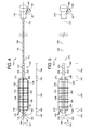
- FIG. 4 illustrates a second example catheter 110.
- the catheter 110 is similar to the first example catheter 10 described above, except as indicated below.
- the catheter 110 includes an elongate shaft 112 extending between a proximal end 114 and a distal end 116.
- a longitudinal axis 115 extends from the proximal end 114 to the distal end 116.
- a hub 118 is disposed on the proximal end 114 and includes sidearm 120 and connector 122.
- a balloon 124 is attached to a distal portion of the elongate shaft 112 adjacent the distal end 116.
- the balloon 124 defines an interior chamber 126 and has uninflated and inflated configurations.
- FIG. 4 illustrates the balloon 124 in the inflated configuration.
- a textile sleeve 128 is secured to the balloon 124 and surrounds the balloon 124.
- the textile sleeve 128 comprises a plurality of warp threads 130 extending along the longitudinal axis 115 and at least one weft thread 132 extending circumferentially around the longitudinal axis 115.
- the longitudinal axis 115 of the catheter 110 is also a longitudinal axis of the balloon 124 and a longitudinal axis of the textile sleeve 128.
- the elongate shaft 112 comprises a main body 140 that extends along the entire length of the elongate shaft 112, from the proximal end 114 to the distal end 116.
- the main body 140 is a solid member that defines an inflation lumen 142 that extends along an axial length of the elongate shaft 112.
- the inflation lumen 142 is in communication with the interior chamber 126 of the balloon 124 and a port lumen 144 defined by the sidearm 120.
- the balloon 124 is attached to elongate member 112 at proximal junction 146 and distal junction 148.
- the balloon 124 has a balloon proximal end 150 and a balloon distal end 152.
- the balloon 124 has a proximal neck 154 and a distal neck 156, each of which is closely fit to the outer circumference of the elongate member 112.
- the balloon 124 has a body 158 that has the maximum outer diameter of the balloon 124 when in the inflated configuration.
- a proximal cone 160 transitions from the proximal neck 154 to the body 158 and a distal cone 162 transitions from the distal neck 156 to the body 158.
- the weft thread 132 of the textile sleeve 128 defines a series of circumferential loops that extend around the longitudinal axis 115 of the elongate member 112 and indeed around the balloon 112 and/or the elongate member 112.
- the portion of the textile sleeve 128 that is secured to the proximal neck 154 portion of the balloon 124 includes a series of circumferential loops 174, each of which is a partial circumferential loop that includes two free ends.
- the free ends of the series of circumferential loops 174 forms a gap 182 in the portion of the textile sleeve 128 secured to the proximal neck 154 of the balloon 124.
- the portion of the textile sleeve 128 that is secured to the distal neck 156 portion of the balloon 124 includes a series of circumferential loops 178, each of which is a partial circumferential loop that includes two free ends.
- the free ends of the series of circumferential loops 178 forms a gap 184 in the portion of the textile sleeve 128 secured to the distal neck 156 of the balloon 124.
- each knot 180 can be formed after cutting an extended weft loop and forming the knot 180 with the ends created by the cutting.
- knots in the portions of the textile sleeve 128 that are secured to the body 158, proximal cone 160 and distal cone 162 portions of the balloon 124, while leaving gaps 182, 184 in the portions of the textile sleeve 128 secured to the proximal neck 154 and distal neck 156 portions of the balloon 124, respectively, may be advantageous.
- Inclusion on knots in this manner provides more strength for reinforcement in the area where the balloon experiences the most stress during use. Such strength is not necessary in the proximal and distal neck portions, where removal of excess textile material can be desirable for attachment of the balloon to underlying materials.
- FIG. 5 illustrates a third example catheter 210.
- the catheter 210 is similar to the first example catheter 10 described above, except as indicated below.
- the catheter 210 includes an elongate shaft 212 extending between a proximal end 214 and a distal end 216.
- a longitudinal axis 215 extends from the proximal end 214 to the distal end 216.
- a hub 218 is disposed on the proximal end 214 and includes sidearm 220 and connector 222.
- a balloon 224 is attached to a distal portion of the elongate shaft 212 adjacent the distal end 216.
- the balloon 224 defines an interior chamber 226 and has uninflated and inflated configurations.
- FIG. 5 illustrates the balloon 224 in the inflated configuration.
- a textile sleeve 228 is secured to the balloon 224 and surrounds the balloon 224.
- the textile sleeve 228 comprises a plurality of warp threads 230 extending along the longitudinal axis 215 and at least one weft thread 232 extending circumferentially around the longitudinal axis 215.
- the longitudinal axis 215 of the catheter 210 is also a longitudinal axis of the balloon 224 and a longitudinal axis of the textile sleeve 228.
- the elongate shaft 212 comprises a main body 240 that extends along the entire length of the elongate shaft 212, from the proximal end 214 to the distal end 216.
- the main body 240 is a solid member that defines an inflation lumen 242 that extends along an axial length of the elongate shaft 212.
- the inflation lumen 242 is in communication with the interior chamber 226 of the balloon 224 and a port lumen 244 defined by the sidearm 220.
- the balloon 224 is attached to elongate member 212 at proximal junction 246 and distal junction 248.
- the balloon 224 has a balloon proximal end 250 and a balloon distal end 252.
- the balloon 224 has a proximal neck 254 and a distal neck 256, each of which is closely fit to the outer circumference of the elongate member 212.
- the balloon 224 has a body 258 that has the maximum outer diameter of the balloon 224 when in the inflated configuration.
- a proximal cone 260 transitions from the proximal neck 254 to the body 258 and a distal cone 262 transitions from the distal neck 256 to the body 258.
- the weft thread 232 of the textile sleeve 228 defines a series of circumferential loops that extend around the longitudinal axis 215 of the elongate member 212 and indeed around the balloon 212 and/or the elongate member 212.
- the portion of the textile sleeve 228 that is secured to the proximal neck 254 portion of the balloon 224 includes a series of circumferential loops 274, each of which is a partial circumferential loop that includes two free ends.
- the free ends of the series of circumferential loops 274 forms a gap 282 in the portion of the textile sleeve 228 secured to the proximal neck 254 of the balloon 224.
- the portion of the textile sleeve 228 that is secured to the distal neck 256 portion of the balloon 224 includes a series of circumferential loops 278, each of which is a partial circumferential loop that includes two free ends.
- the free ends of the series of circumferential loops 278 forms a gap 284 in the portion of the textile sleeve 228 secured to the distal neck 256 of the balloon 224.
- the circumferential loops 272 of the portion of the textile sleeve 228 that is secured to the proximal cone 260 portion of the balloon 224 include a series of circumferential loops, each of which is a partial circumferential loop that includes two free ends.
- the free ends of the series of circumferential loops 272 forms a gap 286 in the portion of the textile sleeve 228 secured to the proximal cone 260 of the balloon 224.
- the circumferential loops 276 of the portion of the textile sleeve 228 that is secured to the distal cone 262 portion of the balloon 224 include a series of circumferential loops, each of which is a partial circumferential loop that includes two free ends. The free ends of the series of circumferential loops 276 forms a gap 288 in the portion of the textile sleeve 228 secured to the distal cone 262 of the balloon 224.
- each knot 280 can be formed after cutting an extended weft loop and forming the knot 280 with the ends created by the cutting.
- this structural arrangement may be suitable for use in a catheter having a balloon with a body portion that is non-compliant or that has relatively low compliance compared to other portions of the balloon, and that has one or more compliant cone portions.
- All components of a catheter according to an embodiment can be made from any suitable material. Skilled artisans will be able to select appropriate materials for the components of a catheter according to a particular embodiment based on various considerations, including the nature of the body vessel within which the particular catheter is intended to be used. Examples of suitable materials include, but are not limited to, plastics and other materials currently used in the manufacture of conventional catheters, and newly-developed materials determined to be suitable for use in components of medical catheters.
- the balloon component of a catheter according to an embodiment can be formed of any suitable material, and skilled artisans will be able to select a suitable material for a balloon in a catheter according to a particular embodiment based on various considerations, including the material(s) that form the elongate member in the catheter.
- Example materials considered suitable to form a balloon include, but are not limited to, biocompatible materials, materials that can be made biocompatible, flexible materials, substantially flexible materials, polymers, Pebax (Pebax is a registered trademark of Ato Chimie Corporation of Allee des Vosges, Courbevoie, France), nylon, polyethylene, polyurethane, other materials currently considered suitable for use as a balloon component in a medical catheter, and newly-developed materials determined to be suitable for use as a balloon component in a medical catheter.
- balloon 24 can comprise any suitable type of balloon, such as a compliant balloon, a non-compliant balloon, any other type of balloon currently considered suitable for use in a medical catheter, and any newly-developed type of balloon determined to be suitable for use in a medical catheter.
- the textile sleeve component of a catheter according to an embodiment can be formed of any suitable material, and skilled artisans will be able to select a suitable material for a textile sleeve in a catheter according to a particular embodiment based on various considerations, including the material(s) that form the balloon in the catheter.
- Example materials considered suitable to form a textile sleeve include, but are not limited to, biocompatible materials, materials that can be made biocompatible, natural materials and synthetic materials. Examples of suitable materials include polyester threads, polyethylene threads, nylon threads, metallic wires, silk threads, and plastic threads. Threads formed of ultra high molecular weight polyethylene are also considered suitable.
- Threads formed of polytetrafluoroethylene (PTFE), threads formed of polyetheretherketone (PEEK), and threads formed of polyetherketoneketone (PEKK) are also considered suitable.
- threads having a monofilament structure and threads having a multifilament structure are considered suitable.
- a textile sleeve can include threads that comprise the same or different materials and the same or different structures.
- a textile sleeve can have warp and weft threads that comprise the same material or that comprise different materials and that have the same structure or that have different structures.
- the textile sleeve component of a catheter according to an embodiment can have any suitable structure prior to being secured to a balloon during the making of the catheter, and skilled artisans will be able to select a suitable structure for a textile sleeve for inclusion in a catheter according to a particular embodiment based on various considerations, including any desired final structure of the textile sleeve relative to the balloon component of the catheter.
- a textile sleeve that has a localized density of circumferential loops defined by one or more weft threads that is lower in the area or areas along the longitudinal axis of the textile sleeve in which it is desired to reduce the cross-sectional diameter of the textile sleeve during the making of the catheter, as compared to a localized density of circumferential loops in another area or other areas along the longitudinal axis of the textile sleeve, is suitable for making catheters, such as the example catheters described and illustrated herein.
- FIG. 6 illustrates an example textile sleeve 310 useful in the making of a catheter.
- the textile sleeve 310 is a circumferential body forming an interior cavity 311 that can receive a balloon or balloon precursor during the making of a catheter.
- the textile sleeve 310 includes a plurality of warp threads 312 extending along, parallel to, or substantially parallel to the longitudinal axis 315 and at least one weft thread 314 extending circumferentially around the longitudinal axis 315.
- the textile sleeve 310 defines a proximal opening 316 and an opposite distal opening 318, each of which provides access into the interior cavity 311.
- the textile sleeve 310 has a body portion 320 that extends along a portion of the longitudinal axis 315 and that has the largest outer diameter of the textile sleeve 310. Also, the textile sleeve 310 includes proximal 322 and distal 324 neck portions, which define the proximal 316 and distal 318 openings, respectively, and proximal 326 and distal 328 cone portions, each of which transitions from the relatively large outer diameter of the body portion 320 to the relatively small outer diameter of the respective proximal 322 and distal 324 neck portions.
- the textile sleeve 310 includes localized weft densities, represented as picks per inch, that make the textile sleeve 310 suitable for use in the methods of making catheters described herein.
- the textile sleeve 310 has a weft density extending along the body portion 320 that is greater than the weft density that extends along each of the proximal neck 322, distal neck 324, proximal cone 326 and distal cone 328 portions of the textile sleeve 310.
- a textile sleeve according to an embodiment can have a weft density extending along the body portion of the textile sleeve that is greater than one or more of the proximal neck, distal neck, proximal cone, and distal cone portions of the textile sleeve.
- a textile sleeve according to an embodiment can have any suitable relative weft densities between the body and one or more of the proximal neck, distal neck, proximal cone and distal cone portions of the textile sleeve, and a skilled artisan will be able to select suitable relative and actual weft densities for the various portions of a textile sleeve according to a particular embodiment based on various considerations, including the overall size of the textile sleeve, the composition of the warp and weft threads, and any requirements or considerations of a method of making a catheter in which the textile sleeve is intended to be used.
- a ratio of weft densities for a body portion of a textile sleeve to one or more other portions of a textile sleeve that is a proximal neck, distal neck, proximal cone or distal cone of the textile sleeve that is between about 10 to 1 and about 2 to 1 is suitable for use in the methods of making a catheter described below.
- a ratio of weft densities for a body portion of a textile sleeve to one or more other portion(s) of a textile sleeve that is a proximal neck, distal neck, proximal cone or distal cone of the textile sleeve that is between about 8 to 1 and about 2 to 1 is suitable for use in the methods of making a catheter described below.
- a ratio of weft densities for a body portion of a textile sleeve to one or more other portions of a textile sleeve that is a proximal neck, distal neck, proximal cone or distal cone of the textile sleeve that is between about 6 to 1 and about 2 to 1 is suitable for use in the methods of making a catheter described below.
- a ratio of weft densities for a body portion of a textile sleeve to one or more other portions of a textile sleeve that is a proximal neck, distal neck, proximal cone or distal cone of the textile sleeve that is between about 8 to 1 and about 5 to 1 is suitable for use in the methods of making a catheter described below.
- a ratio of weft densities for a body portion of a textile sleeve to one or more other portions of a textile sleeve that is a proximal neck, distal neck, proximal cone or distal cone of the textile sleeve that is between about 4 to 1 and about 2 to 1 is suitable for use in the methods of making a catheter described below.
- a ratio of weft densities for a body portion of a textile sleeve to one or more other portions of a textile sleeve that is a proximal neck, distal neck, proximal cone or distal cone of the textile sleeve that is between about 3 to 1 and about 2 to 1 is suitable for use in the methods of making a catheter described below.
- a ratio of weft densities for a body portion of a textile sleeve to one or more other portions of a textile sleeve that is a proximal neck, distal neck, proximal cone or distal cone of the textile sleeve that is about 5 to 1 is suitable for use in the methods of making a catheter described below.
- a ratio of weft densities for a body portion of a textile sleeve to one or more other portions of a textile sleeve that is a proximal neck, distal neck, proximal cone or distal cone of the textile sleeve that is about 4 to 1 is suitable for use in the methods of making a catheter described below.
- a ratio of weft densities for a body portion of a textile sleeve to one or more other portions of a textile sleeve that is a proximal neck, distal neck, proximal cone or distal cone of the textile sleeve that is about 3 to 1 is suitable for use in the methods of making a catheter described below.
- a ratio of weft densities for a body portion of a textile sleeve to one or more other portions of a textile sleeve that is a proximal neck, distal neck, proximal cone or distal cone of the textile sleeve that is about 2 to 1 is suitable for use in the methods of making a catheter described below.
- the inventors have determined that a textile sleeve having a body portion with a weft density of about 130 picks per inch and proximal and distal neck portions with a weft density of about 40 picks per inch is suitable for use in the methods of making a catheter described herein.
- a textile sleeve can have a warp density, represented as ends per inch, that varies at any point along the width of the textile sleeve, measured orthogonally or substantially orthogonally to the longitudinal axis of the textile sleeve.
- FIG. 7 illustrates an example textile sleeve 410 useful in the making of a catheter.
- the textile sleeve 410 is a circumferential body forming an interior cavity 411 that can receive a balloon or balloon precursor during the making of a catheter.
- the textile sleeve 410 includes a plurality of warp threads 412 extending along, parallel to, or substantially parallel to the longitudinal axis 415 and at least one weft thread 414 extending circumferentially around the longitudinal axis 415.
- the textile sleeve 410 defines a proximal opening 416 and an opposite distal opening 418, each of which provides access into the interior cavity 411.
- the textile sleeve 410 has a body portion 420 that extends along a portion of the longitudinal axis 415 and that has the largest outer diameter of the textile sleeve 410.
- the textile sleeve 410 includes proximal 422 and distal 424 neck portions, which define the proximal 416 and distal 418 openings, respectively, and proximal 426 and distal 428 cone portions, each of which transitions from the relatively large outer diameter of the body portion 420 to the relatively small outer diameter of the respective proximal 422 and distal 424 neck portions.
- the textile sleeve 410 includes a localized warp density that makes the textile sleeve 410 suitable for use in the methods of making catheters described herein.
- the textile sleeve 410 has a lower warp density across the width y' of the proximal neck portion 422 and the distal neck portion 424, referred to as the neck portions warp density, than the warp density across the width y of the body portion, referred to as the body warp density, and the varying widths of the proximal cone portion 426 and the distal cone portion 428, referred to as the cone warp density.
- the warp density across the width y' of the proximal neck 422 and distal neck 424 portions extends through the central portion of the proximal cone 426, distal cone 428, and body 420 portions, while the peripheral portions of the proximal cone 426, distal cone 428, and body 420 portions have higher warp densities, giving these portions higher overall warp densities than those of the proximal neck 422 and distal neck 424 portions.
- any suitable relative warp densities can be used, it is noted that a warp density ratio of between about 2:1 and about 1:1 of the body warp density to the neck portions warp density is considered suitable.
- the inventors have determined that a warp density of about or exactly 83 ends per inch in the body portion and a warp density of about or exactly 63 ends per inch in the neck portions provides a suitable structure.
- a catheter according to an embodiment can be made in any suitable manner and using any suitable technique. Skilled artisans will be able to select an appropriate technique for making a catheter according to a particular embodiment based on various considerations, including the nature of the materials used for the various components.
- FIG. 8 is a flowchart representation of an example method 500 of making a catheter.
- the steps of the method 500 can be performed in any suitable order and no order is implied by the order described below and/or illustrated in the figure, except where an explicit reference is made to another step.
- An initial step 510 of the method 500 comprises placing a textile sleeve on a mandril.
- the textile sleeve can comprise any suitable textile sleeve, including those described herein.
- the mandril can comprise any suitable mandril, including a metal rod, a plastic rod, and an elongate member that is a component of a catheter or a precursor of a component of a catheter.
- Another step 512 comprises engaging a weft thread of the textile sleeve with a tool.
- Any suitable tool can be used to perform this step, including a finger or fingers, a needle and any other suitable tool.
- any suitable technique for engaging a weft thread with a tool can be used, and the technique need only result in making contact between the tool and the weft thread that enables the moving step 514 described below.
- the tool comprises a needle
- this step 512 can be accomplished by placing the needle between a selected weft thread and other weft and warp threads such that the moving step 514 can be performed. It is believed to be advantageous to perform this step 512 by engaging only a single weft thread.
- FIG. 9A illustrates an example textile sleeve 610 disposed on a mandril 612. A needle 614 is engaged with a single weft thread 616 after performance of step 512.
- Another step 514 comprises moving the engaged weft thread away from the remainder of the textile sleeve to form an extended weft loop.
- This step can be performed in any suitable manner. For example, a force can be applied to the tool used in the engaging step 512 to cause it to move away from the textile sleeve and mandril such that an extended weft loop is formed.
- FIG 9B shows an extended weft loop 618 after performance of this step 514.
- This step 514 can be performed to any suitable degree, typically measured by the size of the extended weft loop or the ability to continue moving the engaged weft thread away from the textile sleeve and the mandril.
- the inventors have determined that it is suitable to continue the moving of this step 514 until the engaged weft thread prevents further moving, typically due to being reduced to the smallest possible circumferential loop or circumferential loops around the mandril. Also, if it is desirable in a particular method to have loose ends formed in the extended weft loop, such as in the example catheters described above, the inventors have determined that it is suitable to continue this moving step 514, if possible, until the engaged weft thread breaks and the loose ends are formed.
- FIG. 9B illustrates the example textile sleeve 610 after the engaged weft thread 616 has been moved away from the remainder of the textile sleeve 610.
- An extended weft loop 618 has formed as a result of the movement.
- the step 512 of engaging a weft thread and the step 514 of moving the engaged weft thread away from the textile sleeve can be repeated a desired number of times, engaging a different weft thread or a different portion of a weft thread with each performance of the steps 512, 514 to produce a desired number of extended weft loops.
- the step 514 of moving the engaged weft thread away from the remainder of the textile sleeve can produce a longitudinal gap in the textile sleeve as the extended weft loop or extended weft loops are formed. If the presence of a longitudinal gap is undesirable in the catheter being made, an optional step 516 or manipulating the textile sleeve to remove the longitudinal gap can be performed. If included, this step 516 can be performed using any suitable technique. A skilled artisan will be able to select a suitable technique for a particular method based on various considerations, including the nature of the material or materials of the textile sleeve.
- the inventors have determined that a simple digital manipulation of the warp and/or weft threads of the textile sleeve near and/or around the longitudinal gap is typically sufficient to remove a longitudinal gap or reduce a longitudinal gap to an acceptable size, configuration, and/or orientation.
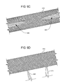
- FIG. 9C illustrates the example textile sleeve 610 after multiple weft threads have been engaged and moved away from the remainder of the textile sleeve 610 through repetition of steps 512 and 514.
- a longitudinal gap 620 has formed as a result of the movement.
- FIG. 9D illustrates the example textile sleeve 610 after the optional step 516 or manipulating the textile sleeve 610 to remove the longitudinal gap has been performed.
- Multiple extended weft loops 618, 622 are present as a result of engaging and moving multiple weft threads, and the longitudinal gap has been removed.
- Another step 518 comprises manipulating one or more extended weft loops.
- This step can be performed to place the extended weft loop(s) in a suitable configuration for the step 520 of securing the textile sleeve to the balloon, described below.
- Any suitable technique can be used to perform this step, and a skilled artisan will be able to select an appropriate technique based on various considerations, including any desired final structure for the balloon catheter being made, such as the example structures described herein, and any general or localized strength considerations of the balloon catheter being made.
- suitable techniques for performing this step 518 include cutting the extended weft loop(s) to create free ends of the weft thread that can be knotted to each other or secured to the balloon as free ends, wrapping the extending weft loop(s) around a portion or portions of the textile sleeve to form a wrapped extended weft loop(s) that can be secured to the balloon, and weaving the extended weft loop(s), or one, at least one, or both of the free ends, back into the textile sleeve.
- any suitable combination of these and/or other techniques can be used when manipulating multiple extended weft loops in a particular method. Indeed, as described above, it may be desirable to use different techniques to produce a catheter having different structure resulting from manipulation of extended weft loops at different locations on the balloon/textile sleeve portion of the catheter.
- step 518 of manipulating one or more extended weft loops can be performed to place the extended weft loop(s) in a suitable configuration for the step 520 of securing the textile sleeve to the balloon, no specific order of these two steps is required.
- the step 518 can be performed prior to, during, or after step 520 is performed.
- the step 518 can be performed by wrapping extending weft loop(s) around a portion or portions of the textile sleeve to form a wrapped extended weft loop(s).
- Step 520 can then be performed to secure the textile sleeve to the balloon, such as by fusing the textile sleeve to the balloon.
- step 520 can be performed to secure the textile sleeve to the balloon, such as by applying a suitable coating to the textile sleeve and balloon assembly.
- step 518 can be performed, such as by cutting the extended weft loop(s) to create free ends of the weft thread that can then be knotted to each other, left as free ends, or further secured to the balloon.
- Another step 520 comprises securing the textile sleeve to a balloon usable in a balloon catheter.
- Any suitable technique can be used for performing this step, and a skilled artisan will be able to select an appropriate technique for a particular method based on various considerations, including the nature of the material of the balloon and of the textile sleeve. Examples of suitable techniques include placing the balloon or a balloon precursor within the interior chamber of the textile sleeve and heating the balloon or balloon precursor and textile sleeve to fuse the elements together. If a balloon precursor is used, it can be inflated as part of this step as well.
- Another example includes applying an adhesive to the balloon or a balloon precursor and/or the textile sleeve to adhere the balloon or balloon precursor and textile sleeve elements to each other.
- the balloon or a balloon precursor can be attached to a catheter prior to performance of this step such that performance of this step completes the making of a balloon catheter, or the balloon or a balloon precursor can be separate from an elongate member of a catheter such that another step of securing the balloon or a balloon precursor and the textile sleeve secured to it to an elongate member of a catheter such that a balloon catheter is produced can be included.
- FIG. 10 is a flowchart representation of another example method 700 of making a catheter.
- An initial step 710 of the method 700 comprises placing a balloon precursor on a mandril.
- the balloon precursor can be a parison suitable for use in a blow molding process to form a final balloon shape.
- Another step 712 comprises passing a textile sleeve over the balloon precursor such that the balloon precursor is disposed within the interior cavity defined by the textile sleeve.
- the textile sleeve can comprise any suitable textile sleeve, including those described herein.
- the mandril can comprise any suitable mandril, including a metal rod, a plastic rod, and an elongate member that is a component of a catheter or a precursor of a component of a catheter.
- Another step 714 comprises engaging a weft thread of the textile sleeve with a tool.
- Any suitable tool can be used to perform this step, including a finger or fingers, a needle and any other suitable tool.
- any suitable technique for engaging a weft thread with a tool can be used, and the technique need only result in making contact between the tool and the weft thread that enables the moving step 716 described below.
- the tool comprises a needle
- this step 714 can be accomplished by placing the needle between a selected weft thread and other weft and warp threads such that the moving step 716 can be performed. It is believed to be advantageous to perform this step 714 by engaging only a single weft thread.
- Another step 716 comprises moving the engaged weft thread away from the remainder of the textile sleeve to form an extended weft loop.
- This step can be performed in any suitable manner. For example, a force can be applied to the tool used in the engaging step 714 to cause it to move away from the textile sleeve and mandril such that an extended weft loop is formed.
- This step 716 can be performed to any suitable degree, typically measured by the size of the extended weft loop or the ability to continue moving the engaged weft thread away from the textile sleeve and the mandril.
- the inventors have determined that it is suitable to continue the moving of this step 716 until the textile sleeve is "necked down" onto the balloon precursor such that the textile sleeve is secured to the balloon precursor at the point at which the extended weft loop has been formed. This secures these elements together at this point but leaves the balloon precursor free of the textile sleeve at other points, such as within the cavity of the textile sleeve. Also, if it is desirable in a particular method to have loose ends formed in the extended weft loop, such as in the example catheters described above, the inventors have determined that it is suitable to continue this moving step 716, if possible, until the engaged weft thread breaks and the loose ends are formed.
- the step 714 of engaging a weft thread and the step 716 of moving the engaged weft thread away from the textile sleeve can be repeated a desired number of times, engaging a different weft thread or a different portion of a weft thread with each performance of the steps 714, 716 to produce a desired number of extended weft loops.
- the step 716 of moving the engaged weft thread away from the remainder of the textile sleeve can produce a longitudinal gap in the textile sleeve as the extended weft loop or extended weft loops are formed. If the presence of a longitudinal gap is undesirable in the catheter being made, an optional step 718 or manipulating the textile sleeve to remove the longitudinal gap can be performed. If included, this step 718 can be performed using any suitable technique. A skilled artisan will be able to select a suitable technique for a particular method based on various considerations, including the nature of the material or materials of the textile sleeve.
- the inventors have determined that a simple digital manipulation of the warp and/or weft threads of the textile sleeve near and/or around the longitudinal gap is typically sufficient to remove a longitudinal gap or reduce a longitudinal gap to an acceptable size, configuration, and/or orientation.
- Another step 720 comprises manipulating one or more extended weft loops. This step can be performed to place the extended weft loop(s) in a suitable configuration for the step 722 of securing the textile sleeve to the balloon, described below. Any suitable technique can be used to perform this step, and a skilled artisan will be able to select an appropriate technique based on various considerations, including any desired final structure for the balloon catheter being made, such as the example structures described herein, and any general or localized strength considerations of the balloon catheter being made.
- Examples of suitable techniques for performing this step 720 include cutting the extended weft loop(s) to create free ends of the weft thread that can be knotted to each other or secured to the balloon as free ends, wrapping the extending weft loop(s) around a portion or portions of the textile sleeve to form a wrapped extended weft loop(s) that can be secured to the balloon, and weaving the extended weft loop(s), or one, at least one, or both of the free ends, back into the textile sleeve.
- any suitable combination of these and/or other techniques can be used when manipulating multiple extended weft loops in a particular method. Indeed, as described above, it may be desirable to use different techniques to produce a catheter having different structure resulting from manipulation of extended weft loops at different locations on the balloon/textile sleeve portion of the catheter.
- step 720 of manipulating one or more extended weft loops can be performed to place the extended weft loop(s) in a suitable configuration for the step 724 of securing the textile sleeve to the balloon, no specific order of these two steps is required.
- the step 720 can be performed prior to, during, or after step 724 is performed.
- the step 720 can be performed by wrapping extending weft loop(s) around a portion or portions of the textile sleeve to form a wrapped extended weft loop(s).
- Step 724 can then be performed to secure the textile sleeve to the balloon, such as by fusing the textile sleeve to the balloon.
- step 724 can be performed to secure the textile sleeve to the balloon, such as by applying a suitable coating to the textile sleeve and balloon assembly.
- step 720 can be performed, such as by cutting the extended weft loop(s) to create free ends of the weft thread that can then be knotted to each other, left as free ends, or further secured to the balloon.
- Another step 722 comprises transforming the balloon precursor into a balloon suitable for use in a balloon catheter.
- Any suitable technique can be used for performing this step, and a skilled artisan will be able to select an appropriate technique for a particular method based on various considerations, including the nature of the material of the balloon precursor. Examples of suitable techniques include placing the assembly of the balloon precursor and textile sleeve into a cavity of a blow mold and then inflating the balloon precursor in a blow molding process, effectively forming the balloon and forcing the material of the balloon precursor into direct contact with the textile sleeve during the molding process.
- Another step 724 comprises securing the textile sleeve to the balloon.
- This step 724 can be accomplished using any suitable technique, process and materials. Furthermore, this step 724 can be performed during or subsequent to the performance of step 722. For example, the use of adhesives and/or the application of heat during performance of step 722 can facilitate the securement of the textile sleeve to the balloon as it is being formed from the balloon precursor.
- the balloon precursor can be attached to a catheter prior to performance of the method step such that performance step 724 completes the making of a balloon catheter, or the balloon precursor can be separate from an elongate member of a catheter such that another step 726 of securing either the balloon precursor, balloon precursor and textile sleeve assembly, or the balloon and textile sleeve assembly to an elongate member of a catheter such that a balloon catheter is produced can be included.
- An example catheter includes an elongate shaft and a balloon movable between uninflated and inflated configurations, and a textile sleeve secured to the balloon.
- the textile sleeve has a plurality of warp threads and at least one weft thread extending circumferentially around the balloon.
- circumferential loops in the portion of the textile sleeve that is secured to the body of the balloon are larger in diameter than circumferential loops in the portion of the textile sleeve that is secured to one or more of the proximal neck, distal neck, proximal cone and distal cone portions of the balloon.
- This difference in diameter may be arranged by effecting that a circumferential loop in the portion of the textile sleeve that is secured to one or more of the proximal neck, distal neck, proximal cone and distal cone portions of the balloon is discontinuous. This may be achieved through moving a weft thread away from the remainder of the textile sleeve to form an extended weft loop which can then be manipulated in a manner as to reduce the diameter of the corresponding portion of the textile sleeve.
- the extended loop may for example be cut to form ends which may be free or may be secured to each other or to the sleeve or to the balloon.
- the extended loop may in another example not be cut and may for example be wrapped around the textile sleeve.
Landscapes
- Health & Medical Sciences (AREA)
- Heart & Thoracic Surgery (AREA)
- Life Sciences & Earth Sciences (AREA)
- Engineering & Computer Science (AREA)
- Biomedical Technology (AREA)
- General Health & Medical Sciences (AREA)
- Biophysics (AREA)
- Anesthesiology (AREA)
- Child & Adolescent Psychology (AREA)
- Hematology (AREA)
- Animal Behavior & Ethology (AREA)
- Pulmonology (AREA)
- Public Health (AREA)
- Veterinary Medicine (AREA)
- Textile Engineering (AREA)
- Vascular Medicine (AREA)
- Manufacturing & Machinery (AREA)
- Media Introduction/Drainage Providing Device (AREA)
Abstract
Description
- The disclosure relates to medical devices. More particularly, the disclosure relates to balloon catheters useful in intraluminal treatment procedures on animals, such as human beings, components useful in the making of catheters, and methods of making catheters.
- In the pursuit of catheters having expandable balloons with higher rated burst pressures and relatively thin wall thicknesses, artisans have developed catheters that include a textile component. While the development of textile-reinforced high-pressure balloon catheters has provided desirable balloon performance characteristics, the inclusion of textiles has introduced new challenges to the manufacturing of balloon catheters. As a result, a need remains for new textile balloon catheters and methods of making textile balloon catheters.
- Catheters, catheter components, and methods of making catheters are described.
- An example catheter comprises an elongate member having a proximal end, a distal end, a main body extending between the proximal end and the distal end, and a longitudinal axis, the main body defining a lumen; a balloon having uninflated and inflated configurations, the balloon secured to the elongate member and defining an interior chamber in communication with the lumen such that movement of fluid from the lumen into the interior chamber moves the balloon from the uninflated configuration to the inflated configuration and movement of fluid from the interior chamber of the balloon into the lumen moves the balloon from the inflated configuration to the uninflated configuration; the balloon having balloon proximal and balloon distal neck portions secured to the elongate member, a balloon body portion disposed between the balloon proximal and balloon distal neck portions and defining a maximum outer diameter of the balloon when the balloon is in the inflated configuration, a balloon proximal cone portion disposed between the balloon body portion and the balloon proximal neck portion, and a balloon distal cone portion disposed between the balloon body portion and the balloon distal neck portion; and a textile sleeve secured to the balloon, the textile sleeve having a textile sleeve body portion disposed on the balloon body portion, a textile sleeve proximal neck portion disposed on the balloon proximal neck portion, and a textile sleeve distal neck portion disposed on the balloon distal neck portion. The textile sleeve comprises a warp thread and at least one weft thread, the at least one weft thread defining a first set of circumferential loops in the textile sleeve body portion and a second set of circumferential loops in the textile sleeve proximal neck portion. A circumferential loop of the second set of circumferential loops extends only partially around the balloon proximal neck portion.
- Another example catheter comprises an elongate member having a proximal end, a distal end, a main body extending between the proximal end and the distal end, and a longitudinal axis, the main body defining a lumen; a balloon having uninflated and inflated configurations, the balloon secured to the elongate member and defining an interior chamber in communication with the lumen such that movement of fluid from the lumen into the interior chamber moves the balloon from the uninflated configuration to the inflated configuration and movement of fluid from the interior chamber of the balloon into the lumen moves the balloon from the inflated configuration to the uninflated configuration; the balloon having balloon proximal and balloon distal neck portions secured to the elongate member, a balloon body portion disposed between the balloon proximal and balloon distal neck portions and defining a maximum outer diameter of the balloon when the balloon is in the inflated configuration, a balloon proximal cone portion disposed between the balloon body portion and the balloon proximal neck portion, and a balloon distal cone portion disposed between the balloon body portion and the balloon distal neck portion; and a textile sleeve secured the balloon, the textile sleeve having a textile sleeve body portion disposed on the balloon body portion, a textile sleeve proximal neck portion disposed on the balloon proximal neck portion, and a textile sleeve distal neck portion disposed on the balloon distal neck portion. The textile sleeve comprises a warp thread and at least one weft thread, the at least one weft thread defining a first set of circumferential loops in the textile sleeve body portion and a second set of circumferential loops in the textile sleeve proximal neck portion. A circumferential loop of the second set of circumferential loops includes two free ends of the at least one weft thread knotted together.
- Another example catheter comprises an elongate member having a proximal end, a distal end, a main body extending between the proximal end and the distal end, and a longitudinal axis, the main body defining a lumen; a balloon having uninflated and inflated configurations, the balloon secured to the elongate member and defining an interior chamber in communication with the lumen such that movement of fluid from the lumen into the interior chamber moves the balloon from the uninflated configuration to the inflated configuration and movement of fluid from the interior chamber of the balloon into the lumen moves the balloon from the inflated configuration to the uninflated configuration; the balloon having balloon proximal and balloon distal neck portions secured to the elongate member, a balloon body portion disposed between the balloon proximal and balloon distal neck portions and defining a maximum outer diameter of the balloon when the balloon is in the inflated configuration, a balloon proximal cone portion disposed between the balloon body portion and the balloon proximal neck portion, and a balloon distal cone portion disposed between the balloon body portion and the balloon distal neck portion; and a textile sleeve secured the balloon, the textile sleeve having a textile sleeve body portion disposed on the balloon body portion, a textile sleeve proximal neck portion disposed on the balloon proximal neck portion, and a textile sleeve distal neck portion disposed on the balloon distal neck portion. The textile sleeve comprises a warp thread and at least one weft thread, the at least one weft thread defining a first set of circumferential loops in the textile sleeve body portion and a second set of circumferential loops in the textile sleeve proximal neck portion. A circumferential loop of the second set of circumferential loops forms an extended weft loop that is wrapped around the textile sleeve.
- An example method of making a catheter comprises placing a textile sleeve having a plurality of warp threads and at least one weft thread on a mandril; engaging a weft thread of the textile sleeve with a tool; moving the engaged weft thread away from the remainder of the textile sleeve to form an extended weft loop; manipulating the extended weft loop; securing the textile sleeve to a balloon; and securing the balloon to an elongate member defining a lumen such that movement of fluid through the lumen moves the balloon between inflated an uninflated configurations.
- Another example method of making a catheter comprises securing a textile sleeve having at least one extended weft loop to a balloon; and securing the balloon to an elongate member defining a lumen such that movement of fluid through the lumen moves the balloon between inflated an uninflated configurations.
- Another example method of making a catheter comprises moving a weft thread away from the remainder of a textile sleeve comprising the weft thread to form an extended weft loop; securing the textile sleeve to a balloon; and securing the balloon to an elongate member defining a lumen such that movement of fluid through the lumen moves the balloon between inflated an uninflated configurations.
-
-
FIG. 1 is a perspective view, partially broken away, of a first example catheter. -
FIG. 2 is a side view, partially broken away, of the distal end of the catheter illustrated inFIG. 1 . -
FIG. 3A is a magnified view of a portion of the first example catheter. -
FIG. 3B is a magnified view of a portion of an alternative catheter. -
FIG. 3C is a magnified view of a portion of another alternative catheter. -
FIG. 4 is a perspective view, partially broken away, of a second example catheter. -
FIG. 5 is a perspective view, partially broken away, of a third example catheter. -
FIG. 6 is a top view of an example textile sleeve useful in the making of a catheter. -
FIG. 7 is a top view of a second example textile sleeve useful in the making of a catheter. -
FIG. 8 is a flowchart representation of an example method of making a catheter. -
FIG. 9A is a schematic illustration of a textile sleeve with a weft thread engaged. -
FIG. 9B is a schematic illustration of a textile sleeve with a selected weft thread being moved away from the remainder of the textile sleeve. -
FIG. 9C is a schematic illustration of a textile sleeve after a weft thread has been moved away from the remainder of the textile sleeve. -
FIG. 9D is a schematic illustration of a textile sleeve after formation of two extended weft loops. -
FIG. 10 is a flowchart representation of an example method of making a catheter. - The following detailed description and the appended drawings describe and illustrate various example textile balloon catheters and methods of making textile balloon catheters useful in intraluminal treatment procedures on animals, such as human beings. The description and illustration of these examples are provided to enable one skilled in the art to make and use a catheter. They are not intended to limit the scope of the claims in any manner.
- As used herein, the term "warp thread" refers to a thread in a textile element that extends generally along a longitudinal axis extending from a proximal end to a distal end of the textile element.
- As used herein, the term "weft thread" refers to a thread in a textile element that extends circumferentially, partially circumferentially, helically, partially helically, or otherwise around or partially around a longitudinal axis extending from a proximal end to a distal end of the textile element and is woven with one or more warp threads.
- As used herein, the term "thread" refers to a filament element having a length that is several times greater than its width. The term does not require any particular material or properties.
- As used herein, the term "textile" refers to a woven element comprising warp threads and at least one weft thread.
- As used herein, the term "picks per inch" refers to the linear density of weft thread loops in a referenced axial portion of a textile.
- As used herein, the term "ends per inch" refers to the linear density of warp threads across a width of a textile that lies on a plane disposed orthogonal to the longitudinal axis of the textile.
- As used herein, the term "sleeve" refers to an element that wholly or partially surrounds another element. The term does not require that the element be the radially outermost element in a structure and includes structural arrangements in which the element is radially outward of the surrounded element as well as arrangements in which the element is integrated with the surrounded element.
- As used herein, the term "engaging" refers to an action of making contact between two referenced items that is sufficient to allow one of the items to move the other of the items when a force is applied to it. The term does not require any specific type or duration of contact between the items.
-
FIGS. 1, 2 and3A illustrate anexample catheter 10. Thecatheter 10 includes anelongate shaft 12 extending between aproximal end 14 and adistal end 16. Alongitudinal axis 15 extends from theproximal end 14 to thedistal end 16. Ahub 18 is disposed on theproximal end 14 and includessidearm 20 andconnector 22. Aballoon 24 is attached to a distal portion of theelongate shaft 12 adjacent thedistal end 16. Theballoon 24 defines aninterior chamber 26 and has uninflated and inflated configurations.FIG. 1 illustrates theballoon 24 in the inflated configuration. Atextile sleeve 28 is secured to theballoon 24 and surrounds theballoon 24. Thetextile sleeve 28 comprises a plurality ofwarp threads 30 extending along thelongitudinal axis 15 and aweft thread 32 extending circumferentially around thelongitudinal axis 15. Thelongitudinal axis 15 of thecatheter 10 is also a longitudinal axis of theballoon 24 and a longitudinal axis of thetextile sleeve 28. - The
elongate shaft 12 comprises amain body 40 that extends along the entire length of theelongate shaft 12, from theproximal end 14 to thedistal end 16. Themain body 40 is a solid member that defines aninflation 42 lumen that extends along an axial length of theelongate shaft 12. Theinflation lumen 42 is in communication with theinterior chamber 26 of theballoon 24 and aport lumen 44 defined by thesidearm 20. Passage of fluid through theport 44 andinflation 42 lumens, such as fluid in a syringe or other device secured to theconnector 22, inflates and deflates theballoon 24, moving it between its inflated and deflated configurations. As such, theinflation lumen 42 extends substantially along the entire length of theelongate shaft 12, from theproximal end 14 to a point on thelongitudinal axis 15 of theelongate shaft 12 that lies within theinterior chamber 26 of theballoon 24. - While the
elongate shaft 12 of the illustrated embodiment includes only a single lumen, it is noted that a catheter according to an embodiment can include an elongate member that defines any suitable number of additional lumens having any desired function. For example, a catheter can include a main body that, in addition to an inflation lumen, defines a guidewire lumen that extends along a portion of the longitudinal axis of the catheter or along the entire longitudinal axis, from the proximal end to the distal end. As is known in the art, a guidewire lumen can be included if it is desirable to allow the catheter to be navigated over a guidewire that has been placed within a body vessel of an animal, such as a human being, within which the catheter is to be used. As noted above, a catheter according to a particular embodiment can include a lumen that extends along only a portion of the axial length of the elongate shaft. Thus, a guidewire lumen that extends along only a portion of the elongate shaft can be included in a catheter according to a particular embodiment, adapting that catheter for rapid exchange or short wire uses. - The
inflation lumen 42, and indeed each lumen included in a catheter according to a particular embodiment, can have any suitable cross-sectional shape and configuration and a skilled artisan will be able to select a suitable shape and configuration for each lumen in a catheter according to a particular embodiment based on various considerations, including the intended use of each of the lumens. Also, theinflation lumen 42 and any other included lumen can have any suitable inner diameter or other measurement of cross-sectional size. Furthermore, theinflation lumen 42 and any other included lumens can be arranged within the main body of the elongate shaft in any suitable manner and a skilled artisan will be able to select a suitable arrangement for the lumens in a catheter according to a particular embodiment based on various considerations, including the relative sizes of the lumens and any desired flexibility of the elongate shaft. - While the illustrated
catheter 10 includes an attachedhub 18, it is noted that the inclusion of accessory components, such as theillustrated hub 18, is considered optional. Indeed, an embodiment of a catheter can include only an elongate member, a balloon and a textile sleeve. If inclusion of accessory components is desired, though, for a catheter according to a particular embodiment, any suitable catheter accessory component can be included, such as connectors, ports, valves, other types of hubs, and any other suitable catheter accessory component now known or later developed. - The
balloon 24 is attached to elongatemember 12 between theproximal end 14 and thedistal end 16 of theelongate member 12 atproximal junction 46 anddistal junction 48. Theballoon 24 has a balloonproximal end 50 and a balloondistal end 52. Theballoon 24 has aproximal neck 54 and adistal neck 56, each of which is closely fit to the outer circumference of theelongate member 12. As best illustrated inFIG. 2 , theballoon 24 has abody 58 that has the maximum outer diameter of theballoon 24 when in the inflated configuration. Aproximal cone 60 transitions from theproximal neck 54 to thebody 58 and adistal cone 62 transitions from thedistal neck 56 to thebody 58. The interior surface of theballoon 24 and the portion of the exterior surface ofelongate member 12 disposed withinballoon 24 defineballoon chamber 26 that is adapted to receive a fluid such thatballoon 24 can be moved between a first deflated configuration and second inflated configuration.Balloon 24 is attached to elongatemember 12 such that an opening defined by theelongate member 12 places theinflation lumen 42 in communication withballoon chamber 26. With this structural arrangement,balloon 24 is adapted to move between a first, deflated configuration and a second, inflated configuration as fluid is moved into and out ofballoon chamber 26 via theinflation lumen 42.FIGS. 1 and 2 each illustrate theballoon 24 in the inflated configuration. - A user inflates
balloon 24 by introducing a fluid, such as saline, intoinflation lumen 42 until the fluid passes intoballoon chamber 26. The resulting pressure placed on the inner surface of theballoon 24 by the fluid causes theballoon 24 to inflate and adopt the second, inflated configuration. To move theballoon 24 to the first, deflated configuration, vacuum pressure can be applied toinflation lumen 42 to remove fluid located within theballoon chamber 26, resulting in theballoon 24 collapsing and adopting the first, deflated configuration. - Balloon
proximal junction 46 and balloondistal junction 48 can comprise any suitable attachment betweenelongate member 12 andballoon 24, and skilled artisans will be able to select a suitable attachment between a balloon and an elongate member for a catheter according to a particular embodiment based on various considerations, including the materials forming the elongate member and balloon. Example attachments considered suitable between an elongate member and a balloon include, but are not limited to, attachments formed by heat fusing, using adhesives, mechanical connections, and any other method considered suitable for a particular application. - The
textile sleeve 28 is secured to and surrounds theballoon 24. Thetextile sleeve 28 comprises a plurality ofwarp threads 30 extending along, parallel to, or substantially parallel to thelongitudinal axis 15 and aweft thread 32 extending circumferentially around thelongitudinal axis 15. The illustrated embodiment includes asingle weft thread 32 that is woven with a plurality ofwarp threads 30, but any suitable number of weft threads can be used in a textile sleeve for a catheter according to a particular embodiment. - The
textile sleeve 28 can be secured to theballoon 24 in any suitable manner, and an attachment between thetextile sleeve 28 and theballoon 24 can comprise any suitable attachment. A skilled artisan will be able to select a suitable attachment for a catheter according to a particular embodiment based on various considerations, including the material(s) of the textile sleeve and the balloon. Examples of suitable attachments include, but are not limited to, heat-induced fusion of a balloon and textile sleeve, an adhesive attachment, such as a chemical bond formed by applying an adhesive to a surface of a balloon and/or a surface of a textile sleeve prior to establishing contact between the two elements, or a mechanical bond, such as a bond formed by heating and subsequently cooling a textile sleeve and/or an outer surface of a balloon to allow the two elements to physically connect to each other. Alternatively, a chemical bond formed between an adhesive and thread or balloon material can be used as an attachment between a textile sleeve and a balloon in a particular embodiment. Also, a coating can be applied to a textile sleeve and balloon assembly to secure a textile sleeve to a balloon in a particular embodiment. - As best illustrated in
FIG. 2 , thetextile sleeve 28 in the illustrated embodiment is disposed radially outward of theballoon 24. In this embodiment, the inner surface of thetextile sleeve 28 is secured to the outer surface of theballoon 24. It is noted, though, that the textile sleeve in catheters according to particular embodiments can be integrated with the material that forms the balloon. For example, the textile sleeve and balloon can be heated such that the textile sleeve fuses with the material of the balloon. In these embodiments, some material of the balloon may actually be disposed radially outward of the textile sleeve. For example, some material of the balloon component of a catheter according to these embodiments may be disposed within one or more spaces formed by the weaving of one or more warp threads with one or more weft threads of the textile sleeve component. Indeed, some material of the balloon may extend through these spaces and, ultimately, over a portion of the textile sleeve component. - The
weft thread 32 defines a series of circumferential loops that extend around thelongitudinal axis 15 of theelongate member 12 and indeed around theballoon 12 and/or theelongate member 12. Thecircumferential loops 70 in the portion of thetextile sleeve 28 that is secured to thebody 58 of theballoon 24 are larger in diameter than thecircumferential loops 72 in the portion of thetextile sleeve 28 that is secured to theproximal cone 60. In turn, thecircumferential loops textile sleeve 28 are larger in diameter than thecircumferential loops 74 in the portion of thetextile sleeve 28 that is secured to theproximal neck 54. Thecircumferential loops 70 in the portion of thetextile sleeve 28 that is secured to thebody 58 of theballoon 24 are larger in diameter than thecircumferential loops 76 in the portion of thetextile sleeve 28 that is secured to thedistal cone 62. In turn, thecircumferential loops textile sleeve 28 are larger in diameter than thecircumferential loops 78 in the portion of thetextile sleeve 28 that is secured to thedistal neck 56. - The
circumferential loops FIG. 3A , theweft thread 32 in the portion of thetextile sleeve 28 secured to theproximal neck 54 includes a series ofknots 80. As described in more detail below, eachknot 80 can be formed after cutting an extended weft loop and forming theknot 80 with the ends created by the cutting. Also as described in more detail below, the extended weft loop can be formed by pulling a section of theweft thread 32 until it is drawn tight against theelongate member 12. -
FIG. 3B illustrates an alternative embodiment. The catheter 10' of this alternative embodiment is identical to thecatheter 10 described above, except for having circumferential loops 74' that have a different structure than thecircumferential loops 74 ofcatheter 10. In this embodiment, each of the circumferential loops 74' in the portion of the textile sleeve 28' secured to theproximal neck 54 is a partial circumferential loop and includes two free ends. The free ends of the series of circumferential loops 74' forms a gap 82' in the portion of the textile sleeve 28' secured to theproximal neck 54. As described in more detail below, the series of partial circumferential loops 74' and the gap 82' can be formed after cutting a series of extended weft loops formed in the weft thread 32' tightly against theelongate member 12 and leaving the resulting ends free. In the illustrated embodiment, each of the circumferential loops 74' in the portion of the textile sleeve 28' secured to theproximal neck 54 is a partial circumferential loop and includes two free ends. It is noted, though, that a catheter according to a particular embodiment can have any desired number of circumferential loops having free ends in a portion of a textile sleeve that is secured to a particular portion of a balloon, such as a neck, body or cone portion, and a skilled artisan will be able to select an appropriate number of circumferential loops having free ends based on various considerations, such as the length of the portion of the balloon to which the portion of the textile sleeve is or is to be secured, the material forming the textile sleeve, and other considerations. Examples of suitable numbers of circumferential loops having free ends in a portion of a textile sleeve that is secured to a particular portion of a balloon include all circumferential loops in the portion of the textile sleeve, less than all circumferential loops in the portion of the textile sleeve, one of the circumferential loops in the portion of the textile sleeve, two circumferential loops in the portion of the textile sleeve, a plurality of circumferential loops in the portion of the textile sleeve, three circumferential loops in the portion of the textile sleeve, and more than three circumferential loops in the portion of the textile sleeve. A suitable number of circumferential loops having free ends can be represented as a percentage of all circumferential loops in the portion of the textile sleeve. For example, between about 1 and 100% of the circumferential loops in the portion of the textile sleeve can have free ends. Also, between about 1 and 75% of the circumferential loops in the portion of the textile sleeve can have free ends. Also, between about 1 and 50% of the circumferential loops in the portion of the textile sleeve can have free ends. Also, between about 1 and 25% of the circumferential loops in the portion of the textile sleeve can have free ends. Also, between about 1 and 10% of the circumferential loops in the portion of the textile sleeve can have free ends. Also, between about 1 and 5% of the circumferential loops in the portion of the textile sleeve can have free ends. Also, between about 5 and 20% of the circumferential loops in the portion of the textile sleeve can have free ends. Also, between about 10 and 15% of the circumferential loops in the portion of the textile sleeve can have free ends. - In an embodiment that includes one or more circumferential loops having free ends, the resulting gap in the associated portion of the textile sleeve can have any suitable orientation relative to the elongate member of the embodiment. For example, in the embodiments illustrated in
FIG. 3B , the gap 82' extends axially along theelongate member 12. Alternatively, the gap in an embodiment can extend at a non-linear angle to the elongate member of the embodiment, effectively orienting the gap to extend around the elongate member of the embodiment along a helical path. In these embodiments, the gap can extend along a helical path for a complete helical turn around the elongate member of the embodiment, along a portion of a helical turn around the elongate member of the embodiment, or along two, three, a plurality, or more helical turns around the elongate member of the embodiment. -
FIG. 3C illustrates another alternative embodiment. Thecatheter 10" of this alternative embodiment is identical to thecatheter 10 described above, except for havingcircumferential loops 74" that have a different structure that thecircumferential loops 74 ofcatheter 10. In this embodiment, each of thecircumferential loops 74" in the portion of thetextile sleeve 28" secured to theproximal neck 54 extends around theproximal neck 54 and theelongate member 12 more than a single revolution. In the illustrated embodiment, each of thecircumferential loops 74" is helically wound around theproximal neck 54 and theelongate member 12 multiple times. As described in more detail below, each of the helically-woundcircumferential loops 74" can be formed by pulling a section of theweft thread 32" until it is drawn tight against theelongate member 12 and wrapping the resulting extended weft loop around theproximal neck 54 andelongate member 12. In the illustrated embodiment, each of thecircumferential loops 74" in the portion of thetextile sleeve 28" secured to theproximal neck 54 extends around theproximal neck 54 and theelongate member 12 more than a single revolution. It is noted, though, that a catheter according to a particular embodiment can have any desired number of circumferential loops that extend multiple times around a portion of a textile sleeve that is secured to a particular portion of a balloon, such as a neck, body or cone portion, and a skilled artisan will be able to select an appropriate number of circumferential loops that extend multiple times around the textile sleeve based on various considerations, such as the length of the portion of the balloon to which the portion of the textile sleeve is or is to be secured, the material forming the textile sleeve, and other considerations. Examples of suitable numbers of circumferential loops that extend multiple times around a portion of a textile sleeve that is secured to a particular portion of a balloon include all circumferential loops in the portion of the textile sleeve, less than all circumferential loops in the portion of the textile sleeve, one of the circumferential loops in the portion of the textile sleeve, two circumferential loops in the portion of the textile sleeve, a plurality of circumferential loops in the portion of the textile sleeve, three circumferential loops in the portion of the textile sleeve, and more than three circumferential loops in the portion of the textile sleeve. A suitable number of circumferential loops that extend multiple times around the textile sleeve can be represented as a percentage of all circumferential loops in the portion of the textile sleeve. For example, between about 1 and 100% of the circumferential loops in the portion of the textile sleeve can extend multiple times around the textile sleeve. Also, between about 1 and 75% of the circumferential loops in the portion of the textile sleeve can extend multiple times around the textile sleeve. Also, between about 1 and 50% of the circumferential loops in the portion of the textile sleeve can extend multiple times around the textile sleeve. Also, between about 1 and 25% of the circumferential loops in the portion of the textile sleeve can extend multiple times around the textile sleeve. Also, between about 1 and 10% of the circumferential loops in the portion of the textile sleeve can extend multiple times around the textile sleeve Also, between about 1 and 5% of the circumferential loops in the portion of the textile sleeve can extend multiple times around the textile sleeve. Also, between about 5 and 20% of the circumferential loops in the portion of the textile sleeve can extend multiple times around the textile sleeve. Also, between about 10 and 15% of the circumferential loops in the portion of the textile sleeve can extend multiple times around the textile sleeve. - In an embodiment that includes one or more circumferential loops that extend around a portion of the textile sleeve and the elongate member more than a single revolution, any suitable number of revolutions around the portion of the textile sleeve and the elongate member can be used, including two, a plurality, three, and more revolutions. The structure illustrated in
FIG. 3C illustrates an example number of revolutions. - In an embodiment that includes one or more circumferential loops that extend around a portion of the textile sleeve and the elongate member more than a single revolution, the circumferential loops can be oriented around the textile sleeve and elongate member at any suitable angle relative to the elongate member, including orthogonal and non-orthogonal angles relative to the lengthwise axis of the elongate member. An angle relative to the lengthwise axis of the elongate member that orients the circumferential loop along a helical path around the elongate member, as illustrated in
FIG. 3C , can be used. - While the illustrated embodiments show various structures associated with circumferential loops in the portion of the textile sleeve that is secured to the proximal neck of the balloon, it is noted that a catheter according to a particular embodiment can include any suitable combination of the illustrated structures and/or other suitable structures in other portions of the textile sleeve, including the portions of the textile sleeve that are secured to the proximal cone, body, distal cone, and/or distal neck portions of the balloon components of the catheter. Inclusion of an inventive structure in the proximal neck portion of the textile sleeve in a catheter according to a particular embodiment is considered advantageous at least because that portion provides sufficient surface area to achieve a desired degree of reinforcement. Including an inventive structure in other portions can enhance the effect and/or can be used to achieve a desired localization of structural properties, an example of which is described below.
- For example,
FIG. 4 illustrates asecond example catheter 110. Thecatheter 110 is similar to thefirst example catheter 10 described above, except as indicated below. Thus, thecatheter 110 includes anelongate shaft 112 extending between aproximal end 114 and adistal end 116. Alongitudinal axis 115 extends from theproximal end 114 to thedistal end 116. Ahub 118 is disposed on theproximal end 114 and includessidearm 120 andconnector 122. Aballoon 124 is attached to a distal portion of theelongate shaft 112 adjacent thedistal end 116. Theballoon 124 defines aninterior chamber 126 and has uninflated and inflated configurations.FIG. 4 illustrates theballoon 124 in the inflated configuration. Atextile sleeve 128 is secured to theballoon 124 and surrounds theballoon 124. Thetextile sleeve 128 comprises a plurality ofwarp threads 130 extending along thelongitudinal axis 115 and at least oneweft thread 132 extending circumferentially around thelongitudinal axis 115. Thelongitudinal axis 115 of thecatheter 110 is also a longitudinal axis of theballoon 124 and a longitudinal axis of thetextile sleeve 128. Theelongate shaft 112 comprises amain body 140 that extends along the entire length of theelongate shaft 112, from theproximal end 114 to thedistal end 116. Themain body 140 is a solid member that defines aninflation lumen 142 that extends along an axial length of theelongate shaft 112. Theinflation lumen 142 is in communication with theinterior chamber 126 of theballoon 124 and aport lumen 144 defined by thesidearm 120. Theballoon 124 is attached to elongatemember 112 atproximal junction 146 anddistal junction 148. Theballoon 124 has a balloonproximal end 150 and a balloondistal end 152. Theballoon 124 has aproximal neck 154 and adistal neck 156, each of which is closely fit to the outer circumference of theelongate member 112. Also, theballoon 124 has abody 158 that has the maximum outer diameter of theballoon 124 when in the inflated configuration. Aproximal cone 160 transitions from theproximal neck 154 to thebody 158 and adistal cone 162 transitions from thedistal neck 156 to thebody 158. Theweft thread 132 of thetextile sleeve 128 defines a series of circumferential loops that extend around thelongitudinal axis 115 of theelongate member 112 and indeed around theballoon 112 and/or theelongate member 112. - In this embodiment, the portion of the
textile sleeve 128 that is secured to theproximal neck 154 portion of theballoon 124 includes a series ofcircumferential loops 174, each of which is a partial circumferential loop that includes two free ends. The free ends of the series ofcircumferential loops 174 forms agap 182 in the portion of thetextile sleeve 128 secured to theproximal neck 154 of theballoon 124. Similarly, the portion of thetextile sleeve 128 that is secured to thedistal neck 156 portion of theballoon 124 includes a series ofcircumferential loops 178, each of which is a partial circumferential loop that includes two free ends. The free ends of the series ofcircumferential loops 178 forms agap 184 in the portion of thetextile sleeve 128 secured to thedistal neck 156 of theballoon 124. - In contrast, the
circumferential loops textile sleeve 128 that are secured to thebody 158,proximal cone 160 anddistal cone 162 portions of theballoon 124, respectively, includes a series ofknots 180. As described in more detail below, eachknot 180 can be formed after cutting an extended weft loop and forming theknot 180 with the ends created by the cutting. The inventors believe that the inclusion of knots in the portions of thetextile sleeve 128 that are secured to thebody 158,proximal cone 160 anddistal cone 162 portions of theballoon 124, while leavinggaps textile sleeve 128 secured to theproximal neck 154 anddistal neck 156 portions of theballoon 124, respectively, may be advantageous. Inclusion on knots in this manner provides more strength for reinforcement in the area where the balloon experiences the most stress during use. Such strength is not necessary in the proximal and distal neck portions, where removal of excess textile material can be desirable for attachment of the balloon to underlying materials. -
FIG. 5 illustrates athird example catheter 210. Thecatheter 210 is similar to thefirst example catheter 10 described above, except as indicated below. Thus, thecatheter 210 includes anelongate shaft 212 extending between aproximal end 214 and adistal end 216. Alongitudinal axis 215 extends from theproximal end 214 to thedistal end 216. Ahub 218 is disposed on theproximal end 214 and includessidearm 220 andconnector 222. Aballoon 224 is attached to a distal portion of theelongate shaft 212 adjacent thedistal end 216. Theballoon 224 defines aninterior chamber 226 and has uninflated and inflated configurations.FIG. 5 illustrates theballoon 224 in the inflated configuration. Atextile sleeve 228 is secured to theballoon 224 and surrounds theballoon 224. Thetextile sleeve 228 comprises a plurality ofwarp threads 230 extending along thelongitudinal axis 215 and at least oneweft thread 232 extending circumferentially around thelongitudinal axis 215. Thelongitudinal axis 215 of thecatheter 210 is also a longitudinal axis of theballoon 224 and a longitudinal axis of thetextile sleeve 228. Theelongate shaft 212 comprises amain body 240 that extends along the entire length of theelongate shaft 212, from theproximal end 214 to thedistal end 216. Themain body 240 is a solid member that defines aninflation lumen 242 that extends along an axial length of theelongate shaft 212. Theinflation lumen 242 is in communication with theinterior chamber 226 of theballoon 224 and aport lumen 244 defined by thesidearm 220. Theballoon 224 is attached to elongatemember 212 atproximal junction 246 anddistal junction 248. Theballoon 224 has a balloonproximal end 250 and a balloondistal end 252. Theballoon 224 has aproximal neck 254 and adistal neck 256, each of which is closely fit to the outer circumference of theelongate member 212. Also, theballoon 224 has abody 258 that has the maximum outer diameter of theballoon 224 when in the inflated configuration. Aproximal cone 260 transitions from theproximal neck 254 to thebody 258 and adistal cone 262 transitions from thedistal neck 256 to thebody 258. Theweft thread 232 of thetextile sleeve 228 defines a series of circumferential loops that extend around thelongitudinal axis 215 of theelongate member 212 and indeed around theballoon 212 and/or theelongate member 212. - In this embodiment, the portion of the
textile sleeve 228 that is secured to theproximal neck 254 portion of theballoon 224 includes a series ofcircumferential loops 274, each of which is a partial circumferential loop that includes two free ends. The free ends of the series ofcircumferential loops 274 forms agap 282 in the portion of thetextile sleeve 228 secured to theproximal neck 254 of theballoon 224. Similarly, the portion of thetextile sleeve 228 that is secured to thedistal neck 256 portion of theballoon 224 includes a series ofcircumferential loops 278, each of which is a partial circumferential loop that includes two free ends. The free ends of the series ofcircumferential loops 278 forms a gap 284 in the portion of thetextile sleeve 228 secured to thedistal neck 256 of theballoon 224. Also in this embodiment, and in contrast to the embodiment illustrated inFIG. 4 and described above, thecircumferential loops 272 of the portion of thetextile sleeve 228 that is secured to theproximal cone 260 portion of theballoon 224 include a series of circumferential loops, each of which is a partial circumferential loop that includes two free ends. The free ends of the series ofcircumferential loops 272 forms agap 286 in the portion of thetextile sleeve 228 secured to theproximal cone 260 of theballoon 224. Similarly, thecircumferential loops 276 of the portion of thetextile sleeve 228 that is secured to thedistal cone 262 portion of theballoon 224 include a series of circumferential loops, each of which is a partial circumferential loop that includes two free ends. The free ends of the series ofcircumferential loops 276 forms agap 288 in the portion of thetextile sleeve 228 secured to thedistal cone 262 of theballoon 224. - In contrast, the
circumferential loops 270 of the portion of thetextile sleeve 228 that is secured to thebody 258 portion of theballoon 224 includes a series ofknots 280. As described in more detail below, eachknot 280 can be formed after cutting an extended weft loop and forming theknot 280 with the ends created by the cutting. The inventors believe that the inclusion of knots in the portion of thetextile sleeve 228 that is secured to thebody 258 portion of theballoon 224, while leavinggaps textile sleeve 228 secured to theproximal neck 254,distal neck 256,proximal cone 260 anddistal cone 262 portions of theballoon 224, respectively, may be suitable for use with balloons having localized compliance properties. For example, this structural arrangement may be suitable for use in a catheter having a balloon with a body portion that is non-compliant or that has relatively low compliance compared to other portions of the balloon, and that has one or more compliant cone portions. - All components of a catheter according to an embodiment can be made from any suitable material. Skilled artisans will be able to select appropriate materials for the components of a catheter according to a particular embodiment based on various considerations, including the nature of the body vessel within which the particular catheter is intended to be used. Examples of suitable materials include, but are not limited to, plastics and other materials currently used in the manufacture of conventional catheters, and newly-developed materials determined to be suitable for use in components of medical catheters.
- The balloon component of a catheter according to an embodiment can be formed of any suitable material, and skilled artisans will be able to select a suitable material for a balloon in a catheter according to a particular embodiment based on various considerations, including the material(s) that form the elongate member in the catheter. Example materials considered suitable to form a balloon include, but are not limited to, biocompatible materials, materials that can be made biocompatible, flexible materials, substantially flexible materials, polymers, Pebax (Pebax is a registered trademark of Ato Chimie Corporation of Allee des Vosges, Courbevoie, France), nylon, polyethylene, polyurethane, other materials currently considered suitable for use as a balloon component in a medical catheter, and newly-developed materials determined to be suitable for use as a balloon component in a medical catheter. Furthermore,
balloon 24 can comprise any suitable type of balloon, such as a compliant balloon, a non-compliant balloon, any other type of balloon currently considered suitable for use in a medical catheter, and any newly-developed type of balloon determined to be suitable for use in a medical catheter. - The textile sleeve component of a catheter according to an embodiment can be formed of any suitable material, and skilled artisans will be able to select a suitable material for a textile sleeve in a catheter according to a particular embodiment based on various considerations, including the material(s) that form the balloon in the catheter. Example materials considered suitable to form a textile sleeve include, but are not limited to, biocompatible materials, materials that can be made biocompatible, natural materials and synthetic materials. Examples of suitable materials include polyester threads, polyethylene threads, nylon threads, metallic wires, silk threads, and plastic threads. Threads formed of ultra high molecular weight polyethylene are also considered suitable. Threads formed of polytetrafluoroethylene (PTFE), threads formed of polyetheretherketone (PEEK), and threads formed of polyetherketoneketone (PEKK) are also considered suitable. Also, threads having a monofilament structure and threads having a multifilament structure are considered suitable. Furthermore, a textile sleeve can include threads that comprise the same or different materials and the same or different structures. For example, a textile sleeve can have warp and weft threads that comprise the same material or that comprise different materials and that have the same structure or that have different structures.
- The textile sleeve component of a catheter according to an embodiment can have any suitable structure prior to being secured to a balloon during the making of the catheter, and skilled artisans will be able to select a suitable structure for a textile sleeve for inclusion in a catheter according to a particular embodiment based on various considerations, including any desired final structure of the textile sleeve relative to the balloon component of the catheter. The inventors have determined that a textile sleeve that has a localized density of circumferential loops defined by one or more weft threads that is lower in the area or areas along the longitudinal axis of the textile sleeve in which it is desired to reduce the cross-sectional diameter of the textile sleeve during the making of the catheter, as compared to a localized density of circumferential loops in another area or other areas along the longitudinal axis of the textile sleeve, is suitable for making catheters, such as the example catheters described and illustrated herein.
-
FIG. 6 illustrates anexample textile sleeve 310 useful in the making of a catheter. Thetextile sleeve 310 is a circumferential body forming an interior cavity 311 that can receive a balloon or balloon precursor during the making of a catheter. Thetextile sleeve 310 includes a plurality ofwarp threads 312 extending along, parallel to, or substantially parallel to thelongitudinal axis 315 and at least oneweft thread 314 extending circumferentially around thelongitudinal axis 315. Thetextile sleeve 310 defines aproximal opening 316 and an oppositedistal opening 318, each of which provides access into the interior cavity 311. Thetextile sleeve 310 has abody portion 320 that extends along a portion of thelongitudinal axis 315 and that has the largest outer diameter of thetextile sleeve 310. Also, thetextile sleeve 310 includes proximal 322 and distal 324 neck portions, which define the proximal 316 and distal 318 openings, respectively, and proximal 326 and distal 328 cone portions, each of which transitions from the relatively large outer diameter of thebody portion 320 to the relatively small outer diameter of the respective proximal 322 and distal 324 neck portions. - The
textile sleeve 310 includes localized weft densities, represented as picks per inch, that make thetextile sleeve 310 suitable for use in the methods of making catheters described herein. For example, thetextile sleeve 310 has a weft density extending along thebody portion 320 that is greater than the weft density that extends along each of theproximal neck 322,distal neck 324, proximal cone 326 anddistal cone 328 portions of thetextile sleeve 310. While the illustratedtextile sleeve 310 has a weft density extending along thebody portion 320 that is greater than the weft density that extends along each of theproximal neck 322,distal neck 324, proximal cone 326 anddistal cone 328 portions of thetextile sleeve 310, it is noted that a textile sleeve according to an embodiment can have a weft density extending along the body portion of the textile sleeve that is greater than one or more of the proximal neck, distal neck, proximal cone, and distal cone portions of the textile sleeve. - Indeed, a textile sleeve according to an embodiment can have any suitable relative weft densities between the body and one or more of the proximal neck, distal neck, proximal cone and distal cone portions of the textile sleeve, and a skilled artisan will be able to select suitable relative and actual weft densities for the various portions of a textile sleeve according to a particular embodiment based on various considerations, including the overall size of the textile sleeve, the composition of the warp and weft threads, and any requirements or considerations of a method of making a catheter in which the textile sleeve is intended to be used. The inventors believe that a ratio of weft densities for a body portion of a textile sleeve to one or more other portions of a textile sleeve that is a proximal neck, distal neck, proximal cone or distal cone of the textile sleeve that is between about 10 to 1 and about 2 to 1 is suitable for use in the methods of making a catheter described below. Also, the inventors believe that a ratio of weft densities for a body portion of a textile sleeve to one or more other portion(s) of a textile sleeve that is a proximal neck, distal neck, proximal cone or distal cone of the textile sleeve that is between about 8 to 1 and about 2 to 1 is suitable for use in the methods of making a catheter described below. Also, the inventors believe that a ratio of weft densities for a body portion of a textile sleeve to one or more other portions of a textile sleeve that is a proximal neck, distal neck, proximal cone or distal cone of the textile sleeve that is between about 6 to 1 and about 2 to 1 is suitable for use in the methods of making a catheter described below. Also, the inventors believe that a ratio of weft densities for a body portion of a textile sleeve to one or more other portions of a textile sleeve that is a proximal neck, distal neck, proximal cone or distal cone of the textile sleeve that is between about 8 to 1 and about 5 to 1 is suitable for use in the methods of making a catheter described below. Also, the inventors believe that a ratio of weft densities for a body portion of a textile sleeve to one or more other portions of a textile sleeve that is a proximal neck, distal neck, proximal cone or distal cone of the textile sleeve that is between about 4 to 1 and about 2 to 1 is suitable for use in the methods of making a catheter described below. Also, the inventors believe that a ratio of weft densities for a body portion of a textile sleeve to one or more other portions of a textile sleeve that is a proximal neck, distal neck, proximal cone or distal cone of the textile sleeve that is between about 3 to 1 and about 2 to 1 is suitable for use in the methods of making a catheter described below. Also, the inventors believe that a ratio of weft densities for a body portion of a textile sleeve to one or more other portions of a textile sleeve that is a proximal neck, distal neck, proximal cone or distal cone of the textile sleeve that is about 5 to 1 is suitable for use in the methods of making a catheter described below. Also, the inventors believe that a ratio of weft densities for a body portion of a textile sleeve to one or more other portions of a textile sleeve that is a proximal neck, distal neck, proximal cone or distal cone of the textile sleeve that is about 4 to 1 is suitable for use in the methods of making a catheter described below. Also, the inventors believe that a ratio of weft densities for a body portion of a textile sleeve to one or more other portions of a textile sleeve that is a proximal neck, distal neck, proximal cone or distal cone of the textile sleeve that is about 3 to 1 is suitable for use in the methods of making a catheter described below. Also, the inventors believe that a ratio of weft densities for a body portion of a textile sleeve to one or more other portions of a textile sleeve that is a proximal neck, distal neck, proximal cone or distal cone of the textile sleeve that is about 2 to 1 is suitable for use in the methods of making a catheter described below. In one example, the inventors have determined that a textile sleeve having a body portion with a weft density of about 130 picks per inch and proximal and distal neck portions with a weft density of about 40 picks per inch is suitable for use in the methods of making a catheter described herein.
- In addition, or in lieu of, localized weft densities, a textile sleeve can have a warp density, represented as ends per inch, that varies at any point along the width of the textile sleeve, measured orthogonally or substantially orthogonally to the longitudinal axis of the textile sleeve. For example,
FIG. 7 illustrates anexample textile sleeve 410 useful in the making of a catheter. Thetextile sleeve 410 is a circumferential body forming an interior cavity 411 that can receive a balloon or balloon precursor during the making of a catheter. Thetextile sleeve 410 includes a plurality ofwarp threads 412 extending along, parallel to, or substantially parallel to thelongitudinal axis 415 and at least oneweft thread 414 extending circumferentially around thelongitudinal axis 415. Thetextile sleeve 410 defines aproximal opening 416 and an oppositedistal opening 418, each of which provides access into the interior cavity 411. Thetextile sleeve 410 has abody portion 420 that extends along a portion of thelongitudinal axis 415 and that has the largest outer diameter of thetextile sleeve 410. Also, thetextile sleeve 410 includes proximal 422 and distal 424 neck portions, which define the proximal 416 and distal 418 openings, respectively, and proximal 426 and distal 428 cone portions, each of which transitions from the relatively large outer diameter of thebody portion 420 to the relatively small outer diameter of the respective proximal 422 and distal 424 neck portions. - The
textile sleeve 410 includes a localized warp density that makes thetextile sleeve 410 suitable for use in the methods of making catheters described herein. Thetextile sleeve 410 has a lower warp density across the width y' of theproximal neck portion 422 and thedistal neck portion 424, referred to as the neck portions warp density, than the warp density across the width y of the body portion, referred to as the body warp density, and the varying widths of theproximal cone portion 426 and thedistal cone portion 428, referred to as the cone warp density. In the illustrated embodiment, the warp density across the width y' of theproximal neck 422 anddistal neck 424 portions extends through the central portion of theproximal cone 426,distal cone 428, andbody 420 portions, while the peripheral portions of theproximal cone 426,distal cone 428, andbody 420 portions have higher warp densities, giving these portions higher overall warp densities than those of theproximal neck 422 anddistal neck 424 portions. While any suitable relative warp densities can be used, it is noted that a warp density ratio of between about 2:1 and about 1:1 of the body warp density to the neck portions warp density is considered suitable. As an example, the inventors have determined that a warp density of about or exactly 83 ends per inch in the body portion and a warp density of about or exactly 63 ends per inch in the neck portions provides a suitable structure. - A catheter according to an embodiment can be made in any suitable manner and using any suitable technique. Skilled artisans will be able to select an appropriate technique for making a catheter according to a particular embodiment based on various considerations, including the nature of the materials used for the various components.
- It is noted that a catheter produced by any of the inventive methods, including those described below, is considered to be an example embodiment of the invention.
-
FIG. 8 is a flowchart representation of anexample method 500 of making a catheter. The steps of themethod 500 can be performed in any suitable order and no order is implied by the order described below and/or illustrated in the figure, except where an explicit reference is made to another step. - An
initial step 510 of themethod 500 comprises placing a textile sleeve on a mandril. The textile sleeve can comprise any suitable textile sleeve, including those described herein. Also, the mandril can comprise any suitable mandril, including a metal rod, a plastic rod, and an elongate member that is a component of a catheter or a precursor of a component of a catheter. - Another
step 512 comprises engaging a weft thread of the textile sleeve with a tool. Any suitable tool can be used to perform this step, including a finger or fingers, a needle and any other suitable tool. Furthermore, any suitable technique for engaging a weft thread with a tool can be used, and the technique need only result in making contact between the tool and the weft thread that enables the movingstep 514 described below. For example, if the tool comprises a needle, thisstep 512 can be accomplished by placing the needle between a selected weft thread and other weft and warp threads such that the movingstep 514 can be performed. It is believed to be advantageous to perform thisstep 512 by engaging only a single weft thread. -
FIG. 9A illustrates anexample textile sleeve 610 disposed on amandril 612. Aneedle 614 is engaged with asingle weft thread 616 after performance ofstep 512. - Another
step 514 comprises moving the engaged weft thread away from the remainder of the textile sleeve to form an extended weft loop. This step can be performed in any suitable manner. For example, a force can be applied to the tool used in theengaging step 512 to cause it to move away from the textile sleeve and mandril such that an extended weft loop is formed.FIG 9B shows anextended weft loop 618 after performance of thisstep 514. Thisstep 514 can be performed to any suitable degree, typically measured by the size of the extended weft loop or the ability to continue moving the engaged weft thread away from the textile sleeve and the mandril. The inventors have determined that it is suitable to continue the moving of thisstep 514 until the engaged weft thread prevents further moving, typically due to being reduced to the smallest possible circumferential loop or circumferential loops around the mandril. Also, if it is desirable in a particular method to have loose ends formed in the extended weft loop, such as in the example catheters described above, the inventors have determined that it is suitable to continue this movingstep 514, if possible, until the engaged weft thread breaks and the loose ends are formed. -
FIG. 9B illustrates theexample textile sleeve 610 after the engagedweft thread 616 has been moved away from the remainder of thetextile sleeve 610. Anextended weft loop 618 has formed as a result of the movement. - In some example methods, the
step 512 of engaging a weft thread and thestep 514 of moving the engaged weft thread away from the textile sleeve can be repeated a desired number of times, engaging a different weft thread or a different portion of a weft thread with each performance of thesteps - The
step 514 of moving the engaged weft thread away from the remainder of the textile sleeve can produce a longitudinal gap in the textile sleeve as the extended weft loop or extended weft loops are formed. If the presence of a longitudinal gap is undesirable in the catheter being made, anoptional step 516 or manipulating the textile sleeve to remove the longitudinal gap can be performed. If included, thisstep 516 can be performed using any suitable technique. A skilled artisan will be able to select a suitable technique for a particular method based on various considerations, including the nature of the material or materials of the textile sleeve. The inventors have determined that a simple digital manipulation of the warp and/or weft threads of the textile sleeve near and/or around the longitudinal gap is typically sufficient to remove a longitudinal gap or reduce a longitudinal gap to an acceptable size, configuration, and/or orientation. -
FIG. 9C illustrates theexample textile sleeve 610 after multiple weft threads have been engaged and moved away from the remainder of thetextile sleeve 610 through repetition ofsteps longitudinal gap 620 has formed as a result of the movement. -
FIG. 9D illustrates theexample textile sleeve 610 after theoptional step 516 or manipulating thetextile sleeve 610 to remove the longitudinal gap has been performed. Multipleextended weft loops - Another
step 518 comprises manipulating one or more extended weft loops. This step can be performed to place the extended weft loop(s) in a suitable configuration for thestep 520 of securing the textile sleeve to the balloon, described below. Any suitable technique can be used to perform this step, and a skilled artisan will be able to select an appropriate technique based on various considerations, including any desired final structure for the balloon catheter being made, such as the example structures described herein, and any general or localized strength considerations of the balloon catheter being made. Examples of suitable techniques for performing thisstep 518 include cutting the extended weft loop(s) to create free ends of the weft thread that can be knotted to each other or secured to the balloon as free ends, wrapping the extending weft loop(s) around a portion or portions of the textile sleeve to form a wrapped extended weft loop(s) that can be secured to the balloon, and weaving the extended weft loop(s), or one, at least one, or both of the free ends, back into the textile sleeve. Also, any suitable combination of these and/or other techniques can be used when manipulating multiple extended weft loops in a particular method. Indeed, as described above, it may be desirable to use different techniques to produce a catheter having different structure resulting from manipulation of extended weft loops at different locations on the balloon/textile sleeve portion of the catheter. - While the
step 518 of manipulating one or more extended weft loops can be performed to place the extended weft loop(s) in a suitable configuration for thestep 520 of securing the textile sleeve to the balloon, no specific order of these two steps is required. Thestep 518 can be performed prior to, during, or afterstep 520 is performed. For example, thestep 518 can be performed by wrapping extending weft loop(s) around a portion or portions of the textile sleeve to form a wrapped extended weft loop(s). Step 520 can then be performed to secure the textile sleeve to the balloon, such as by fusing the textile sleeve to the balloon. In another example, step 520 can be performed to secure the textile sleeve to the balloon, such as by applying a suitable coating to the textile sleeve and balloon assembly. As the coating is setting, or after it has set,step 518 can be performed, such as by cutting the extended weft loop(s) to create free ends of the weft thread that can then be knotted to each other, left as free ends, or further secured to the balloon. - While embodiments described herein include knotted free ends within the body portion of the textile sleeve that are secured to the body portion of the balloon, it is noted that free ends of a weft thread can be left in the body portion without forming a knot using the free ends in this portion of the textile sleeve. The inventors believe that the use of knots in the body portion is desirable, but not necessary.
- Another
step 520 comprises securing the textile sleeve to a balloon usable in a balloon catheter. Any suitable technique can be used for performing this step, and a skilled artisan will be able to select an appropriate technique for a particular method based on various considerations, including the nature of the material of the balloon and of the textile sleeve. Examples of suitable techniques include placing the balloon or a balloon precursor within the interior chamber of the textile sleeve and heating the balloon or balloon precursor and textile sleeve to fuse the elements together. If a balloon precursor is used, it can be inflated as part of this step as well. Another example includes applying an adhesive to the balloon or a balloon precursor and/or the textile sleeve to adhere the balloon or balloon precursor and textile sleeve elements to each other. Also, the balloon or a balloon precursor can be attached to a catheter prior to performance of this step such that performance of this step completes the making of a balloon catheter, or the balloon or a balloon precursor can be separate from an elongate member of a catheter such that another step of securing the balloon or a balloon precursor and the textile sleeve secured to it to an elongate member of a catheter such that a balloon catheter is produced can be included. - Examples of suitable techniques for securing the textile sleeve to a balloon can be found in United States Patent Application Publication No.
20110046654 for TEXTILE-REINFORCED HIGH-PRESSURE BALLOON (Kuppurathanam, inventor) and in United States Patent Application Publication No.20130261547 for METHOD OF MAKING A MEDICAL BALLOON (Cook Medical Technologies, Applicant). The disclosure of each of these published applications is hereby incorporated into this disclosure for the purpose of describing suitable techniques for securing a textile sleeve to a balloon. -
FIG. 10 is a flowchart representation of anotherexample method 700 of making a catheter. - An
initial step 710 of themethod 700 comprises placing a balloon precursor on a mandril. The balloon precursor can be a parison suitable for use in a blow molding process to form a final balloon shape. - Another
step 712 comprises passing a textile sleeve over the balloon precursor such that the balloon precursor is disposed within the interior cavity defined by the textile sleeve. The textile sleeve can comprise any suitable textile sleeve, including those described herein. Also, the mandril can comprise any suitable mandril, including a metal rod, a plastic rod, and an elongate member that is a component of a catheter or a precursor of a component of a catheter. - Another
step 714 comprises engaging a weft thread of the textile sleeve with a tool. Any suitable tool can be used to perform this step, including a finger or fingers, a needle and any other suitable tool. Furthermore, any suitable technique for engaging a weft thread with a tool can be used, and the technique need only result in making contact between the tool and the weft thread that enables the movingstep 716 described below. For example, if the tool comprises a needle, thisstep 714 can be accomplished by placing the needle between a selected weft thread and other weft and warp threads such that the movingstep 716 can be performed. It is believed to be advantageous to perform thisstep 714 by engaging only a single weft thread. - Another
step 716 comprises moving the engaged weft thread away from the remainder of the textile sleeve to form an extended weft loop. This step can be performed in any suitable manner. For example, a force can be applied to the tool used in theengaging step 714 to cause it to move away from the textile sleeve and mandril such that an extended weft loop is formed. Thisstep 716 can be performed to any suitable degree, typically measured by the size of the extended weft loop or the ability to continue moving the engaged weft thread away from the textile sleeve and the mandril. The inventors have determined that it is suitable to continue the moving of thisstep 716 until the textile sleeve is "necked down" onto the balloon precursor such that the textile sleeve is secured to the balloon precursor at the point at which the extended weft loop has been formed. This secures these elements together at this point but leaves the balloon precursor free of the textile sleeve at other points, such as within the cavity of the textile sleeve. Also, if it is desirable in a particular method to have loose ends formed in the extended weft loop, such as in the example catheters described above, the inventors have determined that it is suitable to continue this movingstep 716, if possible, until the engaged weft thread breaks and the loose ends are formed. - If it is desirable and/or necessary to produce multiple extended weft loops, the
step 714 of engaging a weft thread and thestep 716 of moving the engaged weft thread away from the textile sleeve can be repeated a desired number of times, engaging a different weft thread or a different portion of a weft thread with each performance of thesteps - The
step 716 of moving the engaged weft thread away from the remainder of the textile sleeve can produce a longitudinal gap in the textile sleeve as the extended weft loop or extended weft loops are formed. If the presence of a longitudinal gap is undesirable in the catheter being made, anoptional step 718 or manipulating the textile sleeve to remove the longitudinal gap can be performed. If included, thisstep 718 can be performed using any suitable technique. A skilled artisan will be able to select a suitable technique for a particular method based on various considerations, including the nature of the material or materials of the textile sleeve. The inventors have determined that a simple digital manipulation of the warp and/or weft threads of the textile sleeve near and/or around the longitudinal gap is typically sufficient to remove a longitudinal gap or reduce a longitudinal gap to an acceptable size, configuration, and/or orientation. - Another
step 720 comprises manipulating one or more extended weft loops. This step can be performed to place the extended weft loop(s) in a suitable configuration for thestep 722 of securing the textile sleeve to the balloon, described below. Any suitable technique can be used to perform this step, and a skilled artisan will be able to select an appropriate technique based on various considerations, including any desired final structure for the balloon catheter being made, such as the example structures described herein, and any general or localized strength considerations of the balloon catheter being made. Examples of suitable techniques for performing thisstep 720 include cutting the extended weft loop(s) to create free ends of the weft thread that can be knotted to each other or secured to the balloon as free ends, wrapping the extending weft loop(s) around a portion or portions of the textile sleeve to form a wrapped extended weft loop(s) that can be secured to the balloon, and weaving the extended weft loop(s), or one, at least one, or both of the free ends, back into the textile sleeve. Also, any suitable combination of these and/or other techniques can be used when manipulating multiple extended weft loops in a particular method. Indeed, as described above, it may be desirable to use different techniques to produce a catheter having different structure resulting from manipulation of extended weft loops at different locations on the balloon/textile sleeve portion of the catheter. - While the
step 720 of manipulating one or more extended weft loops can be performed to place the extended weft loop(s) in a suitable configuration for thestep 724 of securing the textile sleeve to the balloon, no specific order of these two steps is required. Thestep 720 can be performed prior to, during, or afterstep 724 is performed. For example, thestep 720 can be performed by wrapping extending weft loop(s) around a portion or portions of the textile sleeve to form a wrapped extended weft loop(s). Step 724 can then be performed to secure the textile sleeve to the balloon, such as by fusing the textile sleeve to the balloon. In another example, step 724 can be performed to secure the textile sleeve to the balloon, such as by applying a suitable coating to the textile sleeve and balloon assembly. As the coating is setting, or after it has set,step 720 can be performed, such as by cutting the extended weft loop(s) to create free ends of the weft thread that can then be knotted to each other, left as free ends, or further secured to the balloon. - While embodiments described herein include knotted free ends within the body portion of the textile sleeve that are secured to the body portion of the balloon, it is noted that free ends of a weft thread can be left in the body portion without forming a knot using the free ends in this portion of the textile sleeve. The inventors believe that the use of knots in the body portion is desirable, but not necessary.
- Another
step 722 comprises transforming the balloon precursor into a balloon suitable for use in a balloon catheter. Any suitable technique can be used for performing this step, and a skilled artisan will be able to select an appropriate technique for a particular method based on various considerations, including the nature of the material of the balloon precursor. Examples of suitable techniques include placing the assembly of the balloon precursor and textile sleeve into a cavity of a blow mold and then inflating the balloon precursor in a blow molding process, effectively forming the balloon and forcing the material of the balloon precursor into direct contact with the textile sleeve during the molding process. - Another
step 724 comprises securing the textile sleeve to the balloon. Thisstep 724 can be accomplished using any suitable technique, process and materials. Furthermore, thisstep 724 can be performed during or subsequent to the performance ofstep 722. For example, the use of adhesives and/or the application of heat during performance ofstep 722 can facilitate the securement of the textile sleeve to the balloon as it is being formed from the balloon precursor. - The balloon precursor can be attached to a catheter prior to performance of the method step such that
performance step 724 completes the making of a balloon catheter, or the balloon precursor can be separate from an elongate member of a catheter such that another step 726 of securing either the balloon precursor, balloon precursor and textile sleeve assembly, or the balloon and textile sleeve assembly to an elongate member of a catheter such that a balloon catheter is produced can be included.Those with ordinary skill in the art will appreciate that various modifications and alternatives for the described and illustrated embodiments can be developed in light of the overall teachings of the disclosure. Accordingly, the particular structures and methods disclosed are intended to be illustrative only and not limiting as to the scope of the invention, which is to be given the full breadth of the claims and any and all equivalents thereof. - Textile balloon catheters, textile sleeves useful in balloon catheters, and methods of making balloon catheters have been described. An example catheter includes an elongate shaft and a balloon movable between uninflated and inflated configurations, and a textile sleeve secured to the balloon. The textile sleeve has a plurality of warp threads and at least one weft thread extending circumferentially around the balloon. In an example, circumferential loops in the portion of the textile sleeve that is secured to the body of the balloon are larger in diameter than circumferential loops in the portion of the textile sleeve that is secured to one or more of the proximal neck, distal neck, proximal cone and distal cone portions of the balloon. This difference in diameter may be arranged by effecting that a circumferential loop in the portion of the textile sleeve that is secured to one or more of the proximal neck, distal neck, proximal cone and distal cone portions of the balloon is discontinuous. This may be achieved through moving a weft thread away from the remainder of the textile sleeve to form an extended weft loop which can then be manipulated in a manner as to reduce the diameter of the corresponding portion of the textile sleeve. The extended loop may for example be cut to form ends which may be free or may be secured to each other or to the sleeve or to the balloon. The extended loop may in another example not be cut and may for example be wrapped around the textile sleeve.
Claims (15)
- A method of making a catheter, comprising:moving a weft thread away from the remainder of a textile sleeve comprising the weft thread and at least one warp thread to form an extended weft loop;manipulating the extended weft loop;securing the textile sleeve to a balloon or balloon precursor;securing said balloon, or a balloon into which said balloon precursor has been transformed, to an elongate member defining a lumen such that movement of fluid through the lumen moves the balloon between inflated an uninflated configurations.
- The method of claim 1, wherein the step of moving a weft thread away from the remainder of the textile sleeve comprises placing the textile sleeve having a plurality of warp threads and at least one weft thread on a mandril; and engaging a weft thread of the textile sleeve with a tool.
- The method of claim 1 or claim 2, wherein the step of manipulating the extended weft loop comprises cutting the extended weft loop to create free ends of the weft thread.
- The method of claim 3, further comprising securing the free ends to each other; or to the balloon; to the balloon precursor or to the textile sleeve.
- The method of claim 3 or claim 4, further comprising weaving at least one of the free ends into the textile sleeve.
- The method of claim 1 or claim 2, wherein the step of manipulating the extended weft loop comprises wrapping the extending weft loop around a portion of the textile sleeve.
- The method of claim 6, further comprising securing the extended weft loop to the textile sleeve.
- The method of claim 1 or claim 2, wherein the step of manipulating the extended weft loop comprises weaving the extended weft loop into the textile sleeve.
- The method of any one of the preceding claims, wherein the step of moving a weft thread away from the remainder of a textile sleeve is repeated once or more to create a second extended weft loop or multiple extended weft loops.
- The method of any one of the preceding claims, wherein the step of securing the textile sleeve to a balloon or balloon parison comprises fusing the textile sleeve and a balloon or balloon parison together or using an adhesive to adhere the textile sleeve and a balloon or balloon parison to each other.
- The method of any one of the preceding claims, wherein the step of manipulating the extended weft loop is performed prior to, after, or contemporaneously with the step of securing the textile sleeve to a balloon or balloon parison.
- The method of any one of the preceding claims in which the step of moving a weft thread away from the remainder of the textile sleeve serves to reduce the diameter of one longitudinal portion of the textile sleeve relative to the diameter of another longitudinal portion of the textile sleeve.
- A catheter, comprising:an elongate member having a proximal end, a distal end, a main body extending between the proximal end and the distal end, and a longitudinal axis, the main body defining a lumen;a balloon having uninflated and inflated configurations, the balloon secured to the elongate member and defining an interior chamber in communication with the lumen such that movement of fluid from the lumen into the interior chamber moves the balloon from the uninflated configuration to the inflated configuration and movement of fluid from the interior chamber of the balloon into the lumen moves the balloon from the inflated configuration to the uninflated configuration;the balloon having balloon proximal and balloon distal neck portions secured to the elongate member, a balloon body portion disposed between the balloon proximal and balloon distal neck portions and defining a maximum outer diameter of the balloon when the balloon is in the inflated configuration, a balloon proximal cone portion disposed between the balloon body portion and the balloon proximal neck portion, and a balloon distal cone portion disposed between the balloon body portion and the balloon distal neck portion; anda textile sleeve secured to the balloon, the textile sleeve having a textile sleeve body portion disposed on the balloon body portion, a textile sleeve proximal neck portion disposed on the balloon proximal neck portion, and a textile sleeve distal neck portion disposed on the balloon distal neck portion;the textile sleeve comprising a warp thread and at least one weft thread, the at least one weft thread defining a first set of circumferential loops in the textile sleeve body portion and a second set of circumferential loops in the textile sleeve proximal neck portion;wherein a circumferential loop of the second set of circumferential loops is discontinuous, for example in that it extends only partially around the balloon proximal neck portion, in that it includes two free ends of the at least one weft thread knotted together, or in that it forms an extended weft loop that is wrapped around the textile sleeve.
- The catheter of claim 13, wherein a circumferential loop of the first set of circumferential loops extends only partially around the balloon body portion.
- The catheter of claim 13, wherein the circumferential loop of the first set of circumferential loops includes free ends and a knot.
Applications Claiming Priority (2)
| Application Number | Priority Date | Filing Date | Title |
|---|---|---|---|
| US201461991769P | 2014-05-12 | 2014-05-12 | |
| US14/708,327 US9833597B2 (en) | 2014-05-12 | 2015-05-11 | Textile balloon catheters |
Publications (2)
| Publication Number | Publication Date |
|---|---|
| EP2974767A1 true EP2974767A1 (en) | 2016-01-20 |
| EP2974767B1 EP2974767B1 (en) | 2017-11-08 |
Family
ID=54366898
Family Applications (1)
| Application Number | Title | Priority Date | Filing Date |
|---|---|---|---|
| EP15167413.2A Active EP2974767B1 (en) | 2014-05-12 | 2015-05-12 | Textile balloon catheters |
Country Status (2)
| Country | Link |
|---|---|
| US (2) | US9833597B2 (en) |
| EP (1) | EP2974767B1 (en) |
Cited By (1)
| Publication number | Priority date | Publication date | Assignee | Title |
|---|---|---|---|---|
| US10434290B2 (en) | 2014-05-12 | 2019-10-08 | Cook Medical Technologies Llc | Textile balloon catheters |
Families Citing this family (3)
| Publication number | Priority date | Publication date | Assignee | Title |
|---|---|---|---|---|
| WO2017127527A1 (en) * | 2016-01-20 | 2017-07-27 | Veniti, Inc. | Medical balloon with reinforcement structure |
| PL238024B1 (en) | 2018-07-24 | 2021-06-28 | American Heart Of Poland Spolka Akcyjna | System delivering implants used in structural heart diseases by a minimally invasive method |
| US11931522B2 (en) * | 2019-05-09 | 2024-03-19 | Neuravi Limited | Inflation lumen kink protection and balloon profile |
Citations (3)
| Publication number | Priority date | Publication date | Assignee | Title |
|---|---|---|---|---|
| US6729356B1 (en) * | 2000-04-27 | 2004-05-04 | Endovascular Technologies, Inc. | Endovascular graft for providing a seal with vasculature |
| US20110046654A1 (en) | 2009-08-24 | 2011-02-24 | Shyam Kuppurathanam | Textile-reinforced high-pressure balloon |
| US20130261547A1 (en) | 2012-03-27 | 2013-10-03 | Cook Medical Technologies Llc | Method of making a medical balloon |
Family Cites Families (22)
| Publication number | Priority date | Publication date | Assignee | Title |
|---|---|---|---|---|
| US4487567A (en) | 1983-03-24 | 1984-12-11 | Possis Medical, Inc. | Apparatus for making a vascular graft |
| US4816028A (en) | 1987-07-01 | 1989-03-28 | Indu Kapadia | Woven vascular graft |
| US4892539A (en) | 1988-02-08 | 1990-01-09 | D-R Medical Systems, Inc. | Vascular graft |
| AU659097B2 (en) | 1990-08-28 | 1995-05-11 | Meadox Medicals, Inc. | Self-supporting woven vascular graft |
| SE9102448D0 (en) | 1990-08-28 | 1991-08-26 | Meadox Medicals Inc | RAVEL RESISTANT, SELF-SUPPORTING WOVEN GRAFT |
| US5405378A (en) | 1992-05-20 | 1995-04-11 | Strecker; Ernst P. | Device with a prosthesis implantable in the body of a patient |
| US5279539A (en) | 1992-08-17 | 1994-01-18 | Ethicon, Inc. | Drawstring surgical pouch and method of use for preventing ovarian adhesions |
| US5527353A (en) | 1993-12-02 | 1996-06-18 | Meadox Medicals, Inc. | Implantable tubular prosthesis |
| EP0955954B1 (en) | 1996-01-05 | 2005-03-16 | Medtronic, Inc. | Expansible endoluminal prostheses |
| WO1999040875A1 (en) | 1998-02-12 | 1999-08-19 | Prodesco, Inc. | Tapered tubular prosthesis and method of making |
| US8715229B2 (en) * | 2004-10-15 | 2014-05-06 | Bard Peripheral Vascular, Inc. | Non-compliant medical balloon having braided or knitted reinforcement |
| US7914487B2 (en) * | 2004-10-15 | 2011-03-29 | Futurematrix Interventional, Inc. | Non-compliant medical balloon having braided or knitted reinforcement |
| US8382927B1 (en) * | 2006-06-01 | 2013-02-26 | Amad Tayebi | Method of and apparatus for reinforcing medical balloons |
| US8323307B2 (en) | 2007-02-13 | 2012-12-04 | Cook Medical Technologies Llc | Balloon catheter with dilating elements |
| US9095462B1 (en) * | 2013-02-25 | 2015-08-04 | Amad Tayebi | Method of and apparatus for reinforcing medical balloons |
| US8187316B2 (en) | 2007-12-27 | 2012-05-29 | Cook Medical Technologies Llc | Implantable graft device having treated yarn and method for making same |
| US8834552B2 (en) | 2007-12-27 | 2014-09-16 | Cook Medical Technologies Llc | Stent graft having floating yarns |
| US8034022B2 (en) | 2008-04-08 | 2011-10-11 | Cook Medical Technologies Llc | Weeping balloon catheter |
| WO2010048177A2 (en) | 2008-10-20 | 2010-04-29 | IMDS, Inc. | Systems and methods for aneurysm treatment and vessel occlusion |
| US20120277783A1 (en) * | 2011-04-28 | 2012-11-01 | Medtronic Vascular, Inc. | Reinforced Dilatation Balloon and Methods |
| GB2525220B (en) | 2014-04-16 | 2016-06-08 | Cook Medical Technologies Llc | Non-compliant high strength medical balloon |
| US9833597B2 (en) | 2014-05-12 | 2017-12-05 | Cook Medical Technologies Llc | Textile balloon catheters |
-
2015
- 2015-05-11 US US14/708,327 patent/US9833597B2/en active Active
- 2015-05-12 EP EP15167413.2A patent/EP2974767B1/en active Active
-
2017
- 2017-11-01 US US15/800,782 patent/US10434290B2/en active Active
Patent Citations (3)
| Publication number | Priority date | Publication date | Assignee | Title |
|---|---|---|---|---|
| US6729356B1 (en) * | 2000-04-27 | 2004-05-04 | Endovascular Technologies, Inc. | Endovascular graft for providing a seal with vasculature |
| US20110046654A1 (en) | 2009-08-24 | 2011-02-24 | Shyam Kuppurathanam | Textile-reinforced high-pressure balloon |
| US20130261547A1 (en) | 2012-03-27 | 2013-10-03 | Cook Medical Technologies Llc | Method of making a medical balloon |
Cited By (1)
| Publication number | Priority date | Publication date | Assignee | Title |
|---|---|---|---|---|
| US10434290B2 (en) | 2014-05-12 | 2019-10-08 | Cook Medical Technologies Llc | Textile balloon catheters |
Also Published As
| Publication number | Publication date |
|---|---|
| US20150320986A1 (en) | 2015-11-12 |
| EP2974767B1 (en) | 2017-11-08 |
| US20180071498A1 (en) | 2018-03-15 |
| US9833597B2 (en) | 2017-12-05 |
| US10434290B2 (en) | 2019-10-08 |
Similar Documents
| Publication | Publication Date | Title |
|---|---|---|
| EP1617893B1 (en) | Medical device and method | |
| US9186487B2 (en) | Medical device and method | |
| US9498604B2 (en) | Medical device and method | |
| US20160022293A1 (en) | Medical device and method | |
| US20040260333A1 (en) | Medical device and method | |
| JP6901971B2 (en) | Inflatable perfusion balloon with outer mesh and related methods | |
| US10434290B2 (en) | Textile balloon catheters | |
| CN106659489B (en) | Seals and Delivery Systems | |
| US20070112370A1 (en) | Balloon catheter | |
| KR20200144106A (en) | Expandable sheath | |
| US20160082229A1 (en) | Balloon with variable pitch reinforcing fibers | |
| JP2006523515A (en) | Medical devices and methods | |
| US20170065796A1 (en) | Exoskeleton devices for use with elongated medical instruments | |
| CN111818961B (en) | Inflatable medical balloon with continuous fibers | |
| US12383711B2 (en) | Inflatable medical balloon with s-shaped fiber | |
| CN111344035B (en) | Inflatable medical balloon with bending point due to interrupted fibers | |
| US10456561B2 (en) | Non-compliant high strength medical balloon | |
| US9095462B1 (en) | Method of and apparatus for reinforcing medical balloons | |
| JP6440159B2 (en) | Balloon manufacturing tube, balloon, and balloon manufacturing method | |
| JP7457900B2 (en) | Balloon catheter | |
| CN111265760B (en) | Balloon catheter and manufacturing method thereof |
Legal Events
| Date | Code | Title | Description |
|---|---|---|---|
| PUAI | Public reference made under article 153(3) epc to a published international application that has entered the european phase |
Free format text: ORIGINAL CODE: 0009012 |
|
| AK | Designated contracting states |
Kind code of ref document: A1 Designated state(s): AL AT BE BG CH CY CZ DE DK EE ES FI FR GB GR HR HU IE IS IT LI LT LU LV MC MK MT NL NO PL PT RO RS SE SI SK SM TR |
|
| AX | Request for extension of the european patent |
Extension state: BA ME |
|
| 17P | Request for examination filed |
Effective date: 20160630 |
|
| RBV | Designated contracting states (corrected) |
Designated state(s): AL AT BE BG CH CY CZ DE DK EE ES FI FR GB GR HR HU IE IS IT LI LT LU LV MC MK MT NL NO PL PT RO RS SE SI SK SM TR |
|
| RIC1 | Information provided on ipc code assigned before grant |
Ipc: D03D 1/02 20060101ALI20161129BHEP Ipc: D03D 3/02 20060101ALI20161129BHEP Ipc: A61M 25/10 20060101AFI20161129BHEP |
|
| GRAP | Despatch of communication of intention to grant a patent |
Free format text: ORIGINAL CODE: EPIDOSNIGR1 |
|
| INTG | Intention to grant announced |
Effective date: 20170322 |
|
| RIC1 | Information provided on ipc code assigned before grant |
Ipc: D03D 1/00 20060101ALI20170313BHEP Ipc: A61M 25/10 20130101AFI20170313BHEP Ipc: D03D 3/02 20060101ALI20170313BHEP Ipc: D03D 13/00 20060101ALI20170313BHEP |
|
| GRAS | Grant fee paid |
Free format text: ORIGINAL CODE: EPIDOSNIGR3 |
|
| GRAJ | Information related to disapproval of communication of intention to grant by the applicant or resumption of examination proceedings by the epo deleted |
Free format text: ORIGINAL CODE: EPIDOSDIGR1 |
|
| GRAL | Information related to payment of fee for publishing/printing deleted |
Free format text: ORIGINAL CODE: EPIDOSDIGR3 |
|
| INTC | Intention to grant announced (deleted) | ||
| GRAR | Information related to intention to grant a patent recorded |
Free format text: ORIGINAL CODE: EPIDOSNIGR71 |
|
| RIC1 | Information provided on ipc code assigned before grant |
Ipc: D03D 1/00 20060101ALI20170824BHEP Ipc: D03D 3/02 20060101ALI20170824BHEP Ipc: A61M 25/10 20130101AFI20170824BHEP Ipc: D03D 13/00 20060101ALI20170824BHEP |
|
| GRAA | (expected) grant |
Free format text: ORIGINAL CODE: 0009210 |
|
| INTG | Intention to grant announced |
Effective date: 20170927 |
|
| AK | Designated contracting states |
Kind code of ref document: B1 Designated state(s): AL AT BE BG CH CY CZ DE DK EE ES FI FR GB GR HR HU IE IS IT LI LT LU LV MC MK MT NL NO PL PT RO RS SE SI SK SM TR |
|
| REG | Reference to a national code |
Ref country code: GB Ref legal event code: FG4D |
|
| REG | Reference to a national code |
Ref country code: CH Ref legal event code: EP Ref country code: AT Ref legal event code: REF Ref document number: 943565 Country of ref document: AT Kind code of ref document: T Effective date: 20171115 |
|
| REG | Reference to a national code |
Ref country code: IE Ref legal event code: FG4D |
|
| REG | Reference to a national code |
Ref country code: DE Ref legal event code: R096 Ref document number: 602015005800 Country of ref document: DE |
|
| REG | Reference to a national code |
Ref country code: NL Ref legal event code: MP Effective date: 20171108 |
|
| REG | Reference to a national code |
Ref country code: LT Ref legal event code: MG4D |
|
| REG | Reference to a national code |
Ref country code: AT Ref legal event code: MK05 Ref document number: 943565 Country of ref document: AT Kind code of ref document: T Effective date: 20171108 |
|
| PG25 | Lapsed in a contracting state [announced via postgrant information from national office to epo] |
Ref country code: NL Free format text: LAPSE BECAUSE OF FAILURE TO SUBMIT A TRANSLATION OF THE DESCRIPTION OR TO PAY THE FEE WITHIN THE PRESCRIBED TIME-LIMIT Effective date: 20171108 Ref country code: LT Free format text: LAPSE BECAUSE OF FAILURE TO SUBMIT A TRANSLATION OF THE DESCRIPTION OR TO PAY THE FEE WITHIN THE PRESCRIBED TIME-LIMIT Effective date: 20171108 Ref country code: NO Free format text: LAPSE BECAUSE OF FAILURE TO SUBMIT A TRANSLATION OF THE DESCRIPTION OR TO PAY THE FEE WITHIN THE PRESCRIBED TIME-LIMIT Effective date: 20180208 Ref country code: FI Free format text: LAPSE BECAUSE OF FAILURE TO SUBMIT A TRANSLATION OF THE DESCRIPTION OR TO PAY THE FEE WITHIN THE PRESCRIBED TIME-LIMIT Effective date: 20171108 Ref country code: SE Free format text: LAPSE BECAUSE OF FAILURE TO SUBMIT A TRANSLATION OF THE DESCRIPTION OR TO PAY THE FEE WITHIN THE PRESCRIBED TIME-LIMIT Effective date: 20171108 Ref country code: ES Free format text: LAPSE BECAUSE OF FAILURE TO SUBMIT A TRANSLATION OF THE DESCRIPTION OR TO PAY THE FEE WITHIN THE PRESCRIBED TIME-LIMIT Effective date: 20171108 |
|
| PG25 | Lapsed in a contracting state [announced via postgrant information from national office to epo] |
Ref country code: LV Free format text: LAPSE BECAUSE OF FAILURE TO SUBMIT A TRANSLATION OF THE DESCRIPTION OR TO PAY THE FEE WITHIN THE PRESCRIBED TIME-LIMIT Effective date: 20171108 Ref country code: RS Free format text: LAPSE BECAUSE OF FAILURE TO SUBMIT A TRANSLATION OF THE DESCRIPTION OR TO PAY THE FEE WITHIN THE PRESCRIBED TIME-LIMIT Effective date: 20171108 Ref country code: AT Free format text: LAPSE BECAUSE OF FAILURE TO SUBMIT A TRANSLATION OF THE DESCRIPTION OR TO PAY THE FEE WITHIN THE PRESCRIBED TIME-LIMIT Effective date: 20171108 Ref country code: IS Free format text: LAPSE BECAUSE OF FAILURE TO SUBMIT A TRANSLATION OF THE DESCRIPTION OR TO PAY THE FEE WITHIN THE PRESCRIBED TIME-LIMIT Effective date: 20180308 Ref country code: GR Free format text: LAPSE BECAUSE OF FAILURE TO SUBMIT A TRANSLATION OF THE DESCRIPTION OR TO PAY THE FEE WITHIN THE PRESCRIBED TIME-LIMIT Effective date: 20180209 Ref country code: BG Free format text: LAPSE BECAUSE OF FAILURE TO SUBMIT A TRANSLATION OF THE DESCRIPTION OR TO PAY THE FEE WITHIN THE PRESCRIBED TIME-LIMIT Effective date: 20180208 Ref country code: HR Free format text: LAPSE BECAUSE OF FAILURE TO SUBMIT A TRANSLATION OF THE DESCRIPTION OR TO PAY THE FEE WITHIN THE PRESCRIBED TIME-LIMIT Effective date: 20171108 |
|
| PG25 | Lapsed in a contracting state [announced via postgrant information from national office to epo] |
Ref country code: DK Free format text: LAPSE BECAUSE OF FAILURE TO SUBMIT A TRANSLATION OF THE DESCRIPTION OR TO PAY THE FEE WITHIN THE PRESCRIBED TIME-LIMIT Effective date: 20171108 Ref country code: CZ Free format text: LAPSE BECAUSE OF FAILURE TO SUBMIT A TRANSLATION OF THE DESCRIPTION OR TO PAY THE FEE WITHIN THE PRESCRIBED TIME-LIMIT Effective date: 20171108 Ref country code: EE Free format text: LAPSE BECAUSE OF FAILURE TO SUBMIT A TRANSLATION OF THE DESCRIPTION OR TO PAY THE FEE WITHIN THE PRESCRIBED TIME-LIMIT Effective date: 20171108 Ref country code: CY Free format text: LAPSE BECAUSE OF FAILURE TO SUBMIT A TRANSLATION OF THE DESCRIPTION OR TO PAY THE FEE WITHIN THE PRESCRIBED TIME-LIMIT Effective date: 20171108 Ref country code: SK Free format text: LAPSE BECAUSE OF FAILURE TO SUBMIT A TRANSLATION OF THE DESCRIPTION OR TO PAY THE FEE WITHIN THE PRESCRIBED TIME-LIMIT Effective date: 20171108 |
|
| REG | Reference to a national code |
Ref country code: DE Ref legal event code: R097 Ref document number: 602015005800 Country of ref document: DE |
|
| PG25 | Lapsed in a contracting state [announced via postgrant information from national office to epo] |
Ref country code: IT Free format text: LAPSE BECAUSE OF FAILURE TO SUBMIT A TRANSLATION OF THE DESCRIPTION OR TO PAY THE FEE WITHIN THE PRESCRIBED TIME-LIMIT Effective date: 20171108 Ref country code: RO Free format text: LAPSE BECAUSE OF FAILURE TO SUBMIT A TRANSLATION OF THE DESCRIPTION OR TO PAY THE FEE WITHIN THE PRESCRIBED TIME-LIMIT Effective date: 20171108 Ref country code: SM Free format text: LAPSE BECAUSE OF FAILURE TO SUBMIT A TRANSLATION OF THE DESCRIPTION OR TO PAY THE FEE WITHIN THE PRESCRIBED TIME-LIMIT Effective date: 20171108 Ref country code: PL Free format text: LAPSE BECAUSE OF FAILURE TO SUBMIT A TRANSLATION OF THE DESCRIPTION OR TO PAY THE FEE WITHIN THE PRESCRIBED TIME-LIMIT Effective date: 20171108 |
|
| PLBE | No opposition filed within time limit |
Free format text: ORIGINAL CODE: 0009261 |
|
| STAA | Information on the status of an ep patent application or granted ep patent |
Free format text: STATUS: NO OPPOSITION FILED WITHIN TIME LIMIT |
|
| 26N | No opposition filed |
Effective date: 20180809 |
|
| PG25 | Lapsed in a contracting state [announced via postgrant information from national office to epo] |
Ref country code: SI Free format text: LAPSE BECAUSE OF FAILURE TO SUBMIT A TRANSLATION OF THE DESCRIPTION OR TO PAY THE FEE WITHIN THE PRESCRIBED TIME-LIMIT Effective date: 20171108 |
|
| REG | Reference to a national code |
Ref country code: CH Ref legal event code: PL |
|
| REG | Reference to a national code |
Ref country code: BE Ref legal event code: MM Effective date: 20180531 |
|
| PG25 | Lapsed in a contracting state [announced via postgrant information from national office to epo] |
Ref country code: MC Free format text: LAPSE BECAUSE OF FAILURE TO SUBMIT A TRANSLATION OF THE DESCRIPTION OR TO PAY THE FEE WITHIN THE PRESCRIBED TIME-LIMIT Effective date: 20171108 |
|
| PG25 | Lapsed in a contracting state [announced via postgrant information from national office to epo] |
Ref country code: CH Free format text: LAPSE BECAUSE OF NON-PAYMENT OF DUE FEES Effective date: 20180531 Ref country code: LI Free format text: LAPSE BECAUSE OF NON-PAYMENT OF DUE FEES Effective date: 20180531 |
|
| PG25 | Lapsed in a contracting state [announced via postgrant information from national office to epo] |
Ref country code: LU Free format text: LAPSE BECAUSE OF NON-PAYMENT OF DUE FEES Effective date: 20180512 |
|
| PG25 | Lapsed in a contracting state [announced via postgrant information from national office to epo] |
Ref country code: FR Free format text: LAPSE BECAUSE OF NON-PAYMENT OF DUE FEES Effective date: 20180531 |
|
| PG25 | Lapsed in a contracting state [announced via postgrant information from national office to epo] |
Ref country code: BE Free format text: LAPSE BECAUSE OF NON-PAYMENT OF DUE FEES Effective date: 20180531 |
|
| PG25 | Lapsed in a contracting state [announced via postgrant information from national office to epo] |
Ref country code: MT Free format text: LAPSE BECAUSE OF NON-PAYMENT OF DUE FEES Effective date: 20180512 |
|
| PG25 | Lapsed in a contracting state [announced via postgrant information from national office to epo] |
Ref country code: TR Free format text: LAPSE BECAUSE OF FAILURE TO SUBMIT A TRANSLATION OF THE DESCRIPTION OR TO PAY THE FEE WITHIN THE PRESCRIBED TIME-LIMIT Effective date: 20171108 |
|
| PG25 | Lapsed in a contracting state [announced via postgrant information from national office to epo] |
Ref country code: PT Free format text: LAPSE BECAUSE OF FAILURE TO SUBMIT A TRANSLATION OF THE DESCRIPTION OR TO PAY THE FEE WITHIN THE PRESCRIBED TIME-LIMIT Effective date: 20171108 |
|
| PG25 | Lapsed in a contracting state [announced via postgrant information from national office to epo] |
Ref country code: HU Free format text: LAPSE BECAUSE OF FAILURE TO SUBMIT A TRANSLATION OF THE DESCRIPTION OR TO PAY THE FEE WITHIN THE PRESCRIBED TIME-LIMIT; INVALID AB INITIO Effective date: 20150512 Ref country code: MK Free format text: LAPSE BECAUSE OF NON-PAYMENT OF DUE FEES Effective date: 20171108 |
|
| PG25 | Lapsed in a contracting state [announced via postgrant information from national office to epo] |
Ref country code: AL Free format text: LAPSE BECAUSE OF FAILURE TO SUBMIT A TRANSLATION OF THE DESCRIPTION OR TO PAY THE FEE WITHIN THE PRESCRIBED TIME-LIMIT Effective date: 20171108 |
|
| P01 | Opt-out of the competence of the unified patent court (upc) registered |
Effective date: 20230602 |
|
| PGFP | Annual fee paid to national office [announced via postgrant information from national office to epo] |
Ref country code: GB Payment date: 20260513 Year of fee payment: 12 |
|
| PGFP | Annual fee paid to national office [announced via postgrant information from national office to epo] |
Ref country code: DE Payment date: 20260522 Year of fee payment: 12 |
|
| PGFP | Annual fee paid to national office [announced via postgrant information from national office to epo] |
Ref country code: IE Payment date: 20260519 Year of fee payment: 12 |