EP2974084B1 - A noise reduction method and system - Google Patents
A noise reduction method and system Download PDFInfo
- Publication number
- EP2974084B1 EP2974084B1 EP14764221.9A EP14764221A EP2974084B1 EP 2974084 B1 EP2974084 B1 EP 2974084B1 EP 14764221 A EP14764221 A EP 14764221A EP 2974084 B1 EP2974084 B1 EP 2974084B1
- Authority
- EP
- European Patent Office
- Prior art keywords
- powers
- magnitudes
- signals
- right microphone
- microphone signals
- Prior art date
- Legal status (The legal status is an assumption and is not a legal conclusion. Google has not performed a legal analysis and makes no representation as to the accuracy of the status listed.)
- Revoked
Links
Images


Classifications
-
- G—PHYSICS
- G10—MUSICAL INSTRUMENTS; ACOUSTICS
- G10L—SPEECH ANALYSIS TECHNIQUES OR SPEECH SYNTHESIS; SPEECH RECOGNITION; SPEECH OR VOICE PROCESSING TECHNIQUES; SPEECH OR AUDIO CODING OR DECODING
- G10L21/00—Speech or voice signal processing techniques to produce another audible or non-audible signal, e.g. visual or tactile, in order to modify its quality or its intelligibility
- G10L21/02—Speech enhancement, e.g. noise reduction or echo cancellation
- G10L21/0208—Noise filtering
-
- H—ELECTRICITY
- H04—ELECTRIC COMMUNICATION TECHNIQUE
- H04R—LOUDSPEAKERS, MICROPHONES, GRAMOPHONE PICK-UPS OR LIKE ACOUSTIC ELECTROMECHANICAL TRANSDUCERS; ELECTRIC HEARING AIDS; PUBLIC ADDRESS SYSTEMS
- H04R3/00—Circuits for transducers
- H04R3/005—Circuits for transducers for combining the signals of two or more microphones
-
- G—PHYSICS
- G10—MUSICAL INSTRUMENTS; ACOUSTICS
- G10L—SPEECH ANALYSIS TECHNIQUES OR SPEECH SYNTHESIS; SPEECH RECOGNITION; SPEECH OR VOICE PROCESSING TECHNIQUES; SPEECH OR AUDIO CODING OR DECODING
- G10L21/00—Speech or voice signal processing techniques to produce another audible or non-audible signal, e.g. visual or tactile, in order to modify its quality or its intelligibility
- G10L21/02—Speech enhancement, e.g. noise reduction or echo cancellation
- G10L21/0208—Noise filtering
- G10L21/0216—Noise filtering characterised by the method used for estimating noise
- G10L21/0232—Processing in the frequency domain
-
- G—PHYSICS
- G10—MUSICAL INSTRUMENTS; ACOUSTICS
- G10L—SPEECH ANALYSIS TECHNIQUES OR SPEECH SYNTHESIS; SPEECH RECOGNITION; SPEECH OR VOICE PROCESSING TECHNIQUES; SPEECH OR AUDIO CODING OR DECODING
- G10L21/00—Speech or voice signal processing techniques to produce another audible or non-audible signal, e.g. visual or tactile, in order to modify its quality or its intelligibility
- G10L21/02—Speech enhancement, e.g. noise reduction or echo cancellation
- G10L21/0316—Speech enhancement, e.g. noise reduction or echo cancellation by changing the amplitude
- G10L21/0324—Details of processing therefor
- G10L21/034—Automatic adjustment
-
- H—ELECTRICITY
- H04—ELECTRIC COMMUNICATION TECHNIQUE
- H04R—LOUDSPEAKERS, MICROPHONES, GRAMOPHONE PICK-UPS OR LIKE ACOUSTIC ELECTROMECHANICAL TRANSDUCERS; ELECTRIC HEARING AIDS; PUBLIC ADDRESS SYSTEMS
- H04R25/00—Electric hearing aids
-
- G—PHYSICS
- G10—MUSICAL INSTRUMENTS; ACOUSTICS
- G10L—SPEECH ANALYSIS TECHNIQUES OR SPEECH SYNTHESIS; SPEECH RECOGNITION; SPEECH OR VOICE PROCESSING TECHNIQUES; SPEECH OR AUDIO CODING OR DECODING
- G10L21/00—Speech or voice signal processing techniques to produce another audible or non-audible signal, e.g. visual or tactile, in order to modify its quality or its intelligibility
- G10L21/02—Speech enhancement, e.g. noise reduction or echo cancellation
- G10L21/0208—Noise filtering
- G10L21/0216—Noise filtering characterised by the method used for estimating noise
- G10L2021/02161—Number of inputs available containing the signal or the noise to be suppressed
- G10L2021/02166—Microphone arrays; Beamforming
Definitions
- the present invention relates to a noise reduction method and to systems configured to carry out the method.
- Embodiments of the invention represent improvements upon, or alternatives to, methods or systems described in applicant's international patent application no PCT/AU2011/001476 , published as WO2012/065217 .
- noise reduction processing often depends greatly on the formation of appropriate reference signals to estimate the noise, the reason being that the reference signal is used to optimize an adaptive filter that aims to eliminate the noise, ideally leaving only the target signal.
- reference estimates are often inaccurate because most known techniques, such as Voice Activity Detection, are susceptible to errors. In turn, such inaccuracies lead to inappropriate filtering and degradation in the output quality of processed sound (target distortion), particularly at low SNR where noise reduction functions are most needed.
- US2012/0207325 discloses a system for suppressing noise in first and second channels that includes obtaining a magnitude difference of signals in the channels, obtaining a magnitude sum of signals in the channels, obtaining a ratio of the magnitude difference to the magnitude sum, generating an attenuation value based on the ratio, selecting an attenuator based on the magnitude difference, and attenuating a signal in a channel by the attenuation value using the selected attenuator.
- the present invention refers to a noise reduction method for reducing unwanted sounds in signals received from an arrangement of microphones according to claim 1.
- the present invention provides a system for reducing unwanted sounds in signals received from an arrangement of microphones according to claim 14. Further embodiments are defined by dependent claims 15-18.
- this signal processing technique reduces interference levels in spatially distributed sensor arrays, such as the microphone outputs available in bilateral hearing aids, when the desired target signal arrives from a different direction to those of interfering noise sources.
- this technique can be applied to reduce the effect of noise in devices such as hearing aids, hearing protectors and cochlear implants.
- Embodiments of the invention provide an improved and efficient scheme for the removal of noise present in microphone output signals without the need for complex and error-prone estimates of reference signals.
- Some embodiments may be used in an acoustic system with at least one microphone located at each side of the head producing microphone output signals, a signal processing path to produce an output signal, and means to present this output signal to the auditory system.
- Figure 1 is a block diagram of a system for conducting a noise reduction method for reducing unwanted sounds in signals received from an arrangement of microphones.
- Figure 2 is a block diagram of a modification of the weight calculation method described in Figure 1 , such that low frequency noise attenuation is improved.
- the following description of an embodiment is presented for microphone output signals from the left and right sides of the head.
- the desired sound source to be attended to is presumed to arrive from a specific direction, referred to as the target direction.
- multiband frequency analysis is employed, using for example a Fourier Transform, with left and right channel signals X L ( k ) and X R ( k ), respectively, where k denotes the k th frequency channel.
- FIG 1 a schematic representation of a system 100 as part of the invention is shown.
- the system 100 is embodied in digital signal processing (DSP) hardware and is represented as functional blocks. An overview of the operation of the blocks of system 100 will now be given, and a more detailed explanation of the calculations taking place will follow.
- DSP digital signal processing
- the outputs from detection means in the form of the left 101 and right 102 microphones are transformed into multichannel signals using an analysis filter bank block, 103 and 104, for example using a Fourier Transform to produce left and right signals X L (k) and X R (k) respectively.
- the left and right signals X L (k) and X R (k) are added together.
- the filter weights W(k) are applied to the combined signal from block 111 by programmable filter 113 to yield output signal Z(k).
- a broadband time-domain signal is optionally created using a synthesis filter bank, 120, for example using an inverse Fourier Transform, and may benefit from further processing such as adjustment of spectral content or time-domain smoothing depending on the application, as will be evident to those skilled in the art.
- ipsilateral and contralateral signals may be weighted unequally before addition to achieve the desired trade off of additive SNR gain and directional cue retention.
- additive weighting may be fixed, or dynamically determined, for example from the channel attenuation.
- Eq.1 and Eq.2 describe the situation for which the target direction corresponds to the direction in which the head is orientated.
- the target direction can be altered by filtering the left and right microphone signals.
- the target direction can be specified by the user, it should be obvious to those skilled in the art that an automated process can also be used.
- P DIF P R k ⁇ P L k
- P SUM P R k + P L k
- the channel weighting values W(k) are applied to the combined channel signals X L ( k ) and X R ( k ) , to produce the channel output signal:
- Z k W k X L k + X R k
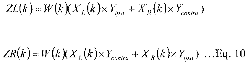
- the desired retention of directional information can be achieved by retaining partial independence of the left and right ear signals to produce a stereophonic output:
- ZL k W k X L k ⁇ Y ipsi + X R k ⁇ Y contra
- ZR k W k X L k ⁇ Y contra + X R k ⁇ Y ipsi
- W max is used in the preferred embodiment to determine additional attenuation to be applied to frequency channels below a few hundred Herz, for which the head is an ineffective barrier. In addition it is used to adjust a slow varying AGC that minimises target level reduction that otherwise increases as noise levels increase relative to the target.
- Alternative metrics to W roax such as the power-weighted average of the attenuation applied to the frequency channels in the 500-4000Hz speech range, may be used in a similar manner.
- the desired target direction can be altered by filtering the left and right ear inputs prior to application of the noise reduction.
- the power of the microphone signals was determined and then a degree of attenuation in the form of filter weights was calculated based on the power values.
- the magnitude of the signals may be determined.
- the degree of attenuation may be calculated based on the magnitude values. In other embodiments, the degree of attenuation may be calculated based on values derived from the magnitude or power values.
- FIG 2 a schematic representation of a modified weight calculation system 200 according the invention is shown.
- the outputs from detection means in the form of the left 201 and right 202 microphones are again transformed into multichannel signals using an analysis filter bank block, 203 and 204, for example using a Fourier Transform to produce left and right signals X L (k) and X R (k) respectively.
- V DIF dependence for low frequencies in system 200 eliminates the need for the additional attenuation factor described in system 100 for very low frequencies.
- the output weights W[k] determined in system 200 can be used to scale the left and right signals X L (k) and X R (k) in the same manner as described for system 100.
- the boundary between high and low frequencies is dependent upon the particular application.
- the boundary between high and low frequencies may vary in the range between 500Hz and 2500Hz. In the detailed embodiment described above, a value of 1000Hz may be used.
Landscapes
- Engineering & Computer Science (AREA)
- Signal Processing (AREA)
- Physics & Mathematics (AREA)
- Acoustics & Sound (AREA)
- Health & Medical Sciences (AREA)
- Computational Linguistics (AREA)
- Quality & Reliability (AREA)
- Audiology, Speech & Language Pathology (AREA)
- Human Computer Interaction (AREA)
- Multimedia (AREA)
- Otolaryngology (AREA)
- General Health & Medical Sciences (AREA)
- Neurosurgery (AREA)
- Circuit For Audible Band Transducer (AREA)
Description
- The present invention relates to a noise reduction method and to systems configured to carry out the method. Embodiments of the invention represent improvements upon, or alternatives to, methods or systems described in applicant's international patent application no
PCT/AU2011/001476 WO2012/065217 . - In hearing devices, such as hearing aids, background noise is detrimental to the intelligibility of speech sounds. Most modern hearing devices address this issue by introducing noise reduction processing technology into the microphone output signal paths. The aim is to increase the Signal-to-Noise (SNR) ratio available to listeners, hence improve clarity and ease of listening to the hearing device wearer.
- The success of noise reduction processing often depends greatly on the formation of appropriate reference signals to estimate the noise, the reason being that the reference signal is used to optimize an adaptive filter that aims to eliminate the noise, ideally leaving only the target signal. However, such reference estimates are often inaccurate because most known techniques, such as Voice Activity Detection, are susceptible to errors. In turn, such inaccuracies lead to inappropriate filtering and degradation in the output quality of processed sound (target distortion), particularly at low SNR where noise reduction functions are most needed.
- There remains a need for improved noise reduction methods and systems.
-
US2012/0207325 discloses a system for suppressing noise in first and second channels that includes obtaining a magnitude difference of signals in the channels, obtaining a magnitude sum of signals in the channels, obtaining a ratio of the magnitude difference to the magnitude sum, generating an attenuation value based on the ratio, selecting an attenuator based on the magnitude difference, and attenuating a signal in a channel by the attenuation value using the selected attenuator. - In a first aspect the present invention refers to a noise reduction method for reducing unwanted sounds in signals received from an arrangement of microphones according to claim 1.
- Further embodiments of the claimed method are defined in the dependent claims 2-13.
- In a second aspect the present invention provides a system for reducing unwanted sounds in signals received from an arrangement of microphones according to claim 14. Further embodiments are defined by dependent claims 15-18.
- In some embodiments, this signal processing technique reduces interference levels in spatially distributed sensor arrays, such as the microphone outputs available in bilateral hearing aids, when the desired target signal arrives from a different direction to those of interfering noise sources. In the field of hearing, this technique can be applied to reduce the effect of noise in devices such as hearing aids, hearing protectors and cochlear implants.
- Embodiments of the invention provide an improved and efficient scheme for the removal of noise present in microphone output signals without the need for complex and error-prone estimates of reference signals.
- Some embodiments may be used in an acoustic system with at least one microphone located at each side of the head producing microphone output signals, a signal processing path to produce an output signal, and means to present this output signal to the auditory system.
- Embodiments of the present invention will now be described, by way of examples only, with reference to the accompanying drawings, in which:
Figure 1 is a block diagram of a system for conducting a noise reduction method for reducing unwanted sounds in signals received from an arrangement of microphones.Figure 2 is a block diagram of a modification of the weight calculation method described inFigure 1 , such that low frequency noise attenuation is improved. - The following description of an embodiment is presented for microphone output signals from the left and right sides of the head. The desired sound source to be attended to is presumed to arrive from a specific direction, referred to as the target direction. In the preferred embodiments, multiband frequency analysis is employed, using for example a Fourier Transform, with left and right channel signals XL (k) and XR (k), respectively, where k denotes the kth frequency channel.
- Referring to
figure 1 , a schematic representation of asystem 100 as part of the invention is shown. Thesystem 100 is embodied in digital signal processing (DSP) hardware and is represented as functional blocks. An overview of the operation of the blocks ofsystem 100 will now be given, and a more detailed explanation of the calculations taking place will follow. - The outputs from detection means in the form of the left 101 and right 102 microphones are transformed into multichannel signals using an analysis filter bank block, 103 and 104, for example using a Fourier Transform to produce left and right signals XL(k) and XR(k) respectively.
- The method then proceeds in the following manner:
- 1. Measure left and right microphone powers (in each frequency band). Power for each channel in the left and right signals are independently determined by way of determination means 105 and 106.
- 2. Calculate PDIF, the difference of microphone powers (assumed to contain the difference between L and R ear noise, and little target because that cancels). The absolute value of PDIF is calculated at 107. That is to say, PDIF always has a positive value.
- 3. Calculate PSUM, the sum of powers (which contains 2xtarget and L and R noise components).
- 4. Time average PDIF and PSUM (optionally with asymmetric rise fall times) by accumulating these values over time using integration processes, 108 and 110, respectively.
- 5. Calculate "attenuation" u(k) at 111 which equates to 1-(PDIF/PSUM), which is an estimate of how much the microphone power needs to be scaled back to better approximate the target-only component. Optionally the ratio (PDIF/PSUM) may by modified by a scaling function prior to subtracting it from one.
- 6. Alter the strength of noise reduction by applying a mapping function that translates "attenuation" to arrive at a set of filter weights W(k) In the preferred embodiment the mapping function takes the form of raising "attenuation" to a fixed power, with a default value of 2.6. The value of the fixed power coefficient may be application dependent, user selectable.
- 7. For low frequencies, there remains the problem that the head provides little attenuation between ears, which leaves much of the noise in that region. To address that problem the very low frequencies are scaled down by an additional factor that is determined from other frequency regions such as a power-weighted average, or alternatively the maximum, of the attenuation applied to the frequencies in the 500-4000Hz range).
- At 112 the left and right signals XL(k) and XR(k) are added together. The filter weights W(k) are applied to the combined signal from
block 111 byprogrammable filter 113 to yield output signal Z(k). - A broadband time-domain signal is optionally created using a synthesis filter bank, 120, for example using an inverse Fourier Transform, and may benefit from further processing such as adjustment of spectral content or time-domain smoothing depending on the application, as will be evident to those skilled in the art.
- In the method described above the left and right signals are added together to produce a monaural signal before the channel weight is applied. This provides an additional SNR gain at the expense of the loss of left and right directional cues. An alternative would be to apply the weight to left and right signals separately to retain directional information. Intermediate to those options, in an alternative implementation, ipsilateral and contralateral signals may be weighted unequally before addition to achieve the desired trade off of additive SNR gain and directional cue retention. Such additive weighting may be fixed, or dynamically determined, for example from the channel attenuation.
- The following formulae are applied in the method conducted by
system 100. - The power in each channel for signals from microphones located on the left and right sides of the head is calculated as follows:


- Eq.1 and Eq.2 describe the situation for which the target direction corresponds to the direction in which the head is orientated. Optionally the target direction can be altered by filtering the left and right microphone signals. Although the target direction can be specified by the user, it should be obvious to those skilled in the art that an automated process can also be used.
- PDIF is calculated as follows:

- PSUM is calculated as follows:

- The time-averaged values of PDIF and PSUM are determined in the preferred embodiment using leaky integration with asymmetric rise (τr) and fall (τf) timesas follows:


- Alternative time-averaging methods can be used.
- The level of attenuation is calculated as follows:

- Optionally, the ratio (
P DIFF /P SUM ) is raised to a power prior to subtraction from 1 to modify the shape of the attenuation function. Because u(k) is always less than or equal to 1, attenuation can be increased by raising its value to a power S:
- Alternative methods to produce the desired strength of noise reduction w(k) from the ratio of (
P DIFF /P SUM ) may be used. It will be evident to those skilled in the art that there may be benefit from adjusting the noise-reduction strength modifier in a time varying manner, for example according to the output of a signal to noise ratio estimator or algorithms that determine the type of acoustic environment automatically. - The channel weighting values W(k) are applied to the combined channel signals XL (k) and XR (k), to produce the channel output signal:

- Further noise reduction and improved quality of the output signal is derived from an estimator of how much noise is being removed in the frequencies most important to voiced speech intelligibility between 500Hz and 4kHz. In the preferred embodiment that estimator is calculated as the largest of the attenuation values applied in the 500-4000Hz speech range:

- Wmax is used in the preferred embodiment to determine additional attenuation to be applied to frequency channels below a few hundred Herz, for which the head is an ineffective barrier. In addition it is used to adjust a slow varying AGC that minimises target level reduction that otherwise increases as noise levels increase relative to the target. Alternative metrics to Wroax, such as the power-weighted average of the attenuation applied to the frequency channels in the 500-4000Hz speech range, may be used in a similar manner.
- It will be evident to those skilled in the art that although the example implementation is described in terms of a target direction that is normal to the microphone configuration, i.e.in the "look direction" of a listener wearing a microphone at each ear, the desired target direction can be altered by filtering the left and right ear inputs prior to application of the noise reduction.
- In the embodiment described above the power of the microphone signals was determined and then a degree of attenuation in the form of filter weights was calculated based on the power values. Similarly, in other embodiments the magnitude of the signals may be determined. The degree of attenuation may be calculated based on the magnitude values. In other embodiments, the degree of attenuation may be calculated based on values derived from the magnitude or power values.
- In a variation to the embodiment described above there may be provided an option to make the attenuation also dependent on phase, rather than amplitude (powers or magnitude) alone. In practice, this new option is used only in low frequency regions where power/magnitude differences between ears can be too small to be effective. In low frequency bands using the new approach, not only are the powers of the left and right signals required, but also the left and right signals need to be subtracted, and the power of their difference (as opposed to the difference of the powers) needs to be calculated.
- Referring to
figure 2 , a schematic representation of a modifiedweight calculation system 200 according the invention is shown. The outputs from detection means in the form of the left 201 and right 202 microphones are again transformed into multichannel signals using an analysis filter bank block, 203 and 204, for example using a Fourier Transform to produce left and right signals XL(k) and XR(k) respectively. - The method then proceeds in the following manner:
- 1. As described in steps 1-3 for
System 100, calculate the values of PSUM, and PDIF from the left and right power values determined by way of power determination means 205 and 206, and absolute value determination means 207. - 2. Subtract the left and right signals, XL(k) and XR(k), and calculate VDIF, the power of the complex vector difference using determination means 208.
- 3. Calculate the preliminary attenuation a(k) values at 209 using PDIF, PSUM, and optionally VDIF. In the preferred embodiment high frequency bands are processed only using PDIF and PSUM according to: a(k) = 1-(PDIF/PSUM), and attenuation for low frequency bands incorporates an additional factor dependent on VDIF according to:

- 4. Optionally alter the strength of the preliminary attenuation to produce the attenuation by applying a mapping function. The mapping function need be neither linear nor time-invariant. In the preferred embodiment, the mapping function is a frequency dependent threshold function that inhibits attenuation above threshold.
- 5. Time average the attenuation by accumulating its values over time using
integration process 208. - 6. Optionally alter the strength of the time-averaged attenuation using a further mapping function to produce attenuation values u[k] using for example a power function with a fixed coefficient. The value of the fixed power coefficient is application dependent, and may be user selectable. In the preferred embodiment, the mapping function is unity for low frequency bands that incorporate VDIF dependence, and equal to 2 otherwise.
- The introduction of VDIF dependence for low frequencies in
system 200 eliminates the need for the additional attenuation factor described insystem 100 for very low frequencies. The output weights W[k] determined insystem 200 can be used to scale the left and right signals XL(k) and XR(k) in the same manner as described forsystem 100. - The following formulae are applied in the method conducted by system 200:
- PL(k) is calculated according to Eq.1
- PR(k) is calculated according to Eq.2
- PDIF is calculated according to Eq. 3.
- PSUM is calculated according to Eq. 4.
- It will be clear to those skilled in the art that alternative measures that exhibit phase-dependence between left and right signals may be used instead of VDIF to enhance performance in the low frequency bands.
- In various embodiments, the boundary between high and low frequencies is dependent upon the particular application. The boundary between high and low frequencies may vary in the range between 500Hz and 2500Hz. In the detailed embodiment described above, a value of 1000Hz may be used.
- Any reference to prior art contained herein is not to be taken as an admission that the information is common general knowledge, unless otherwise indicated.


For low frequency bands, the preliminary attenuation is determined according to:

The time-averaged value of a[k] is determined in the preferred embodiment using frequency-dependent leaky integration as follows:

The time-averaged level of attenuation in the preferred embodiment described in

Claims (18)
- A noise reduction method for reducing unwanted sounds in signals (XL (k), XR (k)) received from an arrangement of microphones (101, 102) including the steps of:sensing sound sources distributed around a specified target direction by way of an arrangement of microphones to produce left and right microphone output signals;determining the magnitude or power of the left and right microphone signals; attenuating the signals based on the difference of the magnitudes or powers or values derived from the magnitudes or powers of the left and right microphone signals; and characterised in that:
the step of attenuating the signals further includes determining the attenuation of selected frequencies based on the magnitude or power of the difference between the left and right microphone signals or a value derived from the magnitude or power of the difference between the left and right microphone signals. - A method according to claim 1 further including the steps of:determining the sum of the magnitudes or powers or values derived from the magnitudes or powers of the left and right microphone signals,wherein the step of attenuating the signals is further based on a comparison of the difference of the magnitudes or powers or values derived from the magnitudes or powers of the left and right microphone signals with the sum of the magnitudes or powers or values derived from the magnitudes or powers of the left and right microphone signals.
- A method according to either of claim 1 or claim 2 wherein the step of attenuating the signal is based on the ratio of the difference of the magnitudes or powers or values derived from the magnitudes or powers of the left and right microphone signals to the sum of the magnitudes or powers or values derived from the magnitudes or powers of the left and right microphone signals.
- A method according to claim 3 wherein the step of attenuating is based on one minus the ratio, on a transformation of the ratio, or on one minus the transformation of the ratio.
- A method according to claim 1 wherein the difference of the magnitudes or powers or values derived from the magnitudes or powers of the left and right microphone signals is time-averaged.
- A method according to claim 2 wherein the sum of the magnitudes or powers or values derived from the magnitudes or powers of the left and right microphone signals is time-averaged.
- A method according to either of claims 5 or 6 wherein the step of time-averaging includes asymmetric rise and fall times
- A method according to any preceding claim wherein the step of attenuating is frequency specific.
- A method according to any preceding claim wherein the step of attenuating includes determining the attenuation of low frequencies from other frequency bands.
- A method according to any preceding claim wherein the attenuation is scaled by a function.
- A method according to any preceding claim wherein any unwanted reduction of target output level in high noise levels is eliminated through an estimator of the amount of noise being eliminated.
- A method according to a claim 11 wherein an estimator of the amount of noise being eliminated over a frequency range of interest is derived from the maximum attenuation applied across that range.
- A method according to any preceding claim wherein the said selected frequencies are low frequencies.
- A system for reducing unwanted sounds in signals (XL (k), XR (k)) received from an arrangement of microphones (101, 102) including:sensing means for sound sources distributed around a specified target direction by way of an arrangement of microphones to produce left and right microphone output signals;determination means (105, 106) for determining the magnitude or power of the left and right microphone signals;attenuation means for attenuating the signals based on the difference of the magnitudes or powers or values derived from the magnitudes or powers of the left and right microphone signals; and characterised in that:
the attenuation means is arranged to attenuate selected frequencies based on the magnitude or power of the difference between the left and right microphone signals or a value derived from the magnitude or power of the difference between the left and right microphone signals. - A system according to claim 14 wherein the determination means is further arranged to determine the sum of the magnitudes or powers or values derived from the magnitudes or powers of the left and right microphone signals; and the attenuation means is further arranged to attenuate the signals based on a comparison of the difference of the magnitudes or powers or values derived from the magnitudes or powers of the left and right microphone signals with the sum of the magnitudes or powers or values derived from the magnitudes or powers of the left and right microphone signals.
- A system according to claim 14 wherein the attenuation means is arranged to attenuate the signals based on the ratio of the difference of the magnitudes or powers or values derived from the magnitudes or powers of the left and right microphone signals to the sum of the magnitudes or powers or values derived from the magnitudes or powers of the left and right microphone signals.
- A system according to claim 16 wherein the attenuation means is arranged to attenuate the signals based on one minus the ratio, on a transformation of the ratio, or on one minus the transformation of the ratio.
- A system according to any one of claims 14 to 17 wherein the said selected frequencies are low frequencies.
Applications Claiming Priority (2)
| Application Number | Priority Date | Filing Date | Title |
|---|---|---|---|
| AU2013900843A AU2013900843A0 (en) | 2013-03-12 | A noise reduction method and system | |
| PCT/AU2014/000178 WO2014138774A1 (en) | 2013-03-12 | 2014-02-26 | A noise reduction method and system |
Publications (3)
| Publication Number | Publication Date |
|---|---|
| EP2974084A1 EP2974084A1 (en) | 2016-01-20 |
| EP2974084A4 EP2974084A4 (en) | 2016-11-09 |
| EP2974084B1 true EP2974084B1 (en) | 2020-08-05 |
Family
ID=51535592
Family Applications (1)
| Application Number | Title | Priority Date | Filing Date |
|---|---|---|---|
| EP14764221.9A Revoked EP2974084B1 (en) | 2013-03-12 | 2014-02-26 | A noise reduction method and system |
Country Status (7)
| Country | Link |
|---|---|
| US (1) | US10347269B2 (en) |
| EP (1) | EP2974084B1 (en) |
| JP (1) | JP2016515342A (en) |
| CN (1) | CN105051814A (en) |
| AU (4) | AU2014231751A1 (en) |
| DK (1) | DK2974084T3 (en) |
| WO (1) | WO2014138774A1 (en) |
Families Citing this family (8)
| Publication number | Priority date | Publication date | Assignee | Title |
|---|---|---|---|---|
| US11852741B2 (en) * | 2014-09-29 | 2023-12-26 | Telecom Italia S.P.A. | Positioning method and system for wireless communication networks |
| WO2016131064A1 (en) | 2015-02-13 | 2016-08-18 | Noopl, Inc. | System and method for improving hearing |
| US20180067212A1 (en) * | 2016-09-02 | 2018-03-08 | Apple Inc. | Infrared-Transparent Window Coatings for Electronic Device Sensors |
| KR102669375B1 (en) * | 2018-05-18 | 2024-05-29 | 젠텍스코오포레이션 | Headset Communication System |
| TWI674005B (en) * | 2018-06-27 | 2019-10-01 | 塞席爾商元鼎音訊股份有限公司 | Binaural hearing aid and method of reducing a noise generated via touching a hearing aid |
| US11451919B2 (en) * | 2021-02-19 | 2022-09-20 | Boomcloud 360, Inc. | All-pass network system for colorless decorrelation with constraints |
| KR20250052461A (en) | 2021-07-08 | 2025-04-18 | 붐클라우드 360 인코포레이티드 | Colorless generation of elevation perceptual cues using all-pass filter networks |
| EP4125276A3 (en) | 2021-07-30 | 2023-04-19 | Starkey Laboratories, Inc. | Spatially differentiated noise reduction for hearing devices |
Citations (40)
| Publication number | Priority date | Publication date | Assignee | Title |
|---|---|---|---|---|
| US4456795A (en) | 1981-02-13 | 1984-06-26 | Rion Kabushiki Kaisha | Behind-the-ear type hearing aid |
| US4683449A (en) | 1984-05-02 | 1987-07-28 | Pioneer Electronic Corporation | Noise reduction compression system controlled by compressed output components which are in-band |
| US5550925A (en) | 1991-01-07 | 1996-08-27 | Canon Kabushiki Kaisha | Sound processing device |
| WO1999033324A1 (en) | 1997-12-22 | 1999-07-01 | Audio-Technica, U.S., Inc. | Digital and analog directional microphone |
| JP2000261894A (en) | 1999-03-04 | 2000-09-22 | Matsushita Electric Ind Co Ltd | Hearing aid with noise suppression |
| WO2001052242A1 (en) | 2000-01-12 | 2001-07-19 | Sonic Innovations, Inc. | Noise reduction apparatus and method |
| WO2001069968A2 (en) | 2000-03-14 | 2001-09-20 | Audia Technology, Inc. | Adaptive microphone matching in multi-microphone directional system |
| US20010028718A1 (en) | 2000-02-17 | 2001-10-11 | Audia Technology, Inc. | Null adaptation in multi-microphone directional system |
| US20030147538A1 (en) | 2002-02-05 | 2003-08-07 | Mh Acoustics, Llc, A Delaware Corporation | Reducing noise in audio systems |
| US20050129258A1 (en) | 2001-02-09 | 2005-06-16 | Fincham Lawrence R. | Narrow profile speaker configurations and systems |
| US6983055B2 (en) | 2000-06-13 | 2006-01-03 | Gn Resound North America Corporation | Method and apparatus for an adaptive binaural beamforming system |
| US20060233391A1 (en) | 2005-04-19 | 2006-10-19 | Park Jae-Ha | Audio data processing apparatus and method to reduce wind noise |
| US20070021958A1 (en) | 2005-07-22 | 2007-01-25 | Erik Visser | Robust separation of speech signals in a noisy environment |
| US20080019548A1 (en) | 2006-01-30 | 2008-01-24 | Audience, Inc. | System and method for utilizing omni-directional microphones for speech enhancement |
| WO2008079327A1 (en) | 2006-12-22 | 2008-07-03 | Step Labs, Inc. | Near-field vector signal enhancement |
| US20080212794A1 (en) | 2007-03-01 | 2008-09-04 | Canon Kabushiki Kaisha | Audio processing apparatus |
| US20080260175A1 (en) | 2002-02-05 | 2008-10-23 | Mh Acoustics, Llc | Dual-Microphone Spatial Noise Suppression |
| US20090052688A1 (en) | 2005-11-15 | 2009-02-26 | Yamaha Corporation | Remote conference apparatus and sound emitting/collecting apparatus |
| EP2056296A2 (en) | 2007-10-24 | 2009-05-06 | QNX Software Systems (Wavemakers), Inc. | Dynamic noise reduction |
| US20090175466A1 (en) | 2002-02-05 | 2009-07-09 | Mh Acoustics, Llc | Noise-reducing directional microphone array |
| US20090226006A1 (en) | 2007-10-19 | 2009-09-10 | Sennheiser Electronic Corporation | Microphone device |
| US20090292536A1 (en) | 2007-10-24 | 2009-11-26 | Hetherington Phillip A | Speech enhancement with minimum gating |
| EP2175446A2 (en) | 2008-10-10 | 2010-04-14 | Samsung Electronics Co., Ltd. | Apparatus and method for noise estimation, and noise reduction apparatus employing the same |
| US20100232616A1 (en) | 2009-03-13 | 2010-09-16 | Harris Corporation | Noise error amplitude reduction |
| EP2234415A1 (en) | 2009-03-24 | 2010-09-29 | Siemens Medical Instruments Pte. Ltd. | Method and acoustic signal processing system for binaural noise reduction |
| US7822217B2 (en) | 2002-05-15 | 2010-10-26 | Micro Ear Technology, Inc. | Hearing assistance systems for providing second-order gradient directional signals |
| JP2011048302A (en) | 2009-08-28 | 2011-03-10 | Fujitsu Ltd | Noise reduction device and noise reduction program |
| EP2360943A1 (en) | 2009-12-29 | 2011-08-24 | GN Resound A/S | Beamforming in hearing aids |
| WO2011101043A1 (en) | 2010-02-19 | 2011-08-25 | Siemens Medical Instruments Pte. Ltd. | Method for the binaural left-right localization for hearing instruments |
| WO2011101045A1 (en) | 2010-02-19 | 2011-08-25 | Siemens Medical Instruments Pte. Ltd. | Device and method for direction dependent spatial noise reduction |
| EP2395506A1 (en) | 2010-06-09 | 2011-12-14 | Siemens Medical Instruments Pte. Ltd. | Method and acoustic signal processing system for interference and noise suppression in binaural microphone configurations |
| US20110317848A1 (en) | 2010-06-23 | 2011-12-29 | Motorola, Inc. | Microphone Interference Detection Method and Apparatus |
| US8135142B2 (en) | 2004-11-02 | 2012-03-13 | Siemens Audiologische Technic Gmbh | Method for reducing interferences of a directional microphone |
| US20120114142A1 (en) | 2009-07-07 | 2012-05-10 | Shuichiro Nishigori | Acoustic signal processing apparatus, processing method therefor, and program |
| WO2012065217A1 (en) | 2010-11-18 | 2012-05-24 | Hear Ip Pty Ltd | Systems and methods for reducing unwanted sounds in signals received from an arrangement of microphones |
| US20120140946A1 (en) | 2010-12-01 | 2012-06-07 | Cambridge Silicon Radio Limited | Wind Noise Mitigation |
| US20120207325A1 (en) | 2011-02-10 | 2012-08-16 | Dolby Laboratories Licensing Corporation | Multi-Channel Wind Noise Suppression System and Method |
| US8290189B2 (en) | 2009-01-21 | 2012-10-16 | Siemens Aktiengesellschaft | Blind source separation method and acoustic signal processing system for improving interference estimation in binaural wiener filtering |
| US8358789B2 (en) | 2008-11-04 | 2013-01-22 | Siemens Medical Instruments Pte. Ltd. | Adaptive microphone system for a hearing device and associated operating method |
| US8774426B2 (en) | 2010-07-16 | 2014-07-08 | Lapis Semiconductor Co., Ltd. | Signal processing apparatus, semiconductor chip, signal processing system, and method of processing signal |
Family Cites Families (5)
| Publication number | Priority date | Publication date | Assignee | Title |
|---|---|---|---|---|
| KR101434071B1 (en) * | 2002-03-27 | 2014-08-26 | 앨리프컴 | Microphone and voice activity detection (vad) configurations for use with communication systems |
| US8068619B2 (en) * | 2006-05-09 | 2011-11-29 | Fortemedia, Inc. | Method and apparatus for noise suppression in a small array microphone system |
| US8411880B2 (en) * | 2008-01-29 | 2013-04-02 | Qualcomm Incorporated | Sound quality by intelligently selecting between signals from a plurality of microphones |
| US8348549B2 (en) * | 2010-07-17 | 2013-01-08 | Stiles Brady A | Method and apparatus for absorptive boom |
| JP5857403B2 (en) * | 2010-12-17 | 2016-02-10 | 富士通株式会社 | Voice processing apparatus and voice processing program |
-
2014
- 2014-02-26 US US14/771,468 patent/US10347269B2/en active Active
- 2014-02-26 JP JP2015561823A patent/JP2016515342A/en active Pending
- 2014-02-26 CN CN201480010905.5A patent/CN105051814A/en active Pending
- 2014-02-26 AU AU2014231751A patent/AU2014231751A1/en not_active Abandoned
- 2014-02-26 WO PCT/AU2014/000178 patent/WO2014138774A1/en not_active Ceased
- 2014-02-26 EP EP14764221.9A patent/EP2974084B1/en not_active Revoked
- 2014-02-26 DK DK14764221.9T patent/DK2974084T3/en active
-
2018
- 2018-04-04 AU AU2018202354A patent/AU2018202354A1/en not_active Abandoned
-
2020
- 2020-06-09 AU AU2020203800A patent/AU2020203800A1/en not_active Abandoned
-
2022
- 2022-07-13 AU AU2022205203A patent/AU2022205203B2/en not_active Expired - Fee Related
Patent Citations (40)
| Publication number | Priority date | Publication date | Assignee | Title |
|---|---|---|---|---|
| US4456795A (en) | 1981-02-13 | 1984-06-26 | Rion Kabushiki Kaisha | Behind-the-ear type hearing aid |
| US4683449A (en) | 1984-05-02 | 1987-07-28 | Pioneer Electronic Corporation | Noise reduction compression system controlled by compressed output components which are in-band |
| US5550925A (en) | 1991-01-07 | 1996-08-27 | Canon Kabushiki Kaisha | Sound processing device |
| WO1999033324A1 (en) | 1997-12-22 | 1999-07-01 | Audio-Technica, U.S., Inc. | Digital and analog directional microphone |
| JP2000261894A (en) | 1999-03-04 | 2000-09-22 | Matsushita Electric Ind Co Ltd | Hearing aid with noise suppression |
| WO2001052242A1 (en) | 2000-01-12 | 2001-07-19 | Sonic Innovations, Inc. | Noise reduction apparatus and method |
| US20010028718A1 (en) | 2000-02-17 | 2001-10-11 | Audia Technology, Inc. | Null adaptation in multi-microphone directional system |
| WO2001069968A2 (en) | 2000-03-14 | 2001-09-20 | Audia Technology, Inc. | Adaptive microphone matching in multi-microphone directional system |
| US6983055B2 (en) | 2000-06-13 | 2006-01-03 | Gn Resound North America Corporation | Method and apparatus for an adaptive binaural beamforming system |
| US20050129258A1 (en) | 2001-02-09 | 2005-06-16 | Fincham Lawrence R. | Narrow profile speaker configurations and systems |
| US20080260175A1 (en) | 2002-02-05 | 2008-10-23 | Mh Acoustics, Llc | Dual-Microphone Spatial Noise Suppression |
| US20090175466A1 (en) | 2002-02-05 | 2009-07-09 | Mh Acoustics, Llc | Noise-reducing directional microphone array |
| US20030147538A1 (en) | 2002-02-05 | 2003-08-07 | Mh Acoustics, Llc, A Delaware Corporation | Reducing noise in audio systems |
| US7822217B2 (en) | 2002-05-15 | 2010-10-26 | Micro Ear Technology, Inc. | Hearing assistance systems for providing second-order gradient directional signals |
| US8135142B2 (en) | 2004-11-02 | 2012-03-13 | Siemens Audiologische Technic Gmbh | Method for reducing interferences of a directional microphone |
| US20060233391A1 (en) | 2005-04-19 | 2006-10-19 | Park Jae-Ha | Audio data processing apparatus and method to reduce wind noise |
| US20070021958A1 (en) | 2005-07-22 | 2007-01-25 | Erik Visser | Robust separation of speech signals in a noisy environment |
| US20090052688A1 (en) | 2005-11-15 | 2009-02-26 | Yamaha Corporation | Remote conference apparatus and sound emitting/collecting apparatus |
| US20080019548A1 (en) | 2006-01-30 | 2008-01-24 | Audience, Inc. | System and method for utilizing omni-directional microphones for speech enhancement |
| WO2008079327A1 (en) | 2006-12-22 | 2008-07-03 | Step Labs, Inc. | Near-field vector signal enhancement |
| US20080212794A1 (en) | 2007-03-01 | 2008-09-04 | Canon Kabushiki Kaisha | Audio processing apparatus |
| US20090226006A1 (en) | 2007-10-19 | 2009-09-10 | Sennheiser Electronic Corporation | Microphone device |
| US20090292536A1 (en) | 2007-10-24 | 2009-11-26 | Hetherington Phillip A | Speech enhancement with minimum gating |
| EP2056296A2 (en) | 2007-10-24 | 2009-05-06 | QNX Software Systems (Wavemakers), Inc. | Dynamic noise reduction |
| EP2175446A2 (en) | 2008-10-10 | 2010-04-14 | Samsung Electronics Co., Ltd. | Apparatus and method for noise estimation, and noise reduction apparatus employing the same |
| US8358789B2 (en) | 2008-11-04 | 2013-01-22 | Siemens Medical Instruments Pte. Ltd. | Adaptive microphone system for a hearing device and associated operating method |
| US8290189B2 (en) | 2009-01-21 | 2012-10-16 | Siemens Aktiengesellschaft | Blind source separation method and acoustic signal processing system for improving interference estimation in binaural wiener filtering |
| US20100232616A1 (en) | 2009-03-13 | 2010-09-16 | Harris Corporation | Noise error amplitude reduction |
| EP2234415A1 (en) | 2009-03-24 | 2010-09-29 | Siemens Medical Instruments Pte. Ltd. | Method and acoustic signal processing system for binaural noise reduction |
| US20120114142A1 (en) | 2009-07-07 | 2012-05-10 | Shuichiro Nishigori | Acoustic signal processing apparatus, processing method therefor, and program |
| JP2011048302A (en) | 2009-08-28 | 2011-03-10 | Fujitsu Ltd | Noise reduction device and noise reduction program |
| EP2360943A1 (en) | 2009-12-29 | 2011-08-24 | GN Resound A/S | Beamforming in hearing aids |
| WO2011101043A1 (en) | 2010-02-19 | 2011-08-25 | Siemens Medical Instruments Pte. Ltd. | Method for the binaural left-right localization for hearing instruments |
| WO2011101045A1 (en) | 2010-02-19 | 2011-08-25 | Siemens Medical Instruments Pte. Ltd. | Device and method for direction dependent spatial noise reduction |
| EP2395506A1 (en) | 2010-06-09 | 2011-12-14 | Siemens Medical Instruments Pte. Ltd. | Method and acoustic signal processing system for interference and noise suppression in binaural microphone configurations |
| US20110317848A1 (en) | 2010-06-23 | 2011-12-29 | Motorola, Inc. | Microphone Interference Detection Method and Apparatus |
| US8774426B2 (en) | 2010-07-16 | 2014-07-08 | Lapis Semiconductor Co., Ltd. | Signal processing apparatus, semiconductor chip, signal processing system, and method of processing signal |
| WO2012065217A1 (en) | 2010-11-18 | 2012-05-24 | Hear Ip Pty Ltd | Systems and methods for reducing unwanted sounds in signals received from an arrangement of microphones |
| US20120140946A1 (en) | 2010-12-01 | 2012-06-07 | Cambridge Silicon Radio Limited | Wind Noise Mitigation |
| US20120207325A1 (en) | 2011-02-10 | 2012-08-16 | Dolby Laboratories Licensing Corporation | Multi-Channel Wind Noise Suppression System and Method |
Also Published As
| Publication number | Publication date |
|---|---|
| EP2974084A4 (en) | 2016-11-09 |
| AU2022205203A1 (en) | 2022-08-04 |
| EP2974084A1 (en) | 2016-01-20 |
| AU2018202354A1 (en) | 2018-04-26 |
| AU2022205203B2 (en) | 2023-12-14 |
| WO2014138774A1 (en) | 2014-09-18 |
| DK2974084T3 (en) | 2020-11-09 |
| CN105051814A (en) | 2015-11-11 |
| US10347269B2 (en) | 2019-07-09 |
| AU2020203800A1 (en) | 2020-07-02 |
| US20160005417A1 (en) | 2016-01-07 |
| AU2014231751A1 (en) | 2015-07-30 |
| JP2016515342A (en) | 2016-05-26 |
Similar Documents
| Publication | Publication Date | Title |
|---|---|---|
| AU2022205203B2 (en) | A noise reduction method and system | |
| EP4115413B1 (en) | Voice optimization in noisy environments | |
| CN107484080B (en) | Audio processing apparatus and method for estimating signal-to-noise ratio of sound signal | |
| EP3040984B1 (en) | Sound zone arrangment with zonewise speech suppresion | |
| JP4732706B2 (en) | Binaural signal enhancement system | |
| US9854368B2 (en) | Method of operating a hearing aid system and a hearing aid system | |
| CN103874002A (en) | Audio processing device comprising reduced artifacts | |
| CN106507258B (en) | Hearing device and operation method thereof | |
| EP2641346B2 (en) | Systems and methods for reducing unwanted sounds in signals received from an arrangement of microphones | |
| EP2930955A1 (en) | Adaptive filtering | |
| US8233650B2 (en) | Multi-stage estimation method for noise reduction and hearing apparatus | |
| US20040258249A1 (en) | Method for operating a hearing aid device and hearing aid device with a microphone system in which different directional characteristics can be set | |
| Xiao et al. | Soft-constrained spatially selective active noise control for open-fitting hearables | |
| US20220223135A1 (en) | Applying noise suppression to remote and local microphone signals | |
| Hersbach et al. | Algorithms to improve listening in noise for cochlear implant users |
Legal Events
| Date | Code | Title | Description |
|---|---|---|---|
| PUAI | Public reference made under article 153(3) epc to a published international application that has entered the european phase |
Free format text: ORIGINAL CODE: 0009012 |
|
| 17P | Request for examination filed |
Effective date: 20150828 |
|
| AK | Designated contracting states |
Kind code of ref document: A1 Designated state(s): AL AT BE BG CH CY CZ DE DK EE ES FI FR GB GR HR HU IE IS IT LI LT LU LV MC MK MT NL NO PL PT RO RS SE SI SK SM TR |
|
| AX | Request for extension of the european patent |
Extension state: BA ME |
|
| DAX | Request for extension of the european patent (deleted) | ||
| A4 | Supplementary search report drawn up and despatched |
Effective date: 20161012 |
|
| RIC1 | Information provided on ipc code assigned before grant |
Ipc: H04R 3/00 20060101AFI20161006BHEP Ipc: G10L 21/0216 20130101ALN20161006BHEP Ipc: G10L 21/0232 20130101ALI20161006BHEP Ipc: H04R 25/00 20060101ALI20161006BHEP Ipc: G10L 21/0208 20130101ALI20161006BHEP |
|
| REG | Reference to a national code |
Ref country code: DE Ref legal event code: R079 Ref document number: 602014068599 Country of ref document: DE Free format text: PREVIOUS MAIN CLASS: H04B0015000000 Ipc: H04R0003000000 |
|
| GRAP | Despatch of communication of intention to grant a patent |
Free format text: ORIGINAL CODE: EPIDOSNIGR1 |
|
| STAA | Information on the status of an ep patent application or granted ep patent |
Free format text: STATUS: GRANT OF PATENT IS INTENDED |
|
| RIC1 | Information provided on ipc code assigned before grant |
Ipc: G10L 21/0216 20130101ALN20191018BHEP Ipc: H04R 3/00 20060101AFI20191018BHEP Ipc: H04R 25/00 20060101ALI20191018BHEP Ipc: G10L 21/0208 20130101ALI20191018BHEP Ipc: G10L 21/0232 20130101ALI20191018BHEP |
|
| RIC1 | Information provided on ipc code assigned before grant |
Ipc: G10L 21/0208 20130101ALI20191113BHEP Ipc: H04R 3/00 20060101AFI20191113BHEP Ipc: H04R 25/00 20060101ALI20191113BHEP Ipc: G10L 21/0216 20130101ALN20191113BHEP Ipc: G10L 21/0232 20130101ALI20191113BHEP |
|
| INTG | Intention to grant announced |
Effective date: 20191127 |
|
| GRAS | Grant fee paid |
Free format text: ORIGINAL CODE: EPIDOSNIGR3 |
|
| GRAA | (expected) grant |
Free format text: ORIGINAL CODE: 0009210 |
|
| STAA | Information on the status of an ep patent application or granted ep patent |
Free format text: STATUS: THE PATENT HAS BEEN GRANTED |
|
| AK | Designated contracting states |
Kind code of ref document: B1 Designated state(s): AL AT BE BG CH CY CZ DE DK EE ES FI FR GB GR HR HU IE IS IT LI LT LU LV MC MK MT NL NO PL PT RO RS SE SI SK SM TR |
|
| REG | Reference to a national code |
Ref country code: GB Ref legal event code: FG4D |
|
| REG | Reference to a national code |
Ref country code: CH Ref legal event code: EP |
|
| REG | Reference to a national code |
Ref country code: AT Ref legal event code: REF Ref document number: 1300413 Country of ref document: AT Kind code of ref document: T Effective date: 20200815 |
|
| REG | Reference to a national code |
Ref country code: DE Ref legal event code: R096 Ref document number: 602014068599 Country of ref document: DE |
|
| REG | Reference to a national code |
Ref country code: IE Ref legal event code: FG4D |
|
| REG | Reference to a national code |
Ref country code: DK Ref legal event code: T3 Effective date: 20201106 |
|
| REG | Reference to a national code |
Ref country code: LT Ref legal event code: MG4D |
|
| REG | Reference to a national code |
Ref country code: NL Ref legal event code: MP Effective date: 20200805 |
|
| REG | Reference to a national code |
Ref country code: AT Ref legal event code: MK05 Ref document number: 1300413 Country of ref document: AT Kind code of ref document: T Effective date: 20200805 |
|
| PG25 | Lapsed in a contracting state [announced via postgrant information from national office to epo] |
Ref country code: FI Free format text: LAPSE BECAUSE OF FAILURE TO SUBMIT A TRANSLATION OF THE DESCRIPTION OR TO PAY THE FEE WITHIN THE PRESCRIBED TIME-LIMIT Effective date: 20200805 Ref country code: ES Free format text: LAPSE BECAUSE OF FAILURE TO SUBMIT A TRANSLATION OF THE DESCRIPTION OR TO PAY THE FEE WITHIN THE PRESCRIBED TIME-LIMIT Effective date: 20200805 Ref country code: LT Free format text: LAPSE BECAUSE OF FAILURE TO SUBMIT A TRANSLATION OF THE DESCRIPTION OR TO PAY THE FEE WITHIN THE PRESCRIBED TIME-LIMIT Effective date: 20200805 Ref country code: PT Free format text: LAPSE BECAUSE OF FAILURE TO SUBMIT A TRANSLATION OF THE DESCRIPTION OR TO PAY THE FEE WITHIN THE PRESCRIBED TIME-LIMIT Effective date: 20201207 Ref country code: AT Free format text: LAPSE BECAUSE OF FAILURE TO SUBMIT A TRANSLATION OF THE DESCRIPTION OR TO PAY THE FEE WITHIN THE PRESCRIBED TIME-LIMIT Effective date: 20200805 Ref country code: NO Free format text: LAPSE BECAUSE OF FAILURE TO SUBMIT A TRANSLATION OF THE DESCRIPTION OR TO PAY THE FEE WITHIN THE PRESCRIBED TIME-LIMIT Effective date: 20201105 Ref country code: HR Free format text: LAPSE BECAUSE OF FAILURE TO SUBMIT A TRANSLATION OF THE DESCRIPTION OR TO PAY THE FEE WITHIN THE PRESCRIBED TIME-LIMIT Effective date: 20200805 Ref country code: GR Free format text: LAPSE BECAUSE OF FAILURE TO SUBMIT A TRANSLATION OF THE DESCRIPTION OR TO PAY THE FEE WITHIN THE PRESCRIBED TIME-LIMIT Effective date: 20201106 Ref country code: SE Free format text: LAPSE BECAUSE OF FAILURE TO SUBMIT A TRANSLATION OF THE DESCRIPTION OR TO PAY THE FEE WITHIN THE PRESCRIBED TIME-LIMIT Effective date: 20200805 Ref country code: BG Free format text: LAPSE BECAUSE OF FAILURE TO SUBMIT A TRANSLATION OF THE DESCRIPTION OR TO PAY THE FEE WITHIN THE PRESCRIBED TIME-LIMIT Effective date: 20201105 |
|
| PG25 | Lapsed in a contracting state [announced via postgrant information from national office to epo] |
Ref country code: IS Free format text: LAPSE BECAUSE OF FAILURE TO SUBMIT A TRANSLATION OF THE DESCRIPTION OR TO PAY THE FEE WITHIN THE PRESCRIBED TIME-LIMIT Effective date: 20201205 Ref country code: PL Free format text: LAPSE BECAUSE OF FAILURE TO SUBMIT A TRANSLATION OF THE DESCRIPTION OR TO PAY THE FEE WITHIN THE PRESCRIBED TIME-LIMIT Effective date: 20200805 Ref country code: NL Free format text: LAPSE BECAUSE OF FAILURE TO SUBMIT A TRANSLATION OF THE DESCRIPTION OR TO PAY THE FEE WITHIN THE PRESCRIBED TIME-LIMIT Effective date: 20200805 Ref country code: RS Free format text: LAPSE BECAUSE OF FAILURE TO SUBMIT A TRANSLATION OF THE DESCRIPTION OR TO PAY THE FEE WITHIN THE PRESCRIBED TIME-LIMIT Effective date: 20200805 Ref country code: LV Free format text: LAPSE BECAUSE OF FAILURE TO SUBMIT A TRANSLATION OF THE DESCRIPTION OR TO PAY THE FEE WITHIN THE PRESCRIBED TIME-LIMIT Effective date: 20200805 |
|
| PG25 | Lapsed in a contracting state [announced via postgrant information from national office to epo] |
Ref country code: RO Free format text: LAPSE BECAUSE OF FAILURE TO SUBMIT A TRANSLATION OF THE DESCRIPTION OR TO PAY THE FEE WITHIN THE PRESCRIBED TIME-LIMIT Effective date: 20200805 Ref country code: SM Free format text: LAPSE BECAUSE OF FAILURE TO SUBMIT A TRANSLATION OF THE DESCRIPTION OR TO PAY THE FEE WITHIN THE PRESCRIBED TIME-LIMIT Effective date: 20200805 Ref country code: CZ Free format text: LAPSE BECAUSE OF FAILURE TO SUBMIT A TRANSLATION OF THE DESCRIPTION OR TO PAY THE FEE WITHIN THE PRESCRIBED TIME-LIMIT Effective date: 20200805 Ref country code: EE Free format text: LAPSE BECAUSE OF FAILURE TO SUBMIT A TRANSLATION OF THE DESCRIPTION OR TO PAY THE FEE WITHIN THE PRESCRIBED TIME-LIMIT Effective date: 20200805 |
|
| REG | Reference to a national code |
Ref country code: DE Ref legal event code: R026 Ref document number: 602014068599 Country of ref document: DE |
|
| PLBI | Opposition filed |
Free format text: ORIGINAL CODE: 0009260 |
|
| PLAX | Notice of opposition and request to file observation + time limit sent |
Free format text: ORIGINAL CODE: EPIDOSNOBS2 |
|
| PG25 | Lapsed in a contracting state [announced via postgrant information from national office to epo] |
Ref country code: AL Free format text: LAPSE BECAUSE OF FAILURE TO SUBMIT A TRANSLATION OF THE DESCRIPTION OR TO PAY THE FEE WITHIN THE PRESCRIBED TIME-LIMIT Effective date: 20200805 |
|
| 26 | Opposition filed |
Opponent name: K/S HIMPP Effective date: 20210505 |
|
| PG25 | Lapsed in a contracting state [announced via postgrant information from national office to epo] |
Ref country code: SK Free format text: LAPSE BECAUSE OF FAILURE TO SUBMIT A TRANSLATION OF THE DESCRIPTION OR TO PAY THE FEE WITHIN THE PRESCRIBED TIME-LIMIT Effective date: 20200805 |
|
| PG25 | Lapsed in a contracting state [announced via postgrant information from national office to epo] |
Ref country code: IT Free format text: LAPSE BECAUSE OF FAILURE TO SUBMIT A TRANSLATION OF THE DESCRIPTION OR TO PAY THE FEE WITHIN THE PRESCRIBED TIME-LIMIT Effective date: 20200805 |
|
| PG25 | Lapsed in a contracting state [announced via postgrant information from national office to epo] |
Ref country code: SI Free format text: LAPSE BECAUSE OF FAILURE TO SUBMIT A TRANSLATION OF THE DESCRIPTION OR TO PAY THE FEE WITHIN THE PRESCRIBED TIME-LIMIT Effective date: 20200805 |
|
| PG25 | Lapsed in a contracting state [announced via postgrant information from national office to epo] |
Ref country code: MC Free format text: LAPSE BECAUSE OF FAILURE TO SUBMIT A TRANSLATION OF THE DESCRIPTION OR TO PAY THE FEE WITHIN THE PRESCRIBED TIME-LIMIT Effective date: 20200805 |
|
| PLBB | Reply of patent proprietor to notice(s) of opposition received |
Free format text: ORIGINAL CODE: EPIDOSNOBS3 |
|
| PG25 | Lapsed in a contracting state [announced via postgrant information from national office to epo] |
Ref country code: LU Free format text: LAPSE BECAUSE OF NON-PAYMENT OF DUE FEES Effective date: 20210226 |
|
| RAP2 | Party data changed (patent owner data changed or rights of a patent transferred) |
Owner name: NOOPL, INC. |
|
| PLCK | Communication despatched that opposition was rejected |
Free format text: ORIGINAL CODE: EPIDOSNREJ1 |
|
| REG | Reference to a national code |
Ref country code: GB Ref legal event code: 732E Free format text: REGISTERED BETWEEN 20230126 AND 20230201 |
|
| PLAB | Opposition data, opponent's data or that of the opponent's representative modified |
Free format text: ORIGINAL CODE: 0009299OPPO |
|
| APBM | Appeal reference recorded |
Free format text: ORIGINAL CODE: EPIDOSNREFNO |
|
| APBP | Date of receipt of notice of appeal recorded |
Free format text: ORIGINAL CODE: EPIDOSNNOA2O |
|
| R26 | Opposition filed (corrected) |
Opponent name: K/S HIMPP Effective date: 20210505 |
|
| APAH | Appeal reference modified |
Free format text: ORIGINAL CODE: EPIDOSCREFNO |
|
| PGFP | Annual fee paid to national office [announced via postgrant information from national office to epo] |
Ref country code: IE Payment date: 20230109 Year of fee payment: 10 Ref country code: FR Payment date: 20230109 Year of fee payment: 10 Ref country code: DK Payment date: 20230109 Year of fee payment: 10 Ref country code: CH Payment date: 20230307 Year of fee payment: 10 |
|
| PG25 | Lapsed in a contracting state [announced via postgrant information from national office to epo] |
Ref country code: HU Free format text: LAPSE BECAUSE OF FAILURE TO SUBMIT A TRANSLATION OF THE DESCRIPTION OR TO PAY THE FEE WITHIN THE PRESCRIBED TIME-LIMIT; INVALID AB INITIO Effective date: 20140226 |
|
| PGFP | Annual fee paid to national office [announced via postgrant information from national office to epo] |
Ref country code: GB Payment date: 20230109 Year of fee payment: 10 Ref country code: DE Payment date: 20230112 Year of fee payment: 10 Ref country code: BE Payment date: 20230111 Year of fee payment: 10 |
|
| APBQ | Date of receipt of statement of grounds of appeal recorded |
Free format text: ORIGINAL CODE: EPIDOSNNOA3O |
|
| P01 | Opt-out of the competence of the unified patent court (upc) registered |
Effective date: 20230522 |
|
| PG25 | Lapsed in a contracting state [announced via postgrant information from national office to epo] |
Ref country code: CY Free format text: LAPSE BECAUSE OF FAILURE TO SUBMIT A TRANSLATION OF THE DESCRIPTION OR TO PAY THE FEE WITHIN THE PRESCRIBED TIME-LIMIT Effective date: 20200805 |
|
| APAH | Appeal reference modified |
Free format text: ORIGINAL CODE: EPIDOSCREFNO |
|
| PG25 | Lapsed in a contracting state [announced via postgrant information from national office to epo] |
Ref country code: MK Free format text: LAPSE BECAUSE OF FAILURE TO SUBMIT A TRANSLATION OF THE DESCRIPTION OR TO PAY THE FEE WITHIN THE PRESCRIBED TIME-LIMIT Effective date: 20200805 |
|
| REG | Reference to a national code |
Ref country code: DE Ref legal event code: R119 Ref document number: 602014068599 Country of ref document: DE |
|
| REG | Reference to a national code |
Ref country code: DK Ref legal event code: EBP Effective date: 20240229 |
|
| PUAJ | Public notification under rule 129 epc |
Free format text: ORIGINAL CODE: 0009425 |
|
| PG25 | Lapsed in a contracting state [announced via postgrant information from national office to epo] |
Ref country code: MT Free format text: LAPSE BECAUSE OF FAILURE TO SUBMIT A TRANSLATION OF THE DESCRIPTION OR TO PAY THE FEE WITHIN THE PRESCRIBED TIME-LIMIT Effective date: 20200805 |
|
| REG | Reference to a national code |
Ref country code: CH Ref legal event code: PL |
|
| PG25 | Lapsed in a contracting state [announced via postgrant information from national office to epo] |
Ref country code: CH Free format text: LAPSE BECAUSE OF NON-PAYMENT OF DUE FEES Effective date: 20240229 |
|
| GBPC | Gb: european patent ceased through non-payment of renewal fee |
Effective date: 20240226 |
|
| 32PN | Public notification |
Free format text: SUMMONS TO ORAL PROCEEDINGS PURSUANT TO R115(1) EPC & COMMUNICATION OF THE BOARD OF APPEAL PURSUANT TO ARTICLE 15(1) OF THE RULES OF PROCEDURE OF THE BOARDS OF APPEAL (EPO FORM 3011.2 & EPO FORM 3350, BOTH DATED 25.09.2024) |
|
| PG25 | Lapsed in a contracting state [announced via postgrant information from national office to epo] |
Ref country code: CH Free format text: LAPSE BECAUSE OF NON-PAYMENT OF DUE FEES Effective date: 20240229 |
|
| REG | Reference to a national code |
Ref country code: BE Ref legal event code: MM Effective date: 20240229 |
|
| PG25 | Lapsed in a contracting state [announced via postgrant information from national office to epo] |
Ref country code: DE Free format text: LAPSE BECAUSE OF NON-PAYMENT OF DUE FEES Effective date: 20240903 |
|
| PG25 | Lapsed in a contracting state [announced via postgrant information from national office to epo] |
Ref country code: DK Free format text: LAPSE BECAUSE OF NON-PAYMENT OF DUE FEES Effective date: 20240229 |
|
| PG25 | Lapsed in a contracting state [announced via postgrant information from national office to epo] |
Ref country code: BE Free format text: LAPSE BECAUSE OF NON-PAYMENT OF DUE FEES Effective date: 20240229 |
|
| PG25 | Lapsed in a contracting state [announced via postgrant information from national office to epo] |
Ref country code: GB Free format text: LAPSE BECAUSE OF NON-PAYMENT OF DUE FEES Effective date: 20240226 |
|
| PG25 | Lapsed in a contracting state [announced via postgrant information from national office to epo] |
Ref country code: FR Free format text: LAPSE BECAUSE OF NON-PAYMENT OF DUE FEES Effective date: 20240229 |
|
| PG25 | Lapsed in a contracting state [announced via postgrant information from national office to epo] |
Ref country code: IE Free format text: LAPSE BECAUSE OF NON-PAYMENT OF DUE FEES Effective date: 20240226 |
|
| PG25 | Lapsed in a contracting state [announced via postgrant information from national office to epo] |
Ref country code: IE Free format text: LAPSE BECAUSE OF NON-PAYMENT OF DUE FEES Effective date: 20240226 Ref country code: GB Free format text: LAPSE BECAUSE OF NON-PAYMENT OF DUE FEES Effective date: 20240226 Ref country code: FR Free format text: LAPSE BECAUSE OF NON-PAYMENT OF DUE FEES Effective date: 20240229 Ref country code: DK Free format text: LAPSE BECAUSE OF NON-PAYMENT OF DUE FEES Effective date: 20240229 Ref country code: DE Free format text: LAPSE BECAUSE OF NON-PAYMENT OF DUE FEES Effective date: 20240903 Ref country code: BE Free format text: LAPSE BECAUSE OF NON-PAYMENT OF DUE FEES Effective date: 20240229 |
|
| REG | Reference to a national code |
Ref country code: DE Ref legal event code: R064 Ref document number: 602014068599 Country of ref document: DE Ref country code: DE Ref legal event code: R103 Ref document number: 602014068599 Country of ref document: DE |
|
| APBU | Appeal procedure closed |
Free format text: ORIGINAL CODE: EPIDOSNNOA9O |
|
| PUAJ | Public notification under rule 129 epc |
Free format text: ORIGINAL CODE: 0009425 |
|
| 32PN | Public notification |
Free format text: MINUTES OF THE ORAL PROCEEDINGS PURSUANT TO R.124 DATED 09.10.25 |
|
| RDAF | Communication despatched that patent is revoked |
Free format text: ORIGINAL CODE: EPIDOSNREV1 |
|
| STAA | Information on the status of an ep patent application or granted ep patent |
Free format text: STATUS: PATENT REVOKED |
|
| PUAJ | Public notification under rule 129 epc |
Free format text: ORIGINAL CODE: 0009425 |
|
| RDAG | Patent revoked |
Free format text: ORIGINAL CODE: 0009271 |
|
| REG | Reference to a national code |
Ref country code: CH Ref legal event code: N12 Free format text: ST27 STATUS EVENT CODE: U-0-0-N10-N12 (AS PROVIDED BY THE NATIONAL OFFICE) Effective date: 20251203 |
|
| PG25 | Lapsed in a contracting state [announced via postgrant information from national office to epo] |
Ref country code: TR Free format text: LAPSE BECAUSE OF FAILURE TO SUBMIT A TRANSLATION OF THE DESCRIPTION OR TO PAY THE FEE WITHIN THE PRESCRIBED TIME-LIMIT Effective date: 20200805 |
|
| 27W | Patent revoked |
Effective date: 20251001 |
|
| 32PN | Public notification |
Free format text: DECISION OF THE BOARD OF APPEAL (EPO FORM 3032 DATED 6.11.2025) |