EP2973883B1 - Communication jack - Google Patents
Communication jack Download PDFInfo
- Publication number
- EP2973883B1 EP2973883B1 EP14720302.0A EP14720302A EP2973883B1 EP 2973883 B1 EP2973883 B1 EP 2973883B1 EP 14720302 A EP14720302 A EP 14720302A EP 2973883 B1 EP2973883 B1 EP 2973883B1
- Authority
- EP
- European Patent Office
- Prior art keywords
- pics
- plug
- section
- jack
- communication
- Prior art date
- Legal status (The legal status is an assumption and is not a legal conclusion. Google has not performed a legal analysis and makes no representation as to the accuracy of the status listed.)
- Active
Links
- 238000004891 communication Methods 0.000 title claims description 41
- 230000013011 mating Effects 0.000 description 11
- 238000000034 method Methods 0.000 description 10
- 239000000463 material Substances 0.000 description 5
- 210000001520 comb Anatomy 0.000 description 4
- 230000007423 decrease Effects 0.000 description 4
- BQHCQAQLTCQFJZ-UHFFFAOYSA-N 1,2,4-trichloro-5-(2,3,5-trichlorophenyl)benzene Chemical compound ClC1=CC(Cl)=C(Cl)C(C=2C(=CC(Cl)=C(Cl)C=2)Cl)=C1 BQHCQAQLTCQFJZ-UHFFFAOYSA-N 0.000 description 3
- CUGLICQCTXWQNF-UHFFFAOYSA-N 1,2-dichloro-3-(2,6-dichlorophenyl)benzene Chemical compound ClC1=CC=CC(C=2C(=CC=CC=2Cl)Cl)=C1Cl CUGLICQCTXWQNF-UHFFFAOYSA-N 0.000 description 3
- 239000011888 foil Substances 0.000 description 3
- 230000001939 inductive effect Effects 0.000 description 3
- 238000003780 insertion Methods 0.000 description 3
- 230000037431 insertion Effects 0.000 description 3
- 230000004075 alteration Effects 0.000 description 2
- -1 but not limited to Substances 0.000 description 2
- 230000008878 coupling Effects 0.000 description 2
- 238000010168 coupling process Methods 0.000 description 2
- 238000005859 coupling reaction Methods 0.000 description 2
- 238000000926 separation method Methods 0.000 description 2
- 230000000712 assembly Effects 0.000 description 1
- 238000000429 assembly Methods 0.000 description 1
- 230000009286 beneficial effect Effects 0.000 description 1
- 230000015572 biosynthetic process Effects 0.000 description 1
- 238000010276 construction Methods 0.000 description 1
- 230000003247 decreasing effect Effects 0.000 description 1
- 238000006073 displacement reaction Methods 0.000 description 1
- 230000000694 effects Effects 0.000 description 1
- 238000009413 insulation Methods 0.000 description 1
- 230000002093 peripheral effect Effects 0.000 description 1
- 230000036314 physical performance Effects 0.000 description 1
- 230000000717 retained effect Effects 0.000 description 1
Images













Classifications
-
- H—ELECTRICITY
- H01—ELECTRIC ELEMENTS
- H01R—ELECTRICALLY-CONDUCTIVE CONNECTIONS; STRUCTURAL ASSOCIATIONS OF A PLURALITY OF MUTUALLY-INSULATED ELECTRICAL CONNECTING ELEMENTS; COUPLING DEVICES; CURRENT COLLECTORS
- H01R27/00—Coupling parts adapted for co-operation with two or more dissimilar counterparts
-
- H—ELECTRICITY
- H01—ELECTRIC ELEMENTS
- H01R—ELECTRICALLY-CONDUCTIVE CONNECTIONS; STRUCTURAL ASSOCIATIONS OF A PLURALITY OF MUTUALLY-INSULATED ELECTRICAL CONNECTING ELEMENTS; COUPLING DEVICES; CURRENT COLLECTORS
- H01R13/00—Details of coupling devices of the kinds covered by groups H01R12/70 or H01R24/00 - H01R33/00
- H01R13/646—Details of coupling devices of the kinds covered by groups H01R12/70 or H01R24/00 - H01R33/00 specially adapted for high-frequency, e.g. structures providing an impedance match or phase match
- H01R13/6461—Means for preventing cross-talk
-
- H—ELECTRICITY
- H01—ELECTRIC ELEMENTS
- H01R—ELECTRICALLY-CONDUCTIVE CONNECTIONS; STRUCTURAL ASSOCIATIONS OF A PLURALITY OF MUTUALLY-INSULATED ELECTRICAL CONNECTING ELEMENTS; COUPLING DEVICES; CURRENT COLLECTORS
- H01R13/00—Details of coupling devices of the kinds covered by groups H01R12/70 or H01R24/00 - H01R33/00
- H01R13/646—Details of coupling devices of the kinds covered by groups H01R12/70 or H01R24/00 - H01R33/00 specially adapted for high-frequency, e.g. structures providing an impedance match or phase match
- H01R13/6461—Means for preventing cross-talk
- H01R13/6467—Means for preventing cross-talk by cross-over of signal conductors
-
- H—ELECTRICITY
- H01—ELECTRIC ELEMENTS
- H01R—ELECTRICALLY-CONDUCTIVE CONNECTIONS; STRUCTURAL ASSOCIATIONS OF A PLURALITY OF MUTUALLY-INSULATED ELECTRICAL CONNECTING ELEMENTS; COUPLING DEVICES; CURRENT COLLECTORS
- H01R24/00—Two-part coupling devices, or either of their cooperating parts, characterised by their overall structure
- H01R24/60—Contacts spaced along planar side wall transverse to longitudinal axis of engagement
- H01R24/62—Sliding engagements with one side only, e.g. modular jack coupling devices
- H01R24/64—Sliding engagements with one side only, e.g. modular jack coupling devices for high frequency, e.g. RJ 45
-
- H—ELECTRICITY
- H01—ELECTRIC ELEMENTS
- H01R—ELECTRICALLY-CONDUCTIVE CONNECTIONS; STRUCTURAL ASSOCIATIONS OF A PLURALITY OF MUTUALLY-INSULATED ELECTRICAL CONNECTING ELEMENTS; COUPLING DEVICES; CURRENT COLLECTORS
- H01R2107/00—Four or more poles
-
- H—ELECTRICITY
- H01—ELECTRIC ELEMENTS
- H01R—ELECTRICALLY-CONDUCTIVE CONNECTIONS; STRUCTURAL ASSOCIATIONS OF A PLURALITY OF MUTUALLY-INSULATED ELECTRICAL CONNECTING ELEMENTS; COUPLING DEVICES; CURRENT COLLECTORS
- H01R2201/00—Connectors or connections adapted for particular applications
- H01R2201/04—Connectors or connections adapted for particular applications for network, e.g. LAN connectors
Definitions
- the present invention generally relates to the field of communication connectors, and more specifically to plug interface contact arrangements, front sled subassemblies having plug interface contacts for use with communication jacks, and communication jacks which employ such front sled assemblies.
- Communication connector such as RJ45 jacks, have been and continue to be readily employed in the communication industry.
- These jacks generally comprise a housing having an aperture for receiving a corresponding plug at one end, a means for terminating a communication cable at another end, and a means for transferring electrical signals between the plug and the communication cable.
- the means for transferring the electrical signals typically include eight plug interface contacts (PICs). While the eight PICs are designed to interface eight plug contacts positioned in an eight-position RJ45 plug, respectively, it is also possible to connect a six-position plug (e.g., RJ12, RJ25) to an RJ45 jack. However, when compared to an eight-position plug, plug contacts 1 and 8 do not exist in a six-position plug.
- PICs plug interface contacts
- the jack PICs must undergo greater deflection as compared to locations where the plug contacts do exist This additional deflection can cause the outer PICs to plastically deform and cause damage (or otherwise prevent operation within certain specifications) to the jack if the deformation is significant enough.
- the positioning/arrangement of the PICs may have some effect on the amount of crosstalk produced within the plug/jack combination and/or how the crosstalk is compensated for. This can particularly be influenced by the proximity of the plug/jack mating point and the compensation network within the jack.
- US 2012/0202389 relates to a spring assembly for a communications jack.
- US 6,769,937 B1 relates to a modular jack assembly including a housing having a mating face, and at least one conductive terminal having a body portion mounted in the housing and a contact arm cantilevered from the mating face.
- US 7,837,510 B1 relates to an electrical connector including an insulative housing extending in a front-to-back direction and including a rear base portion and a front tongue portion, and first and second sets of contacts held in the insulative housing.
- the first set of contacts includes at least one pair of differential contacts for transmitting high-speed signals.
- Each first contact includes a non-elastic first mating portion occupying a front section of the tongue portion.
- Each of the second set of contacts includes an elastic second mating portion located behind the non-elastic first mating portion along the front-to-back direction.
- the first and second sets of contacts are assembled to the insulative housing along opposite directions.
- the first and second body portions are provided with interference sections thereon to interferentially engage with the insulative housing.
- the first mating portion of each first contact is provided with interference sections to engage with the tongue portion of the insulative housing.
- embodiments of the present invention are directed to communication connectors and/or internal components thereof.
- the invention is defined by the appended claims.
- a communication jack comprising both front-rotated and back rotated plug interface contacts. This embodiment does not form part of the invention.
- a communication jack comprising a two-piece front sled. This embodiment does not form part of the invention.
- a communication jack that retains its functionality when mated with both eight-position and six-position plugs. This embodiment does not form part of the invention.
- a communication connector having a housing with an aperture for receiving a plug and a plurality of plug interface contacts at least partially received in the aperture.
- the plurality of plug interface contacts include respective ends proximal the aperture, the plurality of plug interface contacts have respective ends distal the aperture, the distal ends fixed within the connector, the proximal ends being supported and rotating relative to the distal ends, the proximal end including a spring section.
- the communication connector is used in a communication system.
- a communication connector having a housing with an aperture for receiving a plug and a plurality of plug interface contacts at least partially received in the aperture.
- the plurality of plug interface contacts include respective ends proximal the aperture, the plurality of plug interface contacts have respective ends distal the aperture, the distal ends fixed within the connector, the proximal ends rotating relative to the distal ends, the proximal end including a contact zone, the contact zone being supported by a spring.
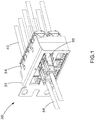
- FIG. 1 An exemplary embodiment is illustrated in Fig. 1 , which shows a communication system 30, which includes a patch panel 32 with jacks 34 and corresponding RJ45 plugs 36. Respective cables 38 are terminated to plugs 36, and respective cables 40 are terminated to jacks 34. Once a plug 36 mates with a jack 34 data can flow in both directions through these connectors.
- the communication system 30 is illustrated in Fig. 1 as having a patch panel, alternative embodiments can include other active or passive equipment Examples of passive equipment can be, but are not limited to, modular patch panels, punch-down patch panels, coupler patch panels, wall jacks, etc.
- Examples of active equipment can be, but are not limited to, Ethernet switches, routers, servers, physical layer management systems, and power-over-Ethernet equipment as can be found in data centers and or telecommunications rooms; security devices (cameras and other sensors, etc.) and door access equipment; and telephones, computers, fax machines, printers, and other peripherals as can be found in workstation areas.
- Communication system 30 can further include cabinets, racks, cable management and overhead routing systems, and other such equipment.
- Fig. 1 The jack and plug combination of Fig. 1 is also shown in Fig. 2 which illustrates the network jack 34 mated with the RJ45 plug 36. Note that in this figure, the orientation of the network jack 34 and the RJ45 plug 36 is rotated 180° about the central axis of cable 40 as compared to the orientation of Fig. 1 .
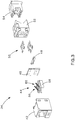
- Fig. 3 illustrates an exploded view of the network jack 34, which includes a front housing 42, a front sled subassembly 44, a printed circuit board (PCB) 46 (which in some embodiments may have crosstalk compensation components thereon), an insulation displacement contact (IDC) support 48, IDCs 50, a rear housing 52, and a wire cap 54.
- the front sled subassembly 44 includes a first set of PICs 56 and a second set of PICs 60, and a front sled 58 which can be made from any suitable material including, but not limited to, plastic.
- jack 34 can additionally include alien crosstalk-reducing materials such as a foil.
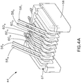
- Figs. 4A , 4B , and 4C illustrate the front sled subassembly 44 with PICs 56,60 and the front sled 58 in greater detail.
- the subscript numbers for each PIC 56 and 60 correspond to the RJ45 pin positions as defined by ANSI/TIA-568-C.2.
- PICs 56 have a configuration that is different from the configuration of PICs 60. More specifically, PICs 56 may be referred to as "front-rotated,” implying that those PICs generally flex about the front region 57 of the sled 58 when mated to a corresponding plug.
- Fig. 4A , 4B , and 4C illustrate the front sled subassembly 44 with PICs 56,60 and the front sled 58 in greater detail.
- the subscript numbers for each PIC 56 and 60 correspond to the RJ45 pin positions as defined by ANSI/TIA-568-C.2.
- PICs 56 have a configuration that
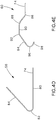
- Each PIC 56 includes a compliant pin 74, a lower beam section 80, a free end section 84, and a flex section 82 connecting the lower beam section 80 and the free end section 84.
- the front-pivoting design of PICs 56 may allow the free ends 84 to undergo a greater degree of downward deflection prior to plastic deformation while also maintaining an acceptable normal force with an eight-position RJ45 plug interface. These features may be helpful in allowing a jack to retain its functionality after mating with a six-position plug which deflects PICs 56 1 and 56 8 to a degree that is greater than the remaining PICs. Likewise, these features may also be helpful in allowing a jack to retain its functionality after mating with a four-position plug (e.g., RJ9) which deflects PICs 56 1 , 56 2 , 56 7 , and 56 8 to a degree that is greater than the remaining PICs.
- a four-position plug e.g., RJ9
- the second set of PICs may be referred to as "back-rotated,” implying that those PICs generally flex in the rear section 59 of the sled 58.
- Fig. 4E illustrates a side profile of one of the PICs 60 (which is representative of the side profile of all the PICs 60).
- Each PIC 60 includes a compliant pin 74, a first flex section 86, a second flex section 88, an upper beam portion 90, a first linking section 92 which links the upper beam portion 90 to a leg 94, and a second linking portion 96 which links the leg 94 to a free end 98.
- PICs 60 allows RJ45 pairs 4:5 and 3:6 to have a shorter electrical path from the plug contacts of the plug 36 to the PCB 46.
- the shortened distance may help to reduce or otherwise assist in reducing undesired crosstalk which can originate and/or occur on the 4:5 and 3:6 pairs.
- Figs. 5 - 8 illustrate the assembly of the front sled subassembly 44 in accordance with one embodiment Note that while a certain order of assembly is described, one of ordinary skill will recognize that the order of at least some steps of the assembly process may be varied.
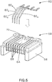
- the front sled subassembly 44 is fabricated by first inserting partially formed PICs 60 into the front sled 58. As shown in Fig. 5 , the PICs 60 are inserted from the top portion of the front sled 58.
- a front sled front comb 64 and a front sled rear comb 70 separate each PIC from adjacent PICs. When inserted into the sled 58, PICs 60 are at least partially supported by the rear section 59.
- the PICs 60 are further secured at the rear section 59 via securing features 62, as shown in Fig. 6A .
- securing feature 62 may be a staking feature.
- the second linking portions 96 and the free ends 98 of PICs 60 are wrapped around mandrels 68, as shown in Fig. 6B , to create front wraps 72.
- the front wraps 72 and the securing feature 62 provide at least some restrains for the PICs 60, holding them in position and reducing or eliminating unwanted degrees of freedom. Additionally, the front wraps 72 keep the PICs 60 from buckling inward during plug insertion by preventing the PICs 60 from moving in a backward direction.
- PICs 56 are joined to the front sled 58, as shown in Fig. 7 , such that the lower beam sections 80 run along the bottom of the front sled 58.
- the PICs 56 are fully joined to the front sled 58, they are secured by at least one securing feature 72 as shown in Fig. 8A .
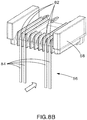
- the flex sections 82 and free ends 84 are wrapped around the front mandrels 68 as shown by the directional arrow in Fig. 8B .
- FIG. 9 Another embodiment of a jack having a front sled subassembly in accordance with an embodiment of the present invention is shown in Fig. 9 .
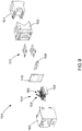
- This figure shows an exploded view of the network jack 134, which includes a front housing 142, a front sled subassembly 144, a PCB 146 (which in some embodiments may have crosstalk compensation components thereon), an IDC support 148, IDCs 150, a rear housing 152, and a wire cap 154.
- the front sled subassembly 144 includes a first set of PICs 156 and a second set of PICs 160, and a front sled 158 which can be made from any suitable material including, but not limited to, plastic.
- jack 134 can additionally include alien crosstalk-reducing materials such as a foil.
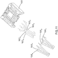
- Figs. 10 and 11 illustrate the front sled subassembly 144 with PICs 156,160 and the front sled 158 in greater detail.
- the subscript numbers for each PIC 156 and 160 correspond to the RJ45 pin positions as defined by ANSI/TIA-568-C.2.
- PICs 156 have a configuration that is similar to the PICs 56 of the previously described embodiment Accordingly, PICs 156 are front-rotated PICs which generally flex about the front region 157 of the sled 158 when mated to a corresponding plug, and may exhibit features and/or benefits which are same/similar to the PICs 56.
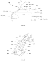
- Fig. 12 illustrates a side profile for PICs 160.
- PICs 160 comprise two separate profiles; a longer profile for PICs 160 4 and 160 6 , and a shorter profile for PICs 160 3 and 160 5 .
- each PIC 160 includes a compliant pin 174, a first flex section 186, a second flex section 188, an upper beam portion 190, a first linking section 192 which links the upper beam portion 190 to a leg 194, and a second linking portion 196 (which in some embodiments may be referred to as a "C" shaped bend) which links the leg 194 to a free end 198.
- a compliant pin 174 a first flex section 186, a second flex section 188, an upper beam portion 190, a first linking section 192 which links the upper beam portion 190 to a leg 194, and a second linking portion 196 (which in some embodiments may be referred to as a "C" shaped bend) which links the leg 194 to
- PICs 160 allows RJ45 pairs 4:5 and 3:6 to have a shorter electrical path from the plug contacts of the plug 36 to the PCB 146.
- the shortened distance may help to reduce or otherwise assist in reducing undesired crosstalk which can originate and/or occur on the 4:5 and 3:6 pairs.
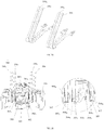
- Fig. 13A shows a front perspective view of the front sled 158.
- the front region 157 of the sled 158 includes mandrels 168 and a plurality of slots 169 which are at least partially separated by the front comb 164.
- the front comb 164 help separate and isolate each PIC from adjacent PICs, and slots 169 provide cavities which house portions of PICs 160 3 , 160 4 , 160 5 , and 160 6 .
- Slots 169 include floors 166, rear walls 167, and protrusion features 165 (which may also be referred to as latches).
- Each slot includes a pair of opposing latches 165 xA and 165 xB which are used to hold PICs 160 in close proximity to the floors 166.
- Latches 165 xA are positioned ahead of latches 165 xB so that each pair of corresponding latches is in a staggered formation. Such a configuration may help with PIC assembly, providing room for temporary, preferably non-plastic deformation of PICs 160 during their insertion into the front sled 158.
- the rear walls 167 may keep the PICs 160 from buckling inward during plug insertion by preventing the PICs 160 from moving in a backward direction.
- Fig. 13B illustrates the front sled 158 with the PICs 156,160 installed.
- latches 165 are molded rigid protrusions.
- other embodiments may implement latches 165 as soft, pliable, elastomeric, and/or moveable features which accomplish the task of providing at least some restraint of PICs 160 within their respective slots.
- each slot 169 having two latches 165 xA , 165 xB
- this configuration is merely exemplary and any slot 169 may include any desired number of latches.
- PICs 160 have a second linking portion 196 which can act as a spring when PICs 160 are deflected by the plug contacts of plug 36.
- the second linking portions 196 may help provide sufficient normal force and a robust interface between PICs 160 and the plug contacts of plug 36 over the full range of plug contact locations.
- PICs 160 are supported at their free ends 198 by floors 166. To reduce the relative amount of capacitive crosstalk coupling among PICs 160, physical staggering of the PICs 160 exists in the region of the second linking portions 196 and the free ends 198.
- the staggered configuration is achieved by having the profiles of the second linking portions 196 3 , 196 5 of PICs 160 3 , 160 5 differ from the profiles of the second linking portions 196 4 , 196 6 of PICs 160 4 , 160 6 .
- the staggered configuration increases space between the crosstalk-causing PICs 160 thereby decreasing the amount of crosstalk coupling.
- the staggering of PICs 160 is also shown isometrically in Fig. 15 .
- Fig. 16 shows a rear isometric view of front sled subassembly 144.
- Rear comb 170 is a feature of the front sled 158 and separates each PIC 160 from adjacent PICs 160 in the rear section 159 of the sled.
- PICs 156 and 160 are affixed to the sled 158 by securing features 162.
- securing features 162 may be staking features. Note that in Fig. 16 all securing features 162 are illustrated as staking features. However, with the exception of securing feature 162 3 , all other securing features 162 are shown in their "as molded" state. Only 162 3 is shown staked as it would be after assembly. Accordingly, in an embodiment where the securing features 162 are staking features, all securing features 162 may resemble securing feature 162 3 in the final assembled state of the front sled subassembly 144.
- PICs 156 and 160 are joined to the front sled 158.
- PICs 156 are joined in a manner that is same/similar to the joining of the PICs 56 to the front sled 58 of the previously described embodiment
- the curvature of their second linking portions 196 must be at least partially formed prior to mating with the front sled 158 to ensure that the free ends 198 are properly positioned between the latches 165 and the floors 166.
- PICs 160 are joined to the front sled 158 allowing the free ends 198 to descend into the slots 169 and lock into position via latches 165. PICs 160 are further secured by the securing features 162 near the rear section 159 of the front sled 158. After the front sled subassembly 144 has been assembled, it can then be attached to a PCB 146 and thereafter installed into the jack 134 as previously described.
- FIG. 17 shows an exploded view of a jack 234, which includes a front housing 242, a front sled subassembly 244, a PCB 246 (which in some embodiments may have crosstalk compensation components thereon), an IDC support 248, IDCs 250, a rear housing 252, and a wire cap 254. Alien crosstalk-reducing materials may be used in the construction of jack 234.
- Figs. 18A - 20 illustrate the front sled subassembly 244 with PICs 256 and the front sled 258 in greater detail.
- the subscript numbers for each PIC 256 correspond to the RJ45 pin positions as defined by ANSI/TIA-568-C.2.
- the PICs 256 may be referred to as "back-rotated" as these PICs generally flex in the rear section 259 of the sled 258.
- Fig. 19 shows a side profile view for the front sled subassembly 244, illustrating that the subassembly includes PICs having two separate side profiles.
- PIC 256 1 has a side profile representative of PICs 256 4 , 256 6 , and 256 8 , and includes a compliant pin 274, a flex section 280, a plug contact zone 282, a leg 284, and a free end 286.
- PIC 256 2 has a side profile representative of PICs 256 3 , 256 5 , and 256 7 , and includes a compliant pin 274, a flexing section 288, a plug contact zone 282, a leg 284, and a free end 286.
- the free ends 286 are supported along the floor 290 located at the front region of the sled 258.
- Fig. 20 shows a top view of the front sled subassembly 244 illustrating additional features which may be present in the currently described embodiment.
- the sled 258 includes features to hold the PICs 256 in position, and reduce and/or eliminate unwanted degrees of freedom.
- the sled 258 includes a front comb 260 which serves to align respective PICs 256 in the y direction with respect to the coordinate legend 262.
- Rear combs 264 also present on the top portion 294 of the sled 258 as shown in Fig. 21 ) at least partially constrain PICs 256 in the x and/or y directions.
- PICs 256 3 and 256 5 still retain a degree of freedom in the - x direction, these PICs include "T" features 266 3 and 266 5 , respectively, positioned at the free ends 286 thereof.
- the "T” features 266 3 and 266 5 at least partially prevent PICs 256 3 and 256 5 from moving in the - x direction and into the comb 260.
- "T” features 266 1 and 266 8 also exist on PICs 256 1 and 256 8 , respectively, to help ensure that these PICs do not buckle in the - x direction when a six-position plug is inserted, and instead deflect down in a - z direction.
- Same or similar "T” features can also be implemented on PICs 256 2 and 256 7 to help the jack 234 have compatibility with a four-position plug.
- PICs 256 deflect in the - z direction when they make contact with the plug contacts of an RJ45 plug in the plug contact zone 282 (or with the housing of a plug in case of PICs 256 1 and 256 8 when a six-position plug is used).
- the free ends 286 of PICs 256 slide in the + x direction.
- the free end 286 can include a curved contact section 292 for making contact with the floor 290.
- Such a configuration may improve the physical performance of the jack 234 by allowing the free ends 286 to more-easily slide along the x direction.
- the support of the free ends 286 by the floor 290 can increase the normal force at the interface between the PICs 256 and the plug contacts of an RJ45 plug. This may be beneficial in ensuring a satisfactory electrical contact
- the front sled subassembly 244 includes a two-piece sled 258 which has a top portion 294 and a bottom portion 296.
- the top and bottom portions 294,296 help constrain PICs 256 in their respective positions.
- the top portion 294 and the bottom portion 296 are hingedly attached to one another via hinging features 270, and lock in a closed position via latches 272 and latch pockets 274.
- alternate embodiment may omit the hinging feature 270 and instead provide the top and bottom portions 294,296 as separate pieces.
- the locking of the two portions may be achieved by any other suitable means which may or may not rely on the latches 272 and latch pockets 274.
- the front sled 258 may be provided as one piece where the top and bottom portions are joined together by a bridge which is broken at the time of assembly.
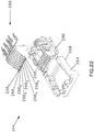
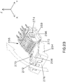
- Figs. 22 and 23 illustrate the assembly of the front sled subassembly 244.
- the front sled subassembly 244 is fabricated by first lowering the PICs 256 onto the bottom portion 296 of the sled 258. When the all the PICs 256 are positioned in their respective locations, the top portion 294 of the sled 258 is rotated about the hinging features 270, as shown by the arrow in Fig. 23 , until it rotates approximately 180° from its original open position and latches 272 engage the latch pockets 274, completing the assembly of the front sled subassembly 244.
- the engaging of the latches 272 and the latch pockets 274 locks the top and bottom portions 294,296, constraining the PICs and reducing and/or eliminating their undesired degrees of freedom.
- the constraining of the PICs is achieved at least partially by the bridge 276 (also see Figs. 18A and 18B ) which secures the PICs 256 in the region near the compliant pins 274 and restrains their movement in the z direction in that region, and the front bridge 298 which restrains the movement of the PICs in the z direction near the front portion of the sled 258.
- the front sled subassembly 244 After the front sled subassembly 244 has been assembled, it can then be attached to a PCB 246 and thereafter installed into the jack 234 as previously described.
- network jack 334 includes front housing 342, front sled subassembly 344, PCB 346, IDC support 348, IDCs 350, rear housing 352, and wire cap 354.
- Front sled subassembly 344 includes PICs 356, 360, 361, and a plastic sled 358.
- Jack 334, and other jacks described herein, can additionally include an alien crosstalk reducing foil as described in U.S. Patent No. 8,362,632 (Straka et al. ) entitled "Method and system for improving crosstalk attenuation within a plug/jack connection and between nearby plug/jack combinations".
- Fig. 25 illustrates front sled subassembly 344 with PICs 356, 360, 361, and sled 358.
- the subscript numbers of each PIC 356, 360, and 361 represent RJ45 pin positions as defined by ANSI/TIA-568-C.2.
- FIG. 26 A side view of front sled subassembly 344 is shown in Fig. 26 .
- the staggering of PICs 360 and 361 is also shown isometrically in Fig. 27 .
- PICs 361 have a front "C" shaped bend 368 that acts as a spring when PICs 361 are deflected by the contacts of plug 36.
- the "C" shaped bend 368 helps provide sufficient normal force and a robust interface between PICs 361 and the contacts of plug 36 over the full range of plug contact locations.
- PICs 361 are supported at their free end by floors of plastic sled 358.
- PICs 360 In order to further reduce capacitive and inductive crosstalk between these pairs in the present front sled assembly 344, PICs 360 have a front "S" shaped bend 369 that also acts as a spring when PICs 361 are deflected by contacts of plug 36, but an "S" shaped bend 369 provides further separation from crosstalk pairs.
- PIC 360 3 In order to increase compensation between pairs 3:5 and 4:6, PIC 360 3 includes jog 371 which decreases the physical distance between pairs 3:5 after the point of electrical contact 379 between the plug contacts of RJ45 plug 36 and PICs 356, 360, and 361. This feature may improve both capacitive and inductive compensation.
- PIC 361 6 includes jog 373 which decreases the physical distance between pairs 4:6 after the point of electrical contact 379. This feature may also improve both capacitive and inductive compensation.
- PIC 361 4 includes jog 375 which decreases the physical distance between pairs 4:6 past the point of electrical contact 379. This feature may improve capacitive compensation.
- PIC 360 5 includes jog 377 which decreases the physical distance between pairs 3:5 past the point of electrical contact 379. This feature may improve capacitive compensation.
- Jogs 375 and 377 result in a physical crossover of PICs 361 4 and 360 5 , prior to the point of electrical contact 379. This crossover of pairs provides a reduced distance between compensation pairs.
- Front sled assembly 344 staggers the compliant pins 372 of the PICs 356, 360, 361 onto three different planes as shown in Fig. 26 .
- This allows for further separation of crosstalk pairs by placing complaint pins 372 4 and 372 6 on the highest plane, complaint pins 372 3 and 372 5 on the middle plane, and complaint pins 372 1 , 372 2 , 372 7 , and 372 8 on the lowest plane. It is understood by those skilled in the art, that having the same electrical length of PICs 360 and 361 improves electrical balance in front sled subassembly 344.
- bend 374 has been added to PICs 361 4 and 361 6 to accommodate for the added electrical length needed to drop compliant pins 372 3 and 372 5 to the middle layer and to improve mechanical strength.
- PIC's 360 and 361 also have a varied initial plug contact height which can be seen in stagger 376. Stagger 376 changes the angle of deflection during electrical contact which minimizes crosstalk by increasing spacing between crosstalk pairs.
- FIG. 28 An isometric view of front rotated PICs 356 can be seen in Fig. 28 .
- Fig. 29 is a front isometric view of front sled subassembly 344.
- PICs 360 and 361 are positioned between front combs 362 and are retained by latches 364 (at least one latch 364 per each PIC 360,361, one indicated by subscript "a” and the other latch indicated by subscript "b"), shown in the detail view of Fig. 29 .
- Latches 364 are used to hold PICs 360,361 in close proximity to floors 367 of front sled 358 so that PICs 360 are protected within front combs 362 and do not become damaged during assembly handling, for example bowl feeding.
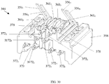
- Fig. 30 is a rear isometric view of front sled subassembly 344.
- Rear combs 370 are features of plastic sled 358 and separate each PIC 356, 360, and 361 from adjacent PICs.
- PICs 360 and 361 are affixed to plastic sled 358 by staking features 378.
- Fig. 30 also illustrates the three different levels of compliant pins 372.
- Fig. 31 illustrates a bottom isometric view of front sled subassembly 344.
- PICs 356 are affixed to plastic sled 358 staking features 380.
- Figs. 32-34 illustrate the PCB layout for PCB, showing the compensation for pairs 3:6 and 4:5.
Landscapes
- Coupling Device And Connection With Printed Circuit (AREA)
- Details Of Connecting Devices For Male And Female Coupling (AREA)
Description
- The present invention generally relates to the field of communication connectors, and more specifically to plug interface contact arrangements, front sled subassemblies having plug interface contacts for use with communication jacks, and communication jacks which employ such front sled assemblies.
- Communication connector such as RJ45 jacks, have been and continue to be readily employed in the communication industry. These jacks generally comprise a housing having an aperture for receiving a corresponding plug at one end, a means for terminating a communication cable at another end, and a means for transferring electrical signals between the plug and the communication cable.
- In an RJ45 jack, the means for transferring the electrical signals typically include eight plug interface contacts (PICs). While the eight PICs are designed to interface eight plug contacts positioned in an eight-position RJ45 plug, respectively, it is also possible to connect a six-position plug (e.g., RJ12, RJ25) to an RJ45 jack. However, when compared to an eight-position plug,
plug contacts 1 and 8 do not exist in a six-position plug. Therefore, in the locations where the plug contacts are not present, the jack PICs must undergo greater deflection as compared to locations where the plug contacts do exist This additional deflection can cause the outer PICs to plastically deform and cause damage (or otherwise prevent operation within certain specifications) to the jack if the deformation is significant enough. - Additionally, in some instances the positioning/arrangement of the PICs may have some effect on the amount of crosstalk produced within the plug/jack combination and/or how the crosstalk is compensated for. This can particularly be influenced by the proximity of the plug/jack mating point and the compensation network within the jack.
- Thus there exists a need for communication jacks with improved designs for plug interface contacts and corresponding compensation methods.
-
US 2012/0202389 relates to a spring assembly for a communications jack. -
US 6,769,937 B1 relates to a modular jack assembly including a housing having a mating face, and at least one conductive terminal having a body portion mounted in the housing and a contact arm cantilevered from the mating face. -
US 7,837,510 B1 relates to an electrical connector including an insulative housing extending in a front-to-back direction and including a rear base portion and a front tongue portion, and first and second sets of contacts held in the insulative housing. The first set of contacts includes at least one pair of differential contacts for transmitting high-speed signals. Each first contact includes a non-elastic first mating portion occupying a front section of the tongue portion. Each of the second set of contacts includes an elastic second mating portion located behind the non-elastic first mating portion along the front-to-back direction. The first and second sets of contacts are assembled to the insulative housing along opposite directions. The first and second body portions are provided with interference sections thereon to interferentially engage with the insulative housing. The first mating portion of each first contact is provided with interference sections to engage with the tongue portion of the insulative housing. - Accordingly, embodiments of the present invention are directed to communication connectors and/or internal components thereof. The invention is defined by the appended claims.
- In one embodiment, there is provided a communication jack comprising both front-rotated and back rotated plug interface contacts. This embodiment does not form part of the invention.
- In another embodiment, there is provided a communication jack comprising a two-piece front sled. This embodiment does not form part of the invention.
- In yet another embodiment, there is provided a communication jack that retains its functionality when mated with both eight-position and six-position plugs. This embodiment does not form part of the invention.
- In still yet another embodiment, there is provided a communication connector having a housing with an aperture for receiving a plug and a plurality of plug interface contacts at least partially received in the aperture. The plurality of plug interface contacts include respective ends proximal the aperture, the plurality of plug interface contacts have respective ends distal the aperture, the distal ends fixed within the connector, the proximal ends being supported and rotating relative to the distal ends, the proximal end including a spring section. In a variation of this embodiment, the communication connector is used in a communication system.
- In still yet another embodiment, there is provided a communication connector having a housing with an aperture for receiving a plug and a plurality of plug interface contacts at least partially received in the aperture. The plurality of plug interface contacts include respective ends proximal the aperture, the plurality of plug interface contacts have respective ends distal the aperture, the distal ends fixed within the connector, the proximal ends rotating relative to the distal ends, the proximal end including a contact zone, the contact zone being supported by a spring. This embodiment does not form part of the invention.
- These and other features, aspects, and advantages of the present invention will become better understood with reference to the following drawings, description, and any claims that may follow. Only the embodiment depicted from
Fig. 9 to Fig. 16 forms part of the invention. -
-
Fig. 1 illustrates a communication system. -
Fig. 2 illustrates a plug and jack combination. -
Fig. 3 illustrates an exploded view of a communication jack. -
Fig. 4A illustrates a front perspective view of a front sled subassembly. -
Fig. 4B illustrates a rear perspective view of the front sled subassembly ofFig. 4A . -
Fig. 4C illustrates an exploded view of the front sled subassembly of -
Figs. 4D and 4E illustrate side profiles of plug interface contacts of the front sled subassembly ofFig. 4A . -
Fig. 5 illustrates a step in the assembly process of the front sled subassembly ofFig. 4A . -
Figs. 6A and6B illustrate another step in the assembly process of the front sled subassembly ofFig. 4A . -
Fig. 7 illustrates yet another step in the assembly process of the front sled subassembly ofFig. 4A . -
Figs. 8A and8B illustrate still yet another step in the assembly process of the front sled subassembly ofFig. 4A . -
Fig. 9 illustrates an exploded view of a communication jack according to an embodiment of the present invention. -
Fig. 10 illustrates a front perspective view of a front sled subassembly according to an embodiment of the present invention. -
Fig. 11 illustrates an exploded view of the front sled subassembly ofFig. 10 . -
Fig. 12 illustrates side profiles of some of the plug interface contacts of the front sled subassembly ofFig. 10 . -
Fig. 13A illustrates a front perspective view of the front sled subassembly ofFig. 10 without the plug interface contacts installed. -
Fig. 13B illustrates a front perspective view of the front sled subassembly ofFig. 10 with the plug interface contacts installed. -
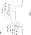
Fig. 14 illustrates a side profile view of the front sled subassembly ofFig. 10 . -
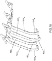
Fig. 15 illustrates some of the plug interface contacts of the front sled subassembly ofFig. 10 . -
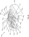
Fig. 16 illustrates a rear perspective view of the front sled subassembly ofFig. 10 . -
Fig. 17 illustrates an exploded view of a communication jack. -
Fig. 18A illustrates a front perspective view of a front sled subassembly. -
Fig. 18B illustrates a rear perspective view of the front sled subassembly ofFig. 18A . -
Fig. 19 illustrates a side profile view of the front sled subassembly ofFig. 18A . -
Fig. 20 illustrates a fragmentary top view of the front sled subassembly ofFig. 18A . -
Fig. 21 illustrates a front perspective view of the front sled subassembly ofFig. 18A in an open state. -
Fig. 22 illustrates a step in the assembly process of the front sled subassembly ofFig. 18A . -
Fig. 23 illustrates another step in the assembly process of the front sled subassembly ofFig. 18A . -
Fig. 24 illustrates an exploded view of a communication jack. -
Fig. 25 illustrates a front perspective view of a front sled subassembly. -
Fig. 26 illustrates a side view of the front sled subassembly ofFig. 25 . -
Fig. 27 illustrates a perspective view of an embodiment of plug interface contacts 4-6 of the front sled subassembly ofFig. 25 . -
Fig. 28 illustrates a perspective view of an embodiment ofplug interface contacts Fig. 25 . -
Fig. 29 illustrates a front perspective view of the front sled subassembly ofFig. 25 . -
Fig. 30 illustrates a rear perspective view of the front sled subassembly ofFig. 25 . -
Fig. 31 illustrates a bottom isometric view of the front sled subassembly ofFig. 25 . -
Fig. 32 illustrates a perspective view of an embodiment the printed circuit board ofFig. 25 . -
Fig. 33 illustrates a top view of the artwork for the four layers of the printed circuit board ofFig. 32 . -
Fig. 34 illustrates a schematic view of the printed circuit board ofFig. 33 . - An exemplary embodiment is illustrated in
Fig. 1 , which shows acommunication system 30, which includes apatch panel 32 withjacks 34 and corresponding RJ45 plugs 36.Respective cables 38 are terminated toplugs 36, andrespective cables 40 are terminated to jacks 34. Once aplug 36 mates with ajack 34 data can flow in both directions through these connectors. Although thecommunication system 30 is illustrated inFig. 1 as having a patch panel, alternative embodiments can include other active or passive equipment Examples of passive equipment can be, but are not limited to, modular patch panels, punch-down patch panels, coupler patch panels, wall jacks, etc. Examples of active equipment can be, but are not limited to, Ethernet switches, routers, servers, physical layer management systems, and power-over-Ethernet equipment as can be found in data centers and or telecommunications rooms; security devices (cameras and other sensors, etc.) and door access equipment; and telephones, computers, fax machines, printers, and other peripherals as can be found in workstation areas.Communication system 30 can further include cabinets, racks, cable management and overhead routing systems, and other such equipment. - The jack and plug combination of
Fig. 1 is also shown inFig. 2 which illustrates thenetwork jack 34 mated with theRJ45 plug 36. Note that in this figure, the orientation of thenetwork jack 34 and theRJ45 plug 36 is rotated 180° about the central axis ofcable 40 as compared to the orientation ofFig. 1 . -
Fig. 3 illustrates an exploded view of thenetwork jack 34, which includes afront housing 42, afront sled subassembly 44, a printed circuit board (PCB) 46 (which in some embodiments may have crosstalk compensation components thereon), an insulation displacement contact (IDC)support 48,IDCs 50, arear housing 52, and awire cap 54. In the currently described embodiment, thefront sled subassembly 44 includes a first set ofPICs 56 and a second set ofPICs 60, and afront sled 58 which can be made from any suitable material including, but not limited to, plastic. In alternate embodiments,jack 34 can additionally include alien crosstalk-reducing materials such as a foil. -
Figs. 4A ,4B , and4C illustrate thefront sled subassembly 44 withPICs front sled 58 in greater detail. The subscript numbers for eachPIC Fig. 4C ,PICs 56 have a configuration that is different from the configuration ofPICs 60. More specifically,PICs 56 may be referred to as "front-rotated," implying that those PICs generally flex about thefront region 57 of thesled 58 when mated to a corresponding plug.Fig. 4D illustrates a side profile of one of the PICs 56 (which is representative of the side profile of all the PICs 56). EachPIC 56 includes acompliant pin 74, alower beam section 80, afree end section 84, and aflex section 82 connecting thelower beam section 80 and thefree end section 84. - The front-pivoting design of
PICs 56 may allow the free ends 84 to undergo a greater degree of downward deflection prior to plastic deformation while also maintaining an acceptable normal force with an eight-position RJ45 plug interface. These features may be helpful in allowing a jack to retain its functionality after mating with a six-position plug which deflectsPICs PICs - The second set of PICs (PICs 60) may be referred to as "back-rotated," implying that those PICs generally flex in the
rear section 59 of thesled 58.Fig. 4E illustrates a side profile of one of the PICs 60 (which is representative of the side profile of all the PICs 60). EachPIC 60 includes acompliant pin 74, afirst flex section 86, asecond flex section 88, anupper beam portion 90, afirst linking section 92 which links theupper beam portion 90 to aleg 94, and asecond linking portion 96 which links theleg 94 to afree end 98. - The design of
PICs 60 allows RJ45 pairs 4:5 and 3:6 to have a shorter electrical path from the plug contacts of theplug 36 to thePCB 46. The shortened distance may help to reduce or otherwise assist in reducing undesired crosstalk which can originate and/or occur on the 4:5 and 3:6 pairs. -
Figs. 5 - 8 illustrate the assembly of thefront sled subassembly 44 in accordance with one embodiment Note that while a certain order of assembly is described, one of ordinary skill will recognize that the order of at least some steps of the assembly process may be varied. Thefront sled subassembly 44 is fabricated by first inserting partially formedPICs 60 into thefront sled 58. As shown inFig. 5 , thePICs 60 are inserted from the top portion of thefront sled 58. A frontsled front comb 64 and a front sledrear comb 70 separate each PIC from adjacent PICs. When inserted into thesled 58,PICs 60 are at least partially supported by therear section 59. ThePICs 60 are further secured at therear section 59 via securing features 62, as shown inFig. 6A . In some embodiments, securingfeature 62 may be a staking feature. To finalize the assembly of thePICs 60, thesecond linking portions 96 and the free ends 98 ofPICs 60 are wrapped aroundmandrels 68, as shown inFig. 6B , to create front wraps 72. The front wraps 72 and the securingfeature 62 provide at least some restrains for thePICs 60, holding them in position and reducing or eliminating unwanted degrees of freedom. Additionally, the front wraps 72 keep thePICs 60 from buckling inward during plug insertion by preventing thePICs 60 from moving in a backward direction. - After
PICs 60 are assembled,PICs 56 are joined to thefront sled 58, as shown inFig. 7 , such that thelower beam sections 80 run along the bottom of thefront sled 58. When thePICs 56 are fully joined to thefront sled 58, they are secured by at least one securingfeature 72 as shown inFig. 8A . Thereafter, theflex sections 82 and free ends 84 are wrapped around thefront mandrels 68 as shown by the directional arrow inFig. 8B . - Once both sets of
PICs front sled 58 they are attached to thePCB 46 via the compliant pins 74. Thereafter, thefront sled subassembly 44 and thePCB 46, together with the remaining components, are assembled into the front andrear housings jack 34. - Another embodiment of a jack having a front sled subassembly in accordance with an embodiment of the present invention is shown in
Fig. 9 . This figure shows an exploded view of thenetwork jack 134, which includes afront housing 142, afront sled subassembly 144, a PCB 146 (which in some embodiments may have crosstalk compensation components thereon), anIDC support 148,IDCs 150, arear housing 152, and awire cap 154. In the currently described embodiment, thefront sled subassembly 144 includes a first set ofPICs 156 and a second set ofPICs 160, and afront sled 158 which can be made from any suitable material including, but not limited to, plastic. In alternate embodiments,jack 134 can additionally include alien crosstalk-reducing materials such as a foil. -
Figs. 10 and11 illustrate thefront sled subassembly 144 with PICs 156,160 and thefront sled 158 in greater detail. The subscript numbers for eachPIC - As shown in
Fig. 11 ,PICs 156 have a configuration that is similar to thePICs 56 of the previously described embodiment Accordingly,PICs 156 are front-rotated PICs which generally flex about thefront region 157 of thesled 158 when mated to a corresponding plug, and may exhibit features and/or benefits which are same/similar to thePICs 56. -
Fig. 12 illustrates a side profile forPICs 160. Note, thatPICs 160 comprise two separate profiles; a longer profile forPICs PICs PIC 160 includes acompliant pin 174, afirst flex section 186, asecond flex section 188, anupper beam portion 190, afirst linking section 192 which links theupper beam portion 190 to aleg 194, and a second linking portion 196 (which in some embodiments may be referred to as a "C" shaped bend) which links theleg 194 to afree end 198. - The design of
PICs 160 allows RJ45 pairs 4:5 and 3:6 to have a shorter electrical path from the plug contacts of theplug 36 to thePCB 146. The shortened distance may help to reduce or otherwise assist in reducing undesired crosstalk which can originate and/or occur on the 4:5 and 3:6 pairs. -
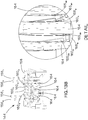
Fig. 13A shows a front perspective view of thefront sled 158. Thefront region 157 of thesled 158 includesmandrels 168 and a plurality ofslots 169 which are at least partially separated by thefront comb 164. Thefront comb 164 help separate and isolate each PIC from adjacent PICs, andslots 169 provide cavities which house portions ofPICs Slots 169 includefloors 166,rear walls 167, and protrusion features 165 (which may also be referred to as latches). Each slot includes a pair of opposinglatches PICs 160 in close proximity to thefloors 166.Latches 165xA are positioned ahead oflatches 165xB so that each pair of corresponding latches is in a staggered formation. Such a configuration may help with PIC assembly, providing room for temporary, preferably non-plastic deformation ofPICs 160 during their insertion into thefront sled 158. Therear walls 167 may keep thePICs 160 from buckling inward during plug insertion by preventing thePICs 160 from moving in a backward direction.Fig. 13B illustrates thefront sled 158 with the PICs 156,160 installed. - In the currently described embodiment, latches 165 are molded rigid protrusions. However, other embodiments may implement
latches 165 as soft, pliable, elastomeric, and/or moveable features which accomplish the task of providing at least some restraint ofPICs 160 within their respective slots. Furthermore, while the currently described embodiment illustrates eachslot 169 having twolatches slot 169 may include any desired number of latches. - As shown in the side views of
Figs. 12 and14 ,PICs 160 have asecond linking portion 196 which can act as a spring whenPICs 160 are deflected by the plug contacts ofplug 36. Thesecond linking portions 196 may help provide sufficient normal force and a robust interface betweenPICs 160 and the plug contacts ofplug 36 over the full range of plug contact locations.PICs 160 are supported at theirfree ends 198 byfloors 166. To reduce the relative amount of capacitive crosstalk coupling amongPICs 160, physical staggering of thePICs 160 exists in the region of thesecond linking portions 196 and the free ends 198. In the current embodiment, the staggered configuration is achieved by having the profiles of thesecond linking portions PICs second linking portions PICs PICs 160 thereby decreasing the amount of crosstalk coupling. The staggering ofPICs 160 is also shown isometrically inFig. 15 . -
Fig. 16 shows a rear isometric view offront sled subassembly 144.Rear comb 170 is a feature of thefront sled 158 and separates eachPIC 160 fromadjacent PICs 160 in therear section 159 of the sled.PICs sled 158 by securingfeatures 162. In some embodiments, securingfeatures 162 may be staking features. Note that inFig. 16 all securingfeatures 162 are illustrated as staking features. However, with the exception of securingfeature 1623, all other securing features 162 are shown in their "as molded" state. Only 1623 is shown staked as it would be after assembly. Accordingly, in an embodiment where the securing features 162 are staking features, all securingfeatures 162 may resemble securingfeature 1623 in the final assembled state of thefront sled subassembly 144. - To assemble the
front sled subassembly 144,PICs front sled 158.PICs 156 are joined in a manner that is same/similar to the joining of thePICs 56 to thefront sled 58 of the previously described embodiment As forPICs 160, the curvature of theirsecond linking portions 196 must be at least partially formed prior to mating with thefront sled 158 to ensure that the free ends 198 are properly positioned between thelatches 165 and thefloors 166. When thesecond linking portions 196 are formed such that the free ends 198 can be properly positioned,PICs 160 are joined to thefront sled 158 allowing the free ends 198 to descend into theslots 169 and lock into position vialatches 165.PICs 160 are further secured by the securing features 162 near therear section 159 of thefront sled 158. After thefront sled subassembly 144 has been assembled, it can then be attached to aPCB 146 and thereafter installed into thejack 134 as previously described. - Yet another embodiment of a jack having a front sled subassembly in accordance with an embodiment is shown in
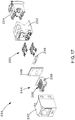
Fig. 17 . This figure shows an exploded view of ajack 234, which includes afront housing 242, afront sled subassembly 244, a PCB 246 (which in some embodiments may have crosstalk compensation components thereon), anIDC support 248,IDCs 250, arear housing 252, and awire cap 254. Alien crosstalk-reducing materials may be used in the construction ofjack 234. -
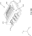
Figs. 18A - 20 illustrate thefront sled subassembly 244 withPICs 256 and thefront sled 258 in greater detail. The subscript numbers for eachPIC 256 correspond to the RJ45 pin positions as defined by ANSI/TIA-568-C.2. ThePICs 256 may be referred to as "back-rotated" as these PICs generally flex in therear section 259 of thesled 258. -
Fig. 19 shows a side profile view for thefront sled subassembly 244, illustrating that the subassembly includes PICs having two separate side profiles.PIC 2561 has a side profile representative ofPICs compliant pin 274, aflex section 280, aplug contact zone 282, aleg 284, and afree end 286.PIC 2562 has a side profile representative ofPICs compliant pin 274, aflexing section 288, aplug contact zone 282, aleg 284, and afree end 286. The free ends 286 are supported along thefloor 290 located at the front region of thesled 258. -
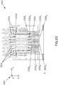
Fig. 20 shows a top view of thefront sled subassembly 244 illustrating additional features which may be present in the currently described embodiment. In particular, thesled 258 includes features to hold thePICs 256 in position, and reduce and/or eliminate unwanted degrees of freedom. Thesled 258 includes afront comb 260 which serves to alignrespective PICs 256 in the y direction with respect to the coordinatelegend 262. Rear combs 264 (also present on thetop portion 294 of thesled 258 as shown inFig. 21 ) at least partially constrainPICs 256 in the x and/or y directions. SincePICs PICs comb 260. "T" features 2661 and 2668 also exist onPICs PICs jack 234 have compatibility with a four-position plug. - Referring back to
Fig. 19 ,PICs 256 deflect in the -z direction when they make contact with the plug contacts of an RJ45 plug in the plug contact zone 282 (or with the housing of a plug in case ofPICs PICs 256 deflect in the -z direction in thecontact zone 282 during the mating of a plug, the free ends 286 ofPICs 256 slide in the +x direction. Thefree end 286 can include acurved contact section 292 for making contact with thefloor 290. Such a configuration may improve the physical performance of thejack 234 by allowing the free ends 286 to more-easily slide along the x direction. Furthermore, the support of the free ends 286 by thefloor 290 can increase the normal force at the interface between thePICs 256 and the plug contacts of an RJ45 plug. This may be beneficial in ensuring a satisfactory electrical contact - Referring to
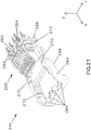
Fig. 21 , thefront sled subassembly 244 includes a two-piece sled 258 which has atop portion 294 and abottom portion 296. When joined together, the top and bottom portions 294,296 help constrainPICs 256 in their respective positions. In the currently described embodiment, thetop portion 294 and thebottom portion 296 are hingedly attached to one another via hinging features 270, and lock in a closed position vialatches 272 and latchpockets 274. However, alternate embodiment may omit thehinging feature 270 and instead provide the top and bottom portions 294,296 as separate pieces. Likewise, the locking of the two portions may be achieved by any other suitable means which may or may not rely on thelatches 272 and latchpockets 274. In yet another embodiment, thefront sled 258 may be provided as one piece where the top and bottom portions are joined together by a bridge which is broken at the time of assembly. -
Figs. 22 and23 illustrate the assembly of thefront sled subassembly 244. Thefront sled subassembly 244 is fabricated by first lowering thePICs 256 onto thebottom portion 296 of thesled 258. When the all thePICs 256 are positioned in their respective locations, thetop portion 294 of thesled 258 is rotated about the hinging features 270, as shown by the arrow inFig. 23 , until it rotates approximately 180° from its original open position and latches 272 engage the latch pockets 274, completing the assembly of thefront sled subassembly 244. The engaging of thelatches 272 and the latch pockets 274 locks the top and bottom portions 294,296, constraining the PICs and reducing and/or eliminating their undesired degrees of freedom. The constraining of the PICs is achieved at least partially by the bridge 276 (also seeFigs. 18A and18B ) which secures thePICs 256 in the region near thecompliant pins 274 and restrains their movement in the z direction in that region, and thefront bridge 298 which restrains the movement of the PICs in the z direction near the front portion of thesled 258. After thefront sled subassembly 244 has been assembled, it can then be attached to aPCB 246 and thereafter installed into thejack 234 as previously described. - In another embodiment (
Figs. 24-34 )network jack 334 includesfront housing 342,front sled subassembly 344,PCB 346,IDC support 348,IDCs 350,rear housing 352, andwire cap 354.Front sled subassembly 344 includesPICs plastic sled 358.Jack 334, and other jacks described herein, can additionally include an alien crosstalk reducing foil as described inU.S. Patent No. 8,362,632 (Straka et al. ) entitled "Method and system for improving crosstalk attenuation within a plug/jack connection and between nearby plug/jack combinations". -
Fig. 25 illustratesfront sled subassembly 344 withPICs sled 358. The subscript numbers of eachPIC - A side view of
front sled subassembly 344 is shown inFig. 26 . The staggering ofPICs Fig. 27 .PICs 361 have a front "C" shaped bend 368 that acts as a spring whenPICs 361 are deflected by the contacts ofplug 36. The "C" shaped bend 368 helps provide sufficient normal force and a robust interface betweenPICs 361 and the contacts ofplug 36 over the full range of plug contact locations.PICs 361 are supported at their free end by floors ofplastic sled 358. In order to further reduce capacitive and inductive crosstalk between these pairs in the presentfront sled assembly 344,PICs 360 have a front "S" shapedbend 369 that also acts as a spring whenPICs 361 are deflected by contacts ofplug 36, but an "S" shapedbend 369 provides further separation from crosstalk pairs. In order to increase compensation between pairs 3:5 and 4:6,PIC 3603 includesjog 371 which decreases the physical distance between pairs 3:5 after the point ofelectrical contact 379 between the plug contacts of RJ45 plug 36 andPICs PIC 3616 includesjog 373 which decreases the physical distance between pairs 4:6 after the point ofelectrical contact 379. This feature may also improve both capacitive and inductive compensation.PIC 3614 includesjog 375 which decreases the physical distance between pairs 4:6 past the point ofelectrical contact 379. This feature may improve capacitive compensation.PIC 3605 includesjog 377 which decreases the physical distance between pairs 3:5 past the point ofelectrical contact 379. This feature may improve capacitive compensation.Jogs PICs electrical contact 379. This crossover of pairs provides a reduced distance between compensation pairs. -
Front sled assembly 344 staggers the compliant pins 372 of thePICs Fig. 26 . This allows for further separation of crosstalk pairs by placing complaint pins 3724 and 3726 on the highest plane, complaint pins 3723 and 3725 on the middle plane, and complaint pins 3721, 3722, 3727, and 3728 on the lowest plane. It is understood by those skilled in the art, that having the same electrical length ofPICs front sled subassembly 344. In order to make all PICs with approximately the same electrical length,bend 374 has been added toPICs - An isometric view of front rotated
PICs 356 can be seen inFig. 28 . -
Fig. 29 is a front isometric view offront sled subassembly 344.PICs Fig. 29 . Latches 364 are used to hold PICs 360,361 in close proximity tofloors 367 offront sled 358 so thatPICs 360 are protected within front combs 362 and do not become damaged during assembly handling, for example bowl feeding. -
Fig. 30 is a rear isometric view offront sled subassembly 344. Rear combs 370 are features ofplastic sled 358 and separate eachPIC PICs plastic sled 358 by stakingfeatures 378.Fig. 30 also illustrates the three different levels of compliant pins 372. -
Fig. 31 illustrates a bottom isometric view offront sled subassembly 344.PICs 356 are affixed toplastic sled 358 staking features 380. -
Figs. 32-34 illustrate the PCB layout for PCB, showing the compensation for pairs 3:6 and 4:5. - Note that while several embodiments have been described, these embodiments are non-limiting (regardless of whether they have been labeled as exemplary or not), and there are alterations, permutations, and equivalents, which fall within the scope of this invention as defined by the appended claims. Additionally, the described embodiments should not be interpreted as mutually exclusive, and should instead be understood as potentially combinable if such combinations are permissive. It should also be noted that there are many alternative ways of implementing the methods and apparatuses of the present invention. It is therefore intended that the invention be interpreted as including all such alterations, permutations, and equivalents as fall within the scope of the appended claims.
Claims (10)
- A communication jack (134) configured to be mated with a RJ45 communication plug (36) having a plurality of plug contacts, said communication jack comprising:a housing (142) with an aperture for receiving said communication plug;a front sled (158) positioned in the housing; and
a plurality of plug interface contacts (160) at least partially received in said aperture, each of the plurality of plug interface contacts including a respective free end (198) proximal said aperture, and a respective end distal said aperture, said distal ends fixed within said jack, wherein each of said free ends includes a spring section (196), wherein each plug interface contact (160) is supported at said free end (198) by a floor (166) of a respective slot (169) included in the front sled (158), and wherein each slot (169) includes a pair of opposing latches (165) which hold the respective plug interface contact in proximity to the floor (166) of the respective slot (169). - The communication jack (134) of claim 1, wherein said spring section (196) has a C-shaped cross-section.
- The communication jack (134) of claim 1, wherein said plurality of plug interface contacts (160) include a first flex section (186), a second flex section (188) connected to said first flex section (186), an upper beam portion (190) connected to said second flex section (188).
- The communication jack (134) of claim 3, wherein said plurality of plug interface contacts (160) further include a first linking section (192) connecting said upper beam portion (190) to a leg (194), and a spring section (196) which links said leg (194) to said free end (198).
- The communication jack (134) of claim 4, further including a compliant pin (174) connected to said first flex section (186).
- A communication system, comprising:communication equipment; anda communication jack (134) as claimed in any preceding claim.
- The communication system of claim 6, wherein said spring section (196) has a C-shaped cross section.
- The communication system of claim 6, wherein said plurality of plug interface contacts (160) include a first flex section (186), a second flex section (188) connected to said first flex section (186), an upper beam portion (190) connected to said second flex section (188).
- The communication system of claim 8, wherein said plurality of plug interface contacts (160) further include a first linking section (192) connecting said upper beam portion (190) to a leg (194), and a spring section (196) which links said leg (194) to said free end (198).
- The communication system of claim 9, further including a compliant pin (174) connected to said first flex section (186).
Applications Claiming Priority (3)
| Application Number | Priority Date | Filing Date | Title |
|---|---|---|---|
| US201361775846P | 2013-03-11 | 2013-03-11 | |
| US14/203,057 US9379500B2 (en) | 2013-03-11 | 2014-03-10 | Front sled assemblies for communication jacks and communication jacks having front sled assemblies |
| PCT/US2014/023254 WO2014164701A1 (en) | 2013-03-11 | 2014-03-11 | Front sled assemblies for communication jacks and communication jacks having front sled assemblies |
Publications (2)
| Publication Number | Publication Date |
|---|---|
| EP2973883A1 EP2973883A1 (en) | 2016-01-20 |
| EP2973883B1 true EP2973883B1 (en) | 2020-01-01 |
Family
ID=51488350
Family Applications (1)
| Application Number | Title | Priority Date | Filing Date |
|---|---|---|---|
| EP14720302.0A Active EP2973883B1 (en) | 2013-03-11 | 2014-03-11 | Communication jack |
Country Status (4)
| Country | Link |
|---|---|
| US (2) | US9379500B2 (en) |
| EP (1) | EP2973883B1 (en) |
| JP (2) | JP6524056B2 (en) |
| WO (1) | WO2014164701A1 (en) |
Families Citing this family (3)
| Publication number | Priority date | Publication date | Assignee | Title |
|---|---|---|---|---|
| US9966703B2 (en) | 2014-10-17 | 2018-05-08 | Panduit Corp. | Communication connector |
| US11532916B2 (en) * | 2016-10-07 | 2022-12-20 | Panduit Corp. | High speed RJ45 connector |
| US9780466B1 (en) * | 2017-03-13 | 2017-10-03 | U.D.Electronic Corp. | RJ connector assembly |
Citations (2)
| Publication number | Priority date | Publication date | Assignee | Title |
|---|---|---|---|---|
| US6769937B1 (en) * | 2003-05-13 | 2004-08-03 | Molex Incorporated | Modular jack assembly for jack plugs with varying numbers of wires |
| US7837510B1 (en) * | 2009-05-20 | 2010-11-23 | Alltop Electronics (Suzhou) Co., Ltd | Electrical connector with improved contact arrangement |
Family Cites Families (42)
| Publication number | Priority date | Publication date | Assignee | Title |
|---|---|---|---|---|
| US5299956B1 (en) * | 1992-03-23 | 1995-10-24 | Superior Modular Prod Inc | Low cross talk electrical connector system |
| US5647770A (en) | 1995-12-29 | 1997-07-15 | Berg Technology, Inc. | Insert for a modular jack useful for reducing electrical crosstalk |
| US5779503A (en) * | 1996-12-18 | 1998-07-14 | Nordx/Cdt, Inc. | High frequency connector with noise cancelling characteristics |
| US5938479A (en) | 1997-04-02 | 1999-08-17 | Communications Systems, Inc. | Connector for reducing electromagnetic field coupling |
| US6368144B2 (en) | 1998-03-23 | 2002-04-09 | The Siemon Company | Enhanced performance modular outlet |
| GB2343558B (en) | 1998-11-04 | 2002-10-30 | Itt Mfg Enterprises Inc | Electrical connector |
| DK174367B1 (en) | 1999-12-30 | 2003-01-13 | Lk As | Electric circuit board as well as multi connectors |
| US6394853B1 (en) | 2000-08-04 | 2002-05-28 | Thomas & Betts International, Inc. | Data connector for selective switching between at least two distinct mating connector plugs |
| US6350158B1 (en) | 2000-09-19 | 2002-02-26 | Avaya Technology Corp. | Low crosstalk communication connector |
| US6558207B1 (en) | 2000-10-25 | 2003-05-06 | Tyco Electronics Corporation | Electrical connector having stamped electrical contacts with deformed sections for increased stiffness |
| US6896557B2 (en) | 2001-03-28 | 2005-05-24 | Ortronics, Inc. | Dual reactance low noise modular connector insert |
| US6431918B1 (en) * | 2001-04-27 | 2002-08-13 | Hon Hai Precisionind. Co., Ltd. | Modular jack connector meeting 1000base-T specifications |
| US6464541B1 (en) | 2001-05-23 | 2002-10-15 | Avaya Technology Corp. | Simultaneous near-end and far-end crosstalk compensation in a communication connector |
| FR2826788B1 (en) | 2001-06-28 | 2003-09-26 | Arnould App Electr | LOW CURRENT TYPE "MODULAR JACK" TYPE |
| US6409549B1 (en) | 2001-10-31 | 2002-06-25 | Hon Hai Precision Ind. Co., Ltd. | Electrical connector |
| US6869318B2 (en) | 2002-04-04 | 2005-03-22 | The Siemon Company | Outlet accommodating out-of-specification plugs |
| GB2398677A (en) | 2003-02-18 | 2004-08-25 | Hsu & Overmatt Co Ltd | Electrical connector with IDC pins |
| US6786775B1 (en) | 2003-06-10 | 2004-09-07 | Molex Incorporated | Modular jack assembly |
| US6739898B1 (en) | 2003-08-27 | 2004-05-25 | Hsing Chau Industrial Co., Ltd. | Telecommunication connector |
| EP1531523B1 (en) | 2003-11-13 | 2017-03-01 | TE Connectivity Germany GmbH | Lead connector for circuit board |
| US7182649B2 (en) | 2003-12-22 | 2007-02-27 | Panduit Corp. | Inductive and capacitive coupling balancing electrical connector |
| US6916209B1 (en) | 2004-01-23 | 2005-07-12 | Molex Incorporated | Electrical signal transmission system |
| US7153168B2 (en) | 2004-04-06 | 2006-12-26 | Panduit Corp. | Electrical connector with improved crosstalk compensation |
| US7166000B2 (en) | 2004-12-07 | 2007-01-23 | Commscope Solutions Properties, Llc | Communications connector with leadframe contact wires that compensate differential to common mode crosstalk |
| EP1693933A1 (en) | 2005-02-17 | 2006-08-23 | Reichle & De-Massari AG | Connector for data transmission via electrical wires |
| US7628656B2 (en) | 2006-03-10 | 2009-12-08 | Tyco Electronics Corporation | Receptacle with crosstalk optimizing contact array |
| US7407417B2 (en) | 2006-04-26 | 2008-08-05 | Tyco Electronics Corporation | Electrical connector having contact plates |
| US7341493B2 (en) * | 2006-05-17 | 2008-03-11 | Tyco Electronics Corporation | Electrical connector having staggered contacts |
| TWM301448U (en) | 2006-06-02 | 2006-11-21 | Jyh Eng Technology Co Ltd | Network connector |
| AU2007291879B2 (en) | 2006-09-01 | 2011-07-28 | Reichle & De-Massari Ag | Adapter and plug-in connection system |
| US7481678B2 (en) | 2007-06-14 | 2009-01-27 | Ortronics, Inc. | Modular insert and jack including bi-sectional lead frames |
| US7485010B2 (en) | 2007-06-14 | 2009-02-03 | Ortronics, Inc. | Modular connector exhibiting quad reactance balance functionality |
| US7503810B1 (en) | 2007-09-12 | 2009-03-17 | Commscope, Inc. Of North Carolina | Board edge termination back-end connection assemblies and communications jacks including such assemblies |
| WO2009039459A2 (en) | 2007-09-19 | 2009-03-26 | Leviton Manufacturing Co., Inc. | Internal crosstalk compensation circuit formed on a flexible printed circuit board positioned within a communications outlet, and methods and systems relating to same |
| US7601034B1 (en) | 2008-05-07 | 2009-10-13 | Ortronics, Inc. | Modular insert and jack including moveable reactance section |
| US7976348B2 (en) | 2008-05-07 | 2011-07-12 | Ortronics, Inc. | Modular insert and jack including moveable reactance section |
| US7686649B2 (en) | 2008-06-06 | 2010-03-30 | Tyco Electronics Corporation | Electrical connector with compensation component |
| US7927152B2 (en) | 2009-03-02 | 2011-04-19 | Tyco Electronics Corporation | Electrical connector with contact spacing member |
| US7967644B2 (en) | 2009-08-25 | 2011-06-28 | Tyco Electronics Corporation | Electrical connector with separable contacts |
| US8187040B2 (en) | 2010-01-11 | 2012-05-29 | Tyco Electronics Corporation | Mounting feature for the contact array of an electrical connector |
| US8425255B2 (en) | 2011-02-04 | 2013-04-23 | Leviton Manufacturing Co., Inc. | Spring assembly with spring members biasing and capacitively coupling jack contacts |
| CN102882039B (en) * | 2011-07-14 | 2015-05-06 | 富士康(昆山)电脑接插件有限公司 | Electric connector |
-
2014
- 2014-03-10 US US14/203,057 patent/US9379500B2/en active Active
- 2014-03-11 WO PCT/US2014/023254 patent/WO2014164701A1/en not_active Ceased
- 2014-03-11 JP JP2016501181A patent/JP6524056B2/en not_active Expired - Fee Related
- 2014-03-11 EP EP14720302.0A patent/EP2973883B1/en active Active
-
2016
- 2016-06-21 US US15/187,996 patent/US9800005B2/en not_active Expired - Fee Related
-
2018
- 2018-05-02 JP JP2018088739A patent/JP6469282B2/en not_active Expired - Fee Related
Patent Citations (2)
| Publication number | Priority date | Publication date | Assignee | Title |
|---|---|---|---|---|
| US6769937B1 (en) * | 2003-05-13 | 2004-08-03 | Molex Incorporated | Modular jack assembly for jack plugs with varying numbers of wires |
| US7837510B1 (en) * | 2009-05-20 | 2010-11-23 | Alltop Electronics (Suzhou) Co., Ltd | Electrical connector with improved contact arrangement |
Also Published As
| Publication number | Publication date |
|---|---|
| WO2014164701A1 (en) | 2014-10-09 |
| JP2016517140A (en) | 2016-06-09 |
| JP2018120873A (en) | 2018-08-02 |
| US9800005B2 (en) | 2017-10-24 |
| JP6524056B2 (en) | 2019-06-05 |
| EP2973883A1 (en) | 2016-01-20 |
| US20140256185A1 (en) | 2014-09-11 |
| US9379500B2 (en) | 2016-06-28 |
| US20160301171A1 (en) | 2016-10-13 |
| JP6469282B2 (en) | 2019-02-13 |
Similar Documents
| Publication | Publication Date | Title |
|---|---|---|
| EP2962367B1 (en) | Communication connector | |
| TWI489707B (en) | Rj-45 style communications jacks that are configured to receive both rj-45 and rj-11 style communications plugs | |
| US7905753B2 (en) | Coupler connector | |
| US6767257B2 (en) | Communication jack that withstands insertion of a communication plug that the jack is not specifically configured to mate with without being damage | |
| US8979569B2 (en) | Modular connectors and associated systems and methods | |
| US10153592B2 (en) | Communications connectors | |
| US7780480B2 (en) | Communications connector with improved contacts | |
| US8485850B2 (en) | Telecommunications connector | |
| US9800005B2 (en) | Front sled assemblies for communication jacks and communication jacks having front sled assemblies | |
| US10326242B2 (en) | RJ communication connectors | |
| EP2624377B1 (en) | Communication adapter |
Legal Events
| Date | Code | Title | Description |
|---|---|---|---|
| PUAI | Public reference made under article 153(3) epc to a published international application that has entered the european phase |
Free format text: ORIGINAL CODE: 0009012 |
|
| 17P | Request for examination filed |
Effective date: 20151008 |
|
| AK | Designated contracting states |
Kind code of ref document: A1 Designated state(s): AL AT BE BG CH CY CZ DE DK EE ES FI FR GB GR HR HU IE IS IT LI LT LU LV MC MK MT NL NO PL PT RO RS SE SI SK SM TR |
|
| AX | Request for extension of the european patent |
Extension state: BA ME |
|
| DAX | Request for extension of the european patent (deleted) | ||
| STAA | Information on the status of an ep patent application or granted ep patent |
Free format text: STATUS: EXAMINATION IS IN PROGRESS |
|
| 17Q | First examination report despatched |
Effective date: 20180104 |
|
| GRAP | Despatch of communication of intention to grant a patent |
Free format text: ORIGINAL CODE: EPIDOSNIGR1 |
|
| RIC1 | Information provided on ipc code assigned before grant |
Ipc: H01R 13/6461 20110101AFI20190704BHEP Ipc: H01R 107/00 20060101ALI20190704BHEP Ipc: H01R 24/64 20110101ALI20190704BHEP Ipc: H01R 27/00 20060101ALI20190704BHEP Ipc: H01R 13/6467 20110101ALI20190704BHEP |
|
| STAA | Information on the status of an ep patent application or granted ep patent |
Free format text: STATUS: GRANT OF PATENT IS INTENDED |
|
| INTG | Intention to grant announced |
Effective date: 20190808 |
|
| GRAS | Grant fee paid |
Free format text: ORIGINAL CODE: EPIDOSNIGR3 |
|
| GRAA | (expected) grant |
Free format text: ORIGINAL CODE: 0009210 |
|
| STAA | Information on the status of an ep patent application or granted ep patent |
Free format text: STATUS: THE PATENT HAS BEEN GRANTED |
|
| AK | Designated contracting states |
Kind code of ref document: B1 Designated state(s): AL AT BE BG CH CY CZ DE DK EE ES FI FR GB GR HR HU IE IS IT LI LT LU LV MC MK MT NL NO PL PT RO RS SE SI SK SM TR |
|
| REG | Reference to a national code |
Ref country code: GB Ref legal event code: FG4D |
|
| REG | Reference to a national code |
Ref country code: CH Ref legal event code: EP Ref country code: AT Ref legal event code: REF Ref document number: 1220973 Country of ref document: AT Kind code of ref document: T Effective date: 20200115 |
|
| REG | Reference to a national code |
Ref country code: IE Ref legal event code: FG4D |
|
| REG | Reference to a national code |
Ref country code: DE Ref legal event code: R096 Ref document number: 602014059263 Country of ref document: DE |
|
| PGFP | Annual fee paid to national office [announced via postgrant information from national office to epo] |
Ref country code: DE Payment date: 20200327 Year of fee payment: 7 Ref country code: GB Payment date: 20200327 Year of fee payment: 7 |
|
| REG | Reference to a national code |
Ref country code: NL Ref legal event code: MP Effective date: 20200101 |
|
| PGFP | Annual fee paid to national office [announced via postgrant information from national office to epo] |
Ref country code: FR Payment date: 20200325 Year of fee payment: 7 |
|
| REG | Reference to a national code |
Ref country code: LT Ref legal event code: MG4D |
|
| PG25 | Lapsed in a contracting state [announced via postgrant information from national office to epo] |
Ref country code: FI Free format text: LAPSE BECAUSE OF FAILURE TO SUBMIT A TRANSLATION OF THE DESCRIPTION OR TO PAY THE FEE WITHIN THE PRESCRIBED TIME-LIMIT Effective date: 20200101 Ref country code: LT Free format text: LAPSE BECAUSE OF FAILURE TO SUBMIT A TRANSLATION OF THE DESCRIPTION OR TO PAY THE FEE WITHIN THE PRESCRIBED TIME-LIMIT Effective date: 20200101 Ref country code: NO Free format text: LAPSE BECAUSE OF FAILURE TO SUBMIT A TRANSLATION OF THE DESCRIPTION OR TO PAY THE FEE WITHIN THE PRESCRIBED TIME-LIMIT Effective date: 20200401 Ref country code: PT Free format text: LAPSE BECAUSE OF FAILURE TO SUBMIT A TRANSLATION OF THE DESCRIPTION OR TO PAY THE FEE WITHIN THE PRESCRIBED TIME-LIMIT Effective date: 20200527 Ref country code: NL Free format text: LAPSE BECAUSE OF FAILURE TO SUBMIT A TRANSLATION OF THE DESCRIPTION OR TO PAY THE FEE WITHIN THE PRESCRIBED TIME-LIMIT Effective date: 20200101 Ref country code: CZ Free format text: LAPSE BECAUSE OF FAILURE TO SUBMIT A TRANSLATION OF THE DESCRIPTION OR TO PAY THE FEE WITHIN THE PRESCRIBED TIME-LIMIT Effective date: 20200101 Ref country code: RS Free format text: LAPSE BECAUSE OF FAILURE TO SUBMIT A TRANSLATION OF THE DESCRIPTION OR TO PAY THE FEE WITHIN THE PRESCRIBED TIME-LIMIT Effective date: 20200101 |
|
| PG25 | Lapsed in a contracting state [announced via postgrant information from national office to epo] |
Ref country code: HR Free format text: LAPSE BECAUSE OF FAILURE TO SUBMIT A TRANSLATION OF THE DESCRIPTION OR TO PAY THE FEE WITHIN THE PRESCRIBED TIME-LIMIT Effective date: 20200101 Ref country code: LV Free format text: LAPSE BECAUSE OF FAILURE TO SUBMIT A TRANSLATION OF THE DESCRIPTION OR TO PAY THE FEE WITHIN THE PRESCRIBED TIME-LIMIT Effective date: 20200101 Ref country code: SE Free format text: LAPSE BECAUSE OF FAILURE TO SUBMIT A TRANSLATION OF THE DESCRIPTION OR TO PAY THE FEE WITHIN THE PRESCRIBED TIME-LIMIT Effective date: 20200101 Ref country code: GR Free format text: LAPSE BECAUSE OF FAILURE TO SUBMIT A TRANSLATION OF THE DESCRIPTION OR TO PAY THE FEE WITHIN THE PRESCRIBED TIME-LIMIT Effective date: 20200402 Ref country code: IS Free format text: LAPSE BECAUSE OF FAILURE TO SUBMIT A TRANSLATION OF THE DESCRIPTION OR TO PAY THE FEE WITHIN THE PRESCRIBED TIME-LIMIT Effective date: 20200501 Ref country code: BG Free format text: LAPSE BECAUSE OF FAILURE TO SUBMIT A TRANSLATION OF THE DESCRIPTION OR TO PAY THE FEE WITHIN THE PRESCRIBED TIME-LIMIT Effective date: 20200401 |
|
| REG | Reference to a national code |
Ref country code: DE Ref legal event code: R097 Ref document number: 602014059263 Country of ref document: DE |
|
| PG25 | Lapsed in a contracting state [announced via postgrant information from national office to epo] |
Ref country code: ES Free format text: LAPSE BECAUSE OF FAILURE TO SUBMIT A TRANSLATION OF THE DESCRIPTION OR TO PAY THE FEE WITHIN THE PRESCRIBED TIME-LIMIT Effective date: 20200101 Ref country code: RO Free format text: LAPSE BECAUSE OF FAILURE TO SUBMIT A TRANSLATION OF THE DESCRIPTION OR TO PAY THE FEE WITHIN THE PRESCRIBED TIME-LIMIT Effective date: 20200101 Ref country code: DK Free format text: LAPSE BECAUSE OF FAILURE TO SUBMIT A TRANSLATION OF THE DESCRIPTION OR TO PAY THE FEE WITHIN THE PRESCRIBED TIME-LIMIT Effective date: 20200101 Ref country code: SM Free format text: LAPSE BECAUSE OF FAILURE TO SUBMIT A TRANSLATION OF THE DESCRIPTION OR TO PAY THE FEE WITHIN THE PRESCRIBED TIME-LIMIT Effective date: 20200101 Ref country code: EE Free format text: LAPSE BECAUSE OF FAILURE TO SUBMIT A TRANSLATION OF THE DESCRIPTION OR TO PAY THE FEE WITHIN THE PRESCRIBED TIME-LIMIT Effective date: 20200101 Ref country code: SK Free format text: LAPSE BECAUSE OF FAILURE TO SUBMIT A TRANSLATION OF THE DESCRIPTION OR TO PAY THE FEE WITHIN THE PRESCRIBED TIME-LIMIT Effective date: 20200101 Ref country code: MC Free format text: LAPSE BECAUSE OF FAILURE TO SUBMIT A TRANSLATION OF THE DESCRIPTION OR TO PAY THE FEE WITHIN THE PRESCRIBED TIME-LIMIT Effective date: 20200101 |
|
| REG | Reference to a national code |
Ref country code: CH Ref legal event code: PL |
|
| PLBE | No opposition filed within time limit |
Free format text: ORIGINAL CODE: 0009261 |
|
| STAA | Information on the status of an ep patent application or granted ep patent |
Free format text: STATUS: NO OPPOSITION FILED WITHIN TIME LIMIT |
|
| REG | Reference to a national code |
Ref country code: AT Ref legal event code: MK05 Ref document number: 1220973 Country of ref document: AT Kind code of ref document: T Effective date: 20200101 |
|
| 26N | No opposition filed |
Effective date: 20201002 |
|
| REG | Reference to a national code |
Ref country code: BE Ref legal event code: MM Effective date: 20200331 |
|
| PG25 | Lapsed in a contracting state [announced via postgrant information from national office to epo] |
Ref country code: LU Free format text: LAPSE BECAUSE OF NON-PAYMENT OF DUE FEES Effective date: 20200311 |
|
| PG25 | Lapsed in a contracting state [announced via postgrant information from national office to epo] |
Ref country code: LI Free format text: LAPSE BECAUSE OF NON-PAYMENT OF DUE FEES Effective date: 20200331 Ref country code: AT Free format text: LAPSE BECAUSE OF FAILURE TO SUBMIT A TRANSLATION OF THE DESCRIPTION OR TO PAY THE FEE WITHIN THE PRESCRIBED TIME-LIMIT Effective date: 20200101 Ref country code: IE Free format text: LAPSE BECAUSE OF NON-PAYMENT OF DUE FEES Effective date: 20200311 Ref country code: IT Free format text: LAPSE BECAUSE OF FAILURE TO SUBMIT A TRANSLATION OF THE DESCRIPTION OR TO PAY THE FEE WITHIN THE PRESCRIBED TIME-LIMIT Effective date: 20200101 Ref country code: CH Free format text: LAPSE BECAUSE OF NON-PAYMENT OF DUE FEES Effective date: 20200331 |
|
| PG25 | Lapsed in a contracting state [announced via postgrant information from national office to epo] |
Ref country code: PL Free format text: LAPSE BECAUSE OF FAILURE TO SUBMIT A TRANSLATION OF THE DESCRIPTION OR TO PAY THE FEE WITHIN THE PRESCRIBED TIME-LIMIT Effective date: 20200101 Ref country code: SI Free format text: LAPSE BECAUSE OF FAILURE TO SUBMIT A TRANSLATION OF THE DESCRIPTION OR TO PAY THE FEE WITHIN THE PRESCRIBED TIME-LIMIT Effective date: 20200101 Ref country code: BE Free format text: LAPSE BECAUSE OF NON-PAYMENT OF DUE FEES Effective date: 20200331 |
|
| REG | Reference to a national code |
Ref country code: DE Ref legal event code: R119 Ref document number: 602014059263 Country of ref document: DE |
|
| GBPC | Gb: european patent ceased through non-payment of renewal fee |
Effective date: 20210311 |
|
| PG25 | Lapsed in a contracting state [announced via postgrant information from national office to epo] |
Ref country code: DE Free format text: LAPSE BECAUSE OF NON-PAYMENT OF DUE FEES Effective date: 20211001 Ref country code: GB Free format text: LAPSE BECAUSE OF NON-PAYMENT OF DUE FEES Effective date: 20210311 Ref country code: FR Free format text: LAPSE BECAUSE OF NON-PAYMENT OF DUE FEES Effective date: 20210331 |
|
| PG25 | Lapsed in a contracting state [announced via postgrant information from national office to epo] |
Ref country code: TR Free format text: LAPSE BECAUSE OF FAILURE TO SUBMIT A TRANSLATION OF THE DESCRIPTION OR TO PAY THE FEE WITHIN THE PRESCRIBED TIME-LIMIT Effective date: 20200101 Ref country code: MT Free format text: LAPSE BECAUSE OF FAILURE TO SUBMIT A TRANSLATION OF THE DESCRIPTION OR TO PAY THE FEE WITHIN THE PRESCRIBED TIME-LIMIT Effective date: 20200101 Ref country code: CY Free format text: LAPSE BECAUSE OF FAILURE TO SUBMIT A TRANSLATION OF THE DESCRIPTION OR TO PAY THE FEE WITHIN THE PRESCRIBED TIME-LIMIT Effective date: 20200101 |
|
| PG25 | Lapsed in a contracting state [announced via postgrant information from national office to epo] |
Ref country code: MK Free format text: LAPSE BECAUSE OF FAILURE TO SUBMIT A TRANSLATION OF THE DESCRIPTION OR TO PAY THE FEE WITHIN THE PRESCRIBED TIME-LIMIT Effective date: 20200101 Ref country code: AL Free format text: LAPSE BECAUSE OF FAILURE TO SUBMIT A TRANSLATION OF THE DESCRIPTION OR TO PAY THE FEE WITHIN THE PRESCRIBED TIME-LIMIT Effective date: 20200101 |