EP2973595B1 - Passive techniques for long-term reactor cooling - Google Patents
Passive techniques for long-term reactor cooling Download PDFInfo
- Publication number
- EP2973595B1 EP2973595B1 EP14810719.6A EP14810719A EP2973595B1 EP 2973595 B1 EP2973595 B1 EP 2973595B1 EP 14810719 A EP14810719 A EP 14810719A EP 2973595 B1 EP2973595 B1 EP 2973595B1
- Authority
- EP
- European Patent Office
- Prior art keywords
- pressure vessel
- water
- vessel
- central riser
- pwr
- Prior art date
- Legal status (The legal status is an assumption and is not a legal conclusion. Google has not performed a legal analysis and makes no representation as to the accuracy of the status listed.)
- Active
Links
Images



Classifications
-
- G—PHYSICS
- G21—NUCLEAR PHYSICS; NUCLEAR ENGINEERING
- G21C—NUCLEAR REACTORS
- G21C15/00—Cooling arrangements within the pressure vessel containing the core; Selection of specific coolants
- G21C15/18—Emergency cooling arrangements; Removing shut-down heat
-
- G—PHYSICS
- G21—NUCLEAR PHYSICS; NUCLEAR ENGINEERING
- G21C—NUCLEAR REACTORS
- G21C1/00—Reactor types
- G21C1/32—Integral reactors, i.e. reactors wherein parts functionally associated with the reactor but not essential to the reaction, e.g. heat exchangers, are disposed inside the enclosure with the core
-
- G—PHYSICS
- G21—NUCLEAR PHYSICS; NUCLEAR ENGINEERING
- G21C—NUCLEAR REACTORS
- G21C9/00—Emergency protection arrangements structurally associated with the reactor, e.g. safety valves provided with pressure equalisation devices
-
- Y—GENERAL TAGGING OF NEW TECHNOLOGICAL DEVELOPMENTS; GENERAL TAGGING OF CROSS-SECTIONAL TECHNOLOGIES SPANNING OVER SEVERAL SECTIONS OF THE IPC; TECHNICAL SUBJECTS COVERED BY FORMER USPC CROSS-REFERENCE ART COLLECTIONS [XRACs] AND DIGESTS
- Y02—TECHNOLOGIES OR APPLICATIONS FOR MITIGATION OR ADAPTATION AGAINST CLIMATE CHANGE
- Y02E—REDUCTION OF GREENHOUSE GAS [GHG] EMISSIONS, RELATED TO ENERGY GENERATION, TRANSMISSION OR DISTRIBUTION
- Y02E30/00—Energy generation of nuclear origin
- Y02E30/30—Nuclear fission reactors
Definitions
- the following relates to the nuclear power generation arts, nuclear reactor safety arts, nuclear reactor emergency core cooling (ECC) arts, and related arts.
- the nuclear reactor core In a loss of coolant accident (LOCA), the nuclear reactor core is to be kept immersed in water so as to provide for removal of decay heat and to prevent exposure of the fuel rods to air which can lead to chemical reactions and release of airborne radioactivity.
- the system which provides this water injection is referred to as the emergency core cooling (ECC) system.
- ECC emergency core cooling
- a refueling water storage tank RWST
- RWST refueling water storage tank
- the RWST is located above the reactor core so that the passive ECC system can operate by gravity-driven water flow.
- Water injected into the depressurized pressure vessel by the ECC system is converted to steam by decay heat from the nuclear reactor core.
- this steam is recaptured by condensing it into the RWST so as to form a closed-loop recirculating heat exchange system.
- some steam is lost from the break that caused the LOCA. This lost steam condenses inside the surrounding radiological containment, thereby contributing to heat transfer from the reactor core although not in a recirculating fashion.
- the water collects in a containment sump, and a sump pump is provided to recirculate the water back into the RWST.
- an apparatus comprising:
- an apparatus comprising:
- an apparatus comprises: a pressurized water reactor (PWR) comprising a pressure vessel containing a nuclear reactor core comprising fissile material; a radiological containment structure inside of which the PWR is disposed; an emergency core cooling system configured to respond to a vessel penetration break at the top of the pressure vessel that results in depressurization of the pressure vessel by draining water from a body of water through an injection line into the pressure vessel; and a barrier configured to operate concurrently with the emergency core cooling system to suppress flow of liquid water from the pressure vessel out the vessel penetration break at the top of the pressure vessel.
- PWR pressurized water reactor
- the barrier may comprise one or more of: (1) an extension of the injection line disposed inside the pressure vessel and passing through the central riser to drain water from the body of water into the central riser of the pressure vessel; (2) openings in a lower portion of a central riser arranged to shunt a portion of the upward flow in the central riser into a lower portion of the downcomer annulus; and (3) a surge line configured to provide fluid communication between a pressurizer volume at the top of the pressure vessel and the remainder of the pressure vessel, the surge line configured to direct water outboard toward a downcomer annulus.
- a method comprises operating a pressurized water reactor (PWR) comprising a pressure vessel containing a nuclear reactor core comprising fissile material, and responding to a vessel penetration break at the top of the pressure vessel that results in depressurization of the pressure vessel by operations including: draining water from a body of water through an injection line into the pressure vessel; and during the draining, suppressing flow of liquid water from the pressure vessel out the vessel penetration break.
- the suppressing may include generating a counterflow in the pressure vessel during the draining in a direction opposite a flow of coolant water in the pressure vessel during the operating, for example by injecting the water from the body of water into the central riser.
- the suppressing additionally or alternatively may comprise shunting a portion of the upward flow of coolant water in the central riser through holes in the central riser and into a lower portion of the downcomer annulus without the shunted water reaching a top of the central riser.
- the suppressing additionally or alternatively may comprise directing surge flow between a pressurizer volume and the remainder volume of the pressure vessel outboard toward a downcomer annulus.
- FIGURE 1 a cutaway perspective view is shown of an illustrative small modular reactor (SMR) 10 and an illustrative refueling water storage tank (RWST) 12 (typically, two or more RWSTs are provided for redundancy).
- the SMR unit 10 is of the pressurized water reactor (PWR) variety, and includes a pressure vessel 14 and one or more integral steam generators 16 disposed inside the pressure vessel 14 (that is, the illustrative SMR 10 is an integral PWR 10 ).
- PWR pressurized water reactor
- an external steam generator may be employed.
- the SMR 10 also includes an integral pressurizer 18 defining an integral pressurizer volume 19 at the top of the pressure vessel 14; alternatively, an external pressurizer may be employed that is connected at the top of the SMR 10 by suitable piping.
- the pressure vessel 14 contains a nuclear reactor core 20 comprising fissile material such as 235 U (typically in an alloy, composite, mixture, or other form) immersed in (primary) coolant water (more generally herein, simply "coolant” or “coolant water”). With the reactor core 20 immersed in coolant water, and when control rod drive mechanisms (CRDMs) 22 at least partially withdraw control rods made of neutron-absorbing material, a nuclear chain reaction is initiated in the nuclear reactor core 20 which heats the (primary) coolant water.
- CRDMs control rod drive mechanisms
- the illustrative CRDMs 22 are internal CRDMs, in which the CRDM unit including its motor 22m including both rotor and stator are disposed inside the pressure vessel 14, and guide frame supports 23 guide the portions of the control rods located above the core; in other embodiments, external CRDM units may be employed.
- a separate water flow (secondary coolant) enters and exits the steam generators 16 via feedwater inlet 24 and steam outlets 26, respectively.
- the secondary coolant flows through secondary coolant channels of the steam generator or generators 16, and is converted to steam by heat from the reactor core carried by the (primary) coolant water.
- the pressure vessel 14 of the illustrative integral PWR 10 includes a lower portion 30 housing the nuclear reactor core 20 and an upper portion 32 housing the steam generators 16, with a mid-flange 34 connecting the upper and lower portions of the pressure vessel; however, the pressure vessel may be otherwise constructed or otherwise configured.
- a primary coolant flow circuit F inside the pressure vessel 14 is defined by a cylindrical central riser 36 extending upward above the reactor core 20 and a downcomer annulus 38 defined between the central cylindrical riser 36 and the pressure vessel 14.
- the flow F may be driven by natural circulation (i.e. by primary coolant heated by the reactor core 20 rising through the central cylindrical riser 36, discharging at the top and flowing downward through the downcomer annulus 38 ), or may be assisted or driven by reactor coolant pumps (RCPs), such as illustrative RCPs including RCP casings 40 containing impellers driven by RCP motors 42.
- the RCPs may alternatively be located elsewhere along the primary coolant path, or omitted entirely in a natural circulation reactor.
- the illustrative SMR 10 is merely an illustrative example, and the disclosed ECC techniques are suitably employed with substantially any type of light water nuclear reactor.
- FIGURE 1 a diagrammatic sectional view is shown of the SMR 10 disposed in a radiological containment structure 50 (also referred to herein as "radiological containment” or simply “containment”) along with the refueling water storage tank (RWST) 12. While a single RWST 12 is illustrated, it is to be understood that two or more RWSTs may be disposed inside containment to provide redundancy and/or to provide a larger total volume of water.
- the RWST 12 serves multiple purposes. As the name implies, is provides water for use during routine refueling (that is, removal of spent fuel comprising the nuclear reactor core and its replacement with fresh fuel).
- the RWST 12 also serves as a water reserve for use during certain accident scenarios, such as a loss of heat sinking event in which the heat sinking via the steam generators 16 or other heat sinking pathway is interrupted causing the pressure and temperature in the reactor pressure vessel 14 to rise; or a loss of coolant accident (LOCA) in which a break occurs in a (relatively large-diameter) pipe or vessel penetration connected with the pressure vessel 14.
- LOCA loss of coolant accident
- FIGURE 1 diagrammatically illustrates the response to a LOCA comprising a break from which steam 52 (possibly in the form of a two-phase steam/water mixture 52 ) escapes.
- a LOCA is diagrammatically indicated as originating in the proximity of the integral pressurizer 18 at the top of the pressure vessel 14.
- the SMR 10 is designed to eliminate the possibility of a LOCA break occurring at an elevation equal to or lower than the top of the reactor core 20. This can be done by designing the pressure vessel 14 with all large-diameter vessel penetrations located above the top of the reactor core 20 (e.g., the steam generator couplings 24, 26 are so located in the embodiment of FIGURE 1 ).
- large diameter vessel penetrations are defined as vessel penetrations of diameter 1.8-inch or larger.
- passive integral isolation valves may be employed for large-diameter vessel penetrations, so that any pipe breakage at the vessel penetration is immediately and passively sealed by the integral isolation valve.
- the passive integral isolation valve may be constructed as a check valve built into the mounting flange (rather than in or connected by external piping that is susceptible to breakage) that operates passively to prevent outflow of coolant from the flange having the integral valve.
- the passive integral isolation valve can be constructed with a spring bias that maintains the valve in the open position against the pressure of fluid flowing out via the letdown line, with the spring bias chosen such that an increase in (differential) outward pressure above a threshold value overcomes the spring bias to passively close the valve.
- the integral isolation valve is preferably built into the mounting flange.
- any LOCA break occurs at an elevation well above the top of the reactor core 20.
- the only large-diameter vessel penetrations susceptible to a break constituting a LOCA are located at the integral pressurizer 18 at the top of the pressure vessel 14.
- the steam/water 52 that escapes from the integral pressurizer 18 of the pressure vessel 14 is contained by the radiological containment 50, and the released energy is ejected to an ultimate heat sink (UHS) 54 via a suitable transfer mechanism.
- UHS ultimate heat sink
- this heat transfer is achieved (at least in part) by direct thermal contact between the UHS 54 which comprises a large body of water located on top of and in thermal contact with the top of the containment 50.
- a passive emergency core cooling (ECC) is activated, which depressurizes the reactor 10 using valves connected to the pressurizer 18 (in the illustrative example of FIGURE 1 , or elsewhere in other reactor designs) to vent the pressure vessel 14 to the RWST 12.
- ECC passive emergency core cooling
- This operation is diagrammatically indicated by steam path 60 carrying steam (or two-phase steam/water mixture) from the pressurizer 18 to be re-condensed in the RWST 12.
- water is initially injected into the reactor vessel from two (for redundancy, or more than two for further redundancy) nitrogen pressurized intermediate pressure injection tanks (IPIT, of which one illustrative IPIT 64 is shown in FIGURE 1 ) to assure the reactor core 20 remains immersed in coolant water during the depressurization.
- IPIT intermediate pressure injection tanks
- the water in the IPIT 64 optionally includes boron or another neutron poison to facilitate rapid shutdown of the nuclear chain reaction.
- water in the RWST 12 (or RWSTs, if two or more redundant RWST units are provided inside containment) drains into the reactor vessel 14 via an injection line 66 running from the RWST 12 to the reactor pressure vessel, thus refilling the vessel 14.
- a downstream portion of the injection line 66 also provides the input path for water from the IPIT 64, in which case suitable valving is provided to valve off the IPIT 64 after initial depressurization is complete.
- the valving is optionally passive, e.g. automatically closing when the pressure in the pressure vessel 14 falls below a setpoint. It is also contemplated to connect the IPIT with the reactor pressure vessel via a separate line from the injection line 66.
- the water in the RWST(s) 12 provides long-term cooling for the reactor core 20.
- the RWST 12 is a large body of water conveniently located inside the radiological containment structure 50 and hence is an attractive body of water for use by the ECC system; however, it is alternatively contemplated to connect the injection line 66 to another suitably large body of water that is located at an elevated position respective to the reactor core 20 so as to be drained into the pressure vessel 14 so as to provide emergency core cooling (ECC).
- ECC emergency core cooling
- the volume capacity of the RWST(s) 12 is designed to be sufficient to remove decay heat for a design time interval, e.g. 72 hours in some embodiments, or 14 days in other embodiments, without the need to recirculate water from a containment sump using sump pumps. This avoids the potential for transferring contaminants from the sump into the RWST.
- the ECC system relies upon gravity feed of water from the RWST 12 into the pressure vessel 14, it is necessary for the water level in the RWST 12 to be higher than the water level in the pressure vessel 14 in order for the ECC to operate.
- the initial water level in the RWST 12 is higher than the top of the pressure vessel 14 - in such embodiments, it is expected that the water level in the reactor vessel 14 will rise to the top of the pressurizer 18 and liquid water will flow out through the LOCA break.
- the flow out of the break would transition from mostly water to essentially all steam. This transition allows efficient utilization of the RWST water inventory. Since the heat capacity of the water then includes the latent heat for converting the water to steam.
- the magnitude of the problem is illustrated by a simple calculation, performed for a nuclear island design substantially similar to that shown in FIGURE 1 , in which the RWST (or plurality of RWSTs) has a capacity of about 1,324,894 litres (about 350,000 gallons), the initial water level in the RWST is at an elevation of 28.9m (95 feet), and the LOCA break is at a point (10 feet) lower in elevation, i.e. at 25.9m (85 feet). At 48.9 °C (120°F), the water in the RWST has a density of 988.34Kg/m 3 (61.7 lb/ft 3 ) (pounds/cubic foot)).
- saturated water has a density of 957.90Kg/m 3 (59.8 lb/ft 3 ) and steam has a density of 0.61Kg/m 3 (0.038 lb/ft 3 ).
- the ECC inlet to the vessel that is, the inlet of the injection line 66 to the pressure vessel 14 in illustrative FIGURE 1
- the density inside the reactor would be 57.35Kg/m 3 (3.58 lb/ft 3 ).
- the water level in the RWST would need to drop to an elevation of about 10.36m (about 34 ft) (which is 2.13m (7 feet) below the bottom of the RWST in some contemplated embodiments) in order to reach an equilibrium static head.
- a barrier mechanism 70 is implemented to suppress the flow of liquid water in the central riser 36 (or other upward flow path of the circulating primary coolant) from passing upward to the LOCA break.
- the barrier 70 may take the various forms, as described in the following. In some embodiments (described herein with reference to FIGURE 2 ), the barrier 70 comprises a modification of the pathways connecting the volume contained by the central riser 36 with the internal pressurizer volume 19.
- the barrier 70 forms the barrier 70 as a direct physical barrier, i.e. a baffle or tortuous path that limits the flow of liquid water from the central riser 36 into the internal pressurizer 18.
- the barrier 70 comprises modifying the ECC system so that it injects water from the RWST 12 into the central riser 36 in a manner that tends to drive circulation in a direction opposing the primary coolant flow circuit F inside the pressure vessel 14. This forms the barrier 70 indirectly, by slowing or even reversing the velocity of the primary coolant flow circuit F so as to limit the flow of liquid water from the central riser 36 into the internal pressurizer 18.
- the barrier 70 comprises providing bypass valves that divert a portion of the upward flow leg of the primary coolant flow circuit F from the central riser 36 into the downcomer annulus 38. This again forms the barrier 70 indirectly, by reducing the volume of upward flow in the central riser 36 so as to limit the flow of liquid water from the central riser 36 into the internal pressurizer 18. It will be appreciated that these mechanisms are not mutually exclusive, and the barrier 70 may comprise a combination of two or more of these mechanisms or variants thereof.
- the amount of steam generated in the reactor vessel 14 after a LOCA is determined by the core decay heat. This cannot be altered by the designer without changing the power level of the plant.
- the quality in the riser 36 can be improved by increasing the flow of water within the riser, by constructing the pressure vessel 14 to be configured to entrain water with the steam.
- a flow path is provided with the barrier 70 so as to separate the steam and water at the top of the reactor vessel 14 allowing the water to flow to the bottom of the pressure vessel 14 where it can be entrained with steam in the core again.
- the high quality natural circulation path should interface with the pressurizer 18 in a way that allows the excess water to be separated and directed back to the bottom of the pressure vessel 14.
- this is difficult to achieve in the context of an integral pressurizer, because flow paths are designed to permit relatively free fluid communication between the volume contained in the central riser 36 and the volume 19 of the integral pressurizer 18.
- surge lines 86 are provided via which water passes, in a constricted manner e.g. by baffles or the like, to allow pressure in the pressurizer 18 and remainder of the pressure vessel 14 to reach an equilibrium.
- pressure control elements 88 e.g. resistive heaters, spargers, or the like, are operable to raise or lower the pressure in the pressurizer volume 19, with the surge lines 86 allowing these changes to transfer to the lower operational portion of the pressure vessel 14.
- the surge lines 86 allow water collected in the pressurizer to drain out through the surge lines 86. This flow is directed into the rising two-phase steam/water flow rising up in the central riser 36. This prohibits a natural flow of the water, increasing the average quality within the riser.
- the pressurizer surge line 86 is modified to discharge along paths 90 that direct the water through the reactor coolant pumps and then down the tubes of the steam generators 16.
- the modified surge lines 90 direct water outboard toward the downcomer annulus, and are also suitably employed in embodiments that do not employ RCPs or that locate RCPs elsewhere along the primary coolant flow circuit.
- These modified paths 90 can be used during normal reactor operation as the surge lines, or can be opened by passive valves in response to an overpressure condition.
- the paths 90 are omitted and instead passive overpressure shutoff valves are installed on the surge lines 86 to close these lines off during ECC operation so that only the stand pipes 80 provide steam transport pathways into the pressurizer volume 90.
- the inlet of the injection line 66 to the pressure vessel 14, which conventionally feeds into the downcomer annulus 38, is modified by adding an extension pipe 100 so as to feed into the central riser 36.
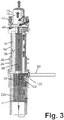
- the extension pipe 100 has a downwardly oriented outlet spigot 102 so as to direct the injected coolant from the RWST 12 downward. As diagrammatically indicated in FIGURE 3 , this tends to produce a coolant circulation flow -F oriented opposite to the direction from the primary coolant flow circuit F inside the pressure vessel 14 that is driven by the decay heat from the reactor core 20.
- the magnitude of the counterflow -F is sufficient to actually reverse the direction of circulation in the pressure vessel 14, while in other embodiments the magnitude of the counterflow -F is less than that of the flow F, but is sufficient to slow the velocity of the flow F.
- the counterflow -F aligns with the discharge of water through the pressurizer, and thereby has the effect of reducing the flow of water into the pressurizer volume 19 driven by the upward current of the flow F in the central riser 36.
- the counterflow -F can be interrupted when ECC flow is sufficiently low, or if some heat removal is available through a remedial operational mode of the steam generator (in embodiments that include the internal steam generator 16 ).
- a circulation pattern 108 is created using openings 110 in the core barrel (or other lower portion of the vessel central riser 36 ) so that a portion of the upward flow in the central riser 36 is shunted into the lower portion of the downcomer annulus 38 without passing upward into proximity with the pressurizer 18.
- the openings 110 can be holes, holes with flow diodes (i.e. check valves) or passively opened bypass valves to minimize normal bypass flow. This allows natural circulation flow 108 in the lower vessel.
- the flow 108 can be either in the normal direction (as illustrated) or in the reverse direction.
- the disclosed mechanisms for implementing the barrier 70 described with reference to FIGURES 2-4 are merely illustrative, and may be combined in various ways.
- the RCPs are located in a lower portion of the pressure vessel such that they are submerged during the ECC operation, and if electrical drive power is available, then it is contemplated to implement the barrier 70 at least in part by operating the RCPs in retrograde so as to provide the counterflow -F (see FIGURE 3 ) in an active fashion.
- the disclosed barrier 70 is effective for a pressurized water reactor (PWR) in the case of a LOCA break occurring at the top of the pressure vessel, e.g. in a vessel penetration into an integral pressurizer (as illustrated in FIGURES 1-4 ) or at piping between the top of the pressure vessel and an external pressurizer or at piping connecting at the top of such an externally pressurized vessel (variants not illustrated).
- PWR pressurized water reactor
- phraseology such as "top of the pressure vessel” is intended to encompass any break in a vessel penetration into the integral pressurizer 18 that is large enough to constitute a LOCA (that is, any break in a pipe of diameter greater than 1.8-inch).
- "top of the pressure vessel” is intended to encompass any break large enough to constitute a LOCA in a vessel penetration at an elevation high enough to be located above the primary coolant circuit in the pressure vessel.
- integral PWR systems in which steam generators 16 are disposed inside the pressure vessel 14 are illustrated, it is contemplated to employ the disclosed embodiments of the barrier 70 in PWR systems that utilize external steam generators.
Landscapes
- Physics & Mathematics (AREA)
- Engineering & Computer Science (AREA)
- Plasma & Fusion (AREA)
- General Engineering & Computer Science (AREA)
- High Energy & Nuclear Physics (AREA)
- Chemical & Material Sciences (AREA)
- Chemical Kinetics & Catalysis (AREA)
- Structure Of Emergency Protection For Nuclear Reactors (AREA)
Description
- This application claims the benefit of
U.S. Provisional Application No. 61/794,206 filed March 15, 2013 - The following relates to the nuclear power generation arts, nuclear reactor safety arts, nuclear reactor emergency core cooling (ECC) arts, and related arts.
- In a loss of coolant accident (LOCA), the nuclear reactor core is to be kept immersed in water so as to provide for removal of decay heat and to prevent exposure of the fuel rods to air which can lead to chemical reactions and release of airborne radioactivity. The system which provides this water injection is referred to as the emergency core cooling (ECC) system. In a typical arrangement, a refueling water storage tank (RWST) is located with the nuclear reactor inside radiological containment to provide water for use during reactor refueling, and this RWST also serves as a water source for the ECC system. The RWST is located above the reactor core so that the passive ECC system can operate by gravity-driven water flow.
- Water injected into the depressurized pressure vessel by the ECC system is converted to steam by decay heat from the nuclear reactor core. Preferably, this steam is recaptured by condensing it into the RWST so as to form a closed-loop recirculating heat exchange system. In practice, some steam is lost from the break that caused the LOCA. This lost steam condenses inside the surrounding radiological containment, thereby contributing to heat transfer from the reactor core although not in a recirculating fashion. In some embodiments, the water collects in a containment sump, and a sump pump is provided to recirculate the water back into the RWST.
- However, this approach is susceptible to failure if the diesel generators or other power source driving the sump pump fail, and moreover there is the potential to transfer contamination into the RWST that can interfere with operation of the ECC system.
- According to one aspect of the invention, there is provided an apparatus comprising:
- a pressurized water reactor (PWR) comprising a pressure vessel containing a nuclear reactor core comprising fissile material;
- a radiological containment structure inside of which the PWR is disposed;
- an emergency core cooling system configured to respond to a vessel penetration break at the top of the pressure vessel that results in depressurization of the pressure vessel by draining water from a body of water through an injection line into the pressure vessel; and
- a barrier configured to operate concurrently with the emergency core cooling system to suppress flow of liquid water from the pressure vessel out the vessel penetration break at the top of the pressure vessel, wherein the PWR further comprises a central riser disposed inside the pressure vessel and defining a coolant circulation path in which coolant water heated by the nuclear reactor core flows upward inside the central riser, exits a top opening of the central riser, and flows downward in a downcomer annulus defined between the central riser and the pressure vessel to return to the nuclear reactor core, and the barrier comprises:
an extension of the injection line disposed inside the pressure vessel and passing through the central riser to drain water from the body of water into the central riser of the pressure vessel. - According to another aspect of the invention, there is provided an apparatus comprising:
- a pressurized water reactor (PWR) comprising a pressure vessel containing a nuclear reactor core comprising fissile material;
- a radiological containment structure inside of which the PWR is disposed;
- an emergency core cooling system configured to respond to a vessel penetration break at the top of the pressure vessel that results in depressurization of the pressure vessel by draining water from a body of water through an injection line into the pressure vessel; and
- a barrier configured to operate concurrently with the emergency core cooling system to suppress flow of liquid water from the pressure vessel out the vessel penetration break at the top of the pressure vessel, wherein the PWR further comprises a central riser disposed inside the pressure vessel and defining a coolant circulation path in which coolant water heated by the nuclear reactor core flows upward inside the central riser, exits a top opening of the central riser, and flows downward in a downcomer annulus defined between the central riser and the pressure vessel to return to the nuclear reactor core, and the barrier comprises:
openings in a lower portion of the central riser arranged to shunt a portion of the upward flow in the central riser into a lower portion of the downcomer annulus. - According to another aspect of the invention, there is provided a method comprising:
- operating a pressurized water reactor (PWR) comprising a pressure vessel containing a nuclear reactor core comprising fissile material; and
- responding to a vessel penetration break at the top of the pressure vessel that results in depressurization of the pressure vessel by operations including:
- draining water from a body of water through an injection line into the pressure vessel, and
- during the draining, suppressing flow of liquid water from the pressure vessel out the vessel penetration break, wherein the operation of suppressing flow of liquid water from the pressure vessel out the vessel penetration break comprises:
during the draining, generating a counterflow in the pressure vessel in a direction opposite a flow of coolant water in the pressure vessel during the operating.
- According to another aspect of the invention, there is provided a method comprising:
- operating a pressurized water reactor (PWR) comprising a pressure vessel containing a nuclear reactor core comprising fissile material; and
- responding to a vessel penetration break at the top of the pressure vessel that results in depressurization of the pressure vessel by operations including:
- draining water from a body of water through an injection line (66) into the pressure vessel, and
- during the draining, suppressing flow of liquid water from the pressure vessel out the vessel penetration break, wherein the PWR further comprises a central riser disposed inside the pressure vessel, the operating comprises circulating coolant water upward inside the central riser and downward in a downcomer annulus defined between the central riser and the pressure vessel, and the operation of suppressing flow of liquid water from the pressure vessel out the vessel penetration break comprises:
shunting a portion of the upward flow of coolant water in the central riser through holes in the central riser and into a lower portion of the downcomer annulus without the shunted water reaching a top of the central riser.
- In one disclosed aspect, an apparatus comprises: a pressurized water reactor (PWR) comprising a pressure vessel containing a nuclear reactor core comprising fissile material; a radiological containment structure inside of which the PWR is disposed; an emergency core cooling system configured to respond to a vessel penetration break at the top of the pressure vessel that results in depressurization of the pressure vessel by draining water from a body of water through an injection line into the pressure vessel; and a barrier configured to operate concurrently with the emergency core cooling system to suppress flow of liquid water from the pressure vessel out the vessel penetration break at the top of the pressure vessel. The barrier may comprise one or more of: (1) an extension of the injection line disposed inside the pressure vessel and passing through the central riser to drain water from the body of water into the central riser of the pressure vessel; (2) openings in a lower portion of a central riser arranged to shunt a portion of the upward flow in the central riser into a lower portion of the downcomer annulus; and (3) a surge line configured to provide fluid communication between a pressurizer volume at the top of the pressure vessel and the remainder of the pressure vessel, the surge line configured to direct water outboard toward a downcomer annulus.
- In another disclosed aspect, a method comprises operating a pressurized water reactor (PWR) comprising a pressure vessel containing a nuclear reactor core comprising fissile material, and responding to a vessel penetration break at the top of the pressure vessel that results in depressurization of the pressure vessel by operations including: draining water from a body of water through an injection line into the pressure vessel; and during the draining, suppressing flow of liquid water from the pressure vessel out the vessel penetration break. The suppressing may include generating a counterflow in the pressure vessel during the draining in a direction opposite a flow of coolant water in the pressure vessel during the operating, for example by injecting the water from the body of water into the central riser. The suppressing additionally or alternatively may comprise shunting a portion of the upward flow of coolant water in the central riser through holes in the central riser and into a lower portion of the downcomer annulus without the shunted water reaching a top of the central riser. The suppressing additionally or alternatively may comprise directing surge flow between a pressurizer volume and the remainder volume of the pressure vessel outboard toward a downcomer annulus.
- The invention may take form in various components and arrangements of components, and in various process operations and arrangements of process operations. The drawings are only for purposes of illustrating preferred embodiments and are not to be construed as limiting the invention. This disclosure includes the following drawings.
-
FIGURE 1 shows a diagrammatic cutaway perspective view of an illustrative small modular reactor (SMR) disposed in a radiological containment structure along with a refueling water storage tank (RWST) with an emergency core cooling (ECC) system utilizing the RWST, and further including a diagrammatically indicated mechanism for suppressing loss of liquid water through a LOCA break. -
FIGURES 2-4 diagrammatically show illustrative embodiments of the mechanism for suppressing loss of liquid water through the LOCA break. - With reference to
FIGURE 1 , a cutaway perspective view is shown of an illustrative small modular reactor (SMR) 10 and an illustrative refueling water storage tank (RWST) 12 (typically, two or more RWSTs are provided for redundancy). TheSMR unit 10 is of the pressurized water reactor (PWR) variety, and includes apressure vessel 14 and one or moreintegral steam generators 16 disposed inside the pressure vessel 14 (that is, theillustrative SMR 10 is an integral PWR 10). Alternatively, an external steam generator may be employed. TheSMR 10 also includes anintegral pressurizer 18 defining anintegral pressurizer volume 19 at the top of thepressure vessel 14; alternatively, an external pressurizer may be employed that is connected at the top of theSMR 10 by suitable piping. Thepressure vessel 14 contains anuclear reactor core 20 comprising fissile material such as 235U (typically in an alloy, composite, mixture, or other form) immersed in (primary) coolant water (more generally herein, simply "coolant" or "coolant water"). With thereactor core 20 immersed in coolant water, and when control rod drive mechanisms (CRDMs) 22 at least partially withdraw control rods made of neutron-absorbing material, a nuclear chain reaction is initiated in thenuclear reactor core 20 which heats the (primary) coolant water. Theillustrative CRDMs 22 are internal CRDMs, in which the CRDM unit including itsmotor 22m including both rotor and stator are disposed inside thepressure vessel 14, and guide frame supports 23 guide the portions of the control rods located above the core; in other embodiments, external CRDM units may be employed. In the illustrativeintegral PWR 10, a separate water flow (secondary coolant) enters and exits thesteam generators 16 viafeedwater inlet 24 andsteam outlets 26, respectively. The secondary coolant flows through secondary coolant channels of the steam generator orgenerators 16, and is converted to steam by heat from the reactor core carried by the (primary) coolant water. Alternatively, if an external steam generator is employed then large-diameter closed-loop piping feeds (primary) coolant water from the pressure vessel to the external steam generator where heat from the primary coolant converts secondary coolant flow in the external steam generator to steam. Thepressure vessel 14 of the illustrativeintegral PWR 10 includes alower portion 30 housing thenuclear reactor core 20 and anupper portion 32 housing thesteam generators 16, with a mid-flange 34 connecting the upper and lower portions of the pressure vessel; however, the pressure vessel may be otherwise constructed or otherwise configured. - A primary coolant flow circuit F inside the
pressure vessel 14 is defined by a cylindricalcentral riser 36 extending upward above thereactor core 20 and adowncomer annulus 38 defined between the centralcylindrical riser 36 and thepressure vessel 14. The flow F may be driven by natural circulation (i.e. by primary coolant heated by thereactor core 20 rising through the centralcylindrical riser 36, discharging at the top and flowing downward through the downcomer annulus 38), or may be assisted or driven by reactor coolant pumps (RCPs), such as illustrative RCPs includingRCP casings 40 containing impellers driven byRCP motors 42. The RCPs may alternatively be located elsewhere along the primary coolant path, or omitted entirely in a natural circulation reactor. It is again noted that theillustrative SMR 10 is merely an illustrative example, and the disclosed ECC techniques are suitably employed with substantially any type of light water nuclear reactor. - With continuing reference to
FIGURE 1 , a diagrammatic sectional view is shown of theSMR 10 disposed in a radiological containment structure 50 (also referred to herein as "radiological containment" or simply "containment") along with the refueling water storage tank (RWST) 12. While asingle RWST 12 is illustrated, it is to be understood that two or more RWSTs may be disposed inside containment to provide redundancy and/or to provide a larger total volume of water. TheRWST 12 serves multiple purposes. As the name implies, is provides water for use during routine refueling (that is, removal of spent fuel comprising the nuclear reactor core and its replacement with fresh fuel). TheRWST 12 also serves as a water reserve for use during certain accident scenarios, such as a loss of heat sinking event in which the heat sinking via thesteam generators 16 or other heat sinking pathway is interrupted causing the pressure and temperature in thereactor pressure vessel 14 to rise; or a loss of coolant accident (LOCA) in which a break occurs in a (relatively large-diameter) pipe or vessel penetration connected with thepressure vessel 14. -
FIGURE 1 diagrammatically illustrates the response to a LOCA comprising a break from which steam 52 (possibly in the form of a two-phase steam/water mixture 52) escapes. InFIGURE 1 such a LOCA is diagrammatically indicated as originating in the proximity of theintegral pressurizer 18 at the top of thepressure vessel 14. In some embodiments theSMR 10 is designed to eliminate the possibility of a LOCA break occurring at an elevation equal to or lower than the top of thereactor core 20. This can be done by designing thepressure vessel 14 with all large-diameter vessel penetrations located above the top of the reactor core 20 (e.g., thesteam generator couplings FIGURE 1 ). As used herein, "large diameter" vessel penetrations are defined as vessel penetrations of diameter 1.8-inch or larger. Additionally or alternatively, passive integral isolation valves may be employed for large-diameter vessel penetrations, so that any pipe breakage at the vessel penetration is immediately and passively sealed by the integral isolation valve. For example, in the case of a make-up line or other water input line, the passive integral isolation valve may be constructed as a check valve built into the mounting flange (rather than in or connected by external piping that is susceptible to breakage) that operates passively to prevent outflow of coolant from the flange having the integral valve. In the case of a letdown line, the passive integral isolation valve can be constructed with a spring bias that maintains the valve in the open position against the pressure of fluid flowing out via the letdown line, with the spring bias chosen such that an increase in (differential) outward pressure above a threshold value overcomes the spring bias to passively close the valve. Again, the integral isolation valve is preferably built into the mounting flange. - With such measures, it can be ensured that any LOCA break occurs at an elevation well above the top of the
reactor core 20. In theillustrative pressure vessel 14, the only large-diameter vessel penetrations susceptible to a break constituting a LOCA are located at theintegral pressurizer 18 at the top of thepressure vessel 14. In such a LOCA, the steam/water 52 that escapes from theintegral pressurizer 18 of thepressure vessel 14 is contained by theradiological containment 50, and the released energy is ejected to an ultimate heat sink (UHS) 54 via a suitable transfer mechanism. In illustrativeFIGURE 1 , this heat transfer is achieved (at least in part) by direct thermal contact between theUHS 54 which comprises a large body of water located on top of and in thermal contact with the top of thecontainment 50. Additionally, a passive emergency core cooling (ECC) is activated, which depressurizes thereactor 10 using valves connected to the pressurizer 18 (in the illustrative example ofFIGURE 1 , or elsewhere in other reactor designs) to vent thepressure vessel 14 to theRWST 12. This operation is diagrammatically indicated bysteam path 60 carrying steam (or two-phase steam/water mixture) from the pressurizer 18 to be re-condensed in theRWST 12. Any excess pressure in theRWST 12 resulting from the venting of the pressure vessel to the RWST escapes via asteam vent 62 from the RWST. While depressurizing the reactor, water is initially injected into the reactor vessel from two (for redundancy, or more than two for further redundancy) nitrogen pressurized intermediate pressure injection tanks (IPIT, of which oneillustrative IPIT 64 is shown inFIGURE 1 ) to assure thereactor core 20 remains immersed in coolant water during the depressurization. The water in theIPIT 64 optionally includes boron or another neutron poison to facilitate rapid shutdown of the nuclear chain reaction. Once thereactor 10 is depressurized, water in the RWST 12 (or RWSTs, if two or more redundant RWST units are provided inside containment) drains into thereactor vessel 14 via aninjection line 66 running from theRWST 12 to the reactor pressure vessel, thus refilling thevessel 14. (Note that in illustrativeFIGURE 1 , a downstream portion of theinjection line 66 also provides the input path for water from theIPIT 64, in which case suitable valving is provided to valve off theIPIT 64 after initial depressurization is complete. The valving is optionally passive, e.g. automatically closing when the pressure in thepressure vessel 14 falls below a setpoint. It is also contemplated to connect the IPIT with the reactor pressure vessel via a separate line from theinjection line 66.) The water in the RWST(s) 12 provides long-term cooling for thereactor core 20. - The
RWST 12 is a large body of water conveniently located inside theradiological containment structure 50 and hence is an attractive body of water for use by the ECC system; however, it is alternatively contemplated to connect theinjection line 66 to another suitably large body of water that is located at an elevated position respective to thereactor core 20 so as to be drained into thepressure vessel 14 so as to provide emergency core cooling (ECC). - During the depressurization, it is expected that substantial primary coolant in the form of steam will exit the
pressure vessel 14 via the break that caused the LOCA. After startup of the ECC system, it is expected that steam will continue to exit thepressure vessel 14 via the break, albeit at a lower mass flow rate than during the initial depressurization. In some embodiments the volume capacity of the RWST(s) 12 is designed to be sufficient to remove decay heat for a design time interval, e.g. 72 hours in some embodiments, or 14 days in other embodiments, without the need to recirculate water from a containment sump using sump pumps. This avoids the potential for transferring contaminants from the sump into the RWST. - Because the ECC system relies upon gravity feed of water from the RWST 12 into the
pressure vessel 14, it is necessary for the water level in theRWST 12 to be higher than the water level in thepressure vessel 14 in order for the ECC to operate. In some embodiments, the initial water level in theRWST 12 is higher than the top of the pressure vessel 14 - in such embodiments, it is expected that the water level in thereactor vessel 14 will rise to the top of thepressurizer 18 and liquid water will flow out through the LOCA break. However, once the water level in theRWST 12 drops below the top of thepressurizer 18, it might be expected that the flow out of the break would transition from mostly water to essentially all steam. This transition allows efficient utilization of the RWST water inventory. Since the heat capacity of the water then includes the latent heat for converting the water to steam. - However, RELAP (Reactor Excursion and Leak Analysis Program) analysis of long-term cooling indicates that this is not necessarily the case; rather, a two-phase steam/water mixture with substantial water content continues to leave the LOCA break even after the water level in the
RWST 12 has drained below the level of the LOCA break. Without being limited to any particular theory of operation, it is believed that this effect is caused as follows. Decay heat from thereactor core 20 generates steam that reduces the density of the water above thereactor core 20. This effect prevents an equilibrium from being established between the water/steam column in thereactor vessel 14 and the water column in theRWST 12. The higher RWST driving head therefore continues to force water out of the break. - The magnitude of the problem is illustrated by a simple calculation, performed for a nuclear island design substantially similar to that shown in
FIGURE 1 , in which the RWST (or plurality of RWSTs) has a capacity of about 1,324,894 litres (about 350,000 gallons), the initial water level in the RWST is at an elevation of 28.9m (95 feet), and the LOCA break is at a point (10 feet) lower in elevation, i.e. at 25.9m (85 feet). At 48.9 °C (120°F), the water in the RWST has a density of 988.34Kg/m3 (61.7 lb/ft3) (pounds/cubic foot)). At 103.4kPa (15 psia), saturated water has a density of 957.90Kg/m3 (59.8 lb/ft3) and steam has a density of 0.61Kg/m3 (0.038 lb/ft3). If the ECC inlet to the vessel (that is, the inlet of theinjection line 66 to thepressure vessel 14 in illustrativeFIGURE 1 ) has an elevation of (1 feet and an average quality of 1% (that is, the water flowing in from the RWST is almost purely water with little or no steam content), then the density inside the reactor would be 57.35Kg/m3 (3.58 lb/ft3). In this case, the water level in the RWST would need to drop to an elevation of about 10.36m (about 34 ft) (which is 2.13m (7 feet) below the bottom of the RWST in some contemplated embodiments) in order to reach an equilibrium static head. - With returning reference to
FIGURE 1 , to compensate for this effect it is disclosed herein that the total quality in the central riser 36 (or other upward flow path of the circulating primary coolant) is reduced, or additional pressure drop is incorporated into the ECC injection system. Toward this end, abarrier mechanism 70, diagrammatically indicated inFIGURE 1 , is implemented to suppress the flow of liquid water in the central riser 36 (or other upward flow path of the circulating primary coolant) from passing upward to the LOCA break. Thebarrier 70 may take the various forms, as described in the following. In some embodiments (described herein with reference toFIGURE 2 ), thebarrier 70 comprises a modification of the pathways connecting the volume contained by thecentral riser 36 with theinternal pressurizer volume 19. This approach forms thebarrier 70 as a direct physical barrier, i.e. a baffle or tortuous path that limits the flow of liquid water from thecentral riser 36 into theinternal pressurizer 18. In some embodiments (described herein with reference toFIGURE 3 ), thebarrier 70 comprises modifying the ECC system so that it injects water from the RWST 12 into thecentral riser 36 in a manner that tends to drive circulation in a direction opposing the primary coolant flow circuit F inside thepressure vessel 14. This forms thebarrier 70 indirectly, by slowing or even reversing the velocity of the primary coolant flow circuit F so as to limit the flow of liquid water from thecentral riser 36 into theinternal pressurizer 18. In some embodiments (described herein with reference toFIGURE 4 ), thebarrier 70 comprises providing bypass valves that divert a portion of the upward flow leg of the primary coolant flow circuit F from thecentral riser 36 into thedowncomer annulus 38. This again forms thebarrier 70 indirectly, by reducing the volume of upward flow in thecentral riser 36 so as to limit the flow of liquid water from thecentral riser 36 into theinternal pressurizer 18. It will be appreciated that these mechanisms are not mutually exclusive, and thebarrier 70 may comprise a combination of two or more of these mechanisms or variants thereof. - In general, the amount of steam generated in the
reactor vessel 14 after a LOCA is determined by the core decay heat. This cannot be altered by the designer without changing the power level of the plant. However, the quality in theriser 36 can be improved by increasing the flow of water within the riser, by constructing thepressure vessel 14 to be configured to entrain water with the steam. Toward this end, a flow path is provided with thebarrier 70 so as to separate the steam and water at the top of thereactor vessel 14 allowing the water to flow to the bottom of thepressure vessel 14 where it can be entrained with steam in the core again. - The high quality natural circulation path should interface with the pressurizer 18 in a way that allows the excess water to be separated and directed back to the bottom of the
pressure vessel 14. However, this is difficult to achieve in the context of an integral pressurizer, because flow paths are designed to permit relatively free fluid communication between the volume contained in thecentral riser 36 and thevolume 19 of theintegral pressurizer 18. - With reference to
FIGURE 2 , and in particular the inset ofFIGURE 2 , when theRWST 12 has sufficient driving head to fill thereactor vessel 14, two-phase flow rises and enters the pressurizer 18 throughstand pipes 80 that extend through apump support plate 82. (More generally, thestand pipes 80 pass through a plate separating thepressurizer space 19 from the remainder of the pressure vessel volume. Note that in the inset ofFIGURE 2 theillustrative RCPs openings 84 in their place in thepump support plate 82. More generally, the RCPs may be located elsewhere, or may be omitted entirely in a natural circulation reactor.) Thesurge pipes 80 provide steam venting into thepressurizer space 19 during reactor depressurization. During normal operation,surge lines 86 are provided via which water passes, in a constricted manner e.g. by baffles or the like, to allow pressure in thepressurizer 18 and remainder of thepressure vessel 14 to reach an equilibrium. During normal operation,pressure control elements 88, e.g. resistive heaters, spargers, or the like, are operable to raise or lower the pressure in thepressurizer volume 19, with thesurge lines 86 allowing these changes to transfer to the lower operational portion of thepressure vessel 14. - During depressurization, however, the
surge lines 86 allow water collected in the pressurizer to drain out through the surge lines 86. This flow is directed into the rising two-phase steam/water flow rising up in thecentral riser 36. This prohibits a natural flow of the water, increasing the average quality within the riser. - In the embodiment of the
barrier 70 ofFIGURE 2 , thepressurizer surge line 86 is modified to discharge alongpaths 90 that direct the water through the reactor coolant pumps and then down the tubes of thesteam generators 16. (More generally, the modifiedsurge lines 90 direct water outboard toward the downcomer annulus, and are also suitably employed in embodiments that do not employ RCPs or that locate RCPs elsewhere along the primary coolant flow circuit.) These modifiedpaths 90 can be used during normal reactor operation as the surge lines, or can be opened by passive valves in response to an overpressure condition. In another alternative embodiment, thepaths 90 are omitted and instead passive overpressure shutoff valves are installed on thesurge lines 86 to close these lines off during ECC operation so that only thestand pipes 80 provide steam transport pathways into thepressurizer volume 90. - With reference to
FIGURE 3 , in another embodiment of thebarrier 70, the inlet of theinjection line 66 to thepressure vessel 14, which conventionally feeds into thedowncomer annulus 38, is modified by adding anextension pipe 100 so as to feed into thecentral riser 36. Optionally, theextension pipe 100 has a downwardly orientedoutlet spigot 102 so as to direct the injected coolant from theRWST 12 downward. As diagrammatically indicated inFIGURE 3 , this tends to produce a coolant circulation flow -F oriented opposite to the direction from the primary coolant flow circuit F inside thepressure vessel 14 that is driven by the decay heat from thereactor core 20. In some embodiments, the magnitude of the counterflow -F is sufficient to actually reverse the direction of circulation in thepressure vessel 14, while in other embodiments the magnitude of the counterflow -F is less than that of the flow F, but is sufficient to slow the velocity of the flow F. The counterflow -F aligns with the discharge of water through the pressurizer, and thereby has the effect of reducing the flow of water into thepressurizer volume 19 driven by the upward current of the flow F in thecentral riser 36. The counterflow -F can be interrupted when ECC flow is sufficiently low, or if some heat removal is available through a remedial operational mode of the steam generator (in embodiments that include the internal steam generator 16). - With reference to
FIGURE 4 , in another embodiment of thebarrier 70, acirculation pattern 108 is created usingopenings 110 in the core barrel (or other lower portion of the vessel central riser 36) so that a portion of the upward flow in thecentral riser 36 is shunted into the lower portion of thedowncomer annulus 38 without passing upward into proximity with thepressurizer 18. Theopenings 110 can be holes, holes with flow diodes (i.e. check valves) or passively opened bypass valves to minimize normal bypass flow. This allowsnatural circulation flow 108 in the lower vessel. Theflow 108 can be either in the normal direction (as illustrated) or in the reverse direction. - It is to be appreciated that the disclosed mechanisms for implementing the
barrier 70 described with reference toFIGURES 2-4 are merely illustrative, and may be combined in various ways. As another illustrative example, if the RCPs are located in a lower portion of the pressure vessel such that they are submerged during the ECC operation, and if electrical drive power is available, then it is contemplated to implement thebarrier 70 at least in part by operating the RCPs in retrograde so as to provide the counterflow -F (seeFIGURE 3 ) in an active fashion. (Although such operation may be relatively inefficient since the impeller blades are not designed for retrograde operation, the RCPs are nonetheless expected to be capable of generating counterflow -F sufficient to usefully reduce flow of water out the LOCA break.) The disclosedbarrier 70 is effective for a pressurized water reactor (PWR) in the case of a LOCA break occurring at the top of the pressure vessel, e.g. in a vessel penetration into an integral pressurizer (as illustrated inFIGURES 1-4 ) or at piping between the top of the pressure vessel and an external pressurizer or at piping connecting at the top of such an externally pressurized vessel (variants not illustrated). As used herein, phraseology such as "top of the pressure vessel" is intended to encompass any break in a vessel penetration into theintegral pressurizer 18 that is large enough to constitute a LOCA (that is, any break in a pipe of diameter greater than 1.8-inch). In the case of an externally pressurized vessel (that is, a pressure vessel that is pressurized using an external pressurizer connected via piping), "top of the pressure vessel" is intended to encompass any break large enough to constitute a LOCA in a vessel penetration at an elevation high enough to be located above the primary coolant circuit in the pressure vessel. Still further, while integral PWR systems in which steamgenerators 16 are disposed inside thepressure vessel 14 are illustrated, it is contemplated to employ the disclosed embodiments of thebarrier 70 in PWR systems that utilize external steam generators. - The preferred embodiments have been illustrated and described. Obviously, modifications and alterations will occur to others upon reading and understanding the preceding detailed description. It is intended that the invention be construed as including all such modifications and alterations insofar as they come within the scope of the appended claims.
Claims (14)
- An apparatus comprising:a pressurized water reactor (PWR) (10) comprising a pressure vessel (14) containing a nuclear reactor core (20) comprising fissile material;a radiological containment structure (50) inside of which the PWR (10) is disposed;an emergency core cooling system configured to respond to a vessel penetration break (14) at the top of the pressure vessel (14) that results in depressurization of the pressure vessel (14) by draining water from a body of water through an injection line (66) into the pressure vessel (14); anda barrier (70) configured to operate concurrently with the emergency core cooling system to suppress flow of liquid water from the pressure vessel (14) out the vessel penetration break at the top of the pressure vessel (14), wherein the PWR (10) further comprises a central riser (36) disposed inside the pressure vessel (14) and defining a coolant circulation path in which coolant water heated by the nuclear reactor core (20) flows upward inside the central riser (36), exits a top opening of the central riser, and flows downward in a downcomer annulus (38) defined between the central riser (36) and the pressure vessel (14) to return to the nuclear reactor core (20), and the barrier (70) comprises:
an extension (100) of the injection line (66) disposed inside the pressure vessel (14) and passing through the central riser (36) to drain water from the body of water into the central riser (36) of the pressure vessel (14). - The apparatus of claim 1 wherein the extension (100) of the injection line (66) includes a downwardly oriented outlet spigot (102) disposed inside the central riser (36).
- The apparatus of claim 1 wherein the body of water comprises a refueling water storage tank (RWST) (12) disposed with the PWR (10) in the radiological containment.
- The apparatus of claim 5 wherein the emergency core cooling system further includes:a pressurized water injection tank (64) configured to inject pressurized water into the pressure vessel (14) during depressurization of the pressure vessel (14);wherein the injection line (66) is configured to drain water from the RWST (12) into the pressure vessel (14) after the depressurization of the pressure vessel (14).
- The apparatus of claim 1 wherein the PWR (10) further comprises an integral pressurizer (18) defining a pressurizer volume (19) at the top of the pressure vessel (14), the integral pressurizer (18) including pressure control elements operable to control pressure in the pressurizer volume (19).
- The apparatus of claim 5 wherein the pressure vessel (14) includes passive integral isolation valves on vessel penetrations located below the integral pressurizer (18) whereby any vessel penetration break that results in depressurization of the pressure vessel (14) occurs at a vessel penetration to into the integral pressurizer (18) at the top of the pressure vessel (14).
- The apparatus of claim 1 wherein the barrier (70) further comprises:
openings (110) in a lower portion of the central riser (36) arranged to shunt a portion of the upward flow in the central riser (36) into a lower portion of the downcomer annulus(38). - An apparatus comprising:a pressurized water reactor (PWR) (10) comprising a pressure vessel (14) containing a nuclear reactor core (20) comprising fissile material;a radiological containment structure (52) inside of which the PWR (10) is disposed;an emergency core cooling system configured to respond to a vessel penetration break at the top of the pressure vessel (14) that results in depressurization of the pressure vessel (14) by draining water from a body of water through an injection line into the pressure vessel (14); anda barrier (70) configured to operate concurrently with the emergency core cooling system to suppress flow of liquid water from the pressure vessel (14) out the vessel penetration break at the top of the pressure vessel (14), wherein the PWR (10) further comprises a central riser (36) disposed inside the pressure vessel (14) and defining a coolant circulation path in which coolant water heated by the nuclear reactor core (20) flows upward inside the central riser (36), exits a top opening of the central riser (36), and flows downward in a downcomer annulus (38) defined between the central riser (36) and the pressure vessel (14) to return to the nuclear reactor core (20), and the barrier (70) comprises:
openings (110) in a lower portion of the central riser (36) arranged to shunt a portion of the upward flow in the central riser (36) into a lower portion of the downcomer annulus (38). - The apparatus of claim 9 wherein the PWR (10) further comprises:an integral pressurizer (18) defining a pressurizer volume (19) at the top of the pressure vessel (14), the integral pressurizer (18) including pressure control elements operable to control pressure in the pressurizer volume (19); andpassive integral isolation valves on vessel penetrations located below the integral pressurizer (18) whereby any vessel penetration break that results in depressurization of the pressure vessel (14) occurs at a vessel penetration to into the integral pressurizer (18) at the top of the pressure vessel (14).
- A method comprising:operating a pressurized water reactor (PWR) (10) comprising a pressure vessel (14) containing a nuclear reactor core (20) comprising fissile material; andresponding to a vessel penetration break at the top of the pressure vessel (14) that results in depressurization of the pressure vessel (14) by operations including:draining water from a body of water through an injection line (66) into the pressure vessel (14), andduring the draining, suppressing flow of liquid water from the pressure vessel (14) out the vessel penetration break, wherein the operation of suppressing flow of liquid water from the pressure vessel (14) out the vessel penetration break comprises:
during the draining, generating a counterflow in the pressure vessel (14) in a direction opposite a flow of coolant water in the pressure vessel (14) during the operating. - A method comprising:operating a pressurized water reactor (PWR) (10) comprising a pressure vessel (14) containing a nuclear reactor core (20) comprising fissile material; andresponding to a vessel penetration break at the top of the pressure vessel (14) that results in depressurization of the pressure vessel (14) by operations including:draining water from a body of water through an injection line (66) into the pressure vessel (14), andduring the draining, suppressing flow of liquid water from the pressure vessel (14) out the vessel penetration break, wherein the PWR (10) further comprises a central riser (36) disposed inside the pressure vessel (14), the operating comprises circulating coolant water upward inside the central riser (36) and downward in a downcomer annulus (38) defined between the central riser (36) and the pressure vessel (14), and the operation of suppressing flow of liquid water from the pressure vessel (14) out the vessel penetration break comprises:
injecting the water from the body of water into the central riser (36). - The method of claim 11 wherein the injecting comprises injecting the water from the body of water generally downward into the central riser (36).
- The method of claim 11 wherein the operation of suppressing flow of liquid water from the pressure vessel (14) out the vessel penetration break further comprises:
shunting a portion of the upward flow of coolant water in the central riser (36) through holes (110) in the central riser (36) and into a lower portion of the downcomer annulus (38) without the shunted water reaching a top of the central riser (36). - A method comprising:operating a pressurized water reactor (PWR) (10) comprising a pressure vessel (14) containing a nuclear reactor core (20) comprising fissile material; andresponding to a vessel penetration break at the top of the pressure vessel (14) that results in depressurization of the pressure vessel (14) by operations including:draining water from a body of water through an injection line (66) into the pressure vessel (14), andduring the draining, suppressing flow of liquid water from the pressure vessel (14) out the vessel penetration break, wherein the PWR (10) further comprises a central riser (36) disposed inside the pressure vessel (14), the operating comprises circulating coolant water upward inside the central riser (36) and downward in a downcomer annulus (38) defined between the central riser (36) and the pressure vessel (14), and the operation of suppressing flow of liquid water from the pressure vessel (14) out the vessel penetration break comprises:
shunting a portion of the upward flow of coolant water in the central riser (36) through holes (110) in the central riser (36) and into a lower portion of the downcomer annulus (38) without the shunted water reaching a top of the central riser (36).
Applications Claiming Priority (2)
| Application Number | Priority Date | Filing Date | Title |
|---|---|---|---|
| US201361794206P | 2013-03-15 | 2013-03-15 | |
| PCT/US2014/030393 WO2014200600A2 (en) | 2013-03-15 | 2014-03-17 | Passive techniques for long-term reactor cooling |
Publications (3)
| Publication Number | Publication Date |
|---|---|
| EP2973595A2 EP2973595A2 (en) | 2016-01-20 |
| EP2973595A4 EP2973595A4 (en) | 2016-12-14 |
| EP2973595B1 true EP2973595B1 (en) | 2019-01-02 |
Family
ID=54842962
Family Applications (1)
| Application Number | Title | Priority Date | Filing Date |
|---|---|---|---|
| EP14810719.6A Active EP2973595B1 (en) | 2013-03-15 | 2014-03-17 | Passive techniques for long-term reactor cooling |
Country Status (1)
| Country | Link |
|---|---|
| EP (1) | EP2973595B1 (en) |
Cited By (1)
| Publication number | Priority date | Publication date | Assignee | Title |
|---|---|---|---|---|
| WO2025145216A1 (en) * | 2023-12-30 | 2025-07-03 | Ge-Hitachi Nuclear Energy Americas Llc | Systems and methods for reducing coolant backflow through a pool-type reactor core |
Family Cites Families (3)
| Publication number | Priority date | Publication date | Assignee | Title |
|---|---|---|---|---|
| US8638898B2 (en) * | 2011-03-23 | 2014-01-28 | Babcock & Wilcox Mpower, Inc. | Emergency core cooling system for pressurized water reactor |
| US9583221B2 (en) * | 2011-06-15 | 2017-02-28 | Bwxt Nuclear Energy, Inc. | Integrated emergency core cooling system condenser for pressurized water reactor |
| US9558855B2 (en) * | 2011-11-10 | 2017-01-31 | Bwxt Nuclear Energy, Inc. | Pressurized water reactor with upper plenum including cross-flow blocking weir |
-
2014
- 2014-03-17 EP EP14810719.6A patent/EP2973595B1/en active Active
Non-Patent Citations (1)
| Title |
|---|
| None * |
Cited By (1)
| Publication number | Priority date | Publication date | Assignee | Title |
|---|---|---|---|---|
| WO2025145216A1 (en) * | 2023-12-30 | 2025-07-03 | Ge-Hitachi Nuclear Energy Americas Llc | Systems and methods for reducing coolant backflow through a pool-type reactor core |
Also Published As
| Publication number | Publication date |
|---|---|
| EP2973595A2 (en) | 2016-01-20 |
| EP2973595A4 (en) | 2016-12-14 |
Similar Documents
| Publication | Publication Date | Title |
|---|---|---|
| US12531165B2 (en) | Passive techniques for long-term reactor cooling | |
| JP6243903B2 (en) | Safety system of modular small furnace | |
| KR101215323B1 (en) | A nuclear reactor assembly including a nuclear reactor, an emergency cooling system for the nuclear reactor, and an emergency cooling method of the nuclear reactor | |
| US4473528A (en) | Passive containment system | |
| US9728281B2 (en) | Auxiliary condenser system for decay heat removal in a nuclear reactor | |
| US12387855B2 (en) | Refueling water storage tank (RWST) with tailored passive emergency core cooling (ECC) flow | |
| US20130301782A1 (en) | Defense in depth safety paradigm for nuclear reactor | |
| WO2010038358A1 (en) | Pressurized water nuclear power plant | |
| KR20140037825A (en) | Emergency core cooling systems for pressurized water reactor | |
| KR20150107855A (en) | Passive system for cooling the core of a nuclear reactor | |
| CN104969301A (en) | Pressurized water reactor depressurization system | |
| EP2973595A2 (en) | Passive techniques for long-term reactor cooling | |
| Malloy III et al. | Passive techniques for long-term reactor cooling | |
| Hau et al. | ICONE15-10650 UTILIZING NATURAL CIRCULATION IN ACR-1000 DESIGN |
Legal Events
| Date | Code | Title | Description |
|---|---|---|---|
| PUAI | Public reference made under article 153(3) epc to a published international application that has entered the european phase |
Free format text: ORIGINAL CODE: 0009012 |
|
| 17P | Request for examination filed |
Effective date: 20150911 |
|
| AK | Designated contracting states |
Kind code of ref document: A2 Designated state(s): AL AT BE BG CH CY CZ DE DK EE ES FI FR GB GR HR HU IE IS IT LI LT LU LV MC MK MT NL NO PL PT RO RS SE SI SK SM TR |
|
| AX | Request for extension of the european patent |
Extension state: BA ME |
|
| RIC1 | Information provided on ipc code assigned before grant |
Ipc: G21C 9/00 20060101AFI20160118BHEP |
|
| DAX | Request for extension of the european patent (deleted) | ||
| REG | Reference to a national code |
Ref country code: DE Ref legal event code: R079 Ref document number: 602014039240 Country of ref document: DE Free format text: PREVIOUS MAIN CLASS: G21C0015040000 Ipc: G21C0009000000 |
|
| A4 | Supplementary search report drawn up and despatched |
Effective date: 20161115 |
|
| RIC1 | Information provided on ipc code assigned before grant |
Ipc: G21C 15/18 20060101ALI20161109BHEP Ipc: G21C 9/00 20060101AFI20161109BHEP |
|
| STAA | Information on the status of an ep patent application or granted ep patent |
Free format text: STATUS: EXAMINATION IS IN PROGRESS |
|
| 17Q | First examination report despatched |
Effective date: 20171106 |
|
| GRAP | Despatch of communication of intention to grant a patent |
Free format text: ORIGINAL CODE: EPIDOSNIGR1 |
|
| STAA | Information on the status of an ep patent application or granted ep patent |
Free format text: STATUS: GRANT OF PATENT IS INTENDED |
|
| INTG | Intention to grant announced |
Effective date: 20180711 |
|
| GRAS | Grant fee paid |
Free format text: ORIGINAL CODE: EPIDOSNIGR3 |
|
| GRAA | (expected) grant |
Free format text: ORIGINAL CODE: 0009210 |
|
| STAA | Information on the status of an ep patent application or granted ep patent |
Free format text: STATUS: THE PATENT HAS BEEN GRANTED |
|
| AK | Designated contracting states |
Kind code of ref document: B1 Designated state(s): AL AT BE BG CH CY CZ DE DK EE ES FI FR GB GR HR HU IE IS IT LI LT LU LV MC MK MT NL NO PL PT RO RS SE SI SK SM TR |
|
| REG | Reference to a national code |
Ref country code: GB Ref legal event code: FG4D |
|
| REG | Reference to a national code |
Ref country code: CH Ref legal event code: EP Ref country code: AT Ref legal event code: REF Ref document number: 1085408 Country of ref document: AT Kind code of ref document: T Effective date: 20190115 |
|
| REG | Reference to a national code |
Ref country code: IE Ref legal event code: FG4D |
|
| REG | Reference to a national code |
Ref country code: DE Ref legal event code: R096 Ref document number: 602014039240 Country of ref document: DE |
|
| REG | Reference to a national code |
Ref country code: NL Ref legal event code: MP Effective date: 20190102 |
|
| REG | Reference to a national code |
Ref country code: LT Ref legal event code: MG4D |
|
| REG | Reference to a national code |
Ref country code: AT Ref legal event code: MK05 Ref document number: 1085408 Country of ref document: AT Kind code of ref document: T Effective date: 20190102 |
|
| PG25 | Lapsed in a contracting state [announced via postgrant information from national office to epo] |
Ref country code: NL Free format text: LAPSE BECAUSE OF FAILURE TO SUBMIT A TRANSLATION OF THE DESCRIPTION OR TO PAY THE FEE WITHIN THE PRESCRIBED TIME-LIMIT Effective date: 20190102 |
|
| PG25 | Lapsed in a contracting state [announced via postgrant information from national office to epo] |
Ref country code: NO Free format text: LAPSE BECAUSE OF FAILURE TO SUBMIT A TRANSLATION OF THE DESCRIPTION OR TO PAY THE FEE WITHIN THE PRESCRIBED TIME-LIMIT Effective date: 20190402 Ref country code: FI Free format text: LAPSE BECAUSE OF FAILURE TO SUBMIT A TRANSLATION OF THE DESCRIPTION OR TO PAY THE FEE WITHIN THE PRESCRIBED TIME-LIMIT Effective date: 20190102 Ref country code: PT Free format text: LAPSE BECAUSE OF FAILURE TO SUBMIT A TRANSLATION OF THE DESCRIPTION OR TO PAY THE FEE WITHIN THE PRESCRIBED TIME-LIMIT Effective date: 20190502 Ref country code: SE Free format text: LAPSE BECAUSE OF FAILURE TO SUBMIT A TRANSLATION OF THE DESCRIPTION OR TO PAY THE FEE WITHIN THE PRESCRIBED TIME-LIMIT Effective date: 20190102 Ref country code: LT Free format text: LAPSE BECAUSE OF FAILURE TO SUBMIT A TRANSLATION OF THE DESCRIPTION OR TO PAY THE FEE WITHIN THE PRESCRIBED TIME-LIMIT Effective date: 20190102 Ref country code: PL Free format text: LAPSE BECAUSE OF FAILURE TO SUBMIT A TRANSLATION OF THE DESCRIPTION OR TO PAY THE FEE WITHIN THE PRESCRIBED TIME-LIMIT Effective date: 20190102 Ref country code: ES Free format text: LAPSE BECAUSE OF FAILURE TO SUBMIT A TRANSLATION OF THE DESCRIPTION OR TO PAY THE FEE WITHIN THE PRESCRIBED TIME-LIMIT Effective date: 20190102 |
|
| PG25 | Lapsed in a contracting state [announced via postgrant information from national office to epo] |
Ref country code: LV Free format text: LAPSE BECAUSE OF FAILURE TO SUBMIT A TRANSLATION OF THE DESCRIPTION OR TO PAY THE FEE WITHIN THE PRESCRIBED TIME-LIMIT Effective date: 20190102 Ref country code: HR Free format text: LAPSE BECAUSE OF FAILURE TO SUBMIT A TRANSLATION OF THE DESCRIPTION OR TO PAY THE FEE WITHIN THE PRESCRIBED TIME-LIMIT Effective date: 20190102 Ref country code: IS Free format text: LAPSE BECAUSE OF FAILURE TO SUBMIT A TRANSLATION OF THE DESCRIPTION OR TO PAY THE FEE WITHIN THE PRESCRIBED TIME-LIMIT Effective date: 20190502 Ref country code: GR Free format text: LAPSE BECAUSE OF FAILURE TO SUBMIT A TRANSLATION OF THE DESCRIPTION OR TO PAY THE FEE WITHIN THE PRESCRIBED TIME-LIMIT Effective date: 20190403 Ref country code: RS Free format text: LAPSE BECAUSE OF FAILURE TO SUBMIT A TRANSLATION OF THE DESCRIPTION OR TO PAY THE FEE WITHIN THE PRESCRIBED TIME-LIMIT Effective date: 20190102 Ref country code: BG Free format text: LAPSE BECAUSE OF FAILURE TO SUBMIT A TRANSLATION OF THE DESCRIPTION OR TO PAY THE FEE WITHIN THE PRESCRIBED TIME-LIMIT Effective date: 20190402 |
|
| REG | Reference to a national code |
Ref country code: DE Ref legal event code: R119 Ref document number: 602014039240 Country of ref document: DE |
|
| REG | Reference to a national code |
Ref country code: DE Ref legal event code: R097 Ref document number: 602014039240 Country of ref document: DE |
|
| PG25 | Lapsed in a contracting state [announced via postgrant information from national office to epo] |
Ref country code: DK Free format text: LAPSE BECAUSE OF FAILURE TO SUBMIT A TRANSLATION OF THE DESCRIPTION OR TO PAY THE FEE WITHIN THE PRESCRIBED TIME-LIMIT Effective date: 20190102 Ref country code: IT Free format text: LAPSE BECAUSE OF FAILURE TO SUBMIT A TRANSLATION OF THE DESCRIPTION OR TO PAY THE FEE WITHIN THE PRESCRIBED TIME-LIMIT Effective date: 20190102 Ref country code: EE Free format text: LAPSE BECAUSE OF FAILURE TO SUBMIT A TRANSLATION OF THE DESCRIPTION OR TO PAY THE FEE WITHIN THE PRESCRIBED TIME-LIMIT Effective date: 20190102 Ref country code: AT Free format text: LAPSE BECAUSE OF FAILURE TO SUBMIT A TRANSLATION OF THE DESCRIPTION OR TO PAY THE FEE WITHIN THE PRESCRIBED TIME-LIMIT Effective date: 20190102 Ref country code: CZ Free format text: LAPSE BECAUSE OF FAILURE TO SUBMIT A TRANSLATION OF THE DESCRIPTION OR TO PAY THE FEE WITHIN THE PRESCRIBED TIME-LIMIT Effective date: 20190102 Ref country code: RO Free format text: LAPSE BECAUSE OF FAILURE TO SUBMIT A TRANSLATION OF THE DESCRIPTION OR TO PAY THE FEE WITHIN THE PRESCRIBED TIME-LIMIT Effective date: 20190102 Ref country code: MC Free format text: LAPSE BECAUSE OF FAILURE TO SUBMIT A TRANSLATION OF THE DESCRIPTION OR TO PAY THE FEE WITHIN THE PRESCRIBED TIME-LIMIT Effective date: 20190102 Ref country code: AL Free format text: LAPSE BECAUSE OF FAILURE TO SUBMIT A TRANSLATION OF THE DESCRIPTION OR TO PAY THE FEE WITHIN THE PRESCRIBED TIME-LIMIT Effective date: 20190102 Ref country code: SK Free format text: LAPSE BECAUSE OF FAILURE TO SUBMIT A TRANSLATION OF THE DESCRIPTION OR TO PAY THE FEE WITHIN THE PRESCRIBED TIME-LIMIT Effective date: 20190102 |
|
| REG | Reference to a national code |
Ref country code: CH Ref legal event code: PL |
|
| PLBE | No opposition filed within time limit |
Free format text: ORIGINAL CODE: 0009261 |
|
| STAA | Information on the status of an ep patent application or granted ep patent |
Free format text: STATUS: NO OPPOSITION FILED WITHIN TIME LIMIT |
|
| PG25 | Lapsed in a contracting state [announced via postgrant information from national office to epo] |
Ref country code: LU Free format text: LAPSE BECAUSE OF NON-PAYMENT OF DUE FEES Effective date: 20190317 Ref country code: SM Free format text: LAPSE BECAUSE OF FAILURE TO SUBMIT A TRANSLATION OF THE DESCRIPTION OR TO PAY THE FEE WITHIN THE PRESCRIBED TIME-LIMIT Effective date: 20190102 |
|
| REG | Reference to a national code |
Ref country code: BE Ref legal event code: MM Effective date: 20190331 |
|
| 26N | No opposition filed |
Effective date: 20191003 |
|
| PG25 | Lapsed in a contracting state [announced via postgrant information from national office to epo] |
Ref country code: DE Free format text: LAPSE BECAUSE OF NON-PAYMENT OF DUE FEES Effective date: 20191001 Ref country code: LI Free format text: LAPSE BECAUSE OF NON-PAYMENT OF DUE FEES Effective date: 20190331 Ref country code: IE Free format text: LAPSE BECAUSE OF NON-PAYMENT OF DUE FEES Effective date: 20190317 Ref country code: CH Free format text: LAPSE BECAUSE OF NON-PAYMENT OF DUE FEES Effective date: 20190331 |
|
| PG25 | Lapsed in a contracting state [announced via postgrant information from national office to epo] |
Ref country code: SI Free format text: LAPSE BECAUSE OF FAILURE TO SUBMIT A TRANSLATION OF THE DESCRIPTION OR TO PAY THE FEE WITHIN THE PRESCRIBED TIME-LIMIT Effective date: 20190102 Ref country code: BE Free format text: LAPSE BECAUSE OF NON-PAYMENT OF DUE FEES Effective date: 20190331 Ref country code: FR Free format text: LAPSE BECAUSE OF NON-PAYMENT OF DUE FEES Effective date: 20190331 |
|
| PG25 | Lapsed in a contracting state [announced via postgrant information from national office to epo] |
Ref country code: TR Free format text: LAPSE BECAUSE OF FAILURE TO SUBMIT A TRANSLATION OF THE DESCRIPTION OR TO PAY THE FEE WITHIN THE PRESCRIBED TIME-LIMIT Effective date: 20190102 |
|
| PG25 | Lapsed in a contracting state [announced via postgrant information from national office to epo] |
Ref country code: MT Free format text: LAPSE BECAUSE OF NON-PAYMENT OF DUE FEES Effective date: 20190317 |
|
| PG25 | Lapsed in a contracting state [announced via postgrant information from national office to epo] |
Ref country code: CY Free format text: LAPSE BECAUSE OF FAILURE TO SUBMIT A TRANSLATION OF THE DESCRIPTION OR TO PAY THE FEE WITHIN THE PRESCRIBED TIME-LIMIT Effective date: 20190102 |
|
| PG25 | Lapsed in a contracting state [announced via postgrant information from national office to epo] |
Ref country code: HU Free format text: LAPSE BECAUSE OF FAILURE TO SUBMIT A TRANSLATION OF THE DESCRIPTION OR TO PAY THE FEE WITHIN THE PRESCRIBED TIME-LIMIT; INVALID AB INITIO Effective date: 20140317 |
|
| PG25 | Lapsed in a contracting state [announced via postgrant information from national office to epo] |
Ref country code: MK Free format text: LAPSE BECAUSE OF FAILURE TO SUBMIT A TRANSLATION OF THE DESCRIPTION OR TO PAY THE FEE WITHIN THE PRESCRIBED TIME-LIMIT Effective date: 20190102 |
|
| PGFP | Annual fee paid to national office [announced via postgrant information from national office to epo] |
Ref country code: GB Payment date: 20260327 Year of fee payment: 13 |