EP2972528B1 - Spun non-circular and non-elliptical fibers and apparatuses utilizing the same - Google Patents
Spun non-circular and non-elliptical fibers and apparatuses utilizing the same Download PDFInfo
- Publication number
- EP2972528B1 EP2972528B1 EP14764000.7A EP14764000A EP2972528B1 EP 2972528 B1 EP2972528 B1 EP 2972528B1 EP 14764000 A EP14764000 A EP 14764000A EP 2972528 B1 EP2972528 B1 EP 2972528B1
- Authority
- EP
- European Patent Office
- Prior art keywords
- fiber
- optical
- central core
- optical fiber
- core
- Prior art date
- Legal status (The legal status is an assumption and is not a legal conclusion. Google has not performed a legal analysis and makes no representation as to the accuracy of the status listed.)
- Not-in-force
Links
Images





Classifications
-
- G—PHYSICS
- G02—OPTICS
- G02B—OPTICAL ELEMENTS, SYSTEMS OR APPARATUS
- G02B6/00—Light guides; Structural details of arrangements comprising light guides and other optical elements, e.g. couplings
- G02B6/02—Optical fibres with cladding with or without a coating
-
- G—PHYSICS
- G02—OPTICS
- G02B—OPTICAL ELEMENTS, SYSTEMS OR APPARATUS
- G02B6/00—Light guides; Structural details of arrangements comprising light guides and other optical elements, e.g. couplings
- G02B6/02—Optical fibres with cladding with or without a coating
- G02B6/036—Optical fibres with cladding with or without a coating core or cladding comprising multiple layers
-
- H—ELECTRICITY
- H01—ELECTRIC ELEMENTS
- H01S—DEVICES USING THE PROCESS OF LIGHT AMPLIFICATION BY STIMULATED EMISSION OF RADIATION [LASER] TO AMPLIFY OR GENERATE LIGHT; DEVICES USING STIMULATED EMISSION OF ELECTROMAGNETIC RADIATION IN WAVE RANGES OTHER THAN OPTICAL
- H01S3/00—Lasers, i.e. devices using stimulated emission of electromagnetic radiation in the infrared, visible or ultraviolet wave range
- H01S3/05—Construction or shape of optical resonators; Accommodation of active medium therein; Shape of active medium
- H01S3/06—Construction or shape of active medium
- H01S3/063—Waveguide lasers, i.e. whereby the dimensions of the waveguide are of the order of the light wavelength
- H01S3/067—Fibre lasers
- H01S3/06708—Constructional details of the fibre, e.g. compositions, cross-section, shape or tapering
- H01S3/06729—Peculiar transverse fibre profile
-
- H—ELECTRICITY
- H01—ELECTRIC ELEMENTS
- H01S—DEVICES USING THE PROCESS OF LIGHT AMPLIFICATION BY STIMULATED EMISSION OF RADIATION [LASER] TO AMPLIFY OR GENERATE LIGHT; DEVICES USING STIMULATED EMISSION OF ELECTROMAGNETIC RADIATION IN WAVE RANGES OTHER THAN OPTICAL
- H01S3/00—Lasers, i.e. devices using stimulated emission of electromagnetic radiation in the infrared, visible or ultraviolet wave range
- H01S3/05—Construction or shape of optical resonators; Accommodation of active medium therein; Shape of active medium
- H01S3/06—Construction or shape of active medium
- H01S3/063—Waveguide lasers, i.e. whereby the dimensions of the waveguide are of the order of the light wavelength
- H01S3/067—Fibre lasers
- H01S3/06754—Fibre amplifiers
-
- H—ELECTRICITY
- H01—ELECTRIC ELEMENTS
- H01S—DEVICES USING THE PROCESS OF LIGHT AMPLIFICATION BY STIMULATED EMISSION OF RADIATION [LASER] TO AMPLIFY OR GENERATE LIGHT; DEVICES USING STIMULATED EMISSION OF ELECTROMAGNETIC RADIATION IN WAVE RANGES OTHER THAN OPTICAL
- H01S3/00—Lasers, i.e. devices using stimulated emission of electromagnetic radiation in the infrared, visible or ultraviolet wave range
- H01S3/05—Construction or shape of optical resonators; Accommodation of active medium therein; Shape of active medium
- H01S3/06—Construction or shape of active medium
- H01S3/063—Waveguide lasers, i.e. whereby the dimensions of the waveguide are of the order of the light wavelength
- H01S3/067—Fibre lasers
- H01S3/06708—Constructional details of the fibre, e.g. compositions, cross-section, shape or tapering
- H01S3/06729—Peculiar transverse fibre profile
- H01S3/06733—Fibre having more than one cladding
-
- H—ELECTRICITY
- H01—ELECTRIC ELEMENTS
- H01S—DEVICES USING THE PROCESS OF LIGHT AMPLIFICATION BY STIMULATED EMISSION OF RADIATION [LASER] TO AMPLIFY OR GENERATE LIGHT; DEVICES USING STIMULATED EMISSION OF ELECTROMAGNETIC RADIATION IN WAVE RANGES OTHER THAN OPTICAL
- H01S3/00—Lasers, i.e. devices using stimulated emission of electromagnetic radiation in the infrared, visible or ultraviolet wave range
- H01S3/09—Processes or apparatus for excitation, e.g. pumping
- H01S3/091—Processes or apparatus for excitation, e.g. pumping using optical pumping
- H01S3/094—Processes or apparatus for excitation, e.g. pumping using optical pumping by coherent light
- H01S3/094003—Processes or apparatus for excitation, e.g. pumping using optical pumping by coherent light the pumped medium being a fibre
- H01S3/094007—Cladding pumping, i.e. pump light propagating in a clad surrounding the active core
-
- H—ELECTRICITY
- H01—ELECTRIC ELEMENTS
- H01S—DEVICES USING THE PROCESS OF LIGHT AMPLIFICATION BY STIMULATED EMISSION OF RADIATION [LASER] TO AMPLIFY OR GENERATE LIGHT; DEVICES USING STIMULATED EMISSION OF ELECTROMAGNETIC RADIATION IN WAVE RANGES OTHER THAN OPTICAL
- H01S3/00—Lasers, i.e. devices using stimulated emission of electromagnetic radiation in the infrared, visible or ultraviolet wave range
- H01S3/09—Processes or apparatus for excitation, e.g. pumping
- H01S3/091—Processes or apparatus for excitation, e.g. pumping using optical pumping
- H01S3/094—Processes or apparatus for excitation, e.g. pumping using optical pumping by coherent light
- H01S3/0941—Processes or apparatus for excitation, e.g. pumping using optical pumping by coherent light of a laser diode
- H01S3/09415—Processes or apparatus for excitation, e.g. pumping using optical pumping by coherent light of a laser diode the pumping beam being parallel to the lasing mode of the pumped medium, e.g. end-pumping
-
- H—ELECTRICITY
- H01—ELECTRIC ELEMENTS
- H01S—DEVICES USING THE PROCESS OF LIGHT AMPLIFICATION BY STIMULATED EMISSION OF RADIATION [LASER] TO AMPLIFY OR GENERATE LIGHT; DEVICES USING STIMULATED EMISSION OF ELECTROMAGNETIC RADIATION IN WAVE RANGES OTHER THAN OPTICAL
- H01S3/00—Lasers, i.e. devices using stimulated emission of electromagnetic radiation in the infrared, visible or ultraviolet wave range
- H01S3/14—Lasers, i.e. devices using stimulated emission of electromagnetic radiation in the infrared, visible or ultraviolet wave range characterised by the material used as the active medium
- H01S3/16—Solid materials
- H01S3/1601—Solid materials characterised by an active (lasing) ion
- H01S3/1603—Solid materials characterised by an active (lasing) ion rare earth
- H01S3/1618—Solid materials characterised by an active (lasing) ion rare earth ytterbium
-
- H—ELECTRICITY
- H01—ELECTRIC ELEMENTS
- H01S—DEVICES USING THE PROCESS OF LIGHT AMPLIFICATION BY STIMULATED EMISSION OF RADIATION [LASER] TO AMPLIFY OR GENERATE LIGHT; DEVICES USING STIMULATED EMISSION OF ELECTROMAGNETIC RADIATION IN WAVE RANGES OTHER THAN OPTICAL
- H01S3/00—Lasers, i.e. devices using stimulated emission of electromagnetic radiation in the infrared, visible or ultraviolet wave range
- H01S3/30—Lasers, i.e. devices using stimulated emission of electromagnetic radiation in the infrared, visible or ultraviolet wave range using scattering effects, e.g. stimulated Brillouin or Raman effects
- H01S3/302—Lasers, i.e. devices using stimulated emission of electromagnetic radiation in the infrared, visible or ultraviolet wave range using scattering effects, e.g. stimulated Brillouin or Raman effects in an optical fibre
Definitions
- the field of the present invention is optical fibers. More particularly, the present invention relates to large mode area optical fibers and single-mode operation thereof.
- a novel optical fiber includes a non-circular and non-elliptical central core structure that is rotated about an axis thereof.
- the non-circular and non-elliptical core structure breaks the rotational symmetry of conventional optical fibers, and provides the possibility of modal discrimination while the rotation of the core about the axis of the fiber provides modal scrambling and coupling.
- optical fibers herein having different large core sizes, particular rotational periods can be varied and selected for which the fundamental mode of the optical fiber has low transmission loss at the operating wavelength band, and the higher order modes of the fiber have high transmission loss. In this way, higher order modes can be effectively suppressed when propagating along the fiber and the fundamental mode will remain unchanged or substantially less affected. Consequently, such a fiber will have a large mode area, and at the same time, continue to provide stable single-mode operation.
- Optical fibers herein can be manufactured by providing a preform having a non-circular and non-elliptical core cross-section, and then drawing such preforms at predetermined spin rates corresponding to desired modal discrimination performance.
- fiber lasers and fiber amplifiers are provided which are capable of being scaled to very high powers while maintaining single-mode operation.
- spectral filters are provided which can enable further power scaling of fiber lasers and fiber amplifiers and can provide additional benefits to cascaded Raman amplifiers.
- the optical fiber 10 includes a central core 12 disposed substantially aligned with a central longitudinal axis 14 of the fiber 12.
- a central core 12 Around the central core 12 is a cladding 16.
- the core 12 has a non-circular and non-elliptical geometry, which in one aspect, as shown, has an octagonal configuration 18. Other geometries are possible, as will be discussed later.
- the cladding 16 surrounding the core 12 has a circular outer diameter geometry, though other structures are possible and in many cases preferred.
- the optical fiber 10 is a double-clad optical fiber, particularly suited for fiber laser systems.
- the core 12 of the optical fiber 10 may be active or passive, depending on the particular application or use.
- the core 12 is large in diameter as compared to conventional optical fibers, such as greater than 20 ⁇ m, 50 ⁇ m, 80 ⁇ m, or even 100 ⁇ m.
- the central core 12 of the optical fiber 10 is preferably a large mode area core which could support higher order modes than the fundamental mode of a propagating beam.
- the optical fiber 10 has been fabricated in such a way that the core structure is not static along the longitudinal axis 14 of the fiber 10.
- the cross-section structure rotates azimuthally about the longitudinal axis 14 along the length of the optical fiber 10 at a predetermined frequency to form a rotated structure 20.
- the rotated structure 20 in constant rotation embodiments is characterized by a pitch, or period, optimized for modal discrimination.
- approximately one pitch length of rotated core structure 20 is shown for optical fiber 10.
- the pitch length can be varied in accordance with the present invention and for different effects.
- a constant rotated core pitch can continuously or step-wise increase or decrease in a slow or rapid fashion.
- different pitch frequencies can be combined to form a core structure that is rotated in an uneven way.
- FIGS. 2B-2F various cross-sectional geometries are shown consistent with additional aspects of the present invention.
- various shapes are possible and within the spirit and scope of the present invention. Polygonal shapes may be preferred for ease of manufacture.
- FIG. 2B a cross-section of an optical fiber is shown where a core 22 thereof has an octagonally starred configuration. Other polygons can include squares, rectangles, pentagons, hexagons, etc.
- FIG. 2C a cross-section of an optical fiber is shown where a core 24 thereof has a small notch 26 along the circumference of the core 24.
- a cross-section of an optical fiber is shown where a core 28 includes one or more core protrusion features 30 at selected positions along the circumference of the core 28.
- a cross-section of an optical fiber is shown where a core 32 includes a random or asymmetric configuration of features about the circumference of the core 32.
- a cross-section of an optical fiber is shown where a core 34 includes core protrusion features 36 symmetrically disposed about the circumference of the core 34.
- FIGS. 3-5 a fiber design is shown in three different simulations.
- the edge-to-edge size (or diameter) of the core is 56 ⁇ m, substantially larger than the single-mode regime of ordinary step-index fibers propagating optical fluxes at 1064 nm.
- Core numerical aperture as shown is 0.068 and the core is passively doped with Germanium.
- FIG. 3B shows a cross-section of a conventional fiber with a circular core 38.
- FIG. 3A shows transmission loss spectra for the same conventional circular core fiber that has been rotated about the longitudinal axis of the fiber at a pitch of 4.7 mm.
- both the fundamental LP 01 mode and the next higher order mode LP 11 which also represents other higher order modes as well, indicate low transmission loss over a wide optical spectrum at 0.146 and 0.0346 respectively.
- An optical beam at an output of the fiber would include substantial undesirable higher order mode content.
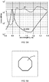
- FIG. 4B a cross-section is shown for an optical fiber with an octagonal core 40.
- the fiber core 40 has not been rotated.
- FIG. 4A the transmission loss spectra is shown for the fiber with a non-rotated octagonal core 40. Similar to the fiber example with a circular core 38 in FIG 3A , the non-rotated octagonally cored fiber experiences low transmission loss over the wide optical spectrum. An optical beam at an output of the fiber would include substantial undesirable higher order mode content. Accordingly, neither the rotation of the core nor the non-circular, non-elliptical core structure alone provides desired modal discrimination. Referring now to FIG.
- an cross-section of an optical fiber with an octagonal core 42 is shown that is similar to octagonally cored cross-section shown in FIG. 4B , except that the core structure 42 has been rotated at a pitch of 4.7 mm along the length of the fiber.
- the optical transmission loss spectra for the LP 01 mode remains very low, at approximately 0.3 dB/m or less in an operating wavelength band around 1060 nm.
- the optical transmission loss for the lowest higher order mode LP 11 is more than 20 dB/m. Other higher order modes have similar or higher loss.
- Such large higher order mode suppression can ensure the optical fiber works effectively as a single-mode fiber capable of propagating and emitting an optical beam with a very large mode area. Moreover, in many examples, such single mode operation is robust against imperfect launching condition, as well as other external perturbations.
- optical fibers of present invention glass fibers are used, while in others, silica, ZBLAN, or plastic fibers are used.
- step-index fibers have been shown for simplicity, other refractive index profiles may be used, including parabolic, multi-step, triangular, depressed, graded, etc.
- optical fibers in accordance with the present invention may be active or passive. Active fibers may include Yb-doped, Er-doped, Er-Yb-Codoped, Tm-doped, Ho-doped, Nd-doped, Bi-doped, as well as other dopants.
- Passive fibers typically include Ge-doped, Al-doped, multiple-ion-codoped, or other dopant combinations.
- optical fibers may be photosensitive. Cladding configuration for optical fibers herein may be circular as shown, or other than circular, including elliptical, polygonal, rectangular, D-shaped, flower-shaped, and irregular. Some examples of optical fibers may include single- or multiple-layer coatings, such as acrylate, silicone, polymer, carbon, metal, nanoparticles, etc., while other examples may omit coatings.
- Optical fibers in accordance with some examples of the present invention can support linear, circular, elliptical, radial, azimuthal, or combinations thereof, vortex, or complex polarization states. In some examples, rod-type fibers having short lengths and large clad sizes may be used. Also, some optical fiber examples can include longitudinally tapered fibers having varied clad or core size (or both) along the fiber axis.
- Some manufacturing methods in accordance with the present invention include sleeving the core rod preform by using an octagonal (or other preselected non-circular and non-elliptical core structure) inner hole sleeving tube. The optical fiber is then drawn slowly while spinning the preform at a predetermined or dynamically controlled rate.
- a pulsed seed source laser is operable to provide relatively low power laser pulses at a predetermined pulse width and repetition rate.
- one suitable pulse width may be 100 ps and a suitable repetition rate may be 10 MHz.
- Other seed sources may be used that are characterized by other pulse widths and repetition rates.
- one or more pre-amplification stages are used to amplify the average power of the laser pulse to a few Watts.
- One or more optical isolators are also used between stages to prevent undesirable feedback.
- a pump combiner is configured to couple pump light from one or more pump laser diodes into the cladding of a passive optical fiber, and to couple the signal light from the amplified seed source into the core of passive optical fiber.
- the passive fiber may then be spliced to an exemplary active optical fiber of the present invention.
- the passive fiber may also be an optical fiber of the present invention.
- the active fiber may have an octagonal core configuration or another core structure in accordance with the present invention.
- the active fiber has a rotated core structure with a predetermined pitch of 5 mm as described herein, and large diameter core, such as 60 ⁇ m. Other pitches and core diameters may be used.
- the active optical fiber is 3 m in length, Yb-doped, and double-clad.
- Such an optical fiber in accordance with the present invention, is configured to provide low optical transmission loss for the LP 01 mode, such as 0.2 dB/m, and high optical transmission loss for all higher order modes, such as greater than 20 dB/m, at an operating wavelength of approximately 1060 nm.
- a splice point may excite multiple modes due to mode field mismatch and large core size, higher order modes will continue to experience high transmission loss and will therefore be suppressed.
- An output optical beam is characterized by high gain and single mode propagation. Corresponding mode field diameters of output beams can exceed 50 ⁇ m, increasing the nonlinear effect threshold by about 5-fold compared to conventional large mode area fibers, which typically reach a maximum mode field diameter of 22 ⁇ m.
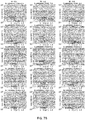
- FIGS. 7A and 7B multiple plots are shown of spectral response for different core rotation pitch and core structure.
- FIG. 7A shows a first column of five spectral response charts at different core sizes for a particular rotational pitch of 4.7 mm and a second column of five spectral response charts at different core sizes for a slightly larger rotational pitch of 5 mm.
- FIG. 7B shows three additional columns of five charts for different core sizes as listed in FIG. 7A for three larger helical pitches of 5.3 mm, 5.6 mm, and 5.9 mm.
- the optical transmission loss associated with the LP 01 mode demonstrates a sharp spectral response and is variable with respect to core size and rotational pitch.
- the optical fiber core structure and core rotation pitch can be configured to provide spectral filtering.
- Corresponding spectral filtering can be used for fiber lasers, fiber amplifiers, as well as for passive optical components.
- an optical fiber is configured to have low optical transmission loss at 1064 nm and a high optical transmission loss at 1110 nm, which is near or is approximately the stimulated Raman scattering (SRS) shifted wavelength.
- SRS stimulated Raman scattering
- an optical fiber can be configured in accordance with the present invention to provide low optical transmission loss between 1100-1480 nm, and a high loss at longer wavelength.
- the optical fiber in accordance therewith is implemented in a cascaded Raman amplifier, the spectral cutoff effect after 1480 nm will eliminate further cascaded stokes generation, and enhance output at 1480 nm.
- a Yb-doped optical fiber of the present invention can be configured to have low optical transmission loss at a laser signal wavelength, such as 1064 nm and high optical transmission loss at an amplified spontaneous emission (ASE) band, approximately between 1020-1050 nm.
- the corresponding optical fiber can then operate as an ASE filter.
- ASE noise can be significantly suppressed such that build-up of ASE will be reduced or the ASE threshold will be significantly higher.
- the optical fiber can enhance laser performance and enable further power scaling of the laser system.
- a similar technique may be applied for suppression of ASE near 1000 nm or spurious lasing in Er-Yb-codoped optical fibers, as well as for suppression of ASE near 1000 nm or spurious lasing in YB-doped fiber lasers and amplifiers operating at 976 nm.
Landscapes
- Physics & Mathematics (AREA)
- Optics & Photonics (AREA)
- Electromagnetism (AREA)
- General Physics & Mathematics (AREA)
- Engineering & Computer Science (AREA)
- Plasma & Fusion (AREA)
- Lasers (AREA)
- Investigating Or Analysing Materials By Optical Means (AREA)
Description
- Generally, the field of the present invention is optical fibers. More particularly, the present invention relates to large mode area optical fibers and single-mode operation thereof.
- It is of increasing importance for industry to keep pace with the progress of small-scale technology. With the ability to process a variety of materials and at small-scales, laser systems are well suited for precision processing applications in corresponding technologies. In particular, high power fiber lasers are well-suited for such precision applications due to their compactness, efficiency, cost-effectiveness, and potential for single-mode performance, among other advantages. However, to increase the power capabilities of such systems that utilize optical fiber, various roadblocks exist. For example, in some approaches, the power scaling of fiber lasers requires large mode area fiber to provide single-mode performance, even as the core size of such fibers increases to diameters outside practical single-mode ranges, such as approximately 25 µm or less. The onset of higher order modes tends to significantly deteriorate the beam quality of the output beam from the fiber, resulting in less than optimal performance and limiting output power scaling. Various approaches that have been developed to push the power barrier have met with mixed results, remain under development, or are very expensive. Accordingly, there remains a need for fiber laser systems capable of scaling to higher powers. Document
US-2003/0118266 discloses a optical fiber with an elliptical core, said fiber as a whole being twisted. DocumentWO 2010/056253 discloses a optical fiber with a non-elliptical core, said fiber as a whole being twisted.Both do not disclose a twisted core fiber. - In order to scale fiber laser systems to higher powers, novel optical fibers have been designed, and are disclosed herein, which allow the use of large core large mode area fibers in fiber laser systems that remain capable of single mode operation or that otherwise provide substantial suppression of higher order modes, as defined in
claim 1 and subsequent claims. In particular, a novel optical fiber includes a non-circular and non-elliptical central core structure that is rotated about an axis thereof. The non-circular and non-elliptical core structure breaks the rotational symmetry of conventional optical fibers, and provides the possibility of modal discrimination while the rotation of the core about the axis of the fiber provides modal scrambling and coupling. The combination of the two produce modal discrimination as the core size, and corresponding beam power, is scaled outside the single mode regime. For optical fibers herein having different large core sizes, particular rotational periods can be varied and selected for which the fundamental mode of the optical fiber has low transmission loss at the operating wavelength band, and the higher order modes of the fiber have high transmission loss. In this way, higher order modes can be effectively suppressed when propagating along the fiber and the fundamental mode will remain unchanged or substantially less affected. Consequently, such a fiber will have a large mode area, and at the same time, continue to provide stable single-mode operation. Optical fibers herein can be manufactured by providing a preform having a non-circular and non-elliptical core cross-section, and then drawing such preforms at predetermined spin rates corresponding to desired modal discrimination performance. - According to other aspects of the present invention, fiber lasers and fiber amplifiers are provided which are capable of being scaled to very high powers while maintaining single-mode operation. In accordance with still further aspects, spectral filters are provided which can enable further power scaling of fiber lasers and fiber amplifiers and can provide additional benefits to cascaded Raman amplifiers.
- The foregoing and other objects, features, and advantages will become more apparent from the following detailed description, which proceeds with reference to the accompanying figures, which are not necessarily to scale.
-
-
FIG. 1 is a perspective view of a section of optical fiber in accordance with an aspect of the present invention. -
FIG. 2A is a cross-sectional view of the optical fiber shown inFIG. 1 . -
FIG. 2B-2F show additional cross-sectional views of optical fibers in accordance with other aspects of the present invention. -
FIG. 3A is plot of optical transmission loss spectra. -
FIG. 3B is a cross-sectional view showing a fiber in accordance with the optical transmission loss spectra shown inFIG. 3A . -
FIG. 4A is plot of optical transmission loss spectra. -
FIG. 4B is a cross-sectional view showing a fiber in accordance with the optical transmission loss spectra shown inFIG. 4A . -
FIG. 5A is plot of optical transmission loss spectra in accordance with an optical fiber in accordance with an aspect of the present invention. -
FIG. 5B is a cross-sectional view showing a fiber in accordance with the optical transmission loss spectra shown inFIG. 5A . - FIG. 6 is a schematic of a fiber amplifier system in accordance with an aspect of the present invention.
-
FIG. 7A shows several plots of optical transmission loss spectra for various optical fiber configuration in accordance with an aspect of the present invention. -
FIG. 7B shows several additional plots associated withFIG. 7A and extending to the right thereof, in accordance with an aspect of the present invention. -
FIG. 8 is a chart schematic depicting performance of a cascaded Raman amplifier in accordance with an aspect of the present invention. - Referring now to
FIGS. 1 and2A , anoptical fiber 10 is shown in accordance with an aspect of the present invention. Theoptical fiber 10 includes acentral core 12 disposed substantially aligned with a centrallongitudinal axis 14 of thefiber 12. Around thecentral core 12 is acladding 16. Thecore 12 has a non-circular and non-elliptical geometry, which in one aspect, as shown, has anoctagonal configuration 18. Other geometries are possible, as will be discussed later. Thecladding 16 surrounding thecore 12 has a circular outer diameter geometry, though other structures are possible and in many cases preferred. As shown, theoptical fiber 10 is a double-clad optical fiber, particularly suited for fiber laser systems. Other types of configurations are possible, such as triple-clad fiber configurations, and some elements are omitted for simplicity, such as a sleeve or coating surrounding thecladding 16. Thecore 12 of theoptical fiber 10 may be active or passive, depending on the particular application or use. In typical examples, thecore 12 is large in diameter as compared to conventional optical fibers, such as greater than 20 µm, 50 µm, 80 µm, or even 100 µm. - The
central core 12 of theoptical fiber 10 is preferably a large mode area core which could support higher order modes than the fundamental mode of a propagating beam. However, theoptical fiber 10 has been fabricated in such a way that the core structure is not static along thelongitudinal axis 14 of thefiber 10. In preferred examples the cross-section structure rotates azimuthally about thelongitudinal axis 14 along the length of theoptical fiber 10 at a predetermined frequency to form a rotatedstructure 20. The rotatedstructure 20 in constant rotation embodiments is characterized by a pitch, or period, optimized for modal discrimination. For example, as shown inFIG. 1 , approximately one pitch length of rotatedcore structure 20 is shown foroptical fiber 10. The pitch length can be varied in accordance with the present invention and for different effects. For example, a constant rotated core pitch can continuously or step-wise increase or decrease in a slow or rapid fashion. Moreover, different pitch frequencies can be combined to form a core structure that is rotated in an uneven way. - Referring now to
FIGS. 2B-2F , various cross-sectional geometries are shown consistent with additional aspects of the present invention. In general, various shapes are possible and within the spirit and scope of the present invention. Polygonal shapes may be preferred for ease of manufacture. InFIG. 2B , a cross-section of an optical fiber is shown where acore 22 thereof has an octagonally starred configuration. Other polygons can include squares, rectangles, pentagons, hexagons, etc. InFIG. 2C , a cross-section of an optical fiber is shown where acore 24 thereof has asmall notch 26 along the circumference of thecore 24. InFIG. 2D , a cross-section of an optical fiber is shown where acore 28 includes one or more core protrusion features 30 at selected positions along the circumference of thecore 28. InFIG. 2E , a cross-section of an optical fiber is shown where acore 32 includes a random or asymmetric configuration of features about the circumference of thecore 32. InFIG. 2F , a cross-section of an optical fiber is shown where acore 34 includes core protrusion features 36 symmetrically disposed about the circumference of thecore 34. For different cross-sectional geometries, optical modes may evolve and interact differently therein, and beam propagation simulations can be utilized to optimize rotational pitch of the core for desired modal discrimination effects. - For example, now referring to
FIGS. 3-5 , a fiber design is shown in three different simulations. In each simulation the edge-to-edge size (or diameter) of the core is 56 µm, substantially larger than the single-mode regime of ordinary step-index fibers propagating optical fluxes at 1064 nm. Core numerical aperture as shown is 0.068 and the core is passively doped with Germanium.FIG. 3B shows a cross-section of a conventional fiber with acircular core 38.FIG. 3A shows transmission loss spectra for the same conventional circular core fiber that has been rotated about the longitudinal axis of the fiber at a pitch of 4.7 mm. Generally, rotational pitch does not substantially affect or change the propagation of optical modes therethrough given the azimuthal symmetry incircular cores 38. Accordingly, both the fundamental LP01 mode and the next higher order mode LP11, which also represents other higher order modes as well, indicate low transmission loss over a wide optical spectrum at 0.146 and 0.0346 respectively. An optical beam at an output of the fiber would include substantial undesirable higher order mode content. - In
FIG. 4B a cross-section is shown for an optical fiber with anoctagonal core 40. In this example, thefiber core 40 has not been rotated. Referring then toFIG. 4A , the transmission loss spectra is shown for the fiber with a non-rotatedoctagonal core 40. Similar to the fiber example with acircular core 38 inFIG 3A , the non-rotated octagonally cored fiber experiences low transmission loss over the wide optical spectrum. An optical beam at an output of the fiber would include substantial undesirable higher order mode content. Accordingly, neither the rotation of the core nor the non-circular, non-elliptical core structure alone provides desired modal discrimination. Referring now toFIG. 5B , an cross-section of an optical fiber with anoctagonal core 42 is shown that is similar to octagonally cored cross-section shown inFIG. 4B , except that thecore structure 42 has been rotated at a pitch of 4.7 mm along the length of the fiber. As shown inFIG. 5A , the optical transmission loss spectra for the LP01 mode remains very low, at approximately 0.3 dB/m or less in an operating wavelength band around 1060 nm. Also shown inFIG. 5A , the optical transmission loss for the lowest higher order mode LP11 is more than 20 dB/m. Other higher order modes have similar or higher loss. Such large higher order mode suppression can ensure the optical fiber works effectively as a single-mode fiber capable of propagating and emitting an optical beam with a very large mode area. Moreover, in many examples, such single mode operation is robust against imperfect launching condition, as well as other external perturbations. - In some examples of optical fibers of present invention, glass fibers are used, while in others, silica, ZBLAN, or plastic fibers are used. Moreover, while step-index fibers have been shown for simplicity, other refractive index profiles may be used, including parabolic, multi-step, triangular, depressed, graded, etc. As mentioned hereinbefore, optical fibers in accordance with the present invention may be active or passive. Active fibers may include Yb-doped, Er-doped, Er-Yb-Codoped, Tm-doped, Ho-doped, Nd-doped, Bi-doped, as well as other dopants. Passive fibers typically include Ge-doped, Al-doped, multiple-ion-codoped, or other dopant combinations. In some embodiments optical fibers may be photosensitive. Cladding configuration for optical fibers herein may be circular as shown, or other than circular, including elliptical, polygonal, rectangular, D-shaped, flower-shaped, and irregular. Some examples of optical fibers may include single- or multiple-layer coatings, such as acrylate, silicone, polymer, carbon, metal, nanoparticles, etc., while other examples may omit coatings. Optical fibers in accordance with some examples of the present invention can support linear, circular, elliptical, radial, azimuthal, or combinations thereof, vortex, or complex polarization states. In some examples, rod-type fibers having short lengths and large clad sizes may be used. Also, some optical fiber examples can include longitudinally tapered fibers having varied clad or core size (or both) along the fiber axis.
- Some manufacturing methods in accordance with the present invention include sleeving the core rod preform by using an octagonal (or other preselected non-circular and non-elliptical core structure) inner hole sleeving tube. The optical fiber is then drawn slowly while spinning the preform at a predetermined or dynamically controlled rate.
- Different examples of optical fiber in accordance with the present invention can be useful for many types of fiber laser and fiber amplifier systems. Such systems will tend to benefit significantly from the novel fiber herein, particularly with respect to beam quality, pointing stability, nonlinear effects, and material damage threshold. One example of a fiber laser system in accordance with the present invention which utilizes the fiber described herein is shown in FIG. 6 and is generally designated 44. A pulsed seed source laser is operable to provide relatively low power laser pulses at a predetermined pulse width and repetition rate. For example, one suitable pulse width may be 100 ps and a suitable repetition rate may be 10 MHz. Other seed sources may be used that are characterized by other pulse widths and repetition rates. In typical examples, one or more pre-amplification stages are used to amplify the average power of the laser pulse to a few Watts. One or more optical isolators are also used between stages to prevent undesirable feedback.
- A pump combiner is configured to couple pump light from one or more pump laser diodes into the cladding of a passive optical fiber, and to couple the signal light from the amplified seed source into the core of passive optical fiber. The passive fiber may then be spliced to an exemplary active optical fiber of the present invention. Alternatively, the passive fiber may also be an optical fiber of the present invention. The active fiber may have an octagonal core configuration or another core structure in accordance with the present invention. The active fiber has a rotated core structure with a predetermined pitch of 5 mm as described herein, and large diameter core, such as 60 µm. Other pitches and core diameters may be used.
- In a preferred example, the active optical fiber is 3 m in length, Yb-doped, and double-clad. Such an optical fiber, in accordance with the present invention, is configured to provide low optical transmission loss for the LP01 mode, such as 0.2 dB/m, and high optical transmission loss for all higher order modes, such as greater than 20 dB/m, at an operating wavelength of approximately 1060 nm. In examples where a splice point may excite multiple modes due to mode field mismatch and large core size, higher order modes will continue to experience high transmission loss and will therefore be suppressed. An output optical beam is characterized by high gain and single mode propagation. Corresponding mode field diameters of output beams can exceed 50 µm, increasing the nonlinear effect threshold by about 5-fold compared to conventional large mode area fibers, which typically reach a maximum mode field diameter of 22 µm.
- Some optical fiber examples of the present invention may be used for spectral filtering. In reference to
FIGS. 7A and7B , multiple plots are shown of spectral response for different core rotation pitch and core structure.FIG. 7A shows a first column of five spectral response charts at different core sizes for a particular rotational pitch of 4.7 mm and a second column of five spectral response charts at different core sizes for a slightly larger rotational pitch of 5 mm.FIG. 7B shows three additional columns of five charts for different core sizes as listed inFIG. 7A for three larger helical pitches of 5.3 mm, 5.6 mm, and 5.9 mm. The optical transmission loss associated with the LP01 mode demonstrates a sharp spectral response and is variable with respect to core size and rotational pitch. Accordingly, the optical fiber core structure and core rotation pitch can be configured to provide spectral filtering. Corresponding spectral filtering can be used for fiber lasers, fiber amplifiers, as well as for passive optical components. - In one application of spectral filtering in accordance with the present invention, an optical fiber is configured to have low optical transmission loss at 1064 nm and a high optical transmission loss at 1110 nm, which is near or is approximately the stimulated Raman scattering (SRS) shifted wavelength. As implemented in a fiber laser or fiber amplifier operating at high power, the SRS effect will be significantly suppressed, and the power scaling limitation due to SRS can be overcome.
- In another example, and now with reference to
FIG. 8 , an optical fiber can be configured in accordance with the present invention to provide low optical transmission loss between 1100-1480 nm, and a high loss at longer wavelength. When the optical fiber in accordance therewith is implemented in a cascaded Raman amplifier, the spectral cutoff effect after 1480 nm will eliminate further cascaded stokes generation, and enhance output at 1480 nm. - In another example, a Yb-doped optical fiber of the present invention can be configured to have low optical transmission loss at a laser signal wavelength, such as 1064 nm and high optical transmission loss at an amplified spontaneous emission (ASE) band, approximately between 1020-1050 nm. The corresponding optical fiber can then operate as an ASE filter. By implementing such an optical fiber in a fiber laser or fiber amplifier, ASE noise can be significantly suppressed such that build-up of ASE will be reduced or the ASE threshold will be significantly higher. By mitigating ASE, the optical fiber can enhance laser performance and enable further power scaling of the laser system. A similar technique may be applied for suppression of ASE near 1000 nm or spurious lasing in Er-Yb-codoped optical fibers, as well as for suppression of ASE near 1000 nm or spurious lasing in YB-doped fiber lasers and amplifiers operating at 976 nm.
- It is thought that the present invention and many of the attendant advantages thereof will be understood from the foregoing description and it will be apparent that various changes may be made in the parts thereof without departing from the scope of the invention or sacrificing all of its material advantages, the forms hereinbefore described being merely exemplary embodiments thereof.
Claims (15)
- An optical fiber, comprising:a central core, said central core having a non-circular and non-elliptical cross-section, said central core rotated about a central axis thereof along the length of the optical fiber, and a cladding disposed about said central core.
- The optical fiber of claim 1 wherein said central core has an effective diameter of larger than 50 µm.
- The optical fiber of claim 1 wherein said central core cross-section is polygonal.
- The optical fiber of claim 1 wherein the rotation of said central core about said central axis discriminate against modes higher than the fundamental mode.
- The optical fiber of claim 1 wherein said fiber is a double-clad fiber or a triple clad fiber.
- The optical fiber of claim 1 wherein said central core is doped with one or more active fiber dopants.
- The optical fiber of claim 1 wherein said fiber includes fiber parameters, including a rotational pitch and an central core geometry, that are selected so as to providespectral filtering at selected wavelengths.
- The optical fiber of claim 1 wherein said fiber provides spectral filtering through selection of fiber parameters including rotational pitch and central core geometry.
- The optical fiber of claim 1 wherein said fiber is configured to provide a spectral cutoff effect for a cascaded Raman amplifier.
- An optical system, comprising:a seed optical source configured to provide a seed beam; andan optical amplifier configured to receive and amplify the seed beam, said optical amplifier including an active optical fiber according to claim 1.
- The optical system of claim 10 wherein an output beam is produced that is substantially in the fundamental mode.
- The optical system of claim 1 or 10 wherein said central core provides modal discrimination.
- The optical system of claim 1 or 10 wherein a period of rotation of said central core is selected to maximize modal discrimination.
- The optical system of claim 1 or 10 wherein said central core has an effective diameter of larger than 25 µm.
- The optical system of claim 10 wherein said rotated core has an octagonal cross-section.
Priority Applications (1)
| Application Number | Priority Date | Filing Date | Title |
|---|---|---|---|
| SI201430605T SI2972528T1 (en) | 2013-03-15 | 2014-03-17 | Spun non-circular and non-elliptical fibers and apparatuses utilizing the same |
Applications Claiming Priority (2)
| Application Number | Priority Date | Filing Date | Title |
|---|---|---|---|
| US201361800970P | 2013-03-15 | 2013-03-15 | |
| PCT/US2014/030698 WO2014145862A2 (en) | 2013-03-15 | 2014-03-17 | Spun non-circular and non-elliptical fibers and apparatuses utilizing the same |
Publications (3)
| Publication Number | Publication Date |
|---|---|
| EP2972528A2 EP2972528A2 (en) | 2016-01-20 |
| EP2972528A4 EP2972528A4 (en) | 2016-10-12 |
| EP2972528B1 true EP2972528B1 (en) | 2017-11-22 |
Family
ID=51526012
Family Applications (1)
| Application Number | Title | Priority Date | Filing Date |
|---|---|---|---|
| EP14764000.7A Not-in-force EP2972528B1 (en) | 2013-03-15 | 2014-03-17 | Spun non-circular and non-elliptical fibers and apparatuses utilizing the same |
Country Status (6)
| Country | Link |
|---|---|
| US (1) | US9217825B2 (en) |
| EP (1) | EP2972528B1 (en) |
| CN (1) | CN105431754B (en) |
| DK (1) | DK2972528T3 (en) |
| SI (1) | SI2972528T1 (en) |
| WO (1) | WO2014145862A2 (en) |
Families Citing this family (195)
| Publication number | Priority date | Publication date | Assignee | Title |
|---|---|---|---|---|
| US9290008B1 (en) | 2011-09-20 | 2016-03-22 | Nlight Photonics Corporation | Laser marking method and system |
| US10009065B2 (en) | 2012-12-05 | 2018-06-26 | At&T Intellectual Property I, L.P. | Backhaul link for distributed antenna system |
| US9113347B2 (en) | 2012-12-05 | 2015-08-18 | At&T Intellectual Property I, Lp | Backhaul link for distributed antenna system |
| US10226837B2 (en) | 2013-03-15 | 2019-03-12 | Nlight, Inc. | Thermal processing with line beams |
| US9525524B2 (en) | 2013-05-31 | 2016-12-20 | At&T Intellectual Property I, L.P. | Remote distributed antenna system |
| US9999038B2 (en) | 2013-05-31 | 2018-06-12 | At&T Intellectual Property I, L.P. | Remote distributed antenna system |
| US8897697B1 (en) | 2013-11-06 | 2014-11-25 | At&T Intellectual Property I, Lp | Millimeter-wave surface-wave communications |
| US9209902B2 (en) | 2013-12-10 | 2015-12-08 | At&T Intellectual Property I, L.P. | Quasi-optical coupler |
| US9784913B2 (en) * | 2014-01-30 | 2017-10-10 | Nlight, Inc. | Spun round core fiber |
| US10069271B2 (en) | 2014-06-02 | 2018-09-04 | Nlight, Inc. | Scalable high power fiber laser |
| US10310201B2 (en) | 2014-08-01 | 2019-06-04 | Nlight, Inc. | Back-reflection protection and monitoring in fiber and fiber-delivered lasers |
| US9692101B2 (en) | 2014-08-26 | 2017-06-27 | At&T Intellectual Property I, L.P. | Guided wave couplers for coupling electromagnetic waves between a waveguide surface and a surface of a wire |
| US9768833B2 (en) | 2014-09-15 | 2017-09-19 | At&T Intellectual Property I, L.P. | Method and apparatus for sensing a condition in a transmission medium of electromagnetic waves |
| US10063280B2 (en) | 2014-09-17 | 2018-08-28 | At&T Intellectual Property I, L.P. | Monitoring and mitigating conditions in a communication network |
| US9628854B2 (en) | 2014-09-29 | 2017-04-18 | At&T Intellectual Property I, L.P. | Method and apparatus for distributing content in a communication network |
| US9615269B2 (en) | 2014-10-02 | 2017-04-04 | At&T Intellectual Property I, L.P. | Method and apparatus that provides fault tolerance in a communication network |
| US9685992B2 (en) | 2014-10-03 | 2017-06-20 | At&T Intellectual Property I, L.P. | Circuit panel network and methods thereof |
| US9503189B2 (en) | 2014-10-10 | 2016-11-22 | At&T Intellectual Property I, L.P. | Method and apparatus for arranging communication sessions in a communication system |
| US9762289B2 (en) | 2014-10-14 | 2017-09-12 | At&T Intellectual Property I, L.P. | Method and apparatus for transmitting or receiving signals in a transportation system |
| US9973299B2 (en) | 2014-10-14 | 2018-05-15 | At&T Intellectual Property I, L.P. | Method and apparatus for adjusting a mode of communication in a communication network |
| US9564947B2 (en) | 2014-10-21 | 2017-02-07 | At&T Intellectual Property I, L.P. | Guided-wave transmission device with diversity and methods for use therewith |
| US9627768B2 (en) | 2014-10-21 | 2017-04-18 | At&T Intellectual Property I, L.P. | Guided-wave transmission device with non-fundamental mode propagation and methods for use therewith |
| US9312919B1 (en) | 2014-10-21 | 2016-04-12 | At&T Intellectual Property I, Lp | Transmission device with impairment compensation and methods for use therewith |
| US9769020B2 (en) | 2014-10-21 | 2017-09-19 | At&T Intellectual Property I, L.P. | Method and apparatus for responding to events affecting communications in a communication network |
| US9577306B2 (en) | 2014-10-21 | 2017-02-21 | At&T Intellectual Property I, L.P. | Guided-wave transmission device and methods for use therewith |
| US9520945B2 (en) | 2014-10-21 | 2016-12-13 | At&T Intellectual Property I, L.P. | Apparatus for providing communication services and methods thereof |
| US9653770B2 (en) | 2014-10-21 | 2017-05-16 | At&T Intellectual Property I, L.P. | Guided wave coupler, coupling module and methods for use therewith |
| US9780834B2 (en) | 2014-10-21 | 2017-10-03 | At&T Intellectual Property I, L.P. | Method and apparatus for transmitting electromagnetic waves |
| US9742462B2 (en) | 2014-12-04 | 2017-08-22 | At&T Intellectual Property I, L.P. | Transmission medium and communication interfaces and methods for use therewith |
| US10243784B2 (en) | 2014-11-20 | 2019-03-26 | At&T Intellectual Property I, L.P. | System for generating topology information and methods thereof |
| US10340573B2 (en) | 2016-10-26 | 2019-07-02 | At&T Intellectual Property I, L.P. | Launcher with cylindrical coupling device and methods for use therewith |
| US9654173B2 (en) | 2014-11-20 | 2017-05-16 | At&T Intellectual Property I, L.P. | Apparatus for powering a communication device and methods thereof |
| US9800327B2 (en) | 2014-11-20 | 2017-10-24 | At&T Intellectual Property I, L.P. | Apparatus for controlling operations of a communication device and methods thereof |
| US9954287B2 (en) | 2014-11-20 | 2018-04-24 | At&T Intellectual Property I, L.P. | Apparatus for converting wireless signals and electromagnetic waves and methods thereof |
| US9680670B2 (en) | 2014-11-20 | 2017-06-13 | At&T Intellectual Property I, L.P. | Transmission device with channel equalization and control and methods for use therewith |
| US9544006B2 (en) | 2014-11-20 | 2017-01-10 | At&T Intellectual Property I, L.P. | Transmission device with mode division multiplexing and methods for use therewith |
| US9997819B2 (en) | 2015-06-09 | 2018-06-12 | At&T Intellectual Property I, L.P. | Transmission medium and method for facilitating propagation of electromagnetic waves via a core |
| US10009067B2 (en) | 2014-12-04 | 2018-06-26 | At&T Intellectual Property I, L.P. | Method and apparatus for configuring a communication interface |
| US9461706B1 (en) | 2015-07-31 | 2016-10-04 | At&T Intellectual Property I, Lp | Method and apparatus for exchanging communication signals |
| US9837783B2 (en) | 2015-01-26 | 2017-12-05 | Nlight, Inc. | High-power, single-mode fiber sources |
| US10144036B2 (en) | 2015-01-30 | 2018-12-04 | At&T Intellectual Property I, L.P. | Method and apparatus for mitigating interference affecting a propagation of electromagnetic waves guided by a transmission medium |
| CZ201572A3 (en) * | 2015-02-05 | 2016-04-20 | Ăšstav fotoniky a elektroniky AV ÄŚR, v. v. i. | Amplification module, process of its production and cladding-pumped optical device comprising thereof |
| US9876570B2 (en) | 2015-02-20 | 2018-01-23 | At&T Intellectual Property I, Lp | Guided-wave transmission device with non-fundamental mode propagation and methods for use therewith |
| US9749013B2 (en) | 2015-03-17 | 2017-08-29 | At&T Intellectual Property I, L.P. | Method and apparatus for reducing attenuation of electromagnetic waves guided by a transmission medium |
| US10050404B2 (en) | 2015-03-26 | 2018-08-14 | Nlight, Inc. | Fiber source with cascaded gain stages and/or multimode delivery fiber with low splice loss |
| CN104777552B (en) * | 2015-04-02 | 2018-01-02 | 武汉邮电科学研究院 | A kind of double-cladding active optical fiber and its manufacture method |
| US9846276B2 (en) * | 2015-04-14 | 2017-12-19 | Washington State University | Low-cost fiber optic sensor for large strains |
| US9705561B2 (en) | 2015-04-24 | 2017-07-11 | At&T Intellectual Property I, L.P. | Directional coupling device and methods for use therewith |
| US10224981B2 (en) | 2015-04-24 | 2019-03-05 | At&T Intellectual Property I, Lp | Passive electrical coupling device and methods for use therewith |
| US9793954B2 (en) | 2015-04-28 | 2017-10-17 | At&T Intellectual Property I, L.P. | Magnetic coupling device and methods for use therewith |
| US9948354B2 (en) | 2015-04-28 | 2018-04-17 | At&T Intellectual Property I, L.P. | Magnetic coupling device with reflective plate and methods for use therewith |
| CN104865633B (en) * | 2015-05-08 | 2018-01-19 | 中国科学院西安光学精密机械研究所 | Microstructure zigzag hollow core fiber |
| US9748626B2 (en) | 2015-05-14 | 2017-08-29 | At&T Intellectual Property I, L.P. | Plurality of cables having different cross-sectional shapes which are bundled together to form a transmission medium |
| US9490869B1 (en) | 2015-05-14 | 2016-11-08 | At&T Intellectual Property I, L.P. | Transmission medium having multiple cores and methods for use therewith |
| US9871282B2 (en) | 2015-05-14 | 2018-01-16 | At&T Intellectual Property I, L.P. | At least one transmission medium having a dielectric surface that is covered at least in part by a second dielectric |
| US10679767B2 (en) | 2015-05-15 | 2020-06-09 | At&T Intellectual Property I, L.P. | Transmission medium having a conductive material and methods for use therewith |
| US10650940B2 (en) | 2015-05-15 | 2020-05-12 | At&T Intellectual Property I, L.P. | Transmission medium having a conductive material and methods for use therewith |
| US9917341B2 (en) | 2015-05-27 | 2018-03-13 | At&T Intellectual Property I, L.P. | Apparatus and method for launching electromagnetic waves and for modifying radial dimensions of the propagating electromagnetic waves |
| US10154493B2 (en) | 2015-06-03 | 2018-12-11 | At&T Intellectual Property I, L.P. | Network termination and methods for use therewith |
| US10103801B2 (en) | 2015-06-03 | 2018-10-16 | At&T Intellectual Property I, L.P. | Host node device and methods for use therewith |
| US10348391B2 (en) | 2015-06-03 | 2019-07-09 | At&T Intellectual Property I, L.P. | Client node device with frequency conversion and methods for use therewith |
| US9866309B2 (en) | 2015-06-03 | 2018-01-09 | At&T Intellectual Property I, Lp | Host node device and methods for use therewith |
| US9912381B2 (en) | 2015-06-03 | 2018-03-06 | At&T Intellectual Property I, Lp | Network termination and methods for use therewith |
| US10812174B2 (en) | 2015-06-03 | 2020-10-20 | At&T Intellectual Property I, L.P. | Client node device and methods for use therewith |
| US9913139B2 (en) | 2015-06-09 | 2018-03-06 | At&T Intellectual Property I, L.P. | Signal fingerprinting for authentication of communicating devices |
| US9608692B2 (en) | 2015-06-11 | 2017-03-28 | At&T Intellectual Property I, L.P. | Repeater and methods for use therewith |
| US10142086B2 (en) | 2015-06-11 | 2018-11-27 | At&T Intellectual Property I, L.P. | Repeater and methods for use therewith |
| US9820146B2 (en) | 2015-06-12 | 2017-11-14 | At&T Intellectual Property I, L.P. | Method and apparatus for authentication and identity management of communicating devices |
| US9667317B2 (en) | 2015-06-15 | 2017-05-30 | At&T Intellectual Property I, L.P. | Method and apparatus for providing security using network traffic adjustments |
| US9640850B2 (en) | 2015-06-25 | 2017-05-02 | At&T Intellectual Property I, L.P. | Methods and apparatus for inducing a non-fundamental wave mode on a transmission medium |
| US9865911B2 (en) | 2015-06-25 | 2018-01-09 | At&T Intellectual Property I, L.P. | Waveguide system for slot radiating first electromagnetic waves that are combined into a non-fundamental wave mode second electromagnetic wave on a transmission medium |
| US9509415B1 (en) | 2015-06-25 | 2016-11-29 | At&T Intellectual Property I, L.P. | Methods and apparatus for inducing a fundamental wave mode on a transmission medium |
| WO2017008022A1 (en) | 2015-07-08 | 2017-01-12 | Nlight, Inc. | Fiber with depressed central index for increased beam parameter product |
| US10205655B2 (en) | 2015-07-14 | 2019-02-12 | At&T Intellectual Property I, L.P. | Apparatus and methods for communicating utilizing an antenna array and multiple communication paths |
| US9722318B2 (en) | 2015-07-14 | 2017-08-01 | At&T Intellectual Property I, L.P. | Method and apparatus for coupling an antenna to a device |
| US10033108B2 (en) | 2015-07-14 | 2018-07-24 | At&T Intellectual Property I, L.P. | Apparatus and methods for generating an electromagnetic wave having a wave mode that mitigates interference |
| US10341142B2 (en) | 2015-07-14 | 2019-07-02 | At&T Intellectual Property I, L.P. | Apparatus and methods for generating non-interfering electromagnetic waves on an uninsulated conductor |
| US9882257B2 (en) | 2015-07-14 | 2018-01-30 | At&T Intellectual Property I, L.P. | Method and apparatus for launching a wave mode that mitigates interference |
| US9836957B2 (en) | 2015-07-14 | 2017-12-05 | At&T Intellectual Property I, L.P. | Method and apparatus for communicating with premises equipment |
| US10148016B2 (en) | 2015-07-14 | 2018-12-04 | At&T Intellectual Property I, L.P. | Apparatus and methods for communicating utilizing an antenna array |
| US10044409B2 (en) | 2015-07-14 | 2018-08-07 | At&T Intellectual Property I, L.P. | Transmission medium and methods for use therewith |
| US9847566B2 (en) | 2015-07-14 | 2017-12-19 | At&T Intellectual Property I, L.P. | Method and apparatus for adjusting a field of a signal to mitigate interference |
| US10170840B2 (en) | 2015-07-14 | 2019-01-01 | At&T Intellectual Property I, L.P. | Apparatus and methods for sending or receiving electromagnetic signals |
| US10320586B2 (en) | 2015-07-14 | 2019-06-11 | At&T Intellectual Property I, L.P. | Apparatus and methods for generating non-interfering electromagnetic waves on an insulated transmission medium |
| US9628116B2 (en) | 2015-07-14 | 2017-04-18 | At&T Intellectual Property I, L.P. | Apparatus and methods for transmitting wireless signals |
| US9853342B2 (en) | 2015-07-14 | 2017-12-26 | At&T Intellectual Property I, L.P. | Dielectric transmission medium connector and methods for use therewith |
| US10033107B2 (en) | 2015-07-14 | 2018-07-24 | At&T Intellectual Property I, L.P. | Method and apparatus for coupling an antenna to a device |
| US9608740B2 (en) | 2015-07-15 | 2017-03-28 | At&T Intellectual Property I, L.P. | Method and apparatus for launching a wave mode that mitigates interference |
| US10090606B2 (en) | 2015-07-15 | 2018-10-02 | At&T Intellectual Property I, L.P. | Antenna system with dielectric array and methods for use therewith |
| US9793951B2 (en) | 2015-07-15 | 2017-10-17 | At&T Intellectual Property I, L.P. | Method and apparatus for launching a wave mode that mitigates interference |
| US9749053B2 (en) | 2015-07-23 | 2017-08-29 | At&T Intellectual Property I, L.P. | Node device, repeater and methods for use therewith |
| US9871283B2 (en) | 2015-07-23 | 2018-01-16 | At&T Intellectual Property I, Lp | Transmission medium having a dielectric core comprised of plural members connected by a ball and socket configuration |
| US9948333B2 (en) | 2015-07-23 | 2018-04-17 | At&T Intellectual Property I, L.P. | Method and apparatus for wireless communications to mitigate interference |
| US9912027B2 (en) | 2015-07-23 | 2018-03-06 | At&T Intellectual Property I, L.P. | Method and apparatus for exchanging communication signals |
| US10784670B2 (en) | 2015-07-23 | 2020-09-22 | At&T Intellectual Property I, L.P. | Antenna support for aligning an antenna |
| US9735833B2 (en) | 2015-07-31 | 2017-08-15 | At&T Intellectual Property I, L.P. | Method and apparatus for communications management in a neighborhood network |
| US9967173B2 (en) | 2015-07-31 | 2018-05-08 | At&T Intellectual Property I, L.P. | Method and apparatus for authentication and identity management of communicating devices |
| US10020587B2 (en) | 2015-07-31 | 2018-07-10 | At&T Intellectual Property I, L.P. | Radial antenna and methods for use therewith |
| US9904535B2 (en) | 2015-09-14 | 2018-02-27 | At&T Intellectual Property I, L.P. | Method and apparatus for distributing software |
| US9705571B2 (en) | 2015-09-16 | 2017-07-11 | At&T Intellectual Property I, L.P. | Method and apparatus for use with a radio distributed antenna system |
| US10009901B2 (en) | 2015-09-16 | 2018-06-26 | At&T Intellectual Property I, L.P. | Method, apparatus, and computer-readable storage medium for managing utilization of wireless resources between base stations |
| US10079661B2 (en) | 2015-09-16 | 2018-09-18 | At&T Intellectual Property I, L.P. | Method and apparatus for use with a radio distributed antenna system having a clock reference |
| US10136434B2 (en) | 2015-09-16 | 2018-11-20 | At&T Intellectual Property I, L.P. | Method and apparatus for use with a radio distributed antenna system having an ultra-wideband control channel |
| US10051629B2 (en) | 2015-09-16 | 2018-08-14 | At&T Intellectual Property I, L.P. | Method and apparatus for use with a radio distributed antenna system having an in-band reference signal |
| US10009063B2 (en) | 2015-09-16 | 2018-06-26 | At&T Intellectual Property I, L.P. | Method and apparatus for use with a radio distributed antenna system having an out-of-band reference signal |
| WO2017053985A1 (en) | 2015-09-24 | 2017-03-30 | Nlight, Inc. | Beam parameter product (bpp) control by varying fiber-to-fiber angle |
| US9769128B2 (en) | 2015-09-28 | 2017-09-19 | At&T Intellectual Property I, L.P. | Method and apparatus for encryption of communications over a network |
| US9729197B2 (en) | 2015-10-01 | 2017-08-08 | At&T Intellectual Property I, L.P. | Method and apparatus for communicating network management traffic over a network |
| US10074890B2 (en) | 2015-10-02 | 2018-09-11 | At&T Intellectual Property I, L.P. | Communication device and antenna with integrated light assembly |
| US9882277B2 (en) | 2015-10-02 | 2018-01-30 | At&T Intellectual Property I, Lp | Communication device and antenna assembly with actuated gimbal mount |
| US9876264B2 (en) | 2015-10-02 | 2018-01-23 | At&T Intellectual Property I, Lp | Communication system, guided wave switch and methods for use therewith |
| US10355367B2 (en) | 2015-10-16 | 2019-07-16 | At&T Intellectual Property I, L.P. | Antenna structure for exchanging wireless signals |
| US10665942B2 (en) | 2015-10-16 | 2020-05-26 | At&T Intellectual Property I, L.P. | Method and apparatus for adjusting wireless communications |
| US10051483B2 (en) | 2015-10-16 | 2018-08-14 | At&T Intellectual Property I, L.P. | Method and apparatus for directing wireless signals |
| US10434600B2 (en) | 2015-11-23 | 2019-10-08 | Nlight, Inc. | Fine-scale temporal control for laser material processing |
| US11179807B2 (en) | 2015-11-23 | 2021-11-23 | Nlight, Inc. | Fine-scale temporal control for laser material processing |
| US9917410B2 (en) * | 2015-12-04 | 2018-03-13 | Nlight, Inc. | Optical mode filter employing radially asymmetric fiber |
| US10466494B2 (en) * | 2015-12-18 | 2019-11-05 | Nlight, Inc. | Reverse interleaving for laser line generators |
| US20170189992A1 (en) * | 2015-12-31 | 2017-07-06 | Nlight, Inc. | Black sub-anodized marking using picosecond bursts |
| US9912419B1 (en) | 2016-08-24 | 2018-03-06 | At&T Intellectual Property I, L.P. | Method and apparatus for managing a fault in a distributed antenna system |
| US9860075B1 (en) | 2016-08-26 | 2018-01-02 | At&T Intellectual Property I, L.P. | Method and communication node for broadband distribution |
| US10291311B2 (en) | 2016-09-09 | 2019-05-14 | At&T Intellectual Property I, L.P. | Method and apparatus for mitigating a fault in a distributed antenna system |
| US11032819B2 (en) | 2016-09-15 | 2021-06-08 | At&T Intellectual Property I, L.P. | Method and apparatus for use with a radio distributed antenna system having a control channel reference signal |
| US10732439B2 (en) | 2016-09-29 | 2020-08-04 | Nlight, Inc. | Fiber-coupled device for varying beam characteristics |
| US10673199B2 (en) | 2016-09-29 | 2020-06-02 | Nlight, Inc. | Fiber-based saturable absorber |
| US10673198B2 (en) | 2016-09-29 | 2020-06-02 | Nlight, Inc. | Fiber-coupled laser with time varying beam characteristics |
| US10295845B2 (en) * | 2016-09-29 | 2019-05-21 | Nlight, Inc. | Adjustable beam characteristics |
| US10730785B2 (en) | 2016-09-29 | 2020-08-04 | Nlight, Inc. | Optical fiber bending mechanisms |
| US10673197B2 (en) | 2016-09-29 | 2020-06-02 | Nlight, Inc. | Fiber-based optical modulator |
| US10340600B2 (en) | 2016-10-18 | 2019-07-02 | At&T Intellectual Property I, L.P. | Apparatus and methods for launching guided waves via plural waveguide systems |
| US10135146B2 (en) | 2016-10-18 | 2018-11-20 | At&T Intellectual Property I, L.P. | Apparatus and methods for launching guided waves via circuits |
| US10135147B2 (en) | 2016-10-18 | 2018-11-20 | At&T Intellectual Property I, L.P. | Apparatus and methods for launching guided waves via an antenna |
| US9876605B1 (en) | 2016-10-21 | 2018-01-23 | At&T Intellectual Property I, L.P. | Launcher and coupling system to support desired guided wave mode |
| US10374316B2 (en) | 2016-10-21 | 2019-08-06 | At&T Intellectual Property I, L.P. | System and dielectric antenna with non-uniform dielectric |
| US10811767B2 (en) | 2016-10-21 | 2020-10-20 | At&T Intellectual Property I, L.P. | System and dielectric antenna with convex dielectric radome |
| US9991580B2 (en) | 2016-10-21 | 2018-06-05 | At&T Intellectual Property I, L.P. | Launcher and coupling system for guided wave mode cancellation |
| US10312567B2 (en) | 2016-10-26 | 2019-06-04 | At&T Intellectual Property I, L.P. | Launcher with planar strip antenna and methods for use therewith |
| US10498044B2 (en) | 2016-11-03 | 2019-12-03 | At&T Intellectual Property I, L.P. | Apparatus for configuring a surface of an antenna |
| US10225025B2 (en) | 2016-11-03 | 2019-03-05 | At&T Intellectual Property I, L.P. | Method and apparatus for detecting a fault in a communication system |
| US10291334B2 (en) | 2016-11-03 | 2019-05-14 | At&T Intellectual Property I, L.P. | System for detecting a fault in a communication system |
| US10224634B2 (en) | 2016-11-03 | 2019-03-05 | At&T Intellectual Property I, L.P. | Methods and apparatus for adjusting an operational characteristic of an antenna |
| US11347069B2 (en) | 2016-11-22 | 2022-05-31 | Lumentum Operations Llc | Rotary optical beam generator |
| US10429584B2 (en) * | 2016-11-22 | 2019-10-01 | Lumentum Operations Llc | Rotary optical beam generator |
| US10340603B2 (en) | 2016-11-23 | 2019-07-02 | At&T Intellectual Property I, L.P. | Antenna system having shielded structural configurations for assembly |
| US10535928B2 (en) | 2016-11-23 | 2020-01-14 | At&T Intellectual Property I, L.P. | Antenna system and methods for use therewith |
| US10178445B2 (en) | 2016-11-23 | 2019-01-08 | At&T Intellectual Property I, L.P. | Methods, devices, and systems for load balancing between a plurality of waveguides |
| US10340601B2 (en) | 2016-11-23 | 2019-07-02 | At&T Intellectual Property I, L.P. | Multi-antenna system and methods for use therewith |
| US10090594B2 (en) | 2016-11-23 | 2018-10-02 | At&T Intellectual Property I, L.P. | Antenna system having structural configurations for assembly |
| US10361489B2 (en) | 2016-12-01 | 2019-07-23 | At&T Intellectual Property I, L.P. | Dielectric dish antenna system and methods for use therewith |
| US10305190B2 (en) | 2016-12-01 | 2019-05-28 | At&T Intellectual Property I, L.P. | Reflecting dielectric antenna system and methods for use therewith |
| US10382976B2 (en) | 2016-12-06 | 2019-08-13 | At&T Intellectual Property I, L.P. | Method and apparatus for managing wireless communications based on communication paths and network device positions |
| US9927517B1 (en) | 2016-12-06 | 2018-03-27 | At&T Intellectual Property I, L.P. | Apparatus and methods for sensing rainfall |
| US10020844B2 (en) | 2016-12-06 | 2018-07-10 | T&T Intellectual Property I, L.P. | Method and apparatus for broadcast communication via guided waves |
| US10694379B2 (en) | 2016-12-06 | 2020-06-23 | At&T Intellectual Property I, L.P. | Waveguide system with device-based authentication and methods for use therewith |
| US10637149B2 (en) | 2016-12-06 | 2020-04-28 | At&T Intellectual Property I, L.P. | Injection molded dielectric antenna and methods for use therewith |
| US10439675B2 (en) | 2016-12-06 | 2019-10-08 | At&T Intellectual Property I, L.P. | Method and apparatus for repeating guided wave communication signals |
| US10326494B2 (en) | 2016-12-06 | 2019-06-18 | At&T Intellectual Property I, L.P. | Apparatus for measurement de-embedding and methods for use therewith |
| US10727599B2 (en) | 2016-12-06 | 2020-07-28 | At&T Intellectual Property I, L.P. | Launcher with slot antenna and methods for use therewith |
| US10819035B2 (en) | 2016-12-06 | 2020-10-27 | At&T Intellectual Property I, L.P. | Launcher with helical antenna and methods for use therewith |
| US10135145B2 (en) | 2016-12-06 | 2018-11-20 | At&T Intellectual Property I, L.P. | Apparatus and methods for generating an electromagnetic wave along a transmission medium |
| US10755542B2 (en) | 2016-12-06 | 2020-08-25 | At&T Intellectual Property I, L.P. | Method and apparatus for surveillance via guided wave communication |
| US10547348B2 (en) | 2016-12-07 | 2020-01-28 | At&T Intellectual Property I, L.P. | Method and apparatus for switching transmission mediums in a communication system |
| US10446936B2 (en) | 2016-12-07 | 2019-10-15 | At&T Intellectual Property I, L.P. | Multi-feed dielectric antenna system and methods for use therewith |
| US10027397B2 (en) | 2016-12-07 | 2018-07-17 | At&T Intellectual Property I, L.P. | Distributed antenna system and methods for use therewith |
| US10139820B2 (en) | 2016-12-07 | 2018-11-27 | At&T Intellectual Property I, L.P. | Method and apparatus for deploying equipment of a communication system |
| US9893795B1 (en) | 2016-12-07 | 2018-02-13 | At&T Intellectual Property I, Lp | Method and repeater for broadband distribution |
| US10168695B2 (en) | 2016-12-07 | 2019-01-01 | At&T Intellectual Property I, L.P. | Method and apparatus for controlling an unmanned aircraft |
| US10359749B2 (en) | 2016-12-07 | 2019-07-23 | At&T Intellectual Property I, L.P. | Method and apparatus for utilities management via guided wave communication |
| US10389029B2 (en) | 2016-12-07 | 2019-08-20 | At&T Intellectual Property I, L.P. | Multi-feed dielectric antenna system with core selection and methods for use therewith |
| US10243270B2 (en) | 2016-12-07 | 2019-03-26 | At&T Intellectual Property I, L.P. | Beam adaptive multi-feed dielectric antenna system and methods for use therewith |
| US9911020B1 (en) | 2016-12-08 | 2018-03-06 | At&T Intellectual Property I, L.P. | Method and apparatus for tracking via a radio frequency identification device |
| US10069535B2 (en) | 2016-12-08 | 2018-09-04 | At&T Intellectual Property I, L.P. | Apparatus and methods for launching electromagnetic waves having a certain electric field structure |
| US10916969B2 (en) | 2016-12-08 | 2021-02-09 | At&T Intellectual Property I, L.P. | Method and apparatus for providing power using an inductive coupling |
| US10411356B2 (en) | 2016-12-08 | 2019-09-10 | At&T Intellectual Property I, L.P. | Apparatus and methods for selectively targeting communication devices with an antenna array |
| US10777873B2 (en) | 2016-12-08 | 2020-09-15 | At&T Intellectual Property I, L.P. | Method and apparatus for mounting network devices |
| US10326689B2 (en) | 2016-12-08 | 2019-06-18 | At&T Intellectual Property I, L.P. | Method and system for providing alternative communication paths |
| US10938108B2 (en) | 2016-12-08 | 2021-03-02 | At&T Intellectual Property I, L.P. | Frequency selective multi-feed dielectric antenna system and methods for use therewith |
| US10103422B2 (en) | 2016-12-08 | 2018-10-16 | At&T Intellectual Property I, L.P. | Method and apparatus for mounting network devices |
| US9998870B1 (en) | 2016-12-08 | 2018-06-12 | At&T Intellectual Property I, L.P. | Method and apparatus for proximity sensing |
| US10601494B2 (en) | 2016-12-08 | 2020-03-24 | At&T Intellectual Property I, L.P. | Dual-band communication device and method for use therewith |
| US10530505B2 (en) | 2016-12-08 | 2020-01-07 | At&T Intellectual Property I, L.P. | Apparatus and methods for launching electromagnetic waves along a transmission medium |
| US10389037B2 (en) | 2016-12-08 | 2019-08-20 | At&T Intellectual Property I, L.P. | Apparatus and methods for selecting sections of an antenna array and use therewith |
| US10340983B2 (en) | 2016-12-09 | 2019-07-02 | At&T Intellectual Property I, L.P. | Method and apparatus for surveying remote sites via guided wave communications |
| US10264586B2 (en) | 2016-12-09 | 2019-04-16 | At&T Mobility Ii Llc | Cloud-based packet controller and methods for use therewith |
| US9838896B1 (en) | 2016-12-09 | 2017-12-05 | At&T Intellectual Property I, L.P. | Method and apparatus for assessing network coverage |
| US9973940B1 (en) | 2017-02-27 | 2018-05-15 | At&T Intellectual Property I, L.P. | Apparatus and methods for dynamic impedance matching of a guided wave launcher |
| US10298293B2 (en) | 2017-03-13 | 2019-05-21 | At&T Intellectual Property I, L.P. | Apparatus of communication utilizing wireless network devices |
| CN108333672B (en) * | 2018-01-04 | 2020-01-17 | 南京邮电大学 | A Large Mode Field Single Mode Fiber with Heterospiral Cladding Structure |
| CN110967789B (en) * | 2018-08-06 | 2022-08-02 | 朗美通经营有限责任公司 | Rotary light beam generator |
| CN109066279B (en) * | 2018-09-07 | 2024-03-26 | 华南理工大学 | All-fiber vortex optical laser based on orbital angular momentum mode resonance |
| CN111694098B (en) * | 2019-03-13 | 2022-12-27 | 朗美通经营有限责任公司 | Tapered non-concentric core optical fiber |
| CN110165531A (en) * | 2019-06-27 | 2019-08-23 | 深圳市创鑫激光股份有限公司 | A kind of large mode field triple clad passive fiber, mode stripper and optical fiber laser |
| AU2020307661B2 (en) * | 2019-06-28 | 2023-02-23 | Inphotech Spolka Z Ograniczona Odpowiedzialnoscia | Fibre-optic measurement system, method of adaptation of the communication optical fibre into a measurement system, and fibre-optic measurement and communication system |
| JP7584258B2 (en) * | 2019-09-16 | 2024-11-15 | ルーメンタム オペレーションズ エルエルシー | Rotating light beam generator |
| CN120192089A (en) * | 2025-03-06 | 2025-06-24 | 中国电子科技集团公司第四十六研究所 | A method for preparing a spiral annular core coaxial dual-waveguide type rare earth-doped optical fiber |
Family Cites Families (26)
| Publication number | Priority date | Publication date | Assignee | Title |
|---|---|---|---|---|
| US4372645A (en) | 1978-03-10 | 1983-02-08 | Bell Telephone Laboratories, Incorporated | Optical fiber with enhanced mode coupling |
| US4315666A (en) | 1979-03-19 | 1982-02-16 | Hicks Jr John W | Coupled communications fibers |
| US4555177A (en) | 1983-12-22 | 1985-11-26 | The United States Of America As Represented By The Secretary Of The Navy | Method and apparatus for detecting singlet state resonance fluorescence |
| US6427491B1 (en) * | 1999-08-20 | 2002-08-06 | Corning Incorporated | Method for making fibers having cores with non-circular cross-sections |
| US6422043B1 (en) * | 1999-11-16 | 2002-07-23 | Fitel Usa Corp. | Method of making an improved multimode optical fiber and fiber made by method |
| US6496301B1 (en) * | 2000-03-10 | 2002-12-17 | The United States Of America As Represented By The Secretary Of The Navy | Helical fiber amplifier |
| US6480637B1 (en) | 2000-09-30 | 2002-11-12 | General Photonics Corporation | Fiber squeezer polarization controller with low activation loss |
| US20030118285A1 (en) * | 2001-12-06 | 2003-06-26 | Kopp Victor Il?Apos;Ich | Customizable chirped chiral fiber bragg grating |
| CA2509038A1 (en) * | 2001-12-06 | 2003-06-19 | Chiral Photonics, Inc. | Chiral fiber sensor apparatus and method |
| JP4301822B2 (en) | 2003-01-24 | 2009-07-22 | 富士通株式会社 | Optical amplifier with polarization mode dispersion compensation function |
| US7376360B2 (en) | 2004-04-26 | 2008-05-20 | Lucent Technologies Inc. | Optical device for extracting a sideband signal from a composite signal including orthogonally modulated signals |
| US7424193B2 (en) | 2004-07-14 | 2008-09-09 | The Regents Of The University Of Michigan | Composite waveguide |
| US7167630B2 (en) * | 2004-11-08 | 2007-01-23 | Kodak Il, Ltd. | Beam shaper and imaging head having beam shapers |
| DE602005006383T2 (en) | 2005-03-04 | 2009-06-04 | Fujitsu Ltd., Kawasaki | Chiral optical fiber |
| US7787729B2 (en) * | 2005-05-20 | 2010-08-31 | Imra America, Inc. | Single mode propagation in fibers and rods with large leakage channels |
| JP4983312B2 (en) | 2007-02-28 | 2012-07-25 | 住友電気工業株式会社 | Optical transmission module and method for detecting wavelength change or degradation of emitted light |
| DK3133426T3 (en) | 2007-03-21 | 2019-10-07 | Nufern | OPTICAL FIBER ARTICLE FOR HANDLING GREATER ENERGY AND PROCEDURE FOR MANUFACTURING OR USING THEREOF |
| JP4452296B2 (en) * | 2007-08-21 | 2010-04-21 | 日立電線株式会社 | Optical waveguide type optical coupling mechanism |
| JP2009168914A (en) * | 2008-01-11 | 2009-07-30 | Mitsubishi Cable Ind Ltd | Optical fiber and method for manufacturing the same |
| JP5227038B2 (en) * | 2008-01-16 | 2013-07-03 | 三菱電線工業株式会社 | Optical fiber |
| US7817683B2 (en) | 2008-01-22 | 2010-10-19 | Nufern | Pulsed linearly polarized optical fiber laser using unpolarized Q-switched seed laser and having good output power stability |
| DK2321678T3 (en) * | 2008-08-18 | 2019-03-11 | Nkt Photonics As | Optical fiber with resonant structure of casing connected to a light receiver |
| WO2010056253A1 (en) * | 2008-11-17 | 2010-05-20 | Raytheon Company | Method and apparatus for generation and amplification of light in a semi-guiding high aspect ratio core fiber |
| EP2430714A4 (en) * | 2009-05-11 | 2013-07-03 | Ofs Fitel Llc | FILTER FIBER FOR USE IN RAMAN LASER EMISSION APPLICATIONS AND MANUFACTURING TECHNIQUES |
| EP2630528B1 (en) * | 2010-10-22 | 2023-04-05 | IPG Photonics Corporation | Fiber with asymmetrical core and method for manufacturing same |
| US8582609B2 (en) | 2011-04-01 | 2013-11-12 | Calmar Optcom, Inc. | Fiber lasers with devices capable of suppressing high-order mode mixing and generating high quality and low noise laser light |
-
2014
- 2014-03-17 EP EP14764000.7A patent/EP2972528B1/en not_active Not-in-force
- 2014-03-17 CN CN201480027215.0A patent/CN105431754B/en not_active Expired - Fee Related
- 2014-03-17 DK DK14764000.7T patent/DK2972528T3/en active
- 2014-03-17 SI SI201430605T patent/SI2972528T1/en unknown
- 2014-03-17 WO PCT/US2014/030698 patent/WO2014145862A2/en not_active Ceased
- 2014-03-18 US US14/218,738 patent/US9217825B2/en not_active Expired - Fee Related
Non-Patent Citations (1)
| Title |
|---|
| None * |
Also Published As
| Publication number | Publication date |
|---|---|
| WO2014145862A2 (en) | 2014-09-18 |
| WO2014145862A8 (en) | 2017-05-11 |
| EP2972528A2 (en) | 2016-01-20 |
| CN105431754B (en) | 2018-05-15 |
| WO2014145862A3 (en) | 2014-12-04 |
| CN105431754A (en) | 2016-03-23 |
| US20140268310A1 (en) | 2014-09-18 |
| SI2972528T1 (en) | 2018-03-30 |
| EP2972528A4 (en) | 2016-10-12 |
| US9217825B2 (en) | 2015-12-22 |
| DK2972528T3 (en) | 2018-03-05 |
Similar Documents
| Publication | Publication Date | Title |
|---|---|---|
| US9217825B2 (en) | Spun non-circular and non-elliptical core optical fibers and apparatuses utilizing the same | |
| US9158070B2 (en) | Active tapers with reduced nonlinearity | |
| US10838141B2 (en) | Spun round core fiber | |
| US6751388B2 (en) | Fiber lasers having a complex-valued Vc-parameter for gain-guiding | |
| US8731358B2 (en) | Multi-cladding fiber | |
| US7835608B2 (en) | Method and apparatus for optical delivery fiber having cladding with absorbing regions | |
| JP4443627B2 (en) | Optical fiber laser | |
| US9077148B2 (en) | Gain-equalized few-mode fiber amplifier | |
| JPWO2009028614A1 (en) | Rare earth doped core multi-clad fiber, fiber amplifier and fiber laser | |
| CN105826798A (en) | High-power, single-mode fiber sources | |
| US20150333473A1 (en) | High Power Raman-Based Fiber Laser System and Method of Operating the Same | |
| US9653871B1 (en) | Rare-earth doped gain fibers | |
| CN102439805A (en) | Filter fiber for use in raman lasing applications and techniques for manufacturing same | |
| US8611002B2 (en) | Optical fiber lasers and amplifiers and methods for providing optical gain | |
| US9225142B2 (en) | Fiber amplifier with multi section core | |
| Hotoleanu et al. | High-order modes suppression in large mode area active fibers by controlling the radial distribution of the rare earth dopant | |
| US20160282553A1 (en) | Optical fiber with mosaic fiber | |
| EP2488904B1 (en) | Optical fiber apparatus with suppression of higher order modes | |
| Schreiber et al. | High power photonic crystal fiber laser systems | |
| WO2013002787A1 (en) | High power raman-based fiber laser system and method of operating the same | |
| Marciante et al. | Mode control in large-mode-area fiber lasers via gain filtering | |
| Ustimchik et al. | Tapered double-clad optical fibers as gain medium for high power lasers and amplifiers |
Legal Events
| Date | Code | Title | Description |
|---|---|---|---|
| PUAI | Public reference made under article 153(3) epc to a published international application that has entered the european phase |
Free format text: ORIGINAL CODE: 0009012 |
|
| 17P | Request for examination filed |
Effective date: 20150925 |
|
| AK | Designated contracting states |
Kind code of ref document: A2 Designated state(s): AL AT BE BG CH CY CZ DE DK EE ES FI FR GB GR HR HU IE IS IT LI LT LU LV MC MK MT NL NO PL PT RO RS SE SI SK SM TR |
|
| AX | Request for extension of the european patent |
Extension state: BA ME |
|
| DAX | Request for extension of the european patent (deleted) | ||
| A4 | Supplementary search report drawn up and despatched |
Effective date: 20160909 |
|
| RIC1 | Information provided on ipc code assigned before grant |
Ipc: H01S 3/067 20060101ALN20160905BHEP Ipc: G02B 6/02 20060101AFI20160905BHEP |
|
| GRAP | Despatch of communication of intention to grant a patent |
Free format text: ORIGINAL CODE: EPIDOSNIGR1 |
|
| RIC1 | Information provided on ipc code assigned before grant |
Ipc: H01S 3/067 20060101ALI20170517BHEP Ipc: H01S 3/094 20060101ALN20170517BHEP Ipc: G02B 6/036 20060101ALI20170517BHEP Ipc: G02B 6/02 20060101AFI20170517BHEP Ipc: H01S 3/16 20060101ALN20170517BHEP Ipc: H01S 3/30 20060101ALI20170517BHEP Ipc: H01S 3/0941 20060101ALN20170517BHEP |
|
| RIC1 | Information provided on ipc code assigned before grant |
Ipc: H01S 3/067 20060101ALI20170522BHEP Ipc: H01S 3/30 20060101ALI20170522BHEP Ipc: G02B 6/036 20060101ALI20170522BHEP Ipc: G02B 6/02 20060101AFI20170522BHEP Ipc: H01S 3/094 20060101ALN20170522BHEP Ipc: H01S 3/0941 20060101ALN20170522BHEP Ipc: H01S 3/16 20060101ALN20170522BHEP |
|
| INTG | Intention to grant announced |
Effective date: 20170609 |
|
| GRAS | Grant fee paid |
Free format text: ORIGINAL CODE: EPIDOSNIGR3 |
|
| GRAA | (expected) grant |
Free format text: ORIGINAL CODE: 0009210 |
|
| RIN1 | Information on inventor provided before grant (corrected) |
Inventor name: KOPONEN JOONA Inventor name: SOSNOWSKI THOMAS S. Inventor name: YE, CHANGGENG |
|
| RAP1 | Party data changed (applicant data changed or rights of an application transferred) |
Owner name: NLIGHT, INC. |
|
| AK | Designated contracting states |
Kind code of ref document: B1 Designated state(s): AL AT BE BG CH CY CZ DE DK EE ES FI FR GB GR HR HU IE IS IT LI LT LU LV MC MK MT NL NO PL PT RO RS SE SI SK SM TR |
|
| REG | Reference to a national code |
Ref country code: GB Ref legal event code: FG4D |
|
| REG | Reference to a national code |
Ref country code: CH Ref legal event code: EP |
|
| REG | Reference to a national code |
Ref country code: IE Ref legal event code: FG4D |
|
| REG | Reference to a national code |
Ref country code: AT Ref legal event code: REF Ref document number: 948911 Country of ref document: AT Kind code of ref document: T Effective date: 20171215 |
|
| REG | Reference to a national code |
Ref country code: DE Ref legal event code: R096 Ref document number: 602014017628 Country of ref document: DE |
|
| REG | Reference to a national code |
Ref country code: DK Ref legal event code: T3 Effective date: 20180227 |
|
| REG | Reference to a national code |
Ref country code: NL Ref legal event code: MP Effective date: 20171122 Ref country code: FR Ref legal event code: PLFP Year of fee payment: 5 |
|
| REG | Reference to a national code |
Ref country code: LT Ref legal event code: MG4D |
|
| REG | Reference to a national code |
Ref country code: AT Ref legal event code: MK05 Ref document number: 948911 Country of ref document: AT Kind code of ref document: T Effective date: 20171122 |
|
| PG25 | Lapsed in a contracting state [announced via postgrant information from national office to epo] |
Ref country code: NL Free format text: LAPSE BECAUSE OF FAILURE TO SUBMIT A TRANSLATION OF THE DESCRIPTION OR TO PAY THE FEE WITHIN THE PRESCRIBED TIME-LIMIT Effective date: 20171122 Ref country code: LT Free format text: LAPSE BECAUSE OF FAILURE TO SUBMIT A TRANSLATION OF THE DESCRIPTION OR TO PAY THE FEE WITHIN THE PRESCRIBED TIME-LIMIT Effective date: 20171122 Ref country code: NO Free format text: LAPSE BECAUSE OF FAILURE TO SUBMIT A TRANSLATION OF THE DESCRIPTION OR TO PAY THE FEE WITHIN THE PRESCRIBED TIME-LIMIT Effective date: 20180222 Ref country code: ES Free format text: LAPSE BECAUSE OF FAILURE TO SUBMIT A TRANSLATION OF THE DESCRIPTION OR TO PAY THE FEE WITHIN THE PRESCRIBED TIME-LIMIT Effective date: 20171122 Ref country code: SE Free format text: LAPSE BECAUSE OF FAILURE TO SUBMIT A TRANSLATION OF THE DESCRIPTION OR TO PAY THE FEE WITHIN THE PRESCRIBED TIME-LIMIT Effective date: 20171122 |
|
| PG25 | Lapsed in a contracting state [announced via postgrant information from national office to epo] |
Ref country code: HR Free format text: LAPSE BECAUSE OF FAILURE TO SUBMIT A TRANSLATION OF THE DESCRIPTION OR TO PAY THE FEE WITHIN THE PRESCRIBED TIME-LIMIT Effective date: 20171122 Ref country code: AT Free format text: LAPSE BECAUSE OF FAILURE TO SUBMIT A TRANSLATION OF THE DESCRIPTION OR TO PAY THE FEE WITHIN THE PRESCRIBED TIME-LIMIT Effective date: 20171122 Ref country code: GR Free format text: LAPSE BECAUSE OF FAILURE TO SUBMIT A TRANSLATION OF THE DESCRIPTION OR TO PAY THE FEE WITHIN THE PRESCRIBED TIME-LIMIT Effective date: 20180223 Ref country code: BG Free format text: LAPSE BECAUSE OF FAILURE TO SUBMIT A TRANSLATION OF THE DESCRIPTION OR TO PAY THE FEE WITHIN THE PRESCRIBED TIME-LIMIT Effective date: 20180222 Ref country code: RS Free format text: LAPSE BECAUSE OF FAILURE TO SUBMIT A TRANSLATION OF THE DESCRIPTION OR TO PAY THE FEE WITHIN THE PRESCRIBED TIME-LIMIT Effective date: 20171122 Ref country code: LV Free format text: LAPSE BECAUSE OF FAILURE TO SUBMIT A TRANSLATION OF THE DESCRIPTION OR TO PAY THE FEE WITHIN THE PRESCRIBED TIME-LIMIT Effective date: 20171122 |
|
| PG25 | Lapsed in a contracting state [announced via postgrant information from national office to epo] |
Ref country code: SK Free format text: LAPSE BECAUSE OF FAILURE TO SUBMIT A TRANSLATION OF THE DESCRIPTION OR TO PAY THE FEE WITHIN THE PRESCRIBED TIME-LIMIT Effective date: 20171122 Ref country code: CZ Free format text: LAPSE BECAUSE OF FAILURE TO SUBMIT A TRANSLATION OF THE DESCRIPTION OR TO PAY THE FEE WITHIN THE PRESCRIBED TIME-LIMIT Effective date: 20171122 Ref country code: EE Free format text: LAPSE BECAUSE OF FAILURE TO SUBMIT A TRANSLATION OF THE DESCRIPTION OR TO PAY THE FEE WITHIN THE PRESCRIBED TIME-LIMIT Effective date: 20171122 Ref country code: CY Free format text: LAPSE BECAUSE OF FAILURE TO SUBMIT A TRANSLATION OF THE DESCRIPTION OR TO PAY THE FEE WITHIN THE PRESCRIBED TIME-LIMIT Effective date: 20171122 |
|
| REG | Reference to a national code |
Ref country code: DE Ref legal event code: R097 Ref document number: 602014017628 Country of ref document: DE |
|
| PG25 | Lapsed in a contracting state [announced via postgrant information from national office to epo] |
Ref country code: IT Free format text: LAPSE BECAUSE OF FAILURE TO SUBMIT A TRANSLATION OF THE DESCRIPTION OR TO PAY THE FEE WITHIN THE PRESCRIBED TIME-LIMIT Effective date: 20171122 Ref country code: SM Free format text: LAPSE BECAUSE OF FAILURE TO SUBMIT A TRANSLATION OF THE DESCRIPTION OR TO PAY THE FEE WITHIN THE PRESCRIBED TIME-LIMIT Effective date: 20171122 Ref country code: RO Free format text: LAPSE BECAUSE OF FAILURE TO SUBMIT A TRANSLATION OF THE DESCRIPTION OR TO PAY THE FEE WITHIN THE PRESCRIBED TIME-LIMIT Effective date: 20171122 Ref country code: PL Free format text: LAPSE BECAUSE OF FAILURE TO SUBMIT A TRANSLATION OF THE DESCRIPTION OR TO PAY THE FEE WITHIN THE PRESCRIBED TIME-LIMIT Effective date: 20171122 |
|
| PLBE | No opposition filed within time limit |
Free format text: ORIGINAL CODE: 0009261 |
|
| STAA | Information on the status of an ep patent application or granted ep patent |
Free format text: STATUS: NO OPPOSITION FILED WITHIN TIME LIMIT |
|
| 26N | No opposition filed |
Effective date: 20180823 |
|
| REG | Reference to a national code |
Ref country code: CH Ref legal event code: PL |
|
| PG25 | Lapsed in a contracting state [announced via postgrant information from national office to epo] |
Ref country code: MC Free format text: LAPSE BECAUSE OF FAILURE TO SUBMIT A TRANSLATION OF THE DESCRIPTION OR TO PAY THE FEE WITHIN THE PRESCRIBED TIME-LIMIT Effective date: 20171122 |
|
| REG | Reference to a national code |
Ref country code: BE Ref legal event code: MM Effective date: 20180331 |
|
| REG | Reference to a national code |
Ref country code: IE Ref legal event code: MM4A |
|
| PG25 | Lapsed in a contracting state [announced via postgrant information from national office to epo] |
Ref country code: LU Free format text: LAPSE BECAUSE OF NON-PAYMENT OF DUE FEES Effective date: 20180317 |
|
| PG25 | Lapsed in a contracting state [announced via postgrant information from national office to epo] |
Ref country code: IE Free format text: LAPSE BECAUSE OF NON-PAYMENT OF DUE FEES Effective date: 20180317 |
|
| PG25 | Lapsed in a contracting state [announced via postgrant information from national office to epo] |
Ref country code: BE Free format text: LAPSE BECAUSE OF NON-PAYMENT OF DUE FEES Effective date: 20180331 Ref country code: LI Free format text: LAPSE BECAUSE OF NON-PAYMENT OF DUE FEES Effective date: 20180331 Ref country code: CH Free format text: LAPSE BECAUSE OF NON-PAYMENT OF DUE FEES Effective date: 20180331 |
|
| PG25 | Lapsed in a contracting state [announced via postgrant information from national office to epo] |
Ref country code: MT Free format text: LAPSE BECAUSE OF NON-PAYMENT OF DUE FEES Effective date: 20180317 |
|
| PG25 | Lapsed in a contracting state [announced via postgrant information from national office to epo] |
Ref country code: TR Free format text: LAPSE BECAUSE OF FAILURE TO SUBMIT A TRANSLATION OF THE DESCRIPTION OR TO PAY THE FEE WITHIN THE PRESCRIBED TIME-LIMIT Effective date: 20171122 |
|
| PG25 | Lapsed in a contracting state [announced via postgrant information from national office to epo] |
Ref country code: PT Free format text: LAPSE BECAUSE OF FAILURE TO SUBMIT A TRANSLATION OF THE DESCRIPTION OR TO PAY THE FEE WITHIN THE PRESCRIBED TIME-LIMIT Effective date: 20171122 |
|
| PG25 | Lapsed in a contracting state [announced via postgrant information from national office to epo] |
Ref country code: HU Free format text: LAPSE BECAUSE OF FAILURE TO SUBMIT A TRANSLATION OF THE DESCRIPTION OR TO PAY THE FEE WITHIN THE PRESCRIBED TIME-LIMIT; INVALID AB INITIO Effective date: 20140317 Ref country code: MK Free format text: LAPSE BECAUSE OF NON-PAYMENT OF DUE FEES Effective date: 20171122 |
|
| PG25 | Lapsed in a contracting state [announced via postgrant information from national office to epo] |
Ref country code: AL Free format text: LAPSE BECAUSE OF FAILURE TO SUBMIT A TRANSLATION OF THE DESCRIPTION OR TO PAY THE FEE WITHIN THE PRESCRIBED TIME-LIMIT Effective date: 20171122 Ref country code: IS Free format text: LAPSE BECAUSE OF FAILURE TO SUBMIT A TRANSLATION OF THE DESCRIPTION OR TO PAY THE FEE WITHIN THE PRESCRIBED TIME-LIMIT Effective date: 20180322 |
|
| PGFP | Annual fee paid to national office [announced via postgrant information from national office to epo] |
Ref country code: FI Payment date: 20220322 Year of fee payment: 9 Ref country code: DK Payment date: 20220323 Year of fee payment: 9 |
|
| PGFP | Annual fee paid to national office [announced via postgrant information from national office to epo] |
Ref country code: FR Payment date: 20220322 Year of fee payment: 9 |
|
| PGFP | Annual fee paid to national office [announced via postgrant information from national office to epo] |
Ref country code: SI Payment date: 20220314 Year of fee payment: 9 |
|
| PG25 | Lapsed in a contracting state [announced via postgrant information from national office to epo] |
Ref country code: FI Free format text: LAPSE BECAUSE OF NON-PAYMENT OF DUE FEES Effective date: 20230317 |
|
| REG | Reference to a national code |
Ref country code: DK Ref legal event code: EBP Effective date: 20230331 |
|
| REG | Reference to a national code |
Ref country code: SI Ref legal event code: KO00 Effective date: 20231123 |
|
| PG25 | Lapsed in a contracting state [announced via postgrant information from national office to epo] |
Ref country code: SI Free format text: LAPSE BECAUSE OF NON-PAYMENT OF DUE FEES Effective date: 20230318 Ref country code: FR Free format text: LAPSE BECAUSE OF NON-PAYMENT OF DUE FEES Effective date: 20230331 |
|
| PG25 | Lapsed in a contracting state [announced via postgrant information from national office to epo] |
Ref country code: DK Free format text: LAPSE BECAUSE OF NON-PAYMENT OF DUE FEES Effective date: 20230331 |
|
| PGFP | Annual fee paid to national office [announced via postgrant information from national office to epo] |
Ref country code: DE Payment date: 20240320 Year of fee payment: 11 Ref country code: GB Payment date: 20240320 Year of fee payment: 11 |
|
| P01 | Opt-out of the competence of the unified patent court (upc) registered |
Free format text: CASE NUMBER: UPC_APP_329111/2023 Effective date: 20230523 |
|
| REG | Reference to a national code |
Ref country code: DE Ref legal event code: R119 Ref document number: 602014017628 Country of ref document: DE |
|
| GBPC | Gb: european patent ceased through non-payment of renewal fee |
Effective date: 20250317 |
|
| PG25 | Lapsed in a contracting state [announced via postgrant information from national office to epo] |
Ref country code: DE Free format text: LAPSE BECAUSE OF NON-PAYMENT OF DUE FEES Effective date: 20251001 |
|
| PG25 | Lapsed in a contracting state [announced via postgrant information from national office to epo] |
Ref country code: GB Free format text: LAPSE BECAUSE OF NON-PAYMENT OF DUE FEES Effective date: 20250317 |