EP2972452B1 - System for light source location detection - Google Patents
System for light source location detection Download PDFInfo
- Publication number
- EP2972452B1 EP2972452B1 EP14765624.3A EP14765624A EP2972452B1 EP 2972452 B1 EP2972452 B1 EP 2972452B1 EP 14765624 A EP14765624 A EP 14765624A EP 2972452 B1 EP2972452 B1 EP 2972452B1
- Authority
- EP
- European Patent Office
- Prior art keywords
- light
- square
- photodetector array
- light source
- aperture
- Prior art date
- Legal status (The legal status is an assumption and is not a legal conclusion. Google has not performed a legal analysis and makes no representation as to the accuracy of the status listed.)
- Active
Links
Images






Classifications
-
- G—PHYSICS
- G01—MEASURING; TESTING
- G01B—MEASURING LENGTH, THICKNESS OR SIMILAR LINEAR DIMENSIONS; MEASURING ANGLES; MEASURING AREAS; MEASURING IRREGULARITIES OF SURFACES OR CONTOURS
- G01B11/00—Measuring arrangements characterised by the use of optical techniques
- G01B11/26—Measuring arrangements characterised by the use of optical techniques for measuring angles or tapers; for testing the alignment of axes
-
- G—PHYSICS
- G01—MEASURING; TESTING
- G01N—INVESTIGATING OR ANALYSING MATERIALS BY DETERMINING THEIR CHEMICAL OR PHYSICAL PROPERTIES
- G01N21/00—Investigating or analysing materials by the use of optical means, i.e. using sub-millimetre waves, infrared, visible or ultraviolet light
- G01N21/62—Systems in which the material investigated is excited whereby it emits light or causes a change in wavelength of the incident light
- G01N21/63—Systems in which the material investigated is excited whereby it emits light or causes a change in wavelength of the incident light optically excited
- G01N21/64—Fluorescence; Phosphorescence
-
- G—PHYSICS
- G01—MEASURING; TESTING
- G01N—INVESTIGATING OR ANALYSING MATERIALS BY DETERMINING THEIR CHEMICAL OR PHYSICAL PROPERTIES
- G01N21/00—Investigating or analysing materials by the use of optical means, i.e. using sub-millimetre waves, infrared, visible or ultraviolet light
- G01N21/62—Systems in which the material investigated is excited whereby it emits light or causes a change in wavelength of the incident light
- G01N21/66—Systems in which the material investigated is excited whereby it emits light or causes a change in wavelength of the incident light electrically excited, e.g. electroluminescence
- G01N21/68—Systems in which the material investigated is excited whereby it emits light or causes a change in wavelength of the incident light electrically excited, e.g. electroluminescence using high frequency electric fields
-
- G—PHYSICS
- G01—MEASURING; TESTING
- G01S—RADIO DIRECTION-FINDING; RADIO NAVIGATION; DETERMINING DISTANCE OR VELOCITY BY USE OF RADIO WAVES; LOCATING OR PRESENCE-DETECTING BY USE OF THE REFLECTION OR RERADIATION OF RADIO WAVES; ANALOGOUS ARRANGEMENTS USING OTHER WAVES
- G01S3/00—Direction-finders for determining the direction from which infrasonic, sonic, ultrasonic or electromagnetic waves, or particle emission, not having a directional significance, are being received
- G01S3/78—Direction-finders for determining the direction from which infrasonic, sonic, ultrasonic or electromagnetic waves, or particle emission, not having a directional significance, are being received using electromagnetic waves other than radio waves
- G01S3/782—Systems for determining direction or deviation from predetermined direction
- G01S3/783—Systems for determining direction or deviation from predetermined direction using amplitude comparison of signals derived from static detectors or detector systems
- G01S3/784—Systems for determining direction or deviation from predetermined direction using amplitude comparison of signals derived from static detectors or detector systems using a mosaic of detectors
-
- G—PHYSICS
- G01—MEASURING; TESTING
- G01S—RADIO DIRECTION-FINDING; RADIO NAVIGATION; DETERMINING DISTANCE OR VELOCITY BY USE OF RADIO WAVES; LOCATING OR PRESENCE-DETECTING BY USE OF THE REFLECTION OR RERADIATION OF RADIO WAVES; ANALOGOUS ARRANGEMENTS USING OTHER WAVES
- G01S5/00—Position-fixing by co-ordinating two or more direction or position line determinations; Position-fixing by co-ordinating two or more distance determinations
- G01S5/16—Position-fixing by co-ordinating two or more direction or position line determinations; Position-fixing by co-ordinating two or more distance determinations using electromagnetic waves other than radio waves
- G01S5/163—Determination of attitude
-
- G—PHYSICS
- G01—MEASURING; TESTING
- G01J—MEASUREMENT OF INTENSITY, VELOCITY, SPECTRAL CONTENT, POLARISATION, PHASE OR PULSE CHARACTERISTICS OF INFRARED, VISIBLE OR ULTRAVIOLET LIGHT; COLORIMETRY; RADIATION PYROMETRY
- G01J3/00—Spectrometry; Spectrophotometry; Monochromators; Measuring colours
- G01J3/02—Details
Definitions
- aspects of the present invention generally relate to light source location detection and, more particularly, to systems for gunfire detection and for helmet orientation detection.
- the publication WO 2010/084222 discloses an optical sensor for detecting a direction to a light source comprising a plurality of photosensitive cells covered with a sheet of opaque material provided with a window.
- a system for detecting a light source may include a housing having a front side and a back side, the back side being opposed to the front side and spaced therefrom; a photodetector array with at least two pixels located at the back side wall within the housing; an aperture extending through the front side of the housing that is spaced from the photodetector array an equivalent distance as the size of the aperture and configured to expose the photodetector array to an incident light from the light source; and a processor coupled to the plurality of photocells and configured to detect the light source.
- a system for tracking an orientation of a first object may include a light emitting device located relative to a second object at a fixed predetermined position; a sensor having a photodetector array that receives incident light emitted from the light emitting device, the photodetector array being mounted on the first object; and a processor coupled to the photodetector array, the processor being configured to determine the orientation of the first object relative to the second object based on an angle of incident light detected by the photodetector array from the light emitting device.
- a system for detecting a direction from an object to a first light source may include an optical sensor mounted with a predetermined orientation on the object, the optical sensor configured to detect the first light source and to measure the direction to the first light source with respect to the optical sensor; and a processor configured to transform the direction of the first light source with respect to the optical sensor into a direction with respect to the object using the predetermined orientation of the optical sensor on the object.
- a method for tracking an orientation of a first object may include emitting a light via a light emitting device located relative to a second object at a fixed predetermined position; detecting, via a sensor having a photodetector array, the light emitted from the light emitting device, the photodetector array being mounted on the first object; and determining, via a processor coupled to the photodetector array, the orientation of the first object relative to the second object based on an angle of the light detected by the photodetector array from the light emitting device.
- a method for detecting a direction from an object to a first light source may include detecting, via an optical sensor mounted with a predetermined orientation on the object, the first light source; measuring, via the optical sensor, the direction to the first light source with respect to the optical sensor; and transforming, via a processor, the direction of the first light source with respect to the optical sensor into a direction with respect to the object using the predetermined orientation of the optical sensor on the object.
- a system for tracking an orientation of a first object may include means for emitting a light, wherein the emitting means is located relative to a second object at a fixed predetermined position; means for detecting the light emitted from the means for emitting, the means for detecting being mounted on the first object; and means for determining the orientation of the first object relative to the second object based on an angle of the light detected by the detecting means.
- a system for detecting a direction from an object to a first light source may include means for detecting the first light, the means for detecting being mounted with a predetermined orientation on the object; means for measuring the direction to the first light source with respect to the means for detecting; and means for transforming the direction of the first light source with respect to the means for detecting into a direction with respect to the object using the predetermined orientation of the means for detecting on the object.
- a computer program product may include a non-transitory computer-readable medium having control logic stored therein for causing a computer to track an orientation of a first object, the control logic including code for emitting a light via a light emitting device located relative to a second object at a fixed predetermined position; code for detecting, via a sensor having a photodetector array, the light emitted from the light emitting device, the photodetector array being mounted on the first object; and code for determining, via a processor coupled to the photodetector array, the orientation of the first object relative to the second object based on an angle of the light detected by the photodetector array from the light emitting device.
- a computer program product may include a non-transitory computer-readable medium having control logic stored therein for causing a computer to detect a direction from an object to a first light source, the control logic including code for detecting, via an optical sensor mounted with a predetermined orientation on the object, the first light source; code for measuring, via the optical sensor, the direction to the first light source with respect to the optical sensor; and code for transforming, via a processor, the direction of the first light source with respect to the optical sensor into a direction with respect to the object using the predetermined orientation of the optical sensor on the object.
- FIG. 1-9 a system, generally designated with reference numeral 100, for detecting the location of a light source, in accordance with exemplary aspects of the present invention.
- a gunfire detection system that can identify the spatial location and/or the elevation angle of gunfire can be useful in warfare situations, for example, to identify azimuthal and/or elevation angle of a gun user such as a sniper.
- a gunfire detection system that is simple in design, economical, and preferably physically small in size.
- Such a simple gunfire detection system is more likely to function reliably under various environmental conditions, including inclement weather and battlefield conditions, than a gunfire detection system requiring expensive (magnifying/miniaturizing) lens systems, a camera, and/or complicated computer-implemented image processing components and algorithms.
- a gunfire detection system that comprises simple components that are readily available and/or do not require extensive customization is easier to maintain and to replace if it malfunctions.
- the gunfire detection system can be designed not only to be wearable and/or mountable on a person's appendage or a headgear, such as a helmet, but also to be readily repairable and/or replaceable if it malfunctions.
- Another advantage of having a gunfire detection system that is physically dimensioned to be easily wearable and/or mountable on a person's appendage, clothing or a headgear, such as a helmet, is that a plurality of the sensors can be distributed to and be worn by many individuals, who can independently of one another, detect gunfire.
- a plurality of gunfire detection sensors can be mounted onto a headgear or clothing or appendage of a single individual, each sensor being configured to monitor a specific range of azimuth angles so that the plurality of the gunfire detection sensors can collectively monitor the entire range of azimuth angles: from 0° (north) through 90° (east), 180° (south), 270° (west), and up to 360° (north again), and elevation angles above the horizon from: 0° (at the horizon) up to 90° (at the zenith), down to 0° (at the horizon in the opposite direction) and below the horizon (downward) from 0° (at the horizon) to - 90° (at the nadir), and from the nadir up to 0° (at the horizon again).
- a system for detecting light source location such as gunfire, in accordance with the present invention, in some aspects, includes a sensor which comprises a housing; a photodetector array configured to sense light that enters the housing through an aperture in a side of the housing.
- the aperture is configured to expose the photodetector array to light from a light source; and a processor coupled to the photodetector array and configured to detect the position, direction and/or location of the light source.
- a system 100 for detecting light location in accordance with an exemplary aspect of the present invention includes a sensor 10; sensor 10 having a housing 12; housing 12 having a front side 14 and a back side 16, wherein back side 16 is opposed to front side 14 and spaced therefrom.
- Housing 12 serves as a protective cover to protect components of sensor 10 from certain physical impacts, inclement weather or any other adverse environmental conditions.
- housing 12 is opaque.
- sensor 10 includes a photodetector array 18 located within housing 12 at the backside 16 of housing 12.
- photodetector array 18 comprises two or more photodetectors 18a-18d.
- each photodetector 18a-18d comprises one pixel.
- each photodetector 18a-18d comprises a plurality of pixels.
- each photodetector 18a-18d comprises a plurality of photocells and/or photoresistors.
- photodetector array 18 comprises at least two pixels.
- photodetector array 18 is configured to receive light that enters housing 12 of sensor 10 through aperture 20 in front side 14 of housing 12.
- photodetector array 18 outputs a signal indicating a detection of light from an incident light impinging on one or more photodetectors 18a-18d.
- photodetectors 18a-18b shown in Figures 2-6 , are spaced apart from each other by gap 24.
- sensor 10 includes photodetector array 18 comprising a two-by-two array of photodetectors 18a-18d.
- processor 102 is coupled to photodetector array 18.
- photodetector array 18 may be of any suitable shape, including square shape and rectangular shape.
- photodetector array 18 may have any suitable physical dimensions.
- photodetector array 18 is configured to produce an electrical signal in response to the presence or absence of incident electromagnetic radiation.
- photodetector array 18 is configured to sense an incident electromagnetic radiation in or adjacent to the ultraviolet, visible or infrared frequency ranges.
- photodetector array 18 is configured to produce a spectrum of responses depending on the frequency of the incident electromagnetic radiation. In another aspect, photodetector array 18 is configured to be more sensitive to radiation within a certain frequency range (e.g., 400 THz to 790 THz or a wavelength of from wavelengths from about 900 nm to about 1100 nm) without producing a corresponding electrical signal when radiated with light of an adjacent or a remote frequency range.
- a certain frequency range e.g. 400 THz to 790 THz or a wavelength of from wavelengths from about 900 nm to about 1100 nm
- front side 14 of housing 12 has a window or an aperture 20 extending through it and configured to receive light from the environment of sensor 10 and expose at least a portion of the interior of housing 12 to the received light.
- backside 16 defines a wall at which photodetector array 18 may be located within housing 12.
- processor 102 analyzes output signals of photodetector array 18 and calculates spatial parameters in order to detect a light source, such as gunfire.
- processor 102 may be further coupled to a head-mounted display (HMD), a computer, and/or a database 104.
- HMD head-mounted display
- Processor 102 in some aspects, is coupled to head-mounted display (HMD), computer, and/or database 104 via one or more wires.
- processor 102 is wirelessly coupled to head-mounted display (HMD), computer, and/or database 104.
- housing 12 of sensor 10 is configured to allow exposure of at least a portion of the interior of housing 12 only to light entering housing 12 through aperture 20, which extends through front side 14 of housing 12.
- housing 12 has a thickness T.
- housing 12 has a thickness T configured to be sufficiently small relative to length or width D of aperture 20 to allow photodetector array 18 to be exposed to greater amount of light entering housing 12 through aperture 20.
- length or width D of aperture 20 has a value that is substantially equal to the height or width W of a square or rectangular at least one of photodetectors 18a-18d.
- aperture 20 is configured to expose photodetector array 18 located at the backside wall of backside 16 within housing 12 to an incident light, resulting from a source such as gunfire.
- aperture 20, as shown in Figures 1 and 2 is square in shape, aperture 20 of any suitable shape and/or size may be used.
- aperture 20 has a length or width D.
- aperture 20 is rectangular, slit, circular or other preferred shapes.
- the center of aperture 20 is symmetrically aligned with the center of photodetector array 18 located within housing 12.
- an advantage of the symmetrical arrangement of aperture 20 is that it simplifies any computations that may be performed to reveal spatial orientation (e.g., azimuth, direction) and/or elevation angle of light source.
- sensor 10 includes an aperture cover 26 covering aperture 20.
- aperture cover 26 is flush with aperture 20.
- aperture cover 26 is positioned within housing 12.
- aperture cover 26 is disposed in aperture 20.
- aperture cover 26 extends across front side 14 and aperture 20.
- aperture 20 is a transparent portion of housing 12.
- aperture cover 26 is configured to permit light coming from a light source to pass through aperture 20 without substantially distorting (e.g., bending, magnifying or miniaturizing) the light. In another aspect, aperture cover 26 is configured to permit light to pass through aperture 20 with minimal distortion (magnification or miniaturization) of the light. In another aspect, aperture cover 26 provides further protection for the components of sensor 10 against adverse environmental conditions, including inclement weather and dust particles.
- aperture cover 26 is comprised of a transparent material.
- aperture cover 26 is comprised of plastic, glass, quartz or any other transparent material or a combination thereof.
- any suitable material that can permit passage of light therethrough with minimal distortion (magnification or miniaturization) of light can be used.
- sensor 10 has no lens within aperture 20 or housing 12.
- aperture cover 26 decreases the expense and weight of sensor 10.
- cover 26 includes a lens to magnify or miniaturize the incident light entering aperture 20.
- cover 26 is used to magnify or miniaturize the incident light entering aperture 20 in order to alter the range of light source detection.
- sensor 10 includes photodetector array 18.
- sensor 10 includes includes a photodetector array 18 having a two-by-two array of photodetectors 18a-18d.
- at least one of photodetectors 18a-18b is arranged to be illuminated/activated by an incident light entering sensor 10 through aperture 20.
- each photodetector 18a-18d includes at least one photocell and/or photoresistor that is configured to be illuminated/activated by a portion of incident light and to generate an output signal/reading, which may be compared with the output signals of other activated photocells and/or photoresistors within phototdetector array 18 to provide information about spatial orientation (an azimuth and/or an elevation) of the source of the incident light, e.g. gunfire.
- aperture 20 is a distance L from photodector array 18. In one aspect, distance L is equal to lateral width or length W of a photodetector 18a, 18b, 18c, or 18d.
- each photodetector 18a-18d detects whether it has been exposed to light or no light.
- each photodetector 18a-18d comprises a binary photocell or a photoresistor.
- an advantage of having each photodetector 18a-18d comprising a binary photocell or photoresistor is that the symmetry of photodetector array 18 simplifies any computations required to compare output signals (light intensity readings) of the constituent binary photocells and/or photoresistors.
- FIG. 6 and 8 different entrance (incident) angles of light, each represented by three parallel lines in Figure 6 , entering sensor 10 through aperture 20, lead to activation of different regions of the light-receiving surface of the photodetector array 18.
- the shown photodetector array 18 comprises only four photodetectors 18a-18d in a two-by-two array arrangement, there are at least fourteen (14) potentially distinguishable states of photodetector array 18, as shown in Figures 8A-8N , depending on whether a set of 0, 1, 2, 3 or 4 of photodetectors 18a-18d is activated by an incident light.
- FIG. 8A For example, in a two-by-two array of photodetectors 18a-18d, when none of photodetectors 18a-18d is exposed to light, the state of photodetector array 18 is illustrated by Figure 8A .
- Figure 8B When all four of photodetectors 18a-18d are exposed to light, as shown in Figure 8B , the incident light is striking all of photodetectors 18a-18d at an incident elevation angle of approximately normal to the plane of photocells, or along the sensor central optical axis, and/or photodetector array 18, indicating the light source is directly above sensor 10.
- incident light is striking the surface of the photodetector array 18 at an incident elevation angle of approximately 45° relative to the plane of photodetector array 18 and is originating from a light source located approximately in the same direction as photodetectors 18a-18d located diagonally relative to one of photodetectors 18a-18d that is exposed to the light.
- the light source is at an elevation angle of approximately 45° relative to the plane of photodetector array 18 as shown in Figure 8G and is located at an azimuth of 135° relative to the top edge center of sensor 10 of Figure 8C , an azimuth of 315° relative to the top edge center of sensor 10 of Figure 8D , at an azimuth of 225° relative to the top edge center of sensor 10 of Figure 8E , or at an azimuth of 45° relative to the top edge center of the sensor 10 of Figure 8F .
- the elevation angle of incidence is approximately 67.5° relative to the plane of the photodetector array 18 as shown in Figure 8L and the light source is in the same direction as the opposite photodetectors 18a-18d.
- the light source is at an incident elevation angle of approximately 67.5° relative to the plane of photodetector array 18 and is located at an azimuth of 180° relative to the plane of sensor 10 in the case of Figure 8H , at an azimuth of 90° relative to the plane of sensor 10 in the case of Figure 8I , at an azimuth of 270° relative to the plane of sensor 10 in the case of Figure 8J , or at an azimuth of 0° relative to the plane of sensor 10 in the case of Figure 8K .
- the light source is at an incident elevation angle between 45° and 90° relative to the plane of photodetector array 18 and is located at an azimuth of 135° relative to the plane of sensor 10 in the case of Figure 8M , at an azimuth of 45° relative to the plane of sensor 10 in the case of Figure 8N , at an azimuth of 315° relative to the plane of sensor 10 in the case of Figure 8O , or at an azimuth of 225° relative to the plane of sensor 10 in the case of Figure 8P .
- the photodetectors in Figures 8A-8P may be analog photodetectors, and may be used when all four cells are receiving some light, so that ratios can be computed to determine precise angles to the light source.
- the sensor is primarily used as an analog direction sensor. This mode of operation corresponds to the situation when all four quadrants receive at least a some of the light spot, as illustrated in Figures 8B , 8M, 8N, 8O, and 8P .
- examples of photodetectors suitable for use in accordance with the present invention are described in U.S. Patent Application Serial No. 13/559,332, filed July 26, 2012 , titled "Sensing Direction and Distance," which is incorporated herein by reference in its entirety.
- Additional states of photodetector array 18 may be specified based on a percentage of the different regions of photodetector array 18 that is activated by an incident light. Accordingly, there are potentially more than 14 states of the aspect of photodetector array 18 having a two-by-two array of photodetectors 18a-18d that may be specified and used to specify spatial location/direction/orientation of light source with high level of granularity.
- sensor 10 is being illustrated herein as having photodetector array 18 comprising a two-by-two array of photodetectors 18a-18d, sensor 10 may have photodetector array 18 that comprises any number of photodetectors 18a-18d.
- sensor 10 may include photodetector array 18 includes a plurality of photodetectors 18a-18d arranged in at least two rows.
- each row of photodetectors 18a-18d may be arranged in a single plane.
- each row of photodetectors 18a-18d includes at least two photodetectors.
- each row of photodetectors 18a-18d includes an equal number of photodetectors.
- photodetector array 18 includes an array in which each row of photocells and/or photoresistors 18a-18d includes two photocells and/or photoresistors 18a-18d.
- photodetector array 18 includes an even number of photodetectors 18a-18d.
- photodetector array 18 includes an array in which photodetectors 18a-18d are arranged in two parallel rows. In another aspect, photodetector array 18 includes an array in which photodetectors 18a-18d are spaced apart from each other by gap 24. In another aspect, photodetector array 18 includes an array in which photodetectors 18a-18d are arranged in parallel relation so as to form a plurality of parallel columns and parallel rows of photodetectors 18a-18d. In another aspect, photodetector array 18 includes at least one or more rows of photodetectors 18a-18d having a different number of photodetectors 18a-18d.
- photodetector array 18 includes at least one of photodetectors 18a-18d spaced apart from one or more other adjacent photodetectors 18a-18d by gap 24. In another aspect, photodetector array 18 includes one or more photodetectors 18a-18d are in contiguous relation with one or more adjacent photodetectors 18a-18d.
- photodetector array 18 is responsive to reception of light entering sensor 10 through aperture 20 to provide electrical an output representative of spatial location and/or orientation of an incident light with respect to the plane of photodetector array 18.
- output signals (light intensity readings) of one or more photocells and/or photoresistors 18a-18d are detectably associable with relative positions of the one or more photocells and/or photoresistors 18a-18d within photodetector array 18.
- output signals (light intensity readings) of one or more photodetectors 18a-18d are detectably associable with relative orientations of one or more photodetectors 18a-18d within photodetector arrayl8.
- output signals (light intensity readings) of one or more photodetectors 18a-18d are detectably associable with relative positions of one or more photodetectors 18a-18d and spatial orientations of one or more photodetectors 18a-18d within photodetector array 18.
- system 100 includes a processor 102 coupled to photodetector array 18.
- processor 102 serves to perform necessary calculations using the information received from photodetector array 18 to provide an output signal representative of azimuth and/or elevation angle of incident light relative to the plane of sensor 10.
- processor 102 is configured to detect light source on the basis of variation in light intensity readings detected at one or more regions of photodetector array 18 that are illuminated/activated by a light entering sensor 10 through aperture 20.
- signal processor 102 is configured to be responsive to output signals from photodetector array 18 and for evaluating output signals from photodetector array 18 and to calculate azimuth and/or elevation angle of incident light relative to the plane of sensor 10.
- output signals of photodetector array 18 comprise light intensity readings.
- processor 102 evaluates light intensity readings of photodetector array 18 and calculates azimuthal direction and/or elevation angle of incident light from the ratios of light intensity readings from photodetector array 18.
- azimuth and elevation angle generally define an apparent position of an object in the sky, relative to a specific observation point (sensor 10 in the present instant).
- the observer 30 in Figure 7 in this case wearing sensor 10, is typically (but need not be) located on the earth's surface.
- Azimuth typically is the compass bearing, relative to true (geographic) north, of a point on the horizon directly beneath an observed object (e.g., gunfire).
- Horizon is conventionally defined as an imaginary circle centered on observer 30 (or sensor 10), equidistant from the zenith (point straight overhead) and the nadir (point exactly opposite the zenith).
- Compass bearings are commonly measured clockwise in degrees from north.
- Azimuth angles can thus range from 0 degrees (north) through 90 (east), 180 (south), 270 (west), and up to 360 (north again).
- an elevation angle, or an altitude, of an observed object could be determined by finding the compass bearing on the horizon relative to true north (geographic north), and then measuring the angle between that point and the object, from the reference frame of the observer (the system for gunfire detection 10). Elevation angles for objects (e.g., gunfire) above the horizon can range from 0 (on the horizon) up to 90 degrees (at the zenith). Sometimes the range of the elevation coordinate is extended downward from the horizon to -90 degrees (the nadir). This can be useful when observer 30 (or sensor 10) is located at some distance above the surface of the earth, such as in an aircraft during a flight.
- An azimuth direction and elevation angle of light source such as gunfire, may be computed on the basis of light intensity readings of photocells 18 as follows.
- a plurality of sensors 10 may be mounted to a side of an infantry helmet 28, or any other headgear.
- sensor 10 can be used to identify the source of a single light source 360° in both azimuth and elevation relative to the helmet reference frame and display information that will draw the wearer to the origin of the light source.
- the helmet reference frame can be related to the earth reference frame through the use of a ground helmet tracker.
- sensors 10 may be coupled to helmet tracker 32 to expand the range of capabilities of helmet tracker 32 beyond just estimating and predicting the position and orientation of helmet 28.
- a plurality of sensors 10 may be coupled to helmet tracker 32 to broaden the range of view and help pinpoint direction or location of light source such as hostile fire.
- helmet tracker 32 comprises a processor and a Global Positioning System (GPS).
- GPS Global Positioning System
- two or more sensors 10 are positioned around different radial positions on helmet 28.
- sensor 10 and processor 102 and/or computer or database 104 is mounted to helmet 28.
- processor 102 and/or computer or database 104 are remotely located.
- examples of a helmet tracker 32 suitable for use in accordance with the present invention are described in U.S. Patent Nos. 5,645,077 and 7, 301, 648 .
- processor 102 and/or computer or database 104 includes one or more computers having one or more processors and memory (e.g., one or more nonvolatile storage devices).
- a memory or a computer readable storage medium of memory stores programs, modules and data structures, or a subset thereof for a processor to control and run the various systems and methods disclosed herein.
- a non-transitory computer readable storage medium having stored thereon computer-executable instructions which, when executed by a processor, perform one or more of the methods disclosed herein.
- sensor 10 may be coupled to helmet 28 and used to detect the orientation of the helmet 28 relative to an object.
- the object is a vehicle.
- the object is a cockpit of an airplane.
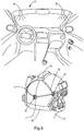
- sensor 10 may be coupled to a housing 34 that houses a processor 102 (shown in Figure 1 ) and a database 104 (shown in Figure 1 ) via wiring 42.
- one or more light source 38 (such as light emitting diode) is mounted at a fixed and predetermined location in a canopy 40 of a vehicle or an aircraft (shown schematically).
- light source 38 is a light emitting diode. In one aspect, light source 38 has a wave length in a range of from about 950 nm and about 1100 nm. In one aspect, light source 38 is light emitting diode configured to transmit a beam of light toward sensor 10. In one aspect, sensor 10 measures the beam of light and outputs an azimuth/elevation signal to processor 102. In one aspect, sensor 10 generates azimuth/elevation signal based on ratios of light intensity readings from photodetector array 18 comprising a plurality of photodetectors 18a-18d in sensor 10. In another aspect, each photodetector 18a-18d generates a voltage correlated to the intensity of light incident on its surface.
- a processor converts each voltage into a digital number and then calculates light intensity ratios therefrom.
- a plurality of sensors 10 may be mounted to helmet 28 and configured to output a plurality of azimuth/elevation signals to processor 102.
- processor 102 receives the azimuth/elevation signal from the sensor 10 and calculates the orientation of the helmet 28 relative to the light emitting diode 38 based on the angle of incident light from light source 38 (e.g. light emitting diode) as measured by sensor 10.
- processor 102 calculates the orientation of helmet 28 relative to the object to which light source 38 is mounted by first calculating the azimuth angle and elevation angle of light source 38 (such as a light emitting diode) based on the azimuth/elevation signal received from sensor 10. In one aspect, processor 102 then compares the measured azimuth angle and measured elevation angle to a predetermined azimuth angle and a predetermined elevation angle stored in database 104. In one aspect, the predetermined azimuth angle and elevation angle correspond to the location of light source 38 (such as a light emitting diode) when helmet 28 is pointing forward in canopy 40.
- processor 102 calculates a new orientation of helmet 28 relative to light source 38 (such as a light emitting diode).
- light source 38 such as a light emitting diode.
- a system for detecting a light source in accordance with the present invention can be advantageously configured for use in a battle field or in any hostile fire situation.
- the system for detecting a light source may be advantageous used by an infantry soldier to detect the presence and/or whereabouts of a hostile fire, such as hostile gunfire, and use the knowledge of the bearing of the location of the detected hostile fire to counter the danger posed by the hostile fire.
- the light source that can be detected by the system for detecting a light source includes a muzzle flash.
- the system for detecting a light source is versatile because it can be dimensioned to be relatively small and wearable on a headgear or any suitable part of the body of a user, for example, a soldier.
- the system for detecting a light source can be coupled to an infantry helmet and used to identify the source of a single light source 360° in both azimuth and elevation relative to the helmet reference frame.
- the azimuth and elevation of the light source can be displayed in a useable format to alert the infantry helmet wearer to the origin of the light source.
- the helmet reference frame can be related to the earth reference frame through the use of a ground helmet tracker.
- Fig. 10 illustrates an example flow diagram of a method 1000 for tracking an orientation of a first object in accordance with aspects of the present invention. As shown in Fig. 10 , in block 1002, emitting a light via a light emitting device located relative to a second object at a fixed predetermined position.
- Fig. 11 illustrates an example flow diagram of a method 1100 for detecting a direction from an object to a first light source in accordance with aspects of the present invention.
- Fig. 11 in block 1102, detecting, via an optical sensor mounted with a predetermined orientation on the object, the first light source.
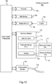
- aspects of the present invention may be implemented using hardware, software, or a combination thereof and may be implemented in one or more computer systems or other processing systems. In one variation, aspects of the invention are directed toward one or more computer systems capable of carrying out the functionality described herein. An example of such a computer system 700 is shown in Fig. 12 .
- Computer system 700 includes one or more processors, such as processor 704.
- the processor 704 is connected to a communication infrastructure 706 (e.g., a communications bus, a cross-over bar, or a network).
- a communication infrastructure 706 e.g., a communications bus, a cross-over bar, or a network.
- Computer system 700 can include a display interface 702 that forwards graphics, text, and other data from the communication infrastructure 706 (or from a frame buffer not shown) for display on a display unit 730.
- Computer system 700 also includes a main memory 708, such as random-access memory (RAM), and may also include a secondary memory 710.
- the secondary memory 710 may include, for example, a hard disk drive 712 and/or a removable storage drive 714, representing a floppy disk drive, a magnetic tape drive, an optical disk drive, etc.
- the removable storage drive 714 reads from and/or writes to a removable storage unit 718 in a well-known manner.
- Removable storage unit 718 represents a floppy disk, a magnetic tape, a thumb drive, an optical disk, etc., which is read by and written to removable storage drive 714.
- the removable storage unit 718 includes a computer usable storage medium having stored therein computer software and/or data.
- secondary memory 710 may include other similar devices for allowing computer programs or other instructions to be loaded into computer system 700.
- Such devices may include, for example, a removable storage unit 722 and an interface 720.
- Examples of such may include a program cartridge and a cartridge interface (such as that found in video game devices), a removable memory chip (such as an erasable programmable read-only memory (EPROM) or a programmable read-only memory (PROM)) and associated socket, and other removable storage units 722 and interfaces 720, which allow software and data to be transferred from the removable storage unit 722 to computer system 700.
- EPROM erasable programmable read-only memory
- PROM programmable read-only memory
- Computer system 700 may also include a communications interface 724.
- Communications interface 724 allows software and data to be transferred between computer system 700 and external devices. Examples of communications interface 724 may include a modem, a network interface (such as an Ethernet card), a communications port, a Personal Computer Memory Card International Association (PCMCIA) slot and card, etc.
- Software and data transferred via communications interface 724 are in the form of signals, which may be electronic, electromagnetic, optical, or other signals capable of being received by communications interface 724. These signals are provided to communications interface 724 via a communications path (e.g., channel) 726.
- This path 726 carries signals and may be implemented using wire or cable, fiber optics, a telephone line, a cellular link, a radio frequency (RF) link, and/or other communications channels.
- RF radio frequency
- computer program medium “computer-usable medium,” and “computer-readable medium” are used to refer generally to media such as a removable storage drive 714, a hard disk installed in hard disk drive 712, and signals.
- These computer program products provide software to the computer system 700. Aspects of the invention are directed to such computer program products.
- Computer programs are stored in main memory 708 and/or secondary memory 710. Computer programs may also be received via communications interface 724. Such computer programs, when executed, enable the computer system 700 to perform the features in accordance with aspects of the present invention, as discussed herein. In particular, the computer programs, when executed, enable the processor 704 to perform such features. Accordingly, such computer programs represent controllers of the computer system 700.
- aspects of the invention are implemented using software
- the software may be stored in a computer program product and loaded into computer system 700 using removable storage drive 714, hard disk drive 712, or communications interface 720.
- the control logic when executed by the processor 704, causes the processor 704 to perform the functions as described herein.
- aspects of the invention are implemented primarily in hardware using, for example, hardware components, such as application-specific integrated circuits (ASIC's). Implementation of the hardware state machine so as to perform the functions described herein will be apparent to persons skilled in the relevant art(s).
- aspects of the invention are implemented using a combination of both hardware and software.
Landscapes
- Physics & Mathematics (AREA)
- General Physics & Mathematics (AREA)
- Health & Medical Sciences (AREA)
- Engineering & Computer Science (AREA)
- Electromagnetism (AREA)
- Remote Sensing (AREA)
- Radar, Positioning & Navigation (AREA)
- General Health & Medical Sciences (AREA)
- Life Sciences & Earth Sciences (AREA)
- Immunology (AREA)
- Pathology (AREA)
- Chemical & Material Sciences (AREA)
- Nuclear Medicine, Radiotherapy & Molecular Imaging (AREA)
- Biochemistry (AREA)
- Analytical Chemistry (AREA)
- Spectroscopy & Molecular Physics (AREA)
- Length Measuring Devices By Optical Means (AREA)
Description
- The present Application for Patent is a Continuation-in-Part of Non-Provisional Patent Application
13/559,332 61/511,811 filed July 26, 2011 61/798,733 - Aspects of the present invention generally relate to light source location detection and, more particularly, to systems for gunfire detection and for helmet orientation detection. The publication
WO 2010/084222 discloses an optical sensor for detecting a direction to a light source comprising a plurality of photosensitive cells covered with a sheet of opaque material provided with a window. - In accordance with the present invention, respective systems, methods and computer program product, as set forth in the independent claims are provided. Embodiments of the invention are claimed in the dependent claims.
- According to an aspect of the present invention, a system for detecting a light source may include a housing having a front side and a back side, the back side being opposed to the front side and spaced therefrom; a photodetector array with at least two pixels located at the back side wall within the housing; an aperture extending through the front side of the housing that is spaced from the photodetector array an equivalent distance as the size of the aperture and configured to expose the photodetector array to an incident light from the light source; and a processor coupled to the plurality of photocells and configured to detect the light source.
- According to another aspect of the present invention, a system for tracking an orientation of a first object may include a light emitting device located relative to a second object at a fixed predetermined position; a sensor having a photodetector array that receives incident light emitted from the light emitting device, the photodetector array being mounted on the first object; and a processor coupled to the photodetector array, the processor being configured to determine the orientation of the first object relative to the second object based on an angle of incident light detected by the photodetector array from the light emitting device.
- According to yet another aspect of the present invention, a system for detecting a direction from an object to a first light source may include an optical sensor mounted with a predetermined orientation on the object, the optical sensor configured to detect the first light source and to measure the direction to the first light source with respect to the optical sensor; and a processor configured to transform the direction of the first light source with respect to the optical sensor into a direction with respect to the object using the predetermined orientation of the optical sensor on the object.
- According to yet another aspect of the present invention, a method for tracking an orientation of a first object may include emitting a light via a light emitting device located relative to a second object at a fixed predetermined position; detecting, via a sensor having a photodetector array, the light emitted from the light emitting device, the photodetector array being mounted on the first object; and determining, via a processor coupled to the photodetector array, the orientation of the first object relative to the second object based on an angle of the light detected by the photodetector array from the light emitting device.
- According to yet another aspect of the present invention, a method for detecting a direction from an object to a first light source may include detecting, via an optical sensor mounted with a predetermined orientation on the object, the first light source; measuring, via the optical sensor, the direction to the first light source with respect to the optical sensor; and transforming, via a processor, the direction of the first light source with respect to the optical sensor into a direction with respect to the object using the predetermined orientation of the optical sensor on the object.
- According to yet another aspect of the present invention, a system for tracking an orientation of a first object may include means for emitting a light, wherein the emitting means is located relative to a second object at a fixed predetermined position; means for detecting the light emitted from the means for emitting, the means for detecting being mounted on the first object; and means for determining the orientation of the first object relative to the second object based on an angle of the light detected by the detecting means.
- According to yet another aspect of the present invention, a system for detecting a direction from an object to a first light source may include means for detecting the first light, the means for detecting being mounted with a predetermined orientation on the object; means for measuring the direction to the first light source with respect to the means for detecting; and means for transforming the direction of the first light source with respect to the means for detecting into a direction with respect to the object using the predetermined orientation of the means for detecting on the object.
- According to yet another aspect of the present invention, a computer program product may include a non-transitory computer-readable medium having control logic stored therein for causing a computer to track an orientation of a first object, the control logic including code for emitting a light via a light emitting device located relative to a second object at a fixed predetermined position; code for detecting, via a sensor having a photodetector array, the light emitted from the light emitting device, the photodetector array being mounted on the first object; and code for determining, via a processor coupled to the photodetector array, the orientation of the first object relative to the second object based on an angle of the light detected by the photodetector array from the light emitting device.
- According to yet another aspect of the present invention, a computer program product may include a non-transitory computer-readable medium having control logic stored therein for causing a computer to detect a direction from an object to a first light source, the control logic including code for detecting, via an optical sensor mounted with a predetermined orientation on the object, the first light source; code for measuring, via the optical sensor, the direction to the first light source with respect to the optical sensor; and code for transforming, via a processor, the direction of the first light source with respect to the optical sensor into a direction with respect to the object using the predetermined orientation of the optical sensor on the object.
- It is understood that other aspects of the invention will become readily apparent to those skilled in the art from the following detailed description, wherein various aspects of the present invention are shown and described by way of illustration only. As will be understood, the present invention is capable of other and different variations and its several details are capable of modification in various other respects, all without departing from the scope of the invention. Accordingly, the drawings and detailed description are to be regarded as illustrative in nature and not as restrictive.
- These and other sample aspects of the disclosure will be described in the detailed description and the appended claims that follow, and in the accompanying drawings, wherein:
-
Figure 1 is a schematic view of a system for light source location in accordance with an exemplary aspect of the present invention; -
Figure 2 is a perspective cutaway view of a sensor in the system ofFigure 1 in accordance with an exemplary aspect of the present invention; -
Figure 3 is sectional view of the sensor ofFigure 2 taken along the line A-A in accordance with an exemplary aspect of the present invention; -
Figure 4 is a perspective view of the photodetector array of the sensor shown inFigure 2 coupled to a processor in accordance with an exemplary aspect of the present invention; -
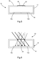
Figure 5 is a schematic cross-sectional side view of the sensor ofFigure 1 in accordance with an exemplary aspect of the present invention; -
Figure 6 is a schematic cross-sectional side view of the sensor ofFigure 1 showing light entering the sensor at different incident angles in accordance with an exemplary aspect of the present invention; -
Figure 7 shows the system ofFigure 1 having a plurality of sensors coupled to a helmet in accordance with an exemplary aspect of the present invention; -
Figures 8A-8N show a plurality of top views of states of a photodetector array of the sensor ofFigure 1 exposed to light at various incident angles in accordance with an exemplary aspect of the present invention; -
Figure 9 shows the system ofFigure 1 having a plurality of sensors coupled to a helmet for helmet orientation detection in a vehicle in accordance with an exemplary aspect of the present invention; -
Fig. 10 depicts an example flow diagram of a method for tracking an orientation of a first object in accordance with aspects of the present invention; -
Fig. 11 depicts an example flow diagram of a method for detecting a direction from an object to a first light source in accordance with aspects of the present invention; and -
Fig. 12 depicts a computer system for implementing various aspects of the present invention. - In accordance with common practice, the various features illustrated in the drawings may be simplified for clarity. Thus, the drawings may not depict all of the components of a given apparatus or method. In addition, like reference numerals may be used to denote like features throughout the specification and figures.
- Various aspects of the present invention are described below. It should be apparent that the teachings herein may be embodied in a wide variety of forms and that any specific structure, function, or both being disclosed herein may be merely representative. Based on the teachings herein one skilled in the art should appreciate that an aspect disclosed herein may be implemented independently of any other aspects and that two or more of these aspects may be combined in various ways. For example, an apparatus may be implemented or a method may be practiced using any number of the aspects set forth herein. In addition, such an apparatus may be implemented or such a method may be practiced using other structure, functionality, or structure and functionality, in addition to or other than one or more of the aspects set forth herein. An aspect may comprise one or more elements of a claim.
- Referring to the drawings in detail, wherein like reference numerals indicate like elements throughout, there is shown in
Figures 1-9 a system, generally designated withreference numeral 100, for detecting the location of a light source, in accordance with exemplary aspects of the present invention. - A gunfire detection system that can identify the spatial location and/or the elevation angle of gunfire can be useful in warfare situations, for example, to identify azimuthal and/or elevation angle of a gun user such as a sniper. As such, it is desirable to have a gunfire detection system that is simple in design, physically robust, and functions reliably under a variety of conditions, including under chaotic war conditions and/or inclement weather conditions.
- In order to maximize utility of a gunfire detection system on a battle field, for example, while minimizing the likelihood of it malfunctioning, it is desirable for the gunfire detection system to operate effectively without reliance on any complicated hardware and software packages. Therefore, a need exists for a gunfire detection system that is simple in design, economical, and preferably physically small in size. Such a simple gunfire detection system is more likely to function reliably under various environmental conditions, including inclement weather and battlefield conditions, than a gunfire detection system requiring expensive (magnifying/miniaturizing) lens systems, a camera, and/or complicated computer-implemented image processing components and algorithms.
- Furthermore, a gunfire detection system that comprises simple components that are readily available and/or do not require extensive customization is easier to maintain and to replace if it malfunctions. Thus, the gunfire detection system can be designed not only to be wearable and/or mountable on a person's appendage or a headgear, such as a helmet, but also to be readily repairable and/or replaceable if it malfunctions.
- Another advantage of having a gunfire detection system that is physically dimensioned to be easily wearable and/or mountable on a person's appendage, clothing or a headgear, such as a helmet, is that a plurality of the sensors can be distributed to and be worn by many individuals, who can independently of one another, detect gunfire. Also, a plurality of gunfire detection sensors can be mounted onto a headgear or clothing or appendage of a single individual, each sensor being configured to monitor a specific range of azimuth angles so that the plurality of the gunfire detection sensors can collectively monitor the entire range of azimuth angles: from 0° (north) through 90° (east), 180° (south), 270° (west), and up to 360° (north again), and elevation angles above the horizon from: 0° (at the horizon) up to 90° (at the zenith), down to 0° (at the horizon in the opposite direction) and below the horizon (downward) from 0° (at the horizon) to - 90° (at the nadir), and from the nadir up to 0° (at the horizon again).
- A system for detecting light source location, such as gunfire, in accordance with the present invention, in some aspects, includes a sensor which comprises a housing; a photodetector array configured to sense light that enters the housing through an aperture in a side of the housing. In one aspect, the aperture is configured to expose the photodetector array to light from a light source; and a processor coupled to the photodetector array and configured to detect the position, direction and/or location of the light source.
- Referring to
Figures 1 and 2 , asystem 100 for detecting light location in accordance with an exemplary aspect of the present invention includes asensor 10;sensor 10 having ahousing 12;housing 12 having afront side 14 and aback side 16, whereinback side 16 is opposed tofront side 14 and spaced therefrom.Housing 12 serves as a protective cover to protect components ofsensor 10 from certain physical impacts, inclement weather or any other adverse environmental conditions. In one aspect,housing 12 is opaque. - In one aspect,
sensor 10 includes aphotodetector array 18 located withinhousing 12 at thebackside 16 ofhousing 12. In one aspect,photodetector array 18 comprises two ormore photodetectors 18a-18d. In one aspect, eachphotodetector 18a-18d comprises one pixel. In one aspect, eachphotodetector 18a-18d comprises a plurality of pixels. In some aspects, eachphotodetector 18a-18d comprises a plurality of photocells and/or photoresistors. In one aspect,photodetector array 18 comprises at least two pixels. In another aspect,photodetector array 18 is configured to receive light that entershousing 12 ofsensor 10 throughaperture 20 infront side 14 ofhousing 12. In one aspect,photodetector array 18 outputs a signal indicating a detection of light from an incident light impinging on one ormore photodetectors 18a-18d. In one aspect ofphotodetector array 18,photodetectors 18a-18b, shown inFigures 2-6 , are spaced apart from each other bygap 24. - In one aspect, as shown in
Figures 2 and4 ,sensor 10 includesphotodetector array 18 comprising a two-by-two array ofphotodetectors 18a-18d. In another aspect, as shown inFigure 4 ,processor 102 is coupled tophotodetector array 18. In one aspect,photodetector array 18 may be of any suitable shape, including square shape and rectangular shape. In another aspect,photodetector array 18 may have any suitable physical dimensions. In another aspect,photodetector array 18 is configured to produce an electrical signal in response to the presence or absence of incident electromagnetic radiation. In another aspect,photodetector array 18 is configured to sense an incident electromagnetic radiation in or adjacent to the ultraviolet, visible or infrared frequency ranges. In an aspect,photodetector array 18 is configured to produce a spectrum of responses depending on the frequency of the incident electromagnetic radiation. In another aspect,photodetector array 18 is configured to be more sensitive to radiation within a certain frequency range (e.g., 400 THz to 790 THz or a wavelength of from wavelengths from about 900 nm to about 1100 nm) without producing a corresponding electrical signal when radiated with light of an adjacent or a remote frequency range. - In one aspect,
front side 14 ofhousing 12 has a window or anaperture 20 extending through it and configured to receive light from the environment ofsensor 10 and expose at least a portion of the interior ofhousing 12 to the received light. As shown inFigure 2 ,backside 16 defines a wall at whichphotodetector array 18 may be located withinhousing 12. In another aspect,processor 102 analyzes output signals ofphotodetector array 18 and calculates spatial parameters in order to detect a light source, such as gunfire. In one aspect,processor 102 may be further coupled to a head-mounted display (HMD), a computer, and/or adatabase 104.Processor 102, in some aspects, is coupled to head-mounted display (HMD), computer, and/ordatabase 104 via one or more wires. In other aspects,processor 102 is wirelessly coupled to head-mounted display (HMD), computer, and/ordatabase 104. - Referring to
Figures 1 and 2 , in one aspect,housing 12 ofsensor 10 is configured to allow exposure of at least a portion of the interior ofhousing 12 only to light enteringhousing 12 throughaperture 20, which extends throughfront side 14 ofhousing 12. In one aspect, as shown inFigure 3 ,housing 12 has a thickness T. In another aspect,housing 12 has a thickness T configured to be sufficiently small relative to length or width D ofaperture 20 to allowphotodetector array 18 to be exposed to greater amount of light enteringhousing 12 throughaperture 20. In one aspect, length or width D ofaperture 20 has a value that is substantially equal to the height or width W of a square or rectangular at least one ofphotodetectors 18a-18d. In one aspect,aperture 20 is configured to exposephotodetector array 18 located at the backside wall ofbackside 16 withinhousing 12 to an incident light, resulting from a source such as gunfire. Althoughaperture 20, as shown inFigures 1 and 2 , is square in shape,aperture 20 of any suitable shape and/or size may be used. In one aspect,aperture 20 has a length or width D. In another aspect,aperture 20 is rectangular, slit, circular or other preferred shapes. - In one aspect, as shown in the aspects of
Figures 2 and3 , the center ofaperture 20 is symmetrically aligned with the center ofphotodetector array 18 located withinhousing 12. In some aspects, an advantage of the symmetrical arrangement ofaperture 20 is that it simplifies any computations that may be performed to reveal spatial orientation (e.g., azimuth, direction) and/or elevation angle of light source. In one aspect, such as shown inFigure 5 ,sensor 10 includes anaperture cover 26 coveringaperture 20. In another aspect,aperture cover 26 is flush withaperture 20. In another aspect,aperture cover 26 is positioned withinhousing 12. In another aspect,aperture cover 26 is disposed inaperture 20. In another aspect,aperture cover 26 extends acrossfront side 14 andaperture 20. In one aspect,aperture 20 is a transparent portion ofhousing 12. - In one aspect,
aperture cover 26 is configured to permit light coming from a light source to pass throughaperture 20 without substantially distorting (e.g., bending, magnifying or miniaturizing) the light. In another aspect,aperture cover 26 is configured to permit light to pass throughaperture 20 with minimal distortion (magnification or miniaturization) of the light. In another aspect,aperture cover 26 provides further protection for the components ofsensor 10 against adverse environmental conditions, including inclement weather and dust particles. - In one aspect,
aperture cover 26 is comprised of a transparent material. In one aspect,aperture cover 26 is comprised of plastic, glass, quartz or any other transparent material or a combination thereof. However, any suitable material that can permit passage of light therethrough with minimal distortion (magnification or miniaturization) of light can be used. In some aspects,sensor 10 has no lens withinaperture 20 orhousing 12. In one aspect,aperture cover 26 decreases the expense and weight ofsensor 10. In other aspects, cover 26 includes a lens to magnify or miniaturize the incidentlight entering aperture 20. In one aspect, cover 26 is used to magnify or miniaturize the incidentlight entering aperture 20 in order to alter the range of light source detection. - Referring to
Figures 2 and4 , in one aspect,sensor 10 includesphotodetector array 18. In one aspect,sensor 10 includes includes aphotodetector array 18 having a two-by-two array ofphotodetectors 18a-18d. In another aspect, at least one ofphotodetectors 18a-18b is arranged to be illuminated/activated by an incidentlight entering sensor 10 throughaperture 20. In one aspect, eachphotodetector 18a-18d includes at least one photocell and/or photoresistor that is configured to be illuminated/activated by a portion of incident light and to generate an output signal/reading, which may be compared with the output signals of other activated photocells and/or photoresistors withinphototdetector array 18 to provide information about spatial orientation (an azimuth and/or an elevation) of the source of the incident light, e.g. gunfire. - In one aspect,
aperture 20 is a distance L fromphotodector array 18. In one aspect, distance L is equal to lateral width or length W of aphotodetector - In one aspect, each
photodetector 18a-18d detects whether it has been exposed to light or no light. In one aspect, eachphotodetector 18a-18d comprises a binary photocell or a photoresistor. In one aspect, an advantage of having eachphotodetector 18a-18d comprising a binary photocell or photoresistor is that the symmetry ofphotodetector array 18 simplifies any computations required to compare output signals (light intensity readings) of the constituent binary photocells and/or photoresistors. As, shownFigures 6 and8 , different entrance (incident) angles of light, each represented by three parallel lines inFigure 6 , enteringsensor 10 throughaperture 20, lead to activation of different regions of the light-receiving surface of thephotodetector array 18. Accordingly, while the shownphotodetector array 18 comprises only fourphotodetectors 18a-18d in a two-by-two array arrangement, there are at least fourteen (14) potentially distinguishable states ofphotodetector array 18, as shown inFigures 8A-8N , depending on whether a set of 0, 1, 2, 3 or 4 ofphotodetectors 18a-18d is activated by an incident light. For example, in a two-by-two array ofphotodetectors 18a-18d, when none ofphotodetectors 18a-18d is exposed to light, the state ofphotodetector array 18 is illustrated byFigure 8A . When all four ofphotodetectors 18a-18d are exposed to light, as shown inFigure 8B , the incident light is striking all ofphotodetectors 18a-18d at an incident elevation angle of approximately normal to the plane of photocells, or along the sensor central optical axis, and/orphotodetector array 18, indicating the light source is directly abovesensor 10. In another example, if only one ofphotodetectors 18a-18d is exposed to light, as shown inFigures 8C-8F , incident light is striking the surface of thephotodetector array 18 at an incident elevation angle of approximately 45° relative to the plane ofphotodetector array 18 and is originating from a light source located approximately in the same direction asphotodetectors 18a-18d located diagonally relative to one ofphotodetectors 18a-18d that is exposed to the light. In other words, the light source is at an elevation angle of approximately 45° relative to the plane ofphotodetector array 18 as shown inFigure 8G and is located at an azimuth of 135° relative to the top edge center ofsensor 10 ofFigure 8C , an azimuth of 315° relative to the top edge center ofsensor 10 ofFigure 8D , at an azimuth of 225° relative to the top edge center ofsensor 10 ofFigure 8E , or at an azimuth of 45° relative to the top edge center of thesensor 10 ofFigure 8F . - In another example, if two adjacent photocells and/or
photoresistors 18a-18d are exposed to light, as shown inFigures 8H-8K , the elevation angle of incidence is approximately 67.5° relative to the plane of thephotodetector array 18 as shown inFigure 8L and the light source is in the same direction as theopposite photodetectors 18a-18d. In other words, the light source is at an incident elevation angle of approximately 67.5° relative to the plane ofphotodetector array 18 and is located at an azimuth of 180° relative to the plane ofsensor 10 in the case ofFigure 8H , at an azimuth of 90° relative to the plane ofsensor 10 in the case ofFigure 8I , at an azimuth of 270° relative to the plane ofsensor 10 in the case ofFigure 8J , or at an azimuth of 0° relative to the plane ofsensor 10 in the case ofFigure 8K . In another example, if threeadjacent photocells 18 are exposed to light, as shown inFigures 8M-8P , the light is strikingphotodetector array 18 at an incident elevation angle that is greater than 67.5° but less than 90° relative to the plane ofphotodetector array 18 and the light source is located in the same direction as theother photodetectors 18a-18d that are not exposed to light. In other words, the light source is at an incident elevation angle between 45° and 90° relative to the plane ofphotodetector array 18 and is located at an azimuth of 135° relative to the plane ofsensor 10 in the case ofFigure 8M , at an azimuth of 45° relative to the plane ofsensor 10 in the case ofFigure 8N , at an azimuth of 315° relative to the plane ofsensor 10 in the case ofFigure 8O , or at an azimuth of 225° relative to the plane ofsensor 10 in the case ofFigure 8P . - In some aspects of the present invention, the photodetectors in
Figures 8A-8P may be analog photodetectors, and may be used when all four cells are receiving some light, so that ratios can be computed to determine precise angles to the light source. For example, in an aspect of the present invention, the sensor is primarily used as an analog direction sensor. This mode of operation corresponds to the situation when all four quadrants receive at least a some of the light spot, as illustrated inFigures 8B ,8M, 8N, 8O, and 8P . In one aspect, examples of photodetectors suitable for use in accordance with the present invention are described inU.S. Patent Application Serial No. 13/559,332, filed July 26, 2012 - Additional states of
photodetector array 18 may be specified based on a percentage of the different regions ofphotodetector array 18 that is activated by an incident light. Accordingly, there are potentially more than 14 states of the aspect ofphotodetector array 18 having a two-by-two array ofphotodetectors 18a-18d that may be specified and used to specify spatial location/direction/orientation of light source with high level of granularity. Althoughsensor 10 is being illustrated herein as havingphotodetector array 18 comprising a two-by-two array ofphotodetectors 18a-18d,sensor 10 may havephotodetector array 18 that comprises any number ofphotodetectors 18a-18d. - Accordingly, in one aspect,
sensor 10 may includephotodetector array 18 includes a plurality ofphotodetectors 18a-18d arranged in at least two rows. In another aspect, each row ofphotodetectors 18a-18d may be arranged in a single plane. In a further aspect, each row ofphotodetectors 18a-18d includes at least two photodetectors. In another aspect, each row ofphotodetectors 18a-18d includes an equal number of photodetectors. In another aspect,photodetector array 18 includes an array in which each row of photocells and/orphotoresistors 18a-18d includes two photocells and/orphotoresistors 18a-18d. In another aspect,photodetector array 18 includes an even number ofphotodetectors 18a-18d. - In one aspect, as shown in
Figures 2-6 ,photodetector array 18 includes an array in whichphotodetectors 18a-18d are arranged in two parallel rows. In another aspect,photodetector array 18 includes an array in whichphotodetectors 18a-18d are spaced apart from each other bygap 24. In another aspect,photodetector array 18 includes an array in whichphotodetectors 18a-18d are arranged in parallel relation so as to form a plurality of parallel columns and parallel rows ofphotodetectors 18a-18d. In another aspect,photodetector array 18 includes at least one or more rows ofphotodetectors 18a-18d having a different number ofphotodetectors 18a-18d. In another aspect,photodetector array 18 includes at least one ofphotodetectors 18a-18d spaced apart from one or more otheradjacent photodetectors 18a-18d bygap 24. In another aspect,photodetector array 18 includes one ormore photodetectors 18a-18d are in contiguous relation with one or moreadjacent photodetectors 18a-18d. - In one aspect,
photodetector array 18 is responsive to reception oflight entering sensor 10 throughaperture 20 to provide electrical an output representative of spatial location and/or orientation of an incident light with respect to the plane ofphotodetector array 18. - In one aspect of
photodetector array 18, output signals (light intensity readings) of one or more photocells and/orphotoresistors 18a-18d are detectably associable with relative positions of the one or more photocells and/orphotoresistors 18a-18d withinphotodetector array 18. In another aspect ofphotodetector array 18, output signals (light intensity readings) of one ormore photodetectors 18a-18d are detectably associable with relative orientations of one ormore photodetectors 18a-18d within photodetector arrayl8. In yet another aspect ofphotodetector array 18, output signals (light intensity readings) of one ormore photodetectors 18a-18d are detectably associable with relative positions of one ormore photodetectors 18a-18d and spatial orientations of one ormore photodetectors 18a-18d withinphotodetector array 18. - As shown in
Figures 1 and4 , in one aspect,system 100 includes aprocessor 102 coupled tophotodetector array 18. In one aspect,processor 102 serves to perform necessary calculations using the information received fromphotodetector array 18 to provide an output signal representative of azimuth and/or elevation angle of incident light relative to the plane ofsensor 10. In one aspect,processor 102 is configured to detect light source on the basis of variation in light intensity readings detected at one or more regions ofphotodetector array 18 that are illuminated/activated by alight entering sensor 10 throughaperture 20. In another aspect,signal processor 102 is configured to be responsive to output signals fromphotodetector array 18 and for evaluating output signals fromphotodetector array 18 and to calculate azimuth and/or elevation angle of incident light relative to the plane ofsensor 10. In one aspect, output signals ofphotodetector array 18 comprise light intensity readings. In another aspect,processor 102 evaluates light intensity readings ofphotodetector array 18 and calculates azimuthal direction and/or elevation angle of incident light from the ratios of light intensity readings fromphotodetector array 18. - Referring to
Figures 6 and7 , azimuth and elevation angle generally define an apparent position of an object in the sky, relative to a specific observation point (sensor 10 in the present instant). Theobserver 30 inFigure 7 , in thiscase wearing sensor 10, is typically (but need not be) located on the earth's surface. Azimuth typically is the compass bearing, relative to true (geographic) north, of a point on the horizon directly beneath an observed object (e.g., gunfire). Horizon is conventionally defined as an imaginary circle centered on observer 30 (or sensor 10), equidistant from the zenith (point straight overhead) and the nadir (point exactly opposite the zenith). Compass bearings are commonly measured clockwise in degrees from north. Azimuth angles can thus range from 0 degrees (north) through 90 (east), 180 (south), 270 (west), and up to 360 (north again). - In some aspects, an elevation angle, or an altitude, of an observed object (e.g., gunfire) as would be understood by one of ordinary skill in the art could be determined by finding the compass bearing on the horizon relative to true north (geographic north), and then measuring the angle between that point and the object, from the reference frame of the observer (the system for gunfire detection 10). Elevation angles for objects (e.g., gunfire) above the horizon can range from 0 (on the horizon) up to 90 degrees (at the zenith). Sometimes the range of the elevation coordinate is extended downward from the horizon to -90 degrees (the nadir). This can be useful when observer 30 (or sensor 10) is located at some distance above the surface of the earth, such as in an aircraft during a flight.
- An azimuth direction and elevation angle of light source, such as gunfire, may be computed on the basis of light intensity readings of
photocells 18 as follows. - As shown in
Figure 7 , a plurality ofsensors 10 may be mounted to a side of aninfantry helmet 28, or any other headgear. Forsensor 10 to be mountable to a side ofinfantry helmet 28 is particularly advantageous, because each soldier can have his/her ownwearable sensors 10. Furthermore, when coupled toinfantry helmet 28,sensor 10 can be used to identify the source of a single light source 360° in both azimuth and elevation relative to the helmet reference frame and display information that will draw the wearer to the origin of the light source. The helmet reference frame can be related to the earth reference frame through the use of a ground helmet tracker. - As illustrated in
Figure 7 , in one aspect,sensors 10 may be coupled tohelmet tracker 32 to expand the range of capabilities ofhelmet tracker 32 beyond just estimating and predicting the position and orientation ofhelmet 28. In another aspect, a plurality ofsensors 10 may be coupled tohelmet tracker 32 to broaden the range of view and help pinpoint direction or location of light source such as hostile fire. In an aspect,helmet tracker 32 comprises a processor and a Global Positioning System (GPS). In one aspect, two ormore sensors 10 are positioned around different radial positions onhelmet 28. In one aspect,sensor 10 andprocessor 102 and/or computer ordatabase 104 is mounted tohelmet 28. In another aspect,processor 102 and/or computer ordatabase 104 are remotely located. In one aspect, examples of ahelmet tracker 32 suitable for use in accordance with the present invention are described inU.S. Patent Nos. 5,645,077 and7, 301, 648 . - In one aspect,
processor 102 and/or computer ordatabase 104 includes one or more computers having one or more processors and memory (e.g., one or more nonvolatile storage devices). In some aspects, a memory or a computer readable storage medium of memory stores programs, modules and data structures, or a subset thereof for a processor to control and run the various systems and methods disclosed herein. In one aspect, a non-transitory computer readable storage medium having stored thereon computer-executable instructions which, when executed by a processor, perform one or more of the methods disclosed herein. - Referring to
Figure 9 , in one aspect,sensor 10 may be coupled tohelmet 28 and used to detect the orientation of thehelmet 28 relative to an object. In one aspect, the object is a vehicle. In one aspect, the object is a cockpit of an airplane. In one aspect,sensor 10 may be coupled to ahousing 34 that houses a processor 102 (shown inFigure 1 ) and a database 104 (shown inFigure 1 ) viawiring 42. In one aspect, one or more light source 38 (such as light emitting diode) is mounted at a fixed and predetermined location in acanopy 40 of a vehicle or an aircraft (shown schematically). - In one aspect,
light source 38 is a light emitting diode. In one aspect,light source 38 has a wave length in a range of from about 950 nm and about 1100 nm. In one aspect,light source 38 is light emitting diode configured to transmit a beam of light towardsensor 10. In one aspect,sensor 10 measures the beam of light and outputs an azimuth/elevation signal toprocessor 102. In one aspect,sensor 10 generates azimuth/elevation signal based on ratios of light intensity readings fromphotodetector array 18 comprising a plurality ofphotodetectors 18a-18d insensor 10. In another aspect, eachphotodetector 18a-18d generates a voltage correlated to the intensity of light incident on its surface. In a further aspect, a processor converts each voltage into a digital number and then calculates light intensity ratios therefrom. In one aspect, a plurality ofsensors 10 may be mounted tohelmet 28 and configured to output a plurality of azimuth/elevation signals toprocessor 102. In one aspect,processor 102 receives the azimuth/elevation signal from thesensor 10 and calculates the orientation of thehelmet 28 relative to thelight emitting diode 38 based on the angle of incident light from light source 38 (e.g. light emitting diode) as measured bysensor 10. - In one aspect,
processor 102 calculates the orientation ofhelmet 28 relative to the object to whichlight source 38 is mounted by first calculating the azimuth angle and elevation angle of light source 38 (such as a light emitting diode) based on the azimuth/elevation signal received fromsensor 10. In one aspect,processor 102 then compares the measured azimuth angle and measured elevation angle to a predetermined azimuth angle and a predetermined elevation angle stored indatabase 104. In one aspect, the predetermined azimuth angle and elevation angle correspond to the location of light source 38 (such as a light emitting diode) whenhelmet 28 is pointing forward incanopy 40. Based on the difference between the measured azimuth and elevation angle compared to the stored azimuth angle and elevation angle,processor 102 calculates a new orientation ofhelmet 28 relative to light source 38 (such as a light emitting diode). In one aspect, examples of a motion tracking system and methods of using the same that are suitable for use in accordance with exemplary aspects of the present invention are described inU.S. Patent Nos. 6,409,687 and7, 000, 469 . - A system for detecting a light source in accordance with the present invention can be advantageously configured for use in a battle field or in any hostile fire situation. For a militaristic application, the system for detecting a light source may be advantageous used by an infantry soldier to detect the presence and/or whereabouts of a hostile fire, such as hostile gunfire, and use the knowledge of the bearing of the location of the detected hostile fire to counter the danger posed by the hostile fire. The light source that can be detected by the system for detecting a light source includes a muzzle flash. The system for detecting a light source is versatile because it can be dimensioned to be relatively small and wearable on a headgear or any suitable part of the body of a user, for example, a soldier. Moreover, the system for detecting a light source can be coupled to an infantry helmet and used to identify the source of a single light source 360° in both azimuth and elevation relative to the helmet reference frame. Importantly, the azimuth and elevation of the light source can be displayed in a useable format to alert the infantry helmet wearer to the origin of the light source. Furthermore, the helmet reference frame can be related to the earth reference frame through the use of a ground helmet tracker.
-
Fig. 10 illustrates an example flow diagram of amethod 1000 for tracking an orientation of a first object in accordance with aspects of the present invention. As shown inFig. 10 , inblock 1002, emitting a light via a light emitting device located relative to a second object at a fixed predetermined position. - In
block 1004, detecting, via a sensor having a photodetector array, the light emitted from the light emitting device, the photodetector array being mounted on the first object. - In
block 1006, determining, via a processor coupled to the photodetector array, the orientation of the first object relative to the second object based on an angle of the light detected by the photodetector array from the light emitting device. -
Fig. 11 illustrates an example flow diagram of amethod 1100 for detecting a direction from an object to a first light source in accordance with aspects of the present invention. As shown inFig. 11 , inblock 1102, detecting, via an optical sensor mounted with a predetermined orientation on the object, the first light source. - In block 1104, measuring, via the optical sensor, the direction to the first light source with respect to the optical sensor.
- In
block 1106, transforming, via a processor, the direction of the first light source with respect to the optical sensor into a direction with respect to the object using the predetermined orientation of the optical sensor on the object. - Aspects of the present invention may be implemented using hardware, software, or a combination thereof and may be implemented in one or more computer systems or other processing systems. In one variation, aspects of the invention are directed toward one or more computer systems capable of carrying out the functionality described herein. An example of such a
computer system 700 is shown inFig. 12 . -
Computer system 700 includes one or more processors, such asprocessor 704. Theprocessor 704 is connected to a communication infrastructure 706 (e.g., a communications bus, a cross-over bar, or a network). Various software aspects are described in terms of this exemplary computer system. After reading this description, it will become apparent to a person skilled in the relevant art(s) how to implement aspects of the invention using other computer systems and/or architectures. -
Computer system 700 can include adisplay interface 702 that forwards graphics, text, and other data from the communication infrastructure 706 (or from a frame buffer not shown) for display on adisplay unit 730.Computer system 700 also includes amain memory 708, such as random-access memory (RAM), and may also include asecondary memory 710. Thesecondary memory 710 may include, for example, ahard disk drive 712 and/or aremovable storage drive 714, representing a floppy disk drive, a magnetic tape drive, an optical disk drive, etc. Theremovable storage drive 714 reads from and/or writes to aremovable storage unit 718 in a well-known manner.Removable storage unit 718 represents a floppy disk, a magnetic tape, a thumb drive, an optical disk, etc., which is read by and written toremovable storage drive 714. As will be appreciated, theremovable storage unit 718 includes a computer usable storage medium having stored therein computer software and/or data. - In alternative variations,
secondary memory 710 may include other similar devices for allowing computer programs or other instructions to be loaded intocomputer system 700. Such devices may include, for example, aremovable storage unit 722 and aninterface 720. Examples of such may include a program cartridge and a cartridge interface (such as that found in video game devices), a removable memory chip (such as an erasable programmable read-only memory (EPROM) or a programmable read-only memory (PROM)) and associated socket, and otherremovable storage units 722 andinterfaces 720, which allow software and data to be transferred from theremovable storage unit 722 tocomputer system 700. -
Computer system 700 may also include acommunications interface 724. Communications interface 724 allows software and data to be transferred betweencomputer system 700 and external devices. Examples ofcommunications interface 724 may include a modem, a network interface (such as an Ethernet card), a communications port, a Personal Computer Memory Card International Association (PCMCIA) slot and card, etc. Software and data transferred viacommunications interface 724 are in the form of signals, which may be electronic, electromagnetic, optical, or other signals capable of being received bycommunications interface 724. These signals are provided tocommunications interface 724 via a communications path (e.g., channel) 726. Thispath 726 carries signals and may be implemented using wire or cable, fiber optics, a telephone line, a cellular link, a radio frequency (RF) link, and/or other communications channels. In this document, the terms "computer program medium," "computer-usable medium," and "computer-readable medium" are used to refer generally to media such as aremovable storage drive 714, a hard disk installed inhard disk drive 712, and signals. These computer program products provide software to thecomputer system 700. Aspects of the invention are directed to such computer program products. - Computer programs (also referred to as computer control logics) are stored in
main memory 708 and/orsecondary memory 710. Computer programs may also be received viacommunications interface 724. Such computer programs, when executed, enable thecomputer system 700 to perform the features in accordance with aspects of the present invention, as discussed herein. In particular, the computer programs, when executed, enable theprocessor 704 to perform such features. Accordingly, such computer programs represent controllers of thecomputer system 700. - In a variation where aspects of the invention are implemented using software, the software may be stored in a computer program product and loaded into
computer system 700 usingremovable storage drive 714,hard disk drive 712, orcommunications interface 720. The control logic (software), when executed by theprocessor 704, causes theprocessor 704 to perform the functions as described herein. In another variation, aspects of the invention are implemented primarily in hardware using, for example, hardware components, such as application-specific integrated circuits (ASIC's). Implementation of the hardware state machine so as to perform the functions described herein will be apparent to persons skilled in the relevant art(s). - In yet another variation, aspects of the invention are implemented using a combination of both hardware and software.
- While aspects of the present invention have been described in connection with preferred implementations, it will be understood by those skilled in the art that variations and modifications described above may be made without departing from the scope hereof. Other aspects will be apparent to those skilled in the art from a consideration of the specification or from a practice of the aspects of the invention disclosed herein.
- It will be appreciated by those skilled in the art that changes could be made to the exemplary aspects shown and described above without departing from the broad inventive concept thereof. It is understood, therefore, that this invention is not limited to the exemplary aspects shown and described, but it is intended to cover modifications within the scope of the present invention as defined by the claims. For example, specific features of the exemplary aspects may or may not be part of the claimed invention and features of the disclosed aspects may be combined.
- It is to be understood that at least some of the figures and descriptions of the invention have been simplified to focus on elements that are relevant for a clear understanding of the invention, while eliminating, for purposes of clarity, other elements that those of ordinary skill in the art will appreciate may also comprise a portion of the invention. However, because such elements are well known in the art, and because they do not necessarily facilitate a better understanding of the invention, a description of such elements is not provided herein.
- Further, to the extent that the method does not rely on the particular order of steps set forth herein, the particular order of the steps should not be construed as limitation on the claims. The claims directed to the method of the present invention should not be limited to the performance of their steps in the order written, and one skilled in the art can readily appreciate that the steps may be varied and still remain within the scope of the present invention.
Claims (12)
- A system (100) for tracking an orientation of a first object (28), the system comprising:a light emitting device (38) located relative to a second object (40) at a fixed predetermined position;a sensor (10) having a square two-by-two photodetector array (18) that is configured to receive incident light emitted from the light emitting device (38), the square two-by-two photodetector array (18) being mounted on the first object (28); anda processor (102) coupled to the square two-by-two photodetector array (18), the processor (102) configured to determine the orientation of the first object (28) relative to the second object (40) based on an angle of incident light detected by the square two-by-two photodetector array (18) from the light emitting device (38),wherein the sensor (10) includes:a housing (12) having a first side (14) and a second side (16), the second side (16) being opposite to the first side (14) and spaced therefrom, the square two-by-two photodetector array (18) being located proximal to the second side (16) within the housing (12); andan aperture (20) extending through the first side (14) of the housing and configured to expose the four photodetectors (18a-d) of the square two-by-two photodetector array (18) to an incident light from the light emitting device (38),wherein each of the four photodetectors (18a-d) is square shaped, and wherein the aperture (20) has the same square shape and dimensions as each photodetector, and wherein the aperture (20) is spaced from the square two-by-two photodetector array (18) by a distance equal to a width or length of the square shape of each photodetector; andwherein the processor (102) is configured to detect an angle of incidence of a light source based on light intensity readings detected at one or more regions of a light-receiving surface of the square two-by-two photodetector array (18) that are illuminated by light entering the sensor (10) through the aperture (20).
- The system (100) of claim 1, wherein the processor (102) is configured to arithmetically calculate at least one of: a measured azimuth direction and a measured elevation angle of the incident light from the light emitting device (38) to determine a measured position of the light emitting device (38).
- The system (100) of claim 2, wherein the processor (102) is configured to arithmetically calculate at least one of: the measured azimuth direction and the measured elevation angle of the incident light from the light emitting device (38) based on ratios of light intensity readings from the square two-by-two photodetector array (18).
- The system (100) of claim 2, wherein the processor (102) is configured to store the predetermined position of the light emitting device (38) in memory, the predetermined position of the light emitting device (38) including a predetermined azimuth direction and a predetermined elevation angle, the processor (102) configured to determine a difference between the at least one of: the measured azimuth direction and the measured elevation angle of the incident light from the light emitting device (38) to at least one of: the predetermined azimuth direction and the predetermined elevation angle, and the processor (102) calculates the orientation of the object (28) based on the difference.
- The system (100) of claim 1, wherein the light emitting device (38) is mounted inside a vehicle or cockpit (40).
- The system (100) of claim 1, wherein the light emitting device (38) is a light emitting diode.
- The system (100) of claim 1, wherein the first object (28) is a helmet.
- A system (100) for detecting a direction from an object (28) to a first light source, the system comprising:an optical sensor (10) mounted with a predetermined orientation on the object (28), the optical sensor (10) configured to detect the first light source (38) and to measure the direction to the first light source with respect to the optical sensor (10); anda processor (102) configured to transform the direction of the first light source with respect to the optical sensor (10) into a direction with respect to the object (28) using the predetermined orientation of the optical sensor (10) on the object (28),wherein the optical sensor (10) includes:a housing (12) having a first side (14) and a second side (16), the second side (16) being opposite to the first side (14) and spaced therefrom, a square two-by-two photodetector array (18) being located proximal to the second side (16) within the housing (12); andan aperture (20) extending through the first side (14) of the housing (12) and configured to expose the four photodetectors (18a-d) of the square two-by-two photodetector array (18) to an incident light from the first light source,wherein each of the four photodetectors (18a-d) is square shaped, and wherein the aperture (20) has the same square shape and dimensions as each photodetector, and wherein the aperture (20) is spaced from the square two-by-two photodetector array (18) by a distance equal to a width or length of the square shape of each photodetector; andwherein the processor (102) is configured to determine the direction to the first light source based on light intensity readings detected at one or more regions of a light-receiving surface of the square two-by-two photodetector array (18) that are illuminated by light from the first light source entering the sensor (10) through the aperture (20).
- The system (100) of claim 8 wherein the first light source is gunfire or a muzzle flash.
- A method for tracking an orientation of a first object (28), the method comprising:emitting a light via a light emitting device (38) located relative to a second object (40) at a fixed predetermined position;detecting, via a sensor (10) having a square two-by-two photodetector array (18), the light emitted from the light emitting device (38), the square two-by-two photodetector array (18) being mounted on the first object (28); anddetermining, via a processor (102) coupled to the square two-by-two photodetector array (18), the orientation of the first object (28) relative to the second object (40) based on an angle of the light detected by the square two-by-two photodetector array (18) from the light emitting device (38),wherein the sensor (10) includes:a housing (12) having a first side (14) and a second side (16), the second side (16) being opposite to the first side (14) and spaced therefrom, the square two-by-two photodetector array (18) being located proximal to the second side (16) within the housing (12); andan aperture (20) extending through the first side (14) of the housing and configured to expose the four photodetectors (18a-d) of the square two-by-two photodetector array (18) to an incident light from the light emitting device (38),wherein each of the four photodetectors (18a-d) is square shaped, and wherein the aperture (20) has the same square shape and dimensions as each photodetector, and wherein the aperture (20) is spaced from the square two-by-two photodetector array (18) by a distance equal to a width or length of the square shape of each photodetector; anddetermining, via the processor (102), the angle of incident light based on light intensity readings detected at one or more regions of a light-receiving surface of the square two-by-two photodetector array (18) that are illuminated by light from the light emitting device (38) entering the sensor (10) through the aperture (20).
- A method for detecting a direction from an object (28) to a first light source, the method comprising:detecting, via an optical sensor (10) mounted with a predetermined orientation on the object (28), the first light source;measuring, via the optical sensor (10), the direction to the first light source with respect to the optical sensor (10); andtransforming, via a processor (102), the direction of the first light source with respect to the optical sensor (10) into a direction with respect to the object (28) using the predetermined orientation of the optical sensor (10) on the object (28),wherein the optical sensor (10) includes:a housing (12) having a first side (14) and a second side (16), the second side (16) being opposite to the first side (14) and spaced therefrom, a square two-by-two photodetector array (18) being located proximal to the second side (16) within the housing (12); andan aperture (20) extending through the first side (14) of the housing (12) and configured to expose the four photodetectors (18a-d) of the square two-by-two photodetector array (18) to an incident light from the first light source,wherein each of the four photodetectors (18a-d) is square shaped, and wherein the aperture (20) has the same square shape and dimensions as each photodetector, and wherein the aperture (20) is spaced from the square two-by-two photodetector array (18) by a distance equal to a width or length of the square shape of each photodetector; anddetermining, via the processor (102), the direction to the first light source based on light intensity readings detected at one or more regions of a light-receiving surface of the square two-by-two photodetector array (18) that are illuminated by light from the first light source entering the sensor (10) through the aperture (20).
- A computer program product comprising a non-transitory computer-readable medium having control logic stored therein for causing the system of any of claims 1 - 7 to execute the steps of the method of claim 10, or for causing the system of any of claims 8 - 9 to execute the steps of the method of claim 11.
Applications Claiming Priority (3)
| Application Number | Priority Date | Filing Date | Title |
|---|---|---|---|
| US201361798733P | 2013-03-15 | 2013-03-15 | |
| US14/209,636 US9243902B2 (en) | 2011-07-26 | 2014-03-13 | System for light source location detection |
| PCT/US2014/028068 WO2014143900A2 (en) | 2013-03-15 | 2014-03-14 | System for light source location detection |
Publications (3)
| Publication Number | Publication Date |
|---|---|
| EP2972452A2 EP2972452A2 (en) | 2016-01-20 |
| EP2972452A4 EP2972452A4 (en) | 2017-01-25 |
| EP2972452B1 true EP2972452B1 (en) | 2020-05-06 |
Family
ID=51538283
Family Applications (1)
| Application Number | Title | Priority Date | Filing Date |
|---|---|---|---|
| EP14765624.3A Active EP2972452B1 (en) | 2013-03-15 | 2014-03-14 | System for light source location detection |
Country Status (6)
| Country | Link |
|---|---|
| US (1) | US9243902B2 (en) |
| EP (1) | EP2972452B1 (en) |
| ES (1) | ES2797375T3 (en) |
| IL (1) | IL241497B (en) |
| TW (1) | TW201504658A (en) |
| WO (1) | WO2014143900A2 (en) |
Families Citing this family (3)
| Publication number | Priority date | Publication date | Assignee | Title |
|---|---|---|---|---|
| US20150276391A1 (en) * | 2012-10-15 | 2015-10-01 | Fujitsu Limited | Direction discrimination device, direction discrimination method, and recording medium storing direction discrimination control program |
| US9927292B2 (en) | 2015-04-23 | 2018-03-27 | Asml Netherlands B.V. | Beam position sensor |
| CN113687574A (en) | 2020-05-18 | 2021-11-23 | 长鑫存储技术有限公司 | Lithography apparatus and method for monitoring the position of light source |
Family Cites Families (19)
| Publication number | Priority date | Publication date | Assignee | Title |
|---|---|---|---|---|
| US3678283A (en) | 1970-10-22 | 1972-07-18 | Us Navy | Radiation sensitive optical tracker |
| DE3213145A1 (en) * | 1982-04-08 | 1983-10-20 | Fa. Carl Zeiss, 7920 Heidenheim | MICROSCOPE PHOTOMETER |
| GB2143948B (en) * | 1983-07-23 | 1986-08-06 | Ferranti Plc | Apparatus for determining the direction of a line of sight |
| USH192H (en) | 1984-01-03 | 1987-01-06 | The United States Of America As Represented By The Secretary Of The Navy | Satellite alignment sensor |
| EP0344153B1 (en) * | 1986-11-27 | 1995-04-05 | David Fenton Fenner | Remote control systems |
| US5196689A (en) | 1990-10-16 | 1993-03-23 | Pioneer Electronic Corporation | Device for detecting an object including a light-sensitive detecting array |
| US5510893A (en) | 1993-08-18 | 1996-04-23 | Digital Stream Corporation | Optical-type position and posture detecting device |
| US5645077A (en) | 1994-06-16 | 1997-07-08 | Massachusetts Institute Of Technology | Inertial orientation tracker apparatus having automatic drift compensation for tracking human head and other similarly sized body |
| GB9420578D0 (en) | 1994-10-12 | 1994-11-30 | Secr Defence | Position sensing of a remote target |
| US5748321A (en) * | 1996-05-07 | 1998-05-05 | The United States Of America As Represented By The Department Of Energy | Position and orientation tracking system |
| US6176837B1 (en) | 1998-04-17 | 2001-01-23 | Massachusetts Institute Of Technology | Motion tracking system |
| US6424410B1 (en) | 1999-08-27 | 2002-07-23 | Maui Innovative Peripherals, Inc. | 3D navigation system using complementary head-mounted and stationary infrared beam detection units |
| AU2001233019A1 (en) | 2000-01-28 | 2001-08-07 | Intersense, Inc. | Self-referenced tracking |
| US7000469B2 (en) | 2000-04-21 | 2006-02-21 | Intersense, Inc. | Motion-tracking |
| US7732769B2 (en) | 2005-11-08 | 2010-06-08 | General Atomics | Apparatus and methods for use in flash detection |
| EP2201400B1 (en) | 2007-09-26 | 2014-03-05 | Elbit Systems Ltd. | Wide field of view optical tracking system |
| US8487837B2 (en) | 2008-11-06 | 2013-07-16 | Bae Systems Information And Electronic Systems Integration Inc. | Optical six-degree of freedom tracking apparatus and method |
| ES2346624B1 (en) * | 2009-01-23 | 2011-10-03 | Universidad De Sevilla | HIGH PRECISION DEVICE FOR THE DETERMINATION OF THE ANGLE OF INCIDENCE OF A LUMINISCENT RADIATION. |
| US8619267B2 (en) * | 2011-07-08 | 2013-12-31 | Avago Technologies General Ip (Singapore) Pte. Ltd. | Proximity sensor with motion detection |
-
2014
- 2014-03-13 US US14/209,636 patent/US9243902B2/en active Active
- 2014-03-14 ES ES14765624T patent/ES2797375T3/en active Active
- 2014-03-14 EP EP14765624.3A patent/EP2972452B1/en active Active
- 2014-03-14 WO PCT/US2014/028068 patent/WO2014143900A2/en not_active Ceased
- 2014-03-17 TW TW103109970A patent/TW201504658A/en unknown
-
2015
- 2015-09-10 IL IL241497A patent/IL241497B/en active IP Right Grant
Non-Patent Citations (1)
| Title |
|---|
| None * |
Also Published As
| Publication number | Publication date |
|---|---|
| IL241497B (en) | 2020-04-30 |
| WO2014143900A3 (en) | 2015-06-04 |
| US20150226546A1 (en) | 2015-08-13 |
| ES2797375T3 (en) | 2020-12-02 |
| US9243902B2 (en) | 2016-01-26 |
| IL241497A0 (en) | 2015-11-30 |
| EP2972452A4 (en) | 2017-01-25 |
| EP2972452A2 (en) | 2016-01-20 |
| WO2014143900A2 (en) | 2014-09-18 |
| TW201504658A (en) | 2015-02-01 |
Similar Documents
| Publication | Publication Date | Title |
|---|---|---|
| US9134174B2 (en) | Laser detection and warning system | |
| ES2554549T3 (en) | Search procedure for a thermal target | |
| US7349803B2 (en) | Daytime stellar imager | |
| US9269239B1 (en) | Situational awareness system and method | |
| US20080316462A1 (en) | Curved sensor array apparatus and methods | |
| US20080017784A1 (en) | Apparatus and methods to locate and track the sun | |
| US10393851B2 (en) | Polyhedral sensor arrangement and method for operating a polyhedral sensor arrangement | |
| WO2017100702A2 (en) | Unmanned aerial system based thermal imaging systems and methods | |
| US20140049772A1 (en) | Apparatus and Methods for Locating Source of and Analyzing Electromagnetic Radiation | |
| EP3430353B1 (en) | Celestial navigation system | |
| US20130002525A1 (en) | System for locating a position of an object | |
| US9243902B2 (en) | System for light source location detection | |
| WO2013034941A2 (en) | Method for measuring cloud-base distance and apparatus for measuring polarization | |
| US11879838B2 (en) | Vicarious calibration using solar glint over water | |
| US10032311B1 (en) | Synthetic image enhancing system, device, and method | |
| Minwalla et al. | Flight test evaluation of a prototype optical instrument for airborne sense-and-avoid applications | |
| CN210862923U (en) | Vehicle-mounted hyperspectral panoramic imaging detector | |
| Cavanaugh et al. | Cell tower contrast in the visible, short-wave infrared, and long-wave infrared bands | |
| RU2627016C1 (en) | Method for determining wind speed over water surface | |
| RU2616354C1 (en) | Method for determining wind speed above water surface | |
| RU2554519C1 (en) | Optical information extractor | |
| US20250182320A1 (en) | Automatic range and geo-referencing for image processing systems and methods | |
| Shan et al. | Feasibility and application study of atmospheric ultraviolet polarization detection technology in individual navigation | |
| US10890417B2 (en) | Compound eye laser tracking device | |
| US9470521B1 (en) | Passive range-discrimination in thermal and other imaging systems |
Legal Events
| Date | Code | Title | Description |
|---|---|---|---|
| PUAI | Public reference made under article 153(3) epc to a published international application that has entered the european phase |
Free format text: ORIGINAL CODE: 0009012 |
|
| 17P | Request for examination filed |
Effective date: 20150925 |
|
| AK | Designated contracting states |
Kind code of ref document: A2 Designated state(s): AL AT BE BG CH CY CZ DE DK EE ES FI FR GB GR HR HU IE IS IT LI LT LU LV MC MK MT NL NO PL PT RO RS SE SI SK SM TR |
|
| AX | Request for extension of the european patent |
Extension state: BA ME |
|
| DAX | Request for extension of the european patent (deleted) | ||
| REG | Reference to a national code |
Ref country code: DE Ref legal event code: R079 Ref document number: 602014065029 Country of ref document: DE Free format text: PREVIOUS MAIN CLASS: G01S0003781000 Ipc: G01S0003784000 |
|
| A4 | Supplementary search report drawn up and despatched |
Effective date: 20161222 |
|
| RIC1 | Information provided on ipc code assigned before grant |
Ipc: G01S 3/784 20060101AFI20161216BHEP Ipc: G01S 5/16 20060101ALI20161216BHEP |
|
| STAA | Information on the status of an ep patent application or granted ep patent |
Free format text: STATUS: EXAMINATION IS IN PROGRESS |
|
| 17Q | First examination report despatched |
Effective date: 20180115 |
|
| RAP1 | Party data changed (applicant data changed or rights of an application transferred) |
Owner name: THALES DEFENSE & SECURITY, INC. |
|
| GRAP | Despatch of communication of intention to grant a patent |
Free format text: ORIGINAL CODE: EPIDOSNIGR1 |
|
| STAA | Information on the status of an ep patent application or granted ep patent |
Free format text: STATUS: GRANT OF PATENT IS INTENDED |
|
| INTG | Intention to grant announced |
Effective date: 20200122 |
|
| GRAS | Grant fee paid |
Free format text: ORIGINAL CODE: EPIDOSNIGR3 |
|
| GRAA | (expected) grant |
Free format text: ORIGINAL CODE: 0009210 |
|
| STAA | Information on the status of an ep patent application or granted ep patent |
Free format text: STATUS: THE PATENT HAS BEEN GRANTED |
|
| AK | Designated contracting states |
Kind code of ref document: B1 Designated state(s): AL AT BE BG CH CY CZ DE DK EE ES FI FR GB GR HR HU IE IS IT LI LT LU LV MC MK MT NL NO PL PT RO RS SE SI SK SM TR |
|
| REG | Reference to a national code |
Ref country code: GB Ref legal event code: FG4D |
|
| REG | Reference to a national code |
Ref country code: CH Ref legal event code: EP Ref country code: AT Ref legal event code: REF Ref document number: 1267645 Country of ref document: AT Kind code of ref document: T Effective date: 20200515 |
|
| REG | Reference to a national code |
Ref country code: DE Ref legal event code: R096 Ref document number: 602014065029 Country of ref document: DE |
|
| REG | Reference to a national code |
Ref country code: IE Ref legal event code: FG4D |
|
| REG | Reference to a national code |
Ref country code: LT Ref legal event code: MG4D |
|
| REG | Reference to a national code |
Ref country code: NL Ref legal event code: MP Effective date: 20200506 |
|
| PG25 | Lapsed in a contracting state [announced via postgrant information from national office to epo] |
Ref country code: LT Free format text: LAPSE BECAUSE OF FAILURE TO SUBMIT A TRANSLATION OF THE DESCRIPTION OR TO PAY THE FEE WITHIN THE PRESCRIBED TIME-LIMIT Effective date: 20200506 Ref country code: FI Free format text: LAPSE BECAUSE OF FAILURE TO SUBMIT A TRANSLATION OF THE DESCRIPTION OR TO PAY THE FEE WITHIN THE PRESCRIBED TIME-LIMIT Effective date: 20200506 Ref country code: PT Free format text: LAPSE BECAUSE OF FAILURE TO SUBMIT A TRANSLATION OF THE DESCRIPTION OR TO PAY THE FEE WITHIN THE PRESCRIBED TIME-LIMIT Effective date: 20200907 Ref country code: GR Free format text: LAPSE BECAUSE OF FAILURE TO SUBMIT A TRANSLATION OF THE DESCRIPTION OR TO PAY THE FEE WITHIN THE PRESCRIBED TIME-LIMIT Effective date: 20200807 Ref country code: IS Free format text: LAPSE BECAUSE OF FAILURE TO SUBMIT A TRANSLATION OF THE DESCRIPTION OR TO PAY THE FEE WITHIN THE PRESCRIBED TIME-LIMIT Effective date: 20200906 Ref country code: SE Free format text: LAPSE BECAUSE OF FAILURE TO SUBMIT A TRANSLATION OF THE DESCRIPTION OR TO PAY THE FEE WITHIN THE PRESCRIBED TIME-LIMIT Effective date: 20200506 Ref country code: NO Free format text: LAPSE BECAUSE OF FAILURE TO SUBMIT A TRANSLATION OF THE DESCRIPTION OR TO PAY THE FEE WITHIN THE PRESCRIBED TIME-LIMIT Effective date: 20200806 |
|
| PG25 | Lapsed in a contracting state [announced via postgrant information from national office to epo] |
Ref country code: BG Free format text: LAPSE BECAUSE OF FAILURE TO SUBMIT A TRANSLATION OF THE DESCRIPTION OR TO PAY THE FEE WITHIN THE PRESCRIBED TIME-LIMIT Effective date: 20200806 Ref country code: RS Free format text: LAPSE BECAUSE OF FAILURE TO SUBMIT A TRANSLATION OF THE DESCRIPTION OR TO PAY THE FEE WITHIN THE PRESCRIBED TIME-LIMIT Effective date: 20200506 Ref country code: HR Free format text: LAPSE BECAUSE OF FAILURE TO SUBMIT A TRANSLATION OF THE DESCRIPTION OR TO PAY THE FEE WITHIN THE PRESCRIBED TIME-LIMIT Effective date: 20200506 Ref country code: LV Free format text: LAPSE BECAUSE OF FAILURE TO SUBMIT A TRANSLATION OF THE DESCRIPTION OR TO PAY THE FEE WITHIN THE PRESCRIBED TIME-LIMIT Effective date: 20200506 |
|
| REG | Reference to a national code |
Ref country code: ES Ref legal event code: FG2A Ref document number: 2797375 Country of ref document: ES Kind code of ref document: T3 Effective date: 20201202 |
|
| REG | Reference to a national code |
Ref country code: AT Ref legal event code: MK05 Ref document number: 1267645 Country of ref document: AT Kind code of ref document: T Effective date: 20200506 |
|
| PG25 | Lapsed in a contracting state [announced via postgrant information from national office to epo] |
Ref country code: NL Free format text: LAPSE BECAUSE OF FAILURE TO SUBMIT A TRANSLATION OF THE DESCRIPTION OR TO PAY THE FEE WITHIN THE PRESCRIBED TIME-LIMIT Effective date: 20200506 Ref country code: AL Free format text: LAPSE BECAUSE OF FAILURE TO SUBMIT A TRANSLATION OF THE DESCRIPTION OR TO PAY THE FEE WITHIN THE PRESCRIBED TIME-LIMIT Effective date: 20200506 |
|
| PG25 | Lapsed in a contracting state [announced via postgrant information from national office to epo] |
Ref country code: SM Free format text: LAPSE BECAUSE OF FAILURE TO SUBMIT A TRANSLATION OF THE DESCRIPTION OR TO PAY THE FEE WITHIN THE PRESCRIBED TIME-LIMIT Effective date: 20200506 Ref country code: EE Free format text: LAPSE BECAUSE OF FAILURE TO SUBMIT A TRANSLATION OF THE DESCRIPTION OR TO PAY THE FEE WITHIN THE PRESCRIBED TIME-LIMIT Effective date: 20200506 Ref country code: CZ Free format text: LAPSE BECAUSE OF FAILURE TO SUBMIT A TRANSLATION OF THE DESCRIPTION OR TO PAY THE FEE WITHIN THE PRESCRIBED TIME-LIMIT Effective date: 20200506 Ref country code: RO Free format text: LAPSE BECAUSE OF FAILURE TO SUBMIT A TRANSLATION OF THE DESCRIPTION OR TO PAY THE FEE WITHIN THE PRESCRIBED TIME-LIMIT Effective date: 20200506 Ref country code: DK Free format text: LAPSE BECAUSE OF FAILURE TO SUBMIT A TRANSLATION OF THE DESCRIPTION OR TO PAY THE FEE WITHIN THE PRESCRIBED TIME-LIMIT Effective date: 20200506 Ref country code: AT Free format text: LAPSE BECAUSE OF FAILURE TO SUBMIT A TRANSLATION OF THE DESCRIPTION OR TO PAY THE FEE WITHIN THE PRESCRIBED TIME-LIMIT Effective date: 20200506 |
|
| REG | Reference to a national code |
Ref country code: DE Ref legal event code: R097 Ref document number: 602014065029 Country of ref document: DE |
|
| PG25 | Lapsed in a contracting state [announced via postgrant information from national office to epo] |
Ref country code: SK Free format text: LAPSE BECAUSE OF FAILURE TO SUBMIT A TRANSLATION OF THE DESCRIPTION OR TO PAY THE FEE WITHIN THE PRESCRIBED TIME-LIMIT Effective date: 20200506 Ref country code: PL Free format text: LAPSE BECAUSE OF FAILURE TO SUBMIT A TRANSLATION OF THE DESCRIPTION OR TO PAY THE FEE WITHIN THE PRESCRIBED TIME-LIMIT Effective date: 20200506 |
|
| PLBE | No opposition filed within time limit |
Free format text: ORIGINAL CODE: 0009261 |
|
| STAA | Information on the status of an ep patent application or granted ep patent |
Free format text: STATUS: NO OPPOSITION FILED WITHIN TIME LIMIT |
|
| 26N | No opposition filed |
Effective date: 20210209 |
|
| PG25 | Lapsed in a contracting state [announced via postgrant information from national office to epo] |
Ref country code: SI Free format text: LAPSE BECAUSE OF FAILURE TO SUBMIT A TRANSLATION OF THE DESCRIPTION OR TO PAY THE FEE WITHIN THE PRESCRIBED TIME-LIMIT Effective date: 20200506 |
|
| PG25 | Lapsed in a contracting state [announced via postgrant information from national office to epo] |
Ref country code: MC Free format text: LAPSE BECAUSE OF FAILURE TO SUBMIT A TRANSLATION OF THE DESCRIPTION OR TO PAY THE FEE WITHIN THE PRESCRIBED TIME-LIMIT Effective date: 20200506 |
|
| REG | Reference to a national code |
Ref country code: CH Ref legal event code: PL |
|
| REG | Reference to a national code |
Ref country code: BE Ref legal event code: MM Effective date: 20210331 |
|
| PG25 | Lapsed in a contracting state [announced via postgrant information from national office to epo] |
Ref country code: IE Free format text: LAPSE BECAUSE OF NON-PAYMENT OF DUE FEES Effective date: 20210314 Ref country code: CH Free format text: LAPSE BECAUSE OF NON-PAYMENT OF DUE FEES Effective date: 20210331 Ref country code: LI Free format text: LAPSE BECAUSE OF NON-PAYMENT OF DUE FEES Effective date: 20210331 Ref country code: LU Free format text: LAPSE BECAUSE OF NON-PAYMENT OF DUE FEES Effective date: 20210314 |
|
| PG25 | Lapsed in a contracting state [announced via postgrant information from national office to epo] |
Ref country code: BE Free format text: LAPSE BECAUSE OF NON-PAYMENT OF DUE FEES Effective date: 20210331 |
|
| PG25 | Lapsed in a contracting state [announced via postgrant information from national office to epo] |
Ref country code: HU Free format text: LAPSE BECAUSE OF FAILURE TO SUBMIT A TRANSLATION OF THE DESCRIPTION OR TO PAY THE FEE WITHIN THE PRESCRIBED TIME-LIMIT; INVALID AB INITIO Effective date: 20140314 |
|
| PG25 | Lapsed in a contracting state [announced via postgrant information from national office to epo] |
Ref country code: CY Free format text: LAPSE BECAUSE OF FAILURE TO SUBMIT A TRANSLATION OF THE DESCRIPTION OR TO PAY THE FEE WITHIN THE PRESCRIBED TIME-LIMIT Effective date: 20200506 |
|
| P01 | Opt-out of the competence of the unified patent court (upc) registered |
Effective date: 20230526 |
|
| PG25 | Lapsed in a contracting state [announced via postgrant information from national office to epo] |
Ref country code: MK Free format text: LAPSE BECAUSE OF FAILURE TO SUBMIT A TRANSLATION OF THE DESCRIPTION OR TO PAY THE FEE WITHIN THE PRESCRIBED TIME-LIMIT Effective date: 20200506 |
|
| PG25 | Lapsed in a contracting state [announced via postgrant information from national office to epo] |
Ref country code: TR Free format text: LAPSE BECAUSE OF FAILURE TO SUBMIT A TRANSLATION OF THE DESCRIPTION OR TO PAY THE FEE WITHIN THE PRESCRIBED TIME-LIMIT Effective date: 20200506 |
|
| PG25 | Lapsed in a contracting state [announced via postgrant information from national office to epo] |
Ref country code: MT Free format text: LAPSE BECAUSE OF FAILURE TO SUBMIT A TRANSLATION OF THE DESCRIPTION OR TO PAY THE FEE WITHIN THE PRESCRIBED TIME-LIMIT Effective date: 20200506 |
|
| PGFP | Annual fee paid to national office [announced via postgrant information from national office to epo] |
Ref country code: ES Payment date: 20250408 Year of fee payment: 12 |
|
| PGFP | Annual fee paid to national office [announced via postgrant information from national office to epo] |
Ref country code: FR Payment date: 20251231 Year of fee payment: 13 |
|
| PGFP | Annual fee paid to national office [announced via postgrant information from national office to epo] |
Ref country code: GB Payment date: 20260106 Year of fee payment: 13 |
|
| PGFP | Annual fee paid to national office [announced via postgrant information from national office to epo] |
Ref country code: DE Payment date: 20260102 Year of fee payment: 13 |
|
| PGFP | Annual fee paid to national office [announced via postgrant information from national office to epo] |
Ref country code: IT Payment date: 20260220 Year of fee payment: 13 |