EP2972199B1 - Sealless rheometer die assembly - Google Patents
Sealless rheometer die assembly Download PDFInfo
- Publication number
- EP2972199B1 EP2972199B1 EP14719145.6A EP14719145A EP2972199B1 EP 2972199 B1 EP2972199 B1 EP 2972199B1 EP 14719145 A EP14719145 A EP 14719145A EP 2972199 B1 EP2972199 B1 EP 2972199B1
- Authority
- EP
- European Patent Office
- Prior art keywords
- die
- sample
- sealing plate
- backing element
- film
- Prior art date
- Legal status (The legal status is an assumption and is not a legal conclusion. Google has not performed a legal analysis and makes no representation as to the accuracy of the status listed.)
- Active
Links
Images

Classifications
-
- G—PHYSICS
- G01—MEASURING; TESTING
- G01N—INVESTIGATING OR ANALYSING MATERIALS BY DETERMINING THEIR CHEMICAL OR PHYSICAL PROPERTIES
- G01N11/00—Investigating flow properties of materials, e.g. viscosity, plasticity; Analysing materials by determining flow properties
- G01N11/10—Investigating flow properties of materials, e.g. viscosity, plasticity; Analysing materials by determining flow properties by moving a body within the material
- G01N11/16—Investigating flow properties of materials, e.g. viscosity, plasticity; Analysing materials by determining flow properties by moving a body within the material by measuring damping effect upon oscillatory body
- G01N11/162—Oscillations being torsional, e.g. produced by rotating bodies
- G01N11/165—Sample held between two members substantially perpendicular to axis of rotation, e.g. parallel plate viscometer
-
- G—PHYSICS
- G01—MEASURING; TESTING
- G01N—INVESTIGATING OR ANALYSING MATERIALS BY DETERMINING THEIR CHEMICAL OR PHYSICAL PROPERTIES
- G01N33/00—Investigating or analysing materials by specific methods not covered by groups G01N1/00 - G01N31/00
- G01N33/44—Resins; Plastics; Rubber; Leather
Definitions
- aspects relate generally to a sealless rheometer die assembly with a backing element and film.
- rheometers exist to test the process characteristics of materials, such as rubber, vulcanized rubbers, polymers, plastics, thermoplastics, and other materials.
- a material sample is placed within a chamber defined between two rheometer dies.
- a rotational strain is applied to the sample on one side of the sample and a measuring device is provided on the other side to measure the torque on the sample.
- one rheometer die may oscillate relative to a stationary rheometer die to create a rotary shear force on the sample.
- a torque transducer may be mounted on the stationary die to measure the torque on the sample which indicates the response of the sample to the shear force.
- WO 01/22053 A1 relates to a sealless die assembly for a test instrument.
- EP 0 511 190 A1 relates to an instrument for measuring the viscoelastic properties of rubber.
- the inventor has appreciated that such need for recalibration and seal replacement may be reduced by replacing the conventional seal with a film and backing element configuration.
- the film keeps the sample-holding chamber pressurized, and the backing element, which is disposed against the die housing and positioned between the die housing and the film in the area, reduces drag between the film and the die housing.
- the backing element is spaced from the die such that the backing element does not contact the die. Accordingly, with the backing element spaced from the die, minor changes to the backing element shape or properties and wear of the backing element do not affect the measurement of the torque on the sample.
- a rheometer for measuring properties of a sample material includes a first die assembly with a first die and a first sealing plate. A gap is located between the first die and the first sealing plate.
- the rheometer also includes a second die assembly with a second die and a second sealing plate. The first and second dies form a sample-holding chamber.
- the rheometer also includes a backing element that cooperates with the first sealing plate, where a portion of the backing element interfaces with the sample-holding chamber.
- the first and second die assemblies are arranged to accept a film to be positioned between the first and second dies such that the film bridges the gap between the first die and the first sealing plate. When the film is held between the dies, the backing element is spaced from the first die with the film separating the backing element from the sample-holding chamber.
- a method for measuring properties of a sample material using a rheometer includes a first die assembly with a first die and a first sealing plate, a backing element that cooperates with the first sealing plate, and a second die assembly with a second die and a second sealing plate.
- the first and second dies form a sample-holding chamber.
- the method includes placing a sample in the sample-holding chamber.
- the method also includes placing a film between the sample and the first die assembly to bridge a gap between the first die and the first sealing plate such that, when the first and second die assemblies are in the closed position, the backing element is spaced from the first die, and the film separates the backing element from the sample-holding chamber.
- a rheometer for measuring properties of a sample material includes a first die assembly with a first die and a first sealing plate. A gap is located between the first die and the first sealing plate.
- the rheometer also includes a second die assembly with a second die and a second sealing plate. The first and second dies form a sample-holding chamber.
- the rheometer also includes a backing element that cooperates with the first sealing plate.
- the rheometer includes a film positioned between the first and second dies such that the film bridges the gap between the first die and the first sealing plate. When the first and second die assemblies are in the closed position, the backing element is spaced from the first die, and the film separates the backing element from the sample-holding chamber.
- Rheometers are typically used to determine various properties of a viscoelastic material, such as rubber, vulcanizable rubbers, polymers, plastics, thermoplastics, or other material. These instruments may be commonly referred to as Moving Die Rheometers (MDR), Rubber Process Analyzers (RPA), Oscillating Disk Rheometers (ODR) and/or Mooney Viscometers. These instruments may apply a rotational shear force to a material sample and may measure the resulting torque on the sample. Information about the material may be derived from the measured torque on the sample.
- MDR Moving Die Rheometers
- RPA Rubber Process Analyzers
- ODR Oscillating Disk Rheometers
- Mooney Viscometers Mooney Viscometers
- the material sample to be tested may be enclosed within a chamber formed between two opposing rheometer dies and the rotational shear force may be applied to the material sample by rotating one die while the other die remains stationary.
- rheometer refers to any rheological instrument used to measure a process characteristic of a viscoelastic material, including the devices listed above.
- a rheometer may be configured with dies forming the upper and lower portions of the sample-holding chamber.
- each die is a circular disc rotatable in a co-axial cylindrical housing surrounding the die.
- An annular seal of a heat-resistant elastomeric material is seated in a groove in an axially-extending face of the die housing and in contact with an axially-extending face of the die.
- Such seals have been required to maintain a constant pressure in the sample-holding chamber during the test.
- the seal is subjected to constant wear due to contact with the die during relative movement between the housing and the die.
- contact between the sample and the seal can also increase the wear on the seal. As a result, such seals can wear out quickly, requiring frequent recalibration of the instrument and replacement of the seal.
- FIG. 1 illustrates an exemplary conventional rheometer 10.
- An upper die assembly comprises upper housing 21 and upper die 11.
- Upper seal 13 is seated in a groove in the axially-extending face of upper sealing plate 15 and is in contact with upper die 11 at an inner annular face of the seal.
- a lower die assembly comprises lower housing 22 and lower die 12 also at an inner annular surface of the seal.
- Lower seal 14 is seated in a groove in the axially-extending face of lower sealing plate 16 and is in contact with lower die 12.
- Upper die 11 connects to a torque transducer 26 via fasteners around the periphery of upper die 11.
- Lower die 12 connects to a drive mechanism 25 via fasteners around the periphery of lower die 12.
- the amount of drag changes when the physical properties of the seal change due to extreme temperatures and substantial wear due to contact with the sample present in the chamber. Such changes in drag may distort torque measurements at the torque transducer and lead to inaccurate results.
- the elastomeric seal between the die and die housing is removed and a film is placed between the sample and the die to bridge a gap between the die and the die housing.
- the inventors have appreciated that, in such an arrangement, the film adheres to the die housing and the upper die and gives rise to a significant drag force between the die and the die housing via the film that creates measurement distortion and inaccurate results. Stiffer test materials also contribute to measurement distortion by creating an additional drag force between the upper die and the die housing.
- the heat-resistant elastomeric seal is replaced with a bearing material.
- bearing materials cannot handle temperature changes well, the use of bearing materials in a rheometer die assembly may cause gap size changes between the die and the die housing due to fluctuations in temperature during the testing process, resulting in issues with repeatability.
- the inventors have appreciated that it is difficult to manufacture such a device in a repeatable way in multiple rheometers.
- aspects of the invention are directed to a die assembly which is configured to produce accurate and repeatable measurement while reducing the frequency of instrument recalibration and seal replacement. Also, this arrangement allows multiple rheometers to operate in a more repeatable manner.
- the conventional elastomeric seal that contacts both the die and the die housing is eliminated while the pressure in the sample-holding chamber is maintained with a configuration that reduces or eliminates drag.
- a die assembly includes a film and a backing element.
- the film bridges a gap between a die and its housing to maintain pressure in the sample-holding chamber while the presence of the backing element reduces or eliminates drag between the film and the die housing. In this manner, frequent instrument recalibration due to seal wearing is reduced due to the absence of the conventional seal, while the film maintains pressure in the sample-holding chamber. Maintaining pressure in the test chamber may be desirable for a variety of reasons, including reducing the likelihood of formation of air bubbles in the sample, as will be explained.
- rheometer 30 includes an upper die assembly which comprises upper housing 72 and upper die 32.
- Upper housing 72 which includes an upper sealing plate 36, surrounds upper die 32.
- a lower die assembly comprises lower housing 74 and lower die 34.
- Lower housing 74 which includes a lower sealing plate 38, surrounds lower die 34.
- Opposing faces 61, 62 of dies 32, 34 are axially movable relative to one another between an open position and a closed position.
- An annular seal 40 is seated in a groove in the axially-extending face of lower sealing plate 38 and is in contact with lower die 34.
- gap 58 may be between 0.0127 to 0.02032 cm (0.005 to 0.008 inches). Any suitable gap size that does not cause leakage may be used, as this aspect is not limited in this regard. Alternatively or in addition, the gap 58 may also separate the upper die 32 from the retaining ring 44 and/or the backing element 42.
- a film 50 is positioned between the upper and lower die assemblies to bridge this gap 58 between the upper sealing plate 36 and the upper die 32.
- the presence of film 50 serves to seal sample-holding chamber 66 from atmospheric pressure, allowing sample-holding chamber 66 to remain pressurized during testing. Maintaining a pressurized sample-holding chamber 66 helps to prevent formation of air bubbles that distort measurements.
- Various polymer films having non-adhesive and thermal characteristics may be used for film 50, for example aromatic polyesters, polyamides and polyimides. Certain mixed polyimide/polyamide or polyester ether ketone films can also be used, for example, 'Kapton' polyimide film. In addition, metallised polymer films may also be used, as well as certain metallic films or foils.
- CHANGSHU HUACHIANG CH250 may be used.
- DUPONT KAPTON 100 HN may be used.
- the film may have a tensile strength at break in the range 175-215 MPa in the machine direction and 225-275 MPa in the transverse direction, a yield stress in the range 85-105 MPa in both directions, and an elongation at break in the range 110-140% in the machine direction and 70-90% in the transverse direction. These values are determined by ASTM method D-882-83 carried out at 23 degrees Celsius, 50% relative humidity and a strain rate of 50% per min.
- the film may have a tensile strength at break of 139 MPa in the machine direction and 120 MPa in the transverse direction, a yield stress of 69 MPa, and an elongation at break of 40%.
- Films of various thickness can be used. In some embodiments, the film has a thickness in the range of 15-50 micrometers. In some embodiments, the film has a thickness in the range of 20-25 micrometers. In some embodiments, the film has a thickness in the range of 15-100 micrometers. In some embodiments, the film has a thickness of 25 micrometers.
- the film may be sandwiched between the upper and lower die assemblies. In some cases, the film may be replaced after each test. In some embodiments, a first film is used to separate the sample from the upper die assembly, and a second film is used to separate the sample from the lower die assembly. In other embodiments, film is used to separate the sample from the upper die assembly, while film is not used to separate the sample from the lower die assembly.
- this drag between the film and the die housing is reduced by the presence of a backing element between the film and the die housing.
- a backing element cooperates with the housing such that the film interfaces with the backing element instead of with the housing.
- backing element 42 is an annular member that cooperates with upper housing 72 and is seated in a groove in upper sealing plate 36.
- the upper sealing plate 36 forms part of upper housing 72.
- backing element 42 cooperates with upper sealing plate 36 of the upper die housing 72.
- backing element 42 is positioned such that, with the film 50 removed, the portion of the backing element 42 closest to the sample-holding chamber 66 interfaces with the sample-holding chamber 66.
- the backing element 42 is positioned between film 50 and the upper sealing plate 36 of the upper die housing 72 in the area surrounding opposing face 61 of upper die 32. Due to the presence of backing element 42, contact between film 50 and upper sealing plate 36 in the area surrounding opposing face 61 of upper die 32 is reduced, and in some embodiments, eliminated, thereby reducing creation of drag forces between film 50 and upper sealing plate 36. Instead, film 50 contacts backing element 42 when the film 50 moves relative to the backing element 42 during testing. In some embodiments, the backing element 42 may be situated to allow the film 50 to only come in contact with the backing element 42 in the area surrounding the opposing face 61 of upper die 32.
- the backing element 42 is spaced from the upper die to avoid wear of the backing element.
- backing element 42 is spaced from upper die 32 by gap 58.
- backing element 42 does not contact upper die 32. Due to its isolation from upper die 32, backing element 42 is not subject to the frictional forces that may wear away conventional rheometer seals.
- film 50 separates the backing element 42 from the sample-holding chamber 66 such that sample does not contact the backing element 42 during the testing process.
- Backing element 42 may cooperate with upper sealing plate 36 in any suitable arrangement.
- backing element 42 may remain disposed against upper sealing plate 36 due to an interference fit of backing element 42 within a circumferential groove 55 in the upper sealing plate 36.
- other suitable retaining arrangements may be used to maintain contact between the backing element 42 with the upper sealing plate 36.
- a retainer helps to maintain contact between the backing element and the housing. The retainer exerts a retaining force upon the backing element to prevent movement of the backing element relative to the die housing.
- retaining ring 44 cooperates with the upper die housing 72 to exert a retaining force upon backing element 42 by compressing backing element 42 between retaining ring 44 and upper sealing plate 36.
- a portion of backing element 42 is located between retaining ring 44 and upper sealing plate 36.
- the retaining ring 44 may be secured to upper sealing plate 36 in any suitable way.
- a fastener 46 may be used to attach retaining ring 44 to the upper sealing plate 36. Any suitable fastener may be used to attach retaining ring 44 to the upper sealing plate 36, such as a screw or other suitable hardware.
- retaining ring 44 may attach to upper sealing plate 36 without the use of fasteners, for example, via an interference fit, a dovetail joint, or other suitable arrangements.
- retaining ring 44 may cooperate with the upper sealing plate 36 to form a single unitary body or shape. Retaining ring 44 may cooperate with the upper sealing plate 36 such that the surface 45 of the retaining ring 44 is flush with the surface 37 of the upper sealing plate 36, and thus retaining ring 44 and upper sealing plate 36 combine to form a single unitary shape.
- the upper sealing plate may be integrally formed with a retainer such that the upper sealing plate and retainer form a single component.
- a backing element 42 may cooperate with upper sealing plate 36 to maintain contact with the upper sealing plate 36 or to be otherwise disposed against upper sealing plate 36 by any suitable means, as this aspect is not limited in this regard.
- the backing element 42 may be held by upper sealing plate 36 by an interference fit alone.
- the backing element 42 may be directly attached to upper sealing plate 36 by fasteners.
- backing element 42 may be simply seated within a recess or groove in upper sealing plate 36 and remain disposed against upper sealing plate 36 without an interference fit. In still other embodiments, the backing element may be adhered in place.
- FIGS. 2 and 3 depict a single backing element, film and retainer arrangement only at the die that is coupled to the torque transducer.
- the same or similar backing element, film and retainer arrangement may be used at the die that is coupled to the drive mechanism.
- the annular seal 40 at lower die 34 shown in FIGS. 2-3 is replaced by a backing ring, film and retainer arrangement similar to that used at upper die 32.
- the material of backing element 42 may be chosen such that it may flex along with the material in the sample chamber.
- the backing element may be made from any suitable elastomer.
- the material of backing element 42 may also be chosen such that sliding contact between film 50 and backing element 42 creates less drag force than sliding contact between film 50 and upper sealing plate 36.
- the backing element is made of a material of sufficient lubricity to avoid adherence between it and the film.
- the backing element may be made of polytetrafluoroethylene (PTFE), or any suitable elastomer, such as a fluoroelastomer.
- PTFE polytetrafluoroethylene
- the backing element may be made of other materials that can reduce drag such as graphite or bearing type materials.
- the upper die assembly and lower die assembly are axially movable relative to one another between an open position and a closed position.
- the upper and lower die assemblies are moved toward one another such that the opposing faces 61 and 62 of dies 32, 34 define a sample-holding chamber 66 for holding a material sample.
- the sample-holding chamber 66 may have a predetermined shape and volume.
- the opposing faces 61 and 62 of dies 32, 34 are in the form of shallow flat-topped cones (i.e., bioconical plates) having radial grooves 63.
- a sample in the sample-holding chamber 66 has a thin, flat circular portion in the middle, and an outer portion which increases in thickness radially outwards.
- opposing faces 61 and 62 may have other configurations, including a generally planar surface (i.e., parallel plates).
- the biconical plate configuration is typically used for rubber materials, while the flat plate configuration is typically used for either rubber, plastic materials or resin impregnated fiber.
- one die may move relative to the other die.
- the upper die 32 is stationary, while the lower die 34 is coupled to a drive mechanism 100 for rotation.
- the upper die 32 may be configured for movement while the lower die 34 may be stationary, as the present invention is not limited in this respect.
- a drive mechanism 100 is coupled to the lower die 34 in known fashion to impart movement of the lower die 34. It should be appreciated that various components may be used to generate die movement, as the present invention is not so limited.
- the applied rotational shear force created by the moving die 34 may be oscillatory or continuous and may have a predetermined amplitude and frequency.
- the applied shear force is at an amplitude of oscillation within a range of approximately +/- 0.1° arc to +/- 180° arc, with a frequency of oscillation within a range of approximately 0.001 Hz to 50 Hz.
- the present invention is not limited to the application of a particular type of shear force on the material sample. It is contemplated that other amplitude and frequency ranges may be utilized, as the present invention is not so limited.
- the lower die may rotate continuously in one direction.
- a stress relaxation test may be used, in which the lower die undergoes a brief rapid movement in one direction and then stops.
- the rheometer is coupled to a torque transducer.
- a torque transducer 110 is coupled to the stationary upper die 32 in known fashion.
- the torque transducer 110 may be coupled to other suitable components and/or at other suitable locations that will experience a measureable strain or torque, as the present aspect is not so limited. It should be appreciated that various types of torque transducers or other suitable devices and/or arrangements may be used to measure the torque on the sample, as the present aspect is not limited in this respect.
- the measured resulting torque on the sample may be an indication of the particular response of the sample material to the particular applied shear force.
- Process characteristics of the sample material may be derived from the measured torque. For example, the elastic torque, viscous or loss torque and the modulus of the sample material may be determined based upon calculations with the measured complex torque on the sample, the frequency and amplitude of the rotation, and the dimensions of the dies. Any suitable methodology may be employed, and thus are not described in detail in the present application.
- Process characteristics of a material may change significantly by varying temperature, frequency and/or strain. Testing at several different frequencies, strains and temperatures may be necessary to adequately characterize a material sample.
- the desired frequency, strain, and temperature for a particular test may be programmed into a computer which interfaces with the rheometer.
- the material sample may be heated so that the sample conforms to the rheometer dies.
- the sample may also be heated to test various process characteristics of the material at certain temperatures.
- Heaters and temperature sensors may be provided to control the temperature of the sample. In general, the softer the material, the lower the torque on the sample. However, as a sample cools from a molten or semi-molten state to a more solid state, the harder samples increases the measured torque.
- temperature sensors 90 may be provided on one or more dies to measure and assist in controlling the temperature of the sample. A sensor may be positioned closer to the surface of the die which contacts the sample to more accurately measure the temperature of the sample.
Landscapes
- Physics & Mathematics (AREA)
- Health & Medical Sciences (AREA)
- Life Sciences & Earth Sciences (AREA)
- Chemical & Material Sciences (AREA)
- Analytical Chemistry (AREA)
- Biochemistry (AREA)
- General Health & Medical Sciences (AREA)
- General Physics & Mathematics (AREA)
- Immunology (AREA)
- Pathology (AREA)
- Investigating Strength Of Materials By Application Of Mechanical Stress (AREA)
- Moulds For Moulding Plastics Or The Like (AREA)
Description
- Aspects relate generally to a sealless rheometer die assembly with a backing element and film.
- Various types of rheometers exist to test the process characteristics of materials, such as rubber, vulcanized rubbers, polymers, plastics, thermoplastics, and other materials. In a typical rheometer, a material sample is placed within a chamber defined between two rheometer dies. A rotational strain is applied to the sample on one side of the sample and a measuring device is provided on the other side to measure the torque on the sample. For example, one rheometer die may oscillate relative to a stationary rheometer die to create a rotary shear force on the sample. A torque transducer may be mounted on the stationary die to measure the torque on the sample which indicates the response of the sample to the shear force.
-
WO 01/22053 A1 -
EP 0 511 190 A1 relates to an instrument for measuring the viscoelastic properties of rubber. - The inventor has found that conventional rheometers with pressurized sample cavities require frequent recalibration and seal replacement, which can be inefficient and costly. The inventor has recognized that these issues originate in the sealing arrangement of the die assembly on the side where the torque transducer is located. In conventional die assemblies, an elastomeric seal is held by the die housing and is in contact with both the die and the die housing. The seal will deform during use because the torque transducer must be allowed to deform in order to make a measurement. Elastic properties of the seal may change with time due to exposure to high temperatures and wear from frictional forces. As the seal ages and wears the instrument must be recalibrated, and eventually, the seal must be replaced altogether.
- The inventor has appreciated that such need for recalibration and seal replacement may be reduced by replacing the conventional seal with a film and backing element configuration. The film keeps the sample-holding chamber pressurized, and the backing element, which is disposed against the die housing and positioned between the die housing and the film in the area, reduces drag between the film and the die housing. Unlike the conventional seal, the backing element is spaced from the die such that the backing element does not contact the die. Accordingly, with the backing element spaced from the die, minor changes to the backing element shape or properties and wear of the backing element do not affect the measurement of the torque on the sample.
- According to one aspect, a rheometer for measuring properties of a sample material includes a first die assembly with a first die and a first sealing plate. A gap is located between the first die and the first sealing plate. The rheometer also includes a second die assembly with a second die and a second sealing plate. The first and second dies form a sample-holding chamber. The rheometer also includes a backing element that cooperates with the first sealing plate, where a portion of the backing element interfaces with the sample-holding chamber. The first and second die assemblies are arranged to accept a film to be positioned between the first and second dies such that the film bridges the gap between the first die and the first sealing plate. When the film is held between the dies, the backing element is spaced from the first die with the film separating the backing element from the sample-holding chamber.
- According to another aspect, a method for measuring properties of a sample material using a rheometer is disclosed. The rheometer includes a first die assembly with a first die and a first sealing plate, a backing element that cooperates with the first sealing plate, and a second die assembly with a second die and a second sealing plate. The first and second dies form a sample-holding chamber. The method includes placing a sample in the sample-holding chamber. The method also includes placing a film between the sample and the first die assembly to bridge a gap between the first die and the first sealing plate such that, when the first and second die assemblies are in the closed position, the backing element is spaced from the first die, and the film separates the backing element from the sample-holding chamber.
- According to yet another aspect, a rheometer for measuring properties of a sample material includes a first die assembly with a first die and a first sealing plate. A gap is located between the first die and the first sealing plate. The rheometer also includes a second die assembly with a second die and a second sealing plate. The first and second dies form a sample-holding chamber. The rheometer also includes a backing element that cooperates with the first sealing plate. Finally, the rheometer includes a
film positioned between the first and second dies such that the film bridges the gap between the first die and the first sealing plate. When the first and second die assemblies are in the closed position, the backing element is spaced from the first die, and the film separates the backing element from the sample-holding chamber. - The accompanying drawings are not intended to be drawn to scale. In the drawings, each identical or nearly identical component that is illustrated in various figures is represented by a like numeral. For purposes of clarity, not every component may be labeled in every drawing. Various embodiments of the invention will now be described, by way of example, with reference to the accompanying drawings, in which:
-
FIG. 1 is a cross-sectional view of a portion of a conventional rheometer; -
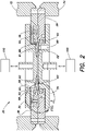
FIG. 2 is a cross-sectional view of an exemplary rheometer according to one illustrative embodiment; and -
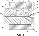
FIG. 3 is an enlarged view of a portion of the rheometer ofFIG. 2 encircled by line 3. - Rheometers are typically used to determine various properties of a viscoelastic material, such as rubber, vulcanizable rubbers, polymers, plastics, thermoplastics, or other material. These instruments may be commonly referred to as Moving Die Rheometers (MDR), Rubber Process Analyzers (RPA), Oscillating Disk Rheometers (ODR) and/or Mooney Viscometers. These instruments may apply a rotational shear force to a material sample and may measure the resulting torque on the sample. Information about the material may be derived from the measured torque on the sample. The material sample to be tested may be enclosed within a chamber formed between two opposing rheometer dies and the rotational shear force may be applied to the material sample by rotating one die while the other die remains stationary. It should be appreciated that the term "rheometer" refers to any rheological instrument used to measure a process characteristic of a viscoelastic material, including the devices listed above.
- As discussed above, a rheometer may be configured with dies forming the upper and lower portions of the sample-holding chamber. In a conventional rheometer, each die is a circular disc rotatable in a co-axial cylindrical housing surrounding the die. An annular seal of a heat-resistant elastomeric material is seated in a groove in an axially-extending face of the die housing and in contact with an axially-extending face of the die. Such seals have been required to maintain a constant pressure in the sample-holding chamber during the test. However, the seal is subjected to constant wear due to contact with the die during relative movement between the housing and the die. In addition, contact between the sample and the seal can also increase the wear on the seal. As a result, such seals can wear out quickly, requiring frequent recalibration of the instrument and replacement of the seal.
- For example,
FIG. 1 illustrates an exemplaryconventional rheometer 10. An upper die assembly comprisesupper housing 21 andupper die 11.Upper housing 21, which includesupper sealing plate 15, surroundsupper die 11.Upper seal 13 is seated in a groove in the axially-extending face ofupper sealing plate 15 and is in contact withupper die 11 at an inner annular face of the seal. A lower die assembly compriseslower housing 22 andlower die 12 also at an inner annular surface of the seal.Housing 22, which includeslower sealing plate 16, surroundslower die 12. Lower seal 14 is seated in a groove in the axially-extending face oflower sealing plate 16 and is in contact withlower die 12. Upper die 11 connects to atorque transducer 26 via fasteners around the periphery ofupper die 11. Lower die 12 connects to adrive mechanism 25 via fasteners around the periphery oflower die 12.Upper seal 13, which is seated inupper sealing plate 15 and around theupper die 11, imparts a drag on the movement of theupper die 11. The amount of drag changes when the physical properties of the seal change due to extreme temperatures and substantial wear due to contact with the sample present in the chamber. Such changes in drag may distort torque measurements at the torque transducer and lead to inaccurate results. - There have been several attempts to avoid such a seal arrangement. For example, according to one approach, the seal between the die and die housing is removed and the sample-holding chamber is left open to atmospheric pressure. The inventors have appreciated that, in such an arrangement, the sample-holding chamber is no longer pressurized, allowing air bubbles to form within the sample, thereby giving rise to measurement distortion and inaccurate results.
- According to another approach, the elastomeric seal between the die and die housing is removed and a film is placed between the sample and the die to bridge a gap between the die and the die housing. The inventors have appreciated that, in such an arrangement, the film adheres to the die housing and the upper die and gives rise to a significant drag force between the die and the die housing via the film that creates measurement distortion and inaccurate results. Stiffer test materials also contribute to measurement distortion by creating an additional drag force between the upper die and the die housing.
- According to another approach, the heat-resistant elastomeric seal is replaced with a bearing material. The inventors have appreciated that, because bearing materials cannot handle temperature changes well, the use of bearing materials in a rheometer die assembly may cause gap size changes between the die and the die housing due to fluctuations in temperature during the testing process, resulting in issues with repeatability. In addition, the inventors have appreciated that it is difficult to manufacture such a device in a repeatable way in multiple rheometers.
- Aspects of the invention are directed to a die assembly which is configured to produce accurate and repeatable measurement while reducing the frequency of instrument recalibration and seal replacement. Also, this arrangement allows multiple rheometers to operate in a more repeatable manner.
- According to an aspect, the conventional elastomeric seal that contacts both the die and the die housing is eliminated while the pressure in the sample-holding chamber is maintained with a configuration that reduces or eliminates drag.
- In one embodiment, a die assembly includes a film and a backing element. The film bridges a gap between a die and its housing to maintain pressure in the sample-holding chamber while the presence of the backing element reduces or eliminates drag between the film and the die housing. In this manner, frequent instrument recalibration due to seal wearing is reduced due to the absence of the conventional seal, while the film maintains pressure in the sample-holding chamber. Maintaining pressure in the test chamber may be desirable for a variety of reasons, including reducing the likelihood of formation of air bubbles in the sample, as will be explained.
- As shown in
FIG. 2 ,rheometer 30 includes an upper die assembly which comprisesupper housing 72 andupper die 32.Upper housing 72, which includes anupper sealing plate 36, surroundsupper die 32. A lower die assembly compriseslower housing 74 andlower die 34.Lower housing 74, which includes alower sealing plate 38, surroundslower die 34. Opposing faces 61, 62 of dies 32, 34 are axially movable relative to one another between an open position and a closed position. Anannular seal 40 is seated in a groove in the axially-extending face oflower sealing plate 38 and is in contact withlower die 34. - As seen most clearly in
FIG. 3 , a small, substantiallycircumferential gap 58 separatesupper sealing plate 36 fromupper die 32. Accordingly, forces applied to upper die 32 are not transferred to theupper sealing plate 36. This allows atorque transducer 110 to accurately measure the torque applied to upper die 32 by the sample located between the upper and lower die 34 as thelower die 34 rotates. In some embodiments,gap 58 may be between 0.0127 to 0.02032 cm (0.005 to 0.008 inches). Any suitable gap size that does not cause leakage may be used, as this aspect is not limited in this regard. Alternatively or in addition, thegap 58 may also separate the upper die 32 from the retainingring 44 and/or thebacking element 42. - A
film 50 is positioned between the upper and lower die assemblies to bridge thisgap 58 between theupper sealing plate 36 and theupper die 32. The presence offilm 50 serves to seal sample-holdingchamber 66 from atmospheric pressure, allowing sample-holdingchamber 66 to remain pressurized during testing. Maintaining a pressurized sample-holdingchamber 66 helps to prevent formation of air bubbles that distort measurements. - Various polymer films having non-adhesive and thermal characteristics may be used for
film 50, for example aromatic polyesters, polyamides and polyimides. Certain mixed polyimide/polyamide or polyester ether ketone films can also be used, for example, 'Kapton' polyimide film. In addition, metallised polymer films may also be used, as well as certain metallic films or foils. In some embodiments, CHANGSHU HUACHIANG CH250 may be used. In some embodiments,DUPONT KAPTON 100 HN may be used. - In some embodiments, the film may have a tensile strength at break in the range 175-215 MPa in the machine direction and 225-275 MPa in the transverse direction, a yield stress in the range 85-105 MPa in both directions, and an elongation at break in the range 110-140% in the machine direction and 70-90% in the transverse direction. These values are determined by ASTM method D-882-83 carried out at 23 degrees Celsius, 50% relative humidity and a strain rate of 50% per min. In some embodiments, the film may have a tensile strength at break of 139 MPa in the machine direction and 120 MPa in the transverse direction, a yield stress of 69 MPa, and an elongation at break of 40%.
- Films of various thickness can be used. In some embodiments, the film has a thickness in the range of 15-50 micrometers. In some embodiments, the film has a thickness in the range of 20-25 micrometers. In some embodiments, the film has a thickness in the range of 15-100 micrometers. In some embodiments, the film has a thickness of 25 micrometers.
- The film may be sandwiched between the upper and lower die assemblies. In some cases, the film may be replaced after each test. In some embodiments, a first film is used to separate the sample from the upper die assembly, and a second film is used to separate the sample from the lower die assembly. In other embodiments, film is used to separate the sample from the upper die assembly, while film is not used to separate the sample from the lower die assembly.
- When a film is used to keep the sample-holding chamber pressurized, contact between the film and the die housing during testing creates drag that distorts measurements and leads to inaccurate results. In one embodiment, this drag between the film and the die housing is reduced by the presence of a backing element between the film and the die housing. To prevent contact between the film and the housing, a backing element cooperates with the housing such that the film interfaces with the backing element instead of with the housing.
- In one embodiment, as seen in
FIG. 2 , backingelement 42 is an annular member that cooperates withupper housing 72 and is seated in a groove inupper sealing plate 36. Theupper sealing plate 36 forms part ofupper housing 72. - As best seen in
FIG. 3 , backingelement 42 cooperates withupper sealing plate 36 of theupper die housing 72. When the upper and lower dies 32, 34 are in the closed position to form the sample-holdingchamber 66, backingelement 42 is positioned such that, with thefilm 50 removed, the portion of thebacking element 42 closest to the sample-holdingchamber 66 interfaces with the sample-holdingchamber 66. - With the
film 50 positioned between the upper and lower dies 32, 34, thebacking element 42 is positioned betweenfilm 50 and theupper sealing plate 36 of theupper die housing 72 in the area surrounding opposingface 61 ofupper die 32. Due to the presence ofbacking element 42, contact betweenfilm 50 andupper sealing plate 36 in the area surrounding opposingface 61 ofupper die 32 is reduced, and in some embodiments, eliminated, thereby reducing creation of drag forces betweenfilm 50 andupper sealing plate 36. Instead, film 50contacts backing element 42 when thefilm 50 moves relative to thebacking element 42 during testing. In some embodiments, thebacking element 42 may be situated to allow thefilm 50 to only come in contact with thebacking element 42 in the area surrounding the opposingface 61 ofupper die 32. - The
backing element 42 is spaced from the upper die to avoid wear of the backing element. In one embodiment, as best seen inFIG. 3 , backingelement 42 is spaced from upper die 32 bygap 58. During rotation of upper die 32 relative toupper sealing plate 36, backingelement 42 does not contactupper die 32. Due to its isolation fromupper die 32, backingelement 42 is not subject to the frictional forces that may wear away conventional rheometer seals. Furthermore,film 50 separates thebacking element 42 from the sample-holdingchamber 66 such that sample does not contact thebacking element 42 during the testing process. - Backing
element 42 may cooperate withupper sealing plate 36 in any suitable arrangement. In some embodiments, backingelement 42 may remain disposed against upper sealingplate 36 due to an interference fit ofbacking element 42 within acircumferential groove 55 in theupper sealing plate 36. Alternatively or in addition, other suitable retaining arrangements may be used to maintain contact between thebacking element 42 with theupper sealing plate 36. In some embodiments, a retainer helps to maintain contact between the backing element and the housing. The retainer exerts a retaining force upon the backing element to prevent movement of the backing element relative to the die housing. In the embodiment shown inFIG. 2 , retainingring 44 cooperates with theupper die housing 72 to exert a retaining force upon backingelement 42 by compressingbacking element 42 between retainingring 44 andupper sealing plate 36. As shown inFIGS. 2-3 , a portion ofbacking element 42 is located between retainingring 44 andupper sealing plate 36. - The retaining
ring 44 may be secured toupper sealing plate 36 in any suitable way. Afastener 46 may be used to attach retainingring 44 to theupper sealing plate 36. Any suitable fastener may be used to attach retainingring 44 to theupper sealing plate 36, such as a screw or other suitable hardware. In some embodiments, retainingring 44 may attach toupper sealing plate 36 without the use of fasteners, for example, via an interference fit, a dovetail joint, or other suitable arrangements. - In some embodiments, to achieve a compact and/or streamlined configuration, retaining
ring 44 may cooperate with theupper sealing plate 36 to form a single unitary body or shape. Retainingring 44 may cooperate with theupper sealing plate 36 such that thesurface 45 of the retainingring 44 is flush with thesurface 37 of theupper sealing plate 36, and thus retainingring 44 andupper sealing plate 36 combine to form a single unitary shape. In some embodiments, the upper sealing plate may be integrally formed with a retainer such that the upper sealing plate and retainer form a single component. - Of course, it should be appreciated that a
backing element 42 may cooperate withupper sealing plate 36 to maintain contact with theupper sealing plate 36 or to be otherwise disposed against upper sealingplate 36 by any suitable means, as this aspect is not limited in this regard. For example, thebacking element 42 may be held by upper sealingplate 36 by an interference fit alone. As another example, thebacking element 42 may be directly attached toupper sealing plate 36 by fasteners. Alternatively or in addition, backingelement 42 may be simply seated within a recess or groove inupper sealing plate 36 and remain disposed against upper sealingplate 36 without an interference fit. In still other embodiments, the backing element may be adhered in place. -
FIGS. 2 and3 depict a single backing element, film and retainer arrangement only at the die that is coupled to the torque transducer. Alternatively or in addition, the same or similar backing element, film and retainer arrangement may be used at the die that is coupled to the drive mechanism. For example, in one embodiment, theannular seal 40 atlower die 34 shown inFIGS. 2-3 is replaced by a backing ring, film and retainer arrangement similar to that used atupper die 32. - The material of
backing element 42 may be chosen such that it may flex along with the material in the sample chamber. The backing element may be made from any suitable elastomer. - The material of
backing element 42 may also be chosen such that sliding contact betweenfilm 50 andbacking element 42 creates less drag force than sliding contact betweenfilm 50 andupper sealing plate 36. The backing element is made of a material of sufficient lubricity to avoid adherence between it and the film. For example, the backing element may be made of polytetrafluoroethylene (PTFE), or any suitable elastomer, such as a fluoroelastomer. In addition, the backing element may be made of other materials that can reduce drag such as graphite or bearing type materials. - Additional features of an exemplary rheometer are now discussed. The upper die assembly and lower die assembly are axially movable relative to one another between an open position and a closed position. To achieve the closed position shown in
FIG. 2 , the upper and lower die assemblies are moved toward one another such that the opposing faces 61 and 62 of dies 32, 34 define a sample-holdingchamber 66 for holding a material sample. The sample-holdingchamber 66 may have a predetermined shape and volume. When the upper and lower die assemblies are moved away from one another into the open position, the sample can be inserted or removed from between the upper and lower dies 32, 34. According to another embodiment, the sample may be injected into the rheometer. - As seen in
FIG. 2 , the opposing faces 61 and 62 of dies 32, 34 are in the form of shallow flat-topped cones (i.e., bioconical plates) havingradial grooves 63. Thus, a sample in the sample-holdingchamber 66 has a thin, flat circular portion in the middle, and an outer portion which increases in thickness radially outwards. It should be appreciated that opposing faces 61 and 62 may have other configurations, including a generally planar surface (i.e., parallel plates). The biconical plate configuration is typically used for rubber materials, while the flat plate configuration is typically used for either rubber, plastic materials or resin impregnated fiber. - To impart a shear force onto a sample held in sample-holding chamber, one die may move relative to the other die. In the illustrative embodiment of
FIG. 2 , theupper die 32 is stationary, while thelower die 34 is coupled to adrive mechanism 100 for rotation. It should be appreciated that in other embodiments, theupper die 32 may be configured for movement while thelower die 34 may be stationary, as the present invention is not limited in this respect. Adrive mechanism 100 is coupled to thelower die 34 in known fashion to impart movement of thelower die 34. It should be appreciated that various components may be used to generate die movement, as the present invention is not so limited. The applied rotational shear force created by the movingdie 34 may be oscillatory or continuous and may have a predetermined amplitude and frequency. According to one embodiment, the applied shear force is at an amplitude of oscillation within a range of approximately +/- 0.1° arc to +/- 180° arc, with a frequency of oscillation within a range of approximately 0.001 Hz to 50 Hz. However, it should be appreciated that the present invention is not limited to the application of a particular type of shear force on the material sample. It is contemplated that other amplitude and frequency ranges may be utilized, as the present invention is not so limited. In one embodiment, the lower die may rotate continuously in one direction. In another embodiment, a stress relaxation test may be used, in which the lower die undergoes a brief rapid movement in one direction and then stops. To measure the torque on the sample held in sample-holding chamber, the rheometer is coupled to a torque transducer. In the illustrative embodiment ofFIG. 2 , atorque transducer 110 is coupled to the stationaryupper die 32 in known fashion. In another embodiment, thetorque transducer 110 may be coupled to other suitable components and/or at other suitable locations that will experience a measureable strain or torque, as the present aspect is not so limited. It should be appreciated that various types of torque transducers or other suitable devices and/or arrangements may be used to measure the torque on the sample, as the present aspect is not limited in this respect. - The measured resulting torque on the sample may be an indication of the particular response of the sample material to the particular applied shear force. Process characteristics of the sample material may be derived from the measured torque. For example, the elastic torque, viscous or loss torque and the modulus of the sample material may be determined based upon calculations with the measured complex torque on the sample, the frequency and amplitude of the rotation, and the dimensions of the dies. Any suitable methodology may be employed, and thus are not described in detail in the present application.
- Process characteristics of a material may change significantly by varying temperature, frequency and/or strain. Testing at several different frequencies, strains and temperatures may be necessary to adequately characterize a material sample. In one embodiment, the desired frequency, strain, and temperature for a particular test may be programmed into a computer which interfaces with the rheometer.
- In some test arrangements, the material sample may be heated so that the sample conforms to the rheometer dies. The sample may also be heated to test various process characteristics of the material at certain temperatures. Heaters and temperature sensors may be provided to control the temperature of the sample. In general, the softer the material, the lower the torque on the sample. However, as a sample cools from a molten or semi-molten state to a more solid state, the harder samples increases the measured torque. As illustrated in
FIG. 2 ,temperature sensors 90 may be provided on one or more dies to measure and assist in controlling the temperature of the sample. A sensor may be positioned closer to the surface of the die which contacts the sample to more accurately measure the temperature of the sample. - Other features of a conventional rheometer may be used in connection with the rheometer and sealless rheometer die assembly discussed herein. Such additional features will be readily apparent to one of skill in the art.
Claims (14)
- A rheometer (30) for measuring properties of a sample material, comprising:a first die assembly comprising a first die (32) and a first sealing plate (36);a gap (58) between the first die (32) and the first sealing plate (36);a second die assembly comprising a second die (34) and a second sealing plate (38), the first and second dies (32, 34) forming a sample-holding chamber (66); anda backing element (42) cooperating with the first sealing plate (36), wherein a portion of the backing element (42) interfaces with the sample-holding chamber (66),wherein
at least a portion of the backing element (42) comprises polytetrafluoroethylene, an elastomer or graphite,wherein:
the first and second die assemblies are arranged to accept a film (50) to be positioned between the first and second dies (32, 34)to bridge the gap (58) between the first die (32) and the first sealing plate (36), and when the film (50) is held between the dies (32, 34), the backing element (42) is spaced from the first die (32) while said backing element (42) contacts the film (50) with the film (50) separating the backing element (42) from the sample-holding chamber (66). - The rheometer (30) of claim 1, further comprising a retainer (44) cooperating with the first sealing plate (36) to prevent movement of the backing element (42) relative to the first sealing plate (36).
- The rheometer (30) of claim 2, wherein at least a portion of the backing element (42) is positioned between the retainer (44) and the first sealing plate (36).
- The rheometer (30) of claim 2, wherein a portion of the retainer (44) is positioned between the backing element (42) and the first die (32).
- The rheometer (30) of claim 1, further comprising a drive mechanism (100) coupled to the second die (34), the drive mechanism (100) constructed and arranged to rotate one of the first or second dies (32, 34) relative to the other die (32, 34).
- The rheometer (30) of claim 1, further comprising a seal (40) positioned between the second die (34) and the second sealing plate (38).
- The rheometer (30) of claim 1, wherein the first and second die assemblies have an open and a closed position.
- The rheometer (30) of claim 1, wherein at least one of the first and second dies (32, 34) is rotatable relative to the other of the first and second dies (32, 34).
- The rheometer (30) of claim 1, further comprising a torque transducer (110) coupled to the first die (32) constructed and arranged to measure the torque on a sample in the sample-holding chamber (66).
- The rheometer (30) of claim 1, further comprising a film (50) positioned between the first and second dies (32, 34) to bridge the gap (58) between the first die (32) and the first sealing plate (36).
- The rheometer (30) of claim 10, wherein the film (50) comprises a polyimide material.
- The rheometer (30) of claim 10, wherein the film (50) has a thickness between 15 micrometers to 50 micrometers.
- The rheometer (30) of claim 1, further comprising:a second backing element cooperating with the second sealing plate (38); anda second gap between the second die (34) and the second sealing plate (38);a second film positioned between the first and second dies (32, 34) to bridge the second gap between the second die (34) and the second sealing plate (38),wherein, when the first and second die assemblies are in the closed position, the second backing element is spaced from the second die (34), and the second film separates the second backing element from the sample-holding chamber (66).
- A method for measuring properties of a sample material using a rheometer (30) comprising a first die assembly comprising a first die (32) and a first sealing plate (36), a backing element (42) that cooperates with the first sealing plate (36), and a second die assembly comprising a second die (34) and a second sealing plate (38), the first and second dies (32, 34) forming a sample-holding chamber (66), wherein the method comprises:placing a sample in the sample-holding chamber (66);placing a film (50) between the sample and the first die assembly to bridge a gap (58) between the first die (32) and the first sealing plate (36) such that, when the first and second die assemblies are in the closed position, the backing element (42) is spaced from the first die (32), and the film (50) separates the backing element (42) from the sample-holding chamber (66) .
Applications Claiming Priority (2)
| Application Number | Priority Date | Filing Date | Title |
|---|---|---|---|
| US13/828,201 US9091626B2 (en) | 2013-03-14 | 2013-03-14 | Sealless rheometer die assembly |
| PCT/US2014/024225 WO2014159569A1 (en) | 2013-03-14 | 2014-03-12 | Sealless rheometer die assembly |
Publications (2)
| Publication Number | Publication Date |
|---|---|
| EP2972199A1 EP2972199A1 (en) | 2016-01-20 |
| EP2972199B1 true EP2972199B1 (en) | 2022-10-19 |
Family
ID=50543670
Family Applications (1)
| Application Number | Title | Priority Date | Filing Date |
|---|---|---|---|
| EP14719145.6A Active EP2972199B1 (en) | 2013-03-14 | 2014-03-12 | Sealless rheometer die assembly |
Country Status (6)
| Country | Link |
|---|---|
| US (1) | US9091626B2 (en) |
| EP (1) | EP2972199B1 (en) |
| JP (1) | JP6169243B2 (en) |
| CN (1) | CN104364632B (en) |
| HK (1) | HK1207417A1 (en) |
| WO (1) | WO2014159569A1 (en) |
Families Citing this family (6)
| Publication number | Priority date | Publication date | Assignee | Title |
|---|---|---|---|---|
| WO2016060928A1 (en) * | 2014-10-14 | 2016-04-21 | Alpha Technologies Services Llc | Rheometer system with decoupled cross-head |
| US10416058B2 (en) * | 2014-10-14 | 2019-09-17 | Alpha Technologies Services Llc | Variable eccentric cam rheometer system |
| CN104897519A (en) * | 2015-06-05 | 2015-09-09 | 福建工程学院 | Shear extrusion rheometer |
| CN108139308A (en) | 2015-09-30 | 2018-06-08 | 阿尔法科技服务有限责任公司 | Torsional Rheometers That Maintain More Uniform Chamber Pressures |
| US10837874B2 (en) * | 2016-03-21 | 2020-11-17 | Abaco Drilling Technologies, LLC | Stall simulator for PDM performance testing device |
| TWI722319B (en) * | 2018-09-18 | 2021-03-21 | 日月光半導體製造股份有限公司 | Mold chase for semiconductor package |
Family Cites Families (13)
| Publication number | Priority date | Publication date | Assignee | Title |
|---|---|---|---|---|
| US4343190A (en) * | 1980-06-02 | 1982-08-10 | Monsanto Company | Moving die rheometer, method of testing materials therewith, and die for use therein |
| US4337646A (en) * | 1980-06-11 | 1982-07-06 | Fraleigh M Foster | Oscillating rheometer die set |
| JPS5757952A (en) * | 1980-09-20 | 1982-04-07 | Japan Synthetic Rubber Co Ltd | Method and device for converting rotary motion into rotary vibrating motion |
| US4421424A (en) * | 1981-01-29 | 1983-12-20 | Monsanto Europe S.A. | Instrument and method for control testing of vulcanized rubber |
| US4552025A (en) * | 1983-09-06 | 1985-11-12 | Monsanto Company | Multifunction processability testing method and apparatus |
| GB8921241D0 (en) * | 1989-09-20 | 1989-11-08 | Monsanto Plc | Testing of viscoelastic materials |
| GB9108961D0 (en) * | 1991-04-26 | 1991-06-12 | Monsanto Plc | Instrument and method for viscoelasticity measurements |
| US6164818A (en) | 1999-01-21 | 2000-12-26 | Alpha Technologies | Method and apparatus for measuring viscous heating of viscoelastic materials |
| JP2000230895A (en) * | 1999-02-08 | 2000-08-22 | Nichigo Shoji Co Ltd | Device and method for measuring curing characteristic |
| US6336357B1 (en) * | 1999-03-15 | 2002-01-08 | Henry Pawlowski | Method and apparatus for sealing test materials |
| WO2001022053A1 (en) | 1999-09-20 | 2001-03-29 | Alpha Technologies, U.S. L.P. | Sealless die assembly for viscoelastic measuring apparatus |
| US20070220990A1 (en) | 2006-03-23 | 2007-09-27 | Putman John B | Material testing apparatus with selectively sealed and unsealed dies |
| US7475592B2 (en) | 2006-06-19 | 2009-01-13 | Alpha Technologies Services Lcc | Rheometer |
-
2013
- 2013-03-14 US US13/828,201 patent/US9091626B2/en active Active
-
2014
- 2014-03-12 WO PCT/US2014/024225 patent/WO2014159569A1/en not_active Ceased
- 2014-03-12 EP EP14719145.6A patent/EP2972199B1/en active Active
- 2014-03-12 CN CN201480001293.3A patent/CN104364632B/en active Active
- 2014-03-12 HK HK15107970.2A patent/HK1207417A1/en unknown
- 2014-03-12 JP JP2016501442A patent/JP6169243B2/en active Active
Also Published As
| Publication number | Publication date |
|---|---|
| JP2016511421A (en) | 2016-04-14 |
| HK1207417A1 (en) | 2016-01-29 |
| US20140260558A1 (en) | 2014-09-18 |
| JP6169243B2 (en) | 2017-07-26 |
| CN104364632B (en) | 2016-12-14 |
| EP2972199A1 (en) | 2016-01-20 |
| US9091626B2 (en) | 2015-07-28 |
| WO2014159569A1 (en) | 2014-10-02 |
| CN104364632A (en) | 2015-02-18 |
Similar Documents
| Publication | Publication Date | Title |
|---|---|---|
| US9091626B2 (en) | Sealless rheometer die assembly | |
| EP0041375B1 (en) | Moving die rheometer and die for use therein | |
| EP2069753B1 (en) | A rheometer | |
| CA1215854A (en) | Multifunction processability testing method and apparatus | |
| CN110501373A (en) | The method of accurate measurement glass transition temperature of polymer | |
| JP3224956B2 (en) | Method and apparatus for measuring viscoelasticity | |
| CN103499639B (en) | A kind of online characterizing method of sulfidation ultrasonic wave | |
| US6588254B1 (en) | Rotary rheometer | |
| US20030183016A1 (en) | Rheometer | |
| US10557782B2 (en) | Pressure cell for rheological experiments under oscillatory shear and pressure | |
| US9366611B2 (en) | Apparatus for mapping liner wear of a bearing | |
| US4571989A (en) | Method and apparatus for measuring rheological properties of fluid | |
| EP0511190B1 (en) | Instrument and method for viscoelasticity measurements | |
| US6336357B1 (en) | Method and apparatus for sealing test materials | |
| JP4032021B2 (en) | Vulcanization test equipment | |
| WO2001022053A1 (en) | Sealless die assembly for viscoelastic measuring apparatus | |
| JP2773952B2 (en) | Viscoelastic body stress measuring device | |
| EP3356789B1 (en) | Torsional rheometer that maintains a more uniform cavity pressure | |
| CN222748136U (en) | Mold cavity temperature test probe for rotor-free vulcanizer | |
| SU972295A1 (en) | Device for testing packing of polymer materials | |
| JPH07225182A (en) | Stress measuring apparatus for viscoelastic body | |
| CZ25617U1 (en) | Device for operational measurement of elastomer mechanical properties | |
| JPH0772062A (en) | Method and apparatus for measuring physical property of foaming resin |
Legal Events
| Date | Code | Title | Description |
|---|---|---|---|
| PUAI | Public reference made under article 153(3) epc to a published international application that has entered the european phase |
Free format text: ORIGINAL CODE: 0009012 |
|
| 17P | Request for examination filed |
Effective date: 20150916 |
|
| AK | Designated contracting states |
Kind code of ref document: A1 Designated state(s): AL AT BE BG CH CY CZ DE DK EE ES FI FR GB GR HR HU IE IS IT LI LT LU LV MC MK MT NL NO PL PT RO RS SE SI SK SM TR |
|
| AX | Request for extension of the european patent |
Extension state: BA ME |
|
| DAX | Request for extension of the european patent (deleted) | ||
| STAA | Information on the status of an ep patent application or granted ep patent |
Free format text: STATUS: EXAMINATION IS IN PROGRESS |
|
| 17Q | First examination report despatched |
Effective date: 20211112 |
|
| GRAP | Despatch of communication of intention to grant a patent |
Free format text: ORIGINAL CODE: EPIDOSNIGR1 |
|
| STAA | Information on the status of an ep patent application or granted ep patent |
Free format text: STATUS: GRANT OF PATENT IS INTENDED |
|
| INTG | Intention to grant announced |
Effective date: 20220429 |
|
| GRAS | Grant fee paid |
Free format text: ORIGINAL CODE: EPIDOSNIGR3 |
|
| GRAA | (expected) grant |
Free format text: ORIGINAL CODE: 0009210 |
|
| STAA | Information on the status of an ep patent application or granted ep patent |
Free format text: STATUS: THE PATENT HAS BEEN GRANTED |
|
| AK | Designated contracting states |
Kind code of ref document: B1 Designated state(s): AL AT BE BG CH CY CZ DE DK EE ES FI FR GB GR HR HU IE IS IT LI LT LU LV MC MK MT NL NO PL PT RO RS SE SI SK SM TR |
|
| REG | Reference to a national code |
Ref country code: GB Ref legal event code: FG4D |
|
| REG | Reference to a national code |
Ref country code: CH Ref legal event code: EP |
|
| REG | Reference to a national code |
Ref country code: IE Ref legal event code: FG4D |
|
| REG | Reference to a national code |
Ref country code: DE Ref legal event code: R096 Ref document number: 602014085252 Country of ref document: DE |
|
| REG | Reference to a national code |
Ref country code: AT Ref legal event code: REF Ref document number: 1525838 Country of ref document: AT Kind code of ref document: T Effective date: 20221115 |
|
| REG | Reference to a national code |
Ref country code: LT Ref legal event code: MG9D |
|
| REG | Reference to a national code |
Ref country code: NL Ref legal event code: MP Effective date: 20221019 |
|
| REG | Reference to a national code |
Ref country code: AT Ref legal event code: MK05 Ref document number: 1525838 Country of ref document: AT Kind code of ref document: T Effective date: 20221019 |
|
| PG25 | Lapsed in a contracting state [announced via postgrant information from national office to epo] |
Ref country code: NL Free format text: LAPSE BECAUSE OF FAILURE TO SUBMIT A TRANSLATION OF THE DESCRIPTION OR TO PAY THE FEE WITHIN THE PRESCRIBED TIME-LIMIT Effective date: 20221019 |
|
| PG25 | Lapsed in a contracting state [announced via postgrant information from national office to epo] |
Ref country code: SE Free format text: LAPSE BECAUSE OF FAILURE TO SUBMIT A TRANSLATION OF THE DESCRIPTION OR TO PAY THE FEE WITHIN THE PRESCRIBED TIME-LIMIT Effective date: 20221019 Ref country code: PT Free format text: LAPSE BECAUSE OF FAILURE TO SUBMIT A TRANSLATION OF THE DESCRIPTION OR TO PAY THE FEE WITHIN THE PRESCRIBED TIME-LIMIT Effective date: 20230220 Ref country code: NO Free format text: LAPSE BECAUSE OF FAILURE TO SUBMIT A TRANSLATION OF THE DESCRIPTION OR TO PAY THE FEE WITHIN THE PRESCRIBED TIME-LIMIT Effective date: 20230119 Ref country code: LT Free format text: LAPSE BECAUSE OF FAILURE TO SUBMIT A TRANSLATION OF THE DESCRIPTION OR TO PAY THE FEE WITHIN THE PRESCRIBED TIME-LIMIT Effective date: 20221019 Ref country code: FI Free format text: LAPSE BECAUSE OF FAILURE TO SUBMIT A TRANSLATION OF THE DESCRIPTION OR TO PAY THE FEE WITHIN THE PRESCRIBED TIME-LIMIT Effective date: 20221019 Ref country code: ES Free format text: LAPSE BECAUSE OF FAILURE TO SUBMIT A TRANSLATION OF THE DESCRIPTION OR TO PAY THE FEE WITHIN THE PRESCRIBED TIME-LIMIT Effective date: 20221019 Ref country code: AT Free format text: LAPSE BECAUSE OF FAILURE TO SUBMIT A TRANSLATION OF THE DESCRIPTION OR TO PAY THE FEE WITHIN THE PRESCRIBED TIME-LIMIT Effective date: 20221019 |
|
| PG25 | Lapsed in a contracting state [announced via postgrant information from national office to epo] |
Ref country code: RS Free format text: LAPSE BECAUSE OF FAILURE TO SUBMIT A TRANSLATION OF THE DESCRIPTION OR TO PAY THE FEE WITHIN THE PRESCRIBED TIME-LIMIT Effective date: 20221019 Ref country code: PL Free format text: LAPSE BECAUSE OF FAILURE TO SUBMIT A TRANSLATION OF THE DESCRIPTION OR TO PAY THE FEE WITHIN THE PRESCRIBED TIME-LIMIT Effective date: 20221019 Ref country code: LV Free format text: LAPSE BECAUSE OF FAILURE TO SUBMIT A TRANSLATION OF THE DESCRIPTION OR TO PAY THE FEE WITHIN THE PRESCRIBED TIME-LIMIT Effective date: 20221019 Ref country code: IS Free format text: LAPSE BECAUSE OF FAILURE TO SUBMIT A TRANSLATION OF THE DESCRIPTION OR TO PAY THE FEE WITHIN THE PRESCRIBED TIME-LIMIT Effective date: 20230219 Ref country code: HR Free format text: LAPSE BECAUSE OF FAILURE TO SUBMIT A TRANSLATION OF THE DESCRIPTION OR TO PAY THE FEE WITHIN THE PRESCRIBED TIME-LIMIT Effective date: 20221019 Ref country code: GR Free format text: LAPSE BECAUSE OF FAILURE TO SUBMIT A TRANSLATION OF THE DESCRIPTION OR TO PAY THE FEE WITHIN THE PRESCRIBED TIME-LIMIT Effective date: 20230120 |
|
| P01 | Opt-out of the competence of the unified patent court (upc) registered |
Effective date: 20230527 |
|
| REG | Reference to a national code |
Ref country code: DE Ref legal event code: R097 Ref document number: 602014085252 Country of ref document: DE |
|
| PG25 | Lapsed in a contracting state [announced via postgrant information from national office to epo] |
Ref country code: SM Free format text: LAPSE BECAUSE OF FAILURE TO SUBMIT A TRANSLATION OF THE DESCRIPTION OR TO PAY THE FEE WITHIN THE PRESCRIBED TIME-LIMIT Effective date: 20221019 Ref country code: RO Free format text: LAPSE BECAUSE OF FAILURE TO SUBMIT A TRANSLATION OF THE DESCRIPTION OR TO PAY THE FEE WITHIN THE PRESCRIBED TIME-LIMIT Effective date: 20221019 Ref country code: EE Free format text: LAPSE BECAUSE OF FAILURE TO SUBMIT A TRANSLATION OF THE DESCRIPTION OR TO PAY THE FEE WITHIN THE PRESCRIBED TIME-LIMIT Effective date: 20221019 Ref country code: DK Free format text: LAPSE BECAUSE OF FAILURE TO SUBMIT A TRANSLATION OF THE DESCRIPTION OR TO PAY THE FEE WITHIN THE PRESCRIBED TIME-LIMIT Effective date: 20221019 Ref country code: CZ Free format text: LAPSE BECAUSE OF FAILURE TO SUBMIT A TRANSLATION OF THE DESCRIPTION OR TO PAY THE FEE WITHIN THE PRESCRIBED TIME-LIMIT Effective date: 20221019 |
|
| PLBE | No opposition filed within time limit |
Free format text: ORIGINAL CODE: 0009261 |
|
| STAA | Information on the status of an ep patent application or granted ep patent |
Free format text: STATUS: NO OPPOSITION FILED WITHIN TIME LIMIT |
|
| PG25 | Lapsed in a contracting state [announced via postgrant information from national office to epo] |
Ref country code: SK Free format text: LAPSE BECAUSE OF FAILURE TO SUBMIT A TRANSLATION OF THE DESCRIPTION OR TO PAY THE FEE WITHIN THE PRESCRIBED TIME-LIMIT Effective date: 20221019 Ref country code: AL Free format text: LAPSE BECAUSE OF FAILURE TO SUBMIT A TRANSLATION OF THE DESCRIPTION OR TO PAY THE FEE WITHIN THE PRESCRIBED TIME-LIMIT Effective date: 20221019 |
|
| 26N | No opposition filed |
Effective date: 20230720 |
|
| PG25 | Lapsed in a contracting state [announced via postgrant information from national office to epo] |
Ref country code: MC Free format text: LAPSE BECAUSE OF FAILURE TO SUBMIT A TRANSLATION OF THE DESCRIPTION OR TO PAY THE FEE WITHIN THE PRESCRIBED TIME-LIMIT Effective date: 20221019 |
|
| REG | Reference to a national code |
Ref country code: CH Ref legal event code: PL |
|
| PG25 | Lapsed in a contracting state [announced via postgrant information from national office to epo] |
Ref country code: SI Free format text: LAPSE BECAUSE OF FAILURE TO SUBMIT A TRANSLATION OF THE DESCRIPTION OR TO PAY THE FEE WITHIN THE PRESCRIBED TIME-LIMIT Effective date: 20221019 |
|
| REG | Reference to a national code |
Ref country code: BE Ref legal event code: MM Effective date: 20230331 |
|
| PG25 | Lapsed in a contracting state [announced via postgrant information from national office to epo] |
Ref country code: LU Free format text: LAPSE BECAUSE OF NON-PAYMENT OF DUE FEES Effective date: 20230312 |
|
| REG | Reference to a national code |
Ref country code: IE Ref legal event code: MM4A |
|
| PG25 | Lapsed in a contracting state [announced via postgrant information from national office to epo] |
Ref country code: LI Free format text: LAPSE BECAUSE OF NON-PAYMENT OF DUE FEES Effective date: 20230331 Ref country code: IE Free format text: LAPSE BECAUSE OF NON-PAYMENT OF DUE FEES Effective date: 20230312 Ref country code: CH Free format text: LAPSE BECAUSE OF NON-PAYMENT OF DUE FEES Effective date: 20230331 |
|
| PG25 | Lapsed in a contracting state [announced via postgrant information from national office to epo] |
Ref country code: BE Free format text: LAPSE BECAUSE OF NON-PAYMENT OF DUE FEES Effective date: 20230331 |
|
| PG25 | Lapsed in a contracting state [announced via postgrant information from national office to epo] |
Ref country code: BG Free format text: LAPSE BECAUSE OF FAILURE TO SUBMIT A TRANSLATION OF THE DESCRIPTION OR TO PAY THE FEE WITHIN THE PRESCRIBED TIME-LIMIT Effective date: 20221019 |
|
| PG25 | Lapsed in a contracting state [announced via postgrant information from national office to epo] |
Ref country code: BG Free format text: LAPSE BECAUSE OF FAILURE TO SUBMIT A TRANSLATION OF THE DESCRIPTION OR TO PAY THE FEE WITHIN THE PRESCRIBED TIME-LIMIT Effective date: 20221019 |
|
| PGFP | Annual fee paid to national office [announced via postgrant information from national office to epo] |
Ref country code: IT Payment date: 20250331 Year of fee payment: 12 |
|
| PG25 | Lapsed in a contracting state [announced via postgrant information from national office to epo] |
Ref country code: CY Free format text: LAPSE BECAUSE OF FAILURE TO SUBMIT A TRANSLATION OF THE DESCRIPTION OR TO PAY THE FEE WITHIN THE PRESCRIBED TIME-LIMIT; INVALID AB INITIO Effective date: 20140312 |
|
| PG25 | Lapsed in a contracting state [announced via postgrant information from national office to epo] |
Ref country code: HU Free format text: LAPSE BECAUSE OF FAILURE TO SUBMIT A TRANSLATION OF THE DESCRIPTION OR TO PAY THE FEE WITHIN THE PRESCRIBED TIME-LIMIT; INVALID AB INITIO Effective date: 20140312 |
|
| PG25 | Lapsed in a contracting state [announced via postgrant information from national office to epo] |
Ref country code: TR Free format text: LAPSE BECAUSE OF FAILURE TO SUBMIT A TRANSLATION OF THE DESCRIPTION OR TO PAY THE FEE WITHIN THE PRESCRIBED TIME-LIMIT Effective date: 20221019 |
|
| PGFP | Annual fee paid to national office [announced via postgrant information from national office to epo] |
Ref country code: GB Payment date: 20260317 Year of fee payment: 13 |
|
| PGFP | Annual fee paid to national office [announced via postgrant information from national office to epo] |
Ref country code: DE Payment date: 20260320 Year of fee payment: 13 |
|
| PGFP | Annual fee paid to national office [announced via postgrant information from national office to epo] |
Ref country code: FR Payment date: 20260324 Year of fee payment: 13 |