EP2971830B1 - Bi-directional overrunning clutch having split roll cage - Google Patents
Bi-directional overrunning clutch having split roll cage Download PDFInfo
- Publication number
- EP2971830B1 EP2971830B1 EP13878268.5A EP13878268A EP2971830B1 EP 2971830 B1 EP2971830 B1 EP 2971830B1 EP 13878268 A EP13878268 A EP 13878268A EP 2971830 B1 EP2971830 B1 EP 2971830B1
- Authority
- EP
- European Patent Office
- Prior art keywords
- hub
- roll cage
- housing
- coupler
- rollers
- Prior art date
- Legal status (The legal status is an assumption and is not a legal conclusion. Google has not performed a legal analysis and makes no representation as to the accuracy of the status listed.)
- Active
Links
Images






Classifications
-
- F—MECHANICAL ENGINEERING; LIGHTING; HEATING; WEAPONS; BLASTING
- F16—ENGINEERING ELEMENTS AND UNITS; GENERAL MEASURES FOR PRODUCING AND MAINTAINING EFFECTIVE FUNCTIONING OF MACHINES OR INSTALLATIONS; THERMAL INSULATION IN GENERAL
- F16D—COUPLINGS FOR TRANSMITTING ROTATION; CLUTCHES; BRAKES
- F16D41/00—Freewheels or freewheel clutches
- F16D41/06—Freewheels or freewheel clutches with intermediate wedging coupling members between an inner and an outer surface
- F16D41/064—Freewheels or freewheel clutches with intermediate wedging coupling members between an inner and an outer surface the intermediate members wedging by rolling and having a circular cross-section, e.g. balls
- F16D41/066—Freewheels or freewheel clutches with intermediate wedging coupling members between an inner and an outer surface the intermediate members wedging by rolling and having a circular cross-section, e.g. balls all members having the same size and only one of the two surfaces being cylindrical
- F16D41/067—Freewheels or freewheel clutches with intermediate wedging coupling members between an inner and an outer surface the intermediate members wedging by rolling and having a circular cross-section, e.g. balls all members having the same size and only one of the two surfaces being cylindrical and the members being distributed by a separate cage encircling the axis of rotation
-
- F—MECHANICAL ENGINEERING; LIGHTING; HEATING; WEAPONS; BLASTING
- F16—ENGINEERING ELEMENTS AND UNITS; GENERAL MEASURES FOR PRODUCING AND MAINTAINING EFFECTIVE FUNCTIONING OF MACHINES OR INSTALLATIONS; THERMAL INSULATION IN GENERAL
- F16D—COUPLINGS FOR TRANSMITTING ROTATION; CLUTCHES; BRAKES
- F16D47/00—Systems of clutches, or clutches and couplings, comprising devices of types grouped under at least two of the following sets of groups: F16D1/00 - F16D9/00, F16D11/00 - F16D23/00, F16D25/00 - F16D29/00, F16D31/00 - F16D39/00, F16D41/00 - F16D45/00
- F16D47/04—Systems of clutches, or clutches and couplings, comprising devices of types grouped under at least two of the following sets of groups: F16D1/00 - F16D9/00, F16D11/00 - F16D23/00, F16D25/00 - F16D29/00, F16D31/00 - F16D39/00, F16D41/00 - F16D45/00 of which at least one is a freewheel
-
- F—MECHANICAL ENGINEERING; LIGHTING; HEATING; WEAPONS; BLASTING
- F16—ENGINEERING ELEMENTS AND UNITS; GENERAL MEASURES FOR PRODUCING AND MAINTAINING EFFECTIVE FUNCTIONING OF MACHINES OR INSTALLATIONS; THERMAL INSULATION IN GENERAL
- F16D—COUPLINGS FOR TRANSMITTING ROTATION; CLUTCHES; BRAKES
- F16D21/00—Systems comprising a plurality of actuated clutches
- F16D21/08—Serially-arranged clutches interconnecting two shafts only when all the clutches are engaged
-
- F—MECHANICAL ENGINEERING; LIGHTING; HEATING; WEAPONS; BLASTING
- F16—ENGINEERING ELEMENTS AND UNITS; GENERAL MEASURES FOR PRODUCING AND MAINTAINING EFFECTIVE FUNCTIONING OF MACHINES OR INSTALLATIONS; THERMAL INSULATION IN GENERAL
- F16H—GEARING
- F16H48/00—Differential gearings
- F16H48/12—Differential gearings without gears having orbital motion
- F16H48/16—Differential gearings without gears having orbital motion with freewheels
Definitions
- the invention relates to a clutch system, and in particular a split roll cage configuration for a bi-directional overrunning clutch, for example, for use a primary drive axle.
- Bi-directional overrunning clutches are used to control torque transmission to the right and left segments of a primary drive shaft of a wheeled machine, to provide improved cornering ability and decreased wheel slippage as compared with solid shaft drives.
- One such overrunning clutch is described in U.S. Patent No. 6,722,484 , which is commonly owned with the present application, and which discloses the introduction of claim 1. Yet the need exists for simpler more reliable overrunning clutches for use in machinery such as snowblowers, lawnmowers, and all-terrain vehicles.
- a bi-directional overrunning clutch comprising
- the coupler includes a coupler hub with radially extending coupler teeth.
- Each coupler tooth has a length and width designed to position the coupler tooth in a corresponding slot in both cages.
- the width of the coupler tooth is less than the width of the associated slots so as to define a gap that permits one roll cage to index with respect to the other roll cage and the coupler tooth.
- the gap is preferably sized so that one roll cage can index so as to position its rollers to engage with one of either the forward or rear cam surfaces, while the coupler teeth prevent the other roll cage from indexing in the opposite direction thereby preventing its rollers from engaging with the other of either the forward or rear cam surfaces.
- a bi-directional overrunning clutch 10 is shown in Figs. 1-5A .
- the clutch 10 includes a housing 12 and a flange 14 affixed to the housing 12.
- the flange 14 is adapted to receive an input gear, sprocket, or other drive component that is engaged with an external drive mechanism for imparting rotational movement to the flange 14 and thus to the housing 12.
- the flange 14 includes bolt holes 16 for attaching the gear, it being understood that the gear may be attached to the flange 14 by any mechanical means known in the art, or may be formed as an integral part of the flange 14 or housing 12.
- the drive mechanism rotates the gear
- the flange 14 rotates, which in turn rotates the housing 12.
- the housing 12 includes a substantially cylindrical inner surface 80.
- the inner surface 80 includes a plurality of an inner cam surfaces 82 including forward and reverse cam surfaces 82a, 82b.
- either surface 82a, 82b may be interchangeably considered as a forward or a reverse cam surface.
- a pair of hubs 20 is located within the housing 12.
- the hubs 20 are substantially coaxially aligned with each other within the housing 12, and are each adapted to rotate about their common axis within the housing 12.
- the hubs 20 are not identical, but rather are mated to ensure their axial alignment.
- a first hub 20a includes a substantially cylindrical socket 90 while a second hub 20b includes a substantially cylindrical axial protrusion 92 adapted to be received into the socket 90.
- the first hub 20a is adapted to engage an end of a first shaft of a primary drive axle (not shown) and the second hub 20b is adapted to engage an end of a second shaft of the primary drive axle (not shown).
- Each hub 20 has a substantially cylindrical outer surface 24 having a diameter smaller than the diameter of the inner surface 80 of the housing 12, so that an annular space is formed between the outer surface 24 of the hubs 20 and the inner surface 80 of the housing 12.
- Each hub 20 preferably has an internal bore 26 into which a portion of a primary drive axle shaft is received.
- the internal bores 26 include splines to allow the shafts to move axially inward and outward with respect to the hubs 20 while ensuring that each shaft will rotate along with its respective hub 20.
- other mechanical connections between each shaft and its respective hub 20 may be used to ensure rotational coupling.
- the hubs 20 may be formed integrally with the primary drive shafts.
- each roller assembly 30 includes a roll cage 32 formed in a substantially cylindrical shape.
- Each roll cage 32 corresponds to one of the hubs 20 and has a set of slots 34 spaced around the circumference of the roll cage 32.
- Each slot 34 is adapted to receive a cylindrical roller 36.
- each set of rollers 36 has ten rollers, it being understood that any number of rollers greater than or equal to three may be used.
- each roller 36 is substantially cylindrical, but rollers of other shapes may be used, including but not limited to substantially spherical rollers.
- the rollers 36 surrounding each hub 20 are adapted to be wedgingly engaged between the hub 20 and the inner cam surface 82 of the housing 12 when the associated hub 20 and the housing 12 are rotated with respect to the other.
- the rollers 36 are designed to wedgingly engage between the forward cam surfaces 82a in the housing and the outer surfaces 24 of the hubs 20, causing the hubs 20 to rotate with the housing 12.
- both hubs 20 are rotating faster than the housing 12, such as during a descent or deceleration, the hubs 20 cause the rollers 36 to wedge between the reverse cam surfaces 82b and the outer surfaces 24 of the hubs 20.
- the reverse cam surface engagement enables an engine braking or back driving effect, when available, whereby the reduced speed of the input gear slows or brakes the drive axles.
- Providing two separate roller assemblies 30, each having a set of rollers 36 associated with one of the hubs 20, allows overrunning of one hub 20 while maintaining positive driving engagement of the other hub 20.
- the wheel on the inside of the curve has a shorter distance to travel, and thus travels at a slower speed, than the wheel on the outside of the curve.
- the one hub 20, for example hub 20a, associated with the inside wheel will continue to be driven, with its respective rollers 36 engaged between the outer surface 24 of the hub 20a and the forward cam surfaces 82a of the inner surface 80 of the housing 12, while the other hub 20, for example hub 20b, associated with the outside wheel will be allowed to overrun, turning faster than the housing 12, such that its respective rollers 36 disengage from their wedging between the inner cam surfaces 82 and the outer surface 24 of the hub 20b, thus allowing the hub 20b to freely rotate as it is driven by the outer wheel.
- the clutch 10 includes a roll cage coupler 60 positioned between the two roll assemblies 30, as shown in Figs. 2 , 3 , 3A , 4A , 5 , and 5A .
- the coupler 60 includes a hub 62 with a plurality of teeth 64 extending radially outward from the hub 62.
- the number of teeth 64 preferably matches the number of slots 34 and the number of rollers 36 in each roll cage 32.
- the teeth 64 of the coupler 60 preferably fit into the slots 34 in each roll cage 32.
- the width W1 of the portion of each tooth 64 within a slot 34 is slightly less than the width W2 of the slot 34 of the roll cages 32 such that a gap exists.
- This gap is designed to permit a roll cage 32 to shift or index as discussed herein so that the rollers 36 are positioned to engage with the cam surface, but the gap is not large enough to permit the other roll cage 32 to index in the opposite direction. Accordingly, by using an intermittent coupler 60, the present split cage design of the present invention prevents the issue of one set of rollers engaging the forward cam surface to drive one axle and the other set of rollers engaging the reverse cam surface to be driven by the other axle.
- Rotationally coupling together two separate roll cages 32 with an intermittent coupler 60 allows each roll cage 32 to move axially with respect to its associated hub 20, which enables a compact and simple friction disk mechanism to index each roll cage 32 relative to its associated hub 20, as discussed in detail below.
- the intermittent coupler also allows for a large torque difference from one axle to the other, and also allows for larger manufacturing tolerances in the clutch cam profile and hub diameters.
- the intermittent coupler also provides a method for retaining the roll assemblies in axial position to prevent one set from contacting the other.
- each end cap 40 is attached to each end of the housing 12 so as to rotate with the housing 12.
- each end cap 40 is associated with a friction disk mechanism 50, shown in detail in Figs. 2 , 3 , 5 , and 5A .
- Each friction disk mechanism 50 creates a frictional engagement between its associated roll cage assembly 30 and hub 20 so that roll cages 32 rotate with the hubs 20 when both hubs 20 are rotating.
- the friction disk mechanisms 50 and the roll cage coupler 60 make up an indexing assembly.
- the housing 12 begins to rotate with respect to the hubs 20.
- the friction disk mechanisms 50 prevent the roll cage assemblies 30 from rotating with respect to the hubs 20 (thus indexing the roll cage assemblies 30 relative to the housing 12). Indexing places the rollers 36 in position so that they can wedgingly engage between the forward cam surfaces 82a and the hub 20. Once the rollers 36 are wedgingly engaged, the housing 12, the roll cages 32, and the hubs 20 all rotate together, and the rollers 36 remain non-rotating about their own axes.
- the roll cage coupler 60 couples the two roller assemblies 30 so that both remain engaged to the driven (non-overrunning) hub 20b, thereby preventing either or both of the roller assemblies 30 from indexing from forward engagement of the rollers 36 into reverse engagement.
- the gap between the intermittent coupler and roll cages (difference between W2 and W1) is designed to allow limited movement for proper function within the assembly system.
- Each friction disk mechanism 50 may include a friction plate or disk 52 that is attached to, formed on, or engaged with the roll cage 32 so as to rotate in combination with the roll cage 32.
- the friction plate 52 can be permanently or removably attached to the roll cage 32, or may simply be a surface on the roll cage 32.
- the friction plate 52 is a substantially planar annular ring with radially extending tabs or teeth that are sized to extend into the slots 34 on the roll cage 32 when the friction plate 52 is placed within the roll cage 32 and adjacent to an inside end surface 51 of the roll cage 32.
- the friction plate 52 is configured to engage with a portion of the hub 20.
- the hub 20 includes a contact surface 54, which may be integral with, formed on, or attached to the hub, preferably on an axial end surface of the hub so as to be adjacent to a portion of the friction plate 52.
- the portions of the friction plate 52 and contact surface 54 that contact one another preferably have a sufficient coefficient of friction to create frictional contact for transferring torque between the two as contemplated by the present invention.
- a spring 58 is compressed between a bearing 56 and an outer surface 55 on the roll cage 32.
- the spring 58 is a wave spring.
- the spring 58 biases the roll cage 32, and thus the friction plate 52, into the contact surface 54 of the hub 20.
- the spring 58 causes the roll cage 32 to move axially with respect to the hub 20, thereby urging the friction plate 52 into frictional engagement with the hub 20.
- the bearing 56 may include at least one low friction coefficient surface 59.
- the low friction coefficient surface 59 is on a side of the contact surface that engages with the spring 58, such that if the bearing 56 were to rotate along with the end cap 40, the bearing 56 would impose only minimal torsional loading on the spring 58.
- the low friction coefficient surface 59 is on a side of the contact surface that engages with the end cap 40. As such, the low friction coefficient surface 59 substantially prevents the bearing 56 from rotating with the end cap 40.
- the low friction coefficient surface 59 may be on both sides of the bearing 56 and is in contact with both the spring 58 and a portion of the end cap 40.
- the bearing 56 is a thrust washer or thrust bearing that permits rotational motion between the spring 58 and the end cap 40.
- the bearing 56 is an annular ring of sufficient strength to provide rigid support for the spring 58.
- the clutch 110 includes a housing 112 and a gear 114 affixed to the housing 112.
- the gear 114 is adapted to be engaged with an external drive mechanism that imparts rotational movement to the gear 114 and thus to the housing 112.
- the housing 112 includes substantially cylindrical inner surface 180 having a plurality of inner cam surfaces including forward and reverse cam surfaces, as described previously.
- a pair of hubs 120 is located within the housing 112.
- the hubs 120 are substantially coaxially aligned with each other within the housing 112, and are each adapted to rotate about their common axis within the housing 112.
- Each hub 120 has a substantially cylindrical outer surface 124 having a diameter smaller than the diameter of the inner surface 180 of the housing 112, so that an annular space is formed between the outer surface 124 of the hubs 120 and the inner surface of the housing 112.
- Each hub 120 has an internal bore 126 into which a portion of a primary drive axle shaft is received.
- the internal bores 126 include splines to allow the shafts to move axially inward and outward with respect to the hubs 120 while ensuring that each shaft will rotate along with its respective hub 120.
- other mechanical connections between each shaft and its respective hub 120 may be used to ensure rotational coupling.
- a pair of roller assemblies 130 is located within the housing 112, with a portion of each roller assembly 130 being situated in the annular space between the outer surface 124 of one of the hubs 120 and the inner surface 180 of the housing 112.
- Each roller assembly 130 includes a roll cage 132 formed in a substantially cylindrical shape.
- Each roll cage 132 corresponds to one of the hubs 120 and has a set of slots 134 spaced around the circumference of the roll cage 132.
- Each slot 134 is adapted to receive a cylindrical roller 136.
- each set of rollers 136 has ten rollers, it being understood that any number of rollers greater than or equal to three may be used.
- each roller 136 is substantially cylindrical, but rollers of other shapes may be used, including but not limited to substantially spherical rollers.
- the rollers 136 surrounding each hub 120 are adapted to be wedgingly engaged between the hub 120 and the inner cam surface of the housing 112 when one of the hubs 120 and the housing 112 is rotated with respect to the other.
- the rollers 136 wedgingly engage forward cam surfaces in the housing and the outer surfaces 124 of the hubs 120, causing the hubs 120 to rotate with the housing 112.
- the hubs 120 cause the rollers 136 to engage with the reverse cam surfaces, resulting in a back driving or engine brake effect, when available.
- the clutch 110 includes a roll cage intermittent coupler 160 positioned between the two roll assemblies 130, as shown in Fig. 8 .
- the coupler 160 includes a hub with a plurality of teeth extending radially outward from the hub.
- the number of teeth preferably matches the number of slots 134 and the number of rollers 136 in each roll cage 132, although there could be less teeth.
- the teeth of the coupler 160 have a width that is less than the width of the slots 134 so as to define a gap that permits indexing of one cage relative to the other.
- An end cap 140 is attached to or disposed about each end of the housing 112 and may rotate with the housing 112.
- a friction disk mechanism 150 is located between each roll cage assembly 130 and its associated hub 120. Each friction disk mechanism 150 urges its corresponding roll cage assembly 130 to frictionally engage with the corresponding hub 120 so that the roll cages 132 rotate with the hubs 120 when both hubs rotate.
- Each friction disk mechanism 150 is similar to the friction disk mechanism 50 described above and includes a friction plate 152 that engages with a contact surface 154 on the hub 120.
- a bearing 156 is disposed between one end of a spring 158 and an inner surface of the end cap 140. The other end of the spring 158 contacts an outer surface 155 on the roll cage 132. As such, the two roll cages 132 are biased toward one another, forcing the friction plates 152 into contact with the contact surfaces 154.
- the spring 158 is preferably a wave spring, although other springs and or elastomers can be used.
- the bearing 158 may include one or more low friction surfaces as discussed above.
- this embodiment includes a different friction disk mechanism (or drag assembly) 250 which allows for ease of assembly and reduces tolerance buildups.
- the hubs 220 are similar to the hubs discussed above except that there is a bushing 222 located in recesses 224 formed in the inward ends of each hub 220.
- the bushing 220 is intended to keep the hubs aligned on the same axis to one another to reduce/minimize hub flex from the axle loading.
- a spring 226, such as a wave spring, or similar biasing member is located between at least one of the hubs and one side of the bushing 222.
- Each hub preferably includes an outer recess 228 located on an outward end of the hub 220.
- the friction disk mechanism 250 includes a spring 258, such as a wave spring, or similar biasing member is located in the recess 228.
- a friction disk 252, similar to friction disk 52, is located against a face of the hub spacer 260, sandwiching the spring 258 between the friction disk 252 and the hub 220.
- a hub spacer 260 is located between an end cap or cover 240 and the friction disk 252. As shown, the spacer 260 is preferably T-shaped with its large flat surface oriented so as to contact the friction disk 252.
- the hub spacer 260 is mechanically connected to the hub 220.
- the connection can be through any conventional means, but is preferably a spline connection. This connection keeps hub 220 and hub spacer 260 rotatably engaged.
- the hub spacer 260 extends out of an opening in the cover to help pilot the cover and ring gear.
- a retaining ring 262 is located between the hub spacer 260 and the hub 220. Specifically, the retaining ring 262 engages a recess 264 formed in the hub 220 or more particularly in a race portion of the hub 220. The retaining ring 262 engages an outer facing surface of the hub spacer 260. As should be apparent from the drawings, the retaining ring 262 is configured to urge the hub spacer 260 into friction disk 252, which in turn compresses the spring 258 into the hub 220.
- Each friction disk 252 has radial extended tabs or teeth 253 that are sized to extend adjacent to an outer ring portion 233 of roll cage 232.
- the tabs or teeth 253 engage the roll cage 232 so as to rotate in combination with the roll cage 232.
- This friction disk arrangement is not exclusive and the plate or disk can be attached to, formed on, or engaged with the roll cage 232 by other means to ensure rotation with the roll cage 232.
- the large inner surface of each hub spacer 260 are in frictional contact with friction disk 252.
- the spring 258 biases the friction disk 252 outward causing the friction disk 252 to frictionally contact the hub spacer 260.
- the frictional engagement causes the roll cage 232 to drag or index the rollers into wedging engagement between the hub 220 and inner cam surfaces of the clutch housing.
- the spring is shown in a recess in the hub, those skilled in the art would appreciate that the system will also work with the spring pushing off the hub spacer and the friction disk mated with the hub. Also the spring could be mounted so as to bias the friction disk to the hub. Also, the roll cage could be formed so as to form an interface between the hub spacer and the hub, and the friction material can be bonded to the outside or insider of the area of the roll cage that would be facing the friction disk.
Landscapes
- Engineering & Computer Science (AREA)
- General Engineering & Computer Science (AREA)
- Mechanical Engineering (AREA)
- Mechanical Operated Clutches (AREA)
Description
- The invention relates to a clutch system, and in particular a split roll cage configuration for a bi-directional overrunning clutch, for example, for use a primary drive axle.
- Bi-directional overrunning clutches are used to control torque transmission to the right and left segments of a primary drive shaft of a wheeled machine, to provide improved cornering ability and decreased wheel slippage as compared with solid shaft drives. One such overrunning clutch is described in
U.S. Patent No. 6,722,484 , which is commonly owned with the present application, and which discloses the introduction of claim 1. Yet the need exists for simpler more reliable overrunning clutches for use in machinery such as snowblowers, lawnmowers, and all-terrain vehicles. - A bi-directional overrunning clutch is disclosed, comprising
- a housing adapted to be engaged with and rotated by a drive mechanism, the housing including an inner cam surface;
- a pair of hubs substantially coaxially aligned with each other within the housing and adapted to engage first and second shafts of a primary drive axle;
- a roller assembly associated with each hub, each roller assembly including a roll cage having a set of slots positioning a plurality of rollers in an annular space between the hub and the inner cam surface of the housing, the rollers being spaced about an associated hub and adapted to wedgingly engage between the hub and the inner cam surface when one of the hubs and the housing is rotated with respect to the other of the hubs and the housing;
- an end cap associated with each hub and attached at each end of the housing;
- characterised in that the clutch further comprises:
- a friction disk mechanism associated with each hub and roller assembly for indexing the roller assembly relative to the hub, each friction disk mechanism including a friction plate engaged with the roll cage so as to rotate in combination with the roll cage and positioned to contact a contact surface on the hub during operation, and a spring compressed for biasing the friction plate into frictional contact with the contact surface of the hub; and
- a roll cage intermittent coupler located between each roll cage, the coupler configured to engage the roll cages so as to permit indexing of one roll cage relative to the other;
- wherein the inner cam surface has a forward cam surface and a reverse cam surface, such that when the housing is being driven with respect to at least one of the hubs, the rollers wedgingly engage between the forward cam surface and the at least one hub; and
- wherein when one of the hubs is overrunning by rotating faster than the housing and the other of the hubs, the roll cage coupler is configured to prevent the one set of rollers engaging the forward cam surface and the other set of rollers engaging the reverse cam surface, thereby limiting the ability of the rollers to engage between the reverse cam surface of the housing and the one hub; and
- wherein the contact surface is on a hub spacer connected to the hub so as to rotate in combination therewith and the spring is mounted on the opposite side of the friction plate from the contact surface and compressed between the hub and the friction plate,
- and wherein the engagement of the friction plate and the roll cage is provided by the spring biasing the friction plate into frictional engagement with a portion of the roll cage.
- In one embodiment, the coupler includes a coupler hub with radially extending coupler teeth. Each coupler tooth has a length and width designed to position the coupler tooth in a corresponding slot in both cages. The width of the coupler tooth is less than the width of the associated slots so as to define a gap that permits one roll cage to index with respect to the other roll cage and the coupler tooth. The gap is preferably sized so that one roll cage can index so as to position its rollers to engage with one of either the forward or rear cam surfaces, while the coupler teeth prevent the other roll cage from indexing in the opposite direction thereby preventing its rollers from engaging with the other of either the forward or rear cam surfaces.
- For the purpose of illustrating the invention, there are shown in the drawings an embodiment and other arrangements which help illustrate the present invention; it being understood, however, that this invention is not limited to the precise arrangements and constructions particularly shown.
-
Fig. 1 is a perspective view of a bi-directional overrunning clutch that helps illustrate the present invention. -
Fig. 2 is a cross-sectional view of the clutch ofFig. 1 . -
Fig. 3 is a perspective view of the clutch ofFig. 1 with the housing and one end cap removed. -
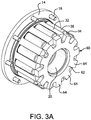
Fig. 3A is a perspective view of the clutch ofFig. 3 with one of the roll cages and hubs removed. -
Fig. 4 is an end view of the partially assembled clutch ofFig. 3 . -
Fig. 4A is an end view of the partially assembled clutch ofFig. 3A . -
Fig. 5 is a cross-sectional view of the partially assembled clutch ofFig. 3 taken along section 5-5 inFig. 4 . -
Fig. 5A is a cross-sectional view of the partially assembled clutch ofFig. 3A taken alongsection 5A-5A inFig. 4A . -
Fig. 6 is a perspective view of another bi-directional overrunning clutch that helps illustrate the present invention. -
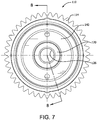
Fig. 7 is an end view of the clutch ofFig. 6 . -
Fig. 8 is a cross-sectional view of the clutch ofFig. 7 , taken along section 8-8. -
Figs. 9-11 are isometric sectional views of an embodiment of a bi-directional overrunning clutch according to the present invention. -
Fig. 12 is a cross-section view of the clutch ofFig. 9 in a differential housing. -
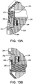
Figs. 13A and 13B are enlarged views of a portion of the clutch ofFig. 12 . - A
bi-directional overrunning clutch 10 is shown inFigs. 1-5A . Theclutch 10 includes ahousing 12 and aflange 14 affixed to thehousing 12. Theflange 14 is adapted to receive an input gear, sprocket, or other drive component that is engaged with an external drive mechanism for imparting rotational movement to theflange 14 and thus to thehousing 12. As depicted, theflange 14 includesbolt holes 16 for attaching the gear, it being understood that the gear may be attached to theflange 14 by any mechanical means known in the art, or may be formed as an integral part of theflange 14 orhousing 12. When the drive mechanism rotates the gear, theflange 14 rotates, which in turn rotates thehousing 12. - As shown in
Figs. 4 and4A , thehousing 12 includes a substantially cylindricalinner surface 80. Theinner surface 80 includes a plurality of aninner cam surfaces 82 including forward andreverse cam surfaces housing 12, eithersurface - As shown in
Figs. 2 and5 , a pair ofhubs 20 is located within thehousing 12. Thehubs 20 are substantially coaxially aligned with each other within thehousing 12, and are each adapted to rotate about their common axis within thehousing 12. In the depicted arrangement ofFig. 2 , thehubs 20 are not identical, but rather are mated to ensure their axial alignment. In particular, afirst hub 20a includes a substantiallycylindrical socket 90 while asecond hub 20b includes a substantially cylindricalaxial protrusion 92 adapted to be received into thesocket 90. - The
first hub 20a is adapted to engage an end of a first shaft of a primary drive axle (not shown) and thesecond hub 20b is adapted to engage an end of a second shaft of the primary drive axle (not shown). Eachhub 20 has a substantially cylindricalouter surface 24 having a diameter smaller than the diameter of theinner surface 80 of thehousing 12, so that an annular space is formed between theouter surface 24 of thehubs 20 and theinner surface 80 of thehousing 12. Eachhub 20 preferably has aninternal bore 26 into which a portion of a primary drive axle shaft is received. In the depicted arrangement, theinternal bores 26 include splines to allow the shafts to move axially inward and outward with respect to thehubs 20 while ensuring that each shaft will rotate along with itsrespective hub 20. In other arrangements, other mechanical connections between each shaft and itsrespective hub 20 may be used to ensure rotational coupling. It is further contemplated that thehubs 20 may be formed integrally with the primary drive shafts. - A pair of
roller assemblies 30 is located within thehousing 12, with a portion of eachroller assembly 30 being situated in the annular space between theouter surface 24 of one of thehubs 20 and theinner surface 80 of thehousing 12. As shown in detail inFigs. 2 ,3 , and4A eachroller assembly 30 includes aroll cage 32 formed in a substantially cylindrical shape. Eachroll cage 32 corresponds to one of thehubs 20 and has a set ofslots 34 spaced around the circumference of theroll cage 32. Eachslot 34 is adapted to receive acylindrical roller 36. Collectively, theslots 34 of oneroll cage 32 position a plurality ofrollers 36 in the annular space between thefirst hub 20a and theinner cam surface 82 of thehousing 12, and theslots 34 of theother roll cage 32 positions a plurality ofrollers 36 in the annular space between thesecond hub 20b and theinner cam surface 82 of thehousing 12. In one arrangement, each set ofrollers 36 has ten rollers, it being understood that any number of rollers greater than or equal to three may be used. As shown, eachroller 36 is substantially cylindrical, but rollers of other shapes may be used, including but not limited to substantially spherical rollers. - The
rollers 36 surrounding eachhub 20 are adapted to be wedgingly engaged between thehub 20 and theinner cam surface 82 of thehousing 12 when the associatedhub 20 and thehousing 12 are rotated with respect to the other. In particular, when thehousing 12 is rotationally driven by an external drive mechanism at a speed faster than thehubs 20 are rotating, therollers 36 are designed to wedgingly engage between the forward cam surfaces 82a in the housing and theouter surfaces 24 of thehubs 20, causing thehubs 20 to rotate with thehousing 12. Similarly, when bothhubs 20 are rotating faster than thehousing 12, such as during a descent or deceleration, thehubs 20 cause therollers 36 to wedge between the reverse cam surfaces 82b and theouter surfaces 24 of thehubs 20. The reverse cam surface engagement enables an engine braking or back driving effect, when available, whereby the reduced speed of the input gear slows or brakes the drive axles. - Providing two
separate roller assemblies 30, each having a set ofrollers 36 associated with one of thehubs 20, allows overrunning of onehub 20 while maintaining positive driving engagement of theother hub 20. For example, in a wheeled vehicle in which thehubs 20 drive wheels on opposite sides of the vehicle, when the vehicle travels around a curve, the wheel on the inside of the curve has a shorter distance to travel, and thus travels at a slower speed, than the wheel on the outside of the curve. Consequently, when thehousing 12 is being rotationally driven while the vehicle is in a curve, the onehub 20, forexample hub 20a, associated with the inside wheel will continue to be driven, with itsrespective rollers 36 engaged between theouter surface 24 of thehub 20a and the forward cam surfaces 82a of theinner surface 80 of thehousing 12, while theother hub 20, forexample hub 20b, associated with the outside wheel will be allowed to overrun, turning faster than thehousing 12, such that itsrespective rollers 36 disengage from their wedging between the inner cam surfaces 82 and theouter surface 24 of thehub 20b, thus allowing thehub 20b to freely rotate as it is driven by the outer wheel. When the vehicle returns to a straight path and the speed of thedisengaged hub 20b slows down to equal the speed of thehousing 12, therollers 36 surrounding thehub 20b re-engage (wedge) between the forward cam surfaces 82a andhub 20b so that thehub 20b is once again driven to rotate at the same speed as thehousing 12. - However, since the current clutch uses a split roll cage, if the two
roll cage assemblies 30 were completely decoupled, there is the potential that therollers 36 associated with the overrunninghub 20b could go into reverse engagement with the reverse cam surfaces 82b of theinner surface 80 of thehousing 12, thereby causing the vehicle to act as if it has a solid axle (i.e., one axle being driven by thehousing 12, while the other axle tries to drive the housing 12). To overcome potential reverse engagement of an overrunninghub 20, the clutch 10 includes aroll cage coupler 60 positioned between the tworoll assemblies 30, as shown inFigs. 2 ,3 ,3A ,4A ,5 , and5A . Thecoupler 60 includes ahub 62 with a plurality ofteeth 64 extending radially outward from thehub 62. The number ofteeth 64 preferably matches the number ofslots 34 and the number ofrollers 36 in eachroll cage 32. As shown most clearly inFigs. 5 and5A , theteeth 64 of thecoupler 60 preferably fit into theslots 34 in eachroll cage 32. As shown inFig. 4A , the width W1 of the portion of eachtooth 64 within aslot 34 is slightly less than the width W2 of theslot 34 of theroll cages 32 such that a gap exists. This gap is designed to permit aroll cage 32 to shift or index as discussed herein so that therollers 36 are positioned to engage with the cam surface, but the gap is not large enough to permit theother roll cage 32 to index in the opposite direction. Accordingly, by using anintermittent coupler 60, the present split cage design of the present invention prevents the issue of one set of rollers engaging the forward cam surface to drive one axle and the other set of rollers engaging the reverse cam surface to be driven by the other axle. - Rotationally coupling together two
separate roll cages 32 with anintermittent coupler 60 allows eachroll cage 32 to move axially with respect to its associatedhub 20, which enables a compact and simple friction disk mechanism to index eachroll cage 32 relative to its associatedhub 20, as discussed in detail below. The intermittent coupler also allows for a large torque difference from one axle to the other, and also allows for larger manufacturing tolerances in the clutch cam profile and hub diameters. The intermittent coupler also provides a method for retaining the roll assemblies in axial position to prevent one set from contacting the other. - An
end cap 40 is attached to each end of thehousing 12 so as to rotate with thehousing 12. To assist in indexing theroll cage assemblies 30 to theircorresponding hubs 20, eachend cap 40 is associated with afriction disk mechanism 50, shown in detail inFigs. 2 ,3 ,5 , and5A . Eachfriction disk mechanism 50 creates a frictional engagement between its associatedroll cage assembly 30 andhub 20 so thatroll cages 32 rotate with thehubs 20 when bothhubs 20 are rotating. In combination, thefriction disk mechanisms 50 and theroll cage coupler 60 make up an indexing assembly. - In particular, when a wheeled vehicle is stationary such that the
hubs 20 are stationary, and rotational movement is applied to thehousing 12 via an external drive mechanism, thehousing 12 begins to rotate with respect to thehubs 20. Thefriction disk mechanisms 50 prevent theroll cage assemblies 30 from rotating with respect to the hubs 20 (thus indexing theroll cage assemblies 30 relative to the housing 12). Indexing places therollers 36 in position so that they can wedgingly engage between the forward cam surfaces 82a and thehub 20. Once therollers 36 are wedgingly engaged, thehousing 12, theroll cages 32, and thehubs 20 all rotate together, and therollers 36 remain non-rotating about their own axes. - During overrunning of one
hub 20, for example,hub 20a, the friction of eachfriction disk mechanism 50 continues to hold its associatedroll cage assembly 30 in position relative to thehousing 12. The speed of the overrunninghub 20a, however, is faster than the speed of theroll cage 32, thus causing thehub 20a to drive therollers 36 in theroll cage assembly 30 associated with thehub 20a out of their wedging engagement so that thehub 20a can rotate faster than thehousing 12. At this point therollers 36 in theroll cage assembly 30 associated withhub 20a are free to rotate about their own axes. Theother hub 20,hub 20b, continues to be driven at the same rotational speed as thehousing 12, with its correspondingrollers 36 wedged into engagement. Theroll cage coupler 60 couples the tworoller assemblies 30 so that both remain engaged to the driven (non-overrunning)hub 20b, thereby preventing either or both of theroller assemblies 30 from indexing from forward engagement of therollers 36 into reverse engagement. The gap between the intermittent coupler and roll cages (difference between W2 and W1) is designed to allow limited movement for proper function within the assembly system. - Each
friction disk mechanism 50 may include a friction plate ordisk 52 that is attached to, formed on, or engaged with theroll cage 32 so as to rotate in combination with theroll cage 32. Thefriction plate 52 can be permanently or removably attached to theroll cage 32, or may simply be a surface on theroll cage 32. In one arrangement, thefriction plate 52 is a substantially planar annular ring with radially extending tabs or teeth that are sized to extend into theslots 34 on theroll cage 32 when thefriction plate 52 is placed within theroll cage 32 and adjacent to aninside end surface 51 of theroll cage 32. Thefriction plate 52 is configured to engage with a portion of thehub 20. More specifically, in one arrangement, thehub 20 includes acontact surface 54, which may be integral with, formed on, or attached to the hub, preferably on an axial end surface of the hub so as to be adjacent to a portion of thefriction plate 52. The portions of thefriction plate 52 andcontact surface 54 that contact one another preferably have a sufficient coefficient of friction to create frictional contact for transferring torque between the two as contemplated by the present invention. - A
spring 58 is compressed between a bearing 56 and anouter surface 55 on theroll cage 32. In the depicted arrangement, thespring 58 is a wave spring. Thespring 58 biases theroll cage 32, and thus thefriction plate 52, into thecontact surface 54 of thehub 20. As such, thespring 58 causes theroll cage 32 to move axially with respect to thehub 20, thereby urging thefriction plate 52 into frictional engagement with thehub 20. To inhibit or prevent torsional forces from being imposed on thespring 58 by theend cap 40, the bearing 56 may include at least one lowfriction coefficient surface 59. In one arrangement, the lowfriction coefficient surface 59 is on a side of the contact surface that engages with thespring 58, such that if thebearing 56 were to rotate along with theend cap 40, the bearing 56 would impose only minimal torsional loading on thespring 58. In another embodime arrangement nt, the lowfriction coefficient surface 59 is on a side of the contact surface that engages with theend cap 40. As such, the lowfriction coefficient surface 59 substantially prevents the bearing 56 from rotating with theend cap 40. In another arrangement, the lowfriction coefficient surface 59 may be on both sides of thebearing 56 and is in contact with both thespring 58 and a portion of theend cap 40. In one arrangement, thebearing 56 is a thrust washer or thrust bearing that permits rotational motion between thespring 58 and theend cap 40. In another arrangement, thebearing 56 is an annular ring of sufficient strength to provide rigid support for thespring 58. - Another arrangement of a
bi-directional overrunning clutch 110 is shown inFigs. 6-8 . The clutch 110 includes ahousing 112 and agear 114 affixed to thehousing 112. Thegear 114 is adapted to be engaged with an external drive mechanism that imparts rotational movement to thegear 114 and thus to thehousing 112. Although not specifically depicted, thehousing 112 includes substantially cylindricalinner surface 180 having a plurality of inner cam surfaces including forward and reverse cam surfaces, as described previously. - As shown in
Fig. 8 , a pair ofhubs 120 is located within thehousing 112. Thehubs 120 are substantially coaxially aligned with each other within thehousing 112, and are each adapted to rotate about their common axis within thehousing 112. Eachhub 120 has a substantially cylindricalouter surface 124 having a diameter smaller than the diameter of theinner surface 180 of thehousing 112, so that an annular space is formed between theouter surface 124 of thehubs 120 and the inner surface of thehousing 112. Eachhub 120 has aninternal bore 126 into which a portion of a primary drive axle shaft is received. In the depicted arrangement, theinternal bores 126 include splines to allow the shafts to move axially inward and outward with respect to thehubs 120 while ensuring that each shaft will rotate along with itsrespective hub 120. In other arrangement, other mechanical connections between each shaft and itsrespective hub 120 may be used to ensure rotational coupling. - A pair of
roller assemblies 130 is located within thehousing 112, with a portion of eachroller assembly 130 being situated in the annular space between theouter surface 124 of one of thehubs 120 and theinner surface 180 of thehousing 112. Eachroller assembly 130 includes aroll cage 132 formed in a substantially cylindrical shape. Eachroll cage 132 corresponds to one of thehubs 120 and has a set of slots 134 spaced around the circumference of theroll cage 132. Each slot 134 is adapted to receive acylindrical roller 136. Collectively, the slots 134 of oneroll cage 132 position a plurality ofrollers 136 in the annular space between thefirst hub 120a and the inner cam surface of thehousing 112, and the slots 134 of theother roll cage 132 position a plurality ofrollers 136 in the annular space between thesecond hub 120b and the inner cam surface of thehousing 112. In one arrangement, each set ofrollers 136 has ten rollers, it being understood that any number of rollers greater than or equal to three may be used. As shown, eachroller 136 is substantially cylindrical, but rollers of other shapes may be used, including but not limited to substantially spherical rollers. - The
rollers 136 surrounding eachhub 120 are adapted to be wedgingly engaged between thehub 120 and the inner cam surface of thehousing 112 when one of thehubs 120 and thehousing 112 is rotated with respect to the other. In particular, when thehousing 112 is rotationally driven by an external drive mechanism at a speed faster than thehubs 120 are rotating, therollers 136 wedgingly engage forward cam surfaces in the housing and theouter surfaces 124 of thehubs 120, causing thehubs 120 to rotate with thehousing 112. Similarly, when the drive shafts andhubs 120 are both rotating faster than thehousing 112, such as during a descent, thehubs 120 cause therollers 136 to engage with the reverse cam surfaces, resulting in a back driving or engine brake effect, when available. - To prevent potential reverse engagement of one
hub 120 while theother hub 120 is in forward engagement, the clutch 110 includes a roll cageintermittent coupler 160 positioned between the tworoll assemblies 130, as shown inFig. 8 . Thecoupler 160 includes a hub with a plurality of teeth extending radially outward from the hub. The number of teeth preferably matches the number of slots 134 and the number ofrollers 136 in eachroll cage 132, although there could be less teeth. As discussed above with respect to the prior emb arrangement odiment, the teeth of thecoupler 160 have a width that is less than the width of the slots 134 so as to define a gap that permits indexing of one cage relative to the other. - An
end cap 140 is attached to or disposed about each end of thehousing 112 and may rotate with thehousing 112. To assist in indexing theroll cage assemblies 130 to theircorresponding hubs 120, afriction disk mechanism 150 is located between eachroll cage assembly 130 and its associatedhub 120. Eachfriction disk mechanism 150 urges its correspondingroll cage assembly 130 to frictionally engage with thecorresponding hub 120 so that theroll cages 132 rotate with thehubs 120 when both hubs rotate. - Each
friction disk mechanism 150 is similar to thefriction disk mechanism 50 described above and includes afriction plate 152 that engages with acontact surface 154 on thehub 120. Abearing 156 is disposed between one end of aspring 158 and an inner surface of theend cap 140. The other end of thespring 158 contacts anouter surface 155 on theroll cage 132. As such, the tworoll cages 132 are biased toward one another, forcing thefriction plates 152 into contact with the contact surfaces 154. Thespring 158 is preferably a wave spring, although other springs and or elastomers can be used. Thebearing 158 may include one or more low friction surfaces as discussed above. - Referring now to
Figs. 9-14 , an embodiment of thebi-directional clutch 210 is shown. Many features of this clutch are similar to the arrangements disclosed above. As will be discussed below, this embodiment includes a different friction disk mechanism (or drag assembly) 250 which allows for ease of assembly and reduces tolerance buildups. As shown thehubs 220 are similar to the hubs discussed above except that there is abushing 222 located inrecesses 224 formed in the inward ends of eachhub 220. Thebushing 220 is intended to keep the hubs aligned on the same axis to one another to reduce/minimize hub flex from the axle loading. Aspring 226, such as a wave spring, or similar biasing member is located between at least one of the hubs and one side of thebushing 222. Thewave spring 226 biases both friction disk drag sub-assemblies to the inside surfaces of covers inFig 13 . Each hub preferably includes anouter recess 228 located on an outward end of thehub 220. Thefriction disk mechanism 250 includes aspring 258, such as a wave spring, or similar biasing member is located in therecess 228. Afriction disk 252, similar tofriction disk 52, is located against a face of thehub spacer 260, sandwiching thespring 258 between thefriction disk 252 and thehub 220. Ahub spacer 260 is located between an end cap or cover 240 and thefriction disk 252. As shown, thespacer 260 is preferably T-shaped with its large flat surface oriented so as to contact thefriction disk 252. Thehub spacer 260 is mechanically connected to thehub 220. The connection can be through any conventional means, but is preferably a spline connection. This connection keepshub 220 andhub spacer 260 rotatably engaged. Thehub spacer 260 extends out of an opening in the cover to help pilot the cover and ring gear. Preferably there is a friction material on the ace of the friction disk. The friction material is similar to the friction material used in conventional clutch packs and, therefore, no further description is necessary. - A retaining
ring 262 is located between thehub spacer 260 and thehub 220. Specifically, the retainingring 262 engages arecess 264 formed in thehub 220 or more particularly in a race portion of thehub 220. The retainingring 262 engages an outer facing surface of thehub spacer 260. As should be apparent from the drawings, the retainingring 262 is configured to urge thehub spacer 260 intofriction disk 252, which in turn compresses thespring 258 into thehub 220. - Each
friction disk 252 has radial extended tabs orteeth 253 that are sized to extend adjacent to anouter ring portion 233 ofroll cage 232. The tabs orteeth 253 engage theroll cage 232 so as to rotate in combination with theroll cage 232. This friction disk arrangement is not exclusive and the plate or disk can be attached to, formed on, or engaged with theroll cage 232 by other means to ensure rotation with theroll cage 232. The large inner surface of eachhub spacer 260 are in frictional contact withfriction disk 252. Thespring 258 biases thefriction disk 252 outward causing thefriction disk 252 to frictionally contact thehub spacer 260. The frictional engagement causes theroll cage 232 to drag or index the rollers into wedging engagement between thehub 220 and inner cam surfaces of the clutch housing. - Although the spring is shown in a recess in the hub, those skilled in the art would appreciate that the system will also work with the spring pushing off the hub spacer and the friction disk mated with the hub. Also the spring could be mounted so as to bias the friction disk to the hub. Also, the roll cage could be formed so as to form an interface between the hub spacer and the hub, and the friction material can be bonded to the outside or insider of the area of the roll cage that would be facing the friction disk.
- While the invention has been disclosed with reference to certain preferred embodiments, numerous modifications, alterations, and changes to the described embodiments are possible without departing from the sphere and scope of the invention, as defined in the appended claims. Accordingly, it is intended that the invention not be limited to the described embodiments, but that it have the full scope defined by the language of the following claims.
Claims (11)
- A bi-directional overrunning clutch (210) comprising:a housing (12, 212) adapted to be engaged with and rotated by a drive mechanism, the housing including an inner cam surface (82);a pair of hubs (220) substantially coaxially aligned with each other within the housing and adapted to engage first and second shafts of a primary drive axle;a roller assembly (30, 130) associated with each hub, each roller assembly including a roll cage (232) having a set of slots (34, 134) positioning a plurality of rollers (36, 136) in an annular space between the hub and the inner cam surface of the housing, the rollers being spaced about an associated hub and adapted to wedgingly engage between the hub and the inner cam surface when one of the hubs and the housing is rotated with respect to the other of the hubs and the housing;an end cap (240) associated with each hub and attached at each end of the housing;characterised in that the clutch further comprises:a friction disk mechanism (50, 150) associated with each hub and roller assembly for indexing the roller assembly relative to the hub, each friction disk mechanism including a friction plate (252) engaged with the roll cage so as to rotate in combination with the roll cage and positioned to contact a contact surface (54, 154) on the hub during operation, and a spring (258) compressed for biasing the friction plate into frictional contact with the contact surface of the hub; anda roll cage intermittent coupler (60) located between each roll cage, the coupler configured to engage the roll cages so as to permit indexing of one roll cage relative to the other;wherein the inner cam surface has a forward cam surface (82a) and a reverse cam surface (82b), such that when the housing is being driven with respect to at least one of the hubs, the rollers wedgingly engage between the forward cam surface and the at least one hub; andwherein when one of the hubs (220) is overrunning by rotating faster than the housing (212)and the other of the hubs, the roll cage coupler (60) is configured to prevent the one set of rollers (36, 136) engaging the forward cam surface and the other set of rollers engaging the reverse cam surface, thereby limiting the ability of the rollers to engage between the reverse cam surface of the housing and the one hub; andwherein the contact surface is on a hub spacer (260) connected to the hub (220) so as to rotate in combination therewith, and the spring (258) is mounted on the opposite side of the friction plate (252) from the contact surface and compressed between the hub (220) and the friction plate,and wherein the engagement of the friction plate and the roll cage (232) is provided by the spring biasing the friction plate into frictional engagement with a portion of the roll cage.
- The overrunning clutch (210) of claim 1, wherein the spring (258) is a wave spring.
- The overrunning clutch (210) of claims 1 or 2, wherein the friction plate (252) includes one or more radially extending teeth engaged with the roll cage (232).
- The overrunning clutch (210) of any of claims 1-3, further comprising a bearing surface (156) on the end cap (240), the spring (258) having an end that bears against the bearing surface.
- The overrunning clutch (210) of claim 4, wherein the bearing surface includes a low friction surface (259) in contact with the end of the spring (258).
- The overrunning clutch (210) of any of claims 1-5, wherein the roll cage coupler (60) includes one or more radially extending teeth (64) that each engage with one of the slots (34, 134) in each of the roll cages (232).
- The overrunning clutch (210) of any of claims 1-5, wherein the coupler (60) includes a coupler hub (62) with radially extending coupler teeth (64), each coupler tooth having a length and width (W1) designed to position the coupler tooth in a corresponding slot (34, 134) in both cages (232), the width of the coupler tooth being less than the width (W2) of the associated slots so as to define a gap that permits one roll cage to index with respect to the other roll cage and the coupler tooth.
- The overrunning clutch (210) of claim 7, wherein the gap is sized so that one roll cage (232) can index so as to position its rollers (36, 136) to engage with one of either the forward and rear cam surfaces (82a, 82b), while the coupler teeth (64) prevent the other roll cage from indexing in the other direction thereby preventing its rollers from engaging with the other of either the forward and rear cam surfaces.
- The overrunning clutch (210) of claim 1, wherein the contact surface (54, 154) is on the hub spacer (260), and wherein the spring (258) is mounted in a recess (228) in the hub on the opposite side of the friction plate (252).
- The overrunning clutch (210) of any of the preceding claims for use on a primary drive axle.
- A system to control torque transmission on a drive shaft of a wheeled machine including an overrunning clutch (210) according to any of claims 1-9.
Priority Applications (1)
| Application Number | Priority Date | Filing Date | Title |
|---|---|---|---|
| PL13878268T PL2971830T3 (en) | 2013-03-15 | 2013-05-03 | Bi-directional overrunning clutch having split roll cage |
Applications Claiming Priority (2)
| Application Number | Priority Date | Filing Date | Title |
|---|---|---|---|
| US13/832,473 US9022195B2 (en) | 2011-11-03 | 2013-03-15 | Bi-directional overrunning clutch having split roll cage and drag mechanism |
| PCT/US2013/039403 WO2014143090A1 (en) | 2013-03-15 | 2013-05-03 | Bi-directional overrunning clutch having split roll cage |
Publications (3)
| Publication Number | Publication Date |
|---|---|
| EP2971830A1 EP2971830A1 (en) | 2016-01-20 |
| EP2971830A4 EP2971830A4 (en) | 2016-05-11 |
| EP2971830B1 true EP2971830B1 (en) | 2018-07-11 |
Family
ID=51537406
Family Applications (1)
| Application Number | Title | Priority Date | Filing Date |
|---|---|---|---|
| EP13878268.5A Active EP2971830B1 (en) | 2013-03-15 | 2013-05-03 | Bi-directional overrunning clutch having split roll cage |
Country Status (8)
| Country | Link |
|---|---|
| EP (1) | EP2971830B1 (en) |
| CN (1) | CN105190070B (en) |
| AU (1) | AU2013381838B2 (en) |
| CA (1) | CA2904602C (en) |
| ES (1) | ES2690328T3 (en) |
| MX (1) | MX360676B (en) |
| PL (1) | PL2971830T3 (en) |
| WO (1) | WO2014143090A1 (en) |
Cited By (4)
| Publication number | Priority date | Publication date | Assignee | Title |
|---|---|---|---|---|
| US11047464B2 (en) | 2019-02-20 | 2021-06-29 | Team Industries, Inc. | Differential with bi-directional overrunning clutch |
| USD951064S1 (en) | 2019-09-20 | 2022-05-10 | Caterpillar Inc. | Spacer |
| US11592094B2 (en) | 2021-05-28 | 2023-02-28 | Team Industries, Inc. | Differential having an overrunning clutch with inertial compensation tuning |
| US11828354B2 (en) | 2021-05-28 | 2023-11-28 | Team Industries, Inc. | Overrunning clutch differential with a locking mechanism |
Families Citing this family (10)
| Publication number | Priority date | Publication date | Assignee | Title |
|---|---|---|---|---|
| CN105691578B (en) * | 2016-03-04 | 2018-04-03 | 北京工业大学 | The parallel double rolling key clutch axis system in naval vessel |
| US9856930B2 (en) * | 2016-03-16 | 2018-01-02 | The Hilliard Corporation | Bi-directional overrunning clutch with outer spring for a drive axle |
| US10337569B2 (en) | 2017-01-31 | 2019-07-02 | Schaeffler Technologies AG & Co. KG | Switchable one-way clutch |
| US10753408B2 (en) | 2017-02-14 | 2020-08-25 | Schaeffler Technologies AG & Co. KG | Switchable one-way clutch |
| FI127464B (en) * | 2017-02-17 | 2018-06-29 | Innotia Eesti Oue | Mechanical safety switch |
| US10451159B2 (en) | 2017-07-28 | 2019-10-22 | Schaeffler Technologies AG & Co. KG | Switchable one-way clutch |
| CN107327517B (en) * | 2017-08-29 | 2019-02-15 | 蒋祥初 | A two-way overrunning clutch |
| US10935085B2 (en) | 2018-05-14 | 2021-03-02 | Schaeffler Technologies AG & Co. KG | Switchable roller one-way clutch |
| US10781868B2 (en) | 2018-09-20 | 2020-09-22 | Schaeffler Technologies AG & Co. KG | Controllable one-way clutch |
| WO2020159937A1 (en) | 2019-01-28 | 2020-08-06 | Schaeffler Technologies AG & Co. KG | Four mode switchable one way clutch |
Family Cites Families (10)
| Publication number | Priority date | Publication date | Assignee | Title |
|---|---|---|---|---|
| US1175300A (en) * | 1912-04-12 | 1916-03-14 | Ross Gear & Tool Co | Differential mechanism. |
| US2191763A (en) * | 1938-12-27 | 1940-02-27 | Casse Hector J La | Differential |
| US3700082A (en) * | 1970-07-09 | 1972-10-24 | Hy Torq Corp | Differential drive mechanism |
| US3935753A (en) * | 1975-02-18 | 1976-02-03 | Warn Industries, Inc. | Positive drive differential |
| DE4219143A1 (en) * | 1992-06-11 | 1993-12-16 | Schaeffler Waelzlager Kg | Freewheel unit between rotary drive and rotary driven part - has clamping body freewheel and radial rolling bearing secured axially in the interspace between same and edges snap into groove |
| US6722484B2 (en) * | 2001-11-14 | 2004-04-20 | Hilliard Corporation | Bi-directional overrunning clutch for a primary drive axle |
| US7490708B2 (en) * | 2005-03-28 | 2009-02-17 | Kanzaki Kokyukoki Mfg. Co., Ltd. | Automatic traction enhancement for a transaxle |
| US8312792B1 (en) * | 2008-08-18 | 2012-11-20 | Kanzaki Kokyukoki Mfg. Co., Ltd. | Bi-directional overrunning clutched differential unit |
| US8646587B2 (en) * | 2010-12-10 | 2014-02-11 | Means Industries, Inc. | Strut for a controllable one-way clutch |
| US8857294B2 (en) * | 2010-12-15 | 2014-10-14 | The Hilliard Corporation | Engagement control assembly for a bi-directional overrunning clutch |
-
2013
- 2013-05-03 CN CN201380074737.1A patent/CN105190070B/en active Active
- 2013-05-03 EP EP13878268.5A patent/EP2971830B1/en active Active
- 2013-05-03 PL PL13878268T patent/PL2971830T3/en unknown
- 2013-05-03 AU AU2013381838A patent/AU2013381838B2/en active Active
- 2013-05-03 CA CA2904602A patent/CA2904602C/en active Active
- 2013-05-03 MX MX2015012750A patent/MX360676B/en active IP Right Grant
- 2013-05-03 ES ES13878268.5T patent/ES2690328T3/en active Active
- 2013-05-03 WO PCT/US2013/039403 patent/WO2014143090A1/en not_active Ceased
Non-Patent Citations (1)
| Title |
|---|
| None * |
Cited By (4)
| Publication number | Priority date | Publication date | Assignee | Title |
|---|---|---|---|---|
| US11047464B2 (en) | 2019-02-20 | 2021-06-29 | Team Industries, Inc. | Differential with bi-directional overrunning clutch |
| USD951064S1 (en) | 2019-09-20 | 2022-05-10 | Caterpillar Inc. | Spacer |
| US11592094B2 (en) | 2021-05-28 | 2023-02-28 | Team Industries, Inc. | Differential having an overrunning clutch with inertial compensation tuning |
| US11828354B2 (en) | 2021-05-28 | 2023-11-28 | Team Industries, Inc. | Overrunning clutch differential with a locking mechanism |
Also Published As
| Publication number | Publication date |
|---|---|
| MX2015012750A (en) | 2015-12-01 |
| CN105190070B (en) | 2018-05-01 |
| EP2971830A1 (en) | 2016-01-20 |
| AU2013381838A1 (en) | 2015-09-17 |
| CA2904602C (en) | 2018-02-06 |
| MX360676B (en) | 2018-11-13 |
| ES2690328T3 (en) | 2018-11-20 |
| EP2971830A4 (en) | 2016-05-11 |
| PL2971830T3 (en) | 2019-01-31 |
| WO2014143090A1 (en) | 2014-09-18 |
| AU2013381838B2 (en) | 2016-01-28 |
| CN105190070A (en) | 2015-12-23 |
| CA2904602A1 (en) | 2014-09-18 |
Similar Documents
| Publication | Publication Date | Title |
|---|---|---|
| US9022195B2 (en) | Bi-directional overrunning clutch having split roll cage and drag mechanism | |
| US8919513B2 (en) | Bi-directional overrunning clutch having split roll cage | |
| AU2013381838B2 (en) | Bi-directional overrunning clutch having split roll cage | |
| US8857589B2 (en) | Friction disk mechanism for bi-directional overrunning clutch | |
| US8857294B2 (en) | Engagement control assembly for a bi-directional overrunning clutch | |
| US6398686B1 (en) | Electronically controlled limited slip differential assembly | |
| EP2425154B1 (en) | Locking differential | |
| JP6267708B2 (en) | Rocking differential with preload spring combination for contact maintenance | |
| JP2004183892A (en) | Roller clutch mechanism | |
| WO2014159651A1 (en) | Bi-directional overrunning clutch with improved indexing mechanism | |
| US7588112B2 (en) | Bi-directional clutch and vehicle with it | |
| US10337570B2 (en) | Transaxle including bi-directional overrunning clutch | |
| US9151376B2 (en) | Locking differential having dampening communication spring | |
| CN104411528B (en) | Locking differential with reloading spring wear-resistant pad | |
| JP2019027533A (en) | Torque limiter | |
| US4569250A (en) | Positive drive with torque responsive dampener | |
| JP4318411B2 (en) | Two-way overrunning clutch mechanism | |
| JP2000320645A (en) | Differential device |
Legal Events
| Date | Code | Title | Description |
|---|---|---|---|
| PUAI | Public reference made under article 153(3) epc to a published international application that has entered the european phase |
Free format text: ORIGINAL CODE: 0009012 |
|
| 17P | Request for examination filed |
Effective date: 20150821 |
|
| AK | Designated contracting states |
Kind code of ref document: A1 Designated state(s): AL AT BE BG CH CY CZ DE DK EE ES FI FR GB GR HR HU IE IS IT LI LT LU LV MC MK MT NL NO PL PT RO RS SE SI SK SM TR |
|
| AX | Request for extension of the european patent |
Extension state: BA ME |
|
| REG | Reference to a national code |
Ref country code: DE Ref legal event code: R079 Ref document number: 602013040288 Country of ref document: DE Free format text: PREVIOUS MAIN CLASS: F16D0021080000 Ipc: F16D0041067000 |
|
| A4 | Supplementary search report drawn up and despatched |
Effective date: 20160413 |
|
| RIC1 | Information provided on ipc code assigned before grant |
Ipc: F16D 41/067 20060101AFI20160407BHEP Ipc: F16D 47/04 20060101ALI20160407BHEP |
|
| DAX | Request for extension of the european patent (deleted) | ||
| STAA | Information on the status of an ep patent application or granted ep patent |
Free format text: STATUS: EXAMINATION IS IN PROGRESS |
|
| 17Q | First examination report despatched |
Effective date: 20161128 |
|
| GRAP | Despatch of communication of intention to grant a patent |
Free format text: ORIGINAL CODE: EPIDOSNIGR1 |
|
| STAA | Information on the status of an ep patent application or granted ep patent |
Free format text: STATUS: GRANT OF PATENT IS INTENDED |
|
| INTG | Intention to grant announced |
Effective date: 20171214 |
|
| GRAS | Grant fee paid |
Free format text: ORIGINAL CODE: EPIDOSNIGR3 |
|
| GRAJ | Information related to disapproval of communication of intention to grant by the applicant or resumption of examination proceedings by the epo deleted |
Free format text: ORIGINAL CODE: EPIDOSDIGR1 |
|
| GRAL | Information related to payment of fee for publishing/printing deleted |
Free format text: ORIGINAL CODE: EPIDOSDIGR3 |
|
| STAA | Information on the status of an ep patent application or granted ep patent |
Free format text: STATUS: EXAMINATION IS IN PROGRESS |
|
| GRAR | Information related to intention to grant a patent recorded |
Free format text: ORIGINAL CODE: EPIDOSNIGR71 |
|
| STAA | Information on the status of an ep patent application or granted ep patent |
Free format text: STATUS: GRANT OF PATENT IS INTENDED |
|
| INTC | Intention to grant announced (deleted) | ||
| GRAA | (expected) grant |
Free format text: ORIGINAL CODE: 0009210 |
|
| STAA | Information on the status of an ep patent application or granted ep patent |
Free format text: STATUS: THE PATENT HAS BEEN GRANTED |
|
| INTG | Intention to grant announced |
Effective date: 20180514 |
|
| AK | Designated contracting states |
Kind code of ref document: B1 Designated state(s): AL AT BE BG CH CY CZ DE DK EE ES FI FR GB GR HR HU IE IS IT LI LT LU LV MC MK MT NL NO PL PT RO RS SE SI SK SM TR |
|
| REG | Reference to a national code |
Ref country code: GB Ref legal event code: FG4D |
|
| REG | Reference to a national code |
Ref country code: CH Ref legal event code: EP |
|
| REG | Reference to a national code |
Ref country code: AT Ref legal event code: REF Ref document number: 1017191 Country of ref document: AT Kind code of ref document: T Effective date: 20180715 |
|
| REG | Reference to a national code |
Ref country code: IE Ref legal event code: FG4D |
|
| REG | Reference to a national code |
Ref country code: DE Ref legal event code: R096 Ref document number: 602013040288 Country of ref document: DE |
|
| REG | Reference to a national code |
Ref country code: NL Ref legal event code: MP Effective date: 20180711 |
|
| REG | Reference to a national code |
Ref country code: ES Ref legal event code: FG2A Ref document number: 2690328 Country of ref document: ES Kind code of ref document: T3 Effective date: 20181120 |
|
| REG | Reference to a national code |
Ref country code: LT Ref legal event code: MG4D |
|
| REG | Reference to a national code |
Ref country code: AT Ref legal event code: MK05 Ref document number: 1017191 Country of ref document: AT Kind code of ref document: T Effective date: 20180711 |
|
| PG25 | Lapsed in a contracting state [announced via postgrant information from national office to epo] |
Ref country code: NL Free format text: LAPSE BECAUSE OF FAILURE TO SUBMIT A TRANSLATION OF THE DESCRIPTION OR TO PAY THE FEE WITHIN THE PRESCRIBED TIME-LIMIT Effective date: 20180711 |
|
| PG25 | Lapsed in a contracting state [announced via postgrant information from national office to epo] |
Ref country code: FI Free format text: LAPSE BECAUSE OF FAILURE TO SUBMIT A TRANSLATION OF THE DESCRIPTION OR TO PAY THE FEE WITHIN THE PRESCRIBED TIME-LIMIT Effective date: 20180711 Ref country code: RS Free format text: LAPSE BECAUSE OF FAILURE TO SUBMIT A TRANSLATION OF THE DESCRIPTION OR TO PAY THE FEE WITHIN THE PRESCRIBED TIME-LIMIT Effective date: 20180711 Ref country code: IS Free format text: LAPSE BECAUSE OF FAILURE TO SUBMIT A TRANSLATION OF THE DESCRIPTION OR TO PAY THE FEE WITHIN THE PRESCRIBED TIME-LIMIT Effective date: 20181111 Ref country code: AT Free format text: LAPSE BECAUSE OF FAILURE TO SUBMIT A TRANSLATION OF THE DESCRIPTION OR TO PAY THE FEE WITHIN THE PRESCRIBED TIME-LIMIT Effective date: 20180711 Ref country code: NO Free format text: LAPSE BECAUSE OF FAILURE TO SUBMIT A TRANSLATION OF THE DESCRIPTION OR TO PAY THE FEE WITHIN THE PRESCRIBED TIME-LIMIT Effective date: 20181011 Ref country code: GR Free format text: LAPSE BECAUSE OF FAILURE TO SUBMIT A TRANSLATION OF THE DESCRIPTION OR TO PAY THE FEE WITHIN THE PRESCRIBED TIME-LIMIT Effective date: 20181012 Ref country code: BG Free format text: LAPSE BECAUSE OF FAILURE TO SUBMIT A TRANSLATION OF THE DESCRIPTION OR TO PAY THE FEE WITHIN THE PRESCRIBED TIME-LIMIT Effective date: 20181011 Ref country code: SE Free format text: LAPSE BECAUSE OF FAILURE TO SUBMIT A TRANSLATION OF THE DESCRIPTION OR TO PAY THE FEE WITHIN THE PRESCRIBED TIME-LIMIT Effective date: 20180711 Ref country code: LT Free format text: LAPSE BECAUSE OF FAILURE TO SUBMIT A TRANSLATION OF THE DESCRIPTION OR TO PAY THE FEE WITHIN THE PRESCRIBED TIME-LIMIT Effective date: 20180711 |
|
| PG25 | Lapsed in a contracting state [announced via postgrant information from national office to epo] |
Ref country code: AL Free format text: LAPSE BECAUSE OF FAILURE TO SUBMIT A TRANSLATION OF THE DESCRIPTION OR TO PAY THE FEE WITHIN THE PRESCRIBED TIME-LIMIT Effective date: 20180711 Ref country code: LV Free format text: LAPSE BECAUSE OF FAILURE TO SUBMIT A TRANSLATION OF THE DESCRIPTION OR TO PAY THE FEE WITHIN THE PRESCRIBED TIME-LIMIT Effective date: 20180711 Ref country code: HR Free format text: LAPSE BECAUSE OF FAILURE TO SUBMIT A TRANSLATION OF THE DESCRIPTION OR TO PAY THE FEE WITHIN THE PRESCRIBED TIME-LIMIT Effective date: 20180711 |
|
| REG | Reference to a national code |
Ref country code: DE Ref legal event code: R097 Ref document number: 602013040288 Country of ref document: DE |
|
| PG25 | Lapsed in a contracting state [announced via postgrant information from national office to epo] |
Ref country code: RO Free format text: LAPSE BECAUSE OF FAILURE TO SUBMIT A TRANSLATION OF THE DESCRIPTION OR TO PAY THE FEE WITHIN THE PRESCRIBED TIME-LIMIT Effective date: 20180711 Ref country code: CZ Free format text: LAPSE BECAUSE OF FAILURE TO SUBMIT A TRANSLATION OF THE DESCRIPTION OR TO PAY THE FEE WITHIN THE PRESCRIBED TIME-LIMIT Effective date: 20180711 Ref country code: EE Free format text: LAPSE BECAUSE OF FAILURE TO SUBMIT A TRANSLATION OF THE DESCRIPTION OR TO PAY THE FEE WITHIN THE PRESCRIBED TIME-LIMIT Effective date: 20180711 |
|
| PLBE | No opposition filed within time limit |
Free format text: ORIGINAL CODE: 0009261 |
|
| STAA | Information on the status of an ep patent application or granted ep patent |
Free format text: STATUS: NO OPPOSITION FILED WITHIN TIME LIMIT |
|
| PG25 | Lapsed in a contracting state [announced via postgrant information from national office to epo] |
Ref country code: DK Free format text: LAPSE BECAUSE OF FAILURE TO SUBMIT A TRANSLATION OF THE DESCRIPTION OR TO PAY THE FEE WITHIN THE PRESCRIBED TIME-LIMIT Effective date: 20180711 Ref country code: SM Free format text: LAPSE BECAUSE OF FAILURE TO SUBMIT A TRANSLATION OF THE DESCRIPTION OR TO PAY THE FEE WITHIN THE PRESCRIBED TIME-LIMIT Effective date: 20180711 Ref country code: SK Free format text: LAPSE BECAUSE OF FAILURE TO SUBMIT A TRANSLATION OF THE DESCRIPTION OR TO PAY THE FEE WITHIN THE PRESCRIBED TIME-LIMIT Effective date: 20180711 |
|
| 26N | No opposition filed |
Effective date: 20190412 |
|
| PG25 | Lapsed in a contracting state [announced via postgrant information from national office to epo] |
Ref country code: SI Free format text: LAPSE BECAUSE OF FAILURE TO SUBMIT A TRANSLATION OF THE DESCRIPTION OR TO PAY THE FEE WITHIN THE PRESCRIBED TIME-LIMIT Effective date: 20180711 |
|
| REG | Reference to a national code |
Ref country code: CH Ref legal event code: PL |
|
| PG25 | Lapsed in a contracting state [announced via postgrant information from national office to epo] |
Ref country code: MC Free format text: LAPSE BECAUSE OF FAILURE TO SUBMIT A TRANSLATION OF THE DESCRIPTION OR TO PAY THE FEE WITHIN THE PRESCRIBED TIME-LIMIT Effective date: 20180711 Ref country code: CH Free format text: LAPSE BECAUSE OF NON-PAYMENT OF DUE FEES Effective date: 20190531 Ref country code: LI Free format text: LAPSE BECAUSE OF NON-PAYMENT OF DUE FEES Effective date: 20190531 |
|
| REG | Reference to a national code |
Ref country code: BE Ref legal event code: MM Effective date: 20190531 |
|
| PG25 | Lapsed in a contracting state [announced via postgrant information from national office to epo] |
Ref country code: LU Free format text: LAPSE BECAUSE OF NON-PAYMENT OF DUE FEES Effective date: 20190503 |
|
| PG25 | Lapsed in a contracting state [announced via postgrant information from national office to epo] |
Ref country code: TR Free format text: LAPSE BECAUSE OF FAILURE TO SUBMIT A TRANSLATION OF THE DESCRIPTION OR TO PAY THE FEE WITHIN THE PRESCRIBED TIME-LIMIT Effective date: 20180711 |
|
| PG25 | Lapsed in a contracting state [announced via postgrant information from national office to epo] |
Ref country code: IE Free format text: LAPSE BECAUSE OF NON-PAYMENT OF DUE FEES Effective date: 20190503 |
|
| PG25 | Lapsed in a contracting state [announced via postgrant information from national office to epo] |
Ref country code: BE Free format text: LAPSE BECAUSE OF NON-PAYMENT OF DUE FEES Effective date: 20190531 |
|
| PG25 | Lapsed in a contracting state [announced via postgrant information from national office to epo] |
Ref country code: PT Free format text: LAPSE BECAUSE OF FAILURE TO SUBMIT A TRANSLATION OF THE DESCRIPTION OR TO PAY THE FEE WITHIN THE PRESCRIBED TIME-LIMIT Effective date: 20181111 |
|
| PG25 | Lapsed in a contracting state [announced via postgrant information from national office to epo] |
Ref country code: CY Free format text: LAPSE BECAUSE OF FAILURE TO SUBMIT A TRANSLATION OF THE DESCRIPTION OR TO PAY THE FEE WITHIN THE PRESCRIBED TIME-LIMIT Effective date: 20180711 |
|
| PG25 | Lapsed in a contracting state [announced via postgrant information from national office to epo] |
Ref country code: HU Free format text: LAPSE BECAUSE OF FAILURE TO SUBMIT A TRANSLATION OF THE DESCRIPTION OR TO PAY THE FEE WITHIN THE PRESCRIBED TIME-LIMIT; INVALID AB INITIO Effective date: 20130503 Ref country code: MT Free format text: LAPSE BECAUSE OF FAILURE TO SUBMIT A TRANSLATION OF THE DESCRIPTION OR TO PAY THE FEE WITHIN THE PRESCRIBED TIME-LIMIT Effective date: 20180711 |
|
| PG25 | Lapsed in a contracting state [announced via postgrant information from national office to epo] |
Ref country code: MK Free format text: LAPSE BECAUSE OF FAILURE TO SUBMIT A TRANSLATION OF THE DESCRIPTION OR TO PAY THE FEE WITHIN THE PRESCRIBED TIME-LIMIT Effective date: 20180711 |
|
| PGFP | Annual fee paid to national office [announced via postgrant information from national office to epo] |
Ref country code: DE Payment date: 20250311 Year of fee payment: 13 |
|
| PGFP | Annual fee paid to national office [announced via postgrant information from national office to epo] |
Ref country code: ES Payment date: 20250605 Year of fee payment: 13 |
|
| PGFP | Annual fee paid to national office [announced via postgrant information from national office to epo] |
Ref country code: IT Payment date: 20250422 Year of fee payment: 13 |
|
| PGFP | Annual fee paid to national office [announced via postgrant information from national office to epo] |
Ref country code: GB Payment date: 20260312 Year of fee payment: 14 |
|
| PGFP | Annual fee paid to national office [announced via postgrant information from national office to epo] |
Ref country code: FR Payment date: 20260309 Year of fee payment: 14 |
|
| PGFP | Annual fee paid to national office [announced via postgrant information from national office to epo] |
Ref country code: PL Payment date: 20260317 Year of fee payment: 14 |