EP2971796B1 - Servo actuator - Google Patents
Servo actuator Download PDFInfo
- Publication number
- EP2971796B1 EP2971796B1 EP14721051.2A EP14721051A EP2971796B1 EP 2971796 B1 EP2971796 B1 EP 2971796B1 EP 14721051 A EP14721051 A EP 14721051A EP 2971796 B1 EP2971796 B1 EP 2971796B1
- Authority
- EP
- European Patent Office
- Prior art keywords
- actuator
- servo
- metering
- fluid
- ports
- Prior art date
- Legal status (The legal status is an assumption and is not a legal conclusion. Google has not performed a legal analysis and makes no representation as to the accuracy of the status listed.)
- Not-in-force
Links
- 239000012530 fluid Substances 0.000 claims description 52
- 238000000034 method Methods 0.000 claims description 9
- 230000009977 dual effect Effects 0.000 claims description 2
- 230000000712 assembly Effects 0.000 description 6
- 238000000429 assembly Methods 0.000 description 6
- 230000006835 compression Effects 0.000 description 3
- 238000007906 compression Methods 0.000 description 3
- 230000008878 coupling Effects 0.000 description 2
- 238000010168 coupling process Methods 0.000 description 2
- 238000005859 coupling reaction Methods 0.000 description 2
- 230000006870 function Effects 0.000 description 2
- 238000003491 array Methods 0.000 description 1
- 238000004891 communication Methods 0.000 description 1
- 238000013016 damping Methods 0.000 description 1
- 238000006073 displacement reaction Methods 0.000 description 1
- 230000002401 inhibitory effect Effects 0.000 description 1
- 230000007935 neutral effect Effects 0.000 description 1
- 230000003071 parasitic effect Effects 0.000 description 1
- 238000005086 pumping Methods 0.000 description 1
- 239000000758 substrate Substances 0.000 description 1
Images



Classifications
-
- F—MECHANICAL ENGINEERING; LIGHTING; HEATING; WEAPONS; BLASTING
- F15—FLUID-PRESSURE ACTUATORS; HYDRAULICS OR PNEUMATICS IN GENERAL
- F15B—SYSTEMS ACTING BY MEANS OF FLUIDS IN GENERAL; FLUID-PRESSURE ACTUATORS, e.g. SERVOMOTORS; DETAILS OF FLUID-PRESSURE SYSTEMS, NOT OTHERWISE PROVIDED FOR
- F15B11/00—Servomotor systems without provision for follow-up action; Circuits therefor
- F15B11/006—Hydraulic "Wheatstone bridge" circuits, i.e. with four nodes, P-A-T-B, and on-off or proportional valves in each link
-
- F—MECHANICAL ENGINEERING; LIGHTING; HEATING; WEAPONS; BLASTING
- F15—FLUID-PRESSURE ACTUATORS; HYDRAULICS OR PNEUMATICS IN GENERAL
- F15B—SYSTEMS ACTING BY MEANS OF FLUIDS IN GENERAL; FLUID-PRESSURE ACTUATORS, e.g. SERVOMOTORS; DETAILS OF FLUID-PRESSURE SYSTEMS, NOT OTHERWISE PROVIDED FOR
- F15B2211/00—Circuits for servomotor systems
- F15B2211/30—Directional control
- F15B2211/305—Directional control characterised by the type of valves
- F15B2211/3056—Assemblies of multiple valves
- F15B2211/30565—Assemblies of multiple valves having multiple valves for a single output member, e.g. for creating higher valve function by use of multiple valves like two 2/2-valves replacing a 5/3-valve
- F15B2211/30575—Assemblies of multiple valves having multiple valves for a single output member, e.g. for creating higher valve function by use of multiple valves like two 2/2-valves replacing a 5/3-valve in a Wheatstone Bridge arrangement (also half bridges)
-
- F—MECHANICAL ENGINEERING; LIGHTING; HEATING; WEAPONS; BLASTING
- F15—FLUID-PRESSURE ACTUATORS; HYDRAULICS OR PNEUMATICS IN GENERAL
- F15B—SYSTEMS ACTING BY MEANS OF FLUIDS IN GENERAL; FLUID-PRESSURE ACTUATORS, e.g. SERVOMOTORS; DETAILS OF FLUID-PRESSURE SYSTEMS, NOT OTHERWISE PROVIDED FOR
- F15B2211/00—Circuits for servomotor systems
- F15B2211/70—Output members, e.g. hydraulic motors or cylinders or control therefor
- F15B2211/705—Output members, e.g. hydraulic motors or cylinders or control therefor characterised by the type of output members or actuators
- F15B2211/7051—Linear output members
- F15B2211/7053—Double-acting output members
- F15B2211/7054—Having equal piston areas
-
- F—MECHANICAL ENGINEERING; LIGHTING; HEATING; WEAPONS; BLASTING
- F15—FLUID-PRESSURE ACTUATORS; HYDRAULICS OR PNEUMATICS IN GENERAL
- F15B—SYSTEMS ACTING BY MEANS OF FLUIDS IN GENERAL; FLUID-PRESSURE ACTUATORS, e.g. SERVOMOTORS; DETAILS OF FLUID-PRESSURE SYSTEMS, NOT OTHERWISE PROVIDED FOR
- F15B2211/00—Circuits for servomotor systems
- F15B2211/70—Output members, e.g. hydraulic motors or cylinders or control therefor
- F15B2211/76—Control of force or torque of the output member
-
- F—MECHANICAL ENGINEERING; LIGHTING; HEATING; WEAPONS; BLASTING
- F15—FLUID-PRESSURE ACTUATORS; HYDRAULICS OR PNEUMATICS IN GENERAL
- F15B—SYSTEMS ACTING BY MEANS OF FLUIDS IN GENERAL; FLUID-PRESSURE ACTUATORS, e.g. SERVOMOTORS; DETAILS OF FLUID-PRESSURE SYSTEMS, NOT OTHERWISE PROVIDED FOR
- F15B2211/00—Circuits for servomotor systems
- F15B2211/70—Output members, e.g. hydraulic motors or cylinders or control therefor
- F15B2211/76—Control of force or torque of the output member
- F15B2211/761—Control of a negative load, i.e. of a load generating hydraulic energy
Definitions
- a servo valve meters fluid from a pump to one of two ports of the dual-acting actuator, while also fluidly coupling the other port on an opposite side of a piston in the actuator to a return.
- precise positioning of the piston in the actuator cylinder can be obtained.
- the actuator thus exhibits characteristics of applying a displacement vector, that being moving a point or object a known distance from an initial to a final position.
- the hydraulic system may have an actuator with a first chamber and a second chamber.
- the hydraulic system may also have a first valve, a second valve, a third valve, and an operator input device displaceable from a neutral position to generate a signal indicative of a desired movement of the actuator.
- the hydraulic system may further have a controller configured to open the first and third valves by amounts related to the signal to pass fluid, and open the second valve by an amount related to the signal to pass fluid when the signal indicates a desire for increased actuator velocity.
- the third valve may continue to open during opening of the second valve.
- D3 discloses a hydraulic system for a machine as well.
- the hydraulic control system of D3 has a fluid actuator with first and second chambers, first and second metering valves having valve elements movable to fill and drain the first and second chambers respectively, and at least one fluid sensor configured to generate a load signal indicative of a load on the fluid actuator.
- the hydraulic control system also has an operator interface device movable to generate a desired velocity signal of the fluid actuator.
- the hydraulic control system further has a controller in communication with the first and second metering valves, the at least one fluid sensor, and the operator interface device.
- the controller is configured to move the valve element of the first metering valve to a position based on the desired velocity signal, to determine a desired pressure for the second chamber based on the load signal and a pressure associated with the first chamber, and to move the valve element of the second metering valve to a position based on the determined desired pressure.
- a servo actuator system according to claim 1, a method of controlling an actuator system according to claim 11 and a controller according to claim 15.
- the controller in the second state can control the first metering orifice to inhibit fluid flow therethrough while controlling the second metering orifice to allow fluid flow therethrough at a rate greater than that of a rate through the first metering orifice.
- the servo assembly can comprise four metering orifices and four ports, wherein a unique pair of metering orifices is fluidly connected to each port and each metering orifice controls fluid flow between a unique pair of ports.
- the single servo assembly having the four ports, or multiple, preferably two, conventional servo valve assemblies 70 and 72 can be used to realize the function of the four port servo valve assembly
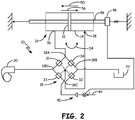
- FIGS. 1 and 2 illustrate a first embodiment of a servo actuator vector generating system 10 in two states of operation.
- the servo actuator vector generating system 10 generates a true vector (magnitude and direction) where the actual position of a movable member in an actuator body is indeterminate.
- the system 10 includes a dual-acting actuator 16 having a piston 12 (movable member) slidable in a cylinder 14 (actuator body).
- a rotatory actuator 17 as illustrated in FIG. 7 having a vane 15 (movable member) rotable in a housing 19.
- FIG. 7 having a vane 15 (movable member) rotable in a housing 19.
- the servo actuator vector generating system 10 generally comprises dual acting actuator 16, a servo valve assembly 18, and a pump 20 having a return indicated at 22.
- a conventional fluidic system hereinafter specifically referred to as a hydraulic system, but it should be understood aspects of the invention can be used with a pneumatic system as well
- the servo valve assembly 18 comprises metering orifices that selectively constrict fluid flow therethrough so as to increase pressure on one side of the piston 12 or the other.
- the servo valve assembly 18 includes four metering orifices 31, 32, 33 and 34 and four ports 18A, 18B, 18C and 18D, wherein a unique pair of metering orifices is fluidly connected to each port 18A, 18B, 18C and 18D and each metering orifice 31, 32, 33 and 34 controls fluid flow between a unique pair of ports.
- FIG.1 illustrates a zero force state of the actuator system 10.
- all metering orifices 31, 32, 33 and 34 of the servo valve assembly 18 are preferably completely open, or otherwise open such that fluid flow through the servo valve assembly 18 yields substantially equal pressure on each side of the piston 12.
- fluid flow through orifices 31 and 33 are substantially the same and if the piston 12 is stationary in the cylinder of the actuator 16, fluid flow through orifices 32 and 34 to the return 22 are also the same.
- actuator ports 36,38 are fluidly coupled to each other.
- the actuator piston 12 is free to move in either direction by any external disturbance applied to the piston 12 (indicated by double arrow 54) although there may be a slight amount of parasitic viscous damping due to fluid porting.
- the hydraulic pump 20 is simply pumping hydraulic fluid with no or minimal pressure through the servo valve assembly 18 to the return 22.
- a controller is schematically indicated at 40 and receives a command signal 44.
- a transducer suitable for providing an indication of force applied by the actuator 16 is operably coupled to the actuator.
- the transducer comprises a load cell 46 operably connected to the actuator 16 such as through a piston rod 48 to provide a signal indicative of a force generated by the actuator 16 to the controller 40.
- the load cell 46 can be operably connected to the actuator 16 in another manner such as being operably coupled to the cylinder 14.
- pressure transducer(s) can be operably coupled to the actuator 16 so as to measure fluid pressure(s) on one or both sides of the piston 12. The measured pressure(s) can then be converted or used directly by the controller 40 as an indication of force generated by the actuator 16.
- the controller 40 controls the switching assembly 18 (i.e. a proportional valve assembly) selectively operating the switching assembly 18 (typically by controlling movement of a metering spools) so as to cause the metering orifices 31-34, based upon the command 44, to selectively constrict, thereby inhibiting or reducing fluid flow therethrough and subsequently increasing the pressure on one side of the metering orifice 31-34.
- the switching assembly 18 i.e. a proportional valve assembly
- the controller 40 is operably coupled to the servo assembly 18 to operate the servo actuator system in a first state and a second state, wherein in the first state the controller 40 controls each of the plurality of metering orifices 31-34 such that fluid from the pump 20 flows to the return 22 and fluid transfers freely in and out of the ports 36, 38 with an external force applied to the movable member 12, and wherein in the second state the controller 40 controls each of the plurality of metering orifices 31-34 such that fluid pressure from the pump 20 causes movement of the movable member 12 in the actuator body 14 while allowing cross flow of fluid between the ports 36, 38.
- a tension force state is obtained in the actuator system 10 whereby the actuator piston 12 is forced in a direction indicated by arrow 50. From the zero force state of FIG. 1 , this is accomplished by controlling metering orifices 31 and 32 to constrict fluid flow therethrough while maintaining 33 and 34 in an open state (or a more open state than that of the metering orifices 31 and 32). This results in a pressure rise at the port 38 caused by constriction of the metering orifices 31 and 32, while allowing unrestricted flow from port 36 to the return 22. However, since the ports 36 and 38 still have some cross flow capability indicated by double arrow 54, the actual position of the piston 12 in the actuator cylinder 14 is indeterminate; thus; realizing a true force vector being applied by the actuator 16.
- a compression force state of the actuator system 10 is obtained by controlling metering orifices 33 and 34 to cause constriction, while maintaining metering orifices 31 and 32 in an open state (or a more open state than metering orifices 33 and 34).
- This realizes a pressure rise at port 36 and unrestricted flow from port 38 to reserve 22, while again maintaining actuator ports 36 and 38 with some crossflow capability.
- a pressure rise at port 36 causes force independent of position applied to the piston 12 in a direction indicated by arrow 56.
- FIG. 3 illustrates use of two conventional servo valve assemblies 70 and 72 to realize the function of the four port servo valve assembly 18 illustrated in FIGS. 1 and 2 .
- the same reference numerals have been used to identify similar components illustrated in FIGS. 1 and 2 .
- the servo valve assembly 70 comprises four metering orifices; however, the metering orifices 75 and 76 are always closed, while the other metering orifices are identified as metering orifices 33 and 34 of FIGS. 1 and 2 .
- the servo valve assembly 72 includes four metering orifices; however, the metering orifices 77 and 78 are always closed, while the other metering orifices are identified as metering orifices 31 and 32 of FIGS. 1 and 2 .
- the pump 20 of FIG. 3 is fluidly coupled to the metering orifices 31 and 33 in a manner similar to the pump 20 being fluidly connected to metering orifices 31 and 33 of FIGS. 1 and 2 .
- the metering orifices 32 and 34 are fluidly coupled to the return 22; the port 36 is fluidly coupled to metering orifices 31 and 34; and the port 38 is fluidly coupled to metering orifices 32 and 33.
- the conventional servo valve assemblies 70, 72 are designed so as to have the metering orifices 31-34 in an open state when a suitable control voltage is applied thereto.
- a suitable control voltage is applied thereto.
- the absolute value of the control voltages applied is reduced. For example, let it be assumed that to maintain metering orifices 33 and 34 in an open state, a voltage of +10 volts is applied, while to maintain the metering orifices 31 and 32 in an open state, a voltage of -10 volts must be applied. Constriction of fluid flow is then realized at metering orifices 33 and 34 when less than 10 volts is applied. Likewise, constriction of fluid flow is then realized at metering orifices 31 and 32 when the control voltage is increased from -10 volts toward 0.
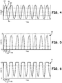
- FIG. 4 illustrates a plot of an oscillating force 81 generated by the actuator 16 where zero force is indicated at 82, a maximum compression force is indicated at 84 and a maximum tension force is indicated at 86.
- FIGS. 5 and 6 illustrate command signals 90, 91, respectively, for the servo valve assemblies 70 and 72 and in particular to metering orifices 31-34 to realize the oscillating of FIG. 4 .
- a compression force is obtained by controlling metering orifices 31 and 32 by reducing the absolute value of the negative voltage applied thereto as illustrated in FIG. 5 during the time period 94, while at the same time metering orifices 33 and 34 are held in the open state by applying a +10 volts thereto as illustrated in FIG. 6 .
- tension loads are generated by the actuator 16 when a control voltage to the metering orifices 31 and 32 is reduced in time period 96, while the control voltage for metering orifices 33 and 34 receive a -10 volts.
- control signals for the metering orifices of servo valve assemblies 18, 70, 72 may need compensation in order to realize the desired force vector from the actuator 16.
- compensation may be needed if fluid flow through the servo valve assemblies in the fully open state exhibits turbulence while in a constricting state fluid flow is more linear.
- Compensation can be provided in any suitable manner such as through (look up tables, polynomial representations or the like implemented for example by the servo valve controller 40).
- Compensation may be embodied in hardware (analog and/or digital circuitry) and/or in software operable on a suitable computing device, such as a digital signal processor, which also is circuitry.
- the circuitry can further include without limitation logic arrays in a system on a chip implementation that integrates some if not all the circuitry and components of a computer or other electronic system that processes digital signals, analog signals, and/or mixed digital and analog signals on the single chip substrate.
Landscapes
- Engineering & Computer Science (AREA)
- Physics & Mathematics (AREA)
- Fluid Mechanics (AREA)
- Mechanical Engineering (AREA)
- General Engineering & Computer Science (AREA)
- Servomotors (AREA)
- Fluid-Pressure Circuits (AREA)
Description
- The discussion below is merely provided for general background information and is not intended to be used as an aid in determining the scope of the claimed subject matter.
- In a conventional configuration of a dual-acting servo actuator, a servo valve meters fluid from a pump to one of two ports of the dual-acting actuator, while also fluidly coupling the other port on an opposite side of a piston in the actuator to a return. In such a system, precise positioning of the piston in the actuator cylinder can be obtained. The actuator thus exhibits characteristics of applying a displacement vector, that being moving a point or object a known distance from an initial to a final position.
- D1 (
US20100024410A1 ) discloses hydraulic system for a machine. The hydraulic system may have an actuator with a first chamber and a second chamber. The hydraulic system may also have a first valve, a second valve, a third valve, and an operator input device displaceable from a neutral position to generate a signal indicative of a desired movement of the actuator. The hydraulic system may further have a controller configured to open the first and third valves by amounts related to the signal to pass fluid, and open the second valve by an amount related to the signal to pass fluid when the signal indicates a desire for increased actuator velocity. The third valve may continue to open during opening of the second valve. - D3 (
US20070044465A1 ) discloses a hydraulic system for a machine as well. The hydraulic control system of D3 has a fluid actuator with first and second chambers, first and second metering valves having valve elements movable to fill and drain the first and second chambers respectively, and at least one fluid sensor configured to generate a load signal indicative of a load on the fluid actuator. The hydraulic control system also has an operator interface device movable to generate a desired velocity signal of the fluid actuator. The hydraulic control system further has a controller in communication with the first and second metering valves, the at least one fluid sensor, and the operator interface device. The controller is configured to move the valve element of the first metering valve to a position based on the desired velocity signal, to determine a desired pressure for the second chamber based on the load signal and a pressure associated with the first chamber, and to move the valve element of the second metering valve to a position based on the determined desired pressure. - This Summary and the Abstract herein are provided to introduce a selection of concepts in a simplified form that are further described below in the Detailed Description. This Summary and the Abstract are not intended to identify key features or essential features of the claimed subject matter, nor are they intended to be used as an aid in determining the scope of the claimed subject matter. The claimed subject matter is not limited to implementations that solve any or all disadvantages noted in the background.
- According to the invention, there is provided a servo actuator system according to claim 1, a method of controlling an actuator system according to claim 11 and a controller according to
claim 15. - Any of the following features can comprise further embodiments when combined with the one of more features of the arrangements and methods above.
- The controller in the second state can control the first metering orifice to inhibit fluid flow therethrough while controlling the second metering orifice to allow fluid flow therethrough at a rate greater than that of a rate through the first metering orifice.
- The servo assembly can comprise four metering orifices and four ports, wherein a unique pair of metering orifices is fluidly connected to each port and each metering orifice controls fluid flow between a unique pair of ports.
- The single servo assembly having the four ports, or multiple, preferably two, conventional
servo valve assemblies - All types of hydraulic and pneumatic actuators (e.g. linear or rotary) can benefit from any of the embodiments described above.
-
-
FIG. 1 is a schematic illustration of a first embodiment of a servo actuator vector generating system to generate a force vector. -
FIG. 2 is a schematic illustration of the embodiment ofFIG. 1 illustrating an applied force state. -
FIG. 3 is a schematic illustration of a second embodiment of a servo actuator vector generating system to generate a force vector comprising two conventional hydraulic servo valves. -
FIG. 4 is a plot of an oscillating force of an actuator. -
FIGS. 5 and 6 are plots of control signals for a servo assembly when realized with two conventional hydraulic servovalves. -
FIG. 7 is a schematic illustration of a rotary actuator. -
FIGS. 1 and2 illustrate a first embodiment of a servo actuator vector generatingsystem 10 in two states of operation. The servo actuatorvector generating system 10 generates a true vector (magnitude and direction) where the actual position of a movable member in an actuator body is indeterminate. In the embodiments ofFIGS. 1-3 , thesystem 10 includes a dual-actingactuator 16 having a piston 12 (movable member) slidable in a cylinder 14 (actuator body). Nevertheless, it should be understood that aspects of the present invention are not limited to linear actuators, but also can be used with arotatory actuator 17 as illustrated inFIG. 7 having a vane 15 (movable member) rotable in ahousing 19. Although described below in detail with respect to alinear actuator 16 to generate a force vector, it should be understood aspects of the invention are equally applicable to therotary actuator 17 to generate a torque, which is also a vector quantity having magnitude and direction. - Referring to
FIGS. 1 and2 , the servo actuatorvector generating system 10 generally comprises dual actingactuator 16, aservo valve assembly 18, and apump 20 having a return indicated at 22. Unlike in a conventional fluidic system (hereinafter specifically referred to as a hydraulic system, but it should be understood aspects of the invention can be used with a pneumatic system as well) where the servo valve selectively fluidly couples the pump to one or the other of the actuator ports, while simultaneously fluidly coupling the other port to the return (as discussed in the background), theservo valve assembly 18 comprises metering orifices that selectively constrict fluid flow therethrough so as to increase pressure on one side of thepiston 12 or the other. - In the embodiment illustrated, the
servo valve assembly 18 includes fourmetering orifices ports port metering orifice -
FIG.1 illustrates a zero force state of theactuator system 10. In this state, allmetering orifices servo valve assembly 18 are preferably completely open, or otherwise open such that fluid flow through theservo valve assembly 18 yields substantially equal pressure on each side of thepiston 12. In this state, fluid flow throughorifices piston 12 is stationary in the cylinder of theactuator 16, fluid flow throughorifices return 22 are also the same. In this state,actuator ports actuator piston 12 is free to move in either direction by any external disturbance applied to the piston 12 (indicated by double arrow 54) although there may be a slight amount of parasitic viscous damping due to fluid porting. In this state, thehydraulic pump 20 is simply pumping hydraulic fluid with no or minimal pressure through theservo valve assembly 18 to thereturn 22. - A controller is schematically indicated at 40 and receives a
command signal 44. A transducer suitable for providing an indication of force applied by theactuator 16 is operably coupled to the actuator. In the exemplary embodiment, the transducer comprises aload cell 46 operably connected to theactuator 16 such as through apiston rod 48 to provide a signal indicative of a force generated by theactuator 16 to thecontroller 40. It should be noted that theload cell 46 can be operably connected to theactuator 16 in another manner such as being operably coupled to thecylinder 14. Likewise, in yet another embodiment pressure transducer(s) can be operably coupled to theactuator 16 so as to measure fluid pressure(s) on one or both sides of thepiston 12. The measured pressure(s) can then be converted or used directly by thecontroller 40 as an indication of force generated by theactuator 16. - The
controller 40 controls the switching assembly 18 (i.e. a proportional valve assembly) selectively operating the switching assembly 18 (typically by controlling movement of a metering spools) so as to cause the metering orifices 31-34, based upon thecommand 44, to selectively constrict, thereby inhibiting or reducing fluid flow therethrough and subsequently increasing the pressure on one side of the metering orifice 31-34. - Stated another way, the
controller 40 is operably coupled to theservo assembly 18 to operate the servo actuator system in a first state and a second state, wherein in the first state thecontroller 40 controls each of the plurality of metering orifices 31-34 such that fluid from thepump 20 flows to thereturn 22 and fluid transfers freely in and out of theports movable member 12, and wherein in the second state thecontroller 40 controls each of the plurality of metering orifices 31-34 such that fluid pressure from thepump 20 causes movement of themovable member 12 in theactuator body 14 while allowing cross flow of fluid between theports - Referring to
FIG. 2 , a tension force state is obtained in theactuator system 10 whereby theactuator piston 12 is forced in a direction indicated byarrow 50. From the zero force state ofFIG. 1 , this is accomplished by controllingmetering orifices metering orifices 31 and 32). This results in a pressure rise at theport 38 caused by constriction of themetering orifices port 36 to thereturn 22. However, since theports double arrow 54, the actual position of thepiston 12 in theactuator cylinder 14 is indeterminate; thus; realizing a true force vector being applied by theactuator 16. - Similarly, a compression force state of the
actuator system 10 is obtained by controllingmetering orifices metering orifices metering orifices 33 and 34). This realizes a pressure rise atport 36 and unrestricted flow fromport 38 to reserve 22, while again maintainingactuator ports port 36 causes force independent of position applied to thepiston 12 in a direction indicated byarrow 56. -
FIG. 3 illustrates use of two conventionalservo valve assemblies servo valve assembly 18 illustrated inFIGS. 1 and2 . In the embodiment ofFIG. 3 , the same reference numerals have been used to identify similar components illustrated inFIGS. 1 and2 . In this embodiment, theservo valve assembly 70 comprises four metering orifices; however, themetering orifices metering orifices FIGS. 1 and2 . Similarly, theservo valve assembly 72 includes four metering orifices; however, themetering orifices metering orifices FIGS. 1 and2 . Thepump 20 ofFIG. 3 is fluidly coupled to themetering orifices pump 20 being fluidly connected tometering orifices FIGS. 1 and2 . Similarly, themetering orifices return 22; theport 36 is fluidly coupled tometering orifices port 38 is fluidly coupled tometering orifices - In the embodiment of
FIG. 3 , the conventionalservo valve assemblies metering orifices metering orifices metering orifices metering orifices -
FIG. 4 illustrates a plot of anoscillating force 81 generated by theactuator 16 where zero force is indicated at 82, a maximum compression force is indicated at 84 and a maximum tension force is indicated at 86. -
FIGS. 5 and 6 illustrate command signals 90, 91, respectively, for theservo valve assemblies FIG. 4 . In particular, a compression force is obtained by controllingmetering orifices FIG. 5 during thetime period 94, while at the sametime metering orifices FIG. 6 . In a similar fashion, tension loads are generated by theactuator 16 when a control voltage to themetering orifices time period 96, while the control voltage formetering orifices - It should be noted that control signals for the metering orifices of
servo valve assemblies actuator 16. In particular, compensation may be needed if fluid flow through the servo valve assemblies in the fully open state exhibits turbulence while in a constricting state fluid flow is more linear. Compensation can be provided in any suitable manner such as through (look up tables, polynomial representations or the like implemented for example by the servo valve controller 40). Compensation may be embodied in hardware (analog and/or digital circuitry) and/or in software operable on a suitable computing device, such as a digital signal processor, which also is circuitry. The circuitry can further include without limitation logic arrays in a system on a chip implementation that integrates some if not all the circuitry and components of a computer or other electronic system that processes digital signals, analog signals, and/or mixed digital and analog signals on the single chip substrate. - Although the subject matter has been described in language specific to structural features and/or methodological acts, it is to be understood that the subject matter defined in the appended claims is not necessarily limited to the specific features or acts described above as has been determined by the courts. Rather, the specific features and acts described above are disclosed as example forms of implementing the claims.
Claims (15)
- A servo actuator system (10) comprising:a dual acting actuator (16,17) comprising:an actuator body (14,19);a movable member (12,15) movable in the actuator body (14,19) to define a first and second chamber on each side of the movable member;a first port (36) fluidly coupled to the first chamber; anda second port (38) fluidly coupled to the second chamber;a fluid pump (20) having a return (22);a servo assembly (18) fluidly coupled to the fluid pump (20), return (22) and the first and second ports (36,38), the servo assembly having a plurality of metering orifices (31, 32, 33, 34); anda controller (40) operably coupled to the servo assembly Z (18) to operate the servo actuator system (10) in a first state and a second state, wherein in the first state the controller (40) controls each of the plurality of metering orifices (31,32,33,34) such that fluid from the pump (20) flows to the return (22) and fluid transfers freely in and out of the ports (36, 38) with an external force applied to the movable member (12,15), and wherein in the second state the controller (40) controls each of the plurality of metering orifices (31,32,33,34) such that fluid pressure from the pump causes a load to be applied to the movable member (12,15) in the actuator body (14,19) while allowing cross flow of fluid between the first and second ports (36,38).
- The servo actuator system (10) of claim 1 wherein the actuator comprises a linear actuator.
- The servo actuator system (10) of claim 1 wherein the actuator comprises a rotary actuator.
- The servo actuator system (10) of claim 1 wherein the controller (40) in the second state controls a first metering orifice to inhibit fluid flow therethrough while controlling a second metering orifice to allow fluid flow therethrough at a rate greater than that of a rate through the first metering orifice.
- The servo actuator system (10) of claim 1 wherein the servo assembly comprises four metering orifices (31,32,33,34) and four ports (18A,18B,18C,18D), wherein a unique pair of metering orifices (31,32,33,34) is fluidly connected to each port and each metering orifice controls fluid flow between a unique pair of ports.
- The servo actuator system (10) of claim 5 wherein the controller (40) in the second state controls a first metering orifice and a second metering orifice to inhibit fluid flow therethrough while controlling a third metering orifice and a fourth metering orifice to allow fluid flow therethrough at a rate greater than that of a rate through the first metering orifice.
- The servo actuator system (10) of any one of claims 1-6 wherein the controller is operably coupled to the servo assembly to control the plurality of metering orifices (21,32,33,34) to generate a vector having magnitude and direction and wherein an actual position of the movable member (12,15) in the actuator body (14,19) is indeterminate while allowing cross flow of fluid between the first and second ports (36,38).
- The servo actuator system (10) of claim 7 wherein the actuator comprises a linear actuator and the vector comprises a force.
- The servo actuator system (10) of claim 7 wherein the actuator comprises a rotary actuator and the vector comprises a torque.
- The servo actuator system (10) of claim 1, wherein in the first state the controller (40) controls each of the plurality of metering orifices (31,32,33,34) such that all metering orifices (31,32,33,34) are open such that fluid flow through the servo valve assembly (18) yields substantially equal pressure on each side of the movable member.
- A method of controlling an actuator system (10) having an actuator body (14,19), a movable member (12,15) movable in the actuator body (14,19) to define a first and second chamber on each side of the movable member (12,15), a first port (36) fluidly coupled to the first chamber, a second port (38)fluidly coupled to the second chamber, a fluid pump (20) having a return (22), and a servo assembly fluidly coupled to the fluid pump (20), return (22) and the first and second ports (36,38), the servo assembly having a plurality of metering orifices (31,32,33,34), the method comprising:selectively operating the actuator system (10) in a first state and a second state,wherein the first state comprises:
controlling each of the plurality of metering orifices (31,32,33,34) with a controller (40) such that fluid from the pump flows to the return (22) and fluid transfers freely in and out of the ports with an external force applied to the movable member (12,15); andwherein the second state comprises:
controlling each of the plurality of metering orifices (31,32,33,34) with the controller (40) such that fluid pressure from the pump causes a load to be applied to the movable member (12,15) in the actuator body (14,19) while allowing cross flow of fluid between the first and second ports (36,38). - The method of claim 11 wherein the actuator comprises a linear actuator.
- The method of claim 11 wherein the actuator comprises a rotary actuator.
- The method of claim 11 wherein the servo assembly comprises four metering orifices (31,32,33,34) and four ports (18A,18B,18C,18D), wherein a unique pair of metering orifices (31,32,33,34) is fluidly connected to each port and each metering orifice controls fluid flow between a unique pair of ports, and wherein controlling each of the metering orifices (31,32,33,34) in the second state comprises:
controlling a first metering orifice and a second metering orifice to inhibit fluid flow therethrough while controlling a third metering orifice and a fourth metering orifice to allow fluid flow therethrough at a rate greater than that of a rate through the first metering orifice. - A controller for use in the servo actuator system (10) according to claim 1, wherein the controller is configured to execute the steps of the method according to claim 11.
Applications Claiming Priority (2)
| Application Number | Priority Date | Filing Date | Title |
|---|---|---|---|
| US13/843,902 US9328747B2 (en) | 2013-03-15 | 2013-03-15 | Servo actuator load vector generating system |
| PCT/US2014/024253 WO2014150796A1 (en) | 2013-03-15 | 2014-03-12 | Servo actuator |
Publications (2)
| Publication Number | Publication Date |
|---|---|
| EP2971796A1 EP2971796A1 (en) | 2016-01-20 |
| EP2971796B1 true EP2971796B1 (en) | 2019-01-30 |
Family
ID=50630996
Family Applications (1)
| Application Number | Title | Priority Date | Filing Date |
|---|---|---|---|
| EP14721051.2A Not-in-force EP2971796B1 (en) | 2013-03-15 | 2014-03-12 | Servo actuator |
Country Status (6)
| Country | Link |
|---|---|
| US (1) | US9328747B2 (en) |
| EP (1) | EP2971796B1 (en) |
| JP (1) | JP6393305B2 (en) |
| KR (1) | KR102205095B1 (en) |
| CN (1) | CN105051379B (en) |
| WO (1) | WO2014150796A1 (en) |
Families Citing this family (3)
| Publication number | Priority date | Publication date | Assignee | Title |
|---|---|---|---|---|
| CN106224310B (en) * | 2016-07-27 | 2018-08-24 | 华侨大学 | A kind of more single plunger pump recombination control cylinder devices of enclosed |
| CN106224312B (en) * | 2016-07-27 | 2018-01-09 | 华侨大学 | A kind of single plunger pump matrix form arranges fluid power system |
| CN106224323B (en) * | 2016-09-13 | 2017-12-01 | 华侨大学 | A kind of closed type hydraulic system of more single plunger pump restructuring control asymmetrical cylinders |
Family Cites Families (17)
| Publication number | Priority date | Publication date | Assignee | Title |
|---|---|---|---|---|
| CH563532A5 (en) * | 1973-03-14 | 1975-06-30 | Buehler Ag Geb | |
| US5960695A (en) * | 1997-04-25 | 1999-10-05 | Caterpillar Inc. | System and method for controlling an independent metering valve |
| GB2332023B (en) * | 1997-12-03 | 2002-07-03 | Caterpillar Inc | System and method for calibrating an independent metering valve |
| JP2000283109A (en) * | 1999-03-31 | 2000-10-13 | Shin Caterpillar Mitsubishi Ltd | Actuator controller |
| US6354185B1 (en) * | 1999-06-17 | 2002-03-12 | Sturman Industries, Inc. | Flow manager module |
| US6467264B1 (en) * | 2001-05-02 | 2002-10-22 | Husco International, Inc. | Hydraulic circuit with a return line metering valve and method of operation |
| US7028599B2 (en) * | 2001-08-10 | 2006-04-18 | Zf Lenksysteme Gmbh | Control device for the continuous drive of a hydraulic control motor |
| US6655136B2 (en) * | 2001-12-21 | 2003-12-02 | Caterpillar Inc | System and method for accumulating hydraulic fluid |
| US6691603B2 (en) * | 2001-12-28 | 2004-02-17 | Caterpillar Inc | Implement pressure control for hydraulic circuit |
| US6718759B1 (en) * | 2002-09-25 | 2004-04-13 | Husco International, Inc. | Velocity based method for controlling a hydraulic system |
| DE10251127B4 (en) * | 2002-11-02 | 2008-11-06 | Zf Lenksysteme Gmbh | control device |
| US7251935B2 (en) * | 2005-08-31 | 2007-08-07 | Caterpillar Inc | Independent metering valve control system and method |
| US7380398B2 (en) | 2006-04-04 | 2008-06-03 | Husco International, Inc. | Hydraulic metering mode transitioning technique for a velocity based control system |
| CN101680208B (en) * | 2007-05-18 | 2013-01-30 | 沃尔沃建筑设备公司 | A method for recuperating potential energy during a lowering operation of a load |
| US8096227B2 (en) * | 2008-07-29 | 2012-01-17 | Caterpillar Inc. | Hydraulic system having regeneration modulation |
| US8752371B2 (en) * | 2010-12-17 | 2014-06-17 | Caterpillar Inc. | Independent metering valve with flow limiter |
| DE112011105277T5 (en) | 2011-05-23 | 2014-04-10 | Parker Hannifin Ab | Method and system for energy recovery |
-
2013
- 2013-03-15 US US13/843,902 patent/US9328747B2/en active Active
-
2014
- 2014-03-12 KR KR1020157027533A patent/KR102205095B1/en active Active
- 2014-03-12 EP EP14721051.2A patent/EP2971796B1/en not_active Not-in-force
- 2014-03-12 WO PCT/US2014/024253 patent/WO2014150796A1/en not_active Ceased
- 2014-03-12 JP JP2016501450A patent/JP6393305B2/en active Active
- 2014-03-12 CN CN201480015901.6A patent/CN105051379B/en active Active
Non-Patent Citations (1)
| Title |
|---|
| None * |
Also Published As
| Publication number | Publication date |
|---|---|
| US9328747B2 (en) | 2016-05-03 |
| WO2014150796A1 (en) | 2014-09-25 |
| US20140260226A1 (en) | 2014-09-18 |
| EP2971796A1 (en) | 2016-01-20 |
| CN105051379A (en) | 2015-11-11 |
| KR20150126018A (en) | 2015-11-10 |
| KR102205095B1 (en) | 2021-01-19 |
| CN105051379B (en) | 2017-06-13 |
| JP2016511381A (en) | 2016-04-14 |
| JP6393305B2 (en) | 2018-09-19 |
Similar Documents
| Publication | Publication Date | Title |
|---|---|---|
| US11131328B2 (en) | Load-sensing multi-way valve with variable differential pressure | |
| US10437269B1 (en) | Electrohydraulic counterbalance and pressure relief valve | |
| US9234532B2 (en) | Velocity control of unbalanced hydraulic actuator subjected to over-center load conditions | |
| US10138915B2 (en) | Method of controlling velocity of a hydraulic actuator in over-center linkage systems | |
| US10927856B2 (en) | Pump-controlled hydraulic circuits for operating a differential hydraulic actuator | |
| US2964059A (en) | Pressure-flow servo valve | |
| US2964023A (en) | Flow force compensated valve | |
| CN112714831B (en) | Hydraulic valve device | |
| US11149758B2 (en) | Control arrangement of a hydraulic system and a method for controlling a hydraulic system | |
| US10281934B2 (en) | Hydraulic control valve with controlled flow and valve safety disable | |
| CN104132016A (en) | Three-way flow valve, load sensing multi-way valve, hydraulic system and construction machinery | |
| US6640833B2 (en) | Fail-freeze servovalve | |
| US9328747B2 (en) | Servo actuator load vector generating system | |
| EP3112697B1 (en) | Hydrostatic systems with shuttle valve for compensating differential flow rate of single-rod actuators | |
| US3511134A (en) | Position-responsive control system for hydraulic actuators | |
| CN116336024B (en) | Electro-hydraulic reversing flow proportional control valve with load flow compensation | |
| CN103015473A (en) | Priority control method of excavator and movable arm to rotation and priority valve | |
| US2904055A (en) | Hydraulic amplifier valve with feedback | |
| US11105433B2 (en) | Pressure reducing-relieving valve | |
| US10408358B2 (en) | Load sensing valve device | |
| US10900502B2 (en) | Direct input pilot operated servo valve | |
| US3070124A (en) | Differential valve | |
| CN203847462U (en) | Multi-flow control valve, chassis support leg hydraulic control system and crane | |
| CN115151734B (en) | Control device and hydraulic system equipped with the control device | |
| US20120205563A1 (en) | Valve arrangement for actuating a load |
Legal Events
| Date | Code | Title | Description |
|---|---|---|---|
| PUAI | Public reference made under article 153(3) epc to a published international application that has entered the european phase |
Free format text: ORIGINAL CODE: 0009012 |
|
| 17P | Request for examination filed |
Effective date: 20150915 |
|
| AK | Designated contracting states |
Kind code of ref document: A1 Designated state(s): AL AT BE BG CH CY CZ DE DK EE ES FI FR GB GR HR HU IE IS IT LI LT LU LV MC MK MT NL NO PL PT RO RS SE SI SK SM TR |
|
| AX | Request for extension of the european patent |
Extension state: BA ME |
|
| DAX | Request for extension of the european patent (deleted) | ||
| STAA | Information on the status of an ep patent application or granted ep patent |
Free format text: STATUS: EXAMINATION IS IN PROGRESS |
|
| 17Q | First examination report despatched |
Effective date: 20171127 |
|
| GRAP | Despatch of communication of intention to grant a patent |
Free format text: ORIGINAL CODE: EPIDOSNIGR1 |
|
| STAA | Information on the status of an ep patent application or granted ep patent |
Free format text: STATUS: GRANT OF PATENT IS INTENDED |
|
| INTG | Intention to grant announced |
Effective date: 20180907 |
|
| GRAS | Grant fee paid |
Free format text: ORIGINAL CODE: EPIDOSNIGR3 |
|
| GRAA | (expected) grant |
Free format text: ORIGINAL CODE: 0009210 |
|
| STAA | Information on the status of an ep patent application or granted ep patent |
Free format text: STATUS: THE PATENT HAS BEEN GRANTED |
|
| AK | Designated contracting states |
Kind code of ref document: B1 Designated state(s): AL AT BE BG CH CY CZ DE DK EE ES FI FR GB GR HR HU IE IS IT LI LT LU LV MC MK MT NL NO PL PT RO RS SE SI SK SM TR |
|
| REG | Reference to a national code |
Ref country code: GB Ref legal event code: FG4D |
|
| REG | Reference to a national code |
Ref country code: CH Ref legal event code: EP |
|
| REG | Reference to a national code |
Ref country code: AT Ref legal event code: REF Ref document number: 1093505 Country of ref document: AT Kind code of ref document: T Effective date: 20190215 |
|
| REG | Reference to a national code |
Ref country code: IE Ref legal event code: FG4D |
|
| REG | Reference to a national code |
Ref country code: DE Ref legal event code: R096 Ref document number: 602014040335 Country of ref document: DE |
|
| REG | Reference to a national code |
Ref country code: LT Ref legal event code: MG4D |
|
| REG | Reference to a national code |
Ref country code: NL Ref legal event code: MP Effective date: 20190130 |
|
| PG25 | Lapsed in a contracting state [announced via postgrant information from national office to epo] |
Ref country code: ES Free format text: LAPSE BECAUSE OF FAILURE TO SUBMIT A TRANSLATION OF THE DESCRIPTION OR TO PAY THE FEE WITHIN THE PRESCRIBED TIME-LIMIT Effective date: 20190130 Ref country code: SE Free format text: LAPSE BECAUSE OF FAILURE TO SUBMIT A TRANSLATION OF THE DESCRIPTION OR TO PAY THE FEE WITHIN THE PRESCRIBED TIME-LIMIT Effective date: 20190130 Ref country code: PT Free format text: LAPSE BECAUSE OF FAILURE TO SUBMIT A TRANSLATION OF THE DESCRIPTION OR TO PAY THE FEE WITHIN THE PRESCRIBED TIME-LIMIT Effective date: 20190530 Ref country code: NO Free format text: LAPSE BECAUSE OF FAILURE TO SUBMIT A TRANSLATION OF THE DESCRIPTION OR TO PAY THE FEE WITHIN THE PRESCRIBED TIME-LIMIT Effective date: 20190430 Ref country code: PL Free format text: LAPSE BECAUSE OF FAILURE TO SUBMIT A TRANSLATION OF THE DESCRIPTION OR TO PAY THE FEE WITHIN THE PRESCRIBED TIME-LIMIT Effective date: 20190130 Ref country code: NL Free format text: LAPSE BECAUSE OF FAILURE TO SUBMIT A TRANSLATION OF THE DESCRIPTION OR TO PAY THE FEE WITHIN THE PRESCRIBED TIME-LIMIT Effective date: 20190130 Ref country code: FI Free format text: LAPSE BECAUSE OF FAILURE TO SUBMIT A TRANSLATION OF THE DESCRIPTION OR TO PAY THE FEE WITHIN THE PRESCRIBED TIME-LIMIT Effective date: 20190130 Ref country code: LT Free format text: LAPSE BECAUSE OF FAILURE TO SUBMIT A TRANSLATION OF THE DESCRIPTION OR TO PAY THE FEE WITHIN THE PRESCRIBED TIME-LIMIT Effective date: 20190130 |
|
| REG | Reference to a national code |
Ref country code: AT Ref legal event code: MK05 Ref document number: 1093505 Country of ref document: AT Kind code of ref document: T Effective date: 20190130 |
|
| PG25 | Lapsed in a contracting state [announced via postgrant information from national office to epo] |
Ref country code: BG Free format text: LAPSE BECAUSE OF FAILURE TO SUBMIT A TRANSLATION OF THE DESCRIPTION OR TO PAY THE FEE WITHIN THE PRESCRIBED TIME-LIMIT Effective date: 20190430 Ref country code: RS Free format text: LAPSE BECAUSE OF FAILURE TO SUBMIT A TRANSLATION OF THE DESCRIPTION OR TO PAY THE FEE WITHIN THE PRESCRIBED TIME-LIMIT Effective date: 20190130 Ref country code: GR Free format text: LAPSE BECAUSE OF FAILURE TO SUBMIT A TRANSLATION OF THE DESCRIPTION OR TO PAY THE FEE WITHIN THE PRESCRIBED TIME-LIMIT Effective date: 20190501 Ref country code: LV Free format text: LAPSE BECAUSE OF FAILURE TO SUBMIT A TRANSLATION OF THE DESCRIPTION OR TO PAY THE FEE WITHIN THE PRESCRIBED TIME-LIMIT Effective date: 20190130 Ref country code: IS Free format text: LAPSE BECAUSE OF FAILURE TO SUBMIT A TRANSLATION OF THE DESCRIPTION OR TO PAY THE FEE WITHIN THE PRESCRIBED TIME-LIMIT Effective date: 20190530 Ref country code: HR Free format text: LAPSE BECAUSE OF FAILURE TO SUBMIT A TRANSLATION OF THE DESCRIPTION OR TO PAY THE FEE WITHIN THE PRESCRIBED TIME-LIMIT Effective date: 20190130 |
|
| REG | Reference to a national code |
Ref country code: DE Ref legal event code: R119 Ref document number: 602014040335 Country of ref document: DE |
|
| PG25 | Lapsed in a contracting state [announced via postgrant information from national office to epo] |
Ref country code: SK Free format text: LAPSE BECAUSE OF FAILURE TO SUBMIT A TRANSLATION OF THE DESCRIPTION OR TO PAY THE FEE WITHIN THE PRESCRIBED TIME-LIMIT Effective date: 20190130 Ref country code: IT Free format text: LAPSE BECAUSE OF FAILURE TO SUBMIT A TRANSLATION OF THE DESCRIPTION OR TO PAY THE FEE WITHIN THE PRESCRIBED TIME-LIMIT Effective date: 20190130 Ref country code: EE Free format text: LAPSE BECAUSE OF FAILURE TO SUBMIT A TRANSLATION OF THE DESCRIPTION OR TO PAY THE FEE WITHIN THE PRESCRIBED TIME-LIMIT Effective date: 20190130 Ref country code: DK Free format text: LAPSE BECAUSE OF FAILURE TO SUBMIT A TRANSLATION OF THE DESCRIPTION OR TO PAY THE FEE WITHIN THE PRESCRIBED TIME-LIMIT Effective date: 20190130 Ref country code: MC Free format text: LAPSE BECAUSE OF FAILURE TO SUBMIT A TRANSLATION OF THE DESCRIPTION OR TO PAY THE FEE WITHIN THE PRESCRIBED TIME-LIMIT Effective date: 20190130 Ref country code: AL Free format text: LAPSE BECAUSE OF FAILURE TO SUBMIT A TRANSLATION OF THE DESCRIPTION OR TO PAY THE FEE WITHIN THE PRESCRIBED TIME-LIMIT Effective date: 20190130 Ref country code: CZ Free format text: LAPSE BECAUSE OF FAILURE TO SUBMIT A TRANSLATION OF THE DESCRIPTION OR TO PAY THE FEE WITHIN THE PRESCRIBED TIME-LIMIT Effective date: 20190130 Ref country code: RO Free format text: LAPSE BECAUSE OF FAILURE TO SUBMIT A TRANSLATION OF THE DESCRIPTION OR TO PAY THE FEE WITHIN THE PRESCRIBED TIME-LIMIT Effective date: 20190130 |
|
| REG | Reference to a national code |
Ref country code: CH Ref legal event code: PL |
|
| PG25 | Lapsed in a contracting state [announced via postgrant information from national office to epo] |
Ref country code: LU Free format text: LAPSE BECAUSE OF NON-PAYMENT OF DUE FEES Effective date: 20190312 Ref country code: SM Free format text: LAPSE BECAUSE OF FAILURE TO SUBMIT A TRANSLATION OF THE DESCRIPTION OR TO PAY THE FEE WITHIN THE PRESCRIBED TIME-LIMIT Effective date: 20190130 |
|
| REG | Reference to a national code |
Ref country code: BE Ref legal event code: MM Effective date: 20190331 |
|
| PLBE | No opposition filed within time limit |
Free format text: ORIGINAL CODE: 0009261 |
|
| STAA | Information on the status of an ep patent application or granted ep patent |
Free format text: STATUS: NO OPPOSITION FILED WITHIN TIME LIMIT |
|
| GBPC | Gb: european patent ceased through non-payment of renewal fee |
Effective date: 20190430 |
|
| PG25 | Lapsed in a contracting state [announced via postgrant information from national office to epo] |
Ref country code: AT Free format text: LAPSE BECAUSE OF FAILURE TO SUBMIT A TRANSLATION OF THE DESCRIPTION OR TO PAY THE FEE WITHIN THE PRESCRIBED TIME-LIMIT Effective date: 20190130 |
|
| 26N | No opposition filed |
Effective date: 20191031 |
|
| PG25 | Lapsed in a contracting state [announced via postgrant information from national office to epo] |
Ref country code: DE Free format text: LAPSE BECAUSE OF NON-PAYMENT OF DUE FEES Effective date: 20191001 Ref country code: LI Free format text: LAPSE BECAUSE OF NON-PAYMENT OF DUE FEES Effective date: 20190331 Ref country code: CH Free format text: LAPSE BECAUSE OF NON-PAYMENT OF DUE FEES Effective date: 20190331 Ref country code: GB Free format text: LAPSE BECAUSE OF NON-PAYMENT OF DUE FEES Effective date: 20190430 Ref country code: IE Free format text: LAPSE BECAUSE OF NON-PAYMENT OF DUE FEES Effective date: 20190312 |
|
| PG25 | Lapsed in a contracting state [announced via postgrant information from national office to epo] |
Ref country code: FR Free format text: LAPSE BECAUSE OF NON-PAYMENT OF DUE FEES Effective date: 20190330 Ref country code: BE Free format text: LAPSE BECAUSE OF NON-PAYMENT OF DUE FEES Effective date: 20190331 Ref country code: SI Free format text: LAPSE BECAUSE OF FAILURE TO SUBMIT A TRANSLATION OF THE DESCRIPTION OR TO PAY THE FEE WITHIN THE PRESCRIBED TIME-LIMIT Effective date: 20190130 |
|
| PG25 | Lapsed in a contracting state [announced via postgrant information from national office to epo] |
Ref country code: TR Free format text: LAPSE BECAUSE OF FAILURE TO SUBMIT A TRANSLATION OF THE DESCRIPTION OR TO PAY THE FEE WITHIN THE PRESCRIBED TIME-LIMIT Effective date: 20190130 |
|
| PG25 | Lapsed in a contracting state [announced via postgrant information from national office to epo] |
Ref country code: MT Free format text: LAPSE BECAUSE OF NON-PAYMENT OF DUE FEES Effective date: 20190312 |
|
| PG25 | Lapsed in a contracting state [announced via postgrant information from national office to epo] |
Ref country code: CY Free format text: LAPSE BECAUSE OF FAILURE TO SUBMIT A TRANSLATION OF THE DESCRIPTION OR TO PAY THE FEE WITHIN THE PRESCRIBED TIME-LIMIT Effective date: 20190130 |
|
| PG25 | Lapsed in a contracting state [announced via postgrant information from national office to epo] |
Ref country code: HU Free format text: LAPSE BECAUSE OF FAILURE TO SUBMIT A TRANSLATION OF THE DESCRIPTION OR TO PAY THE FEE WITHIN THE PRESCRIBED TIME-LIMIT; INVALID AB INITIO Effective date: 20140312 |
|
| PG25 | Lapsed in a contracting state [announced via postgrant information from national office to epo] |
Ref country code: MK Free format text: LAPSE BECAUSE OF FAILURE TO SUBMIT A TRANSLATION OF THE DESCRIPTION OR TO PAY THE FEE WITHIN THE PRESCRIBED TIME-LIMIT Effective date: 20190130 |