EP2969574B1 - Label printer - Google Patents
Label printer Download PDFInfo
- Publication number
- EP2969574B1 EP2969574B1 EP14711728.7A EP14711728A EP2969574B1 EP 2969574 B1 EP2969574 B1 EP 2969574B1 EP 14711728 A EP14711728 A EP 14711728A EP 2969574 B1 EP2969574 B1 EP 2969574B1
- Authority
- EP
- European Patent Office
- Prior art keywords
- cassette
- conductive bar
- locking
- locking element
- set forth
- Prior art date
- Legal status (The legal status is an assumption and is not a legal conclusion. Google has not performed a legal analysis and makes no representation as to the accuracy of the status listed.)
- Not-in-force
Links
- 238000007639 printing Methods 0.000 claims description 52
- 238000000034 method Methods 0.000 claims description 11
- 238000004519 manufacturing process Methods 0.000 claims description 9
- 230000008569 process Effects 0.000 claims description 6
- 230000001419 dependent effect Effects 0.000 claims description 3
- 239000002184 metal Substances 0.000 claims description 2
- 230000007246 mechanism Effects 0.000 description 31
- 238000001514 detection method Methods 0.000 description 25
- 238000003780 insertion Methods 0.000 description 17
- 230000037431 insertion Effects 0.000 description 17
- 238000005520 cutting process Methods 0.000 description 5
- 239000010410 layer Substances 0.000 description 5
- 230000008878 coupling Effects 0.000 description 4
- 238000010168 coupling process Methods 0.000 description 4
- 238000005859 coupling reaction Methods 0.000 description 4
- 230000000717 retained effect Effects 0.000 description 4
- 238000010586 diagram Methods 0.000 description 3
- 230000009471 action Effects 0.000 description 2
- 239000012790 adhesive layer Substances 0.000 description 2
- 230000000694 effects Effects 0.000 description 2
- 230000003993 interaction Effects 0.000 description 2
- 239000000463 material Substances 0.000 description 2
- 238000003825 pressing Methods 0.000 description 2
- 230000001902 propagating effect Effects 0.000 description 2
- 230000001133 acceleration Effects 0.000 description 1
- 239000000853 adhesive Substances 0.000 description 1
- 230000001070 adhesive effect Effects 0.000 description 1
- 230000002411 adverse Effects 0.000 description 1
- 230000004075 alteration Effects 0.000 description 1
- 239000004020 conductor Substances 0.000 description 1
- 238000013461 design Methods 0.000 description 1
- 239000003292 glue Substances 0.000 description 1
- 238000001746 injection moulding Methods 0.000 description 1
- 239000004973 liquid crystal related substance Substances 0.000 description 1
- 238000005259 measurement Methods 0.000 description 1
- 238000012986 modification Methods 0.000 description 1
- 230000004048 modification Effects 0.000 description 1
- 238000004804 winding Methods 0.000 description 1
Images
















Classifications
-
- B—PERFORMING OPERATIONS; TRANSPORTING
- B41—PRINTING; LINING MACHINES; TYPEWRITERS; STAMPS
- B41J—TYPEWRITERS; SELECTIVE PRINTING MECHANISMS, i.e. MECHANISMS PRINTING OTHERWISE THAN FROM A FORME; CORRECTION OF TYPOGRAPHICAL ERRORS
- B41J15/00—Devices or arrangements of selective printing mechanisms, e.g. ink-jet printers or thermal printers, specially adapted for supporting or handling copy material in continuous form, e.g. webs
- B41J15/04—Supporting, feeding, or guiding devices; Mountings for web rolls or spindles
- B41J15/044—Cassettes or cartridges containing continuous copy material, tape, for setting into printing devices
-
- B—PERFORMING OPERATIONS; TRANSPORTING
- B41—PRINTING; LINING MACHINES; TYPEWRITERS; STAMPS
- B41J—TYPEWRITERS; SELECTIVE PRINTING MECHANISMS, i.e. MECHANISMS PRINTING OTHERWISE THAN FROM A FORME; CORRECTION OF TYPOGRAPHICAL ERRORS
- B41J3/00—Typewriters or selective printing or marking mechanisms characterised by the purpose for which they are constructed
- B41J3/407—Typewriters or selective printing or marking mechanisms characterised by the purpose for which they are constructed for marking on special material
- B41J3/4075—Tape printers; Label printers
-
- Y—GENERAL TAGGING OF NEW TECHNOLOGICAL DEVELOPMENTS; GENERAL TAGGING OF CROSS-SECTIONAL TECHNOLOGIES SPANNING OVER SEVERAL SECTIONS OF THE IPC; TECHNICAL SUBJECTS COVERED BY FORMER USPC CROSS-REFERENCE ART COLLECTIONS [XRACs] AND DIGESTS
- Y10—TECHNICAL SUBJECTS COVERED BY FORMER USPC
- Y10T—TECHNICAL SUBJECTS COVERED BY FORMER US CLASSIFICATION
- Y10T29/00—Metal working
- Y10T29/49—Method of mechanical manufacture
- Y10T29/49826—Assembling or joining
-
- Y—GENERAL TAGGING OF NEW TECHNOLOGICAL DEVELOPMENTS; GENERAL TAGGING OF CROSS-SECTIONAL TECHNOLOGIES SPANNING OVER SEVERAL SECTIONS OF THE IPC; TECHNICAL SUBJECTS COVERED BY FORMER USPC CROSS-REFERENCE ART COLLECTIONS [XRACs] AND DIGESTS
- Y10—TECHNICAL SUBJECTS COVERED BY FORMER USPC
- Y10T—TECHNICAL SUBJECTS COVERED BY FORMER US CLASSIFICATION
- Y10T29/00—Metal working
- Y10T29/49—Method of mechanical manufacture
- Y10T29/49826—Assembling or joining
- Y10T29/49863—Assembling or joining with prestressing of part
- Y10T29/49876—Assembling or joining with prestressing of part by snap fit
Definitions
- the present application relates to a label printer, and particularly to a label printer with cassette detection means and to a cassette for use in a label printer.
- Label printers which use a supply of tape, housed in a cassette, received in the label printer.
- the tape comprises an image receiving layer and a backing layer which are secured to one another via an adhesive layer.
- Such label printers include a cutting mechanism for cutting off a portion of the tape after an image has been printed onto the image-receiving layer so that the portion of tape having the image can be used as a label. After the tape has been cut, the cut portion of the tape is pulled from the printer through a slit in the printer housing. The backing layer can then be removed allowing the image-receiving layer to be secured to an object using the adhesive layer.
- Known label printers comprise a cassette-receiving bay in which a cassette is received for printing.
- a printhead is provided in the cassette-receiving bay for co-operating with the supply of tape to print thereon.
- a platen may also be provided in the cassette-receiving bay positioned at a side of the tape opposite to the printhead when the cassette is received in the cassette-receiving bay.
- the printhead co-operates with the platen, with the tape passing therebetween for printing thereon.
- the platen may be driven by a motor for propagating the tape during printing.
- the platen may be freely rotatable and an additional drive roller may be provided for driving the tape during printing.
- a platen may be provided within the cassette.
- the tape cooperates with a surface of the platen.
- the platen in the cassette co-operates with a drive mechanism in the cassette-receiving bay for driving the tape during printing.
- the platen is freely rotatable and an additional drive roller may be provided for driving the tape.
- the printhead in the cassette-receiving bay co-operates with the platen in the cassette with tape passing therebetween for printing thereon.
- the printhead is moveable between a non-printing position and a printing position.
- the platen is moveable between a non-printing position and a printing position.
- both the platen and printhead are movable so as to have non-printing and printing positions.
- the tape may be of a direct thermal type on which printing is achieved by direct application of heat from printing elements on the printhead.
- an ink ribbon may be provided, whereby ink is transferred from the ribbon to an image receiving tape by application of heat to the ink ribbon via printing elements on the printhead.
- the cassette may include a roll of die cut labels rather than a continuous tape.
- WO 2006/013466 discloses a cassette locking and ejecting arrangement for a label printer apparatus.
- a label printer comprising a cassette-receiving bay in which a tape cassette is inserted, is provided.
- the cassette receiving bay is provided with a plurality of spring-loaded ejecting members for ejecting a cassette from the cassette-receiving bay.
- a pair of locking members hold the cassette in place against the biasing force exerted by the ejecting members.
- the locking members are disengaged from the cassette allowing the cassette to be pushed out of the cassette-receiving bay by the force exerted by the ejecting members.
- WO 2006/013466 has a pair of locking members which are biased, by means of a spring, towards a locking position so as to lock a cassette inserted into the cassette receiving bay in place.
- the locking members will be moved against the biasing force of the spring so as to release the cassette. Accordingly, when a user subsequently resumes printing with the label printer apparatus, the cassette will not be properly locked in the cassette receiving bay in the correct position for printing, and printing will be adversely effected or impossible.
- US 2011/103871 discloses a label printer cassette having at least one locking portion for engaging with a co-operating locking element of a tape printer when the cassette is correctly inserted in the printer.
- the locking portion comprises a conductive area.
- said cassette comprises a ledge portion projecting from a side of said cassette, said ledge portion comprising said conductive bar.
- said cassette comprises a recess in said side, wherein said ledge portion is located in said recess.
- said cassette comprises a second conductive bar.
- said second conductive bar is located on a side of said cassette opposite from said conductive bar.
- said cassette comprises a base, a top, and at least one side extending between said base and said top, wherein said conductive bar is comprised on said at least one side.
- said bar comprises a metal.
- said bar is cylindrical in cross section.
- a main body portion of said cassette comprises a plastic material.
- said supply roll comprises at least one of a supply of image receiving tape and a supply of ink ribbon.
- a label printing apparatus comprising: a cassette receiving bay adapted to receive a cassette, said cassette receiving bay having a base, an opening opposite the base, and side walls extending between the base and the opening; a cassette locking mechanism comprising at least one locking element having a locking position for engagement with a cassette inserted into said cassette receiving bay; and cassette detection means operable to determine whether said at least one locking element is engaged with a cassette inserted into the cassette receiving bay; wherein the cassette detection means comprises at least one conductive surface disposed on the at least one locking element; wherein the locking element comprises a first surface for engaging a surface of a cassette as the cassette is inserted into the cassette receiving bay so as to cause deflection of said locking element, and a second surface arranged to contact a conductive portion of the cassette for retaining the cassette when it is correctly inserted in the cassette receiving bay.
- said first and second surfaces of said locking element are ramped.
- first and second ramped surfaces converge towards a connecting portion connecting said first and second ramped surfaces.
- said locking element is configured to be deflected by engagement of said locking element with a ramped or ribbed surface of said cassette, as said cassette is inserted in said label printing apparatus.
- said locking element comprises at least one shoulder portion adjacent said first ramped portion.
- said conductive surface extends over said second ramped surface, said shoulder portion and over a rear side of said locking element towards a terminal of said conductive surface.
- said conductive surface comprises a concavely curved portion adjacent said second ramped surface.
- a method of manufacturing a cassette for a label printing apparatus comprising: providing a cassette main body having a base, a top, and sides extending between said base and said top; and inserting a conductive bar into a receiving portion of said cassette, such that said conductive bar extends along said cassette in a direction perpendicular to a rotational axis of a supply roll housed in said cassette.
- said conductive bar is manually inserted into said receiving portion.
- said conductive bar is inserted into said receiving portion as part of an automated process.
- said conductive bar is a friction fit in said receiving portion.
- said friction fit comprises one of a push-fit and a snap-fit.
- the label printer 2 comprises a body 4, a lid (or cover) 6 and a cassette-receiving bay 8.
- the cassette-receiving bay 8 has an opening in a top portion of the body for vertical insertion of a cassette. Alternatively the opening could be on another side of the label printer 2.
- the lid 6 is hinged for closing over the top opening.
- the lid (or cover) may be a detachable lid which is completely detachable from the body 4 of the label printer 2 when in an open position.
- the cassette-receiving bay 8 comprises a recess forming an opening for receiving a cassette.
- the recess is formed by a base 10 and sides 12 extending from the base 10 to the top opening.
- a platen 14 and a printhead 16 are provided in the cassette-receiving bay 8.
- the printhead 16 is movable towards the platen 14 whereby, during printing, the printhead 16 co-operates with the platen 14, with tape passing therebetween for printing thereon.
- the platen 16 is driven by a motor (not shown) for propagating the tape during printing.
- An ink ribbon take-up sprocket 18 extends from the base 10 of the cassette-receiving bay 8 for cooperating with an ink ribbon take-up spool of a cassette when inserted into the cassette-receiving bay 8.
- the sprocket 18 is driven by a motor (not shown) for winding the ink ribbon around the ink ribbon take-up spool during printing.
- a slit 19 is provided in the body 4 of the label printer forming an exit through which the tape passes after printing.
- a cutting mechanism 21 is provided adjacent the exit slit 19 for cutting off the printed portion of tape to provide a printed label.
- a first ejector element 24 is visible on a side-wall of the cassette-receiving bay 8. Also visible in Figure 1 is a locking element 26 of a locking mechanism (which is not visible) on the left hand side of the cassette-receiving bay 8. The locking element 26 is described in more detail below.
- An actuator button 29 is provided on the surface of the body 4 for actuating the locking mechanism.
- a second ejector element 28 of a second ejector mechanism (which is not visible) is shown on the opposite side wall of the cassette receiving bay 8 to the first ejector element 24.
- a third ejector element 30 of a third ejector mechanism (which is not visible) is positioned on the right hand side of the cassette receiving bay 8.
- a second locking element 32 of the locking mechanism (which is not visible) is positioned on the right hand side of the cassette-receiving bay 8.
- each of the locking and ejector elements 24, 26, 28, 30, 32 are provided at the sides of the cassette-receiving bay 8 and extend into the cassette-receiving bay 8 through openings in the sides for interaction with an inserted cassette.
- Each locking element 26, 32 comprises a projection 34 and an elongate element 36 extending in a direction from the base 10 towards the top opening of the cassette-receiving bay 8.
- the projection 34 is at a top end of the elongate element 36 and extends towards a central portion of the cassette-receiving bay 8 through a corresponding opening in the side wall 12 of the cassette-receiving bay 8.
- Each projection 34 has a sloped upper surface for cooperating with a cassette inserted into the cassette-receiving bay 8 for moving the locking element from a locking position to an unlocked position.
- One of the side walls of the cassette-receiving bay 8 has a portion 39 projecting into the cassette-receiving bay 8 forming a guide for a corresponding recess in a cassette when inserted into the cassette-receiving bay 8.
- the locking element 32 is positioned in an opening in the guide 39 and extends therefrom into the cassette-receiving bay 8 thereby forming a combined guiding and locking arrangement.
- the locking elements 26 and 32 shown in Figure 1 , 2 , 3 and 5 show one example of the structure of a locking element, and it should be appreciated that the locking element can take the form of other configurations (see for example Figures 27 to 29 ).
- Each ejecting element 24, 28, 30 extends from the side wall of the cassette-receiving bay 8 part way into the cassette-receiving bay 8 and has a free end unconnected to any other structural elements.
- the ejector elements 24, 28, 30 comprise an elongate element 38 extending in a perpendicular direction relative to the side wall through an opening in the side wall.
- Figures 9, 10 , 11 and 12 illustrate the positions of the locking and ejector elements 24, 26, 28, 30, 32 when the cassette is being inserted into the cassette-receiving bay 8.
- the cassette is not shown for clarity.
- the cassette contacts the locking and ejector elements 24, 26, 28, 30, 32.
- the projections 34 of the locking elements 26, 32 have sloped upper surfaces such that as the cassette is inserted the locking elements 26, 32 are pushed backwards by the cassette into corresponding openings in the side walls 12.
- the locking elements 26, 32 are in their unlocked position.
- the locking elements 26, 32 are spring loaded to move into the locking position when the cassette is fully loaded as shown in Figures 7 and 8 .
- the locking elements 26, 32 prevent the cassette from moving in an upward direction by interacting with locking features in the cassette.
- the ejectors 24, 28, 30 are spring loaded and cooperate with an underside of the cassette.
- the ejector button 29 is actuated by a user pressing down on it, which unlocks the mechanism by moving the locking elements 26, 32 backwards into their corresponding openings in the side walls 12 of the cassette-receiving bay 8.
- the cassette is thus released and the ejectors 24, 28, 30 push the cassette upwards for easy removal from the printer 2.
- the ejectors 41 each comprise a body portion 40. Adjacent to a first edge 40a thereof, the body portion 40 has hole 42 formed therethrough, the axis of the hole arranged so as to be parallel to the first edge 40a of the body portion 40.
- the hole 42 has a circular cross-section.
- the body portion 40 comprises a rack portion 44.
- An ejector element 46 extends perpendicularly from the plane of the body portion 40, which extends between the first and second edges 40a, 40b, from a point adjacent to the first edge 40a of the body portion 40, i.e.
- the ejector element 46 is arranged so as to extend through a slit (not shown) in the side wall 12 of the cassette-receiving bay 8.
- Each ejector 41 further comprises a biasing member 48 at the bottom end of the first edge 40a of the body portion 40.
- the biasing member 48 extends in the plane of the body portion 40 perpendicular to the axis of the hole 42.
- the biasing member 48 is coupled to one end of an expansion spring 50, for biasing the ejector element 46 towards the top end of the corresponding slit (not shown) in the side wall 12 of the cassette-receiving bay 8.
- the top end of the slit in the side wall 12 is the end adjacent to the top opening of the cassette receiving bay 8, with the bottom end of the slit being that which is adjacent to the base 10 of the cassette receiving bay 8.
- the body portion 40 of the ejector mechanism 41 is mounted on a shaft 52, which extends through the hole 42 in the body portion 40.
- a damper 54 is disposed adjacent to the rack portion 44 of the body portion 40.
- the damper 54 comprises a pinion (or gear) 56 which is rotatably mounted to a damper mount part 58.
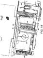
- Figure 14 shows an ejector mechanism 41 of the label printer 2.
- the ejector mechanism 41 comprises an ejector housing 60.
- the ejector housing 60 is approximately cylindrical in shape.
- the shaft 52 of the ejector mechanism 41 is disposed so as to be co-axial with the ejector housing 60.
- the body portion 40 is slidably mounted within the ejector housing 60, by means of the shaft 52 passing through the hole 42 formed at the first end 40a of the body portion 40.
- the ejector housing 60 comprises a first elongate opening along its length (not shown).
- the first elongate opening of the ejector housing 60 is aligned with a corresponding slit formed in a side wall 12 of the cassette receiving bay 8.
- the ejector element 46 of the ejector mechanism 41 protrudes into the cassette-receiving bay 8 through the first elongate opening and through the slit in the side wall 12, so as to interact with a cassette.
- the ejector housing 60 further comprises a second elongate opening (not shown) through which the biasing member 48 of the body portion 40 extends. As can be seen in Figure 14 , the biasing member 48 is attached to the lower end of the spring 50, i.e. the end of the spring 50 closest to the base 10 of the cassette receiving bay 8.
- the ejector housing 60 comprises a fixed extension 62 disposed at an upper end of the housing 60, adjacent to the top of the second elongate opening.
- the upper end of the spring 50 is attached to the fixed extension 62. Accordingly the spring 50 acts so as to bias the body portion 40 of the ejector mechanism 41 towards the upper end of the housing 60.
- the ejector housing 60 further comprises a third elongate opening (not shown), through which the rack portion 44 at the second edge 40b of the body portion 40 extends. The third elongate opening is aligned relative to a damper 54, such that the rack portion 44 meshes with the pinion 56 of the damper 54.
- the locking mechanism comprises the two locking elements 26, 32.
- the locking elements 26, 32 each comprise an elongate element 36 and a projection 34.
- Each projection 34 has a sloped upper surface for cooperating with a cassette inserted into the cassette-receiving bay 8 for moving the locking elements 26, 32 from the locking position to the unlocked position.
- the locking elements 26, 32 are coupled together by an actuating bar 64.
- Each of the locking elements 26, 32 is coupled to the actuating bar 64 by a respective coupling member 66, 68 extending in a perpendicular direction relative to the locking element.
- the locking elements 26, 32 have respective centres of rotation 70, 72 on opposite sides of the actuating bar 64 to each other.
- the centres of rotation 70, 72 comprise pivot points attached to the printer body 4.
- a return spring 74 is provided for biasing the locking elements 26, 32 towards the locking position.
- the actuating bar 64 has a centre of rotation 76, which also comprises a pivot point attached to the printer body 4.
- the first locking element 26 is rotatably coupled to the actuating bar 64 by means of a slot 78, provided in the distal end of the coupling member 66 relative to the first locking element 26, which cooperates with a pin 80 provided at a first end 65 of the actuating bar 64.
- the second locking element 32 is similarly rotatably coupled to a second end of the actuating bar 64.
- the ejector button 29 is disposed adjacent to the cassette-receiving bay 8, so as to be pressed by a user to eject a cassette from the cassette-receiving bay 8 when the lid 6 is open and a cassette is inserted.
- the ejector button 29 comprises an actuator part 82.
- the upper end of the actuator part (not shown) has a circular cross-section and extends through an opening in the upper surface of the label printer 2, such that it can be pressed by a user.
- the lower end of the actuator part 82 comprises first and second tubular portions 83, 84 and a flange part 85 disposed therebetween.
- the flange part 85 of the ejector button actuator part is angled at the lower end thereof, at an angle of approximately 45°.
- First and second button guide shafts 86, 87 are mounted to the printer body 4 and pass through the first and second tubular portions 83, 84 of the actuator part 82, respectively, so as to guide the motion of the actuator part 82 when pressed by a user.
- First and second eject button springs 88, 89 are disposed on the first and second guide shafts 86, 87, respectively, so as to bias the actuator part 82 towards the top of the label printer 2.
- the first locking element 26 comprises cassette detection.
- the cassette detection comprises first and second contact pads 302, 304, which are connected to cassette detection circuitry 310 by means of respective first and second conduction connections such as wires, conductive pads, conductive material, etc. 306, 308.
- first and second conduction connections will be referred to as wires in the following but as will be appreciated this is by way of example only and the wires can be replaced by any other suitable conduction arrangement.
- the first and second contact pads 302, 304 are disposed on the lower surface (that is the surface which engages the cassette) of the projection 34 of the first locking element 26.
- the first wire 306 is connected to the first contact pad 302 at one end and extends from the first contact pad 302 along the surface of the elongate element 36 and is connected at the other end to the cassette detection circuitry 310.
- the second wire 308 connects the second contact pad 304 to the cassette detection circuitry 310.
- the second locking element 32 is similarly provided with first and second contact pads 302, 304 which are connected to the cassette detection circuitry 310 via first and second wires 306, 308, respectively.
- a further example of a locking element is shown in Figures 27 to 29 .
- the cassette 400 comprises a base 402, a top 404, and sides 406, 408, 410 and 412 connecting the base 402 to the top 404.
- the cassette 400 also comprises a recess 414 for accepting a print head when the cassette 400 is inserted in a label printer.
- the cassette 400 also carries a supply of image receiving tape 416 and ink ribbon 418. After printing the image receiving tape passes out of the cassette via outlet 420 and the ink ribbon is taken up in the cassette 400 on ink ribbon take up spool 422.
- Side 406 of the cassette comprises a recess 424.
- the recess 424 comprises a locking portion shown generally at 425.
- the locking portion 425 comprises a ledge portion 426 upon which is mounted an elongate conductive bar 428.
- the conductive bar 428 may be cylindrical or of any other cross-section such as square, rectangular, hexagonal etc.
- the conductive bar 428 is retained in seat portions, or receiving portions, 430 and 432 at either side of ledge 426. In the region between the seats 430 and 432 the conductive bar 428 is spaced from the surfaces of the cassette 400 and the ledge 426. That is the conductive bar 428 spans a trough portion 434 of ledge 426.
- a recess portion 436 of cassette 400 is more clearly shown in Figure 19 .
- recess 436 also comprises a locking portion shown generally at 437 comprising a ledge portion 438.
- Ledge portion 438 supports a second elongate conductive bar 440 which is retained at either end in seats, or receiving portions, 442 and 444 of ledge 438.
- the conductive bar 440 may be of any cross sectional shape such as cylindrical, square, rectangular, hexagonal etc.
- the conductive bar 440 spans a trough portion 446 of ledge 438.
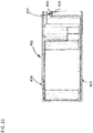
- Figures 20 and 21 are sectional views of the cassette 400.
- Figure 20 shows the positioning of the conductive bar 428 on the ledge 426. Whilst Figure 20 shows the top surface of the bar 428 flush with the upper edge of the ledge 426 (i.e. in seats 432 and 430), it should be appreciated that in alternative embodiments the ends of the conductive bar 428 may sit proud of or be recessed in the seats 430 and 432.
- Figure 21 shows the positioning of the conductive bar 440 in the ledge 438. Again it should be appreciated that although the ends of the conductive bar 440 are shown as flush with the seats 440 and 442 of the ledge 438, in alternative embodiments the conductive bar 440 may sit proud of or be recessed in the seats 442 and 444.
- FIG 21A shows a further embodiment of a cassette 400'.
- Conductive bar 428' is located on a ledge portion 426'. More particularly the conductive bar 428' is located between receiving portions 430' and 432'.
- the conductive bar 428' may be a friction fit with the receiving portions 430' and 432', such as a push-fit or a snap-fit.
- the conductive bar 428' may be attached to the receiving portions 430' and 432' with an adhesive, such as glue.
- the conductive bar 428' can be in-moulded during an injection moulding process.
- Cassette 400' also comprises rib 427' which protrudes from the upper surface of ledge 426'.
- the rib 427' is positioned proximate to conductive bar 428'.
- the rib 427' has a longitudinal axis which extends laterally of, and parallel to, longitudinal axis of conductive bar 428'.
- the rib 427' may be of any cross-sectional shape such as square, circular, semicircular etc.
- the rib 427' may act as a guide to help ensure that the conductive bar 428' is correctly located between receiving portions 430' and 432' when inserted.
- the rib 427' also acts as a wall to stop the conductive bar 428' from springing out of the receiving portions 430' and 432'.
- the rib 427' also prevents the conductive bar 428' from being removed easily from the cassette, and therefore may prevent inadvertent removal of the conductive bar 428'.
- the rib 427' is slightly spaced from the conductive bar 428'.
- the rib 427' engages the conductive bar 428'.
- the conductive bar 428' is frictionally engaged with receiving portions 430' and 432' and rib 427', once correctly inserted.
- the conductive bar 428' is spaced from a sidewall of cassette 400' by a distance Z. It should be appreciated that Z can be of any distance, including zero (in which case the conductive bar 428' will also be in contact with the sidewall of the cassette).
- each ejector mechanism 41 When there is no cassette inserted in the cassette-receiving bay 8, the spring 50 of each ejector mechanism 41 is in an unextended state and, accordingly, each ejector element 24, 28, 30 is disposed at the top end of the corresponding slot in the side wall 12 of the cassette-receiving bay 8.
- the locking elements 26, 32 of the locking mechanism are biased towards the locking position, by means of the return spring 74 acting on the actuating bar 64.
- each ejector element 24, 28, 30 When a cassette is inserted into the cassette receiving bay 8, the base of the cassette presses down on each ejector element 24, 28, 30. This, in turn, causes the body portion 40 of each ejector to move downwards along the shaft 52 and causes the spring 50 to extend. As the body portion 40 moves downwards, the rack portion 44 is meshed with the pinion 56 of the damper 54. Accordingly, the pinion 56 of the damper 54 is rotated as the cassette is inserted and provides a resistance to the force applied to the cassette by a user who inserts the cassette into the cassette receiving bay 8.
- the resistance provided by the pinion 56 engaging with the rack portion 44 is preferably selected so as not to be so great that a user requires excessive force to insert a cassette into the cassette-receiving bay 8, which could damage components of the ejector mechanisms.
- the locking elements 26, 32 engage with corresponding portions of the cassette, so as to hold the cassette in the cassette-receiving bay 8 against the force exerted on the base of the cassette by the ejector elements 24, 28, 30. More specifically, the projection 34 of the first locking element 26 engages with conductive bar 428 of the cassette 400. Accordingly, the first and second contact pads 302, 304 of the first locking element 26 are in contact with the conductive bar 428. The conductive bar 428 is dimensioned such that a conductive connection between the first and the second pad is created when the locking element engages the conductive bar 428. Similarly, the projection 34 of the second locking element 32 engages with conductive bar 440.
- first and second contact pads 302, 304 of the second locking element 32 are in contact with the conductive bar 440 of the cassette 400.
- the conductive bar 440 is dimensioned such that a conductive connection is created between the first and the second pad when the locking element engages the locking member.
- the cassette detection circuitry 310 may detect the engagement of the first and second locking elements 26, 32 with the conductive bars 428 and 440 of the cassette, by measuring the resistance, voltage or current, or by substituting the measured value into an analog or digital measurement between the first and second contact pads 302, 304 of each locking element 26, 32. For example, if a voltage is applied to the first contact pad then a current will flow between the first and second contact pads 302, 304, via the respective conductive bars 428 and 440. Accordingly, the cassette detection circuitry can determine whether the first and second locking elements 26, 32 are properly engaged with the cassette by detecting the flow of the current.
- the cassette detection circuitry determines that the cassette is correctly inserted and printing may be commenced.
- the cassette detection circuitry determines that the cassette is correctly inserted and printing may be commenced.
- it is possible that one of the locking elements will not be properly engaged with the cassette if, for example, the cassette is inserted with an uneven force. In this case, no current will flow between the first and second contact pads 302, 304 of the second locking element 32 because the first and second contact pads 303, 304 are not in contact with the conductive bar 440 of cassette 400.
- the cassette detection circuitry will determine that the second locking element 32 is not engaged properly with the cassette.
- a label printer controller may control the label printer to prevent printing. Furthermore, the controller may inform a user via a display means (not shown), which may be a liquid crystal display, that the cassette is not properly inserted.
- the cassette detection circuitry is operable to determine which of the one or more locking element 26, 32 is not properly engaged with the cassette. Accordingly, the controller may inform the user via the display means, as to which locking element/s are not engaged with the cassette and may further inform the user as to what action is required in order to correctly insert the cassette.
- control may display a diagram similar to Figure 22(ii) on the display means, to indicate which side of the cassette must be pressed in order for the cassette to be inserted properly.
- Such an indication may also be displayed in the event that one or more of the locking elements disengages from the cassette, for example, as a result of the printer being dropped and subjected to a sudden impact.
- the latter may also be displayed in the event that one or more of the locking elements disengages from the cassette during transport of the label printer with a cassette installed.
- the cassette detection circuitry detects the engagement of the locking elements 26, 32 with the cassette and the controller enables printing to commence.
- a cassette may be ejected by a user pressing the eject button 29.
- the downward movement of the actuating part 82 causes the angled flange part 85 to push against the first end 65 of the actuating bar 64.
- the actuating bar 82 rotates around its centre of rotation 76 in an anti-clockwise direction (as viewed). Accordingly, the coupling member 66 of the first locking element 26 rotates clockwise around centre of rotation 70, thereby moving the first locking element 26 to the unlock position.
- the coupling member 68 of the second locking element 32 rotates anti-clockwise around centre of rotation 72, thereby moving the second locking element 32 to the unlock position.
- the cassette With the locking elements 26, 32 in the unlock position, the cassette is free to move under the force exerted by the ejector elements 24, 28, 30.
- the expansion springs 50 of the ejector mechanisms 41 contract, the ejector elements 24, 28, 30 move up their corresponding slits in the side walls 12 of the cassette-receiving bay 8 and push the cassette out of the cassette receiving bay 8.
- the rack portion 44 of each ejection mechanism 41 is meshed with the pinion 56 of the corresponding damper 54. Accordingly, the engagement of the rack portion 44 and the pinion 56 provides a resistance to the upward movement of the ejector elements 24, 28, 30.
- the acceleration of an ejector element in the upward direction under the force of the expansion spring 50 is reduced.
- the cassette is thus gradually ejected from the cassette-receiving bay 8.
- the degree of resistance provided by the pinion 56 of the damper 54 may be determined by the viscosity of oil used to lubricate the pinion with respect to the damper mount part 58.
- only one of the locking elements may be provided with contact pads for detecting engagement of that particular locking element with the cassette. In this case the user may be informed of whether or not the locking element provided with the contact pads is properly engaged with the cassette.
- the one locking element provided with contact pads is positioned adjacent the print head such that it is detected that the cassette is positioned correctly adjacent the position where the image is formed on the tape.
- the label printer is only provided with a single locking element for retaining a cassette in the cassette receiving bay. In this case, the single locking element could be provided with contact pads for detecting the insertion of a cassette as described above.
- the single locking element is positioned adjacent the print head.
- the first locking element 26 is provided with a single contact pad 302 which is connected to cassette detection circuitry 310 by conductive connection 306, which can of course take any suitable format such as a wire or the like.
- the second locking element 32 is provided with a single contact pad which is connected to the cassette detection circuitry 310 by means of a conductive connection such as a wire 306 or the like.
- the cassette may be provided with a conductive connection between the two conductive locking elements of the cassette. Correct insertion of the cassette will result in the completion of a circuit.
- a cassette according to another embodiment is shown in Figure 24 .
- the cassette 500 comprises a base 502, top 504 and a side 506 connecting the base 502 to the top 504.
- a supply of image receiving tape 516 is contained within the cassette 500 and after printing exits the cassette via outlet 520.
- the cassette 500 also comprises a recess 514 for accepting a print head when the cassette is inserted in a label printer.
- the cassette 500 also comprises a locking portion shown generally at 525, similar to the locking portion of the cassette shown in Figures 18 and 19 .
- the locking portion 525 comprises a rib or ledge 526 which extends around side 506 of the cassette 500.
- Seats 530 and 532 sit on an upper surface of ledge 526, and a conductive bar 528 is supported at either end by the seats, or receiving portions, 530 and 532.
- the locking portion 525 is shown in more detail in Figures 25 and 26 .
- the locking portion 525 also comprises a trough portion 534 which is spanned by the conductive bar 528 between the seats 530 and 532.
- the conductive bar 528 maybe of any cross sectional shape.
- Figure 26 shows a cross section through the cassette 500. Between the seats 530 and 532 a lower edge of the conductive bar 528 rests in the trough 534, with an upper portion of the conductive bar sitting proud of the trough 534. In another embodiment the conductive bar may be spaced from the surfaces of the cassette 500 in the region between the seats 530 and 532.
- FIG 32 shows a cassette according to a further embodiment.
- the cassette 700 comprises a base 702, a top 704 and sides 706, 708, 710 and 712.
- the cassette also comprises a printhead recess 714.
- Certain features of the cassette are symmetrical about a centre line 715.
- a locking portion 725 is symmetrical about centre line 715. This allows the cassette 700 to be used in two types of cassette receiving bays, where those cassette receiving bays mirror each other.
- the locking portion 725 comprises a first conductive bar 728 which is received at either end by seat portions or receiving portions 730 and 732.
- the conductive bar 728 is positioned above a ledge portion 726, upon which is mounted elongate rib 727.
- the locking portion 725 also comprises a second conductive bar 760 which is received at either end by seat portions or receiving portions 762 and 764, and elongate rib 766 which is positioned adjacent conductive bar 760.
- Figure 33 is a plan view of the cassette 700.
- the conductive bar 728 is visible from this view. It can also be appreciated that a further locking portion 711 comprising one or more conductive bars (similar to the side shown in Figure 32 ) is also present on side 710.
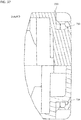
- Figure 33A is a sectional view of cassette 700 through section X-X. In this figure the conductive bars are present in the cassette. See Figure 34 for detail A.
- Figure 33B is a sectional view of cassette 700 through section X-X. In this figure the conductive bars are omitted. See Figure 35 for detail B.
- Figure 33C is a sectional view of cassette 700 through section Y-Y. In this figure the conductive bars are present in the cassette. See Figure 36 for detail C.
- Figure 33D is a sectional view of cassette 700 through section Y-Y. In this figure the conductive bars are omitted. See Figure 37 for detail D.
- Figure 34 shows detail A of Figure 33 .
- Detail A shows a sectional view through conductive bars 776 and 778 of locking portion 711.
- Conductive bar 776 is received in a receiving portion or seat portion 780, and conductive bar 778 is housed in receiving portion or seat portion 782.
- FIG 35 shows detail B.
- the conductive bars 776 and 778 are omitted for clarity.
- the receiving portion 780 tapers up to a back wall 784 which extends vertically to meet top 704 of the cassette. That is the back wall 784 joins to tapering wall 786 which tapers down to the region where the conductive bar 776 is housed (as shown in Figure 34 ).
- the receiving portion 780 also comprises region 788 which has a face 790 which also tapers to meet the region where the conductive bar 776 is housed.
- tapering walls facilitate insertion of the conductive bar 776.
- the tapering surfaces 786 and 790 act as a guide to smoothly and correctly locate the conductive bar 776 as it is being inserted.
- the back wall 784 being laterally spaced from where the conductive bar 776 is located also provides room for a user's hand or automated item of machinery when inserting the conductive bar 776 (this can be further appreciated from Figure 42 ).
- receiving portion 782 is similarly structured. This structure also applies to other regions of the cassette where conductive bars are located, for example seat portions 730, 732, 762 and 764.
- Figure 36 is a view of detail C from Figure 33C . This Figure is through section Y-Y, approximately midway along conductive bars 776 and 778. This Figure clearly shows ribs 792 and 794.
- Figure 37 is also through section Y-Y, with the conductive bars 776 and 778 omitted.
- the ribs 792 and 794 are also visible in Figure 37 . These ribs act as per the rib 427' discussed in Figure 21A , and the ribs 727 and 766 as described in relation to Figure 32 .
- Locking elements for locking a cassette in a label printer have been discussed earlier, for example locking elements 26 and 32 shown in Figures 3 , 5 , 17 , 22 and 23 etc.
- FIGS 27 to 29 show an alternative embodiment of a locking element.
- the locking element is shown generally at 626 in Figure 27 .
- the locking element 626 comprises conductive tracks 628 and 630 for engaging with a corresponding conductive member on a cassette.
- the locking element 626 also comprises a ramp portion 632 which protrudes upwardly from the locking portion. Either side of the ramped portion 632 are shoulder portions 642 and 644 upon which conductive tracks 628 and 630 are respectively mounted.
- the locking element 626 also comprises a main body portion 634 in the form of an upstanding post.
- the conductive track 628 extends from a front side of the locking element 626, along a ramped portion 629, across a top surface of the locking element over shoulder 642, and then down a rear side 637 of the locking element 626.
- the conductive track 628 can therefore be considered to extend from a first point 636 to a terminal 638 where it may connect with printer circuitry.
- the conductive track 628 also comprises a concavely curved portion 640 proximate to the first end 636. The concavely curved portion may assist with assembly.
- the conductive track 630 (not shown in Figure 28 ) extends in the same manner as conductive track 628.
- connection portion 645 of locking element 626 slots into a corresponding aperture in a label printing apparatus so that the locking element 626 can be retained therein.
- projections 650 and 652 which project through holes in the conductive track.
- the projections 650 and 652 are for assembling the conductive tracks on the body portion by a heat stake process. During the heat stake process the heat stake projections 650 and 652 are melted.
- Figures 30 and 31 show the interaction of a locking element 626' with a cassette 400' inserted therein.
- the cassette 400' comprises a conductive bar 428'.
- the locking element 626' comprises a conductive track 628' and 630' for interacting with conductive bar 428' of cassette 400', so as to detect when the cassette 400' is properly installed in the tape printing apparatus.
- the purpose of ramp portion 632' of locking element 626' can also be appreciated from this Figure. As the cassette 400' is inserted into the tape printing apparatus the ledge portion 426' acts on the ramp portion 632' of the locking element 626', thus forcing the locking element 626' to move in the direction of arrow X.
- lid 650' comprises a projection or "door pal" 652' which projects into the cassette receiving bay of the tape printing apparatus.
- the function of the projection 652' is best appreciated by viewing Figure 31 .
- the cassette bay lid 650' is in the closed position and a bottom edge 654' of projection 652' has engaged with the top of locking element 626'. Accordingly movement of locking element 626' in the direction of arrow X is prohibited since it is blocked by projection 652'.
- the cassette 400' is therefore securely held in the tape printing apparatus. This also ensures that the cassette is securely held in the event of the printer being dropped or subject to a large vibration.
- Figure 38 shows a portable label printer 802 according to another embodiment.
- the label printer 802 comprises a cassette receiving bay 808 comprising a printhead 816.
- the label printer 802 also comprises a locking element 826.
- the locking element 826 is configured to operate in the same or a similar manner to the locking elements described with respect to Figures 22 , 23 and 27 to 29 .
- the label printer 802 also comprises a lid 850.
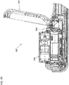
- Figure 39 is a sectional view through label printer 802.
- a cassette 700 of the type discussed with respect to Figures 32 to 37 is partially installed.
- the cassette is yet to make contact with the locking element 826, and therefore the locking element 826 is in its rest position i.e. partially protruding into the cassette receiving bay 808.
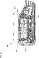
- Figure 41 shows the cassette 700 fully inserted in label printer 802, and the lid 850 has been closed.
- the locking elements 826 and 832 have passed over the top of locking portions 725 and 711 of the cassette, and accordingly the locking elements 826 and 832 have sprung back towards their rest position, with a portion projecting into the cassette receiving bay 808.
- the locking element 826 (and conductive portions thereof) are in contact with the conductive bar 728 of locking portion 725 such that the correct insertion of the cassette can be detected.
- the locking portion 832 can detect the insertion of the cassette by connecting to conductive bar 776 of locking portion 711.
- the lid 850 comprises projections 860 and 862 which respectively engage locking elements 826 and 832, so as to secure the locking elements against the cassette locking portions when the cassette is fully inserted and the lid 850 is closed.
- the locking element(s) of the label printer have ramped surfaces for causing deflection thereof when a cassette is inserted in the label printer.
- a surface of the cassette may be ramped or ribbed to cause deflection of the locking elements of the label printer as the cassette is received in the cassette receiving bay.
- the locking element(s) of the label printer may not necessarily comprise correspondingly ramped surfaces.
- both the cassette and locking element(s) of the label printer have correspondingly ramped surfaces.
- some embodiments may provide improved cassette locking and detection.
- a conductive member for cassette detection on a locking portion of the cassette then correct cassette insertion and locking can be detected.
- the particular structure of the cassette locking portion, such as the conductive bar in some embodiments not only acts as cassette detection means but the conductive member itself may also provide a locking function.
- a suitably designed locking element of a tape printing apparatus may "hook" itself over a corresponding conductive bar or other locking portion on the cassette such that the cassette can be securely held.
- Some embodiments may also provide an improved method of manufacturing a cassette comprising a cassette detection feature.
- the conductive bar 428 can be attached to the cassette 400 as a step in the production of the cassette.
- the conductive bar 428 can be attached to the cassette 400 manually, or it may be affixed to the cassette as part of an automated process of cassette manufacture.
- the conductive bar 428 can be affixed to the cassette 400 at any suitable stage in the cassette manufacturing procedure. For example it may be affixed before the base 402, top 404, and sides 406, 408, 410 and 412 are attached to each other. Alternatively the conductive bar 428 may be affixed to an otherwise completed cassette 400.
- the design of the receiving portions 430 and 432 which provide a push-fit for the conductive bar 428 facilitate the method of manufacture, since they enable the conductive bar 428 to be quickly and easily attached to the cassette 400. Any other type of friction fit is also possible between the conductive bar 428 and the seat or receiving portions 430 and 432, such as a snap-fit.
- the conductive bar 428 can be affixed to the cassette by an automated process, for example using a robotic arm which is configured to insert the conductive bar 428 in to the receiving portions 430 and 432.
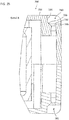
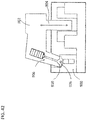
- Figure 42 is a schematic diagram demonstrating the insertion of a conductive bar 926 to a cassette 900.
- a machine 902 is configured for inserting the conductive bar in to the cassette 900.
- the machine 902 can move vertically as shown by arrow 904.
- the machine can also move in a direction into and out of the paper. In some embodiments the machine can also move in a direction from left to right with respect to Figure 42 .
- the machine 902 comprises an arm portion 906.
- the machine may hold a supply of conductive bars, for example in a hopper, or it may collect a conductive bar from a supply and then insert the conductive bar into the cassette 900.
- the machine 902 may hold the conductive bar 926 in any known way e.g.
- the machine 902 can insert the conductive bar 926 into the cassette by pushing it into the cassette e.g. by vertical movement in the direction of arrow 904, or it could push the conductive bar into the cassette in other ways e.g. with air pressure.
- the arm 906 of the machine is required to come into close proximity with the cassette in order to insert the conductive bar 926. Accordingly a space 910 is provided on the cassette, adjacent the receiving portion of the conductive bar, which gives the arm 906 room to move while inserting the conductive bar 926.
- Figure 35 for example, where the back wall 784 is shown spaced from the region where the conductive bar 776 is housed.
- Figures 43 to 45 show a locking element of a label printer configured to engage a label cassette, according to another embodiment.
- the locking element is shown generally at 1026 in Figure 43 .
- a conductive track 1028 is shown separately from the locking element 1026.
- the conductive track 1028 is configured to be attached to the locking element 1026, such that the conductive track 1028 can engage with a corresponding conductive member on a cassette to detect correct insertion thereof in the label printer.
- the locking element 1026 comprises a connecting portion 1027 for connecting the locking element to a cassette receiving bay of a label printer.
- the locking element 1026 also comprises a ramp portion 1032 which protrudes outwardly from the main body of locking element 1026.
- the conductive track 1028 generally comprises a first end 1036 and a second end 1038. In this embodiment the second end 1038 comprises a terminal of the conductive track.
- the first end 1036 comprises two tracks 1050 and 1052, configured to be respectively inserted through slots 1054 and 1056 of the locking element 1026.
- the first end 1036 of conductive track 1028 is shaped such that it can be manipulated to follow the contours of ramp portion 1032 of the locking element 1026.
- Figure 44 shows the conductive track 1028 partly attached to the locking element 1026.
- the second end 1038 of the conductive track is pushed in the direction of arrow A such that the conductive track 1038 lies against the rear side of the locking element 1026.
- the first end 1036 of the conductive track 1028 can also be manipulated such that it follows the contours of ramp portion 1032 of the locking element 1026.
- a first side 1060 may be considered a "front" side of the locking element 1026 and faces inwardly of a cassette receiving bay of a label printer.
- a second or “reverse” side 1062 of the locking element 1026 opposes the first side 1060 and faces outwardly of a cassette receiving bay of a label printer when inserted therein.
- Figure 45 is a view of the front side 1060 of the locking element 1026 when the conductive track 1028 has been attached thereto. It can be appreciated from this Figure that the conductive tracks 1050 and 1052 of the front end 1036 of the conductive track 1028 have been bent over to follow the contours of the ramp portion 1032 of the locking element 1026. The terminal end 1038 of the conductive track 1028 is visible through a slot 1070 in the locking element 1026.
Landscapes
- Printers Characterized By Their Purpose (AREA)
- Impression-Transfer Materials And Handling Thereof (AREA)
- Handling Of Continuous Sheets Of Paper (AREA)
- Details Of Rigid Or Semi-Rigid Containers (AREA)
- Electronic Switches (AREA)
- Replacement Of Web Rolls (AREA)
Description
- The present application relates to a label printer, and particularly to a label printer with cassette detection means and to a cassette for use in a label printer.
- Label printers are known, which use a supply of tape, housed in a cassette, received in the label printer. The tape comprises an image receiving layer and a backing layer which are secured to one another via an adhesive layer. Such label printers include a cutting mechanism for cutting off a portion of the tape after an image has been printed onto the image-receiving layer so that the portion of tape having the image can be used as a label. After the tape has been cut, the cut portion of the tape is pulled from the printer through a slit in the printer housing. The backing layer can then be removed allowing the image-receiving layer to be secured to an object using the adhesive layer.
- Known label printers comprise a cassette-receiving bay in which a cassette is received for printing. A printhead is provided in the cassette-receiving bay for co-operating with the supply of tape to print thereon. A platen may also be provided in the cassette-receiving bay positioned at a side of the tape opposite to the printhead when the cassette is received in the cassette-receiving bay. During printing, the printhead co-operates with the platen, with the tape passing therebetween for printing thereon. The platen may be driven by a motor for propagating the tape during printing. Alternatively, the platen may be freely rotatable and an additional drive roller may be provided for driving the tape during printing.
- In an alternative arrangement to that described above, a platen may be provided within the cassette. In such an arrangement, the tape cooperates with a surface of the platen. When received in the cassette-receiving bay the platen in the cassette co-operates with a drive mechanism in the cassette-receiving bay for driving the tape during printing. Alternatively, the platen is freely rotatable and an additional drive roller may be provided for driving the tape. During printing, the printhead in the cassette-receiving bay co-operates with the platen in the cassette with tape passing therebetween for printing thereon.
- In one arrangement, the printhead is moveable between a non-printing position and a printing position. In an alternative arrangement, the platen is moveable between a non-printing position and a printing position. In yet another arrangement, both the platen and printhead are movable so as to have non-printing and printing positions.
- The tape may be of a direct thermal type on which printing is achieved by direct application of heat from printing elements on the printhead. Alternatively, an ink ribbon may be provided, whereby ink is transferred from the ribbon to an image receiving tape by application of heat to the ink ribbon via printing elements on the printhead. The cassette may include a roll of die cut labels rather than a continuous tape.
- A problem exists in all the above-described arrangements, in that for good quality printing the tape and/or ink ribbon must be correctly aligned with the printhead during printing. Furthermore, the tape must remain correctly aligned with the printhead while printing occurs and must smoothly pass the printhead so as to ensure good quality printing. In order to ensure that this is the case, it is advantageous to prevent the cassette from moving during printing and cutting. Furthermore, the position of the cassette within the cassette-receiving bay should be predefined and readily reproducible whenever a cassette is inserted in the cassette-receiving bay.
- The problem is exacerbated in hand held printers which may be moved around during printing. In such an apparatus, it is even more important that the cassette is locked in a fixed position during printing.
-
WO 2006/013466 (DYMO) discloses a cassette locking and ejecting arrangement for a label printer apparatus. A label printer comprising a cassette-receiving bay in which a tape cassette is inserted, is provided. The cassette receiving bay is provided with a plurality of spring-loaded ejecting members for ejecting a cassette from the cassette-receiving bay. When a cassette is inserted in the cassette receiving bay, a pair of locking members hold the cassette in place against the biasing force exerted by the ejecting members. To eject the cassette, the locking members are disengaged from the cassette allowing the cassette to be pushed out of the cassette-receiving bay by the force exerted by the ejecting members. - There is a problem with the above-described arrangement, that when a cassette is inserted into the cassette receiving bay by a user, it is possible that the cassette will not properly engage with all of the locking members. This may occur, for example, if a user presses on only one edge of the cassette during insertion. If a cassette is engaged with one, but not all, of the locking members, then although the cassette may be retained within the cassette receiving bay against the biasing force of the ejecting members, the cassette may not be aligned properly with respect to the platen and print head for printing.
-
WO 2006/013466 (DYMO) has a pair of locking members which are biased, by means of a spring, towards a locking position so as to lock a cassette inserted into the cassette receiving bay in place. However, in the event that the label printer apparatus is subjected to a sudden impact, i.e. if it is dropped by a user, it is possible that the locking members will be moved against the biasing force of the spring so as to release the cassette. Accordingly, when a user subsequently resumes printing with the label printer apparatus, the cassette will not be properly locked in the cassette receiving bay in the correct position for printing, and printing will be adversely effected or impossible. - Furthermore, in the case that a cassette inserted into a cassette receiving bay is not properly engaged by one or more of a plurality of locking members, it may not be apparent to a user, which locking members are not engaged properly with the cassette and what action is required in order to rectify the problem.
-
US 2011/103871 discloses a label printer cassette having at least one locking portion for engaging with a co-operating locking element of a tape printer when the cassette is correctly inserted in the printer. The locking portion comprises a conductive area. - In a first aspect there is provided a cassette as set forth in
claim 1. - In another aspect there is provided a method of manufacturing a cassette as set forth in
claim 14. - Features according to some embodiments are set forth in the dependent claims.
- For a better understanding of some embodiments and to show how the same may be carried into effect, embodiments will now be described by way of example only with reference to the accompanying drawings, in which:
-
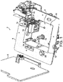
Figure 1 is a top perspective view of an embodiment of a label printer, the label printer having its lid open and no cassette present; -
Figure 2 is another top perspective view of the label printer shown inFigure 1 ; -
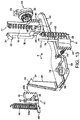
Figure 3 is a view illustrating the position of a first locking element of the label printer shown inFigure 1 ; -
Figure 4 is a view illustrating the position of a first ejector element of the label printer shown inFigure 1 -
Figure 5 is a view illustrating the position of a second locking element of the label printer ofFigure 2 ; -
Figure 6 is a view illustrating the position of a second ejector element of the label printer shown inFigure 2 ; -
Figure 7 is a top perspective view of the label printer ofFigure 1 illustrating the positions of a first locking element and a first ejector element with a cassette installed in the cassette-receiving bay (the cassette is not shown for clarity); - Preferably said cassette comprises a ledge portion projecting from a side of said cassette, said ledge portion comprising said conductive bar.
- Preferably said cassette comprises a recess in said side, wherein said ledge portion is located in said recess.
- Preferably said cassette comprises a second conductive bar.
- Preferably said second conductive bar is located on a side of said cassette opposite from said conductive bar.
- Preferably said cassette comprises a base, a top, and at least one side extending between said base and said top, wherein said conductive bar is comprised on said at least one side.
- Preferably said bar comprises a metal.
- Preferably said bar is cylindrical in cross section.
- Preferably a main body portion of said cassette comprises a plastic material.
- Preferably said supply roll comprises at least one of a supply of image receiving tape and a supply of ink ribbon.
- In another aspect there is provided a label printing apparatus comprising: a cassette receiving bay adapted to receive a cassette, said cassette receiving bay having a base, an opening opposite the base, and side walls extending between the base and the opening; a cassette locking mechanism comprising at least one locking element having a locking position for engagement with a cassette inserted into said cassette receiving bay; and cassette detection means operable to determine whether said at least one locking element is engaged with a cassette inserted into the cassette receiving bay; wherein the cassette detection means comprises at least one conductive surface disposed on the at least one locking element; wherein the locking element comprises a first surface for engaging a surface of a cassette as the cassette is inserted into the cassette receiving bay so as to cause deflection of said locking element, and a second surface arranged to contact a conductive portion of the cassette for retaining the cassette when it is correctly inserted in the cassette receiving bay.
- Preferably said first and second surfaces of said locking element are ramped.
- Preferably said first and second ramped surfaces converge towards a connecting portion connecting said first and second ramped surfaces.
- Preferably said locking element is configured to be deflected by engagement of said locking element with a ramped or ribbed surface of said cassette, as said cassette is inserted in said label printing apparatus.
- Preferably said locking element comprises at least one shoulder portion adjacent said first ramped portion.
- Preferably said conductive surface extends over said second ramped surface, said shoulder portion and over a rear side of said locking element towards a terminal of said conductive surface.
- Preferably said conductive surface comprises a concavely curved portion adjacent said second ramped surface.
- In another aspect there is provided a method of manufacturing a cassette for a label printing apparatus, said method comprising: providing a cassette main body having a base, a top, and sides extending between said base and said top; and inserting a conductive bar into a receiving portion of said cassette, such that said conductive bar extends along said cassette in a direction perpendicular to a rotational axis of a supply roll housed in said cassette.
- Preferably said conductive bar is manually inserted into said receiving portion.
- Preferably said conductive bar is inserted into said receiving portion as part of an automated process.
- Preferably said conductive bar is a friction fit in said receiving portion.
- Preferably said friction fit comprises one of a push-fit and a snap-fit.
- For a better understanding of some embodiments and to show how the same may be carried into effect, embodiments will now be described by way of example only with reference to the accompanying drawings, in which:
-
Figure 1 is a top perspective view of an embodiment of a label printer, the label printer having its lid open and no cassette present; -
Figure 2 is another top perspective view of the label printer shown inFigure 1 ; -
Figure 3 is a view illustrating the position of a first locking element of the label printer shown inFigure 1 ; -
Figure 4 is a view illustrating the position of a first ejector element of the label printer shown inFigure 1 -
Figure 5 is a view illustrating the position of a second locking element of the label printer ofFigure 2 ; -
Figure 6 is a view illustrating the position of a second ejector element of the label printer shown inFigure 2 ; -
Figure 7 is a top perspective view of the label printer ofFigure 1 illustrating the positions of a first locking element and a first ejector element with a cassette installed in the cassette-receiving bay (the cassette is not shown for clarity); -
Figure 8 is another top perspective view of the label printer shown inFigure 7 ; -
Figure 9 is a view illustrating the position of the first locking element shown inFigure 3 during insertion/ejection of a cassette; -
Figure 10 is a view illustrating the position of the first ejector element shownFigure 4 during insertion/ejection of a cassette; -
Figure 11 is a view illustrating the positions of the second locking element and the second ejector element shown inFigure 5 during insertion/ejection of a cassette; -
Figure 12 is a view illustrating the position of the third ejector element shown inFigure 6 during insertion/ejection of a cassette; -
Figure 13 is a view of the ejector mechanisms and the locking mechanism of the label printer ofFigure 1 ; -
Figure 14 is a side perspective view of the right hand side of the label printer ofFigure 1 , showing an ejector mechanism; -
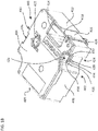
Figure 15 is a bottom perspective view of the label printer ofFigure 1 ; -
Figure 16 is a side perspective view of the left hand side of the label printer ofFigure 1 , showing a print head stop mechanism, when the lid of the label printer is open and no cassette is inserted; -
Figure 17 is an enlarged view of the first locking element shown inFigure 3 , showing cassette detection means according to a first embodiment; -
Figure 18 is a view of a cassette according to an embodiment; -
Figure 19 is an alternative view of the cassette ofFigure 18 ; -
Figures 20 and21 are cross sections of side views of the cassette ofFigures 18 and19 ; -
Figure 21A is an isometric view of a portion of a cassette according to an embodiment; -
Figure 22 is a schematic representation of a cassette inserted in a cassette receiving bay where: (i) the first and second locking elements are properly engaged with the cassette; and (ii) the first locking element is properly engaged with the cassette and the second is not engaged with the cassette; -
Figure 23 is an enlarged view of the first locking element shown inFigure 3 , showing cassette detection means according to an alternative embodiment; -
Figure 24 is a view of a cassette according to a further embodiment; -
Figure 25 is a detailed view of a portion of the cassette ofFigure 24 ; -
Figure 26 is a sectional view of a portion of the cassette ofFigure 25 ; -
Figures 27 to 29 are each views of a locking element of a label printer according to an embodiment; -
Figure 30 is a sectional view showing a locking element of a label printing apparatus engaging with a cassette; -
Figure 31 is a sectional view showing a locking element of a label printing apparatus engaging with a cassette, when a lid of the label printing apparatus is closed. -
Figure 32 is a perspective view of a cassette according to a further embodiment; -
Figure 33 is a plan view of the cassette ofFigure 32 ; -
Figures 33A to 33D are sectional views of the cassette ofFigure 32 ; -
Figures 34 to 37 are detailed views ofFigures 33A to 33D respectively; -
Figure 38 is a perspective view of a label printer according to a further embodiment; -
Figure 39 is a sectional view of the label printer ofFigure 39 , further including a cassette; -
Figure 40 shows the label printer ofFigure 39 , with the cassette partially inserted; -
Figure 41 shows the label printer ofFigure 9 , with the cassette fully inserted; -
Figure 42 is a schematic diagram of a machine for manufacturing embodiments of the cassette disclosed herein. -
Figures 43 to 45 are each views of a locking element of a label printer according to another embodiment - Referring to
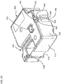
Figure 1 , the label printer 2 comprises a body 4, a lid (or cover) 6 and a cassette-receiving bay 8. The cassette-receiving bay 8 has an opening in a top portion of the body for vertical insertion of a cassette. Alternatively the opening could be on another side of the label printer 2. Thelid 6 is hinged for closing over the top opening. In an alternative embodiment, the lid (or cover), may be a detachable lid which is completely detachable from the body 4 of the label printer 2 when in an open position. - The cassette-receiving bay 8 comprises a recess forming an opening for receiving a cassette. The recess is formed by a
base 10 andsides 12 extending from the base 10 to the top opening. Aplaten 14 and aprinthead 16 are provided in the cassette-receiving bay 8. Theprinthead 16 is movable towards theplaten 14 whereby, during printing, theprinthead 16 co-operates with theplaten 14, with tape passing therebetween for printing thereon. Theplaten 16 is driven by a motor (not shown) for propagating the tape during printing. An ink ribbon take-upsprocket 18 extends from thebase 10 of the cassette-receiving bay 8 for cooperating with an ink ribbon take-up spool of a cassette when inserted into the cassette-receiving bay 8. Thesprocket 18 is driven by a motor (not shown) for winding the ink ribbon around the ink ribbon take-up spool during printing. Aslit 19 is provided in the body 4 of the label printer forming an exit through which the tape passes after printing. Acutting mechanism 21 is provided adjacent the exit slit 19 for cutting off the printed portion of tape to provide a printed label. - A
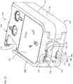
first ejector element 24 is visible on a side-wall of the cassette-receiving bay 8. Also visible inFigure 1 is a lockingelement 26 of a locking mechanism (which is not visible) on the left hand side of the cassette-receiving bay 8. The lockingelement 26 is described in more detail below. Anactuator button 29 is provided on the surface of the body 4 for actuating the locking mechanism. - Referring to
Figure 2 , asecond ejector element 28 of a second ejector mechanism (which is not visible) is shown on the opposite side wall of the cassette receiving bay 8 to thefirst ejector element 24. Athird ejector element 30 of a third ejector mechanism (which is not visible) is positioned on the right hand side of the cassette receiving bay 8. Asecond locking element 32 of the locking mechanism (which is not visible) is positioned on the right hand side of the cassette-receiving bay 8. - Referring to
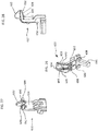
Figures 3, 4 ,5 and 6 , each of the locking andejector elements - Each locking
element projection 34 and anelongate element 36 extending in a direction from the base 10 towards the top opening of the cassette-receiving bay 8. Theprojection 34 is at a top end of theelongate element 36 and extends towards a central portion of the cassette-receiving bay 8 through a corresponding opening in theside wall 12 of the cassette-receiving bay 8. Eachprojection 34 has a sloped upper surface for cooperating with a cassette inserted into the cassette-receiving bay 8 for moving the locking element from a locking position to an unlocked position. One of the side walls of the cassette-receiving bay 8 has aportion 39 projecting into the cassette-receiving bay 8 forming a guide for a corresponding recess in a cassette when inserted into the cassette-receiving bay 8. The lockingelement 32 is positioned in an opening in theguide 39 and extends therefrom into the cassette-receiving bay 8 thereby forming a combined guiding and locking arrangement. The lockingelements Figure 1 ,2 ,3 and5 show one example of the structure of a locking element, and it should be appreciated that the locking element can take the form of other configurations (see for exampleFigures 27 to 29 ). - Each ejecting
element ejector elements elongate element 38 extending in a perpendicular direction relative to the side wall through an opening in the side wall. - Referring to
Figures 7 and8 , when a cassette is installed in the cassette-receiving bay 8, the first, second and thirdejector elements base 10 and the first andsecond locking elements -
Figures 9, 10 ,11 and 12 illustrate the positions of the locking andejector elements Figures 9, 10 ,11 and 12 the cassette is not shown for clarity. - During insertion, the cassette contacts the locking and
ejector elements projections 34 of the lockingelements elements side walls 12. The lockingelements elements Figures 7 and8 . The lockingelements ejectors - To eject a cassette, the
ejector button 29 is actuated by a user pressing down on it, which unlocks the mechanism by moving the lockingelements side walls 12 of the cassette-receiving bay 8. The cassette is thus released and theejectors - Referring to
Figure 13 , the locking mechanism and the ejector mechanisms will now be described in more detail. Theejectors 41 each comprise abody portion 40. Adjacent to afirst edge 40a thereof, thebody portion 40 hashole 42 formed therethrough, the axis of the hole arranged so as to be parallel to thefirst edge 40a of thebody portion 40. Thehole 42 has a circular cross-section. Along asecond edge 40b of thebody portion 40, opposite thefirst edge 40a, thebody portion 40 comprises arack portion 44. Anejector element 46 extends perpendicularly from the plane of thebody portion 40, which extends between the first andsecond edges first edge 40a of thebody portion 40, i.e. adjacent to thehole 42. Theejector element 46 is arranged so as to extend through a slit (not shown) in theside wall 12 of the cassette-receiving bay 8. Eachejector 41 further comprises a biasingmember 48 at the bottom end of thefirst edge 40a of thebody portion 40. The biasingmember 48 extends in the plane of thebody portion 40 perpendicular to the axis of thehole 42. The biasingmember 48 is coupled to one end of anexpansion spring 50, for biasing theejector element 46 towards the top end of the corresponding slit (not shown) in theside wall 12 of the cassette-receiving bay 8. The top end of the slit in theside wall 12 is the end adjacent to the top opening of the cassette receiving bay 8, with the bottom end of the slit being that which is adjacent to thebase 10 of the cassette receiving bay 8. - The
body portion 40 of theejector mechanism 41 is mounted on ashaft 52, which extends through thehole 42 in thebody portion 40. Adamper 54 is disposed adjacent to therack portion 44 of thebody portion 40. Thedamper 54 comprises a pinion (or gear) 56 which is rotatably mounted to adamper mount part 58. -
Figure 14 shows anejector mechanism 41 of the label printer 2. As can be seen fromFigure 14 , theejector mechanism 41 comprises anejector housing 60. Theejector housing 60 is approximately cylindrical in shape. Theshaft 52 of theejector mechanism 41 is disposed so as to be co-axial with theejector housing 60. Accordingly, thebody portion 40 is slidably mounted within theejector housing 60, by means of theshaft 52 passing through thehole 42 formed at thefirst end 40a of thebody portion 40. Theejector housing 60 comprises a first elongate opening along its length (not shown). The first elongate opening of theejector housing 60 is aligned with a corresponding slit formed in aside wall 12 of the cassette receiving bay 8. Theejector element 46 of theejector mechanism 41 protrudes into the cassette-receiving bay 8 through the first elongate opening and through the slit in theside wall 12, so as to interact with a cassette. Theejector housing 60 further comprises a second elongate opening (not shown) through which the biasingmember 48 of thebody portion 40 extends. As can be seen inFigure 14 , the biasingmember 48 is attached to the lower end of thespring 50, i.e. the end of thespring 50 closest to thebase 10 of the cassette receiving bay 8. Theejector housing 60 comprises a fixedextension 62 disposed at an upper end of thehousing 60, adjacent to the top of the second elongate opening. The upper end of thespring 50 is attached to the fixedextension 62. Accordingly thespring 50 acts so as to bias thebody portion 40 of theejector mechanism 41 towards the upper end of thehousing 60. Theejector housing 60 further comprises a third elongate opening (not shown), through which therack portion 44 at thesecond edge 40b of thebody portion 40 extends. The third elongate opening is aligned relative to adamper 54, such that therack portion 44 meshes with thepinion 56 of thedamper 54. - Referring to
Figures 13 and15 , the locking mechanism will now be described in more detail. The locking mechanism comprises the two lockingelements elements elongate element 36 and aprojection 34. Eachprojection 34 has a sloped upper surface for cooperating with a cassette inserted into the cassette-receiving bay 8 for moving the lockingelements elements actuating bar 64. Each of the lockingelements actuating bar 64 by arespective coupling member elements rotation actuating bar 64 to each other. The centres ofrotation return spring 74 is provided for biasing the lockingelements bar 64 has a centre ofrotation 76, which also comprises a pivot point attached to the printer body 4. Thefirst locking element 26 is rotatably coupled to theactuating bar 64 by means of aslot 78, provided in the distal end of thecoupling member 66 relative to thefirst locking element 26, which cooperates with apin 80 provided at afirst end 65 of theactuating bar 64. Thesecond locking element 32 is similarly rotatably coupled to a second end of theactuating bar 64. - Referring to
Figure 16 , theejector button 29 is disposed adjacent to the cassette-receiving bay 8, so as to be pressed by a user to eject a cassette from the cassette-receiving bay 8 when thelid 6 is open and a cassette is inserted. Theejector button 29 comprises anactuator part 82. The upper end of the actuator part (not shown) has a circular cross-section and extends through an opening in the upper surface of the label printer 2, such that it can be pressed by a user. The lower end of theactuator part 82 comprises first and secondtubular portions flange part 85 disposed therebetween. Theflange part 85 of the ejector button actuator part is angled at the lower end thereof, at an angle of approximately 45°. First and secondbutton guide shafts tubular portions actuator part 82, respectively, so as to guide the motion of theactuator part 82 when pressed by a user. First and second eject button springs 88, 89 are disposed on the first andsecond guide shafts actuator part 82 towards the top of the label printer 2. - Referring to
Figure 17 , thefirst locking element 26 comprises cassette detection. In this embodiment the cassette detection comprises first andsecond contact pads cassette detection circuitry 310 by means of respective first and second conduction connections such as wires, conductive pads, conductive material, etc. 306, 308. These conduction connections will be referred to as wires in the following but as will be appreciated this is by way of example only and the wires can be replaced by any other suitable conduction arrangement. The first andsecond contact pads projection 34 of thefirst locking element 26. Thefirst wire 306 is connected to thefirst contact pad 302 at one end and extends from thefirst contact pad 302 along the surface of theelongate element 36 and is connected at the other end to thecassette detection circuitry 310. Similarly, thesecond wire 308 connects thesecond contact pad 304 to thecassette detection circuitry 310. In the current embodiment, thesecond locking element 32 is similarly provided with first andsecond contact pads cassette detection circuitry 310 via first andsecond wires Figures 27 to 29 . - An example of a cassette according to an embodiment is shown in
Figure 18 . Thecassette 400 comprises abase 402, a top 404, andsides cassette 400 also comprises arecess 414 for accepting a print head when thecassette 400 is inserted in a label printer. - The
cassette 400 also carries a supply ofimage receiving tape 416 andink ribbon 418. After printing the image receiving tape passes out of the cassette viaoutlet 420 and the ink ribbon is taken up in thecassette 400 on ink ribbon take upspool 422. -
Side 406 of the cassette comprises arecess 424. Therecess 424 comprises a locking portion shown generally at 425. The lockingportion 425 comprises aledge portion 426 upon which is mounted an elongateconductive bar 428. Theconductive bar 428 may be cylindrical or of any other cross-section such as square, rectangular, hexagonal etc. Theconductive bar 428 is retained in seat portions, or receiving portions, 430 and 432 at either side ofledge 426. In the region between theseats conductive bar 428 is spaced from the surfaces of thecassette 400 and theledge 426. That is theconductive bar 428 spans atrough portion 434 ofledge 426. - A
recess portion 436 ofcassette 400 is more clearly shown inFigure 19 . - Similarly to the
recess 424 described with respect toFigure 18 ,recess 436 also comprises a locking portion shown generally at 437 comprising aledge portion 438.Ledge portion 438 supports a second elongateconductive bar 440 which is retained at either end in seats, or receiving portions, 442 and 444 ofledge 438. Theconductive bar 440 may be of any cross sectional shape such as cylindrical, square, rectangular, hexagonal etc. Theconductive bar 440 spans atrough portion 446 ofledge 438. -
Figures 20 and21 are sectional views of thecassette 400. -
Figure 20 shows the positioning of theconductive bar 428 on theledge 426. WhilstFigure 20 shows the top surface of thebar 428 flush with the upper edge of the ledge 426 (i.e. inseats 432 and 430), it should be appreciated that in alternative embodiments the ends of theconductive bar 428 may sit proud of or be recessed in theseats -
Figure 21 shows the positioning of theconductive bar 440 in theledge 438. Again it should be appreciated that although the ends of theconductive bar 440 are shown as flush with theseats ledge 438, in alternative embodiments theconductive bar 440 may sit proud of or be recessed in theseats -
Figure 21A shows a further embodiment of a cassette 400'. Conductive bar 428' is located on a ledge portion 426'. More particularly the conductive bar 428' is located between receiving portions 430' and 432'. The conductive bar 428' may be a friction fit with the receiving portions 430' and 432', such as a push-fit or a snap-fit. Alternatively the conductive bar 428' may be attached to the receiving portions 430' and 432' with an adhesive, such as glue. Alternatively the conductive bar 428' can be in-moulded during an injection moulding process. Cassette 400' also comprises rib 427' which protrudes from the upper surface of ledge 426'. The rib 427' is positioned proximate to conductive bar 428'. The rib 427' has a longitudinal axis which extends laterally of, and parallel to, longitudinal axis of conductive bar 428'. The rib 427' may be of any cross-sectional shape such as square, circular, semicircular etc. The rib 427' may act as a guide to help ensure that the conductive bar 428' is correctly located between receiving portions 430' and 432' when inserted. The rib 427' also acts as a wall to stop the conductive bar 428' from springing out of the receiving portions 430' and 432'. The rib 427' also prevents the conductive bar 428' from being removed easily from the cassette, and therefore may prevent inadvertent removal of the conductive bar 428'. In some embodiments the rib 427' is slightly spaced from the conductive bar 428'. In another embodiment the rib 427' engages the conductive bar 428'. In such an embodiment the conductive bar 428' is frictionally engaged with receiving portions 430' and 432' and rib 427', once correctly inserted. It can also be appreciated from this Figure that the conductive bar 428' is spaced from a sidewall of cassette 400' by a distance Z. It should be appreciated that Z can be of any distance, including zero (in which case the conductive bar 428' will also be in contact with the sidewall of the cassette). - The operation of the above described locking mechanism, ejector mechanisms and cassette detection means will now be described. When there is no cassette inserted in the cassette-receiving bay 8, the
spring 50 of eachejector mechanism 41 is in an unextended state and, accordingly, eachejector element side wall 12 of the cassette-receiving bay 8. The lockingelements return spring 74 acting on theactuating bar 64. - When a cassette is inserted into the cassette receiving bay 8, the base of the cassette presses down on each
ejector element body portion 40 of each ejector to move downwards along theshaft 52 and causes thespring 50 to extend. As thebody portion 40 moves downwards, therack portion 44 is meshed with thepinion 56 of thedamper 54. Accordingly, thepinion 56 of thedamper 54 is rotated as the cassette is inserted and provides a resistance to the force applied to the cassette by a user who inserts the cassette into the cassette receiving bay 8. The resistance provided by thepinion 56 engaging with therack portion 44 is preferably selected so as not to be so great that a user requires excessive force to insert a cassette into the cassette-receiving bay 8, which could damage components of the ejector mechanisms. - When the cassette has been inserted fully into the cassette-receiving bay, the locking
elements ejector elements projection 34 of thefirst locking element 26 engages withconductive bar 428 of thecassette 400. Accordingly, the first andsecond contact pads first locking element 26 are in contact with theconductive bar 428. Theconductive bar 428 is dimensioned such that a conductive connection between the first and the second pad is created when the locking element engages theconductive bar 428. Similarly, theprojection 34 of thesecond locking element 32 engages withconductive bar 440. Accordingly, the first andsecond contact pads second locking element 32 are in contact with theconductive bar 440 of thecassette 400. Theconductive bar 440 is dimensioned such that a conductive connection is created between the first and the second pad when the locking element engages the locking member. - The
cassette detection circuitry 310 may detect the engagement of the first andsecond locking elements conductive bars second contact pads element second contact pads conductive bars second locking elements - Referring to
Figure 22(i) , when the cassette is correctly inserted and both the first andsecond locking elements Figure 22(ii) , it is possible that one of the locking elements will not be properly engaged with the cassette if, for example, the cassette is inserted with an uneven force. In this case, no current will flow between the first andsecond contact pads second locking element 32 because the first andsecond contact pads 303, 304 are not in contact with theconductive bar 440 ofcassette 400. The cassette detection circuitry will determine that thesecond locking element 32 is not engaged properly with the cassette. - When it is determined by the cassette detection circuitry that one or more of the locking
elements more locking element Figure 22(ii) on the display means, to indicate which side of the cassette must be pressed in order for the cassette to be inserted properly. Such an indication may also be displayed in the event that one or more of the locking elements disengages from the cassette, for example, as a result of the printer being dropped and subjected to a sudden impact. The latter may also be displayed in the event that one or more of the locking elements disengages from the cassette during transport of the label printer with a cassette installed. - Once the cassette has been inserted correctly, the cassette detection circuitry detects the engagement of the locking
elements - After printing, a cassette may be ejected by a user pressing the
eject button 29. When theeject button 29 is pressed, the downward movement of theactuating part 82 causes theangled flange part 85 to push against thefirst end 65 of theactuating bar 64. Referring again toFigure 15 , the actuatingbar 82 rotates around its centre ofrotation 76 in an anti-clockwise direction (as viewed). Accordingly, thecoupling member 66 of thefirst locking element 26 rotates clockwise around centre ofrotation 70, thereby moving thefirst locking element 26 to the unlock position. At the same time, thecoupling member 68 of thesecond locking element 32 rotates anti-clockwise around centre ofrotation 72, thereby moving thesecond locking element 32 to the unlock position. - With the locking
elements ejector elements ejector mechanisms 41 contract, theejector elements side walls 12 of the cassette-receiving bay 8 and push the cassette out of the cassette receiving bay 8. At the same time, therack portion 44 of eachejection mechanism 41 is meshed with thepinion 56 of the correspondingdamper 54. Accordingly, the engagement of therack portion 44 and thepinion 56 provides a resistance to the upward movement of theejector elements damper 54, the acceleration of an ejector element in the upward direction under the force of theexpansion spring 50 is reduced. The cassette is thus gradually ejected from the cassette-receiving bay 8. The degree of resistance provided by thepinion 56 of thedamper 54 may be determined by the viscosity of oil used to lubricate the pinion with respect to the damper mountpart 58. - In an alternative embodiment, only one of the locking elements may be provided with contact pads for detecting engagement of that particular locking element with the cassette. In this case the user may be informed of whether or not the locking element provided with the contact pads is properly engaged with the cassette. Preferably, the one locking element provided with contact pads is positioned adjacent the print head such that it is detected that the cassette is positioned correctly adjacent the position where the image is formed on the tape. In another embodiment, the label printer is only provided with a single locking element for retaining a cassette in the cassette receiving bay. In this case, the single locking element could be provided with contact pads for detecting the insertion of a cassette as described above. Preferably, the single locking element is positioned adjacent the print head.
- Referring to
Figure 23 , in yet another embodiment thefirst locking element 26 is provided with asingle contact pad 302 which is connected tocassette detection circuitry 310 byconductive connection 306, which can of course take any suitable format such as a wire or the like. Similarly, thesecond locking element 32 is provided with a single contact pad which is connected to thecassette detection circuitry 310 by means of a conductive connection such as awire 306 or the like. In this embodiment, the cassette may be provided with a conductive connection between the two conductive locking elements of the cassette. Correct insertion of the cassette will result in the completion of a circuit. - A cassette according to another embodiment is shown in
Figure 24 . Thecassette 500 comprises abase 502, top 504 and aside 506 connecting the base 502 to the top 504. A supply ofimage receiving tape 516 is contained within thecassette 500 and after printing exits the cassette viaoutlet 520. Thecassette 500 also comprises arecess 514 for accepting a print head when the cassette is inserted in a label printer. - The
cassette 500 also comprises a locking portion shown generally at 525, similar to the locking portion of the cassette shown inFigures 18 and19 . - The locking
portion 525 comprises a rib orledge 526 which extends aroundside 506 of thecassette 500.Seats ledge 526, and aconductive bar 528 is supported at either end by the seats, or receiving portions, 530 and 532. - The locking
portion 525 is shown in more detail inFigures 25 and 26 . - From
Figure 25 it can be seen how theconductive bar 528 is supported byseats portion 525 also comprises atrough portion 534 which is spanned by theconductive bar 528 between theseats conductive bar 528 maybe of any cross sectional shape. -
Figure 26 shows a cross section through thecassette 500. Between theseats 530 and 532 a lower edge of theconductive bar 528 rests in thetrough 534, with an upper portion of the conductive bar sitting proud of thetrough 534. In another embodiment the conductive bar may be spaced from the surfaces of thecassette 500 in the region between theseats -
Figure 32 shows a cassette according to a further embodiment. Thecassette 700 comprises abase 702, a top 704 andsides printhead recess 714. Certain features of the cassette are symmetrical about acentre line 715. For example a lockingportion 725 is symmetrical aboutcentre line 715. This allows thecassette 700 to be used in two types of cassette receiving bays, where those cassette receiving bays mirror each other. - The locking
portion 725 comprises a firstconductive bar 728 which is received at either end by seat portions or receivingportions conductive bar 728 is positioned above aledge portion 726, upon which is mountedelongate rib 727. - The locking
portion 725 also comprises a secondconductive bar 760 which is received at either end by seat portions or receivingportions elongate rib 766 which is positioned adjacentconductive bar 760. -
Figure 33 is a plan view of thecassette 700. Theconductive bar 728 is visible from this view. It can also be appreciated that afurther locking portion 711 comprising one or more conductive bars (similar to the side shown inFigure 32 ) is also present onside 710. -
Figure 33A is a sectional view ofcassette 700 through section X-X. In this figure the conductive bars are present in the cassette. SeeFigure 34 for detail A. -
Figure 33B is a sectional view ofcassette 700 through section X-X. In this figure the conductive bars are omitted. SeeFigure 35 for detail B. -
Figure 33C is a sectional view ofcassette 700 through section Y-Y. In this figure the conductive bars are present in the cassette. SeeFigure 36 for detail C. -
Figure 33D is a sectional view ofcassette 700 through section Y-Y. In this figure the conductive bars are omitted. SeeFigure 37 for detail D. -
Figure 34 shows detail A ofFigure 33 . Detail A shows a sectional view throughconductive bars portion 711.Conductive bar 776 is received in a receiving portion orseat portion 780, andconductive bar 778 is housed in receiving portion orseat portion 782. -
Figure 35 shows detail B. In this figure theconductive bars portion 780 tapers up to aback wall 784 which extends vertically to meet top 704 of the cassette. That is theback wall 784 joins to tapering wall 786 which tapers down to the region where theconductive bar 776 is housed (as shown inFigure 34 ). The receivingportion 780 also comprisesregion 788 which has aface 790 which also tapers to meet the region where theconductive bar 776 is housed. - These tapering walls facilitate insertion of the
conductive bar 776. The tapering surfaces 786 and 790 act as a guide to smoothly and correctly locate theconductive bar 776 as it is being inserted. Theback wall 784 being laterally spaced from where theconductive bar 776 is located also provides room for a user's hand or automated item of machinery when inserting the conductive bar 776 (this can be further appreciated fromFigure 42 ). - There is also some elasticity or flexibility in the materials forming the seats or receiving portions of the conductive bars. As such that the seats can spring apart slightly to allow insertion of the conductive bar, and then spring back again to their original position so as to securely hold the bar.
- It will be appreciated that receiving
portion 782 is similarly structured. This structure also applies to other regions of the cassette where conductive bars are located, forexample seat portions -
Figure 36 is a view of detail C fromFigure 33C . This Figure is through section Y-Y, approximately midway alongconductive bars ribs -
Figure 37 is also through section Y-Y, with theconductive bars ribs Figure 37 . These ribs act as per the rib 427' discussed inFigure 21A , and theribs Figure 32 . - Locking elements for locking a cassette in a label printer have been discussed earlier, for
example locking elements Figures 3 ,5 ,17 ,22 and23 etc. -
Figures 27 to 29 show an alternative embodiment of a locking element. The locking element is shown generally at 626 inFigure 27 . The lockingelement 626 comprisesconductive tracks element 626 also comprises aramp portion 632 which protrudes upwardly from the locking portion. Either side of the rampedportion 632 areshoulder portions conductive tracks element 626 also comprises amain body portion 634 in the form of an upstanding post. - As will be appreciated from
Figure 28 theconductive track 628 extends from a front side of thelocking element 626, along a rampedportion 629, across a top surface of the locking element overshoulder 642, and then down arear side 637 of thelocking element 626. Theconductive track 628 can therefore be considered to extend from afirst point 636 to a terminal 638 where it may connect with printer circuitry. Theconductive track 628 also comprises a concavelycurved portion 640 proximate to thefirst end 636. The concavely curved portion may assist with assembly. The conductive track 630 (not shown inFigure 28 ) extends in the same manner asconductive track 628. - The
reverse side 637 of thelocking element 626, and in particular the reverse side of theconductive tracks Figure 29 . Also clearly visible inFigure 29 isconnection portion 645 of lockingelement 626.Connection portion 645 slots into a corresponding aperture in a label printing apparatus so that the lockingelement 626 can be retained therein. - Also shown in
Figure 29 areprojections projections heat stake projections -
Figures 30 and31 show the interaction of a locking element 626' with a cassette 400' inserted therein. The cassette 400' comprises a conductive bar 428'. The locking element 626' comprises a conductive track 628' and 630' for interacting with conductive bar 428' of cassette 400', so as to detect when the cassette 400' is properly installed in the tape printing apparatus. The purpose of ramp portion 632' of locking element 626' can also be appreciated from this Figure. As the cassette 400' is inserted into the tape printing apparatus the ledge portion 426' acts on the ramp portion 632' of the locking element 626', thus forcing the locking element 626' to move in the direction of arrow X. After the cassette is inserted a certain distance and the ledge 426' and conductive bar 428' have moved under the most inwardly facing portion of locking element 626', then the locking element 626' springs back in the direction of arrow Y such that the conductive bar 428' (and consequently the cassette 400') is held in place by the locking element 626'. Also visible inFigures 30 and31 is lid 650'. The lid 650' comprises a projection or "door pal" 652' which projects into the cassette receiving bay of the tape printing apparatus. - The function of the projection 652' is best appreciated by viewing
Figure 31 . In this figure the cassette bay lid 650' is in the closed position and a bottom edge 654' of projection 652' has engaged with the top of locking element 626'. Accordingly movement of locking element 626' in the direction of arrow X is prohibited since it is blocked by projection 652'. This ensures that when the lid 650' is closed the locking element 626' remains engaged with the locking portion of the cassette. The cassette 400' is therefore securely held in the tape printing apparatus. This also ensures that the cassette is securely held in the event of the printer being dropped or subject to a large vibration. -
Figure 38 shows aportable label printer 802 according to another embodiment. Thelabel printer 802 comprises acassette receiving bay 808 comprising aprinthead 816. Thelabel printer 802 also comprises alocking element 826. The lockingelement 826 is configured to operate in the same or a similar manner to the locking elements described with respect toFigures 22 ,23 and27 to 29 . Thelabel printer 802 also comprises alid 850. -
Figure 39 is a sectional view throughlabel printer 802. In this figure acassette 700 of the type discussed with respect toFigures 32 to 37 is partially installed. The cassette is yet to make contact with the lockingelement 826, and therefore thelocking element 826 is in its rest position i.e. partially protruding into thecassette receiving bay 808. - In
Figure 40 the cassette has been further inserted. The lockingportion 725 of the cassette is in contact with the lockingelement 826, which is accordingly pushed back or deflected in to the body of the label printer and out of the cassette receiving bay. This has also occurred on the opposite side of the cassette, where the lockingportion 711 is in contact with lockingelement 832, thus pushinglocking element 832 out of the cassette receiving bay and into the label printer body. -
Figure 41 shows thecassette 700 fully inserted inlabel printer 802, and thelid 850 has been closed. In this figure the lockingelements portions elements cassette receiving bay 808. In a similar manner as described with respect toFigure 22 (i) andFigure 31 , the locking element 826 (and conductive portions thereof) are in contact with theconductive bar 728 of lockingportion 725 such that the correct insertion of the cassette can be detected. Similarly the lockingportion 832 can detect the insertion of the cassette by connecting toconductive bar 776 of lockingportion 711. It can also be seen fromFigure 41 that thelid 850 comprisesprojections elements lid 850 is closed. - Some embodiments have been described where the locking element(s) of the label printer have ramped surfaces for causing deflection thereof when a cassette is inserted in the label printer. In other embodiments a surface of the cassette may be ramped or ribbed to cause deflection of the locking elements of the label printer as the cassette is received in the cassette receiving bay. In such embodiments the locking element(s) of the label printer may not necessarily comprise correspondingly ramped surfaces. In other embodiments both the cassette and locking element(s) of the label printer have correspondingly ramped surfaces.
- It should be appreciated that some embodiments may provide improved cassette locking and detection. By providing a conductive member for cassette detection on a locking portion of the cassette then correct cassette insertion and locking can be detected. Moreover the particular structure of the cassette locking portion, such as the conductive bar, in some embodiments not only acts as cassette detection means but the conductive member itself may also provide a locking function. For example a suitably designed locking element of a tape printing apparatus may "hook" itself over a corresponding conductive bar or other locking portion on the cassette such that the cassette can be securely held.
- Some embodiments may also provide an improved method of manufacturing a cassette comprising a cassette detection feature. Turning back to
Figure 18 for example theconductive bar 428 can be attached to thecassette 400 as a step in the production of the cassette. Theconductive bar 428 can be attached to thecassette 400 manually, or it may be affixed to the cassette as part of an automated process of cassette manufacture. - The
conductive bar 428 can be affixed to thecassette 400 at any suitable stage in the cassette manufacturing procedure. For example it may be affixed before the base 402, top 404, andsides conductive bar 428 may be affixed to an otherwise completedcassette 400. The design of the receivingportions conductive bar 428 facilitate the method of manufacture, since they enable theconductive bar 428 to be quickly and easily attached to thecassette 400. Any other type of friction fit is also possible between theconductive bar 428 and the seat or receivingportions - The
conductive bar 428 can be affixed to the cassette by an automated process, for example using a robotic arm which is configured to insert theconductive bar 428 in to the receivingportions -
Figure 42 is a schematic diagram demonstrating the insertion of aconductive bar 926 to acassette 900. Amachine 902 is configured for inserting the conductive bar in to thecassette 900. Themachine 902 can move vertically as shown byarrow 904. The machine can also move in a direction into and out of the paper. In some embodiments the machine can also move in a direction from left to right with respect toFigure 42 . Themachine 902 comprises anarm portion 906. The machine may hold a supply of conductive bars, for example in a hopper, or it may collect a conductive bar from a supply and then insert the conductive bar into thecassette 900. Themachine 902 may hold theconductive bar 926 in any known way e.g. with suction, or using mechanical grippers, magnetic grippers, or the like. Themachine 902 can insert theconductive bar 926 into the cassette by pushing it into the cassette e.g. by vertical movement in the direction ofarrow 904, or it could push the conductive bar into the cassette in other ways e.g. with air pressure. It should be appreciated that thearm 906 of the machine is required to come into close proximity with the cassette in order to insert theconductive bar 926. Accordingly aspace 910 is provided on the cassette, adjacent the receiving portion of the conductive bar, which gives thearm 906 room to move while inserting theconductive bar 926. This can also be appreciated fromFigure 35 for example, where theback wall 784 is shown spaced from the region where theconductive bar 776 is housed. -
Figures 43 to 45 show a locking element of a label printer configured to engage a label cassette, according to another embodiment. The locking element is shown generally at 1026 inFigure 43 . In this figure aconductive track 1028 is shown separately from thelocking element 1026. As shown inFigures 44 and45 (described further below) theconductive track 1028 is configured to be attached to thelocking element 1026, such that theconductive track 1028 can engage with a corresponding conductive member on a cassette to detect correct insertion thereof in the label printer. - The
locking element 1026 comprises a connectingportion 1027 for connecting the locking element to a cassette receiving bay of a label printer. Thelocking element 1026 also comprises aramp portion 1032 which protrudes outwardly from the main body of lockingelement 1026. Theconductive track 1028 generally comprises afirst end 1036 and asecond end 1038. In this embodiment thesecond end 1038 comprises a terminal of the conductive track. Thefirst end 1036 comprises twotracks slots locking element 1026. Thefirst end 1036 ofconductive track 1028 is shaped such that it can be manipulated to follow the contours oframp portion 1032 of thelocking element 1026. -
Figure 44 shows theconductive track 1028 partly attached to thelocking element 1026. To complete insertion of theconductive track 1028 thesecond end 1038 of the conductive track is pushed in the direction of arrow A such that theconductive track 1038 lies against the rear side of thelocking element 1026. Thefirst end 1036 of theconductive track 1028 can also be manipulated such that it follows the contours oframp portion 1032 of thelocking element 1026. - In embodiments, once inserted in a label printer, a
first side 1060 may be considered a "front" side of thelocking element 1026 and faces inwardly of a cassette receiving bay of a label printer. A second or "reverse"side 1062 of thelocking element 1026 opposes thefirst side 1060 and faces outwardly of a cassette receiving bay of a label printer when inserted therein. -
Figure 45 is a view of thefront side 1060 of thelocking element 1026 when theconductive track 1028 has been attached thereto. It can be appreciated from this Figure that theconductive tracks front end 1036 of theconductive track 1028 have been bent over to follow the contours of theramp portion 1032 of thelocking element 1026. Theterminal end 1038 of theconductive track 1028 is visible through aslot 1070 in thelocking element 1026. - The foregoing merely illustrates the principles of certain embodiments. Modifications and alterations to the described embodiments will be apparent to those skilled in the art in view of the teaching herein. It will thus be appreciated that those skilled in the art would be able to devise numerous techniques which although not explicitly described herein, embody the principles of the described embodiments and are thus within the scope defined by the claims.
Claims (15)
- A cassette (400) comprising at least one portion for engaging with a cooperating locking element of a tape printer when said cassette is correctly located in said printer, said portion comprising an elongate conductive bar (428), characterised in that said elongate conductive bar extends along said cassette in a direction perpendicular to a rotational axis of a supply roll housed in said cassette.
- A cassette (400) as set forth in claim 1, wherein at least a portion of said elongate conductive bar (428) projects from a surface of said cassette.
- A cassette (400) as set forth in claim 1 or claim 2, wherein said conductive bar is received in at least one support at least one region along its length.
- A cassette (400) as set forth in claim 3, wherein said conductive bar (428) is supported approximately mid-way along its length by said at least one support.
- A cassette (400) as set forth in claim 3 or claim 4, wherein said at least one support comprises first and second receiving portions (430, 432) for supporting opposite ends of said conductive bar (428).
- A cassette (400) as set forth in any of claims 3 to 5, wherein said conductive bar (428) is a friction fit in said support, and preferably wherein said friction fit comprises one of a push-fit and a snap-fit.
- A cassette (400) as set forth in claim 5 or any claim dependent thereon, wherein a section of said conductive bar (428), between said first and second receiving portions, is spaced from a surface of said cassette.
- A cassette (400) as set forth in any preceding claim, further comprising a rib positioned proximate to said conductive bar (428), preferably wherein said rib has a longitudinal axis which extends in a direction parallel to a longitudinal axis of the conductive bar.
- A cassette (400) as set forth in claim 8 when dependent upon any of claims 3 to 7, wherein said conductive bar (428) is a friction fit between said at least one support and said rib.
- A cassette (400) as set forth in any preceding claim, wherein said cassette comprises a ledge portion (426) projecting from a side of said cassette, said ledge portion comprising said conductive bar (428), and preferably wherein said cassette comprises a recess in said side, wherein said ledge portion is located in said recess.
- A cassette (400) as set forth in any preceding claim, wherein said cassette comprises a second conductive bar (440), and preferably wherein said second conductive bar is located on a side of said cassette opposite from said conductive bar.
- A cassette (400) as set forth in any preceding claim, wherein said cassette comprises a base (402), a top (404), and at least one side (406, 408, 410, 412) extending between said base and said top, wherein said conductive bar (428) is comprised on said at least one side.
- A cassette (400) as set forth in any preceding claim, wherein said bar comprises a metal, and preferably wherein said bar is cylindrical in cross section.
- A method of manufacturing a cassette for a label printing apparatus, said method comprising:providing a cassette main body (400) having a base, a top, and sides extending between said base and said top; andinserting a conductive bar (428) into a receiving portion of said cassette, such that said conductive bar (428) extends along said cassette in a direction perpendicular to a rotational axis of a supply roll housed in said cassette.
- A method as set forth in claim 14, wherein said conductive bar (428) is inserted into said receiving portion as part of an automated process.
Priority Applications (1)
| Application Number | Priority Date | Filing Date | Title |
|---|---|---|---|
| EP16205752.5A EP3173244B1 (en) | 2013-03-15 | 2014-03-14 | Label printer |
Applications Claiming Priority (2)
| Application Number | Priority Date | Filing Date | Title |
|---|---|---|---|
| GBGB1304743.6A GB201304743D0 (en) | 2013-03-15 | 2013-03-15 | Label Printer |
| PCT/EP2014/055199 WO2014140337A1 (en) | 2013-03-15 | 2014-03-14 | Label printer |
Related Child Applications (1)
| Application Number | Title | Priority Date | Filing Date |
|---|---|---|---|
| EP16205752.5A Division EP3173244B1 (en) | 2013-03-15 | 2014-03-14 | Label printer |
Publications (2)
| Publication Number | Publication Date |
|---|---|
| EP2969574A1 EP2969574A1 (en) | 2016-01-20 |
| EP2969574B1 true EP2969574B1 (en) | 2017-02-01 |
Family
ID=48226445
Family Applications (2)
| Application Number | Title | Priority Date | Filing Date |
|---|---|---|---|
| EP14711728.7A Not-in-force EP2969574B1 (en) | 2013-03-15 | 2014-03-14 | Label printer |
| EP16205752.5A Active EP3173244B1 (en) | 2013-03-15 | 2014-03-14 | Label printer |
Family Applications After (1)
| Application Number | Title | Priority Date | Filing Date |
|---|---|---|---|
| EP16205752.5A Active EP3173244B1 (en) | 2013-03-15 | 2014-03-14 | Label printer |
Country Status (7)
| Country | Link |
|---|---|
| US (1) | US9533519B2 (en) |
| EP (2) | EP2969574B1 (en) |
| JP (1) | JP2016519005A (en) |
| CN (1) | CN105408120B (en) |
| AU (1) | AU2014229989B2 (en) |
| GB (1) | GB201304743D0 (en) |
| WO (1) | WO2014140337A1 (en) |
Families Citing this family (2)
| Publication number | Priority date | Publication date | Assignee | Title |
|---|---|---|---|---|
| JP6144221B2 (en) * | 2014-03-24 | 2017-06-07 | セイコーエプソン株式会社 | Tape cartridge |
| US11123999B2 (en) * | 2018-09-03 | 2021-09-21 | Sanford, L.P. | Cassettes and label printers therefor |
Family Cites Families (15)
| Publication number | Priority date | Publication date | Assignee | Title |
|---|---|---|---|---|
| JPS6447579A (en) * | 1987-08-18 | 1989-02-22 | Nec Corp | Cassette-mounting mechanism for printer |
| JPH0272991A (en) * | 1988-09-09 | 1990-03-13 | Canon Inc | recording device |
| US5253334A (en) | 1991-01-31 | 1993-10-12 | Casio Computer Co., Ltd. | Tape printer |
| GB9300716D0 (en) * | 1993-01-14 | 1993-03-03 | Esselte Dymo Nv | Printing apparatus with cassette |
| DE19644414C1 (en) * | 1996-10-25 | 1997-08-28 | Schroff Gmbh | Electromagnetically screened printed circuit card assembly package for pluggable modules |
| DE19749145A1 (en) * | 1996-11-06 | 1998-06-04 | Furukawa Electric Co Ltd | Electric contact holder for wiring up circuits e.g in automobile |
| JP3348618B2 (en) * | 1997-03-12 | 2002-11-20 | 株式会社寺岡精工 | Label printer |
| JP4201445B2 (en) * | 1998-12-15 | 2008-12-24 | 矢崎総業株式会社 | Rear combination lamp |
| US6644876B2 (en) * | 2001-11-01 | 2003-11-11 | Brady Worldwide, Inc. | Method and apparatus for printer cartridge identification |
| US6875011B2 (en) * | 2002-03-20 | 2005-04-05 | Masasuke Soeda | Lighter and flint holder |
| US8540444B2 (en) * | 2004-07-30 | 2013-09-24 | Dymo | Cassette locking and ejecting arrangement |
| US7140609B2 (en) * | 2004-08-16 | 2006-11-28 | Hewlett-Packard Development Company, L.P. | Locking/unlocking mechanism |
| GB2459531B (en) * | 2008-04-29 | 2010-10-13 | Dymo Nv | Label printer |
| AU2010243573B2 (en) * | 2009-04-28 | 2013-07-04 | Dymo | Cassette for use in a label printer |
| US8912807B2 (en) * | 2011-09-09 | 2014-12-16 | General Electric Company | Sensor devices and methods for use in sensing current through a conductor |
-
2013
- 2013-03-15 GB GBGB1304743.6A patent/GB201304743D0/en not_active Ceased
-
2014
- 2014-03-14 JP JP2015562245A patent/JP2016519005A/en active Pending
- 2014-03-14 WO PCT/EP2014/055199 patent/WO2014140337A1/en not_active Ceased
- 2014-03-14 CN CN201480027069.1A patent/CN105408120B/en active Active
- 2014-03-14 AU AU2014229989A patent/AU2014229989B2/en active Active
- 2014-03-14 EP EP14711728.7A patent/EP2969574B1/en not_active Not-in-force
- 2014-03-14 EP EP16205752.5A patent/EP3173244B1/en active Active
- 2014-03-14 US US14/213,772 patent/US9533519B2/en active Active
Non-Patent Citations (1)
| Title |
|---|
| None * |
Also Published As
| Publication number | Publication date |
|---|---|
| AU2014229989A1 (en) | 2015-11-05 |
| JP2016519005A (en) | 2016-06-30 |
| CN105408120A (en) | 2016-03-16 |
| EP3173244A1 (en) | 2017-05-31 |
| US9533519B2 (en) | 2017-01-03 |
| US20140270885A1 (en) | 2014-09-18 |
| EP3173244B1 (en) | 2019-12-04 |
| CN105408120B (en) | 2018-06-12 |
| GB201304743D0 (en) | 2013-05-01 |
| WO2014140337A1 (en) | 2014-09-18 |
| AU2014229989B2 (en) | 2016-10-27 |
| EP2969574A1 (en) | 2016-01-20 |
Similar Documents
| Publication | Publication Date | Title |
|---|---|---|
| US9815309B2 (en) | Cassette for label printer | |
| EP1707395B1 (en) | Tape cassette | |
| JP4428462B2 (en) | Tape cassette and tape printer | |
| JP2005088597A (en) | Tape cassette | |
| EP3173244B1 (en) | Label printer | |
| CN106163816B (en) | Tape drum | |
| US11123999B2 (en) | Cassettes and label printers therefor | |
| AU2012241088B2 (en) | Label printer | |
| HK1153174B (en) | Label printer | |
| JP2005088596A (en) | Tape cassette | |
| JP2010001158A (en) | Tape cassette and tape printer |
Legal Events
| Date | Code | Title | Description |
|---|---|---|---|
| PUAI | Public reference made under article 153(3) epc to a published international application that has entered the european phase |
Free format text: ORIGINAL CODE: 0009012 |
|
| 17P | Request for examination filed |
Effective date: 20151012 |
|
| AK | Designated contracting states |
Kind code of ref document: A1 Designated state(s): AL AT BE BG CH CY CZ DE DK EE ES FI FR GB GR HR HU IE IS IT LI LT LU LV MC MK MT NL NO PL PT RO RS SE SI SK SM TR |
|
| AX | Request for extension of the european patent |
Extension state: BA ME |
|
| DAX | Request for extension of the european patent (deleted) | ||
| RAP1 | Party data changed (applicant data changed or rights of an application transferred) |
Owner name: SANFORD, L.P. |
|
| GRAP | Despatch of communication of intention to grant a patent |
Free format text: ORIGINAL CODE: EPIDOSNIGR1 |
|
| INTG | Intention to grant announced |
Effective date: 20160901 |
|
| STAA | Information on the status of an ep patent application or granted ep patent |
Free format text: STATUS: GRANT OF PATENT IS INTENDED |
|
| GRAS | Grant fee paid |
Free format text: ORIGINAL CODE: EPIDOSNIGR3 |
|
| GRAA | (expected) grant |
Free format text: ORIGINAL CODE: 0009210 |
|
| STAA | Information on the status of an ep patent application or granted ep patent |
Free format text: STATUS: THE PATENT HAS BEEN GRANTED |
|
| AK | Designated contracting states |
Kind code of ref document: B1 Designated state(s): AL AT BE BG CH CY CZ DE DK EE ES FI FR GB GR HR HU IE IS IT LI LT LU LV MC MK MT NL NO PL PT RO RS SE SI SK SM TR |
|
| REG | Reference to a national code |
Ref country code: GB Ref legal event code: FG4D |
|
| REG | Reference to a national code |
Ref country code: CH Ref legal event code: EP Ref country code: AT Ref legal event code: REF Ref document number: 865221 Country of ref document: AT Kind code of ref document: T Effective date: 20170215 |
|
| REG | Reference to a national code |
Ref country code: IE Ref legal event code: FG4D |
|
| REG | Reference to a national code |
Ref country code: DE Ref legal event code: R096 Ref document number: 602014006575 Country of ref document: DE |
|
| REG | Reference to a national code |
Ref country code: NL Ref legal event code: MP Effective date: 20170201 |
|
| REG | Reference to a national code |
Ref country code: LT Ref legal event code: MG4D |
|
| REG | Reference to a national code |
Ref country code: AT Ref legal event code: MK05 Ref document number: 865221 Country of ref document: AT Kind code of ref document: T Effective date: 20170201 |
|
| PG25 | Lapsed in a contracting state [announced via postgrant information from national office to epo] |
Ref country code: HR Free format text: LAPSE BECAUSE OF FAILURE TO SUBMIT A TRANSLATION OF THE DESCRIPTION OR TO PAY THE FEE WITHIN THE PRESCRIBED TIME-LIMIT Effective date: 20170201 Ref country code: NO Free format text: LAPSE BECAUSE OF FAILURE TO SUBMIT A TRANSLATION OF THE DESCRIPTION OR TO PAY THE FEE WITHIN THE PRESCRIBED TIME-LIMIT Effective date: 20170501 Ref country code: GR Free format text: LAPSE BECAUSE OF FAILURE TO SUBMIT A TRANSLATION OF THE DESCRIPTION OR TO PAY THE FEE WITHIN THE PRESCRIBED TIME-LIMIT Effective date: 20170502 Ref country code: LT Free format text: LAPSE BECAUSE OF FAILURE TO SUBMIT A TRANSLATION OF THE DESCRIPTION OR TO PAY THE FEE WITHIN THE PRESCRIBED TIME-LIMIT Effective date: 20170201 Ref country code: IS Free format text: LAPSE BECAUSE OF FAILURE TO SUBMIT A TRANSLATION OF THE DESCRIPTION OR TO PAY THE FEE WITHIN THE PRESCRIBED TIME-LIMIT Effective date: 20170601 Ref country code: FI Free format text: LAPSE BECAUSE OF FAILURE TO SUBMIT A TRANSLATION OF THE DESCRIPTION OR TO PAY THE FEE WITHIN THE PRESCRIBED TIME-LIMIT Effective date: 20170201 |
|
| PG25 | Lapsed in a contracting state [announced via postgrant information from national office to epo] |
Ref country code: RS Free format text: LAPSE BECAUSE OF FAILURE TO SUBMIT A TRANSLATION OF THE DESCRIPTION OR TO PAY THE FEE WITHIN THE PRESCRIBED TIME-LIMIT Effective date: 20170201 Ref country code: AT Free format text: LAPSE BECAUSE OF FAILURE TO SUBMIT A TRANSLATION OF THE DESCRIPTION OR TO PAY THE FEE WITHIN THE PRESCRIBED TIME-LIMIT Effective date: 20170201 Ref country code: LV Free format text: LAPSE BECAUSE OF FAILURE TO SUBMIT A TRANSLATION OF THE DESCRIPTION OR TO PAY THE FEE WITHIN THE PRESCRIBED TIME-LIMIT Effective date: 20170201 Ref country code: BG Free format text: LAPSE BECAUSE OF FAILURE TO SUBMIT A TRANSLATION OF THE DESCRIPTION OR TO PAY THE FEE WITHIN THE PRESCRIBED TIME-LIMIT Effective date: 20170501 Ref country code: PT Free format text: LAPSE BECAUSE OF FAILURE TO SUBMIT A TRANSLATION OF THE DESCRIPTION OR TO PAY THE FEE WITHIN THE PRESCRIBED TIME-LIMIT Effective date: 20170601 Ref country code: NL Free format text: LAPSE BECAUSE OF NON-PAYMENT OF DUE FEES Effective date: 20170201 Ref country code: PL Free format text: LAPSE BECAUSE OF FAILURE TO SUBMIT A TRANSLATION OF THE DESCRIPTION OR TO PAY THE FEE WITHIN THE PRESCRIBED TIME-LIMIT Effective date: 20170201 Ref country code: ES Free format text: LAPSE BECAUSE OF FAILURE TO SUBMIT A TRANSLATION OF THE DESCRIPTION OR TO PAY THE FEE WITHIN THE PRESCRIBED TIME-LIMIT Effective date: 20170201 Ref country code: SE Free format text: LAPSE BECAUSE OF FAILURE TO SUBMIT A TRANSLATION OF THE DESCRIPTION OR TO PAY THE FEE WITHIN THE PRESCRIBED TIME-LIMIT Effective date: 20170201 |
|
| REG | Reference to a national code |
Ref country code: DE Ref legal event code: R119 Ref document number: 602014006575 Country of ref document: DE |
|
| PG25 | Lapsed in a contracting state [announced via postgrant information from national office to epo] |
Ref country code: CZ Free format text: LAPSE BECAUSE OF FAILURE TO SUBMIT A TRANSLATION OF THE DESCRIPTION OR TO PAY THE FEE WITHIN THE PRESCRIBED TIME-LIMIT Effective date: 20170201 Ref country code: EE Free format text: LAPSE BECAUSE OF FAILURE TO SUBMIT A TRANSLATION OF THE DESCRIPTION OR TO PAY THE FEE WITHIN THE PRESCRIBED TIME-LIMIT Effective date: 20170201 Ref country code: SK Free format text: LAPSE BECAUSE OF FAILURE TO SUBMIT A TRANSLATION OF THE DESCRIPTION OR TO PAY THE FEE WITHIN THE PRESCRIBED TIME-LIMIT Effective date: 20170201 Ref country code: IT Free format text: LAPSE BECAUSE OF FAILURE TO SUBMIT A TRANSLATION OF THE DESCRIPTION OR TO PAY THE FEE WITHIN THE PRESCRIBED TIME-LIMIT Effective date: 20170201 Ref country code: RO Free format text: LAPSE BECAUSE OF FAILURE TO SUBMIT A TRANSLATION OF THE DESCRIPTION OR TO PAY THE FEE WITHIN THE PRESCRIBED TIME-LIMIT Effective date: 20170201 |
|
| REG | Reference to a national code |
Ref country code: CH Ref legal event code: PL |
|
| PG25 | Lapsed in a contracting state [announced via postgrant information from national office to epo] |
Ref country code: MC Free format text: LAPSE BECAUSE OF FAILURE TO SUBMIT A TRANSLATION OF THE DESCRIPTION OR TO PAY THE FEE WITHIN THE PRESCRIBED TIME-LIMIT Effective date: 20170201 Ref country code: SM Free format text: LAPSE BECAUSE OF FAILURE TO SUBMIT A TRANSLATION OF THE DESCRIPTION OR TO PAY THE FEE WITHIN THE PRESCRIBED TIME-LIMIT Effective date: 20170201 Ref country code: DK Free format text: LAPSE BECAUSE OF FAILURE TO SUBMIT A TRANSLATION OF THE DESCRIPTION OR TO PAY THE FEE WITHIN THE PRESCRIBED TIME-LIMIT Effective date: 20170201 |
|
| PLBE | No opposition filed within time limit |
Free format text: ORIGINAL CODE: 0009261 |
|
| STAA | Information on the status of an ep patent application or granted ep patent |
Free format text: STATUS: NO OPPOSITION FILED WITHIN TIME LIMIT |
|
| REG | Reference to a national code |
Ref country code: IE Ref legal event code: MM4A |
|
| REG | Reference to a national code |
Ref country code: FR Ref legal event code: ST Effective date: 20171130 |
|
| 26N | No opposition filed |
Effective date: 20171103 |
|
| PG25 | Lapsed in a contracting state [announced via postgrant information from national office to epo] |
Ref country code: DE Free format text: LAPSE BECAUSE OF NON-PAYMENT OF DUE FEES Effective date: 20171003 Ref country code: LU Free format text: LAPSE BECAUSE OF NON-PAYMENT OF DUE FEES Effective date: 20170314 Ref country code: FR Free format text: LAPSE BECAUSE OF NON-PAYMENT OF DUE FEES Effective date: 20170403 |
|
| PG25 | Lapsed in a contracting state [announced via postgrant information from national office to epo] |
Ref country code: SI Free format text: LAPSE BECAUSE OF FAILURE TO SUBMIT A TRANSLATION OF THE DESCRIPTION OR TO PAY THE FEE WITHIN THE PRESCRIBED TIME-LIMIT Effective date: 20170201 Ref country code: LI Free format text: LAPSE BECAUSE OF NON-PAYMENT OF DUE FEES Effective date: 20170331 Ref country code: IE Free format text: LAPSE BECAUSE OF NON-PAYMENT OF DUE FEES Effective date: 20170314 Ref country code: CH Free format text: LAPSE BECAUSE OF NON-PAYMENT OF DUE FEES Effective date: 20170331 |
|
| REG | Reference to a national code |
Ref country code: BE Ref legal event code: MM Effective date: 20170331 |
|
| PG25 | Lapsed in a contracting state [announced via postgrant information from national office to epo] |
Ref country code: BE Free format text: LAPSE BECAUSE OF NON-PAYMENT OF DUE FEES Effective date: 20170331 |
|
| PG25 | Lapsed in a contracting state [announced via postgrant information from national office to epo] |
Ref country code: MT Free format text: LAPSE BECAUSE OF NON-PAYMENT OF DUE FEES Effective date: 20170314 |
|
| GBPC | Gb: european patent ceased through non-payment of renewal fee |
Effective date: 20180314 |
|
| PG25 | Lapsed in a contracting state [announced via postgrant information from national office to epo] |
Ref country code: GB Free format text: LAPSE BECAUSE OF NON-PAYMENT OF DUE FEES Effective date: 20180314 |
|
| PG25 | Lapsed in a contracting state [announced via postgrant information from national office to epo] |
Ref country code: HU Free format text: LAPSE BECAUSE OF FAILURE TO SUBMIT A TRANSLATION OF THE DESCRIPTION OR TO PAY THE FEE WITHIN THE PRESCRIBED TIME-LIMIT; INVALID AB INITIO Effective date: 20140314 |
|
| PG25 | Lapsed in a contracting state [announced via postgrant information from national office to epo] |
Ref country code: CY Free format text: LAPSE BECAUSE OF FAILURE TO SUBMIT A TRANSLATION OF THE DESCRIPTION OR TO PAY THE FEE WITHIN THE PRESCRIBED TIME-LIMIT Effective date: 20170201 |
|
| PG25 | Lapsed in a contracting state [announced via postgrant information from national office to epo] |
Ref country code: MK Free format text: LAPSE BECAUSE OF FAILURE TO SUBMIT A TRANSLATION OF THE DESCRIPTION OR TO PAY THE FEE WITHIN THE PRESCRIBED TIME-LIMIT Effective date: 20170201 |
|
| PG25 | Lapsed in a contracting state [announced via postgrant information from national office to epo] |
Ref country code: TR Free format text: LAPSE BECAUSE OF FAILURE TO SUBMIT A TRANSLATION OF THE DESCRIPTION OR TO PAY THE FEE WITHIN THE PRESCRIBED TIME-LIMIT Effective date: 20170201 |
|
| PG25 | Lapsed in a contracting state [announced via postgrant information from national office to epo] |
Ref country code: AL Free format text: LAPSE BECAUSE OF FAILURE TO SUBMIT A TRANSLATION OF THE DESCRIPTION OR TO PAY THE FEE WITHIN THE PRESCRIBED TIME-LIMIT Effective date: 20170201 |