EP2969538B1 - Method for producing composite preforms - Google Patents
Method for producing composite preforms Download PDFInfo
- Publication number
- EP2969538B1 EP2969538B1 EP14765732.4A EP14765732A EP2969538B1 EP 2969538 B1 EP2969538 B1 EP 2969538B1 EP 14765732 A EP14765732 A EP 14765732A EP 2969538 B1 EP2969538 B1 EP 2969538B1
- Authority
- EP
- European Patent Office
- Prior art keywords
- layer
- layers
- interlayer
- fibers
- fiber
- Prior art date
- Legal status (The legal status is an assumption and is not a legal conclusion. Google has not performed a legal analysis and makes no representation as to the accuracy of the status listed.)
- Active
Links
Images







Classifications
-
- B—PERFORMING OPERATIONS; TRANSPORTING
- B29—WORKING OF PLASTICS; WORKING OF SUBSTANCES IN A PLASTIC STATE IN GENERAL
- B29B—PREPARATION OR PRETREATMENT OF THE MATERIAL TO BE SHAPED; MAKING GRANULES OR PREFORMS; RECOVERY OF PLASTICS OR OTHER CONSTITUENTS OF WASTE MATERIAL CONTAINING PLASTICS
- B29B11/00—Making preforms
- B29B11/14—Making preforms characterised by structure or composition
- B29B11/16—Making preforms characterised by structure or composition comprising fillers or reinforcement
-
- B—PERFORMING OPERATIONS; TRANSPORTING
- B29—WORKING OF PLASTICS; WORKING OF SUBSTANCES IN A PLASTIC STATE IN GENERAL
- B29C—SHAPING OR JOINING OF PLASTICS; SHAPING OF MATERIAL IN A PLASTIC STATE, NOT OTHERWISE PROVIDED FOR; AFTER-TREATMENT OF THE SHAPED PRODUCTS, e.g. REPAIRING
- B29C64/00—Additive manufacturing, i.e. manufacturing of three-dimensional [3D] objects by additive deposition, additive agglomeration or additive layering, e.g. by 3D printing, stereolithography or selective laser sintering
- B29C64/10—Processes of additive manufacturing
- B29C64/141—Processes of additive manufacturing using only solid materials
-
- B—PERFORMING OPERATIONS; TRANSPORTING
- B29—WORKING OF PLASTICS; WORKING OF SUBSTANCES IN A PLASTIC STATE IN GENERAL
- B29C—SHAPING OR JOINING OF PLASTICS; SHAPING OF MATERIAL IN A PLASTIC STATE, NOT OTHERWISE PROVIDED FOR; AFTER-TREATMENT OF THE SHAPED PRODUCTS, e.g. REPAIRING
- B29C64/00—Additive manufacturing, i.e. manufacturing of three-dimensional [3D] objects by additive deposition, additive agglomeration or additive layering, e.g. by 3D printing, stereolithography or selective laser sintering
- B29C64/10—Processes of additive manufacturing
- B29C64/141—Processes of additive manufacturing using only solid materials
- B29C64/147—Processes of additive manufacturing using only solid materials using sheet material, e.g. laminated object manufacturing [LOM] or laminating sheet material precut to local cross sections of the 3D object
-
- B—PERFORMING OPERATIONS; TRANSPORTING
- B29—WORKING OF PLASTICS; WORKING OF SUBSTANCES IN A PLASTIC STATE IN GENERAL
- B29C—SHAPING OR JOINING OF PLASTICS; SHAPING OF MATERIAL IN A PLASTIC STATE, NOT OTHERWISE PROVIDED FOR; AFTER-TREATMENT OF THE SHAPED PRODUCTS, e.g. REPAIRING
- B29C65/00—Joining or sealing of preformed parts, e.g. welding of plastics materials; Apparatus therefor
- B29C65/56—Joining or sealing of preformed parts, e.g. welding of plastics materials; Apparatus therefor using mechanical means or mechanical connections, e.g. form-fits
- B29C65/62—Stitching
-
- B—PERFORMING OPERATIONS; TRANSPORTING
- B29—WORKING OF PLASTICS; WORKING OF SUBSTANCES IN A PLASTIC STATE IN GENERAL
- B29C—SHAPING OR JOINING OF PLASTICS; SHAPING OF MATERIAL IN A PLASTIC STATE, NOT OTHERWISE PROVIDED FOR; AFTER-TREATMENT OF THE SHAPED PRODUCTS, e.g. REPAIRING
- B29C70/00—Shaping composites, i.e. plastics material comprising reinforcements, fillers or preformed parts, e.g. inserts
- B29C70/04—Shaping composites, i.e. plastics material comprising reinforcements, fillers or preformed parts, e.g. inserts comprising reinforcements only, e.g. self-reinforcing plastics
- B29C70/06—Fibrous reinforcements only
- B29C70/10—Fibrous reinforcements only characterised by the structure of fibrous reinforcements, e.g. hollow fibres
- B29C70/16—Fibrous reinforcements only characterised by the structure of fibrous reinforcements, e.g. hollow fibres using fibres of substantial or continuous length
- B29C70/24—Fibrous reinforcements only characterised by the structure of fibrous reinforcements, e.g. hollow fibres using fibres of substantial or continuous length oriented in at least three directions forming a three-dimensional [3D] structure
-
- B—PERFORMING OPERATIONS; TRANSPORTING
- B29—WORKING OF PLASTICS; WORKING OF SUBSTANCES IN A PLASTIC STATE IN GENERAL
- B29C—SHAPING OR JOINING OF PLASTICS; SHAPING OF MATERIAL IN A PLASTIC STATE, NOT OTHERWISE PROVIDED FOR; AFTER-TREATMENT OF THE SHAPED PRODUCTS, e.g. REPAIRING
- B29C70/00—Shaping composites, i.e. plastics material comprising reinforcements, fillers or preformed parts, e.g. inserts
- B29C70/04—Shaping composites, i.e. plastics material comprising reinforcements, fillers or preformed parts, e.g. inserts comprising reinforcements only, e.g. self-reinforcing plastics
- B29C70/28—Shaping operations therefor
- B29C70/30—Shaping by lay-up, i.e. applying fibres, tape or broadsheet on a mould, former or core; Shaping by spray-up, i.e. spraying of fibres on a mould, former or core
-
- B—PERFORMING OPERATIONS; TRANSPORTING
- B29—WORKING OF PLASTICS; WORKING OF SUBSTANCES IN A PLASTIC STATE IN GENERAL
- B29C—SHAPING OR JOINING OF PLASTICS; SHAPING OF MATERIAL IN A PLASTIC STATE, NOT OTHERWISE PROVIDED FOR; AFTER-TREATMENT OF THE SHAPED PRODUCTS, e.g. REPAIRING
- B29C70/00—Shaping composites, i.e. plastics material comprising reinforcements, fillers or preformed parts, e.g. inserts
- B29C70/04—Shaping composites, i.e. plastics material comprising reinforcements, fillers or preformed parts, e.g. inserts comprising reinforcements only, e.g. self-reinforcing plastics
- B29C70/28—Shaping operations therefor
- B29C70/54—Component parts, details or accessories; Auxiliary operations, e.g. feeding or storage of prepregs or SMC after impregnation or during ageing
- B29C70/543—Fixing the position or configuration of fibrous reinforcements before or during moulding
-
- B—PERFORMING OPERATIONS; TRANSPORTING
- B29—WORKING OF PLASTICS; WORKING OF SUBSTANCES IN A PLASTIC STATE IN GENERAL
- B29C—SHAPING OR JOINING OF PLASTICS; SHAPING OF MATERIAL IN A PLASTIC STATE, NOT OTHERWISE PROVIDED FOR; AFTER-TREATMENT OF THE SHAPED PRODUCTS, e.g. REPAIRING
- B29C70/00—Shaping composites, i.e. plastics material comprising reinforcements, fillers or preformed parts, e.g. inserts
- B29C70/04—Shaping composites, i.e. plastics material comprising reinforcements, fillers or preformed parts, e.g. inserts comprising reinforcements only, e.g. self-reinforcing plastics
- B29C70/28—Shaping operations therefor
- B29C70/54—Component parts, details or accessories; Auxiliary operations, e.g. feeding or storage of prepregs or SMC after impregnation or during ageing
- B29C70/545—Perforating, cutting or machining during or after moulding
-
- B—PERFORMING OPERATIONS; TRANSPORTING
- B33—ADDITIVE MANUFACTURING TECHNOLOGY
- B33Y—ADDITIVE MANUFACTURING, i.e. MANUFACTURING OF THREE-DIMENSIONAL [3D] OBJECTS BY ADDITIVE DEPOSITION, ADDITIVE AGGLOMERATION OR ADDITIVE LAYERING, e.g. BY 3D PRINTING, STEREOLITHOGRAPHY OR SELECTIVE LASER SINTERING
- B33Y10/00—Processes of additive manufacturing
-
- B—PERFORMING OPERATIONS; TRANSPORTING
- B33—ADDITIVE MANUFACTURING TECHNOLOGY
- B33Y—ADDITIVE MANUFACTURING, i.e. MANUFACTURING OF THREE-DIMENSIONAL [3D] OBJECTS BY ADDITIVE DEPOSITION, ADDITIVE AGGLOMERATION OR ADDITIVE LAYERING, e.g. BY 3D PRINTING, STEREOLITHOGRAPHY OR SELECTIVE LASER SINTERING
- B33Y30/00—Apparatus for additive manufacturing; Details thereof or accessories therefor
-
- B—PERFORMING OPERATIONS; TRANSPORTING
- B29—WORKING OF PLASTICS; WORKING OF SUBSTANCES IN A PLASTIC STATE IN GENERAL
- B29K—INDEXING SCHEME ASSOCIATED WITH SUBCLASSES B29B, B29C OR B29D, RELATING TO MOULDING MATERIALS OR TO MATERIALS FOR MOULDS, REINFORCEMENTS, FILLERS OR PREFORMED PARTS, e.g. INSERTS
- B29K2029/00—Use of polyvinylalcohols, polyvinylethers, polyvinylaldehydes, polyvinylketones or polyvinylketals or derivatives thereof as moulding material
- B29K2029/04—PVOH, i.e. polyvinyl alcohol
-
- B—PERFORMING OPERATIONS; TRANSPORTING
- B29—WORKING OF PLASTICS; WORKING OF SUBSTANCES IN A PLASTIC STATE IN GENERAL
- B29K—INDEXING SCHEME ASSOCIATED WITH SUBCLASSES B29B, B29C OR B29D, RELATING TO MOULDING MATERIALS OR TO MATERIALS FOR MOULDS, REINFORCEMENTS, FILLERS OR PREFORMED PARTS, e.g. INSERTS
- B29K2105/00—Condition, form or state of moulded material or of the material to be shaped
- B29K2105/06—Condition, form or state of moulded material or of the material to be shaped containing reinforcements, fillers or inserts
- B29K2105/08—Condition, form or state of moulded material or of the material to be shaped containing reinforcements, fillers or inserts of continuous length, e.g. cords, rovings, mats, fabrics, strands or yarns
- B29K2105/0872—Prepregs
- B29K2105/089—Prepregs fabric
-
- B—PERFORMING OPERATIONS; TRANSPORTING
- B29—WORKING OF PLASTICS; WORKING OF SUBSTANCES IN A PLASTIC STATE IN GENERAL
- B29K—INDEXING SCHEME ASSOCIATED WITH SUBCLASSES B29B, B29C OR B29D, RELATING TO MOULDING MATERIALS OR TO MATERIALS FOR MOULDS, REINFORCEMENTS, FILLERS OR PREFORMED PARTS, e.g. INSERTS
- B29K2307/00—Use of elements other than metals as reinforcement
- B29K2307/04—Carbon
-
- Y—GENERAL TAGGING OF NEW TECHNOLOGICAL DEVELOPMENTS; GENERAL TAGGING OF CROSS-SECTIONAL TECHNOLOGIES SPANNING OVER SEVERAL SECTIONS OF THE IPC; TECHNICAL SUBJECTS COVERED BY FORMER USPC CROSS-REFERENCE ART COLLECTIONS [XRACs] AND DIGESTS
- Y10—TECHNICAL SUBJECTS COVERED BY FORMER USPC
- Y10T—TECHNICAL SUBJECTS COVERED BY FORMER US CLASSIFICATION
- Y10T156/00—Adhesive bonding and miscellaneous chemical manufacture
- Y10T156/10—Methods of surface bonding and/or assembly therefor
- Y10T156/1052—Methods of surface bonding and/or assembly therefor with cutting, punching, tearing or severing
- Y10T156/1062—Prior to assembly
- Y10T156/1074—Separate cutting of separate sheets or webs
-
- Y—GENERAL TAGGING OF NEW TECHNOLOGICAL DEVELOPMENTS; GENERAL TAGGING OF CROSS-SECTIONAL TECHNOLOGIES SPANNING OVER SEVERAL SECTIONS OF THE IPC; TECHNICAL SUBJECTS COVERED BY FORMER USPC CROSS-REFERENCE ART COLLECTIONS [XRACs] AND DIGESTS
- Y10—TECHNICAL SUBJECTS COVERED BY FORMER USPC
- Y10T—TECHNICAL SUBJECTS COVERED BY FORMER US CLASSIFICATION
- Y10T156/00—Adhesive bonding and miscellaneous chemical manufacture
- Y10T156/10—Methods of surface bonding and/or assembly therefor
- Y10T156/1052—Methods of surface bonding and/or assembly therefor with cutting, punching, tearing or severing
- Y10T156/1062—Prior to assembly
- Y10T156/1075—Prior to assembly of plural laminae from single stock and assembling to each other or to additional lamina
-
- Y—GENERAL TAGGING OF NEW TECHNOLOGICAL DEVELOPMENTS; GENERAL TAGGING OF CROSS-SECTIONAL TECHNOLOGIES SPANNING OVER SEVERAL SECTIONS OF THE IPC; TECHNICAL SUBJECTS COVERED BY FORMER USPC CROSS-REFERENCE ART COLLECTIONS [XRACs] AND DIGESTS
- Y10—TECHNICAL SUBJECTS COVERED BY FORMER USPC
- Y10T—TECHNICAL SUBJECTS COVERED BY FORMER US CLASSIFICATION
- Y10T156/00—Adhesive bonding and miscellaneous chemical manufacture
- Y10T156/10—Methods of surface bonding and/or assembly therefor
- Y10T156/1089—Methods of surface bonding and/or assembly therefor of discrete laminae to single face of additional lamina
- Y10T156/1092—All laminae planar and face to face
- Y10T156/1093—All laminae planar and face to face with covering of discrete laminae with additional lamina
-
- Y—GENERAL TAGGING OF NEW TECHNOLOGICAL DEVELOPMENTS; GENERAL TAGGING OF CROSS-SECTIONAL TECHNOLOGIES SPANNING OVER SEVERAL SECTIONS OF THE IPC; TECHNICAL SUBJECTS COVERED BY FORMER USPC CROSS-REFERENCE ART COLLECTIONS [XRACs] AND DIGESTS
- Y10—TECHNICAL SUBJECTS COVERED BY FORMER USPC
- Y10T—TECHNICAL SUBJECTS COVERED BY FORMER US CLASSIFICATION
- Y10T156/00—Adhesive bonding and miscellaneous chemical manufacture
- Y10T156/12—Surface bonding means and/or assembly means with cutting, punching, piercing, severing or tearing
- Y10T156/13—Severing followed by associating with part from same source
-
- Y—GENERAL TAGGING OF NEW TECHNOLOGICAL DEVELOPMENTS; GENERAL TAGGING OF CROSS-SECTIONAL TECHNOLOGIES SPANNING OVER SEVERAL SECTIONS OF THE IPC; TECHNICAL SUBJECTS COVERED BY FORMER USPC CROSS-REFERENCE ART COLLECTIONS [XRACs] AND DIGESTS
- Y10—TECHNICAL SUBJECTS COVERED BY FORMER USPC
- Y10T—TECHNICAL SUBJECTS COVERED BY FORMER US CLASSIFICATION
- Y10T156/00—Adhesive bonding and miscellaneous chemical manufacture
- Y10T156/12—Surface bonding means and/or assembly means with cutting, punching, piercing, severing or tearing
- Y10T156/1317—Means feeding plural workpieces to be joined
- Y10T156/1322—Severing before bonding or assembling of parts
Definitions
- Layer cutting stage 105A includes a mechanism for dispensing bulk fabric, for example from a bolt or roll of fabric 106A, over a cutting area 107A.
- Bulk fabric may include any type of fibers known in the art for use with composite materials. Bulk fabric may be woven or non-woven fabric and may include different types of fibers, such as carbon fibers arranged parallel to one axis and aramid or other fibers arranged parallel to another axis. As described in detail below, embodiments of the bulk fabric is woven or otherwise assembled with gaps or holes between fibers to allow passage of interlayer fibers. Although referred to as a "layer,” each cross-section shape may be comprised of two or more physical layers of fabric, potentially bonded together, that are cut and manipulated as a unit, such as a multilayer fabric or sublaminate.
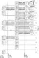
- Figure 2 illustrates an example 200 of a progression of layers through the stages of a system for three-dimensional weaving of composite preforms and products with varying cross-sectional topology according to an embodiment of the invention.
- An embodiment of the invention includes layers of non-fiber material, such as support material, in the fiber preform without having interlayer fibers cross open spaces between non-adjacent layers. This can be used to create overhangs within a part and separate, unconnected parts within a preform.
- interlayer fibers such as interlayer fiber 415 are inserted in regularly spaced rows or columns. Interlayer fibers are inserted only in portions of the preform where the new layer overlaps vertically with all of the layers in the intermediate layer stage. Additionally, each interlayer weaving stage inserts interlayer fibers in only some of the available rows or columns. For example, a weaving phase may insert interlayer fiber 415 and additional interlayer fibers in alternate rows 425A-425C, skipping rows 430A-430D. The omitted rows will be used for interlayer fibers inserted during later weaving phases.
- Figure 7B discussed below, illustrates an example staggered arrangement of interlayer fibers produced by skipping a portion of the rows during each interlayer weaving phase.
- interlayer fibers 765A and 765B Following the addition of interlayer fibers 765A and 765B, all of the rows of openings in layer 761D are now occupied by interlayer fibers (at least for those openings that vertically overlap with the layers above it). Thus, layer 761D is ready for consolidation with layer 763 and interlayer fibers such as 773 may be tightened to eliminate the space between these two layers.
Landscapes
- Engineering & Computer Science (AREA)
- Chemical & Material Sciences (AREA)
- Mechanical Engineering (AREA)
- Materials Engineering (AREA)
- Composite Materials (AREA)
- Manufacturing & Machinery (AREA)
- Textile Engineering (AREA)
- Physics & Mathematics (AREA)
- Optics & Photonics (AREA)
- Woven Fabrics (AREA)
- Looms (AREA)
- Laminated Bodies (AREA)
- Processing And Handling Of Plastics And Other Materials For Molding In General (AREA)
- Moulding By Coating Moulds (AREA)
- Reinforced Plastic Materials (AREA)
Description
- The present invention relates to the field of fiber-reinforced composite materials, and in particular to a method according to
claim 1 for manufacturing fiber preforms with complicated three-dimensional shapes. Fiber-reinforced composite materials, referred to herein as composites, are materials comprised of fibers embedded in a matrix material. Typical fibers include but are not limited to glass fibers, carbon fibers (e.g. graphite fibers and/or more exotic forms of carbon, such as carbon nanotubes), ceramic fibers, and synthetic polymer fibers, such as aramid and ultra-high-molecular-weight polyethylene fibers. Typical matrix materials include but are not limited to polymers, such as epoxies, vinylesters, polyester thermosetting plastics, and phenol formaldehyde resins; cement and concrete; metals; and ceramics. - Composite materials often combine high-strength and relatively light weight. In typical composite products, the fibers provide high tensile strength in one or more directions and the matrix material hold the fibers in a specific shape. A set of fibers roughly in the shape of a final product is referred to as a fiber preform. Typical prior fiber preforms are comprised of layers of fibers (often woven or bound into a sheet of fabric) that are cut and arranged into a desired shape. Because fibers and fabrics made from fibers only provide high strength in specific directions, multiple layers of fiber cloth are often stacked in different orientations to provide strength and stiffness optimized for the intended usage of the final product.
- Most prior composite manufacturing techniques require the production of a mold, mandrel, plug, or other rigid structure in the shape of the desired preform. Sheets of fiber fabric are then cut and arranged on this rigid structure. A matrix material, such as uncured polymer resin, may be embedded in the fiber fabric or applied to the fabric during or after the fabric layup process. The matrix material is then cured or hardened, often under elevated temperature and/or pressure differentials to ensure even distribution of the matrix material and prevent voids, air bubbles, or other internal defects. Pressure and/or temperature may be applied to the composite part during curing using techniques including but not limited to compression molding, vacuum bags, autoclaves, inflatable bladders, and/or curing ovens.
- Unfortunately, prior techniques for manufacturing fiber preforms and final composite parts, especially for complex part shapes, are time-consuming and difficult to automate. For example, creating a mold, mandrel, or other rigid structure for supporting the preform is costly and time-consuming, especially for custom parts or small production runs where the tooling cost and time cannot be amortized over a large number of parts. In addition, the cutting and/or arranging fabric in the mold or other rigid structure is often performed by hand, due to the difficulty in draping fabric over complex forms without wrinkles or other surface defects. As a result, composite products are much more expensive than equivalent products made using conventional materials.
-
JP2006/123277 -
DE19629044 A1 is directed to a flat structure of fibre composite materials and a process for their production. -
US7836917 B1 relates to the creating of a textile product by utilizing a three dimensional Cartesian coordinate system as the infrastructure for weaving simultaneous independent fabric layers in conjunction with weaving connectors between and among the layers. - The invention will be described with reference to the drawings, in which:
-
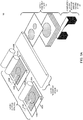
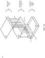
FIGS. 1A-1B illustrate an example arrangement of the stages of a system for three-dimensional weaving of composite preforms and products with varying cross-sectional topology according to an embodiment of the invention; -
FIG. 2 illustrates an example progression of layers through the stages of a system for three-dimensional weaving of composite preforms and products with varying cross-sectional topology according to an embodiment of the invention; -
FIG. 3 illustrates a method of three-dimensional weaving of composite preforms and products with varying cross-sectional topology according to an embodiment of the invention; -
FIG. 4 illustrates an example weaving pattern of interlayer fibers for connecting two or more two-dimensional layers of fibers to form a three-dimensional weave according to an embodiment of the invention; -
FIGS. 5A-5G illustrates the operation of an example mechanism for connecting two or more two-dimensional layers of fibers with an interlayer fibers to form a three-dimensional weave according to an embodiment of the invention; -
FIGS. 6A-6C illustrate the operation of an example mechanism for consolidating two or more layers of a three-dimensional weave according to an embodiment of the invention; -
Figures 7A-7B illustrate example staggered arrangements of interlayer fibers according to an embodiment of the invention; -
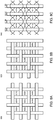
Figures 8A-8C illustrate example open weave fabric patterns suitable for use with embodiments of the invention; -
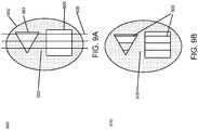
Figures 9A-9E illustrate an example removal of excess interlayer fibers during the consolidation of non-convex layers according to an embodiment of the invention; -
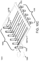
Figures 10A-10D illustrate an example mechanism for supporting and moving layers of fabric during three-dimensional weaving according to an embodiment of the invention; and -
Figure 11 illustrates a computer system suitable for controlling a system for three-dimensional weaving of composite preforms and products with varying cross-sectional topology according to an embodiment of the invention. - Embodiments of the invention include a system and method for created a composite preform with fibers and optionally other interlayer reinforcements interconnected through a three-dimensional weaving pattern. Embodiments of the invention create composite preforms by stacking layers of two-dimensional fiber fabric and then connecting two or more layers of fabric with interlayer fibers. Each layer of fabric may have a different shape than the other layers and any arbitrary topology, potentially including non-convex and/or disjoint shapes.
- An embodiment of the invention stacks first and second material layers separated by a first layer spacing. This embodiment then inserts first interlayer reinforcements through the first and the second material layers and stacks at least a third material layer with at least the first and second material layers. The embodiment then inserts second interlayer reinforcements through at least the second and third material layers. In this embodiment, the first layer spacing between the first and second material layers enables the second interlayer reinforcements to be manipulated during insertion. Following the insertion of at least the second interlayer reinforcement, this embodiment closes the first layer spacing to bring the first and second material layers into contact.
- This technique of adding layers and interlayer reinforcements may be repeated with any arbitrary number of additional layers and interlayer reinforcements to form complex three-dimensionally woven composite preforms.
- Embodiments of the invention include a system and method for created a composite preform with fibers and optionally other reinforcements interconnected through a three-dimensional weaving pattern. Embodiments of the invention create composite preforms by stacking layers of two-dimensional fiber fabric and then connecting two or more layers of fabric with interlayer fibers. Each layer of fabric may have a different shape than the other layers and any arbitrary topology, potentially including non-convex and/or disjoint shapes. Furthermore, embodiments of the invention may produce composite preforms comprised of any arbitrary number of interconnected layers. Further embodiments of the invention may cure composite preforms to produce completed composite parts.
-
Figures 1A-1B illustrate an example arrangement of the stages of a system for three-dimensional weaving of composite preforms and products with varying cross-sectional topology according to an embodiment of the invention.Figure 1A illustrates asystem 100 including one or more layer cutting stages, such aslayer cutting stages layer transport stage 110; alayer assembly stage 115; and a completed layer storage and/orcuring stage 120. - In summary of
system 100, one or more layer cutting stages cut bulk fabric and optionally other materials into the shapes of cross-sections of the desired fiber preform. Thelayer transport stage 110 collects cut cross-section shapes from each of the layer cutting stages and transports them to thelayer assembly stage 115.Layer assembly stage 115 stacks cut cross-section shapes in the correct order and then joins two or more layers of cross-section shapes using interlayer weaving, as described in detail below. After the interlayer weaving process is complete for a given subset of cross-section shapes, they become part of a stack of interwoven fabric layers forming a completed section of the fiber preform and are stored in the completedlayer storage stage 120. -
Layer cutting stage 105A includes a mechanism for dispensing bulk fabric, for example from a bolt or roll offabric 106A, over acutting area 107A. Bulk fabric may include any type of fibers known in the art for use with composite materials. Bulk fabric may be woven or non-woven fabric and may include different types of fibers, such as carbon fibers arranged parallel to one axis and aramid or other fibers arranged parallel to another axis. As described in detail below, embodiments of the bulk fabric is woven or otherwise assembled with gaps or holes between fibers to allow passage of interlayer fibers. Although referred to as a "layer," each cross-section shape may be comprised of two or more physical layers of fabric, potentially bonded together, that are cut and manipulated as a unit, such as a multilayer fabric or sublaminate. - A cutting
head 108A moves over the cuttingarea 107A to cut one or more cross-section shapes 109A from the bulk fabric. Cuttinghead 108A may use any type of cutting mechanism known in the art and suited to cut the fibers included in the bulk fabric, including one or more static or moving blades, cutting lasers, and waterjet cutters. - Each of the cross-section shapes 109A corresponds with the shape of all or a portion of a cross-section of the desired fiber preform. As described above, the cross-section shapes may have any arbitrary topology and include non-convex and/or disjoint shapes. Furthermore, cross-section shapes associated with different layers may have different alignments with respect to the fiber orientation of the bulk fabric, so that as different layers of cross-section shapes are stacked, cross-section shapes may have fiber orientations in different directions.
- An embodiment of
system 100 includes only a singlelayer cutting stage 105A. Further embodiments of the invention include one or more additional layer cutting stages with similar components, such aslayer cutting stage 105B. Each of the optional additional layer cutting stages include similar components, includingbulk fabric 106B, cuttingarea 107B, and cuttinghead 108B to cut one or more cross-section shapes 109B. Embodiments of the invention may include any arbitrary quantity of layer cutting stages operating in parallel to increase the overall speed ofsystem 100. - In yet another embodiment,
system 100 may utilize cross-section shapes cut from different materials. In one implementation, the set of layer cutting stages may be partitioned into two or more subsets, with each subset of layer cutting stages having a different type of bulk fabric material to cut. In another implementation, all or a portion of the layer cutting stages may include two or more rolls of different bulk fabric material and a mechanism for selecting one of the materials to cut. For example,layer cutting stage 105B may includematerial roll 106B and optionally roll 106B'. - In still a further embodiment, materials without fibers may also be included for cutting and incorporation into a fiber preform to support fiber layers during fabrication or to add functional characteristics to the final composite part. For example, a plastic film, such as water-soluble polyvinyl alcohol film, may be included in one or more layers of the fiber preform as a support structure for layers to be added on top of the support layers. After the fiber preform is cured, water or steam may be used to remove these support layers. Other non-fiber materials for cutting and eventual inclusion in layers may include electrically conductive and/or insulating materials; metal foils; magnetic materials; materials adapted to be removed by heat, solvents, or acid; and flexible materials.
- After one or more cross-section shapes for a layer have been cut from the bulk fabric by one of the cutting stages, the
layer transport stage 110 moves the cross-section shapes to an initial position in thelayer assembly stage 115. In an embodiment,layer transport stage 110 includes a conveyor system for transporting cross-section shapes. In another embodiment, a mechanical arm or gantry with one or more degrees of freedom may be used to transport cross-section shapes. - In an embodiment, layer transport stage includes a movable vacuum table platform for picking up cross-section shapes from one or more layer cutting stages and moving these shapes to the
layer assembly stage 115. - If the cross-section shapes do not have any interior voids or openings, then any excess fabric leftover after cutting will remain attached to the roll of bulk fabric. This allows the cross-section shapes to be easily removed from the cutting stage. For more complicated fiber preforms having cross-section shapes with interior voids, embodiments of the
layer transport stage 110 may include a vacuum table or gripper with selectable regions so that cut fabric corresponding with cross-section shapes may be picked up. In this implementation, pieces of cut fabric corresponding with interior voids are left behind in the cutting area and may be swept away. - In still another embodiment, a moveable plate or drum with an electrostatic charge may be used to pick up cross-section shapes. In yet a further embodiment, a photoconductive plate or drum may be given a substantially uniform electrostatic charge and then exposed to a pattern of light corresponding with the inverse of the cross-section shape. The pattern of light causes the electrostatic charge to dissipate outside areas of the plate or drum corresponding with the cross-section shape. The selectively-charged plate or drum may then be used to pick up the cross-section shape while leaving behind unneeded pieces of cut fabric, such as pieces corresponding with interior voids.
-
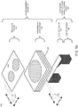
Figure 1B illustrates adetail view 150 of thelayer assembly stage 115 and completed layer storage and/or curingstage 120. As shown indetail view 150, thelayer assembly stage 115 includes anew layer stage 153 and anintermediate layer stage 155.New layer stage 153 receives new cross-section shapes 154 from thelayer transport stage 110 shown infigure 1A .Intermediate layer stage 115 holds at least one and optionally more than one layer. Thelayer assembly stage 115 uses a three-dimensional weaving technique to connect the new cross-section shapes 154 innew layer stage 153 with the one or more layers of previously received cross-section shapes inintermediate layer stage 155 using interlayer fibers. As described in detail below, after the new cross-section shapes 154 in thenew layer stage 153 are connected with the cross-section shapes in the intermediate layer stage, the new cross-section shapes 154 are transferred from thenew layer stage 153 to the top of theintermediate layer stage 155. Additionally, the bottom-most layer of cross-section shapes 160 in theintermediate layer stage 155 is transferred to the completedlayer storage stage 120. - To connect the cross-section shapes 154 in
new layer stage 153 with the cross-section shapes in theintermediate layer stage 155, an embodiment of thelayer assembly stage 115 includes one or more pairs of interlayer weaving arms, such as interlayer weaving arm pair 157 comprised of upper interlayer weaving arm 157A and lower interlayer weaving arm 157B. Upper interlayer weaving arm 157A is adapted to move over the top of new layers innew layer stage 153 in directions 158A and 159A. Similarly, lower interlayer weaving arm 157B moves underneath the stack of cross-section shapes in theintermediate layer stage 155 and over the completedlayer storage stage 120 indirections new layer stage 153 andintermediate layer stage 155. - In an embodiment, completed portions of the fiber preform are stored in the completed
layer storage stage 120. In a further embodiment, resin or other matrix material may be included in the bulk fabric or added to the layers of cross-section shapes during the layer cutting 105,layer transport 110, and/or layer assembly stages 115. In an embodiment, the completedlayer storage stage 120 may optionally include acooling region 163 including a refrigeration or other type of cooling system to prevent resin in the preform from cooling prematurely. - In yet a further embodiment, matrix material included in the fiber preform may optionally be cured or otherwise processed to produce a final product within the completed
layer stage 120. In one implementation of this embodiment, all or a portion of the completed layer stage is heated to accelerate a matrix curing process. In another implementation, the completedlayer storage stage 120 includes acuring region 165 that selectively cures portions of the fiber preform as it moves through this region. The curingregion 165 may include a continuous oven with one or more elevated temperature zones or any other type of curing system known in the art. In this embodiment, the rate of layer cutting and assembling is calibrated so that as new layers are added to the completedlayer storage stage 120, the completed portions of the fiber preform move through the curingregion 165 at a rate appropriate for curing the matrix material. - As discussed above, layers of fiber cloth, which have been cut into cross-section shapes, progress through the layer assembly stage where they are connected with each other using interlayer fibers.
Figure 2 illustrates an example 200 of a progression of layers through the stages of a system for three-dimensional weaving of composite preforms and products with varying cross-sectional topology according to an embodiment of the invention. - Example 200 begins with
phase 205. Inphase 205, a new layer,layer 1 206, is added to thenew layer stage 201.Intermediate stage 202 and completedlayer stage 203 are empty inphase 205. Because there are no layers belowlayer 1 206 for weaving with interlayer fibers,phase 207moves layer 1 206 to theintermediate layer stage 202. -
Phase 209 addslayer 2 210 to thenew layer stage 201. As discussed above, each layer may be comprised of one or more cross-section shapes cut from one or more fiber fabrics. Furthermore, layer's cross-section shapes may include different shapes, different shape topologies, and different fiber orientations than those of the other layers. - Phase 211 weaves
interlayer fibers 212A betweenlayer 2 210 andlayer 1 206. As described in detail below, an upper interlayer weaving arm passes abovelayer 2 210 and a lower interlayer weaving arm passes belowlayer 1 206 to weave these two layers together with interlayer fibers. The two interlayer weaving arms pass individual fibers or untwisted bundles of fibers (sometimes referred to as tows) throughlayers 1 206 and 2 210. In an embodiment, the bulk fabric used to create the cross-section shapes is woven or otherwise assembled with gaps or holes between fibers to allow passage of interlayer fibers. In a further embodiment, cross-section shapes are cut and placed in the layer assembly stage so that the gaps in adjacent fabric layers are aligned. - In prior, two-dimensional weaving techniques, the fibers inserted during the weaving process (sometimes referred to as weft fibers) are normally pulled taut to bind the other fibers (sometimes referred to as warp fibers) together. In contrast, in the embodiment illustrated by example 200, the
interlayer fibers 212A are not pulled taut at this phase so that there is sufficient space for the lower interlayer weaving arm to pass between the layers in a later phase. - Following the weaving of
interlayer fibers 212A inphase 211,phase 213transfers layer 2 210 to theintermediate layer stage 202 andlayer 1 206 to the completedlayer stage 203. In an embodiment,phase 213 may transfer these layers simultaneously so as to maintain the length and tension ofinterlayer fibers 212A. -
Phase 215 addslayer 3 216 to thenew layer stage 201 in a manner similar tophases interlayer fibers 218A betweenlayer 3 216 andlayer 2 210 in a manner similar tophase 211. An upper interlayer weaving arm passes abovelayer 3 216 and a lower interlayer weaving arm passes belowlayer 2 210 to weave these two layers together with interlayer fibers. Because of the spacing left betweenlayers 1 206 and 2 210 in the earlierinterlayer weaving phase 211, there is sufficient space for the lower interlayer weaving arm to pass betweenlayers 1 206 and 2 210 to weaveinterlayer fibers 218A betweenlayers 3 216 and 2 210. - Following the weaving of
interlayer fibers 218A inphase 217,phase 219transfers layer 3 216 to theintermediate layer stage 202 andlayer 2 210 to the completedlayer stage 203. In an embodiment,phase 219 may transfer these layers simultaneously so as to maintain the length and tension ofinterlayer fibers 218A. Additionally, because the completedlayer stage 203 already containslayer 1 206,phase 219 now tightensinterlayer fibers 212A to form tightenedinterlayer fibers 212B. This process of tighteninginterlayer fibers 212A bringslayers 1 206 and 2 210 into contact with each other, eliminating the space previously left between these layers for the lower interlayer weaving arm. This process of tightening a set of interlayer fibers between two layers to bring the layers into contact is referred to as layer consolidation. It should be noted that theinterlayer fibers 218A are not substantially affected by the tightening ofinterlayer fibers 212A and there is still sufficient space betweenlayers 2 210 and 3 216 to allow for the passage of the lower interlayer weaving arm. -
Phase 221 addslayer 4 222 to thenew layer stage 201 in a manner similar tophases interlayer fibers 224A betweenlayer 4 222 andlayer 3 216 in a manner similar tophases layers 2 210 and 3 216 in the earlierinterlayer weaving phase 217, there is sufficient space for the lower interlayer weaving arm to pass betweenlayers 2 210 and 3 216 to weaveinterlayer fibers 224A betweenlayers 4 222 and 3 216. - Following the weaving of
interlayer fibers 224A inphase 223,phase 225transfers layer 4 222 to theintermediate layer stage 202 andlayer 3 216 to the completedlayer stage 203. Phase 225 also tightensinterlayer fibers 218A to form tightenedinterlayer fibers 218B and consolidateslayers 3 216 and 2 210. This brings layers 3 216 and 2 210 into contact with each other while leaving sufficient space betweenlayers 3 216 and 4 222 to allow for the passage of the lower interlayer weaving arm for weaving additional layers. - The process outlined in
phases 205 to 225, and specifically phases 221-225, may be repeated for further layers, allowing a fiber preform to be constructed from any number of fiber layers. - For clarity, example 200 illustrates an
intermediate layer stage 202 holding a single layer at a time. In this example, the interlayer fibers only pass through the new layer and a single intermediate layer. However, further embodiments of the invention may hold multiple layers in theintermediate layer stage 202 at the same time. In these embodiments, the interlayer fibers are woven between the new layer and all of the layers in the intermediate layer stage.Figure 7B illustrate an example arrangement of interlayer fibers passing through multiple intermediate layers. In general, if theintermediate layer stage 202 is able to hold K layers simultaneously, where K is any arbitrary positive integer, then each iteration of an interlayer weaving will pass through the K layers in the intermediate layer stage and the current new layer. Exceptions to this include the first and last K layers of the preform, where the intermediate layer stage may hold less than K layers. -
Figure 3 illustrates amethod 300 of three-dimensional weaving of composite preforms and products with varying cross-sectional topology according to an embodiment of the invention.Method 300 begins withstep 305 generating or retrieving the next cross-section of a digital representation of the preform. A digital representation of the preform may be comprised of three-dimensional computer graphics model data in the form of surface data, such as polygon or triangle meshes, higher-order surfaces such as NURBS or subdivision surfaces, or implicit surfaces; or volumetric models, such as voxel, octree, or solid geometry models. In a further embodiment, the digital representation of the preform includes specifications of fiber orientations at various locations of the preform model. These fiber orientations may be specified based on engineering analysis of the applications of the part. - In an embodiment, the digital representation of the preform has already be partitioned into a set of layer specifications. Each layer specification includes a specification of the shape or shapes comprising the preform cross-section at this location. Each layer specification may optionally include a specification of the fiber orientation for this layer and/or the type of material or materials to be used for this layer (if the system has multiple types of materials installed). Step 305 retrieves this data from memory, data storage, or another computer system.
- In another embodiment,
step 305 generates the cross-section shape of the preform itself directly from the three-dimensional model of the preform using any geometry analysis technique known in the art. For example, Boolean constructive solid geometry operations may be used to generate a cross-section shape from volumetric models and spatial partitioning, such as binary space partitioning trees, may be used to generate a cross-section shape from surface models. If fiber orientations for a specific layer or the entire preform are not specified,step 305 may specify fiber orientations based on heuristics, default patterns, or optimization algorithms using engineering simulations to optimize strength, minimize weight, and/or optimize other factors. - Additionally, if the preform includes disjoint parts or has portions with large, unsupported overhangs, embodiments of
step 305 may retrieve or generate specifications for support material, for example using for meltable, soluble, or otherwise easily removable material. - Step 310 cuts a new layer N according to the cross-section shape and fiber orientation specified by
step 305. In this discussion ofexample method 300, each layer is referred to using a sequential integer N. In some embodiments, the fiber orientation of the bulk fiber material with respect to the cutting area cannot be changed. To compensate for this, the specification of cross-section shape is rotated prior to cutting, such that the desired fiber orientation relative to the cross-section shape is achieved. Additionally, if the bulk fiber includes gaps or holes to accommodate the insertion of interlayer fibers, then step 310 may also translate the cross-section shape such that the holes in this layer will be aligned with those of previously cut layers already in the layer assembly stage. - Step 315 transports the cut cross-section shapes of one or more materials to the new layer stage in the layer assembly stage. In an embodiment,
step 315 rotates and translates the cut cross-section shapes of this layer so that they are aligned with respect to any previously cut layers in the intermediate layer stage of the layer assembly stage. - Step 320 weaves interlayer fiber set Q between layer N and from 1 to K layers in the intermediate layer stage, where K is the maximum number of layers that may be held in the intermediate layer stage and Q is generally equal to N-1. In an embodiment, interlayer fibers are inserted only in portions of the preform where the new layer N overlaps vertically with all of the layers N-1 to N-K in the intermediate layer stage.
- As illustrated in
figure 2 , the system is initialized with an empty intermediate layer stage. In these types of situations, step 320 may be skipped. Once at least one layer is added to the intermediate layer stage, step 320 will weave interlayer fibers between the new layer N and the one or more layers in the intermediate layer stage. Once an initial run of K layers have been created, the intermediate layer stage will include K layers, and step 320 will weave interlayer fibers between the new layer N and the K layers in the intermediate layer stage, which are layers N-1 to layers N-K. The new interlayer fiber set Q is not pulled taut at this time to leave space between the layers for the passage of the lower interlayer weaving arm on subsequent interlayer weaving steps. In an embodiment, the ends of the interlayer fibers are temporarily secured for future access and tightening. - Step 325 moves the new layer N to the top or first position of the intermediate layer stage, moves layer N-K from the bottom or last position of the intermediate layer stage to the completed layer stage, and moves each of the other layers N-1 to N-K+1 in the intermediate layer stage to the next adjacent position in the intermediate layer stage.
- Step 330 tightens a previously woven interlayer fiber set Q-K, if it exists, consolidate layers N-K and N-K-1. Layer consolidation is the process of tightening a set of interlayer fibers between two layers to bring these layers into contact and reduce or substantially eliminate the space between these fiber layers. Additionally, embodiments of
step 330 may trim and remove excess interlayer fibers that are left over after tightening fiber set Q-K. - Step 335 moves the set of layers in the completed layer stage down or away from the intermediate layer stage so to accommodate the addition of further layers. In an embodiment, the completed layer stage includes a moveable platform for supporting the set of interwoven and completed layers. As construction of the fiber preform progresses, the moveable platform moves away from the intermediate layer stage so that the distance between the most recent completed layer and the intermediate layer stage remains roughly constant.
- Step 340 determines if all of the layers of the preform have been cut and added to the layer assembly stage. If not, then
method 300 returns to step 305 to process, cut, and add interlayer weaving to another layer of fabric. If all of the layers have been cut and added to the layer assembly stage, then step 345 determines if there are any layers in the intermediate layer stage left to process. If so, thenmethod 300 proceeds back to step 325 to process additional layers in the intermediate layer stage. Ifstep 345 determines that there are no more layers in the intermediate layer stage, thenmethod 300 is complete. - Although the steps of
method 300 are shown sequentially for clarity, embodiments of the invention may perform some or all of these steps in parallel. For example, an iteration ofsteps steps 315 to 335. In further embodiments, multiple layer cutting stages M may performsteps - In a further embodiment, step 310 may also cut layers of non-fiber material, such as removable support material or materials with other properties, for inclusion with the fiber preform. Support material may be used to support portions of the fiber preform with large overhangs, relative to the layers underneath this portion of the preform. In an additional embodiment, fiber preforms may also be constructed with two or more disjoint parts, optionally held in place through one or more layers of removable (for example meltable or soluble) support material. Each of the disjoint parts has its own layers connected with interlayer fibers, but there are no interlayer fibers connecting the disjoint parts.
- An embodiment of the invention includes layers of non-fiber material, such as support material, in the fiber preform without having interlayer fibers cross open spaces between non-adjacent layers. This can be used to create overhangs within a part and separate, unconnected parts within a preform.
- To accomplish this, the interlayer weaving process, for example shown in
phases new layer stage 201 and moved down through the one or more layer positions of theintermediate layer stage 202 without any interlayer weaving until the first layer of the second part or a fiber layer of an overhanging portion of the preform reaches the bottom of the intermediate layer stage. At this point, interlayer weaving is resumed in this portion of thelayer assembly stage 202 so that layers of the second part and/or overhanging portions of the preform begin to be connected with interlayer fibers. - Embodiments of the invention may include intermediate layer stages having K positions, where K is any integer greater than 1. In general, higher values of K allow for each set of interlayer fibers to span larger numbers of fiber layers, which adds strength along this axis. However, larger values of K also increase the size of the intermediate layer stage and limit minimum thickness of any portion of the fiber preform to K layers. In a further embodiment, this limitation on the minimum thickness of the fiber preform may be overcome by allowing the intermediate layer stage to hold a variable number of fiber layers from 1 to K layers. For thin portions of the fiber preform, the number of fiber layers in the intermediate layer stage is reduces to K', where K' is less than or equal to the thickness of a portion of the fiber preform. When the thickness of the fiber preform increases, K' may be increased up to the maximum value of K to add strength to the preform.
- As described above, interlayer fibers are used to connect layers of fabric cut to cross-section shapes of a fiber preform. These interlayer fibers are not tightened at first to allow for the insertion of additional sets of interlayer fibers between subsequently added layers.
Figure 4 illustrates an example 400 of a weaving pattern of interlayer fibers for connecting two or more two-dimensional layers of fibers to form a three-dimensional weave according to an embodiment of the invention. - In example 400, a
new layer 405 is to be connected with one or more previously addedlayers 410 in positioned in an intermediate layer stage.Interlayer fiber 415 is used to connectlayers new layer 405 to the bottom surface oflayer 410, which would be at the bottom or last position of the intermediate layer stage. For clarity, the interlayer weaving arms passing over the top surface oflayer 405 and under the bottom surface oflayer 410 are omitted from this drawing. - After weaving
interlayer fiber 415, theends space 435 between thelayers layer 405 is at the bottom position of the intermediate layer stage. After the insertion of this subsequent interlayer fiber set, theends interlayer fiber 415 will be used to tighten theinterlayer fiber 415 and remove thespace 435 betweenlayers - In an embodiment, interlayer fibers such as
interlayer fiber 415 are inserted in regularly spaced rows or columns. Interlayer fibers are inserted only in portions of the preform where the new layer overlaps vertically with all of the layers in the intermediate layer stage. Additionally, each interlayer weaving stage inserts interlayer fibers in only some of the available rows or columns. For example, a weaving phase may insertinterlayer fiber 415 and additional interlayer fibers inalternate rows 425A-425C, skippingrows 430A-430D. The omitted rows will be used for interlayer fibers inserted during later weaving phases.Figure 7B , discussed below, illustrates an example staggered arrangement of interlayer fibers produced by skipping a portion of the rows during each interlayer weaving phase. -
Figures 5A-5G illustrates the operation of an example mechanism for connecting two or more two-dimensional layers of fibers with an interlayer fibers to form a three-dimensional weave according to an embodiment of the invention.Figure 5A illustrates a pair offabric layers layer 503 is a new layer added to the layer assembly stage andlayer 505 is at the bottom position of the intermediate layer stage. Althoughfigures 5A-5G only show a pair of layers for clarity, additional layers may be optionally included betweenlayers - A pair of
interlayer weaving arms direction 513 until they reachfirst openings interlayer weaving arms openings openings - In another embodiment, closed loop control systems may be used to move the interlayer weaving arms to predetermined or dynamically determined opening positions. Closed loop system may incorporate position sensors of any type known in the art, including both linear and rotary position and/or distance sensors. Further embodiments of the closed loop control system may include sensors for detecting openings in the fabric layers. Examples of sensors include cameras and computer vision systems and/or lasers and photodetectors mounted on opposite interlayer weaving arms to detect openings in the fabric. In still further embodiments of the invention, there may be markings or other indicators printed on or incorporated within the fabric itself to assist sensors in aligning layers of fabric and locating openings in fabric layers. In yet a further embodiment, conductive and/or magnetic fibers may be included in the fabric layer at known positions relative to the fabric openings and sensed using capacitive, inductive, and/or magnetic sensing techniques.
- Continuing this example in
figure 5B , after aligning the interlayer weaving arms withopenings hollow needles openings rapiers location 521 between thelayers Rapier 515 pulls a fiber or set of fibers (such as a flat ribbon or tow of fibers) 519 from a spool or bobbin over the top surface oflayer 503 and throughopening 511 tolocation 521. Atlocation 521,rapier 517grips fiber 519 andrapier 515releases fiber 519. Fibers may be gripped and released using vacuum tools, mechanical grippers, or any other type of fiber handling mechanism known in the art. In a further embodiment, the end offiber 519 includes magnetic covering so thatrapiers - Continuing this example in
figure 5C ,rapiers openings rapier 517 pullsfiber 519 throughopening 523 so that it is under the bottom surface oflayer 505. Additional fiber from a spool is released to accommodate the movement offiber 519. - Continuing this example in
figure 5D ,interlayer weaving arms direction 513 along the top surface oflayer 503 and the bottom surface oflayer 505, respectively, to the next openings in the fiber layers, 525 and 527. This movement pullsfiber 519 along the bottom surface oflayer 505 toopening 527. - Continuing this example in
figure 5E , after aligning the interlayer weaving arms withopenings rapier arms openings location 529. This pullsfiber 519 throughopening 527 tolocation 529. Atlocation 529,rapier 515grips fiber 519 andrapier 517releases fiber 519. - Continuing this example in
figure 5F ,rapiers openings rapier 517 pullsfiber 519 throughopening 525 so that it is over the top surface oflayer 503. Additional fiber from a spool is released to accommodate the movement offiber 519. - The process shown in
figures 5A-5F is repeated for the remaining openings in these rows offabric layers new layer 503 overlaps vertically withlayer 505 and all the other layers, if any, in the intermediate layer stage.Figure 5G illustrates an example of a completed row of interlayer weaving.Fiber 519 passes through a set of openings in a row offabric layers fiber 519 are secured ingrippers fiber 519 may be pulled taut later to placelayers - The above example shows a pair of interlayer weaving arms weaving a fiber between two (or potentially more) layers. After completing the weaving of this row, the pair of interlayer weaving arms may be retracted and moved to a different row of fabric openings to weave another fiber. This process may be repeated for a portion of the rows of a layer, with some rows of openings typically left open for the weaving of interlayer fibers in subsequent weaving phases between additional layers. In a further embodiment, the system may include multiple pairs of weaving arms operating in parallel to reduce the time required to perform interlayer weaving over multiple rows of openings.
-
Figures 6A-6C illustrate the operation of an example mechanism for consolidating two or more layers of a three-dimensional weave according to an embodiment of the invention. Layer consolidation is the process of tightening a set of interlayer fibers between two layers to bring these layers into contact and reduce or substantially eliminate the space between these fiber layers. -
Figure 6A illustrates a pair oflayers interlayer fiber 607. Interlayer fiber 607 (as well as similar interlayer fibers in other rows oflayers 603 and 605) is secured withgrippers space 609 has been left betweenlayers layer 603 with one or more layers above it using a different row of openings inlayer 603. Once the weaving oflayer 603 with one or more layers above has been completed,layers space 609. -
Figure 6B illustrates an example of the layer consolidation process. In an embodiment,grippers interlayer fiber 607. This tension takes of the slack space betweenlayers space 609 that existed between them. In a further embodiment, interlayer fibers and/or layer fabric may include a coating or lubricant to allow this tightening to occur without binding. - After the
layers excess interlayer fiber layers interlayer fiber 607 as shown infigure 6C . - In a further embodiments, the interlayer weaving arms may insert interlayer fibers using other weaving patterns, such as satin weaves and twill weaves. In still further embodiments, alternative forms of fiber connections may be used to connect layers with interlayer fibers, such as sewing (for example using a lock stitch, chain stitch, or overlock stitch). Embodiments of the invention may be used with any type of fiber connections provided that the connection can be held open to allow for a space between layers and then later tightened to reduce or eliminate this space.
- As discussed above, embodiments of the invention skip rows of openings when weaving interlayer fibers between layers.
Figures 7A-7B illustrate example staggered arrangements of interlayer fibers according to an embodiment of the invention.Figure 7A illustrates an example 700 of staggered interlayer fibers according to an embodiment of the invention. Example 700 includes a pair ofconsolidated layers layer stage 707, at least onelayer 709 in theintermediate layer stage 711, and anew layer 710 in thenew layer stage 712. -
Consolidated layers interlayer fiber 713, which has been tightened to remove the spacing between these layers. Additionally,interlayer fiber 715 connectslayer Interlayer fiber 715 has not been tightened yet, leaving alarge space 717 betweenlayers Space 717 is sufficient for allowing a lowerinterlayer weaving arm 719 to pass betweenlayers Interlayer weaving arm 719 is used to weaveinterlayer fiber 721 betweenlayers interlayer fiber 721 and other fibers betweenlayers layer 709 may be moved to the completed layer stage and consolidated withlayer 705 by tighteninginterlayer fibers 715. - As shown in example 700, each weaving phase may insert interlayer fibers in only a portion of the available rows of openings in the layer fabrics to allow each layer to be connected with layers above and below it using interlayer fibers. For example, if the intermediate layer stage only holds a single layer, then weaving interlayer fibers in alternate rows of openings, as shown in
figure 4 , may be suitable for connecting each layer with those layers above and below it. Infigure 7A , if each weaving phase uses 1/3 of the available row openings, then the intermediate layer stage may hold up to two layers. In this example 700, each layer is connected with the two layers below it. -
Figure 7B illustrates another example 750 of a staggered interlayer fiber arrangement. In example 750, new layer stage 753 includeslayer 759.Intermediate layer stage 755 includes four layers, layers 761A-761D. Completedlayer stage 757 may include any number of layers, including in thisexample layer 763. - In example 750, because there are four layers in the
intermediate layer stage 755, interlayer fibers are woven into each new layer at every fifth row of openings. In a general implementation of this embodiment, if there are K layers in an intermediate layer stage, then interlayer fibers are added to each new layer at every K+1 row of openings. To this end,interlayer fibers new layer 759 andlayer 761D, passing through unused openings inlayers 761A-761C as well. - As
new layer 759 progresses throughintermediate layer stage 755, its unused rows of openings will be gradually filled by interlayer fibers connecting with subsequent layers. For example,layer 761A in the first position of theintermediate layer stage 755 has interlayer fibers in two of every five adjacent rows of openings: such asinterlayer fibers Layer 761B in the second position of theintermediate layer stage 755 has interlayer fibers in three of every five adjacent rows of openings: such asinterlayer fibers Layer 761C in the third position of theintermediate layer stage 755 has interlayer fibers in four of every five adjacent rows of openings: such asinterlayer fibers Layer 761D in the fourth position of theintermediate layer stage 755 has interlayer fibers in all five of every five adjacent rows of openings: such asinterlayer fibers - Following the addition of
interlayer fibers layer 761D are now occupied by interlayer fibers (at least for those openings that vertically overlap with the layers above it). Thus,layer 761D is ready for consolidation withlayer 763 and interlayer fibers such as 773 may be tightened to eliminate the space between these two layers. - As shown in this example 750, by weaving interlayer fibers in every K+1 row of a new layer when the intermediate layer stage has K layers, all of the rows of openings of each layer are occupied with interlayer fibers by the time this new layer progresses through the intermediate layer stage. For each new layer added, the relative phase or offset of the interlayer fiber pattern is changed, but the K+1 interval between rows of interlayer fibers added remains unchanged. In this implementation, interlayer fibers each typically connect K+1 layers.
- In an embodiment illustrated by example 750, interlayer fibers are woven in regular K+1 intervals. However, further embodiments may use other patterns for distributing interlayer fibers, including stochastic patterns of interlayer fibers with statistical distributions corresponding to an average interval of K+1 rows.
- As described above, interlayer fibers are woven through openings of two or more layers.
Figures 8A-8C illustrate example open weave fabric patterns suitable for use with embodiments of the invention.Figure 8A illustrates an example openplain weave pattern 800. Unlike typical plain weaves where the warp and weft fibers are arranged in close contact with each other, openplain weave pattern 800 includes numerous openings suitable for allowing passage of interlayer fibers, such asopenings 805A-805I. -
Figure 8B illustrates an opensatin weave pattern 820. Satin weaves typically have higher strength than plain weaves because the warp fibers are not bent or crimped in every row of the weave. Example opensatin weave pattern 820 is referred to as a four thread satin weave; however, embodiments of the invention may be used with any variation of an open satin weave. Unlike typical satin weaves where the warp and weft fibers are arranged in close contact with each other, opensatin weave pattern 820 includes numerous openings suitable for allowing passage of interlayer fibers, such asopenings 825A-825L. -
Figure 8C illustrates an openleno weave pattern 840. Many open weave patterns allow warp fibers to move positions easily, which can lead to uneven distributions of fibers, referred to as bruising. Leno weave patterns prevent this by twisting warp fibers after one or more weft fibers have been inserted. The twisted warp fibers hold the weft fibers in place while still leaving large spaces between the fibers, such asspaces 841A-841I. - The open
leno weave pattern 840 includes largeprimary fibers 843A-843D. Primary fibers are intended to provide high tensile strength along their axes. Theleno weave pattern 840 also includes twisted secondary fibers 845A-845D intended to hold primary fibers 843 in place. The secondary fibers may be made of the same material as the primary fibers or a different material, such as a less expensive material. When manufactured using traditional weaving processes, the primary fibers 843 will often be weft fibers and the secondary fibers 845 will be warp fibers. -
Figure 8C illustrates a basicleno weave pattern 840. However, further embodiments of the invention may use more complicated leno weaves, such as leno weave patterns where the warp fibers are twisted only after multiple weft fibers have been inserted. In another example, Karamiori or Japanese leno weave patterns may be used to place and hold primary fibers in wide variety of different distributions. Normally, such patterns are used for aesthetic purposes; however, embodiments of the invention may use these patterns to increase or decrease the spacing between primary fibers. - The preceding weave patterns are shown for purposes of illustration and embodiments of the invention may use these and/or any other open fabric patterns known in the art, such as twill weaves, basket weaves, unidirectional weaves, bonded directional weaves, and non-woven fabrics, where fibers or tows are bonded instead of woven together. Additionally, secondary or filling fibers may be included in fabrics to provide support during the weaving process. In a further embodiment, secondary fibers may be adapted to melt, dissolve, or burn away during the curing process.
- As discussed above, following the consolidation of two or more layers, excess interlayer fibers may be cut and removed from the fiber preform.
Figures 9A-9E illustrate an example removal of excess interlayer fibers during the consolidation of non-convex layers according to an embodiment of the invention.Figure 9A illustrates an exampletop view 900 of two layers: alower layer 902 and an upper layer comprised of twodisjoint shapes interlayer fibers 908 pass over the upper layer, including theempty region 905 betweenshapes -
Figure 9B illustrates an exampletop view 910 of the two layers following layer consolidation. Theinterlayer fibers 908 have been trimmed so that they no longercross gap 905. -
Figures 9C-9E illustrate a detailed side view of the trimming of excess fibers during layer consolidation. Infigure 9C , layers 912 and 914 are connected with aninterlayer fiber 916.Layer 912 includes two disjoint portions, separated by agap 918. Before layer consolidation, thisgap 918 is spanned by theinterlayer fiber 916. - In
figure 9D , theinterlayer fiber 916 has been tightened to bringlayers gap 918 is still spanned by theinterlayer fiber 916. - In
figure 9E ,interlayer fiber 916 has been cut intopieces interlayer fiber 916 has been removed from thegap 918. In a further embodiment, excess fiber at the ends ofpieces 916A and/or 916B may be folded over or underlayer 912. - As described above, layers of cut fabric cross-section shapes are moved through the layer assembly stage during interlayer weaving. One mechanism to accomplish this movement is through sets of pins, with each set forming a shelf to support a layer and having openings to accommodate the passage of interlayer fibers. Each set of pins moves down through the positions of the new layer and intermediate layer stages As layer consolidation is performed, the pins retract to the side to allow the layers to contact.
-
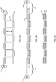
Figures 10A-10D illustrate another example mechanism for supporting and moving layers of fabric during three-dimensional weaving according to an embodiment of the invention.Figure 10A illustrates an example mechanism in aninitial configuration 1000. The example mechanism includesend pieces end pieces supports End piece 1005 is connected with slidingrails end piece 1005 to move to the opposite side ofend piece 1003. Thevertical supports end pieces spool 1009 of high strength fiber, such as nylon fiber, which will be used to form a supporting shelf for a fiber layer in the layer assembly stage. -
Figure 10B illustrates the example mechanism in asecond configuration 1020. In this configuration, theend piece 1005 has moved along slidingrails end piece 1003. Following this movement, afiber anchor 1013 draws afiber 1011 from thespool 1009 across the width ofend pieces Fiber 1011 is surrounded on either side by thevertical supports -
Figure 10C illustrates the example mechanism in athird configuration 1040. In this configuration, theend piece 1005 has moved along slidingrails end piece 1003. In doing so, thevertical supports 1006 ofend piece 1005 have drawn additional amounts offiber 1011 fromspool 1009.Fiber 1011 is held taut using a tension mechanism included inspool 1009 and/orfiber anchor 1013 and forms ashelf 1045 for supporting a fabric layer. - The
end pieces shelf 1045 and the fabric layer that it supports to different positions of this stage. During layer consolidation,fiber 1011 may be released fromanchor 1013 and pulled back on tospool 1009. This causesshelf 1045 to disappear and lets the previously supported fabric layer contact the layer below it. -
Figure 10D illustrates anexample mechanism 1060 for moving retractable fiber support shelves, as described infigures 10A-10C , vertically through a layer assembly stage. according to an embodiment of the invention. In this example 1060, each set of vertical supports can be detached from its respective end piece and attached to a vertically moving chain or conveyor belt in a continuous loop, such asconveyor belt loop 1065. For example, each of the sets of vertical supports, such assupports conveyor belt loop 1065, which moves vertically through the layer assembly stage. (The conveyor belt loop forsupports figure 10B for clarity.) Supports may be attached and detached from end pieces and conveyor belt loops using hooks, latches, magnets, and/or other attachment mechanisms. The conveyor belt loops move in unison through the layer assembly stage, pullingshelves respective supports -
Figure 11 illustrates a computer system suitable 1100 for controlling a system for three-dimensional weaving of composite preforms and products with varying cross-sectional topology according to an embodiment of the invention. Thecomputer system 1100 includes one or more general purpose orspecialized processors 1105, which can include microprocessors, microcontrollers, system on a chip (SoC) devices, digital signal processors, graphics processing units (GPUs), ASICs, and other information processing devices. Thecomputer system 1100 also includesrandom access memory 1110 andnon-volatile memory 1115, such as a magnetic or optical disk drive and/or flash memory devices. - The
computer system 1100 may optionally includes one or morevisual display devices 1120. Thecomputer system 1100 may also optionally include an audio processor 1125 for generating and receiving sound via speakers, microphone, or other audio inputs andoutputs 1130; and optional sensors andinput devices 1140 such as keyboards; scroll wheels; buttons; keypads; touch pads, touch screens, and other touch sensors; joysticks and direction pads; motion sensors, such as accelerometers and gyroscopes; global positioning system (GPS) and other location determining sensors; temperature sensors; such as mechanical, optical, magnetic or other types of position detectors and/or limit switches for detecting the current positions of the various components of the above-described systems; voltage, current, resistance, capacitance, inductance, continuity, or any other type of sensor for measuring electrical characteristics of the various components of the above-described systems; force, acceleration, stress or strain, and/or tension sensors; and/or any other type of input device known in the art.Computer system 1100 may optionally include one or more cameras or otheroptical measurement devices 1135 for capturing still images and/or video. - The
computer system 1100 may also include one or more modems and/or wired or wireless network interfaces 1145 (such as the 802.11 family of network standards) for communicating data via local-area networks 1150; wide-area networks such as the Internet; CDMA, GSM, or other cellular data networks of any generation or protocol; industrial networks; or any other standard or proprietary networks. Thecomputer system 1100 can also include a peripheral and/or data transfer interface, such as wired or wireless USB, IEEE 1394 (Firewire), Bluetooth, or other wired or wireless data transfer interfaces. - The
computer system 1100 can include apower system 1155 for obtaining electrical power from an external source, such as AC line current or DC power tailored to thecomputer system 1100 via an external power supply, as well as one or more rechargeable or one-time use batteries, fuel cells, or any other electrical energy generation device. Additionally,power system 1155 may provide energy in the form of compressed gas, vacuum, and/or hydraulic systems to power various actuators and components of embodiments of the invention. -
Computer system 1100 may be implemented in a variety of different form factors, including desktop and laptop configurations as well as embedded and headless forms. - Embodiments of the invention use a variety of motors and actuators, such as brushed or brushless DC motors, AC synchronous and induction motors, stepper motors, servomotors, solenoids, and/or pneumatic and hydraulic actuators. In an embodiment,
computer system 1100 include motor andactuator controls 1060 for providing power and control signals to these motors and actuators. - Further embodiments can be envisioned to one of ordinary skill in the art. In other embodiments, combinations or sub-combinations of the above disclosed invention can be advantageously made without departing from the scope of the appended claims. The block diagrams of the architecture and flow charts are grouped for ease of understanding. However it should be understood that combinations of blocks, additions of new blocks, re-arrangement of blocks, and the like are contemplated in alternative embodiments of the present invention as set forth in the claims.
- The specification and drawings are, accordingly, to be regarded in an illustrative rather than a restrictive sense. It will, however, be evident that various modifications and changes may be made thereunto without departing from scope of the invention as set forth in the claims.
Claims (14)
- A method of producing a fiber composite preform, the method comprising:stacking first (1 206) and second (2 210) material layers of two-dimensional fiber fabric separated by a first layer spacing;inserting first interlayer fibers (212A) through the first and the second material layers;stacking at least a third (3 216) material layer of two-dimensional fiber fabric with at least the first and second material layers;inserting second interlayer fibers (218A) through at least the second and third material layers, wherein the first layer spacing enables the second interlayer fibers to be manipulated during insertion; andclosing the first layer spacing to bring the first and second material layers into contact.
- The method of claim 1, wherein at least one of the material layers includes a matrix material.
- The method of claim 1, wherein the first and second interlayer fibers include fiber reinforcements.
- The method of claim 3, wherein at least one of the first and second interlayer fibers includes carbon fiber.
- The method of claim 3, wherein inserting the first interlayer fibers includes weaving the first interlayer fibers through the first and second material layers.
- The method of claim 3, wherein:inserting the first interlayer fibers includes securing the first interlayer fibers in a fiber tensioning system; andclosing the first layer spacing includes tensioning the first interlayer fibers using the fiber tensioning system.
- The method of claim 1, wherein at least one of the material layers include openings (511, 523) to allow passage of at least one of the first and/or second interlayer fibers.
- The method of claim 7, wherein:the openings include first openings in the second material layer;inserting the first interlayer fibers includes inserting the first interlayer fibers through a first portion of the first openings in the second material layer; andinserting the second interlayer fibers includes inserting the second interlayer fibers through a second portion of the first openings in the second material layer.
- The method of claim 1, wherein the second interlayer fibers are inserted through at least one additional material layer between the second and third material layers.
- The method of claim 1, wherein stacking at least the third material layer with at least the first and second material layers includes separating the second material layer and the third material layer with a second layer spacing.
- The method of claim 1, wherein the material layers represent cross-sections of at least a portion of a three-dimensional model, wherein at least two of the material layers have different cross-section shapes.
- The method of claim 11, wherein at least one of the material layers includes at least two disjoint cross-sections.
- The method of claim 1, wherein at least one of the material layers includes at least two different materials.
- The method of claim 13, wherein the at least two different materials includes a removable support material.
Applications Claiming Priority (2)
| Application Number | Priority Date | Filing Date | Title |
|---|---|---|---|
| US201361788493P | 2013-03-15 | 2013-03-15 | |
| PCT/US2014/030480 WO2014145675A1 (en) | 2013-03-15 | 2014-03-17 | Methods for three-dimensional weaving of composite preforms and products with varying cross-sectional topology |
Publications (3)
| Publication Number | Publication Date |
|---|---|
| EP2969538A1 EP2969538A1 (en) | 2016-01-20 |
| EP2969538A4 EP2969538A4 (en) | 2016-11-09 |
| EP2969538B1 true EP2969538B1 (en) | 2019-10-30 |
Family
ID=51522155
Family Applications (1)
| Application Number | Title | Priority Date | Filing Date |
|---|---|---|---|
| EP14765732.4A Active EP2969538B1 (en) | 2013-03-15 | 2014-03-17 | Method for producing composite preforms |
Country Status (4)
| Country | Link |
|---|---|
| US (3) | US9527248B2 (en) |
| EP (1) | EP2969538B1 (en) |
| JP (1) | JP6286022B2 (en) |
| WO (1) | WO2014145675A1 (en) |
Families Citing this family (54)
| Publication number | Priority date | Publication date | Assignee | Title |
|---|---|---|---|---|
| US9511543B2 (en) | 2012-08-29 | 2016-12-06 | Cc3D Llc | Method and apparatus for continuous composite three-dimensional printing |
| CN106687858A (en) | 2014-08-03 | 2017-05-17 | 波戈技术有限公司 | Wearable camera systems and apparatus and method for attaching camera systems or other electronic devices to wearable articles |
| NL2013687B1 (en) * | 2014-10-27 | 2016-10-04 | Stichting Vu-Vumc | Method of layered object manufacturing, sheet element, object manufacturing device, and object. |
| CN106217878B (en) * | 2015-01-27 | 2019-01-04 | 王恩慧 | A kind of 3D printer printing carbon fiber |
| DE102015105533A1 (en) * | 2015-04-10 | 2016-10-13 | Technische Universität Dresden | Textile structure and process for its production |
| JP6642918B2 (en) * | 2016-07-14 | 2020-02-12 | 三菱重工業株式会社 | Method of assembling joining member and joining member |
| US10625467B2 (en) | 2016-09-06 | 2020-04-21 | Continuous Composites Inc. | Additive manufacturing system having adjustable curing |
| US20180065317A1 (en) | 2016-09-06 | 2018-03-08 | Cc3D Llc | Additive manufacturing system having in-situ fiber splicing |
| US10901386B2 (en) | 2016-09-06 | 2021-01-26 | Continuous Composites Inc. | Systems and methods for controlling additive manufacturing |
| US10759113B2 (en) | 2016-09-06 | 2020-09-01 | Continuous Composites Inc. | Additive manufacturing system having trailing cure mechanism |
| US10543640B2 (en) | 2016-09-06 | 2020-01-28 | Continuous Composites Inc. | Additive manufacturing system having in-head fiber teasing |
| US10717207B2 (en) | 2016-10-24 | 2020-07-21 | Gregory D. Vialle | 3D printer |
| US10773783B2 (en) | 2016-11-03 | 2020-09-15 | Continuous Composites Inc. | Composite vehicle body |
| US20210094230A9 (en) | 2016-11-04 | 2021-04-01 | Continuous Composites Inc. | System for additive manufacturing |
| US10953598B2 (en) | 2016-11-04 | 2021-03-23 | Continuous Composites Inc. | Additive manufacturing system having vibrating nozzle |
| US10040240B1 (en) | 2017-01-24 | 2018-08-07 | Cc3D Llc | Additive manufacturing system having fiber-cutting mechanism |
| US10857726B2 (en) | 2017-01-24 | 2020-12-08 | Continuous Composites Inc. | Additive manufacturing system implementing anchor curing |
| US20180229092A1 (en) | 2017-02-13 | 2018-08-16 | Cc3D Llc | Composite sporting equipment |
| US10798783B2 (en) | 2017-02-15 | 2020-10-06 | Continuous Composites Inc. | Additively manufactured composite heater |
| WO2018156521A1 (en) * | 2017-02-21 | 2018-08-30 | Seriforge, Inc. | Systems and methods of converting fiber into shaped fabric plies for composite preforms and products |
| US10906240B2 (en) | 2017-06-29 | 2021-02-02 | Continuous Composites Inc. | Print head for additive manufacturing system |
| US10814569B2 (en) | 2017-06-29 | 2020-10-27 | Continuous Composites Inc. | Method and material for additive manufacturing |
| US10319499B1 (en) | 2017-11-30 | 2019-06-11 | Cc3D Llc | System and method for additively manufacturing composite wiring harness |
| US10131088B1 (en) | 2017-12-19 | 2018-11-20 | Cc3D Llc | Additive manufacturing method for discharging interlocking continuous reinforcement |
| US11167495B2 (en) | 2017-12-29 | 2021-11-09 | Continuous Composites Inc. | System and method for additively manufacturing functional elements into existing components |
| US10081129B1 (en) | 2017-12-29 | 2018-09-25 | Cc3D Llc | Additive manufacturing system implementing hardener pre-impregnation |
| US10759114B2 (en) | 2017-12-29 | 2020-09-01 | Continuous Composites Inc. | System and print head for continuously manufacturing composite structure |
| US10857729B2 (en) | 2017-12-29 | 2020-12-08 | Continuous Composites Inc. | System and method for additively manufacturing functional elements into existing components |
| US10919222B2 (en) | 2017-12-29 | 2021-02-16 | Continuous Composites Inc. | System and method for additively manufacturing functional elements into existing components |
| US10988340B2 (en) * | 2018-03-09 | 2021-04-27 | Advanced Composites, Inc. | Fracking tools and methods of forming the same |
| US11161300B2 (en) | 2018-04-11 | 2021-11-02 | Continuous Composites Inc. | System and print head for additive manufacturing system |
| US11130284B2 (en) | 2018-04-12 | 2021-09-28 | Continuous Composites Inc. | System and head for continuously manufacturing composite structure |
| US11110656B2 (en) | 2018-04-12 | 2021-09-07 | Continuous Composites Inc. | System for continuously manufacturing composite structure |
| US11052603B2 (en) | 2018-06-07 | 2021-07-06 | Continuous Composites Inc. | Additive manufacturing system having stowable cutting mechanism |
| US20200086563A1 (en) | 2018-09-13 | 2020-03-19 | Cc3D Llc | System and head for continuously manufacturing composite structure |
| US11235522B2 (en) | 2018-10-04 | 2022-02-01 | Continuous Composites Inc. | System for additively manufacturing composite structures |
| US11511480B2 (en) | 2018-10-26 | 2022-11-29 | Continuous Composites Inc. | System for additive manufacturing |
| US11420390B2 (en) | 2018-11-19 | 2022-08-23 | Continuous Composites Inc. | System for additively manufacturing composite structure |
| US11358331B2 (en) | 2018-11-19 | 2022-06-14 | Continuous Composites Inc. | System and head for continuously manufacturing composite structure |
| US20200238603A1 (en) | 2019-01-25 | 2020-07-30 | Continuous Composites Inc. | System for additively manufacturing composite structure |
| US20200376758A1 (en) | 2019-05-28 | 2020-12-03 | Continuous Composites Inc. | System for additively manufacturing composite structure |
| US11840022B2 (en) | 2019-12-30 | 2023-12-12 | Continuous Composites Inc. | System and method for additive manufacturing |
| US11904534B2 (en) | 2020-02-25 | 2024-02-20 | Continuous Composites Inc. | Additive manufacturing system |
| US11535962B2 (en) | 2020-05-21 | 2022-12-27 | Raytheon Technologies Corporation | Weaving assembly and method of using |
| US11760030B2 (en) | 2020-06-23 | 2023-09-19 | Continuous Composites Inc. | Systems and methods for controlling additive manufacturing |
| ES2954755T3 (en) * | 2020-07-24 | 2023-11-24 | Fundacion Tecnalia Res & Innovation | Method for the manufacture of polymeric composite materials with embedded functionalities |
| US12083741B2 (en) | 2020-09-11 | 2024-09-10 | Continous Composites Inc. | Print heads for additive manufacturing systems |
| CN112277338B (en) * | 2020-09-30 | 2022-04-26 | 陕西科技大学 | Device and method for efficiently reinforcing composite material by continuous fibers at any angle |
| US11926099B2 (en) | 2021-04-27 | 2024-03-12 | Continuous Composites Inc. | Additive manufacturing system |
| EP4108422A1 (en) * | 2021-06-25 | 2022-12-28 | GKN Aerospace Deutschland GmbH | Fibre interlayers |
| US20230118530A1 (en) | 2021-10-20 | 2023-04-20 | Continuous Composites Inc. | Systems and methods for additive manufacturing |
| US12600084B2 (en) | 2022-05-12 | 2026-04-14 | Continuous Composites Inc. | Additive manufacturing system |
| GB202210820D0 (en) | 2022-07-25 | 2022-09-07 | Rolls Royce Plc | Composite component, method of manufacturing a preform for the component |
| GB202210823D0 (en) * | 2022-07-25 | 2022-09-07 | Rolls Royce Plc | Woven structure and method of manufacture |
Citations (1)
| Publication number | Priority date | Publication date | Assignee | Title |
|---|---|---|---|---|
| US7836917B1 (en) * | 2009-11-18 | 2010-11-23 | Paradox LLC | Weaving connectors for three dimensional textile products |
Family Cites Families (43)
| Publication number | Priority date | Publication date | Assignee | Title |
|---|---|---|---|---|
| US3769142A (en) * | 1970-12-04 | 1973-10-30 | Mc Donnell Douglas Corp | Non-woven locked ply composite structure |
| US4038440A (en) | 1972-01-24 | 1977-07-26 | Avco Corporation | Three dimensional fabric material |
| JPS5239473B2 (en) * | 1972-05-19 | 1977-10-05 | ||
| US4285752A (en) * | 1980-03-13 | 1981-08-25 | Camsco, Inc. | Automatic tape lay-up system |
| US4622254A (en) * | 1981-08-31 | 1986-11-11 | Toray Industries, Inc. | Fiber material for reinforcing plastics |
| DE3246803A1 (en) | 1982-12-17 | 1984-06-20 | Messerschmitt-Bölkow-Blohm GmbH, 8000 München | METHOD FOR PRODUCING COMPONENTS FROM LAYERS OF FIBER REINFORCED PLASTIC |
| JPS6045632A (en) * | 1983-08-19 | 1985-03-12 | 帝人株式会社 | Composite fiber structure for thermal molding |
| US4550045A (en) * | 1983-09-28 | 1985-10-29 | Knytex Proform | Biased multi-layer structural fabric composites stitched in a vertical direction |
| US4571355A (en) * | 1984-11-28 | 1986-02-18 | The Boeing Company | Fiber reinforced resin composites formed of basic ply blankets |
| US4752352A (en) | 1986-06-06 | 1988-06-21 | Michael Feygin | Apparatus and method for forming an integral object from laminations |
| US4842787A (en) | 1986-12-22 | 1989-06-27 | Xerkon, Inc. | High speed process for production of oriented structural yarn/polymer matrix composite structural parts |
| US4774120A (en) | 1987-03-09 | 1988-09-27 | Xerkon, Inc. | Method for multiple-end-close-set uniform density parallel weft insertion and products thereof |
| DE3872911T2 (en) * | 1987-03-31 | 1992-12-03 | Asahi Chemical Ind | FABRICS WITH A MULTILAYER STRUCTURE AND A COMPOSITE MATERIAL CONTAINING THIS FABRIC. |
| US4808461A (en) | 1987-12-14 | 1989-02-28 | Foster-Miller, Inc. | Composite structure reinforcement |
| US4867086A (en) | 1988-07-21 | 1989-09-19 | Xerkon, Inc. | Method of making a dry fiber form and composites prepared therefrom |
| US5024862A (en) | 1988-09-30 | 1991-06-18 | The Boeing Company | Automated cutting and kitting system of composite material and method |
| US4992317A (en) | 1988-12-22 | 1991-02-12 | Xerkon, Inc. | Reinforced three dimensional composite parts of complex shape and method of making |
| US5080851A (en) * | 1990-09-06 | 1992-01-14 | United Technologies Corporation | Method for stabilizing complex composite preforms |
| US5211967A (en) * | 1991-03-15 | 1993-05-18 | Kabushiki Kaisha Toyoda Jidoshokki Seisakusho | Three-dimensional fabric and method of producing the same |
| JPH0819594B2 (en) * | 1991-10-17 | 1996-02-28 | 株式会社豊田自動織機製作所 | Three-dimensional fabric for composite materials |
| US5327621A (en) * | 1992-03-23 | 1994-07-12 | Kabushiki Kaisha Toyoda Jidoshokki Seisakusho | Method of producing fabric reinforcing matrix for composites |
| US5466506A (en) | 1992-10-27 | 1995-11-14 | Foster-Miller, Inc. | Translaminar reinforcement system for Z-direction reinforcement of a fiber matrix structure |
| DE19629044C2 (en) | 1995-07-19 | 1998-12-03 | Deutsch Zentr Luft & Raumfahrt | Flat structure made of fiber composite materials and process for their production |
| US5980665A (en) | 1996-05-31 | 1999-11-09 | The Boeing Company | Z-pin reinforced bonds for connecting composite structures |
| KR100491512B1 (en) | 1997-03-03 | 2005-05-27 | 비팀 아베 | Woven 3d fabric material and a device for producing it |
| US6431222B1 (en) | 1997-03-03 | 2002-08-13 | Biteam Ab | Network-like woven 3D fabric material |
| US6742547B2 (en) | 2000-09-20 | 2004-06-01 | Bally Ribbon Mills | Three-dimensional woven forms with integral bias fibers and bias weaving loom |
| US6315007B1 (en) | 2001-03-23 | 2001-11-13 | 3Tex, Inc. | High speed three-dimensional weaving method and machine |
| US6645333B2 (en) | 2001-04-06 | 2003-11-11 | Ebert Composites Corporation | Method of inserting z-axis reinforcing fibers into a composite laminate |
| JP2002309008A (en) * | 2001-04-18 | 2002-10-23 | Tochigi Prefecture | Heat dissipation plate made of carbon fiber reinforced plastic based on multiple fabrics organized by carbon fiber |
| KR100384135B1 (en) * | 2001-07-06 | 2003-05-14 | 한국과학기술원 | Transfer Type Variable Lamination Manufacturing by using Linear Heat Cutting System And Apparatus Thereof |
| FR2836690B1 (en) * | 2002-03-04 | 2004-08-27 | Eads Launch Vehicles | PROCESS FOR THE PRODUCTION OF A DOUBLE-WALL THERMOSTRUCTURAL COMPOSITE MONOLITHIC PIECE AND PART OBTAINED |
| US7478650B2 (en) * | 2002-06-19 | 2009-01-20 | Saint-Gobain Technical Fabrics Canada, Ltd. | Inversion liner and liner components for conduits |
| US20040219855A1 (en) | 2003-05-02 | 2004-11-04 | Tsotsis Thomas K. | Highly porous interlayers to toughen liquid-molded fabric-based composites |
| JP2006123277A (en) * | 2004-10-27 | 2006-05-18 | Mitsubishi Heavy Ind Ltd | Frp structure, frp windmill blade, and method for joining frp hollow member |
| WO2006121961A1 (en) * | 2005-05-09 | 2006-11-16 | Cytec Technology Corp. | Resin-soluble thermoplastic veil for composite materials |
| US7409757B2 (en) | 2005-06-22 | 2008-08-12 | Northrop Grumman Corporation | Automated Z-pin insertion technique using universal insertion parameters |
| FR2902803B1 (en) * | 2006-06-21 | 2008-11-14 | Snecma Propulsion Solide Sa | FIBROUS REINFORCING STRUCTURE FOR A PIECE OF COMPOSITE MATERIAL AND PART COMPRISING THE SAME |
| FR2907707B1 (en) * | 2006-10-26 | 2009-01-30 | Snecma Sa | PROCESS FOR MANUFACTURING A WINDOW WINDOW IN COMPOSITE MATERIAL |
| CN101168926A (en) * | 2006-10-27 | 2008-04-30 | 韩楠林 | Fiber product and manufacturing and application method thereof |
| US7981495B2 (en) | 2006-10-31 | 2011-07-19 | Invensys Systems, Inc. | Materials methodology to improve the delamination strength of laminar composites |
| EP3345744B1 (en) | 2011-08-29 | 2024-06-26 | Impossible Objects, Inc. | Methods and apparatus for 3d fabrication |
| CA2867860A1 (en) | 2012-04-02 | 2013-10-10 | William Anton TRONDL | Method of making a 3d object from composite material |
-
2014
- 2014-03-17 US US14/216,472 patent/US9527248B2/en not_active Expired - Fee Related
- 2014-03-17 JP JP2016503408A patent/JP6286022B2/en not_active Expired - Fee Related
- 2014-03-17 US US14/216,406 patent/US9381702B2/en not_active Expired - Fee Related
- 2014-03-17 EP EP14765732.4A patent/EP2969538B1/en active Active
- 2014-03-17 WO PCT/US2014/030480 patent/WO2014145675A1/en not_active Ceased
-
2016
- 2016-11-08 US US15/346,701 patent/US10239235B2/en not_active Expired - Fee Related
Patent Citations (1)
| Publication number | Priority date | Publication date | Assignee | Title |
|---|---|---|---|---|
| US7836917B1 (en) * | 2009-11-18 | 2010-11-23 | Paradox LLC | Weaving connectors for three dimensional textile products |
Also Published As
| Publication number | Publication date |
|---|---|
| US20170050340A1 (en) | 2017-02-23 |
| US9381702B2 (en) | 2016-07-05 |
| JP6286022B2 (en) | 2018-02-28 |
| US10239235B2 (en) | 2019-03-26 |
| WO2014145675A1 (en) | 2014-09-18 |
| US20140265020A1 (en) | 2014-09-18 |
| US20140262047A1 (en) | 2014-09-18 |
| US9527248B2 (en) | 2016-12-27 |
| EP2969538A4 (en) | 2016-11-09 |
| EP2969538A1 (en) | 2016-01-20 |
| JP2016522757A (en) | 2016-08-04 |
Similar Documents
| Publication | Publication Date | Title |
|---|---|---|
| US10239235B2 (en) | Systems for three-dimensional weaving of composite preforms and products with varying cross-sectional topology | |
| Cox et al. | Handbook of analytical methods for textile composites | |
| AU2019246864B2 (en) | Composite structures constructed of wound tubular braiding | |
| Wang et al. | Experimental and numerical analyses of manufacturing process of a composite square box part: Comparison between textile reinforcement forming and surface 3D weaving | |
| Wambua et al. | A review of preforms for the composites industry | |
| US11213995B2 (en) | Composite structures constructed of wound tubular braiding | |
| US10773469B2 (en) | Systems and methods of converting fiber into shaped fabric plies for composite preforms and products | |
| US11345099B2 (en) | Composite structures constructed of wound tubular braiding | |
| CN101379237A (en) | Three-dimensional textile component structure consisting of high-tensile threads and method for producing said structure | |
| AU2013221734A1 (en) | Pi-shaped preform with bias fibers | |
| US10407262B2 (en) | Fabric positioning apparatus | |
| Yao et al. | A 3D weaving infill pattern for fused filament fabrication | |
| US20160059513A1 (en) | Folded composite preforms with integrated joints | |
| US20180126598A1 (en) | Method and system for automated fabrication of composite preforms | |
| Li | On the structural mechanics of 3-D braided preforms for composites | |
| US20190322059A1 (en) | Method and system for fabrication of composite preforms | |
| EP3647026B1 (en) | Composite structures constructed of wound tubular braiding | |
| US10239281B2 (en) | System and method for pinning fiber material | |
| EP3647028A1 (en) | Composite structures constructed of wound tubular braiding | |
| Jetavat | Near net shape preforming by 3D weaving process | |
| EP3647034B1 (en) | Apparatus and method for fabricating a composite structure of wound tubular braiding | |
| NL2022171B1 (en) | Composite structures constructed of wound tubular braiding | |
| Gessler | Braided reinforcements for composites | |
| Zhu et al. | Hollow/Porous Three-Dimensional Woven Structure Reinforced Composites | |
| Cahuzac | Aerospatiale Processes for Three-Dimensional Preforms |
Legal Events
| Date | Code | Title | Description |
|---|---|---|---|
| PUAI | Public reference made under article 153(3) epc to a published international application that has entered the european phase |
Free format text: ORIGINAL CODE: 0009012 |
|
| 17P | Request for examination filed |
Effective date: 20151015 |
|
| AK | Designated contracting states |
Kind code of ref document: A1 Designated state(s): AL AT BE BG CH CY CZ DE DK EE ES FI FR GB GR HR HU IE IS IT LI LT LU LV MC MK MT NL NO PL PT RO RS SE SI SK SM TR |
|
| AX | Request for extension of the european patent |
Extension state: BA ME |
|
| DAX | Request for extension of the european patent (deleted) | ||
| A4 | Supplementary search report drawn up and despatched |
Effective date: 20161007 |
|
| RIC1 | Information provided on ipc code assigned before grant |
Ipc: B32B 7/08 20060101AFI20161003BHEP |
|
| STAA | Information on the status of an ep patent application or granted ep patent |
Free format text: STATUS: EXAMINATION IS IN PROGRESS |
|
| 17Q | First examination report despatched |
Effective date: 20181128 |
|
| REG | Reference to a national code |
Ref country code: DE Ref legal event code: R079 Ref document number: 602014055974 Country of ref document: DE Free format text: PREVIOUS MAIN CLASS: B32B0007080000 Ipc: B29C0064147000 |
|
| RIC1 | Information provided on ipc code assigned before grant |
Ipc: B29C 64/141 20170101ALI20190418BHEP Ipc: B29C 70/24 20060101ALI20190418BHEP Ipc: B29C 64/147 20170101AFI20190418BHEP Ipc: B33Y 10/00 20150101ALI20190418BHEP Ipc: B29C 70/30 20060101ALI20190418BHEP Ipc: B29B 11/16 20060101ALI20190418BHEP Ipc: B29C 70/54 20060101ALI20190418BHEP |
|
| GRAP | Despatch of communication of intention to grant a patent |
Free format text: ORIGINAL CODE: EPIDOSNIGR1 |
|
| STAA | Information on the status of an ep patent application or granted ep patent |
Free format text: STATUS: GRANT OF PATENT IS INTENDED |
|
| INTG | Intention to grant announced |
Effective date: 20190527 |
|
| GRAS | Grant fee paid |
Free format text: ORIGINAL CODE: EPIDOSNIGR3 |
|
| GRAA | (expected) grant |
Free format text: ORIGINAL CODE: 0009210 |
|
| STAA | Information on the status of an ep patent application or granted ep patent |
Free format text: STATUS: THE PATENT HAS BEEN GRANTED |
|
| AK | Designated contracting states |
Kind code of ref document: B1 Designated state(s): AL AT BE BG CH CY CZ DE DK EE ES FI FR GB GR HR HU IE IS IT LI LT LU LV MC MK MT NL NO PL PT RO RS SE SI SK SM TR |
|
| REG | Reference to a national code |
Ref country code: GB Ref legal event code: FG4D |
|
| REG | Reference to a national code |
Ref country code: CH Ref legal event code: EP |
|
| REG | Reference to a national code |
Ref country code: DE Ref legal event code: R096 Ref document number: 602014055974 Country of ref document: DE |
|
| REG | Reference to a national code |
Ref country code: AT Ref legal event code: REF Ref document number: 1195674 Country of ref document: AT Kind code of ref document: T Effective date: 20191115 |
|
| REG | Reference to a national code |
Ref country code: IE Ref legal event code: FG4D |
|
| REG | Reference to a national code |
Ref country code: LT Ref legal event code: MG4D |
|
| PG25 | Lapsed in a contracting state [announced via postgrant information from national office to epo] |
Ref country code: ES Free format text: LAPSE BECAUSE OF FAILURE TO SUBMIT A TRANSLATION OF THE DESCRIPTION OR TO PAY THE FEE WITHIN THE PRESCRIBED TIME-LIMIT Effective date: 20191030 Ref country code: LV Free format text: LAPSE BECAUSE OF FAILURE TO SUBMIT A TRANSLATION OF THE DESCRIPTION OR TO PAY THE FEE WITHIN THE PRESCRIBED TIME-LIMIT Effective date: 20191030 Ref country code: SE Free format text: LAPSE BECAUSE OF FAILURE TO SUBMIT A TRANSLATION OF THE DESCRIPTION OR TO PAY THE FEE WITHIN THE PRESCRIBED TIME-LIMIT Effective date: 20191030 Ref country code: GR Free format text: LAPSE BECAUSE OF FAILURE TO SUBMIT A TRANSLATION OF THE DESCRIPTION OR TO PAY THE FEE WITHIN THE PRESCRIBED TIME-LIMIT Effective date: 20200131 Ref country code: PL Free format text: LAPSE BECAUSE OF FAILURE TO SUBMIT A TRANSLATION OF THE DESCRIPTION OR TO PAY THE FEE WITHIN THE PRESCRIBED TIME-LIMIT Effective date: 20191030 Ref country code: NO Free format text: LAPSE BECAUSE OF FAILURE TO SUBMIT A TRANSLATION OF THE DESCRIPTION OR TO PAY THE FEE WITHIN THE PRESCRIBED TIME-LIMIT Effective date: 20200130 Ref country code: LT Free format text: LAPSE BECAUSE OF FAILURE TO SUBMIT A TRANSLATION OF THE DESCRIPTION OR TO PAY THE FEE WITHIN THE PRESCRIBED TIME-LIMIT Effective date: 20191030 Ref country code: BG Free format text: LAPSE BECAUSE OF FAILURE TO SUBMIT A TRANSLATION OF THE DESCRIPTION OR TO PAY THE FEE WITHIN THE PRESCRIBED TIME-LIMIT Effective date: 20200130 Ref country code: FI Free format text: LAPSE BECAUSE OF FAILURE TO SUBMIT A TRANSLATION OF THE DESCRIPTION OR TO PAY THE FEE WITHIN THE PRESCRIBED TIME-LIMIT Effective date: 20191030 Ref country code: NL Free format text: LAPSE BECAUSE OF FAILURE TO SUBMIT A TRANSLATION OF THE DESCRIPTION OR TO PAY THE FEE WITHIN THE PRESCRIBED TIME-LIMIT Effective date: 20191030 Ref country code: PT Free format text: LAPSE BECAUSE OF FAILURE TO SUBMIT A TRANSLATION OF THE DESCRIPTION OR TO PAY THE FEE WITHIN THE PRESCRIBED TIME-LIMIT Effective date: 20200302 |
|
| REG | Reference to a national code |
Ref country code: NL Ref legal event code: MP Effective date: 20191030 |
|
| PG25 | Lapsed in a contracting state [announced via postgrant information from national office to epo] |
Ref country code: RS Free format text: LAPSE BECAUSE OF FAILURE TO SUBMIT A TRANSLATION OF THE DESCRIPTION OR TO PAY THE FEE WITHIN THE PRESCRIBED TIME-LIMIT Effective date: 20191030 Ref country code: IS Free format text: LAPSE BECAUSE OF FAILURE TO SUBMIT A TRANSLATION OF THE DESCRIPTION OR TO PAY THE FEE WITHIN THE PRESCRIBED TIME-LIMIT Effective date: 20200229 Ref country code: HR Free format text: LAPSE BECAUSE OF FAILURE TO SUBMIT A TRANSLATION OF THE DESCRIPTION OR TO PAY THE FEE WITHIN THE PRESCRIBED TIME-LIMIT Effective date: 20191030 |
|
| PG25 | Lapsed in a contracting state [announced via postgrant information from national office to epo] |
Ref country code: AL Free format text: LAPSE BECAUSE OF FAILURE TO SUBMIT A TRANSLATION OF THE DESCRIPTION OR TO PAY THE FEE WITHIN THE PRESCRIBED TIME-LIMIT Effective date: 20191030 |
|
| PG25 | Lapsed in a contracting state [announced via postgrant information from national office to epo] |
Ref country code: EE Free format text: LAPSE BECAUSE OF FAILURE TO SUBMIT A TRANSLATION OF THE DESCRIPTION OR TO PAY THE FEE WITHIN THE PRESCRIBED TIME-LIMIT Effective date: 20191030 Ref country code: DK Free format text: LAPSE BECAUSE OF FAILURE TO SUBMIT A TRANSLATION OF THE DESCRIPTION OR TO PAY THE FEE WITHIN THE PRESCRIBED TIME-LIMIT Effective date: 20191030 Ref country code: RO Free format text: LAPSE BECAUSE OF FAILURE TO SUBMIT A TRANSLATION OF THE DESCRIPTION OR TO PAY THE FEE WITHIN THE PRESCRIBED TIME-LIMIT Effective date: 20191030 Ref country code: CZ Free format text: LAPSE BECAUSE OF FAILURE TO SUBMIT A TRANSLATION OF THE DESCRIPTION OR TO PAY THE FEE WITHIN THE PRESCRIBED TIME-LIMIT Effective date: 20191030 |
|
| REG | Reference to a national code |
Ref country code: DE Ref legal event code: R097 Ref document number: 602014055974 Country of ref document: DE |
|
| REG | Reference to a national code |
Ref country code: AT Ref legal event code: MK05 Ref document number: 1195674 Country of ref document: AT Kind code of ref document: T Effective date: 20191030 |
|
| PG25 | Lapsed in a contracting state [announced via postgrant information from national office to epo] |
Ref country code: SM Free format text: LAPSE BECAUSE OF FAILURE TO SUBMIT A TRANSLATION OF THE DESCRIPTION OR TO PAY THE FEE WITHIN THE PRESCRIBED TIME-LIMIT Effective date: 20191030 Ref country code: SK Free format text: LAPSE BECAUSE OF FAILURE TO SUBMIT A TRANSLATION OF THE DESCRIPTION OR TO PAY THE FEE WITHIN THE PRESCRIBED TIME-LIMIT Effective date: 20191030 Ref country code: IT Free format text: LAPSE BECAUSE OF FAILURE TO SUBMIT A TRANSLATION OF THE DESCRIPTION OR TO PAY THE FEE WITHIN THE PRESCRIBED TIME-LIMIT Effective date: 20191030 |
|
| PLBE | No opposition filed within time limit |
Free format text: ORIGINAL CODE: 0009261 |
|
| STAA | Information on the status of an ep patent application or granted ep patent |
Free format text: STATUS: NO OPPOSITION FILED WITHIN TIME LIMIT |
|
| REG | Reference to a national code |
Ref country code: DE Ref legal event code: R119 Ref document number: 602014055974 Country of ref document: DE |
|
| 26N | No opposition filed |
Effective date: 20200731 |
|
| PG25 | Lapsed in a contracting state [announced via postgrant information from national office to epo] |
Ref country code: MC Free format text: LAPSE BECAUSE OF FAILURE TO SUBMIT A TRANSLATION OF THE DESCRIPTION OR TO PAY THE FEE WITHIN THE PRESCRIBED TIME-LIMIT Effective date: 20191030 |
|
| REG | Reference to a national code |
Ref country code: CH Ref legal event code: PL |
|
| PG25 | Lapsed in a contracting state [announced via postgrant information from national office to epo] |
Ref country code: SI Free format text: LAPSE BECAUSE OF FAILURE TO SUBMIT A TRANSLATION OF THE DESCRIPTION OR TO PAY THE FEE WITHIN THE PRESCRIBED TIME-LIMIT Effective date: 20191030 Ref country code: AT Free format text: LAPSE BECAUSE OF FAILURE TO SUBMIT A TRANSLATION OF THE DESCRIPTION OR TO PAY THE FEE WITHIN THE PRESCRIBED TIME-LIMIT Effective date: 20191030 |
|
| REG | Reference to a national code |
Ref country code: BE Ref legal event code: MM Effective date: 20200331 |
|
| PG25 | Lapsed in a contracting state [announced via postgrant information from national office to epo] |
Ref country code: LU Free format text: LAPSE BECAUSE OF NON-PAYMENT OF DUE FEES Effective date: 20200317 |
|
| PG25 | Lapsed in a contracting state [announced via postgrant information from national office to epo] |
Ref country code: IE Free format text: LAPSE BECAUSE OF NON-PAYMENT OF DUE FEES Effective date: 20200317 Ref country code: DE Free format text: LAPSE BECAUSE OF NON-PAYMENT OF DUE FEES Effective date: 20201001 Ref country code: CH Free format text: LAPSE BECAUSE OF NON-PAYMENT OF DUE FEES Effective date: 20200331 Ref country code: LI Free format text: LAPSE BECAUSE OF NON-PAYMENT OF DUE FEES Effective date: 20200331 Ref country code: FR Free format text: LAPSE BECAUSE OF NON-PAYMENT OF DUE FEES Effective date: 20200331 |
|
| PG25 | Lapsed in a contracting state [announced via postgrant information from national office to epo] |
Ref country code: BE Free format text: LAPSE BECAUSE OF NON-PAYMENT OF DUE FEES Effective date: 20200331 |
|
| GBPC | Gb: european patent ceased through non-payment of renewal fee |
Effective date: 20200317 |
|
| PG25 | Lapsed in a contracting state [announced via postgrant information from national office to epo] |
Ref country code: GB Free format text: LAPSE BECAUSE OF NON-PAYMENT OF DUE FEES Effective date: 20200317 |
|
| PG25 | Lapsed in a contracting state [announced via postgrant information from national office to epo] |
Ref country code: TR Free format text: LAPSE BECAUSE OF FAILURE TO SUBMIT A TRANSLATION OF THE DESCRIPTION OR TO PAY THE FEE WITHIN THE PRESCRIBED TIME-LIMIT Effective date: 20191030 Ref country code: MT Free format text: LAPSE BECAUSE OF FAILURE TO SUBMIT A TRANSLATION OF THE DESCRIPTION OR TO PAY THE FEE WITHIN THE PRESCRIBED TIME-LIMIT Effective date: 20191030 Ref country code: CY Free format text: LAPSE BECAUSE OF FAILURE TO SUBMIT A TRANSLATION OF THE DESCRIPTION OR TO PAY THE FEE WITHIN THE PRESCRIBED TIME-LIMIT Effective date: 20191030 |
|
| PG25 | Lapsed in a contracting state [announced via postgrant information from national office to epo] |
Ref country code: MK Free format text: LAPSE BECAUSE OF FAILURE TO SUBMIT A TRANSLATION OF THE DESCRIPTION OR TO PAY THE FEE WITHIN THE PRESCRIBED TIME-LIMIT Effective date: 20191030 |