EP2969131B1 - Cos and cs2 abatement method - Google Patents
Cos and cs2 abatement method Download PDFInfo
- Publication number
- EP2969131B1 EP2969131B1 EP14714415.8A EP14714415A EP2969131B1 EP 2969131 B1 EP2969131 B1 EP 2969131B1 EP 14714415 A EP14714415 A EP 14714415A EP 2969131 B1 EP2969131 B1 EP 2969131B1
- Authority
- EP
- European Patent Office
- Prior art keywords
- catalyst
- gas
- cos
- absorption
- contact
- Prior art date
- Legal status (The legal status is an assumption and is not a legal conclusion. Google has not performed a legal analysis and makes no representation as to the accuracy of the status listed.)
- Active
Links
Images



Classifications
-
- B—PERFORMING OPERATIONS; TRANSPORTING
- B01—PHYSICAL OR CHEMICAL PROCESSES OR APPARATUS IN GENERAL
- B01D—SEPARATION
- B01D53/00—Separation of gases or vapours; Recovering vapours of volatile solvents from gases; Chemical or biological purification of waste gases, e.g. engine exhaust gases, smoke, fumes, flue gases, aerosols
- B01D53/14—Separation of gases or vapours; Recovering vapours of volatile solvents from gases; Chemical or biological purification of waste gases, e.g. engine exhaust gases, smoke, fumes, flue gases, aerosols by absorption
-
- B—PERFORMING OPERATIONS; TRANSPORTING
- B01—PHYSICAL OR CHEMICAL PROCESSES OR APPARATUS IN GENERAL
- B01D—SEPARATION
- B01D53/00—Separation of gases or vapours; Recovering vapours of volatile solvents from gases; Chemical or biological purification of waste gases, e.g. engine exhaust gases, smoke, fumes, flue gases, aerosols
- B01D53/14—Separation of gases or vapours; Recovering vapours of volatile solvents from gases; Chemical or biological purification of waste gases, e.g. engine exhaust gases, smoke, fumes, flue gases, aerosols by absorption
- B01D53/1456—Removing acid components
-
- B—PERFORMING OPERATIONS; TRANSPORTING
- B01—PHYSICAL OR CHEMICAL PROCESSES OR APPARATUS IN GENERAL
- B01D—SEPARATION
- B01D53/00—Separation of gases or vapours; Recovering vapours of volatile solvents from gases; Chemical or biological purification of waste gases, e.g. engine exhaust gases, smoke, fumes, flue gases, aerosols
- B01D53/34—Chemical or biological purification of waste gases
- B01D53/46—Removing components of defined structure
- B01D53/48—Sulfur compounds
-
- B—PERFORMING OPERATIONS; TRANSPORTING
- B01—PHYSICAL OR CHEMICAL PROCESSES OR APPARATUS IN GENERAL
- B01J—CHEMICAL OR PHYSICAL PROCESSES, e.g. CATALYSIS OR COLLOID CHEMISTRY; THEIR RELEVANT APPARATUS
- B01J19/00—Chemical, physical or physico-chemical processes in general; Their relevant apparatus
- B01J19/24—Stationary reactors without moving elements inside
-
- B—PERFORMING OPERATIONS; TRANSPORTING
- B01—PHYSICAL OR CHEMICAL PROCESSES OR APPARATUS IN GENERAL
- B01J—CHEMICAL OR PHYSICAL PROCESSES, e.g. CATALYSIS OR COLLOID CHEMISTRY; THEIR RELEVANT APPARATUS
- B01J23/00—Catalysts comprising metals or metal oxides or hydroxides, not provided for in group B01J21/00
- B01J23/06—Catalysts comprising metals or metal oxides or hydroxides, not provided for in group B01J21/00 of zinc, cadmium or mercury
-
- B—PERFORMING OPERATIONS; TRANSPORTING
- B01—PHYSICAL OR CHEMICAL PROCESSES OR APPARATUS IN GENERAL
- B01J—CHEMICAL OR PHYSICAL PROCESSES, e.g. CATALYSIS OR COLLOID CHEMISTRY; THEIR RELEVANT APPARATUS
- B01J23/00—Catalysts comprising metals or metal oxides or hydroxides, not provided for in group B01J21/00
- B01J23/16—Catalysts comprising metals or metal oxides or hydroxides, not provided for in group B01J21/00 of arsenic, antimony, bismuth, vanadium, niobium, tantalum, polonium, chromium, molybdenum, tungsten, manganese, technetium or rhenium
- B01J23/20—Vanadium, niobium or tantalum
- B01J23/22—Vanadium
-
- B—PERFORMING OPERATIONS; TRANSPORTING
- B01—PHYSICAL OR CHEMICAL PROCESSES OR APPARATUS IN GENERAL
- B01J—CHEMICAL OR PHYSICAL PROCESSES, e.g. CATALYSIS OR COLLOID CHEMISTRY; THEIR RELEVANT APPARATUS
- B01J23/00—Catalysts comprising metals or metal oxides or hydroxides, not provided for in group B01J21/00
- B01J23/16—Catalysts comprising metals or metal oxides or hydroxides, not provided for in group B01J21/00 of arsenic, antimony, bismuth, vanadium, niobium, tantalum, polonium, chromium, molybdenum, tungsten, manganese, technetium or rhenium
- B01J23/24—Chromium, molybdenum or tungsten
- B01J23/26—Chromium
-
- B—PERFORMING OPERATIONS; TRANSPORTING
- B01—PHYSICAL OR CHEMICAL PROCESSES OR APPARATUS IN GENERAL
- B01J—CHEMICAL OR PHYSICAL PROCESSES, e.g. CATALYSIS OR COLLOID CHEMISTRY; THEIR RELEVANT APPARATUS
- B01J23/00—Catalysts comprising metals or metal oxides or hydroxides, not provided for in group B01J21/00
- B01J23/16—Catalysts comprising metals or metal oxides or hydroxides, not provided for in group B01J21/00 of arsenic, antimony, bismuth, vanadium, niobium, tantalum, polonium, chromium, molybdenum, tungsten, manganese, technetium or rhenium
- B01J23/24—Chromium, molybdenum or tungsten
- B01J23/28—Molybdenum
-
- B—PERFORMING OPERATIONS; TRANSPORTING
- B01—PHYSICAL OR CHEMICAL PROCESSES OR APPARATUS IN GENERAL
- B01J—CHEMICAL OR PHYSICAL PROCESSES, e.g. CATALYSIS OR COLLOID CHEMISTRY; THEIR RELEVANT APPARATUS
- B01J23/00—Catalysts comprising metals or metal oxides or hydroxides, not provided for in group B01J21/00
- B01J23/16—Catalysts comprising metals or metal oxides or hydroxides, not provided for in group B01J21/00 of arsenic, antimony, bismuth, vanadium, niobium, tantalum, polonium, chromium, molybdenum, tungsten, manganese, technetium or rhenium
- B01J23/32—Manganese, technetium or rhenium
- B01J23/34—Manganese
-
- B—PERFORMING OPERATIONS; TRANSPORTING
- B01—PHYSICAL OR CHEMICAL PROCESSES OR APPARATUS IN GENERAL
- B01J—CHEMICAL OR PHYSICAL PROCESSES, e.g. CATALYSIS OR COLLOID CHEMISTRY; THEIR RELEVANT APPARATUS
- B01J23/00—Catalysts comprising metals or metal oxides or hydroxides, not provided for in group B01J21/00
- B01J23/38—Catalysts comprising metals or metal oxides or hydroxides, not provided for in group B01J21/00 of noble metals
- B01J23/40—Catalysts comprising metals or metal oxides or hydroxides, not provided for in group B01J21/00 of noble metals of the platinum group metals
- B01J23/46—Ruthenium, rhodium, osmium or iridium
- B01J23/462—Ruthenium
-
- B—PERFORMING OPERATIONS; TRANSPORTING
- B01—PHYSICAL OR CHEMICAL PROCESSES OR APPARATUS IN GENERAL
- B01J—CHEMICAL OR PHYSICAL PROCESSES, e.g. CATALYSIS OR COLLOID CHEMISTRY; THEIR RELEVANT APPARATUS
- B01J23/00—Catalysts comprising metals or metal oxides or hydroxides, not provided for in group B01J21/00
- B01J23/70—Catalysts comprising metals or metal oxides or hydroxides, not provided for in group B01J21/00 of the iron group metals or copper
- B01J23/74—Iron group metals
- B01J23/745—Iron
-
- B—PERFORMING OPERATIONS; TRANSPORTING
- B01—PHYSICAL OR CHEMICAL PROCESSES OR APPARATUS IN GENERAL
- B01J—CHEMICAL OR PHYSICAL PROCESSES, e.g. CATALYSIS OR COLLOID CHEMISTRY; THEIR RELEVANT APPARATUS
- B01J23/00—Catalysts comprising metals or metal oxides or hydroxides, not provided for in group B01J21/00
- B01J23/70—Catalysts comprising metals or metal oxides or hydroxides, not provided for in group B01J21/00 of the iron group metals or copper
- B01J23/74—Iron group metals
- B01J23/755—Nickel
-
- C—CHEMISTRY; METALLURGY
- C07—ORGANIC CHEMISTRY
- C07C—ACYCLIC OR CARBOCYCLIC COMPOUNDS
- C07C7/00—Purification; Separation; Use of additives
- C07C7/148—Purification; Separation; Use of additives by treatment giving rise to a chemical modification of at least one compound
- C07C7/14875—Purification; Separation; Use of additives by treatment giving rise to a chemical modification of at least one compound with organic compounds
-
- C—CHEMISTRY; METALLURGY
- C10—PETROLEUM, GAS OR COKE INDUSTRIES; TECHNICAL GASES CONTAINING CARBON MONOXIDE; FUELS; LUBRICANTS; PEAT
- C10L—FUELS NOT OTHERWISE PROVIDED FOR; NATURAL GAS; SYNTHETIC NATURAL GAS OBTAINED BY PROCESSES NOT COVERED BY SUBCLASSES C10G OR C10K; LIQUIFIED PETROLEUM GAS; USE OF ADDITIVES TO FUELS OR FIRES; FIRE-LIGHTERS
- C10L3/00—Gaseous fuels; Natural gas; Synthetic natural gas obtained by processes not covered by subclass C10G, C10K; Liquefied petroleum gas
- C10L3/06—Natural gas; Synthetic natural gas obtained by processes not covered by C10G, C10K3/02 or C10K3/04
- C10L3/10—Working-up natural gas or synthetic natural gas
- C10L3/101—Removal of contaminants
- C10L3/102—Removal of contaminants of acid contaminants
- C10L3/103—Sulfur containing contaminants
-
- B—PERFORMING OPERATIONS; TRANSPORTING
- B01—PHYSICAL OR CHEMICAL PROCESSES OR APPARATUS IN GENERAL
- B01D—SEPARATION
- B01D2257/00—Components to be removed
- B01D2257/30—Sulfur compounds
- B01D2257/308—Carbonoxysulfide COS
-
- B—PERFORMING OPERATIONS; TRANSPORTING
- B01—PHYSICAL OR CHEMICAL PROCESSES OR APPARATUS IN GENERAL
- B01J—CHEMICAL OR PHYSICAL PROCESSES, e.g. CATALYSIS OR COLLOID CHEMISTRY; THEIR RELEVANT APPARATUS
- B01J2219/00—Chemical, physical or physico-chemical processes in general; Their relevant apparatus
- B01J2219/24—Stationary reactors without moving elements inside
-
- C—CHEMISTRY; METALLURGY
- C10—PETROLEUM, GAS OR COKE INDUSTRIES; TECHNICAL GASES CONTAINING CARBON MONOXIDE; FUELS; LUBRICANTS; PEAT
- C10L—FUELS NOT OTHERWISE PROVIDED FOR; NATURAL GAS; SYNTHETIC NATURAL GAS OBTAINED BY PROCESSES NOT COVERED BY SUBCLASSES C10G OR C10K; LIQUIFIED PETROLEUM GAS; USE OF ADDITIVES TO FUELS OR FIRES; FIRE-LIGHTERS
- C10L2290/00—Fuel preparation or upgrading, processes or apparatus therefore, comprising specific process steps or apparatus units
- C10L2290/06—Heat exchange, direct or indirect
-
- C—CHEMISTRY; METALLURGY
- C10—PETROLEUM, GAS OR COKE INDUSTRIES; TECHNICAL GASES CONTAINING CARBON MONOXIDE; FUELS; LUBRICANTS; PEAT
- C10L—FUELS NOT OTHERWISE PROVIDED FOR; NATURAL GAS; SYNTHETIC NATURAL GAS OBTAINED BY PROCESSES NOT COVERED BY SUBCLASSES C10G OR C10K; LIQUIFIED PETROLEUM GAS; USE OF ADDITIVES TO FUELS OR FIRES; FIRE-LIGHTERS
- C10L2290/00—Fuel preparation or upgrading, processes or apparatus therefore, comprising specific process steps or apparatus units
- C10L2290/54—Specific separation steps for separating fractions, components or impurities during preparation or upgrading of a fuel
- C10L2290/541—Absorption of impurities during preparation or upgrading of a fuel
Definitions
- the invention pertains to the removal of carbonyl sulphide (COS) from raw natural gas.
- COS carbonyl sulphide
- Natural gas typically consists of low hydrocarbons such as methane and some level of acidic impurities. Untreated natural gas is commonly referred to as sour gas. Before being able to use the natural gas, the acidic impurities need to be removed. This is commonly known as sweetening. Typical impurities are CO 2 , H 2 S, mercaptans (R-SH), carbonyl sulphide and/or carbon disulphide.
- gases other than untreated natural gas, comprising H 2 S and COS are sometimes also referred to as "sour gas.”
- sour gas This concerns, in addition to natural gas, synthesis gas, gas produced by coal gasification, or fumes from a combustion process.
- the term "sour gas” generally indicates a gas comprising H 2 S and COS, and requiring deacification, and more particularly indicates, preferably, untreated natural gas.
- a known method for removing COS and CS 2 consists of a two step process, where in a first step, the COS and CS 2 is converted into H 2 S. In a second reactor the H 2 S is removed. In another method, in a first reactor the COS and CS 2 are hydrolyzed and in a second reactor again the H 2 S is removed.
- a disadvantage of the latter method is that the absorption liquid does not efficiently absorb H 2 S,COS and CS 2 at the same time. Particularly in the event that relatively high levels of H 2 S are present (which is typical for sour gas), the removal of COS and CS 2 can be insufficient.
- a method that has been proposed to solve this bottleneck involves the heterogenic, catalytic conversion of contaminants including COS and CS 2 into hydrogen sulphide in a separate hydrogenation reactor operating in the gas phase.
- a catalyst typically heavy metals such as iron, lead, molybdenum, nickel, tungsten or sulphide of these metals are employed.
- high operating temperature is needed (200°C-300°C).
- WO2011/033191 describes a method of this kind.
- WO 00/35806 concerns the removal of COS from synthesis gas, in particular synthesis gas produced by gasification of coal. Such gas is essentially different from natural gas.
- the process in WO 00/35806 relates to the removal of COS from gasified coal or mixtures containing coal.
- the synthesis gas that is produced includes particulate matter such as coal ash, which is later used as the catalyst.
- the untreated natural gas does not contain this particulate matter as it consists typically of low hydrocarbons such as methane.
- the invention presents, in one aspect, a method for removing carbonyl sulphide from an untreated natural gas stream comprising subjecting the gas stream to contact with an absorption liquid so as to provide an absorbed gas-containing liquid, and bringing the absorbed gas-containing liquid in contact with a catalyst suitable for hydrolyzing carbonyl sulphide.
- the invention is based on the judicious insight that the removal of COS from a sour gas stream can be conducted more efficiently, and at a relatively low temperature, if one combines the actions of an absorption liquid and catalytic hydrolysis into one and the same medium.
- the gas stream is subjected to contact with an absorption liquid so as to provide an absorbed gas-containing liquid, and the absorbed gas-containing liquid is contacted with a catalyst suitable for hydrolyzing carbonyl sulphide.
- the absorbed gas can refer to gas bubbles introduced in the absorption liquid (i.e. a two-phase system having the gas still in the gas phase), to molecularly absorbed compounds (i.e. the gas, components from the gas, or compounds converted from the gas such as H 2 S being in the liquid phase), or to a combination thereof.
- the foregoing is realized by subjecting the gas stream to simultaneous contact with the absorption liquid and with the catalyst.
- the method of the invention is thereby conducted in a single reaction vessel.
- the hydrolysis of COS advantageously affects also the action of the absorption liquid, as it converts COS into compounds that are more easily absorbed. It will be understood that this advantage will be particularly exhibited in the event that the absorbed gas-containing liquid contains the absorbed gas as bubbles (i.e. in the gas phase). For, in that case, the conversion will lead to compounds that are more easily molecularly retained in the absorption liquid, or even absorbed therein molecularly.
- the absorption liquid serves to absorb COS from the gas stream treated.
- Liquids suitable for this purpose are known to skilled person. These can be based, e.g., on alcohol (methanol) or water.
- Absorption liquids can be physical solvents or solutions.
- a preferred absorption liquid is a basic aqueous solution, more preferably an amine solution. Suitable amines include MEA (mono ethanol amine), DEA (diethanol amine), MDEA (methyl diethanol amine), DIPA (diisopropyl amine), DGA (diglycol amine) or special formulated amine solution. Commercial physical solvents, or their mixtures, with or without additives can also be used.
- the absorption liquid can be a mixture of liquids.
- the catalyst comprises a catalytically active metal, preferably a transition metal or a salt of a transition metal, more preferably selected from the group consisting of vanadium, iron, molybdenum, ruthenium, manganese, chromium, zinc, nickel, combination of them and salts thereof.
- a catalytically active metal preferably a transition metal or a salt of a transition metal, more preferably selected from the group consisting of vanadium, iron, molybdenum, ruthenium, manganese, chromium, zinc, nickel, combination of them and salts thereof.
- the catalyst can be a homogenous catalyst dissolved in the absorption liquid.
- the catalyst is a heterogeneous catalyst, deposited on a suitable support.
- Suitable catalysts, and optionally supports, adjuvants and/or promoters, are generally known to the skilled person.
- the present inventors do not particularly aim at providing a novel catalyst for COS hydrolysis. Rather, based on the state of the art in COS catalytic conversion, the invention particularly resides in the novel combination of such a catalytic step into a step of scrubbing with an absorption liquid.
- the invention also allows to optimize the process scheme configuration, as well as to profit from optimized operating parameters, mainly temperature and residence time.
- the catalyst is a heterogeneous catalyst presented on an absorption column as used in the absorption step.
- the catalyst can, e.g., be deposited on the trays of a column or on the packing of the same. It can be also deposited, in addition to the column or in lieu thereof, in special devices like filtering systems, special packing system outside the column, particularly downstream from where the gas stream is contacted with the absorption liquid.
- the carbonyl sulphide is preferably hydrolyzed at a temperature below 150°C, preferably below 130°C.
- the reactor for COS hydrolysis operates at low pressure (generally 0.01 to 0.1 barg, typically about 0.05 barg). This represents an advantage as compared to known COS removal, which typically occurs in a high-pressure absorption step. In fact, this adds to the residence time of the gas in the reactor, which contributes to further lowering the amount of COS in the gas stream.
- the hydrolytic conversion of COS also helps to overcome the drawbacks associated with the fact that the basicity of the scrubbing liquid (i.e. the amine solution) inevitably becomes reduced during COS absorption.
- the method of the invention can be conducted in a reactor system for removing carbonyl sulphide from a sour gas stream.
- the reactor system is filled with an absorption liquid (i.e., in particular an absorption liquid is made to pass through the system, preferably involving regeneration and recirculation of the regenerated liquid), and comprises a catalyst suitable for hydrolyzing carbonyl sulphide.
- this reactor system comprises a single reaction vessel filled with the absorption liquid, said liquid also comprising the catalyst.
- the react or is a column with trays, wherein the catalyst is a heterogeneous catalyst applied as a coating on the trays.
- the column is a packed column, wherein the catalyst is coated on the packing.
- Suitable packing materials are known to the skilled person and include, e.g., stainless steel or ceramic material, such as alumina.
- the catalyst is deposited on one or more available contacting devices other than a column, such as a filtering media, plates designed to separate liquid from gas such as vane packs, corrugated plates, coalescing media, and flashing devices.
- a filtering media such as a filtering media, plates designed to separate liquid from gas such as vane packs, corrugated plates, coalescing media, and flashing devices.
- a particular advantage of the invention is represented by the flexibility in the location of the additional step for COS abatement.
- the first embodiment foresees the use of this reactor on the treated gas stream of an AGR unit (see Fig. 3 ), i.e. on the top of the absorber (which can be a HP, an MP, or an LP absorber, with HP being preferred.
- the absorber which can be a HP, an MP, or an LP absorber, with HP being preferred.
- a subsequent stage (not shown) is dedicated to the removal of the produced H 2 S and thereby reactivating the used absorption liquid, e.g. amine.
- a two stage type of vessel can be employed, if desired a plurality thereof.
- the COS hydrolysis reactor is positioned either between the bottom of the HP/MP/LP absorber and the LP regenerator, or between the bottom of the LP/LLP absorber and the LP regenerator.
- the method of the invention can be conducted in a sulfur recovery facility comprising
- Fig. 1 is a schematic drawing of a conventional sulphur recovery facility. Depicted is (a) a feed stream of sour gas entering into an Acid Gas Removal Unit (AGRU); (b) a stream of treated gas exiting the AGRU; (c) a stream of acid, COS-containing gas fed to a sulphur recovery unit (SRU) via an Acid Gas Enrichment unit (AGE); (d) a resulting stream of enriched acid gas fed to the SRU and rejected CO 2 fed to an incinerator; (e) a stream of tail gas from the SRU fed to the incinerator; (f) a stream of recovered sulphur from the SRU.
- AGRU Acid Gas Removal Unit
- SRU sulphur recovery unit
- AGE Acid Gas Enrichment unit
- Fig. 2 is a schematic drawing of the acid gas removal unit (AGRU) of the above conventional sulphur recovery facility. Shown is how an HP absorber and a regenerator are connected.
- AGRU acid gas removal unit
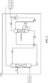
- Fig. 3 is a schematic drawing of an acid gas removal unit of a sulphur recovery facility as modified to be used in an embodiment of the invention; shown is the presence of a hydrolysis reactor on top of an HP absorber.
- Fig. 4 is a schematic drawing of an acid gas removal unit of a sulphur recovery facility as modified to be used in an embodiment of the invention; shown is the presence of a hydrolysis reactor between the bottom of an absorber and an LP regenerator.
- Fig. 5 is a schematic drawing of an acid gas enrichment section of a sulphur recovery facility as modified to be used in an embodiment of the invention, having a hydrolysis reactor between the bottom of an LP absorber and an LP regenerator.
- the main operating conditions preferably employed are:
- Absorption liquid temperature 20°C-150°C
- Absorption liquid concentration of amines 5wt.% - 95 wt% COS conversion in liquid phase via hydrolysis with catalyst: >>50% depending on the type of amine (prior art typically achieves ⁇ 50%)
- Catalyst installation upgrading of conventional equipment (columns, 3 phase separators, heat exchangers, filters, flash vessel, tank) or in a dedicated equipment (reactor).
- a homogeneous catalyst i.e. a metal salt in aqueous solution.
- salts employed are: NH 4 VO 3 (ammonium metavanadate); C 10 H 14 FeO 4 (ferrous acetylacetonate); (C 5 H 8 O 2 ) 3 Ru (ruthenium(III)acetylacetonate); (NH 4 )Mo 7 O 24 ⁇ 4H 2 O (diammonium heptamolybdate tetrahydrate).
Landscapes
- Chemical & Material Sciences (AREA)
- Engineering & Computer Science (AREA)
- Chemical Kinetics & Catalysis (AREA)
- Organic Chemistry (AREA)
- Materials Engineering (AREA)
- Oil, Petroleum & Natural Gas (AREA)
- General Chemical & Material Sciences (AREA)
- Analytical Chemistry (AREA)
- Health & Medical Sciences (AREA)
- Biomedical Technology (AREA)
- Environmental & Geological Engineering (AREA)
- Water Supply & Treatment (AREA)
- Gas Separation By Absorption (AREA)
- Industrial Gases (AREA)
- Treating Waste Gases (AREA)
Description
- The invention pertains to the removal of carbonyl sulphide (COS) from raw natural gas.
- Natural gas typically consists of low hydrocarbons such as methane and some level of acidic impurities. Untreated natural gas is commonly referred to as sour gas. Before being able to use the natural gas, the acidic impurities need to be removed. This is commonly known as sweetening. Typical impurities are CO2, H2S, mercaptans (R-SH), carbonyl sulphide and/or carbon disulphide.
- In the art, gases, other than untreated natural gas, comprising H2S and COS are sometimes also referred to as "sour gas." This concerns, in addition to natural gas, synthesis gas, gas produced by coal gasification, or fumes from a combustion process. In the present description, the term "sour gas" generally indicates a gas comprising H2S and COS, and requiring deacification, and more particularly indicates, preferably, untreated natural gas.
- Known methods for removing acidic impurities employ absorption in amine solutions. However, this method is not suitable for the removal of carbonyl sulphide (O=C=S; mostly known as COS) and carbonyl disulphide (mostly known as CS2). Regulatory changes require a further reduction of all sulfur containing compounds including COS.
- A known method for removing COS and CS2 consists of a two step process, where in a first step, the COS and CS2 is converted into H2S. In a second reactor the H2S is removed. In another method, in a first reactor the COS and CS2 are hydrolyzed and in a second reactor again the H2S is removed. A disadvantage of the latter method is that the absorption liquid does not efficiently absorb H2S,COS and CS2 at the same time. Particularly in the event that relatively high levels of H2S are present (which is typical for sour gas), the removal of COS and CS2 can be insufficient.
- A method that has been proposed to solve this bottleneck, involves the heterogenic, catalytic conversion of contaminants including COS and CS2 into hydrogen sulphide in a separate hydrogenation reactor operating in the gas phase. As a catalyst, typically heavy metals such as iron, lead, molybdenum, nickel, tungsten or sulphide of these metals are employed. A disadvantage of this method is that high operating temperature is needed (200°C-300°C).
-
WO2011/033191 describes a method of this kind. - Therefore, it has been suggested in the alternative to treat gases at such high temperature with basic reacting salts of inorganic or organic bases or any mixtures of them, dissolved in water or alcohol, i.e. with a basic scrubbing medium, so that the contaminants COS and CS2 are changed by means of hydrolysis into hydrogen sulphide according to the equilibrium reactions: (COS + H2O ↔ CO2 + H2S and CS2 + 2H2O ↔ CO2 + 2H2S). The hydrogen sulphide can in turn be removed together with the host gas from the reaction zone. In that practice, the hydrolysis reaction is limited by the equilibrium constant. When the partial pressure of H2S reaches the equilibrium a relatively high level of COS and CS2 remains in the emissions.
- Further, another problem is incurred in the event that a basic absorbing liquid is used. For, the basicity of the absorbing medium has to be maintained in spite of the presence of H2S and CO2. These compounds are to be converted into sulphides and carbonates thus reducing the basicity of the material as a whole. The hydrogen sulphide that is present as well as the hydrogen sulphide that is formed catalytically will then have to be removed from the gas in a separate step.
- Some background art addresses the treatment of gas, other than natural gas, in order to deacidify such gases that contain H2S and COS, or at least remove COS therefrom. E.g.,
WO 00/35806 WO 00/35806 - It is desired to improve the removal of COS from sour gas, preferably from natural gas, particularly untreated natural gas, and more particularly to provide a process that is capable of removing COS more efficiently, yet avoiding the high temperatures required in the art.
- In order to better address one or more of the foregoing desires, the invention presents, in one aspect, a method for removing carbonyl sulphide from an untreated natural gas stream comprising subjecting the gas stream to contact with an absorption liquid so as to provide an absorbed gas-containing liquid, and bringing the absorbed gas-containing liquid in contact with a catalyst suitable for hydrolyzing carbonyl sulphide.
-
-
Fig. 1 is a schematic drawing of a conventional sulphur recovery facility. -
Fig. 2 is a schematic drawing of an acid gas removal unit of a conventional sulphur recovery facility. -
Fig. 3 is a schematic drawing of an acid gas removal unit of a sulphur recovery facility as modified to be used in the method of the invention, having a hydrolysis reactor on top of an HP absorber. -
Fig. 4 is a schematic drawing of an acid gas removal unit of a sulphur recovery facility as modified to be used in the method of the invention, having a hydrolysis reactor between the bottom of an absorber and an LP regenerator. -
Fig. 5 is a schematic drawing of an acid gas enrichment section of a sulphur recovery facility as modified to be used in the method of the invention, having a hydrolysis reactor between the bottom of an LP absorber and an LP regenerator. - In a broad sense, the invention is based on the judicious insight that the removal of COS from a sour gas stream can be conducted more efficiently, and at a relatively low temperature, if one combines the actions of an absorption liquid and catalytic hydrolysis into one and the same medium.
- To this end, the gas stream is subjected to contact with an absorption liquid so as to provide an absorbed gas-containing liquid, and the absorbed gas-containing liquid is contacted with a catalyst suitable for hydrolyzing carbonyl sulphide. It will be understood that the absorbed gas can refer to gas bubbles introduced in the absorption liquid (i.e. a two-phase system having the gas still in the gas phase), to molecularly absorbed compounds (i.e. the gas, components from the gas, or compounds converted from the gas such as H2S being in the liquid phase), or to a combination thereof.
- In one embodiment, the foregoing is realized by subjecting the gas stream to simultaneous contact with the absorption liquid and with the catalyst. Particularly, the method of the invention is thereby conducted in a single reaction vessel. Without wishing to be bound by theory, the present inventors believe that the hydrolysis of COS advantageously affects also the action of the absorption liquid, as it converts COS into compounds that are more easily absorbed. It will be understood that this advantage will be particularly exhibited in the event that the absorbed gas-containing liquid contains the absorbed gas as bubbles (i.e. in the gas phase). For, in that case, the conversion will lead to compounds that are more easily molecularly retained in the absorption liquid, or even absorbed therein molecularly.
- The absorption liquid serves to absorb COS from the gas stream treated. Liquids suitable for this purpose are known to skilled person. These can be based, e.g., on alcohol (methanol) or water. Absorption liquids can be physical solvents or solutions. A preferred absorption liquid is a basic aqueous solution, more preferably an amine solution. Suitable amines include MEA (mono ethanol amine), DEA (diethanol amine), MDEA (methyl diethanol amine), DIPA (diisopropyl amine), DGA (diglycol amine) or special formulated amine solution. Commercial physical solvents, or their mixtures, with or without additives can also be used. The absorption liquid can be a mixture of liquids.
- The catalyst comprises a catalytically active metal, preferably a transition metal or a salt of a transition metal, more preferably selected from the group consisting of vanadium, iron, molybdenum, ruthenium, manganese, chromium, zinc, nickel, combination of them and salts thereof.
- Thereby, typically if in the salt form, the catalyst can be a homogenous catalyst dissolved in the absorption liquid. Preferably, the catalyst is a heterogeneous catalyst, deposited on a suitable support. The latter is of advantage with a view to recovering and regenerating the catalyst particles. Suitable catalysts, and optionally supports, adjuvants and/or promoters, are generally known to the skilled person.
- The present inventors do not particularly aim at providing a novel catalyst for COS hydrolysis. Rather, based on the state of the art in COS catalytic conversion, the invention particularly resides in the novel combination of such a catalytic step into a step of scrubbing with an absorption liquid. The invention also allows to optimize the process scheme configuration, as well as to profit from optimized operating parameters, mainly temperature and residence time.
- In a particularly preferred embodiment, the catalyst is a heterogeneous catalyst presented on an absorption column as used in the absorption step. Thus, the catalyst can, e.g., be deposited on the trays of a column or on the packing of the same. It can be also deposited, in addition to the column or in lieu thereof, in special devices like filtering systems, special packing system outside the column, particularly downstream from where the gas stream is contacted with the absorption liquid.
- Advantageously, in accordance with the invention the carbonyl sulphide is preferably hydrolyzed at a temperature below 150°C, preferably below 130°C.
- In preferred embodiments, the reactor for COS hydrolysis operates at low pressure (generally 0.01 to 0.1 barg, typically about 0.05 barg). This represents an advantage as compared to known COS removal, which typically occurs in a high-pressure absorption step. In fact, this adds to the residence time of the gas in the reactor, which contributes to further lowering the amount of COS in the gas stream. The hydrolytic conversion of COS also helps to overcome the drawbacks associated with the fact that the basicity of the scrubbing liquid (i.e. the amine solution) inevitably becomes reduced during COS absorption.
- The method of the invention can be conducted in a reactor system for removing carbonyl sulphide from a sour gas stream. The reactor system is filled with an absorption liquid (i.e., in particular an absorption liquid is made to pass through the system, preferably involving regeneration and recirculation of the regenerated liquid), and comprises a catalyst suitable for hydrolyzing carbonyl sulphide. In one embodiment, this reactor system comprises a single reaction vessel filled with the absorption liquid, said liquid also comprising the catalyst. In one preferred embodiment, the react or is a column with trays, wherein the catalyst is a heterogeneous catalyst applied as a coating on the trays. In another preferred embodiment, the column is a packed column, wherein the catalyst is coated on the packing. Suitable packing materials are known to the skilled person and include, e.g., stainless steel or ceramic material, such as alumina.
- It is also possible, in embodiments of the reactor system that the catalyst is deposited on one or more available contacting devices other than a column, such as a filtering media, plates designed to separate liquid from gas such as vane packs, corrugated plates, coalescing media, and flashing devices.
- A particular advantage of the invention is represented by the flexibility in the location of the additional step for COS abatement. The first embodiment foresees the use of this reactor on the treated gas stream of an AGR unit (see
Fig. 3 ), i.e. on the top of the absorber (which can be a HP, an MP, or an LP absorber, with HP being preferred. In this embodiment, after the COS hydrolysis reactor, a subsequent stage (not shown) is dedicated to the removal of the produced H2S and thereby reactivating the used absorption liquid, e.g. amine. Thus, in this embodiment, a two stage type of vessel can be employed, if desired a plurality thereof. - The abbreviations used for the various pressure sections referred to in this description have the following meanings:
- LLP stands for very low pressure, typically 0,01-1 barg;
- LP stands for low pressure, typically 1-20 barg;
- MP stands for medium pressure, typically 20-40 barg;
- HP stands for high pressure, typically greater than 40 barg.
- In further preferred embodiments, the COS hydrolysis reactor is positioned either between the bottom of the HP/MP/LP absorber and the LP regenerator, or between the bottom of the LP/LLP absorber and the LP regenerator.
- Thus, with reference to the foregoing embodiments, the method of the invention can be conducted in a sulfur recovery facility comprising
- a. an acid gas removal unit comprising an absorber, operating at high pressure (HP), medium pressure (MP), or low pressure (LP), and an LP regenerator;
- b. an acid gas enrichment/tail gas treatment unit comprising an LP/LLP absorber and an LP regenerator;
- c. a sulfur recovery unit;
- d. a COS hydrolysis reactor;
-
Fig. 1 is a schematic drawing of a conventional sulphur recovery facility. Depicted is (a) a feed stream of sour gas entering into an Acid Gas Removal Unit (AGRU); (b) a stream of treated gas exiting the AGRU; (c) a stream of acid, COS-containing gas fed to a sulphur recovery unit (SRU) via an Acid Gas Enrichment unit (AGE); (d) a resulting stream of enriched acid gas fed to the SRU and rejected CO2 fed to an incinerator; (e) a stream of tail gas from the SRU fed to the incinerator; (f) a stream of recovered sulphur from the SRU. -
Fig. 2 is a schematic drawing of the acid gas removal unit (AGRU) of the above conventional sulphur recovery facility. Shown is how an HP absorber and a regenerator are connected. -
Fig. 3 is a schematic drawing of an acid gas removal unit of a sulphur recovery facility as modified to be used in an embodiment of the invention; shown is the presence of a hydrolysis reactor on top of an HP absorber. -
Fig. 4 is a schematic drawing of an acid gas removal unit of a sulphur recovery facility as modified to be used in an embodiment of the invention; shown is the presence of a hydrolysis reactor between the bottom of an absorber and an LP regenerator. -
Fig. 5 is a schematic drawing of an acid gas enrichment section of a sulphur recovery facility as modified to be used in an embodiment of the invention, having a hydrolysis reactor between the bottom of an LP absorber and an LP regenerator. - The main operating conditions preferably employed are:
- Feedstock: Sour gas (C1, C2, C3, C4, C6+)
- Feedstock temperature: 20°C-80°C
- Feedstock pressure: >0.01 barg
- Type of absorption liquid: MEA, DEA, MDEA, DIPA, DGA, special formulated amine solution, commercial physical solvents, any mixture of them, with or without additive addition.
- Absorption liquid temperature: 20°C-150°C
Absorption liquid concentration of amines: 5wt.% - 95 wt%
COS conversion in liquid phase via hydrolysis with catalyst: >>50% depending on the type of amine (prior art typically achieves <50%) Percentage of deposited catalyst on structured support or any contacting device: <30 wt.%
Catalyst installation: upgrading of conventional equipment (columns, 3 phase separators, heat exchangers, filters, flash vessel, tank) or in a dedicated equipment (reactor). - The invention is hereinafter illustrated with reference to the following nonlimiting Example.
- In this example, a homogeneous catalyst is used, i.e. a metal salt in aqueous solution. Examples of salts employed are: NH4VO3 (ammonium metavanadate); C10H14FeO4 (ferrous acetylacetonate); (C5H8O2)3Ru (ruthenium(III)acetylacetonate); (NH4)Mo7O24 ∗4H2O (diammonium heptamolybdate tetrahydrate).
- P =0.1 barg
Absorption liquid temperature = 25 °C
Absorption liquid concentration, the liquid being an aqueous solution of diethanol amine (DEA) of 15 wt.%
Feedstock COS concentration: 125 ppm - 1000 ppm
Vanadium concentration in the solution: 0.13 M - In the presence of the catalyst, the removal of COS through a hydrolysis reaction is one order of magnitude higher than that obtained in the absence of catalyst.
Claims (10)
- A method for removing carbonyl sulphide from an untreated natural gas stream comprising subjecting the untreated natural gas stream to contact with an absorption liquid so as to provide an absorbed gas-containing liquid, and bringing the absorbed gas-containing liquid in contact with a catalyst suitable for hydrolyzing carbonyl sulphide.
- A method according to claim 1, wherein the gas stream is subjected to simultaneous contact with the absorption liquid and with the catalyst.
- A method according to claim 1 or 2, wherein the contact is brought about in the same vessel.
- A method according to claim 1, wherein the gas stream is subjected to contact with the absorption liquid in an absorption vessel, and wherein the absorbed gas-containing liquid is subjected to contact with the catalyst downstream of said absorption vessel.
- A method according to any one of the preceding claims, wherein the absorption liquid is a basic aqueous solution, preferably an amine solution.
- A method according to any one of the preceding claims, wherein the catalyst is a transition metal or a salt of a transition metal, preferably selected from the group consisting of vanadium, iron, molybdenum, ruthenium, manganese, chromium, zinc, nickel, a combination thereof, and salts thereof.
- A method according to any one of the claims 1 to 6, wherein the catalyst is a heterogeneous catalyst.
- A method according to claim 7, wherein the catalyst, optionally deposited on a mechanical inert support, is dispersed in the solution.
- A method according to claim 7, wherein the catalyst is present in or on an absorption column, preferably applied as a coating on the trays of a column with trays, or coated on the packing of a packed column.
- A method according to any one of the preceding claims, wherein the carbonyl sulphide is hydrolyzed at a temperature of from 20°C to 150°C, preferably 80°C to 130°C.
Priority Applications (1)
| Application Number | Priority Date | Filing Date | Title |
|---|---|---|---|
| EP14714415.8A EP2969131B1 (en) | 2013-03-14 | 2014-03-14 | Cos and cs2 abatement method |
Applications Claiming Priority (3)
| Application Number | Priority Date | Filing Date | Title |
|---|---|---|---|
| EP13159258 | 2013-03-14 | ||
| PCT/NL2014/050157 WO2014142668A2 (en) | 2013-03-14 | 2014-03-14 | Cos and cs2 abatement method |
| EP14714415.8A EP2969131B1 (en) | 2013-03-14 | 2014-03-14 | Cos and cs2 abatement method |
Publications (2)
| Publication Number | Publication Date |
|---|---|
| EP2969131A2 EP2969131A2 (en) | 2016-01-20 |
| EP2969131B1 true EP2969131B1 (en) | 2020-02-26 |
Family
ID=47877923
Family Applications (1)
| Application Number | Title | Priority Date | Filing Date |
|---|---|---|---|
| EP14714415.8A Active EP2969131B1 (en) | 2013-03-14 | 2014-03-14 | Cos and cs2 abatement method |
Country Status (6)
| Country | Link |
|---|---|
| US (3) | US9765272B2 (en) |
| EP (1) | EP2969131B1 (en) |
| CN (2) | CN108467757B (en) |
| DK (1) | DK2969131T3 (en) |
| EA (3) | EA202192874A1 (en) |
| WO (1) | WO2014142668A2 (en) |
Families Citing this family (7)
| Publication number | Priority date | Publication date | Assignee | Title |
|---|---|---|---|---|
| US9884291B2 (en) | 2015-08-06 | 2018-02-06 | Fluor Technologies Corporation | Systems and methods for improved sulfur recovery from claus process tail gas |
| CN106390673A (en) * | 2016-11-30 | 2017-02-15 | 成都丽雅纤维股份有限公司 | System for recovering waste gas in production of viscose |
| CN108993133A (en) * | 2017-06-06 | 2018-12-14 | 中国石油化工股份有限公司 | COS, CS in a kind of promotion natural gas2The method of removing |
| CN110536736A (en) * | 2017-08-25 | 2019-12-03 | 韩国电力公社 | Acid gas capture device |
| CN113308279A (en) * | 2021-05-27 | 2021-08-27 | 北京首钢国际工程技术有限公司 | System and method for desulfurizing metallurgical blast furnace gas |
| CN113549474B (en) * | 2021-08-04 | 2022-08-23 | 上海大学 | Blast furnace gas step-by-step dry deacidification system and method |
| CN115400533B (en) * | 2022-08-23 | 2023-06-30 | 天津绿菱气体有限公司 | Method and device for recycling carbonyl sulfide tail gas |
Family Cites Families (41)
| Publication number | Priority date | Publication date | Assignee | Title |
|---|---|---|---|---|
| US3686712A (en) | 1970-09-29 | 1972-08-29 | Gainesville Machine Co Inc | Shackle suspension means |
| DE2250169A1 (en) | 1972-10-13 | 1974-04-25 | Metallgesellschaft Ag | PROCESS FOR DESULFURIZATION OF TECHNICAL FUEL GASES AND SYNTHESIS GASES |
| US3989811A (en) * | 1975-01-30 | 1976-11-02 | Shell Oil Company | Process for recovering sulfur from fuel gases containing hydrogen sulfide, carbon dioxide, and carbonyl sulfide |
| US4041130A (en) * | 1975-12-29 | 1977-08-09 | The Ralph M. Parsons Company | Process for desulfurization of coke oven gas |
| GB1563251A (en) * | 1976-12-07 | 1980-03-26 | Shell Int Research | Process for working hydrogen suphidecontaining gases |
| DE3015336C2 (en) | 1980-04-22 | 1985-09-19 | Gebr. Stolle GmbH u. Co KG, 2849 Visbek | Method and device for introducing processed offal into gutted slaughter chickens |
| US4409199A (en) * | 1981-12-14 | 1983-10-11 | Shell Oil Company | Removal of H2 S and COS |
| US4482529A (en) * | 1983-01-07 | 1984-11-13 | Air Products And Chemicals, Inc. | Catalytic hydrolysis of COS in acid gas removal solvents |
| US4524050A (en) * | 1983-01-07 | 1985-06-18 | Air Products And Chemicals, Inc. | Catalytic hydrolysis of carbonyl sulfide |
| EP0214407A3 (en) * | 1985-07-15 | 1987-06-24 | Siegfried Prof. Dr. Peter | Process for removing organic sulphur compounds, and/or sulphur oxides and/or nitrogen oxides from gases |
| GB8613314D0 (en) | 1986-06-02 | 1986-07-09 | Era Patents Ltd | Microwave apparatus |
| US5089246A (en) * | 1990-01-29 | 1992-02-18 | Atochem North America, Inc. | Process for converting carbon disulfide to hydrogen sulfide in hydrogen sulfide/carbon disulfide mixtures |
| US5397556A (en) * | 1992-12-16 | 1995-03-14 | The Regents Of The Unviversity Of California | Process for recovery of sulfur from acid gases |
| NL9301871A (en) | 1993-10-29 | 1995-05-16 | Stork Bronswerk B V | Cooling device and method for cooling slaughtered animals. |
| AU4134796A (en) * | 1994-11-03 | 1996-05-31 | Khanmamedov, Tufik K. | Method and apparatus for removal of contaminates from refinery gas |
| WO1998004337A1 (en) | 1996-07-29 | 1998-02-05 | Apollo Environmental Systems Corp. | Natural gas treatment process |
| MY117311A (en) | 1996-08-22 | 2004-06-30 | Shell Int Research | Process for reducing total sulphur content in gases containing hydrogen sulphide and other sulphur components |
| FR2762592B1 (en) | 1997-04-24 | 1999-06-18 | Elf Aquitaine | PROCESS FOR REMOVAL OF SULFUR COMPOUNDS H2S, SO2, COS AND / OR CS2 CONTAINED IN A SULFUR FACTORY RESIDUAL GAS WITH RECOVERY OF SUCH SULFUR COMPOUNDS |
| DE19828977A1 (en) * | 1998-06-29 | 1999-12-30 | Basf Ag | Absorbent for removing acidic components from gases |
| DE19850141A1 (en) * | 1998-10-30 | 2000-05-04 | Basf Ag | Molded body |
| US6322763B1 (en) * | 1998-12-15 | 2001-11-27 | Teco, Inc. | Method and apparatus for removing carbonyl sulfide from a gas stream via wet scrubbing |
| NL1019298C2 (en) | 2001-11-05 | 2003-05-07 | Stork Pmt | Method for preserving meat from a slaughtered bird or part thereof. |
| DE602004014923D1 (en) * | 2003-05-29 | 2008-08-21 | Shell Int Research | PROCESS FOR REMOVING, HCN AND H2S AND WAH |
| US7374742B2 (en) * | 2003-12-19 | 2008-05-20 | Bechtel Group, Inc. | Direct sulfur recovery system |
| US7427385B2 (en) | 2004-12-17 | 2008-09-23 | Exxonmobil Research And Engineering Company | Systems and processes for reducing the sulfur content of hydrocarbon streams |
| AR066680A1 (en) * | 2007-05-25 | 2009-09-02 | Shell Int Research | A PROCESS TO REMOVE SULFUR FROM A FUEL GAS CURRENT, WHICH ALSO CONTAINS CARBON DIOXIDE AND LIGHT OLEFINS |
| US8343445B2 (en) * | 2008-03-21 | 2013-01-01 | Alstom Technology Ltd | System and method for enhanced removal of CO2 from a mixed gas stream |
| AU2012216559A1 (en) * | 2008-03-21 | 2012-09-20 | Alstom Technology Ltd | A system and method for enhanced removal of CO2 from a mixed gas stream |
| US8414853B2 (en) * | 2008-03-21 | 2013-04-09 | Alstom Technology Ltd | System and method for enhanced removal of CO2 from a mixed gas stream via use of a catalyst |
| CN101318099B (en) * | 2008-07-10 | 2012-07-04 | 昆明理工大学 | Process for removing organic sulfur in low-temperature condition |
| NL2002250C2 (en) | 2008-11-25 | 2010-05-26 | Stork Pmt | DEVICE AND METHOD FOR GROWING A LARGE INTENSITY OF DIFFERENT PARTS OF A POULTRY CARCASE. |
| WO2010060970A1 (en) * | 2008-11-28 | 2010-06-03 | Shell Internationale Research Maatschappij B.V. | Process for the selective oxidation of hydrogen sulphide |
| EP2362807B1 (en) | 2008-11-28 | 2015-04-22 | Shell Internationale Research Maatschappij B.V. | A method of treating a syngas stream |
| FR2940920B1 (en) * | 2009-01-12 | 2011-10-21 | Inst Francais Du Petrole | PROCESS FOR REMOVING SULFUR, NITROGEN AND HALOGENATED IMPURITIES CONTAINED IN A SYNTHESIS GAS |
| AU2010233732B2 (en) * | 2009-04-08 | 2013-09-19 | Shell Internationale Research Maatschappij B.V. | Method of treating an acid gas stream and an apparatus therefor |
| JP4395542B1 (en) * | 2009-04-30 | 2010-01-13 | 三菱重工業株式会社 | High purity CO2 recovery method and system from gasification gas |
| FR2950265B1 (en) * | 2009-09-21 | 2012-08-24 | Inst Francais Du Petrole | METHOD FOR DEACIDIFYING GAS BY ABSORBENT SOLUTION WITH COS REMOVAL BY HYDROLYSIS |
| EP2484427B1 (en) * | 2011-02-08 | 2017-07-19 | Neste Oyj | A two-stage gas washing method |
| CN102320577A (en) * | 2011-06-22 | 2012-01-18 | 西南石油大学 | Sulfur recovery technology of direct oxidation by hydration |
| CA2782944C (en) * | 2012-02-17 | 2014-11-04 | Archon Technologies Ltd. | Process for the removal of sulfur compounds from gas streams |
| CN102580473A (en) * | 2012-03-20 | 2012-07-18 | 中国石油化工股份有限公司 | An absorbent for selectively removing H2S and organic sulfur |
-
2014
- 2014-03-14 US US14/773,263 patent/US9765272B2/en active Active
- 2014-03-14 EP EP14714415.8A patent/EP2969131B1/en active Active
- 2014-03-14 WO PCT/NL2014/050157 patent/WO2014142668A2/en not_active Ceased
- 2014-03-14 CN CN201810442639.3A patent/CN108467757B/en active Active
- 2014-03-14 CN CN201480027070.4A patent/CN105228724B/en active Active
- 2014-03-14 EA EA202192874A patent/EA202192874A1/en unknown
- 2014-03-14 EA EA201500928A patent/EA030955B1/en not_active IP Right Cessation
- 2014-03-14 EA EA201890775A patent/EA039354B1/en unknown
- 2014-03-14 DK DK14714415.8T patent/DK2969131T3/en active
-
2017
- 2017-08-15 US US15/677,984 patent/US10865355B2/en active Active
-
2020
- 2020-11-25 US US17/104,644 patent/US11331623B2/en active Active
Non-Patent Citations (1)
| Title |
|---|
| None * |
Also Published As
| Publication number | Publication date |
|---|---|
| CN105228724B (en) | 2018-06-12 |
| CN108467757B (en) | 2021-06-22 |
| US20210079310A1 (en) | 2021-03-18 |
| US20180023012A1 (en) | 2018-01-25 |
| EA201500928A1 (en) | 2016-03-31 |
| WO2014142668A2 (en) | 2014-09-18 |
| US9765272B2 (en) | 2017-09-19 |
| EA202192874A1 (en) | 2022-01-19 |
| US10865355B2 (en) | 2020-12-15 |
| US11331623B2 (en) | 2022-05-17 |
| CN105228724A (en) | 2016-01-06 |
| EP2969131A2 (en) | 2016-01-20 |
| CN108467757A (en) | 2018-08-31 |
| EA030955B1 (en) | 2018-10-31 |
| DK2969131T3 (en) | 2020-03-23 |
| EA201890775A2 (en) | 2018-08-31 |
| WO2014142668A3 (en) | 2014-12-04 |
| EA039354B1 (en) | 2022-01-18 |
| EA201890775A3 (en) | 2019-02-28 |
| US20160017248A1 (en) | 2016-01-21 |
Similar Documents
| Publication | Publication Date | Title |
|---|---|---|
| US11331623B2 (en) | COS and CS2 abatement method | |
| JP6155049B2 (en) | Method for removing mercury in hydrocarbon feedstock with hydrogen recycling | |
| JP5813228B2 (en) | Catalyst composition useful for removing sulfur compounds from gaseous hydrocarbons, process for its production and use thereof | |
| CA1235882A (en) | Process for simultaneously removing nitrogen oxide, sulfur oxide, and particulates | |
| RU2508155C2 (en) | Method and device for decreasing amount of carbon oxysulfide, carbon bisulfide, compounds of metal carbonyls, hydrogen sulphide and hydrocyanic compounds, as well as those of ammonia, arsenic and chlorine in green gas | |
| TWI382873B (en) | Systems and processes for reducing the sulfur content of hydrocarbon streams | |
| Spatolisano et al. | Middle scale hydrogen sulphide conversion and valorisation technologies: a review | |
| EP1890791A1 (en) | Process for the removal of contaminants | |
| EP2784022B1 (en) | Oxygen application in Claus units charged with an additional load -particularly a waste-gas stream containing SO2 and coming from adsorbent regeneration | |
| EP2646407A1 (en) | Sterically hindered amines and associated methods | |
| AU2012370293A1 (en) | Process for the removal of sulfur compounds from gas streams | |
| JPH02245222A (en) | Desulfuration of gas effluent in circulating fulidized bed by reprodusible absorptive material | |
| JP5804747B2 (en) | Method for suppressing metal contamination in syngas production equipment | |
| RU2668925C1 (en) | Method for purifying synthesis gas by scrubbing using aqueous amine solutions | |
| JP5751892B2 (en) | Gas processing method and gas processing apparatus | |
| US9028678B2 (en) | Scrubbing hydrogen sulfide from hydrotreated product | |
| WO2010138281A2 (en) | Process for treating a gas stream or effluent | |
| EA043656B1 (en) | REMOVAL METHOD FOR COS AND CS2 | |
| US8883036B2 (en) | Hydrogen sulfide stream for catalyst sulfidation from refinery rich amines | |
| CN113877405A (en) | Waste lubricating oil hydrogenation gas treatment and discharge process |
Legal Events
| Date | Code | Title | Description |
|---|---|---|---|
| PUAI | Public reference made under article 153(3) epc to a published international application that has entered the european phase |
Free format text: ORIGINAL CODE: 0009012 |
|
| 17P | Request for examination filed |
Effective date: 20150923 |
|
| AK | Designated contracting states |
Kind code of ref document: A2 Designated state(s): AL AT BE BG CH CY CZ DE DK EE ES FI FR GB GR HR HU IE IS IT LI LT LU LV MC MK MT NL NO PL PT RO RS SE SI SK SM TR |
|
| AX | Request for extension of the european patent |
Extension state: BA ME |
|
| DAX | Request for extension of the european patent (deleted) | ||
| STAA | Information on the status of an ep patent application or granted ep patent |
Free format text: STATUS: EXAMINATION IS IN PROGRESS |
|
| 17Q | First examination report despatched |
Effective date: 20170102 |
|
| GRAP | Despatch of communication of intention to grant a patent |
Free format text: ORIGINAL CODE: EPIDOSNIGR1 |
|
| STAA | Information on the status of an ep patent application or granted ep patent |
Free format text: STATUS: GRANT OF PATENT IS INTENDED |
|
| RIC1 | Information provided on ipc code assigned before grant |
Ipc: B01D 53/14 20060101AFI20190906BHEP Ipc: C10L 3/10 20060101ALN20190906BHEP Ipc: B01D 53/48 20060101ALI20190906BHEP |
|
| INTG | Intention to grant announced |
Effective date: 20190926 |
|
| GRAS | Grant fee paid |
Free format text: ORIGINAL CODE: EPIDOSNIGR3 |
|
| GRAA | (expected) grant |
Free format text: ORIGINAL CODE: 0009210 |
|
| STAA | Information on the status of an ep patent application or granted ep patent |
Free format text: STATUS: THE PATENT HAS BEEN GRANTED |
|
| AK | Designated contracting states |
Kind code of ref document: B1 Designated state(s): AL AT BE BG CH CY CZ DE DK EE ES FI FR GB GR HR HU IE IS IT LI LT LU LV MC MK MT NL NO PL PT RO RS SE SI SK SM TR |
|
| REG | Reference to a national code |
Ref country code: GB Ref legal event code: FG4D |
|
| REG | Reference to a national code |
Ref country code: CH Ref legal event code: EP |
|
| REG | Reference to a national code |
Ref country code: AT Ref legal event code: REF Ref document number: 1236957 Country of ref document: AT Kind code of ref document: T Effective date: 20200315 |
|
| REG | Reference to a national code |
Ref country code: IE Ref legal event code: FG4D |
|
| REG | Reference to a national code |
Ref country code: DE Ref legal event code: R096 Ref document number: 602014061475 Country of ref document: DE |
|
| REG | Reference to a national code |
Ref country code: DK Ref legal event code: T3 Effective date: 20200317 |
|
| REG | Reference to a national code |
Ref country code: SE Ref legal event code: TRGR |
|
| PG25 | Lapsed in a contracting state [announced via postgrant information from national office to epo] |
Ref country code: NO Free format text: LAPSE BECAUSE OF FAILURE TO SUBMIT A TRANSLATION OF THE DESCRIPTION OR TO PAY THE FEE WITHIN THE PRESCRIBED TIME-LIMIT Effective date: 20200526 Ref country code: RS Free format text: LAPSE BECAUSE OF FAILURE TO SUBMIT A TRANSLATION OF THE DESCRIPTION OR TO PAY THE FEE WITHIN THE PRESCRIBED TIME-LIMIT Effective date: 20200226 Ref country code: FI Free format text: LAPSE BECAUSE OF FAILURE TO SUBMIT A TRANSLATION OF THE DESCRIPTION OR TO PAY THE FEE WITHIN THE PRESCRIBED TIME-LIMIT Effective date: 20200226 |
|
| REG | Reference to a national code |
Ref country code: NL Ref legal event code: MP Effective date: 20200226 |
|
| REG | Reference to a national code |
Ref country code: LT Ref legal event code: MG4D |
|
| PG25 | Lapsed in a contracting state [announced via postgrant information from national office to epo] |
Ref country code: IS Free format text: LAPSE BECAUSE OF FAILURE TO SUBMIT A TRANSLATION OF THE DESCRIPTION OR TO PAY THE FEE WITHIN THE PRESCRIBED TIME-LIMIT Effective date: 20200626 Ref country code: GR Free format text: LAPSE BECAUSE OF FAILURE TO SUBMIT A TRANSLATION OF THE DESCRIPTION OR TO PAY THE FEE WITHIN THE PRESCRIBED TIME-LIMIT Effective date: 20200527 Ref country code: LV Free format text: LAPSE BECAUSE OF FAILURE TO SUBMIT A TRANSLATION OF THE DESCRIPTION OR TO PAY THE FEE WITHIN THE PRESCRIBED TIME-LIMIT Effective date: 20200226 Ref country code: HR Free format text: LAPSE BECAUSE OF FAILURE TO SUBMIT A TRANSLATION OF THE DESCRIPTION OR TO PAY THE FEE WITHIN THE PRESCRIBED TIME-LIMIT Effective date: 20200226 Ref country code: BG Free format text: LAPSE BECAUSE OF FAILURE TO SUBMIT A TRANSLATION OF THE DESCRIPTION OR TO PAY THE FEE WITHIN THE PRESCRIBED TIME-LIMIT Effective date: 20200526 |
|
| PG25 | Lapsed in a contracting state [announced via postgrant information from national office to epo] |
Ref country code: NL Free format text: LAPSE BECAUSE OF FAILURE TO SUBMIT A TRANSLATION OF THE DESCRIPTION OR TO PAY THE FEE WITHIN THE PRESCRIBED TIME-LIMIT Effective date: 20200226 |
|
| PG25 | Lapsed in a contracting state [announced via postgrant information from national office to epo] |
Ref country code: EE Free format text: LAPSE BECAUSE OF FAILURE TO SUBMIT A TRANSLATION OF THE DESCRIPTION OR TO PAY THE FEE WITHIN THE PRESCRIBED TIME-LIMIT Effective date: 20200226 Ref country code: LT Free format text: LAPSE BECAUSE OF FAILURE TO SUBMIT A TRANSLATION OF THE DESCRIPTION OR TO PAY THE FEE WITHIN THE PRESCRIBED TIME-LIMIT Effective date: 20200226 Ref country code: ES Free format text: LAPSE BECAUSE OF FAILURE TO SUBMIT A TRANSLATION OF THE DESCRIPTION OR TO PAY THE FEE WITHIN THE PRESCRIBED TIME-LIMIT Effective date: 20200226 Ref country code: PT Free format text: LAPSE BECAUSE OF FAILURE TO SUBMIT A TRANSLATION OF THE DESCRIPTION OR TO PAY THE FEE WITHIN THE PRESCRIBED TIME-LIMIT Effective date: 20200719 Ref country code: CZ Free format text: LAPSE BECAUSE OF FAILURE TO SUBMIT A TRANSLATION OF THE DESCRIPTION OR TO PAY THE FEE WITHIN THE PRESCRIBED TIME-LIMIT Effective date: 20200226 Ref country code: RO Free format text: LAPSE BECAUSE OF FAILURE TO SUBMIT A TRANSLATION OF THE DESCRIPTION OR TO PAY THE FEE WITHIN THE PRESCRIBED TIME-LIMIT Effective date: 20200226 Ref country code: SK Free format text: LAPSE BECAUSE OF FAILURE TO SUBMIT A TRANSLATION OF THE DESCRIPTION OR TO PAY THE FEE WITHIN THE PRESCRIBED TIME-LIMIT Effective date: 20200226 Ref country code: SM Free format text: LAPSE BECAUSE OF FAILURE TO SUBMIT A TRANSLATION OF THE DESCRIPTION OR TO PAY THE FEE WITHIN THE PRESCRIBED TIME-LIMIT Effective date: 20200226 |
|
| REG | Reference to a national code |
Ref country code: AT Ref legal event code: MK05 Ref document number: 1236957 Country of ref document: AT Kind code of ref document: T Effective date: 20200226 |
|
| REG | Reference to a national code |
Ref country code: DE Ref legal event code: R097 Ref document number: 602014061475 Country of ref document: DE |
|
| PG25 | Lapsed in a contracting state [announced via postgrant information from national office to epo] |
Ref country code: MC Free format text: LAPSE BECAUSE OF FAILURE TO SUBMIT A TRANSLATION OF THE DESCRIPTION OR TO PAY THE FEE WITHIN THE PRESCRIBED TIME-LIMIT Effective date: 20200226 |
|
| REG | Reference to a national code |
Ref country code: BE Ref legal event code: MM Effective date: 20200331 |
|
| PG25 | Lapsed in a contracting state [announced via postgrant information from national office to epo] |
Ref country code: LU Free format text: LAPSE BECAUSE OF NON-PAYMENT OF DUE FEES Effective date: 20200314 |
|
| PLBE | No opposition filed within time limit |
Free format text: ORIGINAL CODE: 0009261 |
|
| STAA | Information on the status of an ep patent application or granted ep patent |
Free format text: STATUS: NO OPPOSITION FILED WITHIN TIME LIMIT |
|
| PG25 | Lapsed in a contracting state [announced via postgrant information from national office to epo] |
Ref country code: AT Free format text: LAPSE BECAUSE OF FAILURE TO SUBMIT A TRANSLATION OF THE DESCRIPTION OR TO PAY THE FEE WITHIN THE PRESCRIBED TIME-LIMIT Effective date: 20200226 Ref country code: IE Free format text: LAPSE BECAUSE OF NON-PAYMENT OF DUE FEES Effective date: 20200314 |
|
| 26N | No opposition filed |
Effective date: 20201127 |
|
| PG25 | Lapsed in a contracting state [announced via postgrant information from national office to epo] |
Ref country code: SI Free format text: LAPSE BECAUSE OF FAILURE TO SUBMIT A TRANSLATION OF THE DESCRIPTION OR TO PAY THE FEE WITHIN THE PRESCRIBED TIME-LIMIT Effective date: 20200226 Ref country code: BE Free format text: LAPSE BECAUSE OF NON-PAYMENT OF DUE FEES Effective date: 20200331 Ref country code: PL Free format text: LAPSE BECAUSE OF FAILURE TO SUBMIT A TRANSLATION OF THE DESCRIPTION OR TO PAY THE FEE WITHIN THE PRESCRIBED TIME-LIMIT Effective date: 20200226 |
|
| PG25 | Lapsed in a contracting state [announced via postgrant information from national office to epo] |
Ref country code: TR Free format text: LAPSE BECAUSE OF FAILURE TO SUBMIT A TRANSLATION OF THE DESCRIPTION OR TO PAY THE FEE WITHIN THE PRESCRIBED TIME-LIMIT Effective date: 20200226 Ref country code: MT Free format text: LAPSE BECAUSE OF FAILURE TO SUBMIT A TRANSLATION OF THE DESCRIPTION OR TO PAY THE FEE WITHIN THE PRESCRIBED TIME-LIMIT Effective date: 20200226 Ref country code: CY Free format text: LAPSE BECAUSE OF FAILURE TO SUBMIT A TRANSLATION OF THE DESCRIPTION OR TO PAY THE FEE WITHIN THE PRESCRIBED TIME-LIMIT Effective date: 20200226 |
|
| PG25 | Lapsed in a contracting state [announced via postgrant information from national office to epo] |
Ref country code: MK Free format text: LAPSE BECAUSE OF FAILURE TO SUBMIT A TRANSLATION OF THE DESCRIPTION OR TO PAY THE FEE WITHIN THE PRESCRIBED TIME-LIMIT Effective date: 20200226 Ref country code: AL Free format text: LAPSE BECAUSE OF FAILURE TO SUBMIT A TRANSLATION OF THE DESCRIPTION OR TO PAY THE FEE WITHIN THE PRESCRIBED TIME-LIMIT Effective date: 20200226 |
|
| P01 | Opt-out of the competence of the unified patent court (upc) registered |
Effective date: 20230516 |
|
| PGFP | Annual fee paid to national office [announced via postgrant information from national office to epo] |
Ref country code: CH Payment date: 20250401 Year of fee payment: 12 |
|
| REG | Reference to a national code |
Ref country code: CH Ref legal event code: U11 Free format text: ST27 STATUS EVENT CODE: U-0-0-U10-U11 (AS PROVIDED BY THE NATIONAL OFFICE) Effective date: 20260401 |
|
| PGFP | Annual fee paid to national office [announced via postgrant information from national office to epo] |
Ref country code: SE Payment date: 20260319 Year of fee payment: 13 |
|
| PGFP | Annual fee paid to national office [announced via postgrant information from national office to epo] |
Ref country code: GB Payment date: 20260324 Year of fee payment: 13 |
|
| PGFP | Annual fee paid to national office [announced via postgrant information from national office to epo] |
Ref country code: DE Payment date: 20260319 Year of fee payment: 13 Ref country code: DK Payment date: 20260324 Year of fee payment: 13 |
|
| PGFP | Annual fee paid to national office [announced via postgrant information from national office to epo] |
Ref country code: IT Payment date: 20260324 Year of fee payment: 13 |
|
| PGFP | Annual fee paid to national office [announced via postgrant information from national office to epo] |
Ref country code: FR Payment date: 20260320 Year of fee payment: 13 |