EP2968803B1 - Resuscitation device with onboard processor - Google Patents
Resuscitation device with onboard processor Download PDFInfo
- Publication number
- EP2968803B1 EP2968803B1 EP14711093.6A EP14711093A EP2968803B1 EP 2968803 B1 EP2968803 B1 EP 2968803B1 EP 14711093 A EP14711093 A EP 14711093A EP 2968803 B1 EP2968803 B1 EP 2968803B1
- Authority
- EP
- European Patent Office
- Prior art keywords
- resuscitator
- sensor
- information
- processor
- patient
- Prior art date
- Legal status (The legal status is an assumption and is not a legal conclusion. Google has not performed a legal analysis and makes no representation as to the accuracy of the status listed.)
- Not-in-force
Links
Images




Classifications
-
- A—HUMAN NECESSITIES
- A61—MEDICAL OR VETERINARY SCIENCE; HYGIENE
- A61M—DEVICES FOR INTRODUCING MEDIA INTO, OR ONTO, THE BODY; DEVICES FOR TRANSDUCING BODY MEDIA OR FOR TAKING MEDIA FROM THE BODY; DEVICES FOR PRODUCING OR ENDING SLEEP OR STUPOR
- A61M16/00—Devices for influencing the respiratory system of patients by gas treatment, e.g. ventilators; Tracheal tubes
- A61M16/0057—Pumps therefor
- A61M16/0078—Breathing bags
-
- A—HUMAN NECESSITIES
- A61—MEDICAL OR VETERINARY SCIENCE; HYGIENE
- A61B—DIAGNOSIS; SURGERY; IDENTIFICATION
- A61B5/00—Measuring for diagnostic purposes; Identification of persons
- A61B5/0002—Remote monitoring of patients using telemetry, e.g. transmission of vital signals via a communication network
- A61B5/0015—Remote monitoring of patients using telemetry, e.g. transmission of vital signals via a communication network characterised by features of the telemetry system
- A61B5/0022—Monitoring a patient using a global network, e.g. telephone networks, internet
-
- A—HUMAN NECESSITIES
- A61—MEDICAL OR VETERINARY SCIENCE; HYGIENE
- A61B—DIAGNOSIS; SURGERY; IDENTIFICATION
- A61B5/00—Measuring for diagnostic purposes; Identification of persons
- A61B5/01—Measuring temperature of body parts ; Diagnostic temperature sensing, e.g. for malignant or inflamed tissue
-
- A—HUMAN NECESSITIES
- A61—MEDICAL OR VETERINARY SCIENCE; HYGIENE
- A61B—DIAGNOSIS; SURGERY; IDENTIFICATION
- A61B5/00—Measuring for diagnostic purposes; Identification of persons
- A61B5/08—Measuring devices for evaluating the respiratory organs
- A61B5/0816—Measuring devices for examining respiratory frequency
-
- A—HUMAN NECESSITIES
- A61—MEDICAL OR VETERINARY SCIENCE; HYGIENE
- A61B—DIAGNOSIS; SURGERY; IDENTIFICATION
- A61B5/00—Measuring for diagnostic purposes; Identification of persons
- A61B5/08—Measuring devices for evaluating the respiratory organs
- A61B5/082—Evaluation by breath analysis, e.g. determination of the chemical composition of exhaled breath
-
- A—HUMAN NECESSITIES
- A61—MEDICAL OR VETERINARY SCIENCE; HYGIENE
- A61B—DIAGNOSIS; SURGERY; IDENTIFICATION
- A61B5/00—Measuring for diagnostic purposes; Identification of persons
- A61B5/08—Measuring devices for evaluating the respiratory organs
- A61B5/087—Measuring breath flow
- A61B5/0876—Measuring breath flow using means deflected by the fluid stream, e.g. flaps
-
- A—HUMAN NECESSITIES
- A61—MEDICAL OR VETERINARY SCIENCE; HYGIENE
- A61B—DIAGNOSIS; SURGERY; IDENTIFICATION
- A61B5/00—Measuring for diagnostic purposes; Identification of persons
- A61B5/08—Measuring devices for evaluating the respiratory organs
- A61B5/091—Measuring volume of inspired or expired gases, e.g. to determine lung capacity
-
- A—HUMAN NECESSITIES
- A61—MEDICAL OR VETERINARY SCIENCE; HYGIENE
- A61B—DIAGNOSIS; SURGERY; IDENTIFICATION
- A61B5/00—Measuring for diagnostic purposes; Identification of persons
- A61B5/48—Other medical applications
- A61B5/4836—Diagnosis combined with treatment in closed-loop systems or methods
-
- A—HUMAN NECESSITIES
- A61—MEDICAL OR VETERINARY SCIENCE; HYGIENE
- A61B—DIAGNOSIS; SURGERY; IDENTIFICATION
- A61B5/00—Measuring for diagnostic purposes; Identification of persons
- A61B5/74—Details of notification to user or communication with user or patient; User input means
- A61B5/742—Details of notification to user or communication with user or patient; User input means using visual displays
-
- A—HUMAN NECESSITIES
- A61—MEDICAL OR VETERINARY SCIENCE; HYGIENE
- A61M—DEVICES FOR INTRODUCING MEDIA INTO, OR ONTO, THE BODY; DEVICES FOR TRANSDUCING BODY MEDIA OR FOR TAKING MEDIA FROM THE BODY; DEVICES FOR PRODUCING OR ENDING SLEEP OR STUPOR
- A61M16/00—Devices for influencing the respiratory system of patients by gas treatment, e.g. ventilators; Tracheal tubes
- A61M16/0051—Devices for influencing the respiratory system of patients by gas treatment, e.g. ventilators; Tracheal tubes with alarm devices
-
- A—HUMAN NECESSITIES
- A61—MEDICAL OR VETERINARY SCIENCE; HYGIENE
- A61M—DEVICES FOR INTRODUCING MEDIA INTO, OR ONTO, THE BODY; DEVICES FOR TRANSDUCING BODY MEDIA OR FOR TAKING MEDIA FROM THE BODY; DEVICES FOR PRODUCING OR ENDING SLEEP OR STUPOR
- A61M16/00—Devices for influencing the respiratory system of patients by gas treatment, e.g. ventilators; Tracheal tubes
- A61M16/0057—Pumps therefor
- A61M16/0084—Pumps therefor self-reinflatable by elasticity, e.g. resuscitation squeeze bags
-
- A—HUMAN NECESSITIES
- A61—MEDICAL OR VETERINARY SCIENCE; HYGIENE
- A61M—DEVICES FOR INTRODUCING MEDIA INTO, OR ONTO, THE BODY; DEVICES FOR TRANSDUCING BODY MEDIA OR FOR TAKING MEDIA FROM THE BODY; DEVICES FOR PRODUCING OR ENDING SLEEP OR STUPOR
- A61M16/00—Devices for influencing the respiratory system of patients by gas treatment, e.g. ventilators; Tracheal tubes
- A61M16/021—Devices for influencing the respiratory system of patients by gas treatment, e.g. ventilators; Tracheal tubes operated by electrical means
- A61M16/022—Control means therefor
- A61M16/024—Control means therefor including calculation means, e.g. using a processor
-
- A—HUMAN NECESSITIES
- A61—MEDICAL OR VETERINARY SCIENCE; HYGIENE
- A61M—DEVICES FOR INTRODUCING MEDIA INTO, OR ONTO, THE BODY; DEVICES FOR TRANSDUCING BODY MEDIA OR FOR TAKING MEDIA FROM THE BODY; DEVICES FOR PRODUCING OR ENDING SLEEP OR STUPOR
- A61M16/00—Devices for influencing the respiratory system of patients by gas treatment, e.g. ventilators; Tracheal tubes
- A61M16/04—Tracheal tubes
-
- A—HUMAN NECESSITIES
- A61—MEDICAL OR VETERINARY SCIENCE; HYGIENE
- A61M—DEVICES FOR INTRODUCING MEDIA INTO, OR ONTO, THE BODY; DEVICES FOR TRANSDUCING BODY MEDIA OR FOR TAKING MEDIA FROM THE BODY; DEVICES FOR PRODUCING OR ENDING SLEEP OR STUPOR
- A61M16/00—Devices for influencing the respiratory system of patients by gas treatment, e.g. ventilators; Tracheal tubes
- A61M16/06—Respiratory or anaesthetic masks
-
- A—HUMAN NECESSITIES
- A61—MEDICAL OR VETERINARY SCIENCE; HYGIENE
- A61M—DEVICES FOR INTRODUCING MEDIA INTO, OR ONTO, THE BODY; DEVICES FOR TRANSDUCING BODY MEDIA OR FOR TAKING MEDIA FROM THE BODY; DEVICES FOR PRODUCING OR ENDING SLEEP OR STUPOR
- A61M16/00—Devices for influencing the respiratory system of patients by gas treatment, e.g. ventilators; Tracheal tubes
- A61M16/20—Valves specially adapted to medical respiratory devices
- A61M16/208—Non-controlled one-way valves, e.g. exhalation, check, pop-off non-rebreathing valves
-
- A—HUMAN NECESSITIES
- A61—MEDICAL OR VETERINARY SCIENCE; HYGIENE
- A61B—DIAGNOSIS; SURGERY; IDENTIFICATION
- A61B5/00—Measuring for diagnostic purposes; Identification of persons
- A61B5/0002—Remote monitoring of patients using telemetry, e.g. transmission of vital signals via a communication network
-
- A—HUMAN NECESSITIES
- A61—MEDICAL OR VETERINARY SCIENCE; HYGIENE
- A61B—DIAGNOSIS; SURGERY; IDENTIFICATION
- A61B5/00—Measuring for diagnostic purposes; Identification of persons
- A61B5/74—Details of notification to user or communication with user or patient; User input means
-
- A—HUMAN NECESSITIES
- A61—MEDICAL OR VETERINARY SCIENCE; HYGIENE
- A61M—DEVICES FOR INTRODUCING MEDIA INTO, OR ONTO, THE BODY; DEVICES FOR TRANSDUCING BODY MEDIA OR FOR TAKING MEDIA FROM THE BODY; DEVICES FOR PRODUCING OR ENDING SLEEP OR STUPOR
- A61M16/00—Devices for influencing the respiratory system of patients by gas treatment, e.g. ventilators; Tracheal tubes
- A61M16/0003—Accessories therefor, e.g. sensors, vibrators, negative pressure
- A61M2016/0015—Accessories therefor, e.g. sensors, vibrators, negative pressure inhalation detectors
- A61M2016/0018—Accessories therefor, e.g. sensors, vibrators, negative pressure inhalation detectors electrical
- A61M2016/0021—Accessories therefor, e.g. sensors, vibrators, negative pressure inhalation detectors electrical with a proportional output signal, e.g. from a thermistor
-
- A—HUMAN NECESSITIES
- A61—MEDICAL OR VETERINARY SCIENCE; HYGIENE
- A61M—DEVICES FOR INTRODUCING MEDIA INTO, OR ONTO, THE BODY; DEVICES FOR TRANSDUCING BODY MEDIA OR FOR TAKING MEDIA FROM THE BODY; DEVICES FOR PRODUCING OR ENDING SLEEP OR STUPOR
- A61M16/00—Devices for influencing the respiratory system of patients by gas treatment, e.g. ventilators; Tracheal tubes
- A61M16/0003—Accessories therefor, e.g. sensors, vibrators, negative pressure
- A61M2016/0027—Accessories therefor, e.g. sensors, vibrators, negative pressure pressure meter
-
- A—HUMAN NECESSITIES
- A61—MEDICAL OR VETERINARY SCIENCE; HYGIENE
- A61M—DEVICES FOR INTRODUCING MEDIA INTO, OR ONTO, THE BODY; DEVICES FOR TRANSDUCING BODY MEDIA OR FOR TAKING MEDIA FROM THE BODY; DEVICES FOR PRODUCING OR ENDING SLEEP OR STUPOR
- A61M16/00—Devices for influencing the respiratory system of patients by gas treatment, e.g. ventilators; Tracheal tubes
- A61M16/0003—Accessories therefor, e.g. sensors, vibrators, negative pressure
- A61M2016/003—Accessories therefor, e.g. sensors, vibrators, negative pressure with a flowmeter
- A61M2016/0033—Accessories therefor, e.g. sensors, vibrators, negative pressure with a flowmeter electrical
-
- A—HUMAN NECESSITIES
- A61—MEDICAL OR VETERINARY SCIENCE; HYGIENE
- A61M—DEVICES FOR INTRODUCING MEDIA INTO, OR ONTO, THE BODY; DEVICES FOR TRANSDUCING BODY MEDIA OR FOR TAKING MEDIA FROM THE BODY; DEVICES FOR PRODUCING OR ENDING SLEEP OR STUPOR
- A61M2202/00—Special media to be introduced, removed or treated
- A61M2202/02—Gases
- A61M2202/0208—Oxygen
-
- A—HUMAN NECESSITIES
- A61—MEDICAL OR VETERINARY SCIENCE; HYGIENE
- A61M—DEVICES FOR INTRODUCING MEDIA INTO, OR ONTO, THE BODY; DEVICES FOR TRANSDUCING BODY MEDIA OR FOR TAKING MEDIA FROM THE BODY; DEVICES FOR PRODUCING OR ENDING SLEEP OR STUPOR
- A61M2205/00—General characteristics of the apparatus
- A61M2205/33—Controlling, regulating or measuring
- A61M2205/3303—Using a biosensor
-
- A—HUMAN NECESSITIES
- A61—MEDICAL OR VETERINARY SCIENCE; HYGIENE
- A61M—DEVICES FOR INTRODUCING MEDIA INTO, OR ONTO, THE BODY; DEVICES FOR TRANSDUCING BODY MEDIA OR FOR TAKING MEDIA FROM THE BODY; DEVICES FOR PRODUCING OR ENDING SLEEP OR STUPOR
- A61M2205/00—General characteristics of the apparatus
- A61M2205/33—Controlling, regulating or measuring
- A61M2205/3324—PH measuring means
-
- A—HUMAN NECESSITIES
- A61—MEDICAL OR VETERINARY SCIENCE; HYGIENE
- A61M—DEVICES FOR INTRODUCING MEDIA INTO, OR ONTO, THE BODY; DEVICES FOR TRANSDUCING BODY MEDIA OR FOR TAKING MEDIA FROM THE BODY; DEVICES FOR PRODUCING OR ENDING SLEEP OR STUPOR
- A61M2205/00—General characteristics of the apparatus
- A61M2205/33—Controlling, regulating or measuring
- A61M2205/3368—Temperature
-
- A—HUMAN NECESSITIES
- A61—MEDICAL OR VETERINARY SCIENCE; HYGIENE
- A61M—DEVICES FOR INTRODUCING MEDIA INTO, OR ONTO, THE BODY; DEVICES FOR TRANSDUCING BODY MEDIA OR FOR TAKING MEDIA FROM THE BODY; DEVICES FOR PRODUCING OR ENDING SLEEP OR STUPOR
- A61M2205/00—General characteristics of the apparatus
- A61M2205/35—Communication
- A61M2205/3576—Communication with non implanted data transmission devices, e.g. using external transmitter or receiver
- A61M2205/3584—Communication with non implanted data transmission devices, e.g. using external transmitter or receiver using modem, internet or Bluetooth®
-
- A—HUMAN NECESSITIES
- A61—MEDICAL OR VETERINARY SCIENCE; HYGIENE
- A61M—DEVICES FOR INTRODUCING MEDIA INTO, OR ONTO, THE BODY; DEVICES FOR TRANSDUCING BODY MEDIA OR FOR TAKING MEDIA FROM THE BODY; DEVICES FOR PRODUCING OR ENDING SLEEP OR STUPOR
- A61M2205/00—General characteristics of the apparatus
- A61M2205/35—Communication
- A61M2205/3576—Communication with non implanted data transmission devices, e.g. using external transmitter or receiver
- A61M2205/3592—Communication with non implanted data transmission devices, e.g. using external transmitter or receiver using telemetric means, e.g. radio or optical transmission
-
- A—HUMAN NECESSITIES
- A61—MEDICAL OR VETERINARY SCIENCE; HYGIENE
- A61M—DEVICES FOR INTRODUCING MEDIA INTO, OR ONTO, THE BODY; DEVICES FOR TRANSDUCING BODY MEDIA OR FOR TAKING MEDIA FROM THE BODY; DEVICES FOR PRODUCING OR ENDING SLEEP OR STUPOR
- A61M2205/00—General characteristics of the apparatus
- A61M2205/50—General characteristics of the apparatus with microprocessors or computers
-
- A—HUMAN NECESSITIES
- A61—MEDICAL OR VETERINARY SCIENCE; HYGIENE
- A61M—DEVICES FOR INTRODUCING MEDIA INTO, OR ONTO, THE BODY; DEVICES FOR TRANSDUCING BODY MEDIA OR FOR TAKING MEDIA FROM THE BODY; DEVICES FOR PRODUCING OR ENDING SLEEP OR STUPOR
- A61M2205/00—General characteristics of the apparatus
- A61M2205/50—General characteristics of the apparatus with microprocessors or computers
- A61M2205/502—User interfaces, e.g. screens or keyboards
-
- A—HUMAN NECESSITIES
- A61—MEDICAL OR VETERINARY SCIENCE; HYGIENE
- A61M—DEVICES FOR INTRODUCING MEDIA INTO, OR ONTO, THE BODY; DEVICES FOR TRANSDUCING BODY MEDIA OR FOR TAKING MEDIA FROM THE BODY; DEVICES FOR PRODUCING OR ENDING SLEEP OR STUPOR
- A61M2205/00—General characteristics of the apparatus
- A61M2205/50—General characteristics of the apparatus with microprocessors or computers
- A61M2205/502—User interfaces, e.g. screens or keyboards
- A61M2205/505—Touch-screens; Virtual keyboard or keypads; Virtual buttons; Soft keys; Mouse touches
-
- A—HUMAN NECESSITIES
- A61—MEDICAL OR VETERINARY SCIENCE; HYGIENE
- A61M—DEVICES FOR INTRODUCING MEDIA INTO, OR ONTO, THE BODY; DEVICES FOR TRANSDUCING BODY MEDIA OR FOR TAKING MEDIA FROM THE BODY; DEVICES FOR PRODUCING OR ENDING SLEEP OR STUPOR
- A61M2205/00—General characteristics of the apparatus
- A61M2205/50—General characteristics of the apparatus with microprocessors or computers
- A61M2205/52—General characteristics of the apparatus with microprocessors or computers with memories providing a history of measured variating parameters of apparatus or patient
-
- A—HUMAN NECESSITIES
- A61—MEDICAL OR VETERINARY SCIENCE; HYGIENE
- A61M—DEVICES FOR INTRODUCING MEDIA INTO, OR ONTO, THE BODY; DEVICES FOR TRANSDUCING BODY MEDIA OR FOR TAKING MEDIA FROM THE BODY; DEVICES FOR PRODUCING OR ENDING SLEEP OR STUPOR
- A61M2205/00—General characteristics of the apparatus
- A61M2205/58—Means for facilitating use, e.g. by people with impaired vision
- A61M2205/581—Means for facilitating use, e.g. by people with impaired vision by audible feedback
-
- A—HUMAN NECESSITIES
- A61—MEDICAL OR VETERINARY SCIENCE; HYGIENE
- A61M—DEVICES FOR INTRODUCING MEDIA INTO, OR ONTO, THE BODY; DEVICES FOR TRANSDUCING BODY MEDIA OR FOR TAKING MEDIA FROM THE BODY; DEVICES FOR PRODUCING OR ENDING SLEEP OR STUPOR
- A61M2205/00—General characteristics of the apparatus
- A61M2205/58—Means for facilitating use, e.g. by people with impaired vision
- A61M2205/583—Means for facilitating use, e.g. by people with impaired vision by visual feedback
-
- A—HUMAN NECESSITIES
- A61—MEDICAL OR VETERINARY SCIENCE; HYGIENE
- A61M—DEVICES FOR INTRODUCING MEDIA INTO, OR ONTO, THE BODY; DEVICES FOR TRANSDUCING BODY MEDIA OR FOR TAKING MEDIA FROM THE BODY; DEVICES FOR PRODUCING OR ENDING SLEEP OR STUPOR
- A61M2205/00—General characteristics of the apparatus
- A61M2205/82—Internal energy supply devices
- A61M2205/8206—Internal energy supply devices battery-operated
- A61M2205/8212—Internal energy supply devices battery-operated with means or measures taken for minimising energy consumption
-
- A—HUMAN NECESSITIES
- A61—MEDICAL OR VETERINARY SCIENCE; HYGIENE
- A61M—DEVICES FOR INTRODUCING MEDIA INTO, OR ONTO, THE BODY; DEVICES FOR TRANSDUCING BODY MEDIA OR FOR TAKING MEDIA FROM THE BODY; DEVICES FOR PRODUCING OR ENDING SLEEP OR STUPOR
- A61M2230/00—Measuring parameters of the user
- A61M2230/40—Respiratory characteristics
- A61M2230/42—Rate
-
- A—HUMAN NECESSITIES
- A61—MEDICAL OR VETERINARY SCIENCE; HYGIENE
- A61M—DEVICES FOR INTRODUCING MEDIA INTO, OR ONTO, THE BODY; DEVICES FOR TRANSDUCING BODY MEDIA OR FOR TAKING MEDIA FROM THE BODY; DEVICES FOR PRODUCING OR ENDING SLEEP OR STUPOR
- A61M2230/00—Measuring parameters of the user
- A61M2230/40—Respiratory characteristics
- A61M2230/43—Composition of exhalation
- A61M2230/432—Composition of exhalation partial CO2 pressure (P-CO2)
Definitions
- the present disclosure generally relates to manual resuscitation devices and, in particular, a resuscitator that incorporates electronic sensing and processing.
- a resuscitator sometimes referred to as a bag valve mask (BVM) or by the proprietary name "Ambu bag,” is a hand-held device used to provide positive pressure ventilation to a patient who is not breathing or who is breathing inadequately.
- the resuscitator is a normal part of a "crash cart” used within a hospital or a resuscitation kit provided to ambulance crew.
- a resuscitator may also be used in an operating room to ventilate an anaesthetized patient prior to attachment of a mechanical ventilator.
- a resuscitator may be self-filling with air or provided with a source of breathing gas, such as oxygen, to increase the oxygenation of the patient.
- US 2002/117173 describes a resuscitation system for resuscitation of asthma patients including a deflatable bag and a gas flow channel connected with said bag.
- US 2008/214948 describes a device for monitoring respiration comprising a duct containing a pressure sensor.
- US 2007/261698 describes a patient vital sign monitoring device.
- US 2012302910 describes a wireless ventilator reporting system.
- FIG. 1 depicts a conventional resuscitator 10 that is connected to a line 20 that provides oxygen or other breathing gas.
- a bag 14 is connected to a mask 12 by a flow channel 16 that also has a valve assembly 1 8 that prevents backflow into the bag 14 and diverts exhaled gas to the atmosphere.
- An accumulator bag 22 is connected at the junction of the bag 14 and line 20 to accumulate a reservoir of oxygen such that the self-expansion of the bag 14 is not limited by the flow rate of line 20.
- FIG. 2 depicts another conventional resuscitator 30 having a mechanical pressure gauge 32 connected to the flow channel 16.
- the gauge 32 is marked with a green zone to indicate the desirable range of inflation pressure as well as yellow and red zones to indicate zones of excess inflation pressures.
- These types of mechanical gauges have limited resolution and reading such a gauge can be a challenge for caregivers as the gauge provides only an instantaneous reading and the caregiver cannot pay constant attention to the gauge as they may be performing other actions, for example striving to maintain a proper seal of the mask to the patient's face and mon itoring other symptoms and aspects of the patient's condition.
- US Patent Publication 2002/117173 describes a resuscitation system including a deflatable bag and a gas flow channel connected with said bag and an indicator for detecting expiration flow and/or pressure within at least one of a flow channel and exhalation port associated with the bag to detect inadequacy in the expiratory component of ventilation during CPR.
- German Patent Publication 10132 269 describes a pressure sensor having s a base body and a circular disk shaped membrane that is connected to the base body around its outer edge
- US Patent 5155653 describes a capacitive pressure sensor including a diaphragm positioned within a pressure chamber with a central portion of the diaphragm positioned in the pressure chamber and an annular peripheral portion of the diaphragm positioned in a measurement chamber.
- none of these teaches a method of measuring a parameter in a resuscitator by measuring contacts between a flexible disc and a porous plate to which it is coupled.
- the resuscitator disclosed herein provides automatic monitoring of various aspects of the operation of the resuscitator as well as the patient's breathing and exhaled breath.
- the information gathered by the resuscitator can be provided in real time to the caregiver to aid in their resuscitation efforts or stored for later review and analysis.
- the invention is defined by the appended claim 1.
- a resuscitator includes a patient airway interface device, a bag, a flow passage coupled between the bag and patient airway interface device, and a sensor assembly.
- the sensor assembly may have a display, at least one sensor coupled to the flow passage and configured to provide a measurement of at least one parameter, and a processor coupled to the display and the at least one sensor.
- the processor may be configured to receive the measurement from the at least one sensor and provide information on the display based on the received measurement.
- a resuscitator in certain embodiments, includes a patient airway interface device, a bag, a flow passage coupled between the bag and patient airway interface device, and a sensor assembly having an indicator, at least one sensor coupled to the flow passage and configured to provide a measurement of at least one parameter, and a processor coupled to the indicator and the at least one sensor.
- the processor is configured to receive the measurement from the at least one sensor and actuate the indicator based on the received measurement.
- a method includes the steps of measuring at least one of a flow rate, a pressure, a temperature, a pH, and a chemical marker in the exhaled breath of a patient; and actuating an indicator so as to provide information related to at least one of a breath rate, a tidal volume, a pressure-vs-time curve, a presence of a chemical in the patient's breath, or a condition of the patient.
- the resuscitator disclosed herein provides automatic monitoring of various aspects of the operation of the resuscitator as well as the patient's breathing and exhaled breath.
- the information gathered by the resuscitator can be provided in real-time to the caregiver to aid in their resuscitation efforts or stored for later review and analysis.
- the disclosed resuscitator may include sensors that continuously or intermittently measure the pressure within the patient airway interface device and, during an exhalation by the patient, may measure one or more of chemical markers or particular chemicals, temperature, or pH.
- the resuscitator may also provide guidance to the caregiver such as a metronome of the optimal rate of inhalations, visual or audible alarms, and verbal communication.
- This disclosure describes embodiments that include a mask intended to placed over a patient's nose and/or mouth so as to form a sealed connection to the patient's airway. It should be understood that other types of patient airway interfaces may be used in place of the mask, for example an endotracheal tube, without departing from the scope of this disclosure. In general, the term "mask" includes all types of patient airway interface devices.
- FIG. 1 depicts a conventional resuscitator 10.
- a flexible mask 12 is configured to be placed over a patient's mouth and nose.
- the bag 14 is connected to the mask 12 by a flow channel 16.
- a valve assembly 18 is attached to the flow channel 16 and includes a valve (not visible in FIG. 1 ) that prevents an exhaled breath from entering the bag 14 and diverts the exhaled breath out a port to the ambient atmosphere.
- This resuscitator 10 may be attached to a line 20 that provides oxygen, or other breathing gas, with an accumulator bag 22 connected at the junction of the bag 14 and line 20 to accumulate a reservoir of oxygen such that the self-expansion of the bag 14 is not limited by the flow rate of line 20.
- FIG. 2 depicts another conventional resuscitator 30 having a mechanical pressure gauge 32 connected to the flow channel 16.
- the gauge 32 is marked with a green zone 32A to indicate the desirable range of inflation pressure as well as a yellow zone 32B and a red zone 32C to indicate zones of excess inflation pressures.
- the mechanical inertia of the gauge 32 may delay or dampen the displayed value compared to the true instantaneous pressure in the flow channel 16.
- FIG. 3 is a schematic representation of an exemplary resuscitator 100 according to certain aspects of the present disclosure.
- the resuscitator 100 includes a bag 110 connected to a mask 112 through a flow passage 114.
- the bag 110 is manually squeezed to force air or other breathing gas into the patient's lungs, after which the bag 110 self-expands to draw in new air or gas.
- a valve assembly 116 containing a shutter valve (not visible in FIG. 3 ) or equivalent, is attached to the flow passage 114 to divert exhaled gas to the atmosphere.
- a sensor module 120 that includes a display 132 is coupled, in this example, to the flow passage 114 between the mask 112 and the valve assembly 116.
- the sensor assembly 120 is operatively coupled to the valve assembly 116.
- the sensor assembly 120 is discussed in greater detail with respect to FIG. 4 .
- the mask 112 may be replaced by other types of breathing interface devices, for example an endotracheal tube or laryngeal mask airway (not shown in FIG. 3 ).
- the bag 110 draws in a breathing gas, for example oxygen, through an attached line 118.
- a reservoir (not shown in FIG. 3 ) may be attached proximate to the junction of the line 118 and bag 110 to provide a large volume of the breathing gas such that the self-expansion of the bag 110 is not limited by the flow rate of line 118.
- FIG. 4 is a block diagram of the example sensor module 120 that is part of the resuscitator 100 of FIG. 3 according to certain aspects of the present disclosure.
- the sensor module 120 may include one or more of a processor 122, a timer 124, a pressure sensor 126, a chemical sensor 128, a communication (comm) module 130, a display 132, an alarm 134, a temperature sensor 136, and a pH sensor 138 that are interconnected by a network 142.
- Other elements common to electronic equipment, for example batteries or power supplies, touch screen interfaces, buttons, switches, and connectors, that are known to those of skill in the art are omitted so as not to obscure the disclosed features.
- the processor 122 is discussed in greater detail with respect to FIG. 5 .
- the flow sensor 200 is discussed in greater detail with respect to FIG. 6 .
- the pressure sensor 126 may be any device or mechanism configured to measure a gas pressure as are known to those of skill in the art.
- the pressure sensor 126, as well as one or more of the other sensors 128, 136, 138, and 200, may include resistive, capacitive, piezoelectric, or solid state electronic devices with or without embedded signal-conditioning circuitry.
- the pressure sensor 126, or other sensor may be configured to detect an initial manual compression of the resuscitator bag 110 and trigger certain functions, for example turning on the display 132 and powering up other elements of the sensor module 120.
- the pressure sensor 126 or other sensor may be configured to detect inactivity over a determined period of time and trigger other functions, for example turning off the display 132 and placing the CPU in a low-power state to conserve power.
- the chemical sensor 128 may include one or more sensors that may be configured to detect in the patient's exhaled breath the presence or amount of certain chemical markers associated with certain physical attributes. In certain embodiments, the chemical sensor 128 may detect or measure markers associated with a level of alcohol or a drug in the patient's blood. In certain embodiments, the chemical sensor 128 may detect or measure a peroxide level in the patient's breath that may be associated with asthma. In certain embodiments, the chemical sensor 128 may measure one or more partial pressures of certain gases, for example carbon dioxide, in the patient's exhaled breath.
- the comm module 130 may include a wireless communication system, for example using Bluetooth® (IEEE 802.15.1) or Wi-Fi (IEEE 802.11) elements and protocols, that allows the sensor module 120 to communicate with external equipment.
- the comm module 130 may include a port for connection of a communication cable, for example a CAT5 cable, to enable communication with external equipment.
- the comm module 130 may include a port for a removable media, for example a USB port to connect to a "thumb drive," or a drive configured to read and/or write to a removable media, for example a CD or DVD.
- the display 132 may be any audio or visual device as known to those of skill in the art.
- the display 132 may include a color or monochrome two-dimensional visual display that may include one or more of light emitting diodes (LEDs), liquid crystals, "electronic paper” such as electrophoretic display technologies, or electroluminescent elements.
- the display 132 may be an audio device (132b in FIG. 3 ) such as a speaker, buzzer, or tone generator.
- the display 132 may be a visual indicator (132a in FIG. 3 ) such as a single monochrome LED, a group of LEDs of various colors, an incandescent bulb, or a linear array of single light-emitting elements.
- the alarm 134 may include visual indicators, for example lights that may be selectably illuminated, or audible indicators, for example a speaker, a tone generator, or a buzzer.
- the alarm 134 may be a visual element provided on the display 132.
- a visual or audible signal may be provided continuously or during non-alarm conditions. For example, a tone of a first frequency or combination of frequencies may be provided when the caregiver is operating the resuscitator within the desired range of pressure.
- the visual or audible signal may change, for example to a tone of a second frequency or combination of frequencies, when the pressure exceeds the desired range.
- the resuscitator 100 may have a disposable portion, for example the bag 110, flow passage 114, and mask 112, to which a re-useable portion, for example the sensor module 120, is attached.
- the disposable portion may include a sensor, for example a flow sensor such as shown in FIG. 6 , that functionally connects to the processor 122.
- the entire resuscitator 100 may be disposable.
- FIG. 5 is a block diagram of the example processor 122 that is part of the sensor module 120 of FIG. 4 according to certain aspects of the present disclosure.
- the processor 122 may include one or more of a central processor unit (CPU) 150, a display driver 152, an analog-to-digital converter (ADC) 154, an alarm driver 156, a comm module 158, a memory 160, a timer 162, a clock 164, and a peripheral control interface 166 that are interconnected by an internal network 168.
- Various components may be connected directly to other modules of the sensor module 122, for example the display driver 152 may be connected directly to the display 132.
- various components may be connected to other modules of the sensor module 122 through the internal network 168, comm module 158, and an external network.
- the memory 160 may include transitory computer-readable media such as random access memory (RAM) as well as non-transitory computer-readable media that may include magnetically encodable media such as hard disks, solid-state memory (SSD), flash memory data storage devices such as thumb drives, and read-only memory (ROM).
- the memory 160 may be configured to store operational instructions that may be retrieved by the CPU 150 to configure the CPU 150 so as to be able to perform various functions.
- the memory 160 may also contain a look-up table comprising limits or other information that may be used to interpret the measurements of the various sensors, alone or in combination.
- the memory may store instructions and information related to the operation and testing of the resuscitator, for example battery life, self-test procedures, errors code, etc.
- the memory 160 may store calibration instructions and information for use in calibrating elements of the resuscitator 100.
- the peripheral controls interface 166 may be coupled to external devices within the sensor module 120, for example a touchscreen, buttons, and switches, to allow a user to interact with the CPU 150 so as to initiate desired functions.
- the peripheral controls interface 166 may be operatively coupled to the valve assembly 116 so as, for example, to control a restrictor (not shown in FIG. 3 ) that maintains a desired minimum pressure within the mask 112.
- the CPU 150 may be configured to receive measurements made by the pressure sensor 126 through the ADC 154. In certain examples, the CPU 150 may store a portion of these measurements in the memory 160. In certain examples, the CPU 150 may display a portion of the measurements on the display, for example as a measurement-vs.-time curve that may be overlaid with zones of pressure indicating desirable and/or undesirable ranges of pressure. In certain examples, the CPU 150 may receive measurements from one or more chemical sensors 128 and analyze the measurements. In certain embodiments, the CPU 150 may provide indications to the caregiver of certain physical conditions associated with the measurements of the chemical sensors 128, for example a warning that the patient has a certain level of an anesthetizing agent in their blood. In certain examples, the CPU 150 may provide other information or warnings to the caregiver related to the measured chemical markers in the exhaled breath as known to those of skill in the art.
- the CPU 150 may provide real-time guidance to a caregiver using the resuscitator 100 by providing a visual or audible metronome signal through the display 132 or alarm 134 at a target rate of inhalation intervals or cycles. In certain examples, the CPU 150 may adjust the metronome signal to an upper or lower value, within an acceptable range of rates of inhalation intervals, based on the rate of inhalation intervals as measured by the pressure sensor 126.
- the CPU 150 may provide real-time guidance to a caregiver using spoken phrases, for example "current rate is 20 breaths per minute, please slow to 12 breaths per minute," through a display 132 that comprises a speaker.
- the CPU 150 may provide real-time guidance to a caregiver through a display 132 that comprises a flashing, variably colored light, for example a light flashing at a target inhalation interval with a color that indicates whether the resuscitator is currently being actuated at a rate that is higher than, within, or less than an acceptable range.
- the current rate being displayed may be a time-average of a past number, for example three, inhalation intervals.
- the CPU 150 may combine measurements from multiple sensors to calculate other parameters related to the patient's condition or the resuscitation actions, for example a tidal volume or exhalation pressure.
- the CPU 150 may store an entire history of a resuscitation event, for example including one or more of pressures, partial pressures, and measured chemical markers, and download this history through the comm modules 158 and 130 to an external system, for example a personal computer (PC).
- This history may enable a review of the resuscitation event and the actions of the caregiver during the event. In the case where a patient does not survive, this history may provide evidence of factors, such as asthma, that may have contributed to the patient's death. If the resuscitator 100 were used with a manikin or other training aid, this history may provide the ability to quantitatively evaluate the performance of the user.
- the CPU 150 may be configured to accept new programming instructions, for example built-in operating system (BIOS) programming and settings, firmware, or software, or new information , for example a look-up table of limits and parameters, and store these instructions and information in memory 160.
- new programming instructions for example built-in operating system (BIOS) programming and settings, firmware, or software
- new information for example a look-up table of limits and parameters
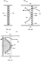
- FIGS. 6A-6B are cross-sections of an exemplary flow sensor 200 according to certain aspects of the present disclosure.
- the flow sensor 200 includes a rigid porous plate 202 having a plurality of contacts 206 distributed over the plate 202.
- a flexible disk 204 is attached, in certain embodiments, to the middle of plate 202.
- FIG. 6A depicts the configuration of the sensor 200 in the absence of a flow of gas past the sensor. All, or at least a majority, of the contacts 206 are in contact with or otherwise actuated by the flexible disk 204 so as to provide an indication that the disk is in a first configuration, for example flat against the plate 202.
- FIG. 6B depicts the sensor 200 while a gas flows past the sensor 200, as indicated by the flow path 250.
- the flexible disk 204 deflects as indicated by the arrows 260 to a second configuration wherein only sensors 206B are in contact with disk 204 while sensors 206A are not in contact with the disk 204.
- the number of contacts 206A vs. 206B provides an indication of the amount of deflection of disk 204 and therefore an indication of the rate of flow of the gas passing the sensor 200.
- the CPU 150 may combine the measurement from pressure sensor 126 and the measurement from flow sensor 200 to calculate a tidal volume.
- FIG. 6C depicts another embodiment 201 of the flow sensor according to certain aspects of the present disclosure.
- the flow sensor 201 has contacts 207 that are placed on the surface of a curved structure 203 that is disposed downstream of the flexible disk 205, with respect to the direction of measurement.
- the disk 205 bends away from the undeformed position, shown in dashed line, as indicated by the arrows 261 in response to the flow 251. As the disk 205 increasingly bends, it comes into contact with an increasing number of the contacts 207.
- the configuration of the disk 205 can be determined.
- FIG. 7A is an exploded view of an exemplary pressure sensor 280 according to certain aspects of the present disclosure.
- the sensor 280 includes a flexible disk 282 and a wall 284 that, in this embodiment, is circular.
- the wall 84 is formed on a substrate 296 with a series of conductive rings 286 formed on the substrate 296 within the wall 284.
- the disk 282 has, in this embodiment, a series of radial conductive strips 290, 292 formed on the underside (the disk 282 is shown as transparent in FIG. 7A to make the strips 290, 292 visible).
- the strips 292 are of variable length and arranged such that more strips 292 contact the rings 286 as the disk 282 is increasingly deformed.
- FIGS. 7B-7C are cross-sections of the assembled pressure sensor 280 of FIG. 7A according to certain aspects of the present disclosure.
- This disk 282 is sealingly attached to the wall 284 so as to form a interior volume 294 over the substrate 296.
- FIG. 7B shows the pressure sensor 280 in an initial configuration wherein the pressures within interior volume 294 and external volume 298 are equal. As the ambient pressure in the external volume 298 increases, the disk 282 will deform as shown in FIG. 7C and one or more of the radial strips 290, 292 (not visible in FIGS. 7B-7C ) on disk 282 will contact one or more of the concentric rings 286.
- the deformed shape of the disk 282 can be determined and therefore the pressure in the external volume 298 can be determined.
- the change in resistance may be non-linear with increased deformation, thereby at least partially compensating for any non-linear deformation of the disk 282 in response to an incremental change in the pressure in external volume 298.
- FIG. 8 is an exemplary display 300 of information provided by the processor 122 according to certain aspects of the present disclosure.
- the display 300 depicts examples of four sections 310, 320, 330, and 340 each displaying one or more examples of information. In certain embodiments, the display 300 may provide more or fewer elements of information.
- Section 310 displays an exemplary pressure-vs.-time curve 213, with the current time at the right.
- the plot is overlaid with a target peak inhalation pressure line 314 and a excess-pressure area 316.
- Section 320 displays the breath rate, i.e. the rate of inhalation intervals.
- the display 320 includes a marker 324 indicating the current time-averaged breath rate within a range bar 322 with minimum and maximum rates indicated with labels and shaded areas 326.
- the value is shown as a numerical value 325 that, in certain examples, may include a notation, for example a notation that the value is a 10-second average.
- Section 330 displays visual indicators 332 associated with various physical attributes.
- the box 334 displays the calculated blood-alcohol content based on the measured marker in the patient's breath.
- the box 336 would identify a drug, if detected.
- Section 340 displays the elapsed time since the initiation of a resuscitation event.
- the box 342 displays the value and box 344 displays the units of time, which may initially be “seconds” and later change to "minutes" after a certain time interval has elapsed.
- a resuscitation devices having an onboard processor provides improved access to accurate measurements of variables related to both the functioning of the resuscitation device as well as the physiological functioning of the patient. These variables may be easily read by the caregiver during the procedure and/or stored for later analysis or training purposes.
- top should be understood as referring to an arbitrary frame of reference, rather than to the ordinary gravitational frame of reference.
- a top surface, a bottom surface, a front surface, and a rear surface may extend upwardly, downwardly, diagonally, or horizontally in a gravitational frame of reference.
- a phrase such as an "aspect” does not imply that such aspect is essential to the subject technology or that such aspect applies to all configurations of the subject technology.
- a disclosure relating to an aspect may apply to all configurations, or one or more configurations.
- a phrase such as an aspect may refer to one or more aspects and vice versa.
- a phrase such as an "embodiment” does not imply that such embodiment is essential to the subject technology or that such embodiment applies to all configurations of the subject technology.
- a disclosure relating to an embodiment may apply to all embodiments, or one or more embodiments.
- a phrase such an embodiment may refer to one or more embodiments and vice versa.
Landscapes
- Health & Medical Sciences (AREA)
- Life Sciences & Earth Sciences (AREA)
- Pulmonology (AREA)
- Engineering & Computer Science (AREA)
- Veterinary Medicine (AREA)
- Public Health (AREA)
- Biomedical Technology (AREA)
- Heart & Thoracic Surgery (AREA)
- Animal Behavior & Ethology (AREA)
- General Health & Medical Sciences (AREA)
- Emergency Medicine (AREA)
- Hematology (AREA)
- Anesthesiology (AREA)
- Medical Informatics (AREA)
- Physics & Mathematics (AREA)
- Pathology (AREA)
- Biophysics (AREA)
- Surgery (AREA)
- Molecular Biology (AREA)
- Physiology (AREA)
- Critical Care (AREA)
- Computer Networks & Wireless Communication (AREA)
- Measurement Of The Respiration, Hearing Ability, Form, And Blood Characteristics Of Living Organisms (AREA)
- Percussion Or Vibration Massage (AREA)
- Artificial Intelligence (AREA)
- Computer Vision & Pattern Recognition (AREA)
- Psychiatry (AREA)
- Signal Processing (AREA)
Description
- The present disclosure generally relates to manual resuscitation devices and, in particular, a resuscitator that incorporates electronic sensing and processing.
- A resuscitator, sometimes referred to as a bag valve mask (BVM) or by the proprietary name "Ambu bag," is a hand-held device used to provide positive pressure ventilation to a patient who is not breathing or who is breathing inadequately. The resuscitator is a normal part of a "crash cart" used within a hospital or a resuscitation kit provided to ambulance crew. A resuscitator may also be used in an operating room to ventilate an anaesthetized patient prior to attachment of a mechanical ventilator. A resuscitator may be self-filling with air or provided with a source of breathing gas, such as oxygen, to increase the oxygenation of the patient.
US 2002/117173 describes a resuscitation system for resuscitation of asthma patients including a deflatable bag and a gas flow channel connected with said bag.US 2008/214948 describes a device for monitoring respiration comprising a duct containing a pressure sensor.
US 2007/261698 describes a patient vital sign monitoring device.
US 2012302910 describes a wireless ventilator reporting system. -
FIG. 1 depicts aconventional resuscitator 10 that is connected to a line 20 that provides oxygen or other breathing gas. Abag 14 is connected to amask 12 by aflow channel 16 that also has a valve assembly 1 8 that prevents backflow into thebag 14 and diverts exhaled gas to the atmosphere. An accumulator bag 22 is connected at the junction of thebag 14 and line 20 to accumulate a reservoir of oxygen such that the self-expansion of thebag 14 is not limited by the flow rate of line 20. - When using a resuscitator, there is a risk of over-inflating the lungs. This can lead to pressure damage to the lungs themselves and can also cause air to enter the stomach, causing gastric distension which can make it more difficult to inflate the lungs. Over-inflation may also cause the patient to vomit, which can cause additional airway problems beyond the original breathing difficulty.
-
FIG. 2 depicts anotherconventional resuscitator 30 having a mechanical pressure gauge 32 connected to theflow channel 16. The gauge 32 is marked with a green zone to indicate the desirable range of inflation pressure as well as yellow and red zones to indicate zones of excess inflation pressures. These types of mechanical gauges have limited resolution and reading such a gauge can be a challenge for caregivers as the gauge provides only an instantaneous reading and the caregiver cannot pay constant attention to the gauge as they may be performing other actions, for example striving to maintain a proper seal of the mask to the patient's face and mon itoring other symptoms and aspects of the patient's condition.
US Patent Publication 2002/117173 describes a resuscitation system including a deflatable bag and a gas flow channel connected with said bag and an indicator for detecting expiration flow and/or pressure within at least one of a flow channel and exhalation port associated with the bag to detect inadequacy in the expiratory component of ventilation during CPR.
German Patent Publication10132 269 describes a pressure sensor having s a base body and a circular disk shaped membrane that is connected to the base body around its outer edge,
US Patent 5155653 describes a capacitive pressure sensor including a diaphragm positioned within a pressure chamber with a central portion of the diaphragm positioned in the pressure chamber and an annular peripheral portion of the diaphragm positioned in a measurement chamber.
However, none of these teaches a method of measuring a parameter in a resuscitator by measuring contacts between a flexible disc and a porous plate to which it is coupled. - The resuscitator disclosed herein provides automatic monitoring of various aspects of the operation of the resuscitator as well as the patient's breathing and exhaled breath. The information gathered by the resuscitator can be provided in real time to the caregiver to aid in their resuscitation efforts or stored for later review and analysis. The invention is defined by the appended claim 1.
- According to the invention, a resuscitator is disclosed that includes a patient airway interface device, a bag, a flow passage coupled between the bag and patient airway interface device, and a sensor assembly. The sensor assembly may have a display, at least one sensor coupled to the flow passage and configured to provide a measurement of at least one parameter, and a processor coupled to the display and the at least one sensor. The processor may be configured to receive the measurement from the at least one sensor and provide information on the display based on the received measurement.
- In certain embodiments, a resuscitator is disclosed that includes a patient airway interface device, a bag, a flow passage coupled between the bag and patient airway interface device, and a sensor assembly having an indicator, at least one sensor coupled to the flow passage and configured to provide a measurement of at least one parameter, and a processor coupled to the indicator and the at least one sensor. The processor is configured to receive the measurement from the at least one sensor and actuate the indicator based on the received measurement.
- In certain examples, a method is disclosed that includes the steps of measuring at least one of a flow rate, a pressure, a temperature, a pH, and a chemical marker in the exhaled breath of a patient; and actuating an indicator so as to provide information related to at least one of a breath rate, a tidal volume, a pressure-vs-time curve, a presence of a chemical in the patient's breath, or a condition of the patient.
- The accompanying drawings, which are included to provide further understanding and are incorporated in and constitute a part of this specification, illustrate disclosed embodiments and together with the description serve to explain the principles of the disclosed embodiments. In the drawings:
-
FIG. 1 depicts a conventional resuscitator. -
FIG. 2 depicts a conventional resuscitator having a mechanical pressure gauge. -
FIG. 3 is a schematic representation of an exemplary resuscitator according to certain aspects of the present disclosure. -
FIG. 4 is a block diagram of the example sensor module that is part of the resuscitator ofFIG. 3 according to certain aspects of the present disclosure. -
FIG. 5 is a block diagram of the example processor that is part of the sensor module ofFIG. 4 according to certain aspects of the present disclosure. -
FIGS. 6A-6B are cross-sections of an exemplary flow sensor according to certain aspects of the present disclosure. -
FIG. 6C depicts another embodiment of the flow sensor according to certain aspects of the present disclosure. -
FIG. 7A is an exploded view of anexemplary pressure sensor 280 according to certain aspects of the present disclosure. -
FIGS. 7B-7C are cross-sections of the assembledpressure sensor 280 ofFIG. 7A according to certain aspects of the present disclosure. -
FIG. 8 is an exemplary display of information provided by the processor according to certain aspects of the present disclosure. - The resuscitator disclosed herein provides automatic monitoring of various aspects of the operation of the resuscitator as well as the patient's breathing and exhaled breath. The information gathered by the resuscitator can be provided in real-time to the caregiver to aid in their resuscitation efforts or stored for later review and analysis.
- In general, the disclosed resuscitator may include sensors that continuously or intermittently measure the pressure within the patient airway interface device and, during an exhalation by the patient, may measure one or more of chemical markers or particular chemicals, temperature, or pH. The resuscitator may also provide guidance to the caregiver such as a metronome of the optimal rate of inhalations, visual or audible alarms, and verbal communication.
- This disclosure describes embodiments that include a mask intended to placed over a patient's nose and/or mouth so as to form a sealed connection to the patient's airway. It should be understood that other types of patient airway interfaces may be used in place of the mask, for example an endotracheal tube, without departing from the scope of this disclosure. In general, the term "mask" includes all types of patient airway interface devices.
- In the following detailed description, numerous specific details are set forth to provide a full understanding of the present disclosure. It will be apparent, however, to one ordinarily skilled in the art that embodiments of the present disclosure may be practiced without some of the specific details. In other instances, well-known structures and techniques have not been shown in detail so as not to obscure the disclosure. In the referenced drawings, like numbered elements are the same or essentially similar. Reference numbers may have letter suffixes appended to indicate separate instances of a common element while being referred to generically by the same number without a suffix letter.
-
FIG. 1 depicts aconventional resuscitator 10. Aflexible mask 12 is configured to be placed over a patient's mouth and nose. Thebag 14 is connected to themask 12 by aflow channel 16. Avalve assembly 18 is attached to theflow channel 16 and includes a valve (not visible inFIG. 1 ) that prevents an exhaled breath from entering thebag 14 and diverts the exhaled breath out a port to the ambient atmosphere. Thisresuscitator 10 may be attached to a line 20 that provides oxygen, or other breathing gas, with an accumulator bag 22 connected at the junction of thebag 14 and line 20 to accumulate a reservoir of oxygen such that the self-expansion of thebag 14 is not limited by the flow rate of line 20. -
FIG. 2 depicts anotherconventional resuscitator 30 having a mechanical pressure gauge 32 connected to theflow channel 16. The gauge 32 is marked with agreen zone 32A to indicate the desirable range of inflation pressure as well as a yellow zone 32B and ared zone 32C to indicate zones of excess inflation pressures. As the gauge 32 provides only an instantaneous reading, there is no information regarding the history of the pressure being provided during the inhalation intervals or an average pressure. In addition, the mechanical inertia of the gauge 32 may delay or dampen the displayed value compared to the true instantaneous pressure in theflow channel 16. -
FIG. 3 is a schematic representation of anexemplary resuscitator 100 according to certain aspects of the present disclosure. Theresuscitator 100 includes abag 110 connected to amask 112 through aflow passage 114. In certain embodiments, thebag 110 is manually squeezed to force air or other breathing gas into the patient's lungs, after which thebag 110 self-expands to draw in new air or gas. Avalve assembly 116, containing a shutter valve (not visible inFIG. 3 ) or equivalent, is attached to theflow passage 114 to divert exhaled gas to the atmosphere. Asensor module 120 that includes adisplay 132 is coupled, in this example, to theflow passage 114 between themask 112 and thevalve assembly 116. In certain embodiments, thesensor assembly 120 is operatively coupled to thevalve assembly 116. Thesensor assembly 120 is discussed in greater detail with respect toFIG. 4 . In certain embodiments, themask 112 may be replaced by other types of breathing interface devices, for example an endotracheal tube or laryngeal mask airway (not shown inFIG. 3 ). In certain embodiments, thebag 110 draws in a breathing gas, for example oxygen, through an attachedline 118. In certain embodiments, a reservoir (not shown inFIG. 3 ) may be attached proximate to the junction of theline 118 andbag 110 to provide a large volume of the breathing gas such that the self-expansion of thebag 110 is not limited by the flow rate ofline 118. -
FIG. 4 is a block diagram of theexample sensor module 120 that is part of theresuscitator 100 ofFIG. 3 according to certain aspects of the present disclosure. Thesensor module 120 may include one or more of aprocessor 122, atimer 124, apressure sensor 126, achemical sensor 128, a communication (comm)module 130, adisplay 132, analarm 134, atemperature sensor 136, and apH sensor 138 that are interconnected by anetwork 142. Other elements common to electronic equipment, for example batteries or power supplies, touch screen interfaces, buttons, switches, and connectors, that are known to those of skill in the art are omitted so as not to obscure the disclosed features. Theprocessor 122 is discussed in greater detail with respect toFIG. 5 . Theflow sensor 200 is discussed in greater detail with respect toFIG. 6 . - The
pressure sensor 126 may be any device or mechanism configured to measure a gas pressure as are known to those of skill in the art. Thepressure sensor 126, as well as one or more of theother sensors pressure sensor 126, or other sensor, may be configured to detect an initial manual compression of theresuscitator bag 110 and trigger certain functions, for example turning on thedisplay 132 and powering up other elements of thesensor module 120. In certain embodiments, thepressure sensor 126 or other sensor may be configured to detect inactivity over a determined period of time and trigger other functions, for example turning off thedisplay 132 and placing the CPU in a low-power state to conserve power. - The
chemical sensor 128 may include one or more sensors that may be configured to detect in the patient's exhaled breath the presence or amount of certain chemical markers associated with certain physical attributes. In certain embodiments, thechemical sensor 128 may detect or measure markers associated with a level of alcohol or a drug in the patient's blood. In certain embodiments, thechemical sensor 128 may detect or measure a peroxide level in the patient's breath that may be associated with asthma. In certain embodiments, thechemical sensor 128 may measure one or more partial pressures of certain gases, for example carbon dioxide, in the patient's exhaled breath. - The
comm module 130 may include a wireless communication system, for example using Bluetooth® (IEEE 802.15.1) or Wi-Fi (IEEE 802.11) elements and protocols, that allows thesensor module 120 to communicate with external equipment. In certain embodiments, thecomm module 130 may include a port for connection of a communication cable, for example a CAT5 cable, to enable communication with external equipment. In certain embodiments, thecomm module 130 may include a port for a removable media, for example a USB port to connect to a "thumb drive," or a drive configured to read and/or write to a removable media, for example a CD or DVD. - The
display 132 may be any audio or visual device as known to those of skill in the art. In certain embodiments, thedisplay 132 may include a color or monochrome two-dimensional visual display that may include one or more of light emitting diodes (LEDs), liquid crystals, "electronic paper" such as electrophoretic display technologies, or electroluminescent elements. In certain embodiments, thedisplay 132 may be an audio device (132b inFIG. 3 ) such as a speaker, buzzer, or tone generator. In certain embodiments, thedisplay 132 may be a visual indicator (132a inFIG. 3 ) such as a single monochrome LED, a group of LEDs of various colors, an incandescent bulb, or a linear array of single light-emitting elements. - The
alarm 134 may include visual indicators, for example lights that may be selectably illuminated, or audible indicators, for example a speaker, a tone generator, or a buzzer. In certain embodiments, thealarm 134 may be a visual element provided on thedisplay 132. In certain embodiments, a visual or audible signal may be provided continuously or during non-alarm conditions. For example, a tone of a first frequency or combination of frequencies may be provided when the caregiver is operating the resuscitator within the desired range of pressure. In certain embodiments, the visual or audible signal may change, for example to a tone of a second frequency or combination of frequencies, when the pressure exceeds the desired range. - In certain examples, the
resuscitator 100 may have a disposable portion, for example thebag 110,flow passage 114, andmask 112, to which a re-useable portion, for example thesensor module 120, is attached. In certain examples, the disposable portion may include a sensor, for example a flow sensor such as shown inFIG. 6 , that functionally connects to theprocessor 122. In certain examples, theentire resuscitator 100 may be disposable. -
FIG. 5 is a block diagram of theexample processor 122 that is part of thesensor module 120 ofFIG. 4 according to certain aspects of the present disclosure. Theprocessor 122 may include one or more of a central processor unit (CPU) 150, adisplay driver 152, an analog-to-digital converter (ADC) 154, analarm driver 156, acomm module 158, amemory 160, atimer 162, aclock 164, and aperipheral control interface 166 that are interconnected by aninternal network 168. Various components may be connected directly to other modules of thesensor module 122, for example thedisplay driver 152 may be connected directly to thedisplay 132. In certain examples, various components may be connected to other modules of thesensor module 122 through theinternal network 168,comm module 158, and an external network. - The
memory 160 may include transitory computer-readable media such as random access memory (RAM) as well as non-transitory computer-readable media that may include magnetically encodable media such as hard disks, solid-state memory (SSD), flash memory data storage devices such as thumb drives, and read-only memory (ROM). Thememory 160 may be configured to store operational instructions that may be retrieved by theCPU 150 to configure theCPU 150 so as to be able to perform various functions. Thememory 160 may also contain a look-up table comprising limits or other information that may be used to interpret the measurements of the various sensors, alone or in combination. In certain embodiments, the memory may store instructions and information related to the operation and testing of the resuscitator, for example battery life, self-test procedures, errors code, etc. In certain examples, thememory 160 may store calibration instructions and information for use in calibrating elements of theresuscitator 100. - The peripheral controls interface 166 may be coupled to external devices within the
sensor module 120, for example a touchscreen, buttons, and switches, to allow a user to interact with theCPU 150 so as to initiate desired functions. In certain examples, the peripheral controls interface 166 may be operatively coupled to thevalve assembly 116 so as, for example, to control a restrictor (not shown inFIG. 3 ) that maintains a desired minimum pressure within themask 112. - In certain examples, the
CPU 150 may be configured to receive measurements made by thepressure sensor 126 through theADC 154. In certain examples, theCPU 150 may store a portion of these measurements in thememory 160. In certain examples, theCPU 150 may display a portion of the measurements on the display, for example as a measurement-vs.-time curve that may be overlaid with zones of pressure indicating desirable and/or undesirable ranges of pressure. In certain examples, theCPU 150 may receive measurements from one or morechemical sensors 128 and analyze the measurements. In certain embodiments, theCPU 150 may provide indications to the caregiver of certain physical conditions associated with the measurements of thechemical sensors 128, for example a warning that the patient has a certain level of an anesthetizing agent in their blood. In certain examples, theCPU 150 may provide other information or warnings to the caregiver related to the measured chemical markers in the exhaled breath as known to those of skill in the art. - In certain examples, the
CPU 150 may provide real-time guidance to a caregiver using theresuscitator 100 by providing a visual or audible metronome signal through thedisplay 132 oralarm 134 at a target rate of inhalation intervals or cycles. In certain examples, theCPU 150 may adjust the metronome signal to an upper or lower value, within an acceptable range of rates of inhalation intervals, based on the rate of inhalation intervals as measured by thepressure sensor 126. - In certain examples, the
CPU 150 may provide real-time guidance to a caregiver using spoken phrases, for example "current rate is 20 breaths per minute, please slow to 12 breaths per minute," through adisplay 132 that comprises a speaker. In certain examples, theCPU 150 may provide real-time guidance to a caregiver through adisplay 132 that comprises a flashing, variably colored light, for example a light flashing at a target inhalation interval with a color that indicates whether the resuscitator is currently being actuated at a rate that is higher than, within, or less than an acceptable range. In certain examples, the current rate being displayed may be a time-average of a past number, for example three, inhalation intervals. - In certain examples, the
CPU 150 may combine measurements from multiple sensors to calculate other parameters related to the patient's condition or the resuscitation actions, for example a tidal volume or exhalation pressure. - In certain examples, the
CPU 150 may store an entire history of a resuscitation event, for example including one or more of pressures, partial pressures, and measured chemical markers, and download this history through thecomm modules resuscitator 100 were used with a manikin or other training aid, this history may provide the ability to quantitatively evaluate the performance of the user. - In certain examples, the
CPU 150 may be configured to accept new programming instructions, for example built-in operating system (BIOS) programming and settings, firmware, or software, or new information , for example a look-up table of limits and parameters, and store these instructions and information inmemory 160. -
FIGS. 6A-6B are cross-sections of anexemplary flow sensor 200 according to certain aspects of the present disclosure. Theflow sensor 200 includes a rigidporous plate 202 having a plurality ofcontacts 206 distributed over theplate 202. Aflexible disk 204 is attached, in certain embodiments, to the middle ofplate 202.FIG. 6A depicts the configuration of thesensor 200 in the absence of a flow of gas past the sensor. All, or at least a majority, of thecontacts 206 are in contact with or otherwise actuated by theflexible disk 204 so as to provide an indication that the disk is in a first configuration, for example flat against theplate 202. -
FIG. 6B depicts thesensor 200 while a gas flows past thesensor 200, as indicated by theflow path 250. Theflexible disk 204 deflects as indicated by thearrows 260 to a second configuration whereinonly sensors 206B are in contact withdisk 204 whilesensors 206A are not in contact with thedisk 204. The number ofcontacts 206A vs. 206B provides an indication of the amount of deflection ofdisk 204 and therefore an indication of the rate of flow of the gas passing thesensor 200. - If a
sensor 200 is placed in theflow passage 114 between themask 112 and thevalve assembly 116, or in the exhalation port outside of thevalve assembly 116, it may be possible to measure the exhalation flow rate. In certain embodiments, theCPU 150 may combine the measurement frompressure sensor 126 and the measurement fromflow sensor 200 to calculate a tidal volume. -
FIG. 6C depicts anotherembodiment 201 of the flow sensor according to certain aspects of the present disclosure. Theflow sensor 201 has contacts 207 that are placed on the surface of acurved structure 203 that is disposed downstream of theflexible disk 205, with respect to the direction of measurement. Thedisk 205 bends away from the undeformed position, shown in dashed line, as indicated by thearrows 261 in response to theflow 251. As thedisk 205 increasingly bends, it comes into contact with an increasing number of the contacts 207. By comparing the number and position ofcontacts 207B that are in contact with thedisk 205 to the number and location of thecontacts 207A that are not in contact with thedisk 205, the configuration of thedisk 205 can be determined. -
FIG. 7A is an exploded view of anexemplary pressure sensor 280 according to certain aspects of the present disclosure. Thesensor 280 includes aflexible disk 282 and awall 284 that, in this embodiment, is circular. In this embodiment, the wall 84 is formed on asubstrate 296 with a series ofconductive rings 286 formed on thesubstrate 296 within thewall 284. Thedisk 282 has, in this embodiment, a series of radialconductive strips disk 282 is shown as transparent inFIG. 7A to make thestrips strips 292 are of variable length and arranged such thatmore strips 292 contact therings 286 as thedisk 282 is increasingly deformed. -
FIGS. 7B-7C are cross-sections of the assembledpressure sensor 280 ofFIG. 7A according to certain aspects of the present disclosure. Thisdisk 282 is sealingly attached to thewall 284 so as to form ainterior volume 294 over thesubstrate 296.FIG. 7B shows thepressure sensor 280 in an initial configuration wherein the pressures withininterior volume 294 andexternal volume 298 are equal. As the ambient pressure in theexternal volume 298 increases, thedisk 282 will deform as shown inFIG. 7C and one or more of theradial strips 290, 292 (not visible inFIGS. 7B-7C ) ondisk 282 will contact one or more of the concentric rings 286. By determining which rings 286 are interconnected by contact with thestrips rings 286, using a resistance measurement device (not shown inFIGS. 7A-7C ), the deformed shape of thedisk 282 can be determined and therefore the pressure in theexternal volume 298 can be determined. With the appropriate arrangement of theradial strips 292, the change in resistance may be non-linear with increased deformation, thereby at least partially compensating for any non-linear deformation of thedisk 282 in response to an incremental change in the pressure inexternal volume 298. - It will be apparent that the disposition of the
concentric rings 286 and radialconductive strips disk 282 while radial conductive lines of varying length are provided on the surface ofsubstrate 296 within thewall 284 without departing from the scope of this disclosure. Methods of selectably measuring the resistance between pairs of therings 286, in the embodiment shown inFIGS. 7A-7C , or of radial conductive lines formed on the substrate, in an alternate embodiment, are known to those of skill in the art and are not shown herein. -
FIG. 8 is anexemplary display 300 of information provided by theprocessor 122 according to certain aspects of the present disclosure. Thedisplay 300 depicts examples of foursections display 300 may provide more or fewer elements of information. -
Section 310 displays an exemplary pressure-vs.-time curve 213, with the current time at the right. The plot is overlaid with a target peakinhalation pressure line 314 and a excess-pressure area 316. -
Section 320 displays the breath rate, i.e. the rate of inhalation intervals. Thedisplay 320 includes amarker 324 indicating the current time-averaged breath rate within arange bar 322 with minimum and maximum rates indicated with labels and shadedareas 326. The value is shown as anumerical value 325 that, in certain examples, may include a notation, for example a notation that the value is a 10-second average. -
Section 330 displaysvisual indicators 332 associated with various physical attributes. Thebox 334 displays the calculated blood-alcohol content based on the measured marker in the patient's breath. Thebox 336 would identify a drug, if detected. -
Section 340 displays the elapsed time since the initiation of a resuscitation event. Thebox 342 displays the value andbox 344 displays the units of time, which may initially be "seconds" and later change to "minutes" after a certain time interval has elapsed. - It can be seen that the disclosed embodiments of a resuscitation devices having an onboard processor provides improved access to accurate measurements of variables related to both the functioning of the resuscitation device as well as the physiological functioning of the patient. These variables may be easily read by the caregiver during the procedure and/or stored for later analysis or training purposes.
- The previous description is provided to enable any person skilled in the art to practice the various aspects described herein. While the foregoing has described what are considered to be the best mode and/or other examples, it is understood that various modifications to these aspects will be readily apparent to those skilled in the art, and the generic principles defined herein may be applied to other aspects. Thus, the claims are not intended to be limited to the aspects shown herein, but is to be accorded the full scope consistent with the language claims, wherein reference to an element in the singular is not intended to mean "one and only one" unless specifically so stated, but rather "one or more." Unless specifically stated otherwise, the terms "a set" and "some" refer to one or more. Pronouns in the masculine (e.g., his) include the feminine and neuter gender (e.g., her and its) and vice versa. Headings and subheadings, if any, are used for convenience only and do not limit the invention.
- It is understood that the specific order or hierarchy of steps in the processes disclosed is an illustration of exemplary approaches. Based upon design preferences, it is understood that the specific order or hierarchy of steps in the processes may be rearranged. Some of the steps may be performed simultaneously. The accompanying method claims present elements of the various steps in a sample order, and are not meant to be limited to the specific order or hierarchy presented.
- Terms such as "top," "bottom," "front," "rear" and the like as used in this disclosure should be understood as referring to an arbitrary frame of reference, rather than to the ordinary gravitational frame of reference. Thus, a top surface, a bottom surface, a front surface, and a rear surface may extend upwardly, downwardly, diagonally, or horizontally in a gravitational frame of reference.
- A phrase such as an "aspect" does not imply that such aspect is essential to the subject technology or that such aspect applies to all configurations of the subject technology. A disclosure relating to an aspect may apply to all configurations, or one or more configurations. A phrase such as an aspect may refer to one or more aspects and vice versa. A phrase such as an "embodiment" does not imply that such embodiment is essential to the subject technology or that such embodiment applies to all configurations of the subject technology. A disclosure relating to an embodiment may apply to all embodiments, or one or more embodiments. A phrase such an embodiment may refer to one or more embodiments and vice versa.
- The word "exemplary" is used herein to mean "serving as an example or illustration." Any aspect or design described herein as "exemplary" is not necessarily to be construed as preferred or advantageous over other aspects or designs.
- The terms "include," "have," and the like are intended to be inclusive in a manner similar to the term "comprise" as "comprise" is interpreted when employed as a transitional word in a claim.
Claims (15)
- A resuscitator comprising:a patient airway interface device;a bag(110);a flow passage (114) coupled between the bag (110) and patient airway interface device;anda sensor assembly (120) comprising:a display (132);at least one sensor (126, 128, 136, 138, 200) coupled to the flow passage and configured to provide a measurement of at least one parameter, the sensor comprising a rigid porous plate (202) having a plurality of contacts (206) and a flexible disk (204) attached to the rigid porous plate (202); anda processor (122) coupled to the display and the at least one sensor (126, 128, 136, 138, 200), the processor (122) configured to receive the measurement from the at least one sensor and provide information on the display (132) based on the received measurement,wherein the comparison of the contacts in contact with the flexible disk (204) and contacts not in contact with the flexible disk (204) provides an indication of the amount of deflection of disk (204) and therefore an indication of the rate of flow of gas passing the sensor.
- The resuscitator of claim 1, wherein:the at least one sensor comprises a pressure sensor; andthe information provided on the display comprises pressure information.
- The resuscitator of claim 2, wherein the pressure information comprises a pressure-vs-time curve.
- The resuscitator of claim 2, wherein the information further comprises real-time guidance related to operation of the resuscitator.
- The resuscitator of claim 4, wherein the real-time guidance comprises a metronome signal of a target rate of inhalation intervals.
- The resuscitator of claim 5, wherein the metronome signal comprises an audible signal.
- The resuscitator of claim 5, wherein the processor is configured to adjust the metronome signal based on a current measured rate of inhalation intervals.
- The resuscitator of claim 2, wherein:the at least one sensor further comprises a flow sensor (200) ; andthe information provided on the display (132) comprises a tidal volume.
- The resuscitator of claim 8, wherein the flexible disk (204) has a first configuration associated with a zero flow rate and a plurality of second positions respectively associated with a plurality of flow rates.
- The resuscitator of claim 1, wherein:the at least one sensor further comprises a chemical sensor (128) configured to detect chemical markers associated with certain physical attributes; andthe information comprises information on the chemical markers.
- The resuscitator of claim 10, wherein the information on the chemical markers comprises information regarding one or more of a level of alcohol in the patient's blood, a level of a drug in the patient's blood, a peroxide level in an exhaled breath of a patient, or a pH of the exhaled breath.
- The resuscitator of claim 1, wherein:the sensor assembly (120) further comprises a memory (160) coupled to the processor (122); andthe processor is configured to store a portion of the measurement of at least one parameter in the memory (160).
- The resuscitator of claim 12, wherein the processor (122) is configured to retrieve a portion of the measurement from the memory (160) and provide the retrieved portion of the measurement to an external system.
- The resuscitator of claim 13, wherein the sensor assembly (120) comprises a communication module (130) coupled to the processor (122) and configured to communicate wirelessly with the external system.
- The resuscitator of claim 1, wherein the patient airway interface device comprises an endotracheal tube.
Applications Claiming Priority (2)
| Application Number | Priority Date | Filing Date | Title |
|---|---|---|---|
| US13/829,281 US9446211B2 (en) | 2013-03-14 | 2013-03-14 | Resuscitation device with onboard processor |
| PCT/US2014/019634 WO2014158726A1 (en) | 2013-03-14 | 2014-02-28 | Resuscitation device with onboard processor |
Publications (2)
| Publication Number | Publication Date |
|---|---|
| EP2968803A1 EP2968803A1 (en) | 2016-01-20 |
| EP2968803B1 true EP2968803B1 (en) | 2018-08-15 |
Family
ID=50290303
Family Applications (1)
| Application Number | Title | Priority Date | Filing Date |
|---|---|---|---|
| EP14711093.6A Not-in-force EP2968803B1 (en) | 2013-03-14 | 2014-02-28 | Resuscitation device with onboard processor |
Country Status (3)
| Country | Link |
|---|---|
| US (3) | US9446211B2 (en) |
| EP (1) | EP2968803B1 (en) |
| WO (1) | WO2014158726A1 (en) |
Families Citing this family (31)
| Publication number | Priority date | Publication date | Assignee | Title |
|---|---|---|---|---|
| US11129950B2 (en) * | 2012-11-19 | 2021-09-28 | The General Hospital Corporation | System and method for monitoring resuscitation or respiratory mechanics of a patient |
| US9446211B2 (en) * | 2013-03-14 | 2016-09-20 | Carefusion 2200, Inc. | Resuscitation device with onboard processor |
| CA2911238A1 (en) * | 2013-05-13 | 2014-11-20 | Karl Kufner Gmbh & Co. Kg | Device and method for artificial respiration in emergencies |
| US9586015B1 (en) * | 2013-09-17 | 2017-03-07 | Chance S. Lindner | Duty-cycle indicator for manual resuscitation/ventilation |
| US20150096559A1 (en) * | 2013-10-04 | 2015-04-09 | The Johns Hopkins University | Manual ventilation feedback sensor for use in clinical and training settings |
| US8973580B1 (en) * | 2014-01-09 | 2015-03-10 | Osborne Williams | Portable manual ventilation device |
| US10532174B2 (en) * | 2014-02-21 | 2020-01-14 | Masimo Corporation | Assistive capnography device |
| US20150327807A1 (en) * | 2014-05-13 | 2015-11-19 | Karl Kuefner GmbH & Co. KG | Device and method for monitoring compressions at a cardiac massage |
| AU362450S (en) * | 2014-11-07 | 2015-07-08 | Laerdal Medical As | Mask to use for ventilation of newborns |
| WO2016123562A1 (en) * | 2015-01-29 | 2016-08-04 | Los Angeles Biomedical Research Institute | Adjustably controlling rescue or assisted breaths |
| JP5977850B1 (en) * | 2015-02-25 | 2016-08-24 | 株式会社Icst | Cuff pressure adjusting device |
| US20220111167A1 (en) * | 2015-06-08 | 2022-04-14 | Archeon | Device for diagnosing the efficacy of ventilation of a patient and method for determining the ventilatory efficacy of a patient |
| FR3036944B1 (en) * | 2015-06-08 | 2021-01-22 | Polycaptil | DEVICE FOR DIAGNOSING THE EFFICIENCY OF THE VENTILATION OF A PATIENT AND METHOD OF VENTILATION OF A PATIENT |
| DE102015215708A1 (en) * | 2015-08-18 | 2017-02-23 | Linde Aktiengesellschaft | An oxygen supply device and system for detecting and / or treating a disease or medical condition of a patient |
| PE20171695A1 (en) * | 2016-05-18 | 2017-11-28 | Pontificia Univ Catolica Del Peru | MANUAL RESUSCITOR WITH ADJUSTABLE VOLUME |
| WO2018065448A1 (en) | 2016-10-05 | 2018-04-12 | Koninklijke Philips N.V. | An apparatus and method for harvesting energy during bag valve mask ventilation |
| IT201700117302A1 (en) * | 2017-10-17 | 2019-04-17 | Andrea Pagani | Device with flow-meter function for regulation of manual lung ventilation |
| US11007344B2 (en) * | 2018-01-31 | 2021-05-18 | The Aga Khan University | Resuscitation device |
| JP6961530B2 (en) * | 2018-04-27 | 2021-11-05 | 日本光電工業株式会社 | Patient treatment system and monitoring device |
| JP7174128B2 (en) * | 2018-04-27 | 2022-11-17 | 日本光電工業株式会社 | Patient care system and monitoring device |
| WO2020140121A2 (en) * | 2018-12-28 | 2020-07-02 | The Regents Of The University Of California | Tracheostomy support system |
| AU2020271997B2 (en) * | 2019-04-12 | 2025-05-15 | ResMed Pty Ltd | Respiratory pressure therapy system |
| CN113766940B (en) * | 2019-04-26 | 2024-10-18 | 通用电气精准医疗有限责任公司 | Systems and methods for delivering sustained respiration to a neonate |
| FR3106068B1 (en) * | 2020-01-09 | 2023-06-16 | Air Liquide | Apparatus for supplying oxygen to a vehicle user and vehicle comprising such apparatus |
| WO2021167870A1 (en) * | 2020-02-18 | 2021-08-26 | Rush University Medical Center | Device to monitor and alarm manual ventilation parameters during cardiopulmonary resuscitation |
| US11727826B2 (en) | 2020-03-02 | 2023-08-15 | Ryan Ziegler | Resuscitation training device and method of use |
| US20210322704A1 (en) * | 2020-04-17 | 2021-10-21 | Edward D. Lin | Methods of respiratory support and related apparatus |
| CN111729170A (en) * | 2020-06-23 | 2020-10-02 | 包蕾 | Severe medical science branch of academic or vocational study respiratory recovery ware |
| FR3118694B1 (en) * | 2021-01-08 | 2024-05-10 | Air Liquide Medical Systems | Autonomous box for monitoring ventilation delivered during cardiopulmonary resuscitation |
| USD1057159S1 (en) | 2022-03-29 | 2025-01-07 | Masimo Corporation | Electronic measurement device |
| USD1057160S1 (en) | 2022-03-29 | 2025-01-07 | Masimo Corporation | Electronic measurement device |
Citations (7)
| Publication number | Priority date | Publication date | Assignee | Title |
|---|---|---|---|---|
| US5155653A (en) * | 1991-08-14 | 1992-10-13 | Maclean-Fogg Company | Capacitive pressure sensor |
| US20020117173A1 (en) * | 2001-02-23 | 2002-08-29 | Lawrence A. Lynn | Asthma resuscitation system and method |
| DE10132269A1 (en) * | 2001-07-04 | 2003-01-16 | Endress & Hauser Gmbh & Co Kg | Membrane type pressure sensor has a circular membrane that is divided into concentric areas of varying cross section, so that pressure can be measured accurately over a wide range |
| US20070261698A1 (en) * | 2006-05-15 | 2007-11-15 | Eugene Palatnik | Intubation verification and respiratory gas monitoring device and the Method Thereof |
| US20080053445A1 (en) * | 2006-08-29 | 2008-03-06 | Kroupa Kevin D | Cardiopulminary resuscitation timer |
| US20080214948A1 (en) * | 2007-02-02 | 2008-09-04 | Helge Myklebust | Method and apparatus for monitoring respiration |
| US20120302910A1 (en) * | 2011-05-23 | 2012-11-29 | Zoll Medical Corporation | Wireless ventilator reporting |
Family Cites Families (17)
| Publication number | Priority date | Publication date | Assignee | Title |
|---|---|---|---|---|
| US5381299A (en) * | 1994-01-28 | 1995-01-10 | United Technologies Corporation | Capacitive pressure sensor having a substrate with a curved mesa |
| US6000396A (en) * | 1995-08-17 | 1999-12-14 | University Of Florida | Hybrid microprocessor controlled ventilator unit |
| JP3564878B2 (en) * | 1996-07-04 | 2004-09-15 | 松下電器産業株式会社 | Biological signal detection device |
| US7378856B2 (en) * | 2001-10-24 | 2008-05-27 | Pressure Profile Systems | Array sensor electronics |
| WO2003084396A1 (en) * | 2002-04-01 | 2003-10-16 | Aspect Medical Systems, Inc. | System and method of assessment of arousal, pain and stress during anesthesia and sedation |
| US8111165B2 (en) * | 2002-10-02 | 2012-02-07 | Orthocare Innovations Llc | Active on-patient sensor, method and system |
| JP2007512876A (en) * | 2003-12-01 | 2007-05-24 | シエラ メディカル テクノロジ インコーポレイテッド | System for monitoring, diagnosing and treating respiratory conditions |
| US20070074579A1 (en) * | 2005-10-03 | 2007-04-05 | Honeywell International Inc. | Wireless pressure sensor and method of forming same |
| US20110263997A1 (en) * | 2006-04-20 | 2011-10-27 | Engineered Vigilance, Llc | System and method for remotely diagnosing and managing treatment of restrictive and obstructive lung disease and cardiopulmonary disorders |
| US7383737B1 (en) * | 2007-03-29 | 2008-06-10 | Delphi Technologies, Inc | Capacitive pressure sensor |
| DE102008028662A1 (en) * | 2007-06-18 | 2008-12-24 | Weinmann Geräte für Medizin GmbH + Co. KG | Respiration parameters and/or physiological parameters e.g. inspiration volume, measuring and signaling device for patient, has measuring unit e.g. pressure sensor, measuring parameters generated from data by using algorithms |
| BRPI0703836B8 (en) * | 2007-09-06 | 2018-09-18 | Intermed Equipamento Medico Hospitalar Ltda | double obstruction flow sensor |
| EP4600969A3 (en) * | 2010-04-08 | 2025-09-10 | Zoll Medical Corporation | Wireless ventilator reporting |
| CN102819330B (en) * | 2011-06-07 | 2016-07-06 | 索尼爱立信移动通讯有限公司 | Electronic equipment, pressure detection method and pressure-detecting device |
| US8966999B2 (en) * | 2011-06-17 | 2015-03-03 | Microsoft Corporation | Pressure sensor linearization |
| US9539389B2 (en) * | 2012-02-08 | 2017-01-10 | Stmicroelectronics, Inc. | Wireless flow sensor using present flow rate data |
| US9446211B2 (en) * | 2013-03-14 | 2016-09-20 | Carefusion 2200, Inc. | Resuscitation device with onboard processor |
-
2013
- 2013-03-14 US US13/829,281 patent/US9446211B2/en active Active
-
2014
- 2014-02-28 WO PCT/US2014/019634 patent/WO2014158726A1/en not_active Ceased
- 2014-02-28 EP EP14711093.6A patent/EP2968803B1/en not_active Not-in-force
-
2016
- 2016-08-17 US US15/239,747 patent/US10022513B2/en not_active Expired - Fee Related
-
2018
- 2018-06-20 US US16/013,830 patent/US11135383B2/en active Active
Patent Citations (7)
| Publication number | Priority date | Publication date | Assignee | Title |
|---|---|---|---|---|
| US5155653A (en) * | 1991-08-14 | 1992-10-13 | Maclean-Fogg Company | Capacitive pressure sensor |
| US20020117173A1 (en) * | 2001-02-23 | 2002-08-29 | Lawrence A. Lynn | Asthma resuscitation system and method |
| DE10132269A1 (en) * | 2001-07-04 | 2003-01-16 | Endress & Hauser Gmbh & Co Kg | Membrane type pressure sensor has a circular membrane that is divided into concentric areas of varying cross section, so that pressure can be measured accurately over a wide range |
| US20070261698A1 (en) * | 2006-05-15 | 2007-11-15 | Eugene Palatnik | Intubation verification and respiratory gas monitoring device and the Method Thereof |
| US20080053445A1 (en) * | 2006-08-29 | 2008-03-06 | Kroupa Kevin D | Cardiopulminary resuscitation timer |
| US20080214948A1 (en) * | 2007-02-02 | 2008-09-04 | Helge Myklebust | Method and apparatus for monitoring respiration |
| US20120302910A1 (en) * | 2011-05-23 | 2012-11-29 | Zoll Medical Corporation | Wireless ventilator reporting |
Also Published As
| Publication number | Publication date |
|---|---|
| US20140275820A1 (en) | 2014-09-18 |
| US9446211B2 (en) | 2016-09-20 |
| EP2968803A1 (en) | 2016-01-20 |
| US20180304033A1 (en) | 2018-10-25 |
| US20160375210A1 (en) | 2016-12-29 |
| WO2014158726A1 (en) | 2014-10-02 |
| US10022513B2 (en) | 2018-07-17 |
| US11135383B2 (en) | 2021-10-05 |
Similar Documents
| Publication | Publication Date | Title |
|---|---|---|
| US11135383B2 (en) | Resuscitation device with onboard processor | |
| US12029857B2 (en) | Flow sensor for ventilation | |
| EP2919650B1 (en) | A system and method for monitoring resuscitation or respiratory mechanics of a patient | |
| ES2813409T3 (en) | Compliance Assist Module for an Inhaler | |
| US8579829B2 (en) | System and method for monitoring breathing | |
| US20190117930A1 (en) | Assistive capnography device | |
| US8083684B2 (en) | Intubation verification and respiratory gas monitoring device and the method thereof | |
| WO2004049912A2 (en) | Respiratory monitoring systems and methods | |
| US20130281885A1 (en) | Device with external pressure sensors for enhancing patient care and methods of using same | |
| JP3225938U (en) | Improved breath sampling device | |
| CN106462660A (en) | Lung ventilation apparatus | |
| CN110404146A (en) | Patient treatment system and monitoring device | |
| US20230405248A1 (en) | Respiratory Tidal Volume Monitor and Feedback Device | |
| US10556076B2 (en) | Cuff pressure adjusting device | |
| WO2015040548A1 (en) | Spirometer | |
| EP2303119B1 (en) | Ventilation analysis and monitoring | |
| WO2011068741A1 (en) | Sensing endotracheal tube location | |
| CN204379924U (en) | Breathing auxiliary device capable of displaying breathing condition | |
| JP4547496B2 (en) | Laryngoscope system for tracheal intubation | |
| JP7174128B2 (en) | Patient care system and monitoring device | |
| US20230201516A1 (en) | Breath detection apparatus and method for breath detection | |
| JP2000217921A (en) | Gas supply control device |
Legal Events
| Date | Code | Title | Description |
|---|---|---|---|
| PUAI | Public reference made under article 153(3) epc to a published international application that has entered the european phase |
Free format text: ORIGINAL CODE: 0009012 |
|
| 17P | Request for examination filed |
Effective date: 20151007 |
|
| AK | Designated contracting states |
Kind code of ref document: A1 Designated state(s): AL AT BE BG CH CY CZ DE DK EE ES FI FR GB GR HR HU IE IS IT LI LT LU LV MC MK MT NL NO PL PT RO RS SE SI SK SM TR |
|
| AX | Request for extension of the european patent |
Extension state: BA ME |
|
| DAX | Request for extension of the european patent (deleted) | ||
| PUAG | Search results despatched under rule 164(2) epc together with communication from examining division |
Free format text: ORIGINAL CODE: 0009017 |
|
| STAA | Information on the status of an ep patent application or granted ep patent |
Free format text: STATUS: EXAMINATION IS IN PROGRESS |
|
| 17Q | First examination report despatched |
Effective date: 20170808 |
|
| B565 | Issuance of search results under rule 164(2) epc |
Effective date: 20170808 |
|
| RIC1 | Information provided on ipc code assigned before grant |
Ipc: A61B 5/00 20060101ALN20170803BHEP Ipc: A61M 16/00 20060101AFI20170803BHEP |
|
| RAP1 | Party data changed (applicant data changed or rights of an application transferred) |
Owner name: VYAIRE MEDICAL CONSUMABLES LLC |
|
| RIC1 | Information provided on ipc code assigned before grant |
Ipc: A61M 16/04 20060101ALI20171221BHEP Ipc: A61B 5/01 20060101ALI20171221BHEP Ipc: A61M 16/00 20060101AFI20171221BHEP Ipc: A61M 16/20 20060101ALI20171221BHEP Ipc: A61B 5/08 20060101ALI20171221BHEP Ipc: A61M 16/08 20060101ALI20171221BHEP |
|
| GRAP | Despatch of communication of intention to grant a patent |
Free format text: ORIGINAL CODE: EPIDOSNIGR1 |
|
| STAA | Information on the status of an ep patent application or granted ep patent |
Free format text: STATUS: GRANT OF PATENT IS INTENDED |
|
| INTG | Intention to grant announced |
Effective date: 20180316 |
|
| RAP1 | Party data changed (applicant data changed or rights of an application transferred) |
Owner name: VYAIRE MEDICAL CONSUMABLES LLC |
|
| INTG | Intention to grant announced |
Effective date: 20180316 |
|
| GRAS | Grant fee paid |
Free format text: ORIGINAL CODE: EPIDOSNIGR3 |
|
| GRAA | (expected) grant |
Free format text: ORIGINAL CODE: 0009210 |
|
| STAA | Information on the status of an ep patent application or granted ep patent |
Free format text: STATUS: THE PATENT HAS BEEN GRANTED |
|
| AK | Designated contracting states |
Kind code of ref document: B1 Designated state(s): AL AT BE BG CH CY CZ DE DK EE ES FI FR GB GR HR HU IE IS IT LI LT LU LV MC MK MT NL NO PL PT RO RS SE SI SK SM TR |
|
| REG | Reference to a national code |
Ref country code: CH Ref legal event code: EP Ref country code: GB Ref legal event code: FG4D Ref country code: AT Ref legal event code: REF Ref document number: 1029037 Country of ref document: AT Kind code of ref document: T Effective date: 20180815 |
|
| REG | Reference to a national code |
Ref country code: IE Ref legal event code: FG4D |
|
| REG | Reference to a national code |
Ref country code: DE Ref legal event code: R096 Ref document number: 602014030409 Country of ref document: DE |
|
| REG | Reference to a national code |
Ref country code: NL Ref legal event code: MP Effective date: 20180815 |
|
| REG | Reference to a national code |
Ref country code: LT Ref legal event code: MG4D |
|
| REG | Reference to a national code |
Ref country code: AT Ref legal event code: MK05 Ref document number: 1029037 Country of ref document: AT Kind code of ref document: T Effective date: 20180815 |
|
| PG25 | Lapsed in a contracting state [announced via postgrant information from national office to epo] |
Ref country code: RS Free format text: LAPSE BECAUSE OF FAILURE TO SUBMIT A TRANSLATION OF THE DESCRIPTION OR TO PAY THE FEE WITHIN THE PRESCRIBED TIME-LIMIT Effective date: 20180815 Ref country code: IS Free format text: LAPSE BECAUSE OF FAILURE TO SUBMIT A TRANSLATION OF THE DESCRIPTION OR TO PAY THE FEE WITHIN THE PRESCRIBED TIME-LIMIT Effective date: 20181215 Ref country code: FI Free format text: LAPSE BECAUSE OF FAILURE TO SUBMIT A TRANSLATION OF THE DESCRIPTION OR TO PAY THE FEE WITHIN THE PRESCRIBED TIME-LIMIT Effective date: 20180815 Ref country code: NO Free format text: LAPSE BECAUSE OF FAILURE TO SUBMIT A TRANSLATION OF THE DESCRIPTION OR TO PAY THE FEE WITHIN THE PRESCRIBED TIME-LIMIT Effective date: 20181115 Ref country code: GR Free format text: LAPSE BECAUSE OF FAILURE TO SUBMIT A TRANSLATION OF THE DESCRIPTION OR TO PAY THE FEE WITHIN THE PRESCRIBED TIME-LIMIT Effective date: 20181116 Ref country code: BG Free format text: LAPSE BECAUSE OF FAILURE TO SUBMIT A TRANSLATION OF THE DESCRIPTION OR TO PAY THE FEE WITHIN THE PRESCRIBED TIME-LIMIT Effective date: 20181115 Ref country code: SE Free format text: LAPSE BECAUSE OF FAILURE TO SUBMIT A TRANSLATION OF THE DESCRIPTION OR TO PAY THE FEE WITHIN THE PRESCRIBED TIME-LIMIT Effective date: 20180815 Ref country code: AT Free format text: LAPSE BECAUSE OF FAILURE TO SUBMIT A TRANSLATION OF THE DESCRIPTION OR TO PAY THE FEE WITHIN THE PRESCRIBED TIME-LIMIT Effective date: 20180815 Ref country code: LT Free format text: LAPSE BECAUSE OF FAILURE TO SUBMIT A TRANSLATION OF THE DESCRIPTION OR TO PAY THE FEE WITHIN THE PRESCRIBED TIME-LIMIT Effective date: 20180815 Ref country code: NL Free format text: LAPSE BECAUSE OF FAILURE TO SUBMIT A TRANSLATION OF THE DESCRIPTION OR TO PAY THE FEE WITHIN THE PRESCRIBED TIME-LIMIT Effective date: 20180815 |
|
| PG25 | Lapsed in a contracting state [announced via postgrant information from national office to epo] |
Ref country code: HR Free format text: LAPSE BECAUSE OF FAILURE TO SUBMIT A TRANSLATION OF THE DESCRIPTION OR TO PAY THE FEE WITHIN THE PRESCRIBED TIME-LIMIT Effective date: 20180815 Ref country code: LV Free format text: LAPSE BECAUSE OF FAILURE TO SUBMIT A TRANSLATION OF THE DESCRIPTION OR TO PAY THE FEE WITHIN THE PRESCRIBED TIME-LIMIT Effective date: 20180815 Ref country code: AL Free format text: LAPSE BECAUSE OF FAILURE TO SUBMIT A TRANSLATION OF THE DESCRIPTION OR TO PAY THE FEE WITHIN THE PRESCRIBED TIME-LIMIT Effective date: 20180815 |
|
| PG25 | Lapsed in a contracting state [announced via postgrant information from national office to epo] |
Ref country code: RO Free format text: LAPSE BECAUSE OF FAILURE TO SUBMIT A TRANSLATION OF THE DESCRIPTION OR TO PAY THE FEE WITHIN THE PRESCRIBED TIME-LIMIT Effective date: 20180815 Ref country code: CZ Free format text: LAPSE BECAUSE OF FAILURE TO SUBMIT A TRANSLATION OF THE DESCRIPTION OR TO PAY THE FEE WITHIN THE PRESCRIBED TIME-LIMIT Effective date: 20180815 Ref country code: PL Free format text: LAPSE BECAUSE OF FAILURE TO SUBMIT A TRANSLATION OF THE DESCRIPTION OR TO PAY THE FEE WITHIN THE PRESCRIBED TIME-LIMIT Effective date: 20180815 Ref country code: ES Free format text: LAPSE BECAUSE OF FAILURE TO SUBMIT A TRANSLATION OF THE DESCRIPTION OR TO PAY THE FEE WITHIN THE PRESCRIBED TIME-LIMIT Effective date: 20180815 Ref country code: EE Free format text: LAPSE BECAUSE OF FAILURE TO SUBMIT A TRANSLATION OF THE DESCRIPTION OR TO PAY THE FEE WITHIN THE PRESCRIBED TIME-LIMIT Effective date: 20180815 Ref country code: IT Free format text: LAPSE BECAUSE OF FAILURE TO SUBMIT A TRANSLATION OF THE DESCRIPTION OR TO PAY THE FEE WITHIN THE PRESCRIBED TIME-LIMIT Effective date: 20180815 |
|
| REG | Reference to a national code |
Ref country code: DE Ref legal event code: R097 Ref document number: 602014030409 Country of ref document: DE |
|
| PG25 | Lapsed in a contracting state [announced via postgrant information from national office to epo] |
Ref country code: DK Free format text: LAPSE BECAUSE OF FAILURE TO SUBMIT A TRANSLATION OF THE DESCRIPTION OR TO PAY THE FEE WITHIN THE PRESCRIBED TIME-LIMIT Effective date: 20180815 Ref country code: SM Free format text: LAPSE BECAUSE OF FAILURE TO SUBMIT A TRANSLATION OF THE DESCRIPTION OR TO PAY THE FEE WITHIN THE PRESCRIBED TIME-LIMIT Effective date: 20180815 Ref country code: SK Free format text: LAPSE BECAUSE OF FAILURE TO SUBMIT A TRANSLATION OF THE DESCRIPTION OR TO PAY THE FEE WITHIN THE PRESCRIBED TIME-LIMIT Effective date: 20180815 |
|
| PLBE | No opposition filed within time limit |
Free format text: ORIGINAL CODE: 0009261 |
|
| STAA | Information on the status of an ep patent application or granted ep patent |
Free format text: STATUS: NO OPPOSITION FILED WITHIN TIME LIMIT |
|
| 26N | No opposition filed |
Effective date: 20190516 |
|
| PG25 | Lapsed in a contracting state [announced via postgrant information from national office to epo] |
Ref country code: SI Free format text: LAPSE BECAUSE OF FAILURE TO SUBMIT A TRANSLATION OF THE DESCRIPTION OR TO PAY THE FEE WITHIN THE PRESCRIBED TIME-LIMIT Effective date: 20180815 |
|
| REG | Reference to a national code |
Ref country code: CH Ref legal event code: PL |
|
| PG25 | Lapsed in a contracting state [announced via postgrant information from national office to epo] |
Ref country code: LU Free format text: LAPSE BECAUSE OF NON-PAYMENT OF DUE FEES Effective date: 20190228 Ref country code: MC Free format text: LAPSE BECAUSE OF FAILURE TO SUBMIT A TRANSLATION OF THE DESCRIPTION OR TO PAY THE FEE WITHIN THE PRESCRIBED TIME-LIMIT Effective date: 20180815 |
|
| REG | Reference to a national code |
Ref country code: BE Ref legal event code: MM Effective date: 20190228 |
|
| REG | Reference to a national code |
Ref country code: IE Ref legal event code: MM4A |
|
| PG25 | Lapsed in a contracting state [announced via postgrant information from national office to epo] |
Ref country code: CH Free format text: LAPSE BECAUSE OF NON-PAYMENT OF DUE FEES Effective date: 20190228 Ref country code: LI Free format text: LAPSE BECAUSE OF NON-PAYMENT OF DUE FEES Effective date: 20190228 |
|
| PG25 | Lapsed in a contracting state [announced via postgrant information from national office to epo] |
Ref country code: IE Free format text: LAPSE BECAUSE OF NON-PAYMENT OF DUE FEES Effective date: 20190228 |
|
| PG25 | Lapsed in a contracting state [announced via postgrant information from national office to epo] |
Ref country code: BE Free format text: LAPSE BECAUSE OF NON-PAYMENT OF DUE FEES Effective date: 20190228 |
|
| PG25 | Lapsed in a contracting state [announced via postgrant information from national office to epo] |
Ref country code: TR Free format text: LAPSE BECAUSE OF FAILURE TO SUBMIT A TRANSLATION OF THE DESCRIPTION OR TO PAY THE FEE WITHIN THE PRESCRIBED TIME-LIMIT Effective date: 20180815 |
|
| PG25 | Lapsed in a contracting state [announced via postgrant information from national office to epo] |
Ref country code: PT Free format text: LAPSE BECAUSE OF FAILURE TO SUBMIT A TRANSLATION OF THE DESCRIPTION OR TO PAY THE FEE WITHIN THE PRESCRIBED TIME-LIMIT Effective date: 20181215 Ref country code: MT Free format text: LAPSE BECAUSE OF NON-PAYMENT OF DUE FEES Effective date: 20190228 |
|
| PGFP | Annual fee paid to national office [announced via postgrant information from national office to epo] |
Ref country code: FR Payment date: 20210223 Year of fee payment: 8 |
|
| PG25 | Lapsed in a contracting state [announced via postgrant information from national office to epo] |
Ref country code: CY Free format text: LAPSE BECAUSE OF FAILURE TO SUBMIT A TRANSLATION OF THE DESCRIPTION OR TO PAY THE FEE WITHIN THE PRESCRIBED TIME-LIMIT Effective date: 20180815 |
|
| PGFP | Annual fee paid to national office [announced via postgrant information from national office to epo] |
Ref country code: GB Payment date: 20210223 Year of fee payment: 8 |
|
| PG25 | Lapsed in a contracting state [announced via postgrant information from national office to epo] |
Ref country code: HU Free format text: LAPSE BECAUSE OF FAILURE TO SUBMIT A TRANSLATION OF THE DESCRIPTION OR TO PAY THE FEE WITHIN THE PRESCRIBED TIME-LIMIT; INVALID AB INITIO Effective date: 20140228 |
|
| PGFP | Annual fee paid to national office [announced via postgrant information from national office to epo] |
Ref country code: DE Payment date: 20210427 Year of fee payment: 8 |
|
| PG25 | Lapsed in a contracting state [announced via postgrant information from national office to epo] |
Ref country code: MK Free format text: LAPSE BECAUSE OF FAILURE TO SUBMIT A TRANSLATION OF THE DESCRIPTION OR TO PAY THE FEE WITHIN THE PRESCRIBED TIME-LIMIT Effective date: 20180815 |
|
| REG | Reference to a national code |
Ref country code: DE Ref legal event code: R119 Ref document number: 602014030409 Country of ref document: DE |
|
| GBPC | Gb: european patent ceased through non-payment of renewal fee |
Effective date: 20220228 |
|
| PG25 | Lapsed in a contracting state [announced via postgrant information from national office to epo] |
Ref country code: FR Free format text: LAPSE BECAUSE OF NON-PAYMENT OF DUE FEES Effective date: 20220228 |
|
| PG25 | Lapsed in a contracting state [announced via postgrant information from national office to epo] |
Ref country code: GB Free format text: LAPSE BECAUSE OF NON-PAYMENT OF DUE FEES Effective date: 20220228 Ref country code: DE Free format text: LAPSE BECAUSE OF NON-PAYMENT OF DUE FEES Effective date: 20220901 |
|
| P01 | Opt-out of the competence of the unified patent court (upc) registered |
Effective date: 20230525 |