EP2968042B1 - Adjustable limb support for personal mobility vehicles - Google Patents
Adjustable limb support for personal mobility vehicles Download PDFInfo
- Publication number
- EP2968042B1 EP2968042B1 EP14712490.3A EP14712490A EP2968042B1 EP 2968042 B1 EP2968042 B1 EP 2968042B1 EP 14712490 A EP14712490 A EP 14712490A EP 2968042 B1 EP2968042 B1 EP 2968042B1
- Authority
- EP
- European Patent Office
- Prior art keywords
- along
- support member
- support
- nut
- extends
- Prior art date
- Legal status (The legal status is an assumption and is not a legal conclusion. Google has not performed a legal analysis and makes no representation as to the accuracy of the status listed.)
- Active
Links
Images





Classifications
-
- A—HUMAN NECESSITIES
- A61—MEDICAL OR VETERINARY SCIENCE; HYGIENE
- A61G—TRANSPORT, PERSONAL CONVEYANCES, OR ACCOMMODATION SPECIALLY ADAPTED FOR PATIENTS OR DISABLED PERSONS; OPERATING TABLES OR CHAIRS; CHAIRS FOR DENTISTRY; FUNERAL DEVICES
- A61G5/00—Chairs or personal conveyances specially adapted for patients or disabled persons, e.g. wheelchairs
- A61G5/10—Parts, details or accessories
- A61G5/12—Rests specially adapted therefor, e.g. for the head or the feet
-
- A—HUMAN NECESSITIES
- A61—MEDICAL OR VETERINARY SCIENCE; HYGIENE
- A61G—TRANSPORT, PERSONAL CONVEYANCES, OR ACCOMMODATION SPECIALLY ADAPTED FOR PATIENTS OR DISABLED PERSONS; OPERATING TABLES OR CHAIRS; CHAIRS FOR DENTISTRY; FUNERAL DEVICES
- A61G5/00—Chairs or personal conveyances specially adapted for patients or disabled persons, e.g. wheelchairs
- A61G5/10—Parts, details or accessories
- A61G5/12—Rests specially adapted therefor, e.g. for the head or the feet
- A61G5/125—Rests specially adapted therefor, e.g. for the head or the feet for arms
Definitions
- Certain wheelchairs typically include arm supports that are attached to the seats of the wheelchairs.
- the arm supports can be adjustable to accommodate different size occupants and the different comfort desires of each occupant.
- the known arm supports typically have a finite number of positions at which the arm supports can be adjusted to. Further, to adjust the arm supports, pins or bolts have to be removed prior to allow the arm supports to be moved to each position.
- Such an arm support is known from US6154899 .
- GB1368134 discloses a trunk support for a wheel chair which includes a pair of spaced apart upper and lower bearing plates 34 and 36 which are interconnected by an upright leg 38.
- a pivot pin 40 extends through a pair of aligned bores in the upper and lower bearing plates and a bore extending vertically through a mounting bar 28.
- the pivot pin secures the bearing plates to the mounting bar for pivotal movement of the plates with respect to the bar about a vertical axis 42.
- the bearing plates also include a pair of perpendicular, outwardly oriented cam surfaces 55a and 55b interconnected by a rounded cam surface 55c.
- a set screw 57 is provided.
- a tension spring 58 constantly biases the bearing plates in a clockwise direction until one of the cam surfaces engages a shoulder 53 of the set screw. Unthreading of the set screw with hand knob 57 permits the spring 58 to pivot the bearing plates about the pivot pin 40 until the curved cam surface engages the set screw shoulder.
- an arm support for a wheelchair can include a first member having a first end and a second end spaced from the first end along a first direction, the first end defining a first cavity, and the first member including a first attachment member that extends through the first cavity so as to define an axis that extends along a second direction that is substantially perpendicular to the first direction.
- the arm support can further include a second member having a first end and a second end spaced from the first end along the first direction, the first end of the second member being disposed within the first cavity such that the second member is pivotally attached to the first member by the first attachment member.
- the arm support can further include an actuator that extends through the first end of the second member and through the first cavity along a third direction that is substantially perpendicular to at least the second direction, the actuator being operatively coupled to the second member such that actuation of the actuator causes the second member to pivot about the axis.
- a personal mobility vehicle such as a wheelchair 10
- the base 14 can include a frame 22, a pair of drive wheels 26 coupled to the frame 22, and a pair of drives operatively coupled to the drive wheels 26 such that the drives cause the wheels to rotate to thereby propel the wheelchair 10 in a desired direction.
- the seating system 18 can include a seat base 34, a seat back 38, and a pair of adjustable arm supports 42 that are coupled to opposed sides of the seat back 38.
- the adjustable arm supports 42 are configured to be easily adjusted to desired positions so as to accommodate different individuals.
- the mechanisms disclosed can be incorporated into other portions of the wheelchair 10 and that the personal mobility vehicle can have other configurations.
- the mechanisms that allow the adjustable arm supports 42 to be easily adjusted can be incorporated into leg supports of the wheelchair and the personal mobility vehicle can be configured as a scooter, as desired.
- the adjustable arm supports 42 are substantially identical. Therefore it should be appreciated, that while a first arm support 42 of the pair of adjustable arm supports 42 will be described, the second arm support 42 will include substantially similar components as the first arm support 42 and will operate in a substantially similar manner. Referring to Fig. 2A , the adjustable arm support 42 is described herein as extending horizontally along a longitudinal direction "L” and lateral direction “A”, and vertically along a transverse direction "T". Unless otherwise specified herein, the terms “lateral,” “longitudinal,” and “transverse” are used to describe the orthogonal directional components of various components. It should be appreciated, however, that the directional components of the various components of the adjustable arm support 42 will vary during use.
- each component of the arm support 42 is parallel to each other in Fig. 2A
- the longitudinal directional component of one component of the arm support 42 may be angularly offset from that of a second component of the arm support 42.
- the adjustable arm support 42 includes a first member 50, a second member 54 pivotally coupled to the first member 50 at a first joint 58, and a third member 62 pivotally coupled to the second member 54 at a second joint 66.
- the first member 50 can be configured as a shoulder that is coupled to the seat back 38
- the second member 54 can be configured as an upper arm portion
- the third member 62 can be configured to support an arm rest. It should be appreciated, however, that the first, second, and third members can be any portion of the adjustable arm support 42 unless otherwise claimed.
- the adjustable arm support 42 includes a single adjustable portion
- the upper arm portion may be considered the first member and the portion that supports the arm rest may be considered the second member or vice versa.
- the seat back 38 not only includes the portion that an individual rests against but also includes any structure that is supported by that portion.
- the first member 50 includes a body 68 that is elongate along a first direction, such as along the longitudinal direction.
- the body 68 can define a first end 70 and a second end 74 spaced from the first end 70 along the first direction.
- the first end 70 defines a first cavity 78 that extends into the body 68 along the first direction.
- the first member 50 can further include a first attachment member 82 that extends through the first cavity 78 so as to define an axis A 1 that extends along a second direction that is substantially perpendicular to the first direction, such as along the transverse direction.
- the first member 50 can define a pair of bores 86 that are configured to receive the first attachment member 82 to thereby secure the first attachment member 82 to the body 68.
- the first attachment member 82 can include a substantially cylindrical body 90 that is elongate along the second direction and a pair of fasteners 94 that are configured to be coupled to opposed ends of the body 90 to thereby trap or otherwise couple the body 90 to the first member 50.
- the cylindrical body 90 is configured to be received by the bores 86 and the fasteners 94 have a dimension that is greater than that of the bores 86 such that when the fasteners 94 are coupled to the body 90, the body 90 will be trapped within the bores 86.
- the first attachment member 82 can have any configuration as desired.
- the first attachment member 82 can be configured as a standard bolt, as desired.
- the second member 54 can include an angled body member 102 that defines a first end 106 and a second end 110 that is spaced from the first end along the first direction.
- the angled body member 102 extends between the first and second ends 106 and 110 such that the second end 110 of the second member 54 is offset from the first end 106 of the second member 54 along the second direction.
- the first end 106 of the second member is configured to be disposed within the first cavity 78 such that the second member is pivotally attached to the first member 50 by the first attachment member 82.
- the second member 54 includes an angled body member 102 in the illustrated embodiment, the second member 54 can be substantially straight such that the first and second ends 106 and 110 are not offset from each other along the second direction.
- the first end 106 includes a first pair of plates 114 that are spaced from each other along the second direction.
- Each plate 114 defines a respective bore 118 such that when the plates 114 are received within the first cavity 78 the bores 118 align with the bores 86 and the first attachment member 82 extends through the bores 86 and 118 along the second direction to thereby pivotally couple the second member 54 to the first member 50.
- each plate 114 further defines a slot 122 that is elongate along the first direction. As illustrated, each slot 122 can be rearward from the respective bore 118 and can be aligned with the respective bore 118 along the first direction. It should be appreciated, however, that the first end 106 can have any configuration as desired. For example, one of the plates 114 can define a slot 122 while the other plate is void of the slot 122 as desired.
- the second end 110 includes a second pair of plates 124 that are spaced from each other along the second direction.
- Each plate 124 defines a respective bore 128 and a respective slot 132 that is elongate along the first direction.
- each slot 132 can be forward of the respective bore 128 and can be aligned with the respective bore 128 along the first direction.
- the second end 110 can have any configuration as desired.
- one of the plates 124 can define a slot 132 while the other plate is void of the slot 132 as desired.
- the second member 54 further includes a first nut 140 that is pivotally and translatably coupled between the first pair of plates 114.
- the nut 140 includes a nut body 144 that defines an aperture 148 that extends through the body 144 along a third direction that is perpendicular to at least the second direction, such as along the lateral direction.
- the aperture 148 carries an internal thread that is configured to mate with an external thread of an actuator such that rotation of the actuator causes the nut 140 to move along the actuator along the third direction.
- the nut 140 further includes a pair of engagement members 152 that extend from the nut body 144 along the second direction such that each engagement member 152 extends into a respective slot 122 of the first pair of plates 114 to thereby pivotally and slidably couple the nut 140 to the plates 114.
- the engagement members 152 can be ends of a single rod that extends through the nut body 144 along the second direction. It should be appreciated, however, that the engagement members 152 can be separate members that extend from the body 144 in opposite directions and are monolithic with the nut body 144.
- the engagement members 152 can have a dimension that is substantially equal to the width of the slots 122. Therefore, in the illustrated embodiment, the nut 140 can only move along that first direction, and will be substantially translatably fixed in all other directions.
- the nut body 144 is elongate along the first direction and the aperture 148 is disposed forward relative to the engagement members 152.
- the nut body 144 is pivotable relative to the first end 106 and can move or otherwise translate relative to the first end 106 along the first direction. It should be appreciate, however, that the nut 140 can have any configuration as desired.
- the second member 54 further includes a second nut 160 that is pivotally and translatably coupled between the second pair of plates 124.
- the nut 160 includes a nut body 164 that defines an aperture 168 that extends through the body 164 along the third direction.
- the aperture 168 carries an internal thread that is configured to mate with an external thread of an actuator such that rotation of the actuator causes the nut 160 to move along the actuator along the third direction.
- the nut 160 further includes a pair of engagement members 172 that extend from the nut body 164 along the second direction such that each engagement member 172 extends into a respective slot 132 of the second pair of plates 124.
- the engagement members 172 can be ends of a single rod that extends through the nut body 164 along the second direction. It should be appreciated, however, that the engagement members can be separate members that extend from the body 164 in opposite directions and are monolithic with the nut body 164.
- the engagement members 172 can have a dimension that is substantially equal to the width of the slots 132. Therefore, the nut 160 can only move along that first direction, and will be substantially translatably fixed in all other directions.
- the nut body 164 is elongate along the first direction and the aperture 168 is disposed rearward relative to the engagement members 172.
- the nut body 164 is pivotable relative to the second end 110 and can move or otherwise translate relative the second end 110 along the first direction.
- the third member 62 includes a body 180 that is elongate along the first direction
- the body 180 can define a first end 184 and a second end 188 spaced from the first end 184 along the first direction.
- the first end 184 defines a second cavity 192 that extends into the body 180 along the first direction.
- the third member 62 can further include a second attachment member 196 that extends through the second cavity 192 so as to define an axis A 2 that extends along the second direction.
- the third member 62 can define a pair of bores 198 that are configured to receive the second attachment member 196 to thereby secure the second attachment member 196 to the body 180.
- the second attachment member 196 can include a substantially cylindrical body 200 that is elongate along the second direction, and a pair of fasteners 204 that are configured to be coupled to opposed ends of the body 200 to thereby trap or otherwise couple the body 200 to the third member 62. As shown, the cylindrical body 200 is configured to be received by the bores 198 and the fasteners 204 have a dimension that is greater than that of the bores 198 such that when the fasteners 204 are coupled to the body 200, the body 200 will be trapped within the bores 198. It should be appreciated, however, that the second attachment member 196 can have any configuration as desired. For example, the second attachment member 196 can be configured as a standard bolt.
- the adjustable arm support 42 can further include an arm rest 214 that is supported by the second end 188 of the third member 62.
- the arm rest 214 is elongate along the first direction and is configured to support an infirmed persons arms in a comfortable position.
- the adjustable arm support 42 can further include a first actuator 280 that extends through the first end 106 of the second member 54 and through the first cavity 78 along the third direction, and a second actuator 284 that extends through the second end 110 of the second member 54 and through the second cavity 192 along the third direction.
- the first actuator 280 can be operatively coupled to the second member 54 such that actuation of the first actuator 280 causes the second member 54 to pivot about the axis A 1
- the second actuator 284 can be operatively coupled to the second member 54 such that actuation of the second actuator 284 causes the third member 62 to pivot about the axis A 2 .
- the first and second actuators 280 and 284 can be configured as respective bolts 296 that define external threads configured to mate with the internal threads of the first and second nuts 140 and 160, respectively.
- Each bolt 296 can define a mating interface 300 that is configured to receive a tool such as a wrench. When the wrench is engaged with one of the mating interfaces 300, rotation of the wrench will cause the bolt 296 to rotate thereby causing the nut to travel along the bolt 296.
- the first and second actuators 280 and 284 can have other configurations as desired.
- the first and second actuators 280 and 284 can be a worm drive with a mating worm gear.
- the third member 62 may be adjusted relative to the second member 54 by rotating the second actuator 284. It should be appreciated, that the second member 54 can also be rotated relative to the first member 50 in a similar manner if it is desired to adjust the angular position of the second member 54. As shown in Fig. 3A , the second member 54 can be adjusted relative to the first member 50 to any desired angle ⁇ 1 within a specified angular range that is between about -A 1 and about A 1 . For example, the second member can be adjusted relative to the first member 50 to any desired angle ⁇ 1 that is between about - 25° and about 25° relative to the longitudinal direction of the first member 50. Similarly, and as illustrated in Fig.
- the third member 62 can be adjusted relative to the second member 54 to any desired angle ⁇ 2 within a specified angular range that is between about -B 1 and about B 1 .
- the third member can be adjusted relative to the second member 54 to any desired angle ⁇ 2 that is between about - 25° and about 25° relative to the longitudinal direction of the second member 54. That is, rotation of the actuators 280 and 284 will cause the second member 54 or third member 62 to pivot to any desired angle within the specified angular range.
- the desired ranges can be any ranges as desired.
- the angular position of the third member 62 can be adjusted by rotating the second actuator 284.
- the engagement members 172 of the nut 160 will be disposed in a first or forward portion of the slots 132 and the nut 160 will be positioned proximate to a first end of the actuator 284.
- the nut 160 will move along the second actuator 284 toward the middle of the actuator 284 while the engagement members 172 move toward a second or rearward portion of the slots 132.
- the third member 62 is shown in a second position whereby by the angular position of the third member 62 is 0°. As shown in Fig. 4C , the third member 62 can be moved toward a third angular position, for example at B 1 . In such a position, the engagement members 172 of the nut 160 will once again be disposed in the first or forward portion of the slots 132 and the nut 160 will be positioned proximate to a second end of the actuator 284. Because the nut 160 is able to pivot and translate relative to the second member 54, the nut 160 is able to move along the second actuator 284 when the actuator 284 is rotated to thereby cause the third member 62 to pivot relative to the second member 54.
- the second member 54 can be adjusted in a similar manner as the third member 62. Depending on the position of the first nut 140, however, the engagement members 152 of the first nut 140 may be in a rearward portion of the slots 122 when the second member 54 is at an angular position of 0° relative to the first member 50.
Landscapes
- Health & Medical Sciences (AREA)
- Life Sciences & Earth Sciences (AREA)
- Animal Behavior & Ethology (AREA)
- General Health & Medical Sciences (AREA)
- Public Health (AREA)
- Veterinary Medicine (AREA)
- Chairs For Special Purposes, Such As Reclining Chairs (AREA)
- Seats For Vehicles (AREA)
Description
- This application claims the benefit of United States Provisional Application Serial No.
61/779,139, filed March 13, 2013 - Certain wheelchairs typically include arm supports that are attached to the seats of the wheelchairs. The arm supports can be adjustable to accommodate different size occupants and the different comfort desires of each occupant. The known arm supports typically have a finite number of positions at which the arm supports can be adjusted to. Further, to adjust the arm supports, pins or bolts have to be removed prior to allow the arm supports to be moved to each position. Such an arm support is known from
US6154899 .GB1368134 lower bearing plates 34 and 36 which are interconnected by anupright leg 38. A pivot pin 40 extends through a pair of aligned bores in the upper and lower bearing plates and a bore extending vertically through a mounting bar 28. The pivot pin secures the bearing plates to the mounting bar for pivotal movement of the plates with respect to the bar about avertical axis 42. The bearing plates also include a pair of perpendicular, outwardly oriented cam surfaces 55a and 55b interconnected by a rounded cam surface 55c. A set screw 57 is provided. Atension spring 58 constantly biases the bearing plates in a clockwise direction until one of the cam surfaces engages a shoulder 53 of the set screw. Unthreading of the set screw with hand knob 57 permits thespring 58 to pivot the bearing plates about the pivot pin 40 until the curved cam surface engages the set screw shoulder. - In an embodiment as claimed, an arm support for a wheelchair can include a first member having a first end and a second end spaced from the first end along a first direction, the first end defining a first cavity, and the first member including a first attachment member that extends through the first cavity so as to define an axis that extends along a second direction that is substantially perpendicular to the first direction. The arm support can further include a second member having a first end and a second end spaced from the first end along the first direction, the first end of the second member being disposed within the first cavity such that the second member is pivotally attached to the first member by the first attachment member. The arm support can further include an actuator that extends through the first end of the second member and through the first cavity along a third direction that is substantially perpendicular to at least the second direction, the actuator being operatively coupled to the second member such that actuation of the actuator causes the second member to pivot about the axis.
- The foregoing summary, as well as the following detailed description of embodiments of the application, will be better understood when read in conjunction with the appended drawings. For the purposes of illustrating the methods, adjustable limb support, and systems of the present application, there is shown in the drawings a preferred embodiment. It should be understood, however, that the application is not limited to the precise methods, adjustable limb support, and systems shown. In the drawings:
-
Fig. 1 is a perspective view of a wheelchair in accordance with an embodiment, the wheelchair having a seating system that includes a seat bottom, a seat back, and a pair of adjustable arm supports coupled to opposed sides of the seat back, certain components of the wheelchair have been removed for clarity; -
Fig. 2A is a perspective of an adjustable arm support in accordance with an embodiment, the adjustable arm support including a first member, a second member pivotably coupled to the first member at a first joint, and a third member pivotably coupled to the second member at a second joint; -
Fig. 2B is an exploded view of the adjustable arm support shown inFig. 2A ; -
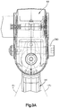
Fig. 3A is a top plan view of the first joint showing the angular range through which the second member can pivot relative to the first member; -
Fig. 3B is a top plan view of the second joint showing the angular range through which the third member can pivot relative to the first member; -
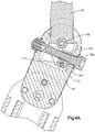
Fig. 4A is a cross-sectional view of the second joint shown inFig. 3B , the third member being in a first position relative to the second member. -
Fig. 4B is a cross-sectional view of the second joint shown inFig. 3B , the third member being in a second position relative to the second member; and -
Fig. 4C is a cross-sectional view of the second joint shown inFig. 3B , the third member being in a third position relative to the second member. - Referring to
Fig. 1 , a personal mobility vehicle, such as awheelchair 10, can include abase 14, and aseating system 18 attached to thebase 14. Thebase 14 can include aframe 22, a pair ofdrive wheels 26 coupled to theframe 22, and a pair of drives operatively coupled to thedrive wheels 26 such that the drives cause the wheels to rotate to thereby propel thewheelchair 10 in a desired direction. Theseating system 18 can include aseat base 34, aseat back 38, and a pair of adjustable arm supports 42 that are coupled to opposed sides of theseat back 38. Theadjustable arm supports 42 are configured to be easily adjusted to desired positions so as to accommodate different individuals. It should be appreciated, that the mechanisms disclosed can be incorporated into other portions of thewheelchair 10 and that the personal mobility vehicle can have other configurations. For example, the mechanisms that allow the adjustable arm supports 42 to be easily adjusted can be incorporated into leg supports of the wheelchair and the personal mobility vehicle can be configured as a scooter, as desired. - Certain terminology is used in the following description for convenience only and is not limiting. The words "right", "left", "lower" and "upper" designate directions in the drawings to which reference is made. The words "inner" or "distal" and "outer" or "proximal" refer to directions toward and away from, respectively, the geometric center of the implant and related parts thereof. The terminology includes the above-listed words, derivatives thereof and words of similar import.
- The
adjustable arm supports 42 are substantially identical. Therefore it should be appreciated, that while afirst arm support 42 of the pair ofadjustable arm supports 42 will be described, thesecond arm support 42 will include substantially similar components as thefirst arm support 42 and will operate in a substantially similar manner. Referring toFig. 2A , theadjustable arm support 42 is described herein as extending horizontally along a longitudinal direction "L" and lateral direction "A", and vertically along a transverse direction "T". Unless otherwise specified herein, the terms "lateral," "longitudinal," and "transverse" are used to describe the orthogonal directional components of various components. It should be appreciated, however, that the directional components of the various components of theadjustable arm support 42 will vary during use. For instance, while the longitudinal directional components of each component of thearm support 42 are parallel to each other inFig. 2A , when thearm support 42 is adjusted, the longitudinal directional component of one component of thearm support 42 may be angularly offset from that of a second component of thearm support 42. - As shown in
Figs. 2A and2B , theadjustable arm support 42 includes afirst member 50, asecond member 54 pivotally coupled to thefirst member 50 at afirst joint 58, and athird member 62 pivotally coupled to thesecond member 54 at asecond joint 66. Thefirst member 50 can be configured as a shoulder that is coupled to theseat back 38, thesecond member 54 can be configured as an upper arm portion, and thethird member 62 can be configured to support an arm rest. It should be appreciated, however, that the first, second, and third members can be any portion of theadjustable arm support 42 unless otherwise claimed. For example, in an embodiment where theadjustable arm support 42 includes a single adjustable portion, the upper arm portion may be considered the first member and the portion that supports the arm rest may be considered the second member or vice versa. Further, it should be appreciated, that the seat back 38 not only includes the portion that an individual rests against but also includes any structure that is supported by that portion. - As shown in
Fig. 2B , thefirst member 50 includes abody 68 that is elongate along a first direction, such as along the longitudinal direction. Thebody 68 can define afirst end 70 and asecond end 74 spaced from thefirst end 70 along the first direction. Thefirst end 70 defines afirst cavity 78 that extends into thebody 68 along the first direction. Thefirst member 50 can further include afirst attachment member 82 that extends through thefirst cavity 78 so as to define an axis A1 that extends along a second direction that is substantially perpendicular to the first direction, such as along the transverse direction. In particular, thefirst member 50 can define a pair ofbores 86 that are configured to receive thefirst attachment member 82 to thereby secure thefirst attachment member 82 to thebody 68. - The
first attachment member 82 can include a substantiallycylindrical body 90 that is elongate along the second direction and a pair offasteners 94 that are configured to be coupled to opposed ends of thebody 90 to thereby trap or otherwise couple thebody 90 to thefirst member 50. As shown, thecylindrical body 90 is configured to be received by thebores 86 and thefasteners 94 have a dimension that is greater than that of thebores 86 such that when thefasteners 94 are coupled to thebody 90, thebody 90 will be trapped within thebores 86. It should be appreciated, however, that thefirst attachment member 82 can have any configuration as desired. For example, thefirst attachment member 82 can be configured as a standard bolt, as desired. - With continued reference to
Figs. 2A and2B , thesecond member 54 can include anangled body member 102 that defines afirst end 106 and asecond end 110 that is spaced from the first end along the first direction. Theangled body member 102 extends between the first and second ends 106 and 110 such that thesecond end 110 of thesecond member 54 is offset from thefirst end 106 of thesecond member 54 along the second direction. Thefirst end 106 of the second member is configured to be disposed within thefirst cavity 78 such that the second member is pivotally attached to thefirst member 50 by thefirst attachment member 82. It should be appreciated, that while thesecond member 54 includes anangled body member 102 in the illustrated embodiment, thesecond member 54 can be substantially straight such that the first and second ends 106 and 110 are not offset from each other along the second direction. - As shown in
Fig. 2B , thefirst end 106 includes a first pair ofplates 114 that are spaced from each other along the second direction. Eachplate 114 defines arespective bore 118 such that when theplates 114 are received within thefirst cavity 78 thebores 118 align with thebores 86 and thefirst attachment member 82 extends through thebores second member 54 to thefirst member 50. As shown inFig. 2B , eachplate 114 further defines aslot 122 that is elongate along the first direction. As illustrated, eachslot 122 can be rearward from therespective bore 118 and can be aligned with therespective bore 118 along the first direction. It should be appreciated, however, that thefirst end 106 can have any configuration as desired. For example, one of theplates 114 can define aslot 122 while the other plate is void of theslot 122 as desired. - Similarly, the
second end 110 includes a second pair ofplates 124 that are spaced from each other along the second direction. Eachplate 124 defines arespective bore 128 and arespective slot 132 that is elongate along the first direction. As illustrated eachslot 132 can be forward of therespective bore 128 and can be aligned with therespective bore 128 along the first direction. It should be appreciated, however, that thesecond end 110 can have any configuration as desired. For example, one of theplates 124 can define aslot 132 while the other plate is void of theslot 132 as desired. - With continued reference to
Fig. 2B , thesecond member 54 further includes afirst nut 140 that is pivotally and translatably coupled between the first pair ofplates 114. Thenut 140 includes anut body 144 that defines anaperture 148 that extends through thebody 144 along a third direction that is perpendicular to at least the second direction, such as along the lateral direction. Theaperture 148 carries an internal thread that is configured to mate with an external thread of an actuator such that rotation of the actuator causes thenut 140 to move along the actuator along the third direction. Thenut 140 further includes a pair ofengagement members 152 that extend from thenut body 144 along the second direction such that eachengagement member 152 extends into arespective slot 122 of the first pair ofplates 114 to thereby pivotally and slidably couple thenut 140 to theplates 114. As illustrated, theengagement members 152 can be ends of a single rod that extends through thenut body 144 along the second direction. It should be appreciated, however, that theengagement members 152 can be separate members that extend from thebody 144 in opposite directions and are monolithic with thenut body 144. Theengagement members 152 can have a dimension that is substantially equal to the width of theslots 122. Therefore, in the illustrated embodiment, thenut 140 can only move along that first direction, and will be substantially translatably fixed in all other directions. - In the illustrated embodiment the
nut body 144 is elongate along the first direction and theaperture 148 is disposed forward relative to theengagement members 152. Thenut body 144 is pivotable relative to thefirst end 106 and can move or otherwise translate relative to thefirst end 106 along the first direction. It should be appreciate, however, that thenut 140 can have any configuration as desired. - As shown in
Fig. 2B , thesecond member 54 further includes asecond nut 160 that is pivotally and translatably coupled between the second pair ofplates 124. Thenut 160 includes anut body 164 that defines anaperture 168 that extends through thebody 164 along the third direction. Theaperture 168 carries an internal thread that is configured to mate with an external thread of an actuator such that rotation of the actuator causes thenut 160 to move along the actuator along the third direction. Thenut 160 further includes a pair ofengagement members 172 that extend from thenut body 164 along the second direction such that eachengagement member 172 extends into arespective slot 132 of the second pair ofplates 124. As illustrated, theengagement members 172 can be ends of a single rod that extends through thenut body 164 along the second direction. It should be appreciated, however, that the engagement members can be separate members that extend from thebody 164 in opposite directions and are monolithic with thenut body 164. Theengagement members 172 can have a dimension that is substantially equal to the width of theslots 132. Therefore, thenut 160 can only move along that first direction, and will be substantially translatably fixed in all other directions. - In the illustrated embodiment the
nut body 164 is elongate along the first direction and theaperture 168 is disposed rearward relative to theengagement members 172. Thenut body 164 is pivotable relative to thesecond end 110 and can move or otherwise translate relative thesecond end 110 along the first direction. - With continued reference to
Fig. 2B , thethird member 62 includes abody 180 that is elongate along the first direction Thebody 180 can define afirst end 184 and asecond end 188 spaced from thefirst end 184 along the first direction. Thefirst end 184 defines asecond cavity 192 that extends into thebody 180 along the first direction. Thethird member 62 can further include asecond attachment member 196 that extends through thesecond cavity 192 so as to define an axis A2 that extends along the second direction. In particular, thethird member 62 can define a pair ofbores 198 that are configured to receive thesecond attachment member 196 to thereby secure thesecond attachment member 196 to thebody 180. - The
second attachment member 196 can include a substantiallycylindrical body 200 that is elongate along the second direction, and a pair offasteners 204 that are configured to be coupled to opposed ends of thebody 200 to thereby trap or otherwise couple thebody 200 to thethird member 62. As shown, thecylindrical body 200 is configured to be received by thebores 198 and thefasteners 204 have a dimension that is greater than that of thebores 198 such that when thefasteners 204 are coupled to thebody 200, thebody 200 will be trapped within thebores 198. It should be appreciated, however, that thesecond attachment member 196 can have any configuration as desired. For example, thesecond attachment member 196 can be configured as a standard bolt. - As shown in
Figs. 2A and2B , theadjustable arm support 42 can further include anarm rest 214 that is supported by thesecond end 188 of thethird member 62. Thearm rest 214 is elongate along the first direction and is configured to support an infirmed persons arms in a comfortable position. - As shown in
Figs. 2A and2B , theadjustable arm support 42 can further include afirst actuator 280 that extends through thefirst end 106 of thesecond member 54 and through thefirst cavity 78 along the third direction, and asecond actuator 284 that extends through thesecond end 110 of thesecond member 54 and through thesecond cavity 192 along the third direction. Thefirst actuator 280 can be operatively coupled to thesecond member 54 such that actuation of thefirst actuator 280 causes thesecond member 54 to pivot about the axis A1 and thesecond actuator 284 can be operatively coupled to thesecond member 54 such that actuation of thesecond actuator 284 causes thethird member 62 to pivot about the axis A2. - The first and
second actuators respective bolts 296 that define external threads configured to mate with the internal threads of the first andsecond nuts bolt 296 can define amating interface 300 that is configured to receive a tool such as a wrench. When the wrench is engaged with one of the mating interfaces 300, rotation of the wrench will cause thebolt 296 to rotate thereby causing the nut to travel along thebolt 296. It should be appreciated, however, that the first andsecond actuators second actuators - Now in reference to
Figs. 3A-3B , thethird member 62 may be adjusted relative to thesecond member 54 by rotating thesecond actuator 284. It should be appreciated, that thesecond member 54 can also be rotated relative to thefirst member 50 in a similar manner if it is desired to adjust the angular position of thesecond member 54. As shown inFig. 3A , thesecond member 54 can be adjusted relative to thefirst member 50 to any desired angle θ1 within a specified angular range that is between about -A1 and about A1. For example, the second member can be adjusted relative to thefirst member 50 to any desired angle θ1 that is between about - 25° and about 25° relative to the longitudinal direction of thefirst member 50. Similarly, and as illustrated inFig. 3B , thethird member 62 can be adjusted relative to thesecond member 54 to any desired angle θ2 within a specified angular range that is between about -B1 and about B1. For example, the third member can be adjusted relative to thesecond member 54 to any desired angle θ2 that is between about - 25° and about 25° relative to the longitudinal direction of thesecond member 54. That is, rotation of theactuators second member 54 orthird member 62 to pivot to any desired angle within the specified angular range. It should be appreciated, however, that the desired ranges can be any ranges as desired. - In operation and as shown in
Figs. 4A-4C , the angular position of thethird member 62 can be adjusted by rotating thesecond actuator 284. As shown inFig. 4A , when thethird member 62 is in a first angular position, for example at -B1, theengagement members 172 of thenut 160 will be disposed in a first or forward portion of theslots 132 and thenut 160 will be positioned proximate to a first end of theactuator 284. As shown inFig. 4B , as thesecond actuator 284 is rotated, thenut 160 will move along thesecond actuator 284 toward the middle of theactuator 284 while theengagement members 172 move toward a second or rearward portion of theslots 132. InFig. 4B , thethird member 62 is shown in a second position whereby by the angular position of thethird member 62 is 0°. As shown inFig. 4C , thethird member 62 can be moved toward a third angular position, for example at B1. In such a position, theengagement members 172 of thenut 160 will once again be disposed in the first or forward portion of theslots 132 and thenut 160 will be positioned proximate to a second end of theactuator 284. Because thenut 160 is able to pivot and translate relative to thesecond member 54, thenut 160 is able to move along thesecond actuator 284 when theactuator 284 is rotated to thereby cause thethird member 62 to pivot relative to thesecond member 54. - The
second member 54 can be adjusted in a similar manner as thethird member 62. Depending on the position of thefirst nut 140, however, theengagement members 152 of thefirst nut 140 may be in a rearward portion of theslots 122 when thesecond member 54 is at an angular position of 0° relative to thefirst member 50. - While the foregoing description and drawings represent the preferred embodiments of the present invention, it will be understood that various additions, modifications, combinations and/or substitutions may be made therein without departing from the spirit and scope of the invention as defined in the accompanying claims. In particular, it will be clear to those skilled in the art that the invention may be embodied in other specific forms, structures, arrangements, proportions, and with other elements, materials, and components, without departing from the spirit or essential characteristics thereof. One skilled in the art will appreciate that the invention may be used with many modifications of structure, arrangement, proportions, materials, and components, which are particularly adapted to specific environments and operative requirements without departing from the principles of the invention. In addition, features described herein may be used singularly or in combination with other features. For example, features described in connection with one embodiment may be used and/or interchanged with features described in another embodiment. The presently disclosed embodiments are therefore to be considered in all respects as illustrative and not restrictive, the scope of the invention being defined by the appended claims, and not limited to the foregoing description.
- It will be appreciated by those skilled in the art that various modifications and alterations of the invention can be made without departing from the broad scope of the appended claims. Some of these have been discussed above and others will be apparent to those skilled in the art.
Claims (10)
- An arm support (42) for a wheelchair (10), the arm support comprising:a first support member (50) including a first end (70) and a second end (74) spaced from the first end along a first direction, the first end defining a first cavity (78), and the first support memberfurther including a first attachment member (82) that extends through the first cavity so as to define an axis that extends along a second direction that is substantially perpendicular to the first direction, characterised in that the arm support further comprisesa second support member (54) having a first end (106) and a second end (110) spaced from the first end along the first direction, the second support member including an angled body member (102) that extends between first and second ends of the second support member such that the second end of the second support member is offset from the first end of the second support member along the second direction, the first end of the second support member being disposed within the first cavity (78) such that the second support member is pivotally attached to the first support member by the first attachment member; andan actuator (280) that extends through the first end (106) of the second support member (54) and through the first cavity (78) along a third direction that is substantially perpendicular to at least the second direction, the actuator (280) being operatively coupled to the second support member such that actuation of the actuator causes the second support member to pivot about the axis.
- The arm support (42) of claim 1, wherein the first end of the second support member includes a pair of plates (114) that are spaced from each other along the second direction.
- The arm support (42) of claim 2, wherein the first attachment member (82) extends through the pair of plates (114) along the second direction.
- The arm support (42) of claim 2, wherein the second support member further includes a nut (140) that is pivotally coupled between the pair of plates (114), the nut including aperture (148) that carries a thread, the actuator defining a bolt that carries a thread that mates with the thread of the nut such that rotation of the bolt causes the nut to move along the bolt along the third direction.
- The arm support (42) of claim 4, wherein each plate of the pair of plates defines a slot (122) that is elongate along the first direction, and wherein the nut (140) includes a body (144) that defines the aperture (148), and the nut further includes a pair of engagement members (152) that extend from the body along the second direction such that each engagement member extends into a respective slot of the pair of plates.
- The arm support (42) of claim 5, wherein the nut (140) moves along the first direction relative to the second member as the nut moves along the bolt.
- The arm support (42) of claim 1, wherein the first support member (50) is a shoulder support member that is coupled to a wheelchair seat back and the second support member (54) is an upper arm support portion that includes the angled body member that extends between the first and second ends such that the second end of the upper arm support portion is offset from the first end of the upper arm support portion along the second direction.
- The arm support (42) of claim 7, further comprising a third support member (62) having a first end (184) and a second end (188) spaced from the first end along the first direction, the first end of the third support member defining a second cavity (194), and the third support member including a second attachment member (196) that extends through the second cavity so as to define an axis that extends along the second direction, wherein the second end of the second support member (54) is disposed within the second cavity such that the second support member is pivotally attached to the third support member by the second attachment member.
- The arm support (42) of claim 8, wherein the actuator (280) is a first actuator (280), and the arm support (42) further comprises a second actuator (284) that extends through the second end (110) of the second support member (54) and through the second cavity (192), the second actuator being operatively coupled to the second support member such that actuation of the second actuator causes the third support member to pivot about the axis of the second attachment member.
- The arm support (42) of claim 9, further comprising an arm rest that is supported by the second end (188) of the third member (62).
Applications Claiming Priority (2)
| Application Number | Priority Date | Filing Date | Title |
|---|---|---|---|
| US201361779139P | 2013-03-13 | 2013-03-13 | |
| PCT/US2014/020976 WO2014158935A1 (en) | 2013-03-13 | 2014-03-06 | Adjustable limb support for personal mobility vehicles |
Publications (2)
| Publication Number | Publication Date |
|---|---|
| EP2968042A1 EP2968042A1 (en) | 2016-01-20 |
| EP2968042B1 true EP2968042B1 (en) | 2018-11-14 |
Family
ID=50349937
Family Applications (1)
| Application Number | Title | Priority Date | Filing Date |
|---|---|---|---|
| EP14712490.3A Active EP2968042B1 (en) | 2013-03-13 | 2014-03-06 | Adjustable limb support for personal mobility vehicles |
Country Status (6)
| Country | Link |
|---|---|
| US (1) | US9427364B2 (en) |
| EP (1) | EP2968042B1 (en) |
| AU (1) | AU2014241778A1 (en) |
| CA (1) | CA2906422C (en) |
| ES (1) | ES2701228T3 (en) |
| WO (1) | WO2014158935A1 (en) |
Families Citing this family (13)
| Publication number | Priority date | Publication date | Assignee | Title |
|---|---|---|---|---|
| JP5918232B2 (en) * | 2010-07-08 | 2016-05-18 | サウスコ,インコーポレイティド | Display support device |
| CA151012S (en) * | 2012-11-12 | 2014-02-20 | Roger Thomas Mascull | Backrest |
| US9427364B2 (en) * | 2013-03-13 | 2016-08-30 | Pride Mobility Products Corporation | Adjustable limb support for personal mobility vehicles |
| US10264884B2 (en) * | 2014-08-18 | 2019-04-23 | Aaron DeJule | Sitting apparatus |
| US9717637B2 (en) * | 2014-10-08 | 2017-08-01 | Adaptive Engineering Lab, Inc. | Lateral support assembly |
| US11131423B2 (en) | 2016-03-07 | 2021-09-28 | Southco, Inc. | Display support arm assembly for mounting a display |
| CA3033015C (en) * | 2018-02-12 | 2023-02-07 | Midmark Corporation | Arm rest assembly for examination table |
| US11235820B2 (en) | 2018-03-14 | 2022-02-01 | Treker Mobility Llc | Adaptive track assembly |
| JP7205760B2 (en) * | 2019-01-31 | 2023-01-17 | スズキ株式会社 | moving body |
| CA3168572C (en) | 2022-07-13 | 2025-08-05 | Invacare Corporation | Wheelchair and suspension systems |
| USD1033279S1 (en) | 2022-08-22 | 2024-07-02 | Three Oceans, LLC | Scooter |
| US12377915B1 (en) * | 2023-06-23 | 2025-08-05 | Brent Henry Foes | Camber adjustment system |
| CA230079S (en) * | 2023-10-10 | 2025-12-11 | Lifebloom | WHEELCHAIR FOR THE DISABLED |
Citations (1)
| Publication number | Priority date | Publication date | Assignee | Title |
|---|---|---|---|---|
| US20080201851A1 (en) * | 1999-12-29 | 2008-08-28 | Menkedick Douglas J | Lift system for hospital bed |
Family Cites Families (13)
| Publication number | Priority date | Publication date | Assignee | Title |
|---|---|---|---|---|
| GB1368134A (en) * | 1971-09-28 | 1974-09-25 | Keropian M | Trunk support for sitting patients |
| US4687167A (en) * | 1985-10-23 | 1987-08-18 | Skalka Gerald P | Multi-position computer support |
| US6378947B1 (en) | 1999-04-12 | 2002-04-30 | Bloorview Macmillan Centre | Seating system |
| US6322145B1 (en) | 1999-04-27 | 2001-11-27 | Freedom Designs, Inc. | Wheelchair seat back with adjustable tilt |
| US6478274B1 (en) * | 1999-05-10 | 2002-11-12 | Innovative Office Products, Inc. | Arm apparatus for mounting electronic devices |
| US6347771B1 (en) * | 1999-06-11 | 2002-02-19 | Pierre Lauzon | Portable arm and mouse support for use with personal computers |
| US6619747B2 (en) * | 2001-04-25 | 2003-09-16 | Kam Ko | Torso and forearm supporting device for chairs and workstands |
| US7222826B1 (en) * | 2002-11-23 | 2007-05-29 | Andrew Berglund | Adaptive arm support |
| DE10349019B3 (en) | 2003-10-13 | 2005-06-23 | Invacare (Deutschland) Gmbh | wheelchair |
| SE527730C2 (en) * | 2004-10-07 | 2006-05-23 | Volvo Constr Equip Holding Se | Foldable armrest for a vehicle seat |
| WO2006132938A2 (en) * | 2005-06-03 | 2006-12-14 | Steel Case Development Corporation | Support arm assembly |
| US8469323B1 (en) * | 2008-04-21 | 2013-06-25 | Yani Deros | Modular monitor support assembly |
| US9427364B2 (en) * | 2013-03-13 | 2016-08-30 | Pride Mobility Products Corporation | Adjustable limb support for personal mobility vehicles |
-
2014
- 2014-03-06 US US14/199,025 patent/US9427364B2/en not_active Expired - Fee Related
- 2014-03-06 EP EP14712490.3A patent/EP2968042B1/en active Active
- 2014-03-06 CA CA2906422A patent/CA2906422C/en active Active
- 2014-03-06 AU AU2014241778A patent/AU2014241778A1/en not_active Abandoned
- 2014-03-06 WO PCT/US2014/020976 patent/WO2014158935A1/en not_active Ceased
- 2014-03-06 ES ES14712490T patent/ES2701228T3/en active Active
Patent Citations (1)
| Publication number | Priority date | Publication date | Assignee | Title |
|---|---|---|---|---|
| US20080201851A1 (en) * | 1999-12-29 | 2008-08-28 | Menkedick Douglas J | Lift system for hospital bed |
Also Published As
| Publication number | Publication date |
|---|---|
| US9427364B2 (en) | 2016-08-30 |
| CA2906422C (en) | 2021-03-23 |
| AU2014241778A1 (en) | 2015-11-05 |
| ES2701228T3 (en) | 2019-02-21 |
| CA2906422A1 (en) | 2014-10-02 |
| EP2968042A1 (en) | 2016-01-20 |
| WO2014158935A1 (en) | 2014-10-02 |
| US20140265508A1 (en) | 2014-09-18 |
Similar Documents
| Publication | Publication Date | Title |
|---|---|---|
| US9427364B2 (en) | Adjustable limb support for personal mobility vehicles | |
| US10182953B2 (en) | Wheelchair backrest mounting system | |
| EP2595507B1 (en) | Seat device for supporting a sitting person | |
| CN101795892B (en) | vehicle headrest | |
| US10589642B2 (en) | Easy-entry vehicle seat | |
| EP2740456B2 (en) | Wheelchair backrest assembly | |
| WO2014138128A1 (en) | Tilt-in-space wheelchair using multiple controlling paths | |
| US20230270255A1 (en) | Double angle back support adjustment | |
| US20190060144A1 (en) | Mid-wheel tilt-in-space manual wheelchair with constant shoulder position | |
| US6131940A (en) | Tilt-in-space wheelchair | |
| WO2002065970A1 (en) | Adjustable seat frame | |
| CN104245412B (en) | Longitudinal adjusting mechanism suitable for seat, mechanism and seat suitable for adjusting seat portion gradient | |
| JP2020529896A5 (en) | ||
| EP2913038B1 (en) | Wheelchair backrest having position adjustment | |
| EP2709491B1 (en) | Lateral support apparatus for a chair | |
| EP3459395B1 (en) | Seating and/or lounging furniture | |
| WO2017219036A1 (en) | Reversible seating mechanism with tilt limiting device | |
| CN113853144A (en) | Rotary connecting structure of nursing device | |
| EP0608964B1 (en) | Reclining seat back assembly for a wheelchair | |
| EP3458008B1 (en) | Device for securing an arm support structure | |
| JPH01214308A (en) | Reclining seat | |
| US12599521B2 (en) | Adjustment device for removably coupling a seatback to a seat | |
| JP7137665B1 (en) | assistive device | |
| SK9442003A3 (en) | Clamping device for controlling rotation of a chair about a support shaft of a base frame | |
| CN202272047U (en) | Locking mechanism of automobile steering column |
Legal Events
| Date | Code | Title | Description |
|---|---|---|---|
| PUAI | Public reference made under article 153(3) epc to a published international application that has entered the european phase |
Free format text: ORIGINAL CODE: 0009012 |
|
| 17P | Request for examination filed |
Effective date: 20151012 |
|
| AK | Designated contracting states |
Kind code of ref document: A1 Designated state(s): AL AT BE BG CH CY CZ DE DK EE ES FI FR GB GR HR HU IE IS IT LI LT LU LV MC MK MT NL NO PL PT RO RS SE SI SK SM TR |
|
| AX | Request for extension of the european patent |
Extension state: BA ME |
|
| DAX | Request for extension of the european patent (deleted) | ||
| STAA | Information on the status of an ep patent application or granted ep patent |
Free format text: STATUS: EXAMINATION IS IN PROGRESS |
|
| 17Q | First examination report despatched |
Effective date: 20170502 |
|
| GRAP | Despatch of communication of intention to grant a patent |
Free format text: ORIGINAL CODE: EPIDOSNIGR1 |
|
| STAA | Information on the status of an ep patent application or granted ep patent |
Free format text: STATUS: GRANT OF PATENT IS INTENDED |
|
| INTG | Intention to grant announced |
Effective date: 20180528 |
|
| GRAS | Grant fee paid |
Free format text: ORIGINAL CODE: EPIDOSNIGR3 |
|
| GRAA | (expected) grant |
Free format text: ORIGINAL CODE: 0009210 |
|
| STAA | Information on the status of an ep patent application or granted ep patent |
Free format text: STATUS: THE PATENT HAS BEEN GRANTED |
|
| AK | Designated contracting states |
Kind code of ref document: B1 Designated state(s): AL AT BE BG CH CY CZ DE DK EE ES FI FR GB GR HR HU IE IS IT LI LT LU LV MC MK MT NL NO PL PT RO RS SE SI SK SM TR |
|
| REG | Reference to a national code |
Ref country code: CH Ref legal event code: EP Ref country code: AT Ref legal event code: REF Ref document number: 1063936 Country of ref document: AT Kind code of ref document: T Effective date: 20181115 |
|
| REG | Reference to a national code |
Ref country code: DE Ref legal event code: R096 Ref document number: 602014035963 Country of ref document: DE |
|
| REG | Reference to a national code |
Ref country code: IE Ref legal event code: FG4D |
|
| REG | Reference to a national code |
Ref country code: NL Ref legal event code: FP |
|
| REG | Reference to a national code |
Ref country code: ES Ref legal event code: FG2A Ref document number: 2701228 Country of ref document: ES Kind code of ref document: T3 Effective date: 20190221 |
|
| REG | Reference to a national code |
Ref country code: LT Ref legal event code: MG4D |
|
| REG | Reference to a national code |
Ref country code: AT Ref legal event code: MK05 Ref document number: 1063936 Country of ref document: AT Kind code of ref document: T Effective date: 20181114 |
|
| PG25 | Lapsed in a contracting state [announced via postgrant information from national office to epo] |
Ref country code: FI Free format text: LAPSE BECAUSE OF FAILURE TO SUBMIT A TRANSLATION OF THE DESCRIPTION OR TO PAY THE FEE WITHIN THE PRESCRIBED TIME-LIMIT Effective date: 20181114 Ref country code: NO Free format text: LAPSE BECAUSE OF FAILURE TO SUBMIT A TRANSLATION OF THE DESCRIPTION OR TO PAY THE FEE WITHIN THE PRESCRIBED TIME-LIMIT Effective date: 20190214 Ref country code: IS Free format text: LAPSE BECAUSE OF FAILURE TO SUBMIT A TRANSLATION OF THE DESCRIPTION OR TO PAY THE FEE WITHIN THE PRESCRIBED TIME-LIMIT Effective date: 20190314 Ref country code: AT Free format text: LAPSE BECAUSE OF FAILURE TO SUBMIT A TRANSLATION OF THE DESCRIPTION OR TO PAY THE FEE WITHIN THE PRESCRIBED TIME-LIMIT Effective date: 20181114 Ref country code: LV Free format text: LAPSE BECAUSE OF FAILURE TO SUBMIT A TRANSLATION OF THE DESCRIPTION OR TO PAY THE FEE WITHIN THE PRESCRIBED TIME-LIMIT Effective date: 20181114 Ref country code: HR Free format text: LAPSE BECAUSE OF FAILURE TO SUBMIT A TRANSLATION OF THE DESCRIPTION OR TO PAY THE FEE WITHIN THE PRESCRIBED TIME-LIMIT Effective date: 20181114 Ref country code: LT Free format text: LAPSE BECAUSE OF FAILURE TO SUBMIT A TRANSLATION OF THE DESCRIPTION OR TO PAY THE FEE WITHIN THE PRESCRIBED TIME-LIMIT Effective date: 20181114 Ref country code: BG Free format text: LAPSE BECAUSE OF FAILURE TO SUBMIT A TRANSLATION OF THE DESCRIPTION OR TO PAY THE FEE WITHIN THE PRESCRIBED TIME-LIMIT Effective date: 20190214 |
|
| PG25 | Lapsed in a contracting state [announced via postgrant information from national office to epo] |
Ref country code: AL Free format text: LAPSE BECAUSE OF FAILURE TO SUBMIT A TRANSLATION OF THE DESCRIPTION OR TO PAY THE FEE WITHIN THE PRESCRIBED TIME-LIMIT Effective date: 20181114 Ref country code: PT Free format text: LAPSE BECAUSE OF FAILURE TO SUBMIT A TRANSLATION OF THE DESCRIPTION OR TO PAY THE FEE WITHIN THE PRESCRIBED TIME-LIMIT Effective date: 20190314 Ref country code: RS Free format text: LAPSE BECAUSE OF FAILURE TO SUBMIT A TRANSLATION OF THE DESCRIPTION OR TO PAY THE FEE WITHIN THE PRESCRIBED TIME-LIMIT Effective date: 20181114 Ref country code: GR Free format text: LAPSE BECAUSE OF FAILURE TO SUBMIT A TRANSLATION OF THE DESCRIPTION OR TO PAY THE FEE WITHIN THE PRESCRIBED TIME-LIMIT Effective date: 20190215 Ref country code: SE Free format text: LAPSE BECAUSE OF FAILURE TO SUBMIT A TRANSLATION OF THE DESCRIPTION OR TO PAY THE FEE WITHIN THE PRESCRIBED TIME-LIMIT Effective date: 20181114 |
|
| PG25 | Lapsed in a contracting state [announced via postgrant information from national office to epo] |
Ref country code: CZ Free format text: LAPSE BECAUSE OF FAILURE TO SUBMIT A TRANSLATION OF THE DESCRIPTION OR TO PAY THE FEE WITHIN THE PRESCRIBED TIME-LIMIT Effective date: 20181114 Ref country code: PL Free format text: LAPSE BECAUSE OF FAILURE TO SUBMIT A TRANSLATION OF THE DESCRIPTION OR TO PAY THE FEE WITHIN THE PRESCRIBED TIME-LIMIT Effective date: 20181114 Ref country code: DK Free format text: LAPSE BECAUSE OF FAILURE TO SUBMIT A TRANSLATION OF THE DESCRIPTION OR TO PAY THE FEE WITHIN THE PRESCRIBED TIME-LIMIT Effective date: 20181114 |
|
| REG | Reference to a national code |
Ref country code: DE Ref legal event code: R097 Ref document number: 602014035963 Country of ref document: DE |
|
| PG25 | Lapsed in a contracting state [announced via postgrant information from national office to epo] |
Ref country code: SM Free format text: LAPSE BECAUSE OF FAILURE TO SUBMIT A TRANSLATION OF THE DESCRIPTION OR TO PAY THE FEE WITHIN THE PRESCRIBED TIME-LIMIT Effective date: 20181114 Ref country code: EE Free format text: LAPSE BECAUSE OF FAILURE TO SUBMIT A TRANSLATION OF THE DESCRIPTION OR TO PAY THE FEE WITHIN THE PRESCRIBED TIME-LIMIT Effective date: 20181114 Ref country code: RO Free format text: LAPSE BECAUSE OF FAILURE TO SUBMIT A TRANSLATION OF THE DESCRIPTION OR TO PAY THE FEE WITHIN THE PRESCRIBED TIME-LIMIT Effective date: 20181114 Ref country code: SK Free format text: LAPSE BECAUSE OF FAILURE TO SUBMIT A TRANSLATION OF THE DESCRIPTION OR TO PAY THE FEE WITHIN THE PRESCRIBED TIME-LIMIT Effective date: 20181114 |
|
| PLBE | No opposition filed within time limit |
Free format text: ORIGINAL CODE: 0009261 |
|
| STAA | Information on the status of an ep patent application or granted ep patent |
Free format text: STATUS: NO OPPOSITION FILED WITHIN TIME LIMIT |
|
| REG | Reference to a national code |
Ref country code: DE Ref legal event code: R119 Ref document number: 602014035963 Country of ref document: DE |
|
| 26N | No opposition filed |
Effective date: 20190815 |
|
| PG25 | Lapsed in a contracting state [announced via postgrant information from national office to epo] |
Ref country code: MC Free format text: LAPSE BECAUSE OF FAILURE TO SUBMIT A TRANSLATION OF THE DESCRIPTION OR TO PAY THE FEE WITHIN THE PRESCRIBED TIME-LIMIT Effective date: 20181114 Ref country code: SI Free format text: LAPSE BECAUSE OF FAILURE TO SUBMIT A TRANSLATION OF THE DESCRIPTION OR TO PAY THE FEE WITHIN THE PRESCRIBED TIME-LIMIT Effective date: 20181114 |
|
| REG | Reference to a national code |
Ref country code: CH Ref legal event code: PL |
|
| REG | Reference to a national code |
Ref country code: NL Ref legal event code: MM Effective date: 20190401 |
|
| PG25 | Lapsed in a contracting state [announced via postgrant information from national office to epo] |
Ref country code: LU Free format text: LAPSE BECAUSE OF NON-PAYMENT OF DUE FEES Effective date: 20190306 |
|
| REG | Reference to a national code |
Ref country code: BE Ref legal event code: MM Effective date: 20190331 |
|
| PG25 | Lapsed in a contracting state [announced via postgrant information from national office to epo] |
Ref country code: NL Free format text: LAPSE BECAUSE OF NON-PAYMENT OF DUE FEES Effective date: 20190401 Ref country code: IE Free format text: LAPSE BECAUSE OF NON-PAYMENT OF DUE FEES Effective date: 20190306 Ref country code: CH Free format text: LAPSE BECAUSE OF NON-PAYMENT OF DUE FEES Effective date: 20190331 Ref country code: LI Free format text: LAPSE BECAUSE OF NON-PAYMENT OF DUE FEES Effective date: 20190331 Ref country code: DE Free format text: LAPSE BECAUSE OF NON-PAYMENT OF DUE FEES Effective date: 20191001 |
|
| PG25 | Lapsed in a contracting state [announced via postgrant information from national office to epo] |
Ref country code: IT Free format text: LAPSE BECAUSE OF NON-PAYMENT OF DUE FEES Effective date: 20190306 Ref country code: FR Free format text: LAPSE BECAUSE OF NON-PAYMENT OF DUE FEES Effective date: 20190331 Ref country code: BE Free format text: LAPSE BECAUSE OF NON-PAYMENT OF DUE FEES Effective date: 20190331 |
|
| PG25 | Lapsed in a contracting state [announced via postgrant information from national office to epo] |
Ref country code: TR Free format text: LAPSE BECAUSE OF FAILURE TO SUBMIT A TRANSLATION OF THE DESCRIPTION OR TO PAY THE FEE WITHIN THE PRESCRIBED TIME-LIMIT Effective date: 20181114 |
|
| PG25 | Lapsed in a contracting state [announced via postgrant information from national office to epo] |
Ref country code: MT Free format text: LAPSE BECAUSE OF NON-PAYMENT OF DUE FEES Effective date: 20190306 |
|
| REG | Reference to a national code |
Ref country code: ES Ref legal event code: FD2A Effective date: 20200724 |
|
| PG25 | Lapsed in a contracting state [announced via postgrant information from national office to epo] |
Ref country code: ES Free format text: LAPSE BECAUSE OF NON-PAYMENT OF DUE FEES Effective date: 20190307 |
|
| PG25 | Lapsed in a contracting state [announced via postgrant information from national office to epo] |
Ref country code: CY Free format text: LAPSE BECAUSE OF FAILURE TO SUBMIT A TRANSLATION OF THE DESCRIPTION OR TO PAY THE FEE WITHIN THE PRESCRIBED TIME-LIMIT Effective date: 20181114 |
|
| PG25 | Lapsed in a contracting state [announced via postgrant information from national office to epo] |
Ref country code: HU Free format text: LAPSE BECAUSE OF FAILURE TO SUBMIT A TRANSLATION OF THE DESCRIPTION OR TO PAY THE FEE WITHIN THE PRESCRIBED TIME-LIMIT; INVALID AB INITIO Effective date: 20140306 |
|
| PG25 | Lapsed in a contracting state [announced via postgrant information from national office to epo] |
Ref country code: MK Free format text: LAPSE BECAUSE OF FAILURE TO SUBMIT A TRANSLATION OF THE DESCRIPTION OR TO PAY THE FEE WITHIN THE PRESCRIBED TIME-LIMIT Effective date: 20181114 |
|
| P01 | Opt-out of the competence of the unified patent court (upc) registered |
Effective date: 20230531 |
|
| PGFP | Annual fee paid to national office [announced via postgrant information from national office to epo] |
Ref country code: GB Payment date: 20250522 Year of fee payment: 12 |