EP2967660B1 - Patient-specific assemblies, jigs, and methods for a personalized total hip arthroplasty system - Google Patents
Patient-specific assemblies, jigs, and methods for a personalized total hip arthroplasty system Download PDFInfo
- Publication number
- EP2967660B1 EP2967660B1 EP14775248.9A EP14775248A EP2967660B1 EP 2967660 B1 EP2967660 B1 EP 2967660B1 EP 14775248 A EP14775248 A EP 14775248A EP 2967660 B1 EP2967660 B1 EP 2967660B1
- Authority
- EP
- European Patent Office
- Prior art keywords
- jig
- patient
- acetabular
- pin
- specific
- Prior art date
- Legal status (The legal status is an assumption and is not a legal conclusion. Google has not performed a legal analysis and makes no representation as to the accuracy of the status listed.)
- Active
Links
Images





Classifications
-
- A—HUMAN NECESSITIES
- A61—MEDICAL OR VETERINARY SCIENCE; HYGIENE
- A61B—DIAGNOSIS; SURGERY; IDENTIFICATION
- A61B17/00—Surgical instruments, devices or methods
- A61B17/16—Instruments for performing osteoclasis; Drills or chisels for bones; Trepans
- A61B17/17—Guides or aligning means for drills, mills, pins or wires
- A61B17/1739—Guides or aligning means for drills, mills, pins or wires specially adapted for particular parts of the body
- A61B17/1742—Guides or aligning means for drills, mills, pins or wires specially adapted for particular parts of the body for the hip
- A61B17/1746—Guides or aligning means for drills, mills, pins or wires specially adapted for particular parts of the body for the hip for the acetabulum
-
- A—HUMAN NECESSITIES
- A61—MEDICAL OR VETERINARY SCIENCE; HYGIENE
- A61B—DIAGNOSIS; SURGERY; IDENTIFICATION
- A61B17/00—Surgical instruments, devices or methods
- A61B17/14—Surgical saws
- A61B17/15—Guides therefor
-
- A—HUMAN NECESSITIES
- A61—MEDICAL OR VETERINARY SCIENCE; HYGIENE
- A61B—DIAGNOSIS; SURGERY; IDENTIFICATION
- A61B17/00—Surgical instruments, devices or methods
- A61B17/16—Instruments for performing osteoclasis; Drills or chisels for bones; Trepans
- A61B17/17—Guides or aligning means for drills, mills, pins or wires
- A61B17/1739—Guides or aligning means for drills, mills, pins or wires specially adapted for particular parts of the body
- A61B17/1742—Guides or aligning means for drills, mills, pins or wires specially adapted for particular parts of the body for the hip
- A61B17/175—Guides or aligning means for drills, mills, pins or wires specially adapted for particular parts of the body for the hip for preparing the femur for hip prosthesis insertion
-
- A—HUMAN NECESSITIES
- A61—MEDICAL OR VETERINARY SCIENCE; HYGIENE
- A61F—FILTERS IMPLANTABLE INTO BLOOD VESSELS; PROSTHESES; DEVICES PROVIDING PATENCY TO, OR PREVENTING COLLAPSING OF, TUBULAR STRUCTURES OF THE BODY, e.g. STENTS; ORTHOPAEDIC, NURSING OR CONTRACEPTIVE DEVICES; FOMENTATION; TREATMENT OR PROTECTION OF EYES OR EARS; BANDAGES, DRESSINGS OR ABSORBENT PADS; FIRST-AID KITS
- A61F2/00—Filters implantable into blood vessels; Prostheses, i.e. artificial substitutes or replacements for parts of the body; Appliances for connecting them with the body; Devices providing patency to, or preventing collapsing of, tubular structures of the body, e.g. stents
- A61F2/02—Prostheses implantable into the body
- A61F2/30—Joints
- A61F2/46—Special tools for implanting artificial joints
- A61F2/4603—Special tools for implanting artificial joints for insertion or extraction of endoprosthetic joints or of accessories thereof
- A61F2/4609—Special tools for implanting artificial joints for insertion or extraction of endoprosthetic joints or of accessories thereof of acetabular cups
-
- A—HUMAN NECESSITIES
- A61—MEDICAL OR VETERINARY SCIENCE; HYGIENE
- A61B—DIAGNOSIS; SURGERY; IDENTIFICATION
- A61B17/00—Surgical instruments, devices or methods
- A61B17/56—Surgical instruments or methods for treatment of bones or joints; Devices specially adapted therefor
- A61B2017/568—Surgical instruments or methods for treatment of bones or joints; Devices specially adapted therefor produced with shape and dimensions specific for an individual patient
-
- A—HUMAN NECESSITIES
- A61—MEDICAL OR VETERINARY SCIENCE; HYGIENE
- A61B—DIAGNOSIS; SURGERY; IDENTIFICATION
- A61B90/00—Instruments, implements or accessories specially adapted for surgery or diagnosis and not covered by any of the groups A61B1/00 - A61B50/00, e.g. for luxation treatment or for protecting wound edges
- A61B90/03—Automatic limiting or abutting means, e.g. for safety
- A61B2090/033—Abutting means, stops, e.g. abutting on tissue or skin
- A61B2090/034—Abutting means, stops, e.g. abutting on tissue or skin abutting on parts of the device itself
-
- A—HUMAN NECESSITIES
- A61—MEDICAL OR VETERINARY SCIENCE; HYGIENE
- A61F—FILTERS IMPLANTABLE INTO BLOOD VESSELS; PROSTHESES; DEVICES PROVIDING PATENCY TO, OR PREVENTING COLLAPSING OF, TUBULAR STRUCTURES OF THE BODY, e.g. STENTS; ORTHOPAEDIC, NURSING OR CONTRACEPTIVE DEVICES; FOMENTATION; TREATMENT OR PROTECTION OF EYES OR EARS; BANDAGES, DRESSINGS OR ABSORBENT PADS; FIRST-AID KITS
- A61F2/00—Filters implantable into blood vessels; Prostheses, i.e. artificial substitutes or replacements for parts of the body; Appliances for connecting them with the body; Devices providing patency to, or preventing collapsing of, tubular structures of the body, e.g. stents
- A61F2/02—Prostheses implantable into the body
- A61F2/30—Joints
- A61F2/32—Joints for the hip
- A61F2/34—Acetabular cups
- A61F2002/3401—Acetabular cups with radial apertures, e.g. radial bores for receiving fixation screws
-
- A—HUMAN NECESSITIES
- A61—MEDICAL OR VETERINARY SCIENCE; HYGIENE
- A61F—FILTERS IMPLANTABLE INTO BLOOD VESSELS; PROSTHESES; DEVICES PROVIDING PATENCY TO, OR PREVENTING COLLAPSING OF, TUBULAR STRUCTURES OF THE BODY, e.g. STENTS; ORTHOPAEDIC, NURSING OR CONTRACEPTIVE DEVICES; FOMENTATION; TREATMENT OR PROTECTION OF EYES OR EARS; BANDAGES, DRESSINGS OR ABSORBENT PADS; FIRST-AID KITS
- A61F2/00—Filters implantable into blood vessels; Prostheses, i.e. artificial substitutes or replacements for parts of the body; Appliances for connecting them with the body; Devices providing patency to, or preventing collapsing of, tubular structures of the body, e.g. stents
- A61F2/02—Prostheses implantable into the body
- A61F2/30—Joints
- A61F2/46—Special tools for implanting artificial joints
- A61F2002/4687—Mechanical guides for implantation instruments
-
- Y—GENERAL TAGGING OF NEW TECHNOLOGICAL DEVELOPMENTS; GENERAL TAGGING OF CROSS-SECTIONAL TECHNOLOGIES SPANNING OVER SEVERAL SECTIONS OF THE IPC; TECHNICAL SUBJECTS COVERED BY FORMER USPC CROSS-REFERENCE ART COLLECTIONS [XRACs] AND DIGESTS
- Y10—TECHNICAL SUBJECTS COVERED BY FORMER USPC
- Y10T—TECHNICAL SUBJECTS COVERED BY FORMER US CLASSIFICATION
- Y10T29/00—Metal working
- Y10T29/49—Method of mechanical manufacture
- Y10T29/49826—Assembling or joining
Definitions
- the present invention relates to a personalized total hip arthroplasty system. More particularly, the invention relates to patient-specific acetabular reaming and impacting jigs, and femoral resection and version jigs fabricated pre-operatively according to models generated via computer-assisted design based on imaging data derived from a specific patient.
- THA Total hip arthroplasty
- Improper placement and alignment of the acetabular implant cup caused by misaligned reaming results in higher failure rates.
- the femoral stem must be implanted at a precise depth and angle, and with an appropriate neck length to maintain normal kinematics.
- a surgical reamer is used to clear articular cartilage, tissue, and bone from the acetabulum to create an implantation site for the acetabular cup implant.
- the location and angle at which the reaming is done determines the final location and angulation of the implant.
- the surgeon estimates the angulation based off of pre-operative templating and intra-operative x-rays. The surgeon must also estimate angulation in this way when impacting the implant into the cup.
- total hip arthroplasty is a much more challenging procedure involving integration of data from several anatomical planes and axes relating to implantation of prosthetics into disengaged ball-in-socket joint structures and then re-approximation of the implanted joint parts to form an integrated operational ball-in-socket joint with precise implant geometry.
- pre-operative imaging and CAD has not been applied to achieve a complete operational patient-specific THA system.
- US 2011/224674 A1 describes an acetabular device including a patient-specific acetabular alignment guide with a bone engagement surface.
- the bone engagement surface has a first portion configured and shaped to be conforming and complementary to an acetabular rim surface and a second portion configured and shaped to be conforming and complementary to a periacetabular area of an acetabulum of a patient.
- the acetabular alignment guide includes a plurality of guiding formations extending through the second portion for guiding a plurality of alignment pins therethrough.
- the invention provides a patient-specific acetabular reaming and impacting assembly.
- the assembly comprises a pin locating jig comprising a body having a periphery and a least three patient-specific cannulated nubs, each nub attached to the periphery by at least one tab and having at least one surface contoured to engage a portion of an outer rim of an acetabulum of the patient at a self-selecting position and through which a surgical pin may be inserted and secured to the outer rim of the acetabulum, where upon removal of the body a pin rail system is formed comprising at least three surgical pins, each secured through the respective nub forming a base; a removable reamer jig comprising at least three peripheral pin holes, each hole corresponding to a pin of the pin rail system permitting engagement of the reamer jig to the pin rail system, and an axial bore through which an acetabular reaming device may be inserted and attached;
- inventive assemblies may be integrated into a total hip arthroplasty system which provides patient-specific control of hip geometry such that a femoral stem implant and an acetabular cup implant are positioned relative to one another with a hip geometry ideal for a specific patient.
- the present disclosure provides a personalized Total Hip Arthroplasty system.
- THA Total Hip Arthroplasty
- CAD Computer Aided Design
- CT Computed Tomography
- Acetabular vertical tilt is the angle from the sagittal plane on the coronal plane on the hip.
- Acetabular anteversion is the planar angle from the anterior perpendicular of the line of acetabular vertical tilt.
- Femoral anteversion is the angle from the coronal plane on the axial plane on the femur.
- a surgical reamer is a device used with a surgical drill to create an appropriately sized cavity in the acetabulum for implantation of an acetabular cup as a part of THA.
- a surgical impactor is a device used to impact the acetabular cup component into the acetabular cavity following reaming.
- a broach is a device used to create an appropriately sized cavity in the intramedullary canal of the femur for implantation of the femoral stem prosthetic component into the femur.
- a "trial" is a surgical device which replicates the implant and is placed in the joint prior to implantation to assist in finalizing an appropriate implant size.
- a jig is a tool or procedure-guiding device that may removably adhere to a structure and guide the tools and/or the surgeon operating on the structure.
- a jig may be designed to operationally interact with another jig to ultimately guide tools and/or a surgeon operating on a structure.
- a jig is not generally a part of a prosthetic, but is intended to be removed from the surgical field after functional use. All terms not expressly defined herein are to be accorded their ordinary meaning in the arthroplastic arts.
- the hip is a ball and socket joint. It is ordinarily very mobile with a large degree of motion.
- the two main components of the joint are the head 105 of the femur 100 and the acetabulum 1 as depicted in Figure 1 .
- the acetabular cavity 102 and the surrounding rim 104 comprise the acetabulum 1.
- the femoral neck 106 connects the femoral head 105 and a portion of the femur comprising the greater trochanter 107 and the lesser trochanter 108.
- the skeletal components are surrounded by musculature and connective tissue. During a THA it is important to do as little damage as possible to the surrounding musculature.
- THA procedure is fairly standard and includes the following procedural steps:
- Each step may include several distinct surgical procedures as well. It is well-known in the art to use temporary/removable jigs to guide placement of THA prosthetics.
- Known jigs may come in a variety of sizes, each intended to accommodate a range of patient sizes and geometries.
- pre-operative imaging is employed to aid in determination of prosthesis and jig sizes; although a surgical team may keep several sizes available for rapid interchanging during a procedure where necessary. This rudimentary level of individualization of jigs is outside the scope of what is considered “patient specific" in accordance with the instant disclosure. "Patient-specific"
- a patient's hip is imaged, for example by CT-scanning and a CAD system is employed for pre-operative modeling of relevant jigs, including a patient-specific acetabular reaming and impacting jig system.
- THA generally includes both aspects, one or the other of the procedures may be performed on any given patient as indicated by the patient's condition.
- jig modeling/manufacture and implantation is discussed herein for a bilateral total hip replacement procedure.
- the patient's hip is again CT-scanned and the precision of the implantations may be evaluated.
- the use of the femoral resection jig in THA enhances precision and accuracy in location of a femoral neck resection, and permits refined anteversion of the femoral implantation.
- Accuracy in controlling the vertical tilt and anteversion of acetabulum implantation, and accuracy in controlling depth of acetabular implantation are enhanced by employing patient-specific manufacturing of jigs according to embodiments of the invention, wherein the jigs are manufactured according to models generated from CAD based on data derived from imaging a patient's unique anatomical features.
- the examples further illustrate the feasibility of performing a THA procedure with the inventive bone contouring resection, reaming, and impaction devices.
- An acetabular reaming and impacting assembly is generally designed to control the angle of acetabular cup reaming and impacting during a THA procedure, and to provide adjustable control over the depth of reaming.
- a patient-specific acetabular reaming and impacting assembly according to embodiments of the invention comprises jigs manufactured from the patient-specific model, and jigs integrated with proprietary tool devices.
- the assembly comprises a pin locating jig 2 comprising a body 4 having a periphery 6 and a least three patient-specific cannulated nubs 8, each nub attached to the periphery 6 by at least one tab 10 and having at least one end 12 contoured to engage a portion of an outer rim 104 of an acetabulum 1 of the patient at a self-selecting position and through which a surgical pin 14 may be inserted and secured to the outer rim 104 of the acetabulum 1.
- the pin locating jig 2 may be manufactured to achieve patient-specificity by the contoured ends 12 of the nubs 8, which match a portion of the patient's acetabulum rim topography, and the body 4 may further comprise at least one surface 40 contoured as a negative of an inner surface 5 of the patient's acetabulum 1. Where included, the additional contoured surface enhances the self-selective positioning of the jig on the acetabulum 1.
- a pin rail system 16 upon removal of the body 4, a pin rail system 16 is formed.
- the pin rail system comprises at least three surgical pins 14, each secured through a nub 8 to the outer rim 104 of the acetabulum 1 forming a base 18. Removal of the body may be effectuated by clipping the at least one tab 10. According to some embodiments each nub 8 is attached to the body 4 by 1, 2 or 3 clippable tabs 10. Once the pin locating jig 2 is secured, the surgeon clips the tabs and discards the body 4 leaving the pin rail system 16 secured in place along the outer rim 3 of the acetabulum 1.
- the assembly further comprises a removable reamer jig 20 comprising at least three peripheral pin holes 22, each hole corresponding to a pin 14 of the pin rail system 16 permitting engagement of the reamer jig 20 to the pin rail system 16, and an axial bore 24 through which an acetabular reaming device 26 may be inserted and attached.
- "Periphery" in the context of the reamer and impactor jigs according to the invention indicates a location at or near an outer edge of a geometric plane formed by the at least three pin holes and corresponding to an acetabular plane.
- the jig itself need not possess a planar morphology and may have various surface features and device attachment accommodations.
- each of the at least three peripheral pin holes 22 is located at the periphery by a spoke 41 extending from a perimeter of the axial bore.
- the spokes 41 may not be contiguous, may be partially contiguous, or may be substantially contiguous.
- the peripheral pin holes 22 are closed or substantially closed, and the jig 20 engages and disengages from the pin rail system 16 by sliding on and off the pins 14.
- the peripheral pin holes 22 are open and the opening is angled toward the periphery such that engagement and disengagement of the jig 20 to the pins 14 of the pin rail system 16 is effectuated by aligning the jig 20 in the pin rail system 16 and turning it clockwise or counter-clockwise, alternately with respect to engaging and disengaging.
- the assembly may also comprise a set of spacing elements 28, generally one for each nub 8.
- the number of size of spacing elements may vary with the CAD generated for the patient.
- a spacing element may provide a discrete spacing accommodation, or a continuous spacing accommodation. The spacing element determines the depth to which the reaming device 26 will insert into the acetabular cup 102.
- a discrete spacing element may slide over a surgical pin 14 and sit at the base of the pin rail system 16.
- a nub 8 may comprise a threaded portion 9 comprising a length and a pitch of threading, and a spacing element may be a cannulated screw cap 11 which screws onto the threaded portion 9 by an adjustable amount, providing a highly precise continuous spacing accommodation across the threaded portion 9.
- the assembly further comprises a removable impactor jig 30 comprising at least three peripheral pin holes 32, each hole being substantially closed and corresponding to a pin of the pin rail system 16 such that the impactor jig 30 slidingly engages with and disengages from the pin rail system 16, and a cup portion 34 sized to fit into a prosthetic implant cup 36, and an axial bore 39 through which an acetabular impacting device 42 may be inserted to guide and impact the implant 36 into position in the acetabulum 1.
- the cup portion comprises an outer surface, the outer surface intended to operationally contact an inner surface of an implant cup.
- the outer surface 33 of the cup portion 34 comprises a set of protrusions 35 located to fit and engage a corresponding set of screw holes 37 in the implant cup 36.
- the desired location of the screw holes 37 is pre-operatively determined and patient-specifically modeled as protrusions 35 on the impactor jig 30.
- the impacting device 35 comprises a handle 43 which slides and spins freely within the axial bore 39 of the impacting jig 30 such that when the jig cup portion 34 is inserted into the acetabular implant cup 36, the handle 43 may be turned, turning the implant 36 until the set of screw holes 37 in the implant cup 36 engages with the set of protrusions 35 on the impactor jig 30, which is held stationary by engagement with the pin rail system 16.
- the engagement of the protrusions 35 by the screw holes 37 restricts rotation of the implant cup 36 to a pre-operatively determined patient-specific angle.
- a plastic implant liner 46 is provided with a set of holes 45 which are designed to guide patient-specific placement of surgical screws 49 to secure the implant cup 36 and liner 46 into the acetabulum 1.
- the liner screw holes 45 correspond to the implant cup screw holes 37 and may be angled to guide insertion and drilling of the surgical screws 49.
- the implant liner 46 may also include one or more corrugations 39 forming a corrugated pattern along an outside peripheral edge of the liner 46 which matches and engages a corresponding corrugated pattern along an inside peripheral edge of the implant liner 46 thereby securing it into proper position within the implant cup 36.
- aspects of the acetabular reaming and impacting assembly including features of the pin locating jig, spacer elements, impactor jig, impactor jig cup portion, and screw locator jig are designed to be patient-specific matches to unique anatomical features of the particular patient by manufacturing according to a model generated pre-operatively by computer-aided design, from data derived by imaging of a pelvic acetabular region of the particular patient.
- a patient-specific femoral resection jig 50 is also described herein.
- a specific examples is depicted in Figure 12 , with an alternative example depicted in Figure 15 .
- the femoral resection jig is manufactured from a patient-specific model generated pre-operatively by computer-aided design from data derived from imaging of femoral region of the patient.
- the resection jig 50 comprises: a monolithic body 51 having at least proximal, distal, medial and lateral surfaces, the distal surface 52 providing a resection reference 54 for guiding a cutting instrument to resect a femoral head 105, the medial surface 56 comprising a patient-specific surface 58 contoured as a negative to a surface of the patient's femoral neck 106 such that the jig self-selects to engage a position on the surface of the femoral neck 106, and a medial-distal corner 60 positioned upon engagement to provide a visual indicator of version.
- the resection reference 54 may be a cut-guiding surface against which a surgical blade is placed and guided.
- the resection reference 54 is a slot in the monolithic body 51 in which a surgical blade may be placed and guided along the femoral neck 106.
- the resection reference 54 guides the blade both with respect to placement and angle.
- the monolithic body 51 may be any shape, so long as it provides the required faces.
- monolithic it is understood that the body exists as a single operational unit, although the body may be manufactured in parts.
- the monolithic body is substantially in the form of a rectangular or trapezoidal prism.
- a femoral resection jig 50 will typically have holes 64 through which surgical pins may be inserted and drilled to secure the jig 50 to the femur 100.
- the femoral resection jig has two surgical pin holes.
- a femoral resection jig 50 comprises a removable version indicating guide 66, as depicted in Figure 15 .
- the version indicating guide 66 is patient-specific and located at a medial-distal corner 68 of the version indicating guide 66.
- the femoral version assembly comprises a version guide 72 contoured to fit a portion of a rim 71 of a resected face 74 of a femur 100 and to substantially cover the resected face 74; the guide comprising an opening 75 to the resected face into which one or more standard insert jigs may be placed.
- Insert jigs may include a reaming jig 77, and a broaching/implant placement jig 78. The insert jigs may be seated and removed under intra-operational conditions.
- a specific jig insert comprises a reaming jig insert 77 comprising an opening positioned to direct a reamer through the resected face of the femur, guiding the reamer down the intramedullary canal 80.
- Another specific jig insert comprises a broaching jig insert 78 comprising an opening positioned to direct a broach into the resected face of the femur with the correct anteversion.
- a suitable broaching jig may also be an implant placement jig, or the implant placement jig may be a distinct insert.
- a patient-specific femoral version assembly comprises a version guide manufactured from a patient-specific model generated pre-operatively by computer-aided design from data derived from imaging a contemplated resected femoral face and rim of the contemplated resected femoral face of the patient.
- Femoral version guides all have the same shape and size cut-out, with a set position for the insert jigs.
- a set of reamer insert jigs, one for each size of a reamer is provided, allowing for serial reaming.
- the reamer insert jigs are all shaped to fit the cut-out; however the opening may be serially adapted.
- Standard femoral broach insert jigs are also sized to fit the version guide cut-out.
- Broaching insert jigs comprise an opening shaped exactly to a cross section of a broach.
- a set of broach insert jigs, one for each size broach, is provided, allowing for serial broaching.
- Standard femoral implant insert jigs all have the same shape and size perimeter designed to fit the version guide cut-out.
- the implant insert jig comprises an opening shaped exactly to the cross section of the femoral stem implant.
- a set of implant jig inserts, one for each size femoral stem implant, is provided, allowing for the implantation of the appropriately sized implant.
- a broach insert jig may function as an implant insert jig.
- a method for fabricating a patient-specific acetabular reaming and impacting assembly comprises generating a computer-aided design- based model of a pelvic acetabular region of a patient.
- the model comprises a referencing coordinate system generated from 3-D imaging of the patient's relevant anatomy, in particular the pelvic acetabular regions with respect to THA.
- Features of a jig in accordance with the invention is designed to precisely fit the surface topography of the patient's bone and therefore, when guided generally into place by the surgeon, self-selectively engage with the matching portion of the pelvic acetabular region.
- Spacer dimension and number may also be determined in accordance with the model to reflect and accommodate desirable depth and angle of insertion of the prosthetics.
- Jig features may be designed to provide more precise placement and angulation of surgical pins, tools and screws, and to provide precise guidance as to a desired resection location and plane.
- Methods for fabricating a patient-specific femoral resection jig comprise generating a computer-aided design model of a head and neck region of a femur of a patient, superimposing a reference coordinate system on the anatomical structures based on the patient's specific anatomy, and constructing a model of a patient-specific femoral resection jig in accordance with the reference. It is understood that the surgeon ultimately selects securing/incision/resection points, aided by the anatomical models, and the surgeon's selection is incorporated into a jig model.
- a femoral version guide may be fabricated to precisely fit the resected face and rim of a patient's femur in order to provide the surgeon with an efficient guide to resection and broaching, as determined pre-operatively by the surgeon upon inspection of the computer aided design.
- the methods, devices and jigs integrate into a total hip arthroplasty system providing patient-specific control of hip geometry such that a femoral stem implant and an acetabular cup implant are positioned relative to one another with a hip geometry ideal for a specific patient.
- the total hip arthroplasty system includes design and fabrication of various examples of a patient-specific acetabular reaming and impacting assembly, a removable impactor jig, a patient-specific femoral resection jig, and a patient-specific femoral version assembly.
- the total hip arthroplasty system provides patient-specific accommodation of, for example, anteversion, vertical tilt, acetabular reaming depth, femoral reaming, location and angle of femoral broaching, and location and angle of femoral stem implantation.
- aspects of the total hip arthroplasty system may be utilized independently of one another.
- a patient-specific femoral resection jig and femoral version assembly may be utilized in a hemiarthroplasty procedure.
- This Example illustrates a particular cadaveric protocol for pre-operative design aspects of a patient-specific total hip arthroplasty system.
- Pre-operative CT-Scanning may be undertaken to provide information about a patient's anatomical geometry and bone structure, including for example bone surface topography. Reference points may be created or identified. For example, three surgical pins may be pre-operative inserted.
- the patient is CT-imaged in a normal supine position and in several alternative positions. Anywhere from 3 to 10 scans is acceptable, although more scans may be taken as time and resource commitment permits. At least one CT-image is taken with enough traction on the leg to pull the femoral head from the acetabular cup and the traction is recorded.
- the CT-scans are processed to generate anatomical planes and an anatomical plane coordinate system.
- the CT-scans are processed using AmiraTM software into .STL files for SolidWorksTM (SolidWorks is a proprietary software product for 3-D modeling in a wide variety of industries and is licensed from Dassault Systèmes SolidWorks Corp. of Waltham, Mass.).
- the .STL files are imported into SolidWorksTM to generate anatomical planes (sagittal, coronal, lateral, e.g., in accordance with ordinary meaning) and the distance of each plane to each surgical pin is measured.
- Software may be employed to create a template of the hip from this data.
- DePuy proprietary software (DePuy Companies is a part of the Johnson & Johnson Companies and the licensor of Pinnacle® hip system and Summit® cementless hip system tools and corresponding software) may be utilized in conjunction with imaging data to determine appropriate implant size and approximate location for right and/or left hip replacements.
- Specific prosthetics/implants are selected and modeled in SolidWorksTM to create a model assembly.
- a SummitTM femoral implant and a Pinnacle® acetabular cup implant are modeled and placed in approximate implantation location. Positioning of the implants is confirmed or adjusted by a surgeon checking against the template generated from the DePuy hip templating software.
- a suitable location for femoral resection and acetabular cup placement is determined in SolidWorksTM for the affected hip joint. Screen shots are taken of the templating assembly showing the final location of the implants. It is understood that a surgeon determines final locations of resection and implant positions with reliance on the modeling for precise guidance.
- Figure 2C illustrates the angle from origin to intersection of acetabular cup plane and longitudinal axis.
- Figure 2D The distance from the center of the cup on acetabular plane to the opposing, internal/proximal face of hip bone is shown in Figure 2D .
- the following provides a basic algorithm for the creation of the relevant anatomical planes.
- the above process allows a set of DICOM images to be changed into a SolidWorksTM surface, from which an anatomical coordinate system can be defined.
- This process can be validated and optimized by changing the values for threshold, number of faces, max dist, and min dist.
- This example illustrates an aspect of data transfer of the CT-scan DICOM images into 3-D models in SolidWorksTM using AmiraTM (Amira is a proprietary software platform for 3-D and 4-D data visualization, processing, and analysis in life science applications and is licensed from FEI Visualization Sciences Group, Bordeaux, France).
- a CT scan takes a large number of 2-D x-rays and uses geometric processing to create a 3-D image.
- Each x-ray or slice creates a DICOM image.
- the combination of the 2-D x-ray resolution and the slice thickness creates a voxel (volumetric pixel).
- the CT data used has a voxel size of .78125mm x 1.2mm x .78125mm.
- AmiraTM is a 3-D data visualization, analysis, and modeling program. In particular examples it may be employed to separate the desired anatomy from the rest of the CT scan data and convert the data into a format that can be imported into SolidWorksTM as a 3-D model.
- STL files are created. The STL files approximate the geometry of the data by simplifying it into a specified number of triangles. STL files are easily imported into SolidWorksTM.
- This example illustrates methods and particular assemblies, jigs and systems through an exemplary Total Hip Arthroplasty procedure on a cadaver.
- STL mesh files of CT scans are processed into surfaces in SolidWorksTM.
- the femoral resection guides in SolidWorksTM are updated to reflect patient-specific bone geometry and a surgeon approves the line of resection.
- Anterior and posterior jig systems may be created for both left and right femurs.
- the SolidWorksTM acetabular guide system is also updated to reflect patient-specific bone geometry and a surgeon approves the angle of anteversion, vertical tilt, and depth.
- One rim locating jig model and one cup locating jig model may be created for either or both of the left and right hip.
- the THA procedure is performed on the right and left hip of the cadaver using the patient-specific reaming, resecting, and impaction jigs. An anterior approach is used on one side, while a posterior approach is used for the other.
- the cadaver is transported to radiology for CT-imaging. This post-op imaging includes supine position scans. The scans are analyzed.
- Anatomical planes are generated by defining the distances from the surgical pins to each plane defined in Example 2.
- Acetabular Cup Location and Angulation Determination The angle of the implanted acetabular cup is determined with respect to the anatomical planes for both the left and right hip.
- the angle of the cup placement is compared to the pre-operative intended angulation for both the left and right hip.
- the coordinates of the center of the cup on the plane of cup angulation is calculated with respect to the anatomical planes for both the left and right hip.
- Cup placement is compared to the pre-operative intended location for both the left and right hip.
- Femoral Plane Location and Angulation Determination The angle of resection on the femoral neck with respect to the anatomical planes are determined for both the left and right femur, and compared to the pre-operative intended angulation for both the left and right femur. The location of the intersection of the femoral resection plane and the femoral axis is determined for both the left and right femur, and compared with the pre-operative intended location for both the left and right femur.
- This Example illustrates a THA procedure illustrating specific examples of methods, an acetabular reaming and impacting assembly and a femoral resection and version assembly.
- An acetabular reaming and impacting assembly includes the major components of a pin location jig, a pin rail system, an acetabular reaming jig, an acetabular impacting jig, and optionally a screw locating jig.
- the jigs are patient-specifically designed to control the angle of acetabular cup reaming and impacting during a THA procedure.
- the assembly, and in particular the pin rail system and spacers, also controls the depth of reaming.
- the hip joint is exposed and the femur is dislocated from the Acetabular cup as in normal THA procedure.
- the rim of the cup is cleaned such that the bone contouring pin locator can be placed onto the cup.
- the pin locating jig is placed on the Acetabular cup.
- the cup should self-select a position...that is, it assumes a distinct position in which it sits and feels secure.
- Surgical pins are drilled into position using the pin locator.
- the tabs located at each nub are clipped.
- the nubs are left to set a base plane for the spacers and the body of the pin locator is removed.
- Spacers are stacked on each pin to a desired height.
- a spacer element comprising a cannulated screw cap is screwed onto a threaded portion of a nub a predetermined height. The desired height is determined to control the depth of the reamer.
- the reamer guide is attached to, for example, a DePuy hip system Reamer.
- the reamer is moved into the surgical field and the reamer jig is rotated until it engages with the 3 pins of the pin rail system. Reaming is performed to the depth allowed by the spacers. Spacer height may be adjusted intraoperatively until the desired reaming depth has been achieved.
- the reamer and reamer jig are removed from the surgical field.
- the impactor jig is then attached to the DePuy hip system Impactor.
- impactor jig may be engaged to the pin rails by sliding from the top through the pin holes in the jig, or in alternative examples it may be rotated until it engages with the rails of the pin rail system.
- the acetabular cup is impacted into position and thereafter the impactor and impactor jig are removed from the surgical field.
- the surgical pins are then removed from the pelvis.
- the femur is re-approximated to the cup and wound is closed as in a normal THA procedure.
- the femoral jig is designed to control and guide the location and angle of the femoral neck cut during a THA procedure. In some examples the jig also allows for the creation of a visual indicator of version to assist in alignment during broaching and stem impaction. In some examples the resection jig and version jig are an inseparable single body. In other specific examples the resection jig and version jig are two distinct pieces.
- the femoral resection jig is patient-specifically designed to fit in position on the femoral neck in a self-selecting location.
- the resection jig may include pin holes so that it may be attached to the neck of the femur using surgical pins.
- the resection jig may have a reference cutting face which permits location of the precise femoral neck cut and guiding of the femoral resection tool.
- the resection jig may comprise a slot which operates to guide the resection tool.
- the jig may also have a corner by which a mark can be made on the bone to indicate proper version.
- the hip joint is exposed and the femur is dislocated from the acetabular cup as in an ordinary THA procedure.
- the femoral resection jig is placed onto the neck of the femur and should self-locate into a distinct position in which the jig will feel secure.
- the jig may be specifically designed for placement on either the anterior or posterior side of the neck and the side chosen will depend on the type of approach being performed.
- Surgical pins are drilled into position to fix the resection jig in place.
- a linear mark may be made on the femur adjacent to the most medial and distal corner of the guide. This mark indicates proper version for the femoral implant.
- a femoral neck cut is made using a surgical cutting tool such as a surgical saw, thus resecting the femoral head. Care is taken to keep the blade flat against the resection jig reference cutting face in order to avoid cutting at an oblique angle.
- the intramedullary canal is broached and the femoral stem implant is impacted in accordance with ordinary THA procedures; however using the bone mark as a visual indicator of proper version.
- a femoral version jig may be positioned across the face of the femur to be broached.
- the jig is patient-specifically designed to self-select a position on the rim of the resected femur and to provide a guide for insertion of broaching devices.
- the femoral version jig includes a cut-out for insertion of broaching jigs which guide the broaching procedure.
- the femoral stem implant is impacted in accordance with ordinary THA procedures.
- the femur is then reapproximated to the cup and the wound is closed.
Landscapes
- Health & Medical Sciences (AREA)
- Life Sciences & Earth Sciences (AREA)
- Surgery (AREA)
- Orthopedic Medicine & Surgery (AREA)
- General Health & Medical Sciences (AREA)
- Oral & Maxillofacial Surgery (AREA)
- Engineering & Computer Science (AREA)
- Biomedical Technology (AREA)
- Heart & Thoracic Surgery (AREA)
- Veterinary Medicine (AREA)
- Public Health (AREA)
- Animal Behavior & Ethology (AREA)
- Medical Informatics (AREA)
- Molecular Biology (AREA)
- Nuclear Medicine, Radiotherapy & Molecular Imaging (AREA)
- Dentistry (AREA)
- Transplantation (AREA)
- Cardiology (AREA)
- Vascular Medicine (AREA)
- Physical Education & Sports Medicine (AREA)
- Prostheses (AREA)
Description
- The present invention relates to a personalized total hip arthroplasty system. More particularly, the invention relates to patient-specific acetabular reaming and impacting jigs, and femoral resection and version jigs fabricated pre-operatively according to models generated via computer-assisted design based on imaging data derived from a specific patient.
- In 2010, it was reported that one in four individuals will develop hip degenerative osteoarthritis in their lifetime. Total hip arthroplasty (THA) is becoming an increasingly common treatment for hip osteoarthritis with an estimated 12.6 replacements per 1000 individuals over the age of 18 in the United States from 2008-2009. THA has been successful in reducing and/or eliminating the pain associated with hip osteoarthritis because the previous end stage arthritis has been eliminated. However, there are still pitfalls associated with the THA procedure. Improper placement and alignment of the acetabular implant cup caused by misaligned reaming results in higher failure rates. In addition, the femoral stem must be implanted at a precise depth and angle, and with an appropriate neck length to maintain normal kinematics.
- During THA, a surgical reamer is used to clear articular cartilage, tissue, and bone from the acetabulum to create an implantation site for the acetabular cup implant. The location and angle at which the reaming is done determines the final location and angulation of the implant. There is a specific angulation tolerance zone in which the implant should be located in order to minimize the chances of dislocation and need for revision surgery. Currently, there is not an adequate way of precisely determining the proper angulation intraoperatively. Generally, the surgeon estimates the angulation based off of pre-operative templating and intra-operative x-rays. The surgeon must also estimate angulation in this way when impacting the implant into the cup. It has been shown that when the acetabular component is implanted outside a specific "safe zone" of anteversion and vertical tilt, dislocation is 4 times more likely. It has also been shown that anteversion of the acetabular cup cannot be accurately assessed during surgery by orthopedic surgeons experienced in the THA procedure (Hassan DM, Johnston GH, Dut WN, Watson G, Dolovich AT. (1998) "Accuracy of intraoperative assessment of acetabular prosthesis placement." The Journal of Arthroplasty. 13(1), 80-84). It is also known that THA surgeons cannot consistently implant the acetabular cup within this "safe zone" (Digioia AM 3rd, Jaramaz B, Plakseychuk AY, Moody JE Jr, Nikou C, Labarca RS, Levison TJ, Picard F. (2002) "Comparison of a mechanical acetabular alignment guide with computer placement of the socket." The Journal of Arthroplasty. 17(3), 359-364). It is well-known that acetabular misalignment contributes to the risk of dislocation, incorrect leg length, impingement, pelvic osteolysis, acetabular migration, component wear, and a potential need for revision surgery.
- During THA, a cut is made across the neck of the femur in order to remove the femoral head. The location of this cut plays a role in determining the resultant leg length of the patient. Currently, there is not an adequate way of precisely locating the correct cut line. The surgeon estimates where the cut should be made based off pre-operative templating. This often results in leg lengthening or shortening because of an incorrect cut location. When the femoral component is implanted too shallow or too deep, this results in the patient's limb being too long or too short, interrupting the patient's normal gait. Also, when the femoral implant is inserted into the canal, the appropriate angular orientation is not apparent because there is no indication of proper alignment. When the femoral component is implanted with too great of anteversion or retroversion, the frequency of dislocation is increased. This dislocation is due to the impingement of the femoral neck on the acetabular component.
- Although computer-assisted design has been applied with some success to procedures for repair of articular surfaces, in particular of the knee, total hip arthroplasty is a much more challenging procedure involving integration of data from several anatomical planes and axes relating to implantation of prosthetics into disengaged ball-in-socket joint structures and then re-approximation of the implanted joint parts to form an integrated operational ball-in-socket joint with precise implant geometry. To the best of the knowledge of the present investigators, pre-operative imaging and CAD has not been applied to achieve a complete operational patient-specific THA system.
-
US 2011/224674 A1 describes an acetabular device including a patient-specific acetabular alignment guide with a bone engagement surface. The bone engagement surface has a first portion configured and shaped to be conforming and complementary to an acetabular rim surface and a second portion configured and shaped to be conforming and complementary to a periacetabular area of an acetabulum of a patient. The acetabular alignment guide includes a plurality of guiding formations extending through the second portion for guiding a plurality of alignment pins therethrough. However, there remains a clear need in the art to improve the implant precision and patient-specificity of THA procedures. - In a first aspect, the invention provides a patient-specific acetabular reaming and impacting assembly. The assembly comprises a pin locating jig comprising a body having a periphery and a least three patient-specific cannulated nubs, each nub attached to the periphery by at least one tab and having at least one surface contoured to engage a portion of an outer rim of an acetabulum of the patient at a self-selecting position and through which a surgical pin may be inserted and secured to the outer rim of the acetabulum, where upon removal of the body a pin rail system is formed comprising at least three surgical pins, each secured through the respective nub forming a base; a removable reamer jig comprising at least three peripheral pin holes, each hole corresponding to a pin of the pin rail system permitting engagement of the reamer jig to the pin rail system, and an axial bore through which an acetabular reaming device may be inserted and attached; at least one set of spacing elements; a removable impactor jig comprising at least three peripheral pin holes, each hole corresponding to a pin of the pin rail system permitting sliding engagement of the impactor jig to the pin rail system, and a cup portion sized to fit into an implant cup, and an axial bore through which an acetabular impacting device may be inserted to guide and impact the implant into position in the acetabulum.
- Methods for fabricating embodiments of patient-specific acetabular reaming and impacting assemblies according to the invention are also provided.
- Various embodiments and aspects of the inventive assemblies may be integrated into a total hip arthroplasty system which provides patient-specific control of hip geometry such that a femoral stem implant and an acetabular cup implant are positioned relative to one another with a hip geometry ideal for a specific patient.
- The figures should not be construed as limiting the full scope of the instant invention as defined by the claims.
- While the specification concludes with claims that particularly point out and distinctly claim embodiments of the invention, it is believed the present invention will be better understood from the following description of certain examples taken in conjunction with the accompanying figures. In the figures, like numerals represent like elements throughout the several views, and various components of the figures are not necessarily illustrated to scale.
-
Figure 1 illustrates the basic anatomical structure of the femoral-acetabular region. -
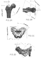
Figure 2A illustrates determination of the distance from the origin to an intersection of femoral plane and femoral axis and shows the angle of the femoral resection plane with respect to the sagittal plane and coronal plane; 2B shows a secondary angle of resection; 2C Shows the vertical tilt of the acetabular cup plane, measured from the sagittal plane, and the method of determining the location of the cup plane; 2D Shows the anteversion of the acetabular cup plane (90-75=Anteversion), measured from the coronal plane. -
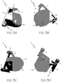
Figure 3A is an exterior bottom-facing view of an exemplary pin locating jig showing two contoured nub ends and a patient-specific contoured body surface; 3B is an exterior bottom view of the same jig showing three contoured nub ends and a patient-specific contoured body surface; 3C is a perspective view of an exemplary pin locating jig with threaded nubs; 3D illustrates the use of cannulated screw caps as spacer elements according to specific embodiments. -
Figure 4A is a sagittal cross-sectional view of a nub of a pin-locating jig with a spacer element comprising a cannulated screw cap engaged to the threaded end of the nub; 4B shows a specific embodiment of a pin-locating jig prior positioned in the acetabulum prior to insertion of surgical pins. -
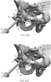
Figure 5A illustrates an exemplary pin-locating jig positioned in the acetabulum prior to insertion of surgical pins. 5B illustrates an exemplary pin-locating jig after insertion of surgical pins prior to clipping of tabs to remove the body. -
Figure 6 illustrates a specific embodiment of a secured pin rail system formed after tabs are clipped from the pin locating jig. -
Figure 7A illustrates an acetabular reamer engaged in an exemplary reamer jig being guided into position in the acetabulum by a pin rail system with spacer elements. 7B illustrates an acetabular reamer engaged in an exemplary reamer jig being guided into position in the acetabulum by a pin rail system with spacer elements comprising cannulated screw caps. -
Figure 8A depicts one embodiment of an impactor jig; 8B shows engagement of an impactor device through the axial bore of the impactor jig. -
Figure 9A shows engagement of an embodiment of an impactor jig to a pin rail system to guide the impactor cup into the acetabulum; 9B shows full insertion of the impactor jig into the impactor cup. -
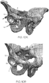
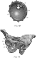
Figure 10A shows an implant cup seated in the acetabulum with an exemplary pin rail system still secured; 10B shows the implant cup seated in the acetabulum after removal of the exemplary pin rail system. -
Figure 11A illustrates a specific embodiment of an implant cup screw jig; 11B shows the screw jig inserted into the implant cup such that the screw jig holes align with the screw holes in the cup. -
Figure 12A depicts a specific embodiment of a patient-specific femoral resection jig; 12B illustrates placement of the jig on the femur and relative positioning of the surgical pin holes and cut guide. -
Figure 13A depicts an exemplary patient-specific femoral version guide positioned on a resected femoral face and having a reaming jig inserted; 13B is another angle of the femoral version guide of A; 13C depicts the exemplary femoral version guide with the insert jig removed exposing a surface of the femoral face. -
Figure 14 illustrates a specific embodiment of a patient-specific femoral version guide having a broaching jig inserted into the opening of the femoral version guide. -
Figure 15A depicts and exemplary embodiment of a femoral resection jig with a removable indicator; 15B illustrates the resection jig and indicator positioned together on the femur; 15C illustrates the resection jig in position after removal of the version indicator. - The figures are not intended to be limiting in any way, and it is contemplated that various embodiments of the invention may be carried out in a variety of other ways, including those not necessarily depicted in the figures. The accompanying figures incorporated in and forming a part of the specification illustrate several embodiments of the present invention, and together with the description serve to explain the principles of the invention, it being understood, however, that this invention is defined and limited only by the appended claims.
- The present disclosure provides a personalized Total Hip Arthroplasty system. The following acronyms are used throughout the disclosure: THA - Total Hip Arthroplasty; CAD - Computer Aided Design; CT - Computed Tomography. The following definitions also apply. Acetabular vertical tilt is the angle from the sagittal plane on the coronal plane on the hip. Acetabular anteversion is the planar angle from the anterior perpendicular of the line of acetabular vertical tilt. Femoral anteversion is the angle from the coronal plane on the axial plane on the femur. A surgical reamer is a device used with a surgical drill to create an appropriately sized cavity in the acetabulum for implantation of an acetabular cup as a part of THA. A surgical impactor is a device used to impact the acetabular cup component into the acetabular cavity following reaming. A broach is a device used to create an appropriately sized cavity in the intramedullary canal of the femur for implantation of the femoral stem prosthetic component into the femur. A "trial" is a surgical device which replicates the implant and is placed in the joint prior to implantation to assist in finalizing an appropriate implant size. A jig is a tool or procedure-guiding device that may removably adhere to a structure and guide the tools and/or the surgeon operating on the structure. A jig may be designed to operationally interact with another jig to ultimately guide tools and/or a surgeon operating on a structure. A jig is not generally a part of a prosthetic, but is intended to be removed from the surgical field after functional use. All terms not expressly defined herein are to be accorded their ordinary meaning in the arthroplastic arts.
- Various illustrative embodiments and aspects of the total hip arthroplasty (THA) system with jigs and jig-device assemblies will be discussed with reference to
Figures 3A-11B . The hip is a ball and socket joint. It is ordinarily very mobile with a large degree of motion. The two main components of the joint are thehead 105 of thefemur 100 and theacetabulum 1 as depicted inFigure 1 . There isarticular cartilage 103 between thehead 105 of thefemur 100 and theacetabular cavity 102. Theacetabular cavity 102 and thesurrounding rim 104 comprise theacetabulum 1. Thefemoral neck 106 connects thefemoral head 105 and a portion of the femur comprising thegreater trochanter 107 and the lesser trochanter 108. The skeletal components are surrounded by musculature and connective tissue. During a THA it is important to do as little damage as possible to the surrounding musculature. - Generally, a THA procedure is fairly standard and includes the following procedural steps:
- 1. Gain access to the hip through an incision
- 2. Remove the capsule and dislocate the femoral head from the acetabular cup
- 3. Cut off the femoral head
- 4. Place prosthetic into femur
- 5. Ream acetabular cup
- 6. Place acetabular prosthetic into acetabular cup
- 7. Relocate the joint
- 8. Close incision
- Each step may include several distinct surgical procedures as well. It is well-known in the art to use temporary/removable jigs to guide placement of THA prosthetics. Known jigs may come in a variety of sizes, each intended to accommodate a range of patient sizes and geometries. Typically pre-operative imaging is employed to aid in determination of prosthesis and jig sizes; although a surgical team may keep several sizes available for rapid interchanging during a procedure where necessary. This rudimentary level of individualization of jigs is outside the scope of what is considered "patient specific" in accordance with the instant disclosure. "Patient-specific"
- In accordance with some embodiments of the invention, a patient's hip is imaged, for example by CT-scanning and a CAD system is employed for pre-operative modeling of relevant jigs, including a patient-specific acetabular reaming and impacting jig system. Although THA generally includes both aspects, one or the other of the procedures may be performed on any given patient as indicated by the patient's condition. For purposes of comprehensiveness, jig modeling/manufacture and implantation is discussed herein for a bilateral total hip replacement procedure.
- Following the THA procedure, the patient's hip is again CT-scanned and the precision of the implantations may be evaluated. The use of the femoral resection jig in THA enhances precision and accuracy in location of a femoral neck resection, and permits refined anteversion of the femoral implantation. Accuracy in controlling the vertical tilt and anteversion of acetabulum implantation, and accuracy in controlling depth of acetabular implantation are enhanced by employing patient-specific manufacturing of jigs according to embodiments of the invention, wherein the jigs are manufactured according to models generated from CAD based on data derived from imaging a patient's unique anatomical features. The examples further illustrate the feasibility of performing a THA procedure with the inventive bone contouring resection, reaming, and impaction devices.
- An acetabular reaming and impacting assembly is generally designed to control the angle of acetabular cup reaming and impacting during a THA procedure, and to provide adjustable control over the depth of reaming. A patient-specific acetabular reaming and impacting assembly according to embodiments of the invention comprises jigs manufactured from the patient-specific model, and jigs integrated with proprietary tool devices. Referring to
Figures 3 ,4 and5 , according to the invention, the assembly comprises apin locating jig 2 comprising abody 4 having a periphery 6 and a least three patient-specificcannulated nubs 8, each nub attached to the periphery 6 by at least onetab 10 and having at least oneend 12 contoured to engage a portion of anouter rim 104 of anacetabulum 1 of the patient at a self-selecting position and through which asurgical pin 14 may be inserted and secured to theouter rim 104 of theacetabulum 1. Thepin locating jig 2 may be manufactured to achieve patient-specificity by the contoured ends 12 of thenubs 8, which match a portion of the patient's acetabulum rim topography, and thebody 4 may further comprise at least onesurface 40 contoured as a negative of an inner surface 5 of the patient'sacetabulum 1. Where included, the additional contoured surface enhances the self-selective positioning of the jig on theacetabulum 1. - With reference to
Figure 6 , upon removal of thebody 4, apin rail system 16 is formed. The pin rail system comprises at least threesurgical pins 14, each secured through anub 8 to theouter rim 104 of theacetabulum 1 forming a base 18. Removal of the body may be effectuated by clipping the at least onetab 10. According to some embodiments eachnub 8 is attached to thebody 4 by 1, 2 or 3clippable tabs 10. Once thepin locating jig 2 is secured, the surgeon clips the tabs and discards thebody 4 leaving thepin rail system 16 secured in place along theouter rim 3 of theacetabulum 1. - According to the invention, the assembly further comprises a
removable reamer jig 20 comprising at least three peripheral pin holes 22, each hole corresponding to apin 14 of thepin rail system 16 permitting engagement of thereamer jig 20 to thepin rail system 16, and anaxial bore 24 through which anacetabular reaming device 26 may be inserted and attached. "Periphery" in the context of the reamer and impactor jigs according to the invention indicates a location at or near an outer edge of a geometric plane formed by the at least three pin holes and corresponding to an acetabular plane. The jig itself need not possess a planar morphology and may have various surface features and device attachment accommodations. According to specific embodiments each of the at least three peripheral pin holes 22 is located at the periphery by aspoke 41 extending from a perimeter of the axial bore. Thespokes 41 may not be contiguous, may be partially contiguous, or may be substantially contiguous. In some embodiments of thereamer jig 20, the peripheral pin holes 22 are closed or substantially closed, and thejig 20 engages and disengages from thepin rail system 16 by sliding on and off thepins 14. In other embodiments of thereamer jig 20, the peripheral pin holes 22 are open and the opening is angled toward the periphery such that engagement and disengagement of thejig 20 to thepins 14 of thepin rail system 16 is effectuated by aligning thejig 20 in thepin rail system 16 and turning it clockwise or counter-clockwise, alternately with respect to engaging and disengaging. - The assembly may also comprise a set of
spacing elements 28, generally one for eachnub 8. The number of size of spacing elements may vary with the CAD generated for the patient. A spacing element may provide a discrete spacing accommodation, or a continuous spacing accommodation. The spacing element determines the depth to which thereaming device 26 will insert into theacetabular cup 102. In certain embodiments, a discrete spacing element may slide over asurgical pin 14 and sit at the base of thepin rail system 16. In other specific embodiments as depicted inFigures 3C and 3D and detailed inFigure 4 , anub 8 may comprise a threadedportion 9 comprising a length and a pitch of threading, and a spacing element may be a cannulatedscrew cap 11 which screws onto the threadedportion 9 by an adjustable amount, providing a highly precise continuous spacing accommodation across the threadedportion 9. - With reference to
Figures 8 ,9 and10 , the assembly further comprises aremovable impactor jig 30 comprising at least three peripheral pin holes 32, each hole being substantially closed and corresponding to a pin of thepin rail system 16 such that theimpactor jig 30 slidingly engages with and disengages from thepin rail system 16, and acup portion 34 sized to fit into aprosthetic implant cup 36, and anaxial bore 39 through which anacetabular impacting device 42 may be inserted to guide and impact theimplant 36 into position in theacetabulum 1. The cup portion comprises an outer surface, the outer surface intended to operationally contact an inner surface of an implant cup. In specific embodiment the outer surface 33 of thecup portion 34 comprises a set ofprotrusions 35 located to fit and engage a corresponding set of screw holes 37 in theimplant cup 36. According to specific embodiments, the desired location of the screw holes 37 is pre-operatively determined and patient-specifically modeled asprotrusions 35 on theimpactor jig 30. In some embodiments, the impactingdevice 35 comprises ahandle 43 which slides and spins freely within the axial bore 39 of the impactingjig 30 such that when thejig cup portion 34 is inserted into theacetabular implant cup 36, thehandle 43 may be turned, turning theimplant 36 until the set of screw holes 37 in theimplant cup 36 engages with the set ofprotrusions 35 on theimpactor jig 30, which is held stationary by engagement with thepin rail system 16. The engagement of theprotrusions 35 by the screw holes 37 restricts rotation of theimplant cup 36 to a pre-operatively determined patient-specific angle. - In certain embodiments, as specifically illustrated in
Figure 11 , aplastic implant liner 46 is provided with a set ofholes 45 which are designed to guide patient-specific placement ofsurgical screws 49 to secure theimplant cup 36 andliner 46 into theacetabulum 1. The liner screw holes 45 correspond to the implant cup screw holes 37 and may be angled to guide insertion and drilling of the surgical screws 49. Theimplant liner 46 may also include one ormore corrugations 39 forming a corrugated pattern along an outside peripheral edge of theliner 46 which matches and engages a corresponding corrugated pattern along an inside peripheral edge of theimplant liner 46 thereby securing it into proper position within theimplant cup 36. - Aspects of the acetabular reaming and impacting assembly, including features of the pin locating jig, spacer elements, impactor jig, impactor jig cup portion, and screw locator jig are designed to be patient-specific matches to unique anatomical features of the particular patient by manufacturing according to a model generated pre-operatively by computer-aided design, from data derived by imaging of a pelvic acetabular region of the particular patient.
- Also described herein is a patient-specific
femoral resection jig 50. A specific examples is depicted inFigure 12 , with an alternative example depicted inFigure 15 . The femoral resection jig is manufactured from a patient-specific model generated pre-operatively by computer-aided design from data derived from imaging of femoral region of the patient. Theresection jig 50 comprises: amonolithic body 51 having at least proximal, distal, medial and lateral surfaces, the distal surface 52 providing aresection reference 54 for guiding a cutting instrument to resect afemoral head 105, the medial surface 56 comprising a patient-specific surface 58 contoured as a negative to a surface of the patient'sfemoral neck 106 such that the jig self-selects to engage a position on the surface of thefemoral neck 106, and a medial-distal corner 60 positioned upon engagement to provide a visual indicator of version. - According to specific examples, the
resection reference 54 may be a cut-guiding surface against which a surgical blade is placed and guided. In other specific examples theresection reference 54 is a slot in themonolithic body 51 in which a surgical blade may be placed and guided along thefemoral neck 106. Theresection reference 54 guides the blade both with respect to placement and angle. Themonolithic body 51 may be any shape, so long as it provides the required faces. By "monolithic" it is understood that the body exists as a single operational unit, although the body may be manufactured in parts. In specific examples, the monolithic body is substantially in the form of a rectangular or trapezoidal prism. Afemoral resection jig 50 will typically haveholes 64 through which surgical pins may be inserted and drilled to secure thejig 50 to thefemur 100. In a specific example, the femoral resection jig has two surgical pin holes. In an alternative design, afemoral resection jig 50 comprises a removableversion indicating guide 66, as depicted inFigure 15 . Theversion indicating guide 66 is patient-specific and located at a medial-distal corner 68 of theversion indicating guide 66. - Referring now to
Figure 13 andFigure 14 , an exemplary patient-specific femoral version assembly 70 is depicted. The femoral version assembly comprises aversion guide 72 contoured to fit a portion of arim 71 of a resectedface 74 of afemur 100 and to substantially cover the resectedface 74; the guide comprising an opening 75 to the resected face into which one or more standard insert jigs may be placed. Insert jigs may include a reamingjig 77, and a broaching/implant placement jig 78. The insert jigs may be seated and removed under intra-operational conditions. A specific jig insert comprises a reamingjig insert 77 comprising an opening positioned to direct a reamer through the resected face of the femur, guiding the reamer down theintramedullary canal 80. Another specific jig insert comprises a broaching jig insert 78 comprising an opening positioned to direct a broach into the resected face of the femur with the correct anteversion. A suitable broaching jig may also be an implant placement jig, or the implant placement jig may be a distinct insert. - A patient-specific femoral version assembly comprises a version guide manufactured from a patient-specific model generated pre-operatively by computer-aided design from data derived from imaging a contemplated resected femoral face and rim of the contemplated resected femoral face of the patient. Femoral version guides all have the same shape and size cut-out, with a set position for the insert jigs. A set of reamer insert jigs, one for each size of a reamer is provided, allowing for serial reaming. The reamer insert jigs are all shaped to fit the cut-out; however the opening may be serially adapted. Standard femoral broach insert jigs are also sized to fit the version guide cut-out. Broaching insert jigs comprise an opening shaped exactly to a cross section of a broach. A set of broach insert jigs, one for each size broach, is provided, allowing for serial broaching. Standard femoral implant insert jigs all have the same shape and size perimeter designed to fit the version guide cut-out. The implant insert jig comprises an opening shaped exactly to the cross section of the femoral stem implant. A set of implant jig inserts, one for each size femoral stem implant, is provided, allowing for the implantation of the appropriately sized implant. In particular examples a broach insert jig may function as an implant insert jig.
- Additional embodiments of the invention are directed to methods. According to the invention, a method for fabricating a patient-specific acetabular reaming and impacting assembly comprises generating a computer-aided design- based model of a pelvic acetabular region of a patient. The model comprises a referencing coordinate system generated from 3-D imaging of the patient's relevant anatomy, in particular the pelvic acetabular regions with respect to THA. Features of a jig in accordance with the invention is designed to precisely fit the surface topography of the patient's bone and therefore, when guided generally into place by the surgeon, self-selectively engage with the matching portion of the pelvic acetabular region. Spacer dimension and number may also be determined in accordance with the model to reflect and accommodate desirable depth and angle of insertion of the prosthetics. Jig features may be designed to provide more precise placement and angulation of surgical pins, tools and screws, and to provide precise guidance as to a desired resection location and plane.
- Methods for fabricating a patient-specific femoral resection jig, for example, comprise generating a computer-aided design model of a head and neck region of a femur of a patient, superimposing a reference coordinate system on the anatomical structures based on the patient's specific anatomy, and constructing a model of a patient-specific femoral resection jig in accordance with the reference. It is understood that the surgeon ultimately selects securing/incision/resection points, aided by the anatomical models, and the surgeon's selection is incorporated into a jig model. In a specific example of patient specificity, a femoral version guide may be fabricated to precisely fit the resected face and rim of a patient's femur in order to provide the surgeon with an efficient guide to resection and broaching, as determined pre-operatively by the surgeon upon inspection of the computer aided design.
- The methods, devices and jigs integrate into a total hip arthroplasty system providing patient-specific control of hip geometry such that a femoral stem implant and an acetabular cup implant are positioned relative to one another with a hip geometry ideal for a specific patient. The total hip arthroplasty system includes design and fabrication of various examples of a patient-specific acetabular reaming and impacting assembly, a removable impactor jig, a patient-specific femoral resection jig, and a patient-specific femoral version assembly. The total hip arthroplasty system provides patient-specific accommodation of, for example, anteversion, vertical tilt, acetabular reaming depth, femoral reaming, location and angle of femoral broaching, and location and angle of femoral stem implantation.
- It is understood however, that depending on the condition and indications of a particular patient, aspects of the total hip arthroplasty system may be utilized independently of one another. For example, a patient-specific femoral resection jig and femoral version assembly may be utilized in a hemiarthroplasty procedure.
- The following examples are intended to illustrate specific examples, aspects and features and should not be construed to limit the full scope of the claims as set forth herein.
- This Example illustrates a particular cadaveric protocol for pre-operative design aspects of a patient-specific total hip arthroplasty system.
- Pre-operative CT-Scanning may be undertaken to provide information about a patient's anatomical geometry and bone structure, including for example bone surface topography. Reference points may be created or identified. For example, three surgical pins may be pre-operative inserted. The patient is CT-imaged in a normal supine position and in several alternative positions. Anywhere from 3 to 10 scans is acceptable, although more scans may be taken as time and resource commitment permits. At least one CT-image is taken with enough traction on the leg to pull the femoral head from the acetabular cup and the traction is recorded. The CT-scans are processed to generate anatomical planes and an anatomical plane coordinate system. In very specific exemplary examples, the CT-scans are processed using Amira™ software into .STL files for SolidWorks™ (SolidWorks is a proprietary software product for 3-D modeling in a wide variety of industries and is licensed from Dassault Systèmes SolidWorks Corp. of Waltham, Mass.). The .STL files are imported into SolidWorks™ to generate anatomical planes (sagittal, coronal, lateral, e.g., in accordance with ordinary meaning) and the distance of each plane to each surgical pin is measured. Software may be employed to create a template of the hip from this data. In a specific example, DePuy proprietary software (DePuy Companies is a part of the Johnson & Johnson Companies and the licensor of Pinnacle® hip system and Summit® cementless hip system tools and corresponding software) may be utilized in conjunction with imaging data to determine appropriate implant size and approximate location for right and/or left hip replacements. Specific prosthetics/implants are selected and modeled in SolidWorks™ to create a model assembly. In a specific example, a Summit™ femoral implant and a Pinnacle® acetabular cup implant are modeled and placed in approximate implantation location. Positioning of the implants is confirmed or adjusted by a surgeon checking against the template generated from the DePuy hip templating software. A suitable location for femoral resection and acetabular cup placement is determined in SolidWorks™ for the affected hip joint. Screen shots are taken of the templating assembly showing the final location of the implants. It is understood that a surgeon determines final locations of resection and implant positions with reliance on the modeling for precise guidance.
- The position of a femoral resection plane and acetabular cup location with respect to the anatomical plane coordinate system is recorded. The angle of the femoral resection plane with respect to the sagittal plane and coronal plane is recorded and the distance from the origin to an intersection of femoral plane and femoral axis is determined as shown in
Figure 2A . A secondary angle of resection is illustrated inFigure 2B . - The angle of anteversion and vertical tilt of the acetabular cup plane are shown in
Figures 2C and 2D. Figure 2C illustrates the distance from origin to intersection of acetabular cup plane and longitudinal axis. The distance from the center of the cup on acetabular plane to the opposing, internal/proximal face of hip bone is shown inFigure 2D . - The following provides a basic algorithm for the creation of the relevant anatomical planes.
-
- a. Create the Sagittal plane using a mid-point on the pubis, the most inferior point on the sacrum, and a midpoint on a lumbar spine.
- b. Create the Coronal plane by selecting the anterior most point on the iliac spine, the anterior most point on the pubis, and setting the plane perpendicular to the Sagittal plane.
- c. Create the Axial plane by selecting the inferior most point on the ischium and setting the plane perpendicular to the Sagittal plane and Coronal Plane. The intersection of these three planes is now to be considered the origin.
- d. Create the Acetabular Cup Plane
- 1. Set the anteversion by drawing a line on the Coronal plane superiorly from the origin with the angle measured from the Sagittal plane.
- 2. Set the vertical tilt by drawing a line on the Axial plane posteriorly from the origin with the angle measured from the Sagittal plane.
- 3. A plane is created from the two lines defined in the two previous steps. This plane specifies the angle of the cup.
-
- A. Generate femoral axis
- a. Create a plane 15mm±1mm inferior to the lesser trochanter as close to perpendicular with the femur as possible.
- b. Find the center of the intramedullary canal on the new created plane by finding the intersection of two diameters (one of which is coincident on the Linea Aspera).
- c. Create a second plane parallel to the one created in 2(A)(a) 60mm±1mm superior to the epicondyles.
- d. Find the center of the intramedullary canal on this new created plane by drawing a sagittal line through the cross-section and finding the midpoint.
- e. The femoral axis is created by selecting the two created points within the intramedullary canal.
- f. Generate the axial plane by setting the plane perpendicular to the femoral axis and coincident to the superior-most point on the greater trochanter.
- B. Generate the Coronal Plane
- a. On the Axial plane, draw the transepicondylar axis by connecting the lateral and medial epicondylar peaks.
- b. The Coronal plane is generated by setting the plane perpendicular to the Axial plane, parallel with the line created in step 2(B)(a), and coincident with the femoral axis created in step 2(A)(e).
- C. Generate the Sagittal plane
- a. set the plane perpendicular to the Coronal plane and coincident with the femoral axis.
- The above process allows a set of DICOM images to be changed into a SolidWorks™ surface, from which an anatomical coordinate system can be defined. This process can be validated and optimized by changing the values for threshold, number of faces, max dist, and min dist.
- This example illustrates an aspect of data transfer of the CT-scan DICOM images into 3-D models in SolidWorks™ using Amira™ (Amira is a proprietary software platform for 3-D and 4-D data visualization, processing, and analysis in life science applications and is licensed from FEI Visualization Sciences Group, Bordeaux, France).
- A CT scan takes a large number of 2-D x-rays and uses geometric processing to create a 3-D image. Each x-ray or slice creates a DICOM image. The combination of the 2-D x-ray resolution and the slice thickness creates a voxel (volumetric pixel). According to a very specific example, the CT data used has a voxel size of .78125mm x 1.2mm x .78125mm. Amira™ is a 3-D data visualization, analysis, and modeling program. In particular examples it may be employed to separate the desired anatomy from the rest of the CT scan data and convert the data into a format that can be imported into SolidWorks™ as a 3-D model. STL files are created. The STL files approximate the geometry of the data by simplifying it into a specified number of triangles. STL files are easily imported into SolidWorks™.
- This example illustrates methods and particular assemblies, jigs and systems through an exemplary Total Hip Arthroplasty procedure on a cadaver.
- STL mesh files of CT scans are processed into surfaces in SolidWorks™. The femoral resection guides in SolidWorks™ are updated to reflect patient-specific bone geometry and a surgeon approves the line of resection. Anterior and posterior jig systems may be created for both left and right femurs. The SolidWorks™ acetabular guide system is also updated to reflect patient-specific bone geometry and a surgeon approves the angle of anteversion, vertical tilt, and depth. One rim locating jig model and one cup locating jig model may be created for either or both of the left and right hip.
- The THA procedure is performed on the right and left hip of the cadaver using the patient-specific reaming, resecting, and impaction jigs. An anterior approach is used on one side, while a posterior approach is used for the other. Upon completion of the procedure, the cadaver is transported to radiology for CT-imaging. This post-op imaging includes supine position scans. The scans are analyzed.
- Plane Generation. Anatomical planes are generated by defining the distances from the surgical pins to each plane defined in Example 2.
- Acetabular Cup Location and Angulation Determination. The angle of the implanted acetabular cup is determined with respect to the anatomical planes for both the left and right hip. The angle of the cup placement is compared to the pre-operative intended angulation for both the left and right hip. The coordinates of the center of the cup on the plane of cup angulation is calculated with respect to the anatomical planes for both the left and right hip. Cup placement is compared to the pre-operative intended location for both the left and right hip. The distance from the center of the acetabular implant to the proximal face of the hip bone for both the left and right hip and compared to the pre-operative intended distance for both the left and right hip.
- Femoral Plane Location and Angulation Determination. The angle of resection on the femoral neck with respect to the anatomical planes are determined for both the left and right femur, and compared to the pre-operative intended angulation for both the left and right femur. The location of the intersection of the femoral resection plane and the femoral axis is determined for both the left and right femur, and compared with the pre-operative intended location for both the left and right femur.
- Acetabular reaming and impacting assembly
- 1. Pin location jig fits onto Acetabular cup securely
- 2. Pins can be placed using pin location jig
- 3. Pin location jig can be clipped leaving behind only the spacer pieces on bases
- 4. Reamer jig connects DePuy Acetabular reamer to pins and allows for Acetabular reaming
- 5. Spacers function to restrict acetabular reaming to a specified depth
- 6. Impactor jig connects DePuy Acetabular cup impactor to pins and allows for Acetabular implant impacting
- 7. Entire Acetabular reaming and impacting assembly can be removed from surgical field
- 8. Acetabular cup is anteverted within +/- 10° of desired angle (range of safe zone in the art)
- 9. Acetabular cup has a vertical tilt within +/- 10° of desired angle (range of safe zone in the art)
- Femoral resection and version assembly
- 1. Femoral resection jig fits onto the neck of the femur securely
- 2. Femoral resection jig can be securely fixed to femoral neck
- 3. Version indicator can be made and seen during broaching and stem impaction
- 4. Neck cut can be made along the femoral cutting reference
- 5. Neck cut is in target location
- 6. Midplane of stem aligns with the target location
- Clinical Outcome
- 1. Leg is adjusted to appropriate length
- 2. Hip is adjusted to appropriate offset
- This Example illustrates a THA procedure illustrating specific examples of methods, an acetabular reaming and impacting assembly and a femoral resection and version assembly.
- An acetabular reaming and impacting assembly includes the major components of a pin location jig, a pin rail system, an acetabular reaming jig, an acetabular impacting jig, and optionally a screw locating jig. The jigs are patient-specifically designed to control the angle of acetabular cup reaming and impacting during a THA procedure. The assembly, and in particular the pin rail system and spacers, also controls the depth of reaming. The hip joint is exposed and the femur is dislocated from the Acetabular cup as in normal THA procedure. The rim of the cup is cleaned such that the bone contouring pin locator can be placed onto the cup. The pin locating jig is placed on the Acetabular cup. The cup should self-select a position...that is, it assumes a distinct position in which it sits and feels secure. Surgical pins are drilled into position using the pin locator. The tabs located at each nub are clipped. The nubs are left to set a base plane for the spacers and the body of the pin locator is removed. Spacers are stacked on each pin to a desired height. In alternative examples a spacer element comprising a cannulated screw cap is screwed onto a threaded portion of a nub a predetermined height. The desired height is determined to control the depth of the reamer. The reamer guide is attached to, for example, a DePuy hip system Reamer. The reamer is moved into the surgical field and the reamer jig is rotated until it engages with the 3 pins of the pin rail system. Reaming is performed to the depth allowed by the spacers. Spacer height may be adjusted intraoperatively until the desired reaming depth has been achieved. Afterward, the reamer and reamer jig are removed from the surgical field. The impactor jig is then attached to the DePuy hip system Impactor. The impactor is moved into surgical field and impactor jig may be engaged to the pin rails by sliding from the top through the pin holes in the jig, or in alternative examples it may be rotated until it engages with the rails of the pin rail system. The acetabular cup is impacted into position and thereafter the impactor and impactor jig are removed from the surgical field. The surgical pins are then removed from the pelvis. The femur is re-approximated to the cup and wound is closed as in a normal THA procedure.
- The femoral jig is designed to control and guide the location and angle of the femoral neck cut during a THA procedure. In some examples the jig also allows for the creation of a visual indicator of version to assist in alignment during broaching and stem impaction. In some examples the resection jig and version jig are an inseparable single body. In other specific examples the resection jig and version jig are two distinct pieces. The femoral resection jig is patient-specifically designed to fit in position on the femoral neck in a self-selecting location. The resection jig may include pin holes so that it may be attached to the neck of the femur using surgical pins. The resection jig may have a reference cutting face which permits location of the precise femoral neck cut and guiding of the femoral resection tool. In some examples the resection jig may comprise a slot which operates to guide the resection tool. The jig may also have a corner by which a mark can be made on the bone to indicate proper version.
- The hip joint is exposed and the femur is dislocated from the acetabular cup as in an ordinary THA procedure. In a very specific examples, the femoral resection jig is placed onto the neck of the femur and should self-locate into a distinct position in which the jig will feel secure. The jig may be specifically designed for placement on either the anterior or posterior side of the neck and the side chosen will depend on the type of approach being performed. Surgical pins are drilled into position to fix the resection jig in place. A linear mark may be made on the femur adjacent to the most medial and distal corner of the guide. This mark indicates proper version for the femoral implant. A femoral neck cut is made using a surgical cutting tool such as a surgical saw, thus resecting the femoral head. Care is taken to keep the blade flat against the resection jig reference cutting face in order to avoid cutting at an oblique angle. The intramedullary canal is broached and the femoral stem implant is impacted in accordance with ordinary THA procedures; however using the bone mark as a visual indicator of proper version. In other specific examples a femoral version jig may be positioned across the face of the femur to be broached. The jig is patient-specifically designed to self-select a position on the rim of the resected femur and to provide a guide for insertion of broaching devices. The femoral version jig includes a cut-out for insertion of broaching jigs which guide the broaching procedure. As before, the femoral stem implant is impacted in accordance with ordinary THA procedures. The femur is then reapproximated to the cup and the wound is closed.
Claims (14)
- A patient-specific acetabular reaming and impacting assembly comprising:a pin locating jig (2) comprising a body (4) having a periphery (6) and a least three patient-specific cannulated nubs (8), each nub (8) attached to the periphery (6) by at least one tab (10) and having at least one surface (40) contoured to engage a portion of an outer rim (104) of an acetabulum (1) of the patient at a self-selecting position and through which a surgical pin (14) may be inserted and secured to the outer rim (104) of the acetabulum (1), where upon removal of the body a pin rail system (16) is formed comprising at least three surgical pins (14), each secured through the respective nub (8) forming a base;a removable reamer jig (20) comprising at least three peripheral pin holes (22), each hole (22) corresponding to a pin (14) of the pin rail system (16) permitting engagement of the reamer jig (20) to the pin rail system (16), and an axial bore (24) through which an acetabular reaming device (26) may be inserted and attached;at least one set of spacing elements;a removable impactor jig (30) comprising at least three peripheral pin holes (32), each hole (32) corresponding to a pin (14) of the pin rail system (16) permitting sliding engagement of the impactor jig (30) to the pin rail system (16), and a cup portion (34) sized to fit into an implant cup (36), and an axial bore (39) through which, in use, an acetabular impacting device (42) may be inserted to guide and impact the implant into position in the acetabulum (1).
- The acetabular reaming and impacting assembly according to claim 1, wherein removal of the locating jig body (4) is achieved by clipping the tabs (10).
- The acetabular reaming and impacting assembly according to claim 1, wherein the body (4) of the locating jig (2) comprises at least one patient specific surface (40) contoured as a negative of an inner surface (5) of the acetabulum (1) to enhance self-selection positioning of the jig on the acetabulum (1).
- The acetabular reaming and impacting assembly according to claim 1, wherein the spacing elements are spacers for placement at the base of each pin (14) of the pin rail system (16) to provide patient-specific control of the depth of the reamer device (26).
- The acetabular reaming and impacting assembly according to claim 1, wherein:(i) the nubs (8) comprise a threaded portion (9) and each spacer element comprises a cannulated screw cap (11) which screws to a nub (8) to an adjustable height to provide patient-specific control of the depth of the reamer device (26); or(ii) the nubs (8) of the locating jig (2) are each attached to the periphery (6) of the jig (2) by a single tab (10).
- The acetabular reaming and impacting assembly according to claim 1, wherein the at least three peripheral pin holes (32) of the reamer jig (20) are open and oriented such that the reamer jig (20) may be engaged or disengaged from the pin rail system (16) by turning the reaming device (26) clockwise or counterclockwise.
- The acetabular reaming and impacting assembly according to claim 1, wherein the at least three peripheral pin holes (32) of the impactor jig (30) are:(i) open and oriented such that the impactor jig (30) may be engaged or disengaged from the pin rail system (16) by turning the impacting device (42) clockwise or counterclockwise; or(ii) closed such that the impactor jig (30) may be engaged or disengaged from the rail system by sliding on and off the pin rail system (16).
- The acetabular reaming and impacting assembly according to claim 1, wherein an outer surface (33) of the cup portion (34) of the impactor jig (30) comprises a set of protrusions (35) located to fit and engage a corresponding set of patient-specific screw holes (37) in the implant cup (36), preferably wherein the impacting device (42) comprises a handle (43) which slides and spins freely within the axial bore (39) of the impacting jig (30) such that when the jig cup portion (34) is inserted into the acetabular implant cup (36), the implant cup (36) may be turned until the set of screw holes (37) engages with the set of protrusions (35), restricting rotation of the implant cup (36) to a patient-specific angle.
- The acetabular reaming and impacting assembly according to claim 1, wherein each pin hole (22) at the periphery of the reaming jig (77) and/or each pin hole (32) at the periphery of the impacting jig (30) are located at the periphery by a spoke (41).
- The acetabular reaming and impacting assembly according to claim 1, wherein the implant cup (36) comprises a set of screw holes (37) and the assembly further comprises an implant liner (46) comprising patient specific implant screw holes (45) specifically positioned to guide insertion and drilling of one or more surgical screws (49) to secure the implant cup (36) and liner (46) into the acetabulum (1); wherein the liner (46) screw holes (45) correspond to and engage the set of screw holes (37) in the implant cup (36).
- A method for fabricating the patient-specific acetabular reaming and impacting assembly of claim 1, the method comprising: generating a computer-aided design model of a pelvic acetabular region of a patient, the model comprising a referencing coordinate system based on the patient's anatomy, and constructing a pin locating jig (2) contoured to self-selectively engage with a portion of the pelvic acetabular region, and selecting spacer elements in accordance with the model.
- The method according to claim 11, wherein the computer-aided design model is derived from 3-D images of the pelvic acetabular region.
- The method according to claim 11, further comprising locating the set of protrusions (35) on the outer surface (33) of the cup portion (34) of the impacting jig (30) according to the model.
- A total hip arthroplasty system providing patient-specific control of hip geometry such that a femoral stem implant and an acetabular cup implant are positioned relative to one another with a hip geometry ideal for the specific patient, the total hip arthroplasty system comprising:(a) the patient-specific acetabular reaming and impacting assembly of claim 1;(b) a patient-specific femoral resection jig (50) comprising:
a monolithic body (51) having at least proximal, distal, medial and lateral surfaces, the distal surface (52) providing a resection reference (54) for guiding a cutting instrument to resect a femoral head (105), the medial surface (56) comprising a patient-specific surface (58) contoured as a negative to a surface of the patient's femoral neck (106) such that the jig self-selects to engage a position on the surface of the femoral neck, and a medial-distal corner (60) positioned upon engagement to provide a visual indicator of version; and(c) a patient-specific femoral version assembly (70) comprising:
a version guide (72) contoured to fit a portion of a rim (71) of a resected face (74) of a femur (100) and to substantially cover the resected face (74), the guide (72) comprising an opening (75) to the resected face (74) into which a set of jig inserts including a standard reaming jig (77), a broaching jig (78) and an implant placement jig (78) may be seated and removed under operational conditions.
Applications Claiming Priority (2)
| Application Number | Priority Date | Filing Date | Title |
|---|---|---|---|
| US201361778749P | 2013-03-13 | 2013-03-13 | |
| PCT/US2014/025568 WO2014159984A1 (en) | 2013-03-13 | 2014-03-13 | Patient-specific assemblies, jigs, and methods for a personalized total hip arthroplasty system |
Publications (3)
| Publication Number | Publication Date |
|---|---|
| EP2967660A1 EP2967660A1 (en) | 2016-01-20 |
| EP2967660A4 EP2967660A4 (en) | 2016-11-09 |
| EP2967660B1 true EP2967660B1 (en) | 2018-10-03 |
Family
ID=51530966
Family Applications (1)
| Application Number | Title | Priority Date | Filing Date |
|---|---|---|---|
| EP14775248.9A Active EP2967660B1 (en) | 2013-03-13 | 2014-03-13 | Patient-specific assemblies, jigs, and methods for a personalized total hip arthroplasty system |
Country Status (4)
| Country | Link |
|---|---|
| US (1) | US9526514B2 (en) |
| EP (1) | EP2967660B1 (en) |
| AU (1) | AU2014244248B2 (en) |
| WO (1) | WO2014159984A1 (en) |
Families Citing this family (41)
| Publication number | Priority date | Publication date | Assignee | Title |
|---|---|---|---|---|
| FR2932674B1 (en) | 2008-06-20 | 2011-11-18 | Tornier Sa | METHOD FOR MODELING A GLENOIDAL SURFACE OF AN OMOPLATE, DEVICE FOR IMPLANTING A GLENOIDAL COMPONENT OF A SHOULDER PROSTHESIS, AND METHOD FOR MANUFACTURING SUCH COMPOUND |
| EP2451365B1 (en) * | 2009-07-10 | 2015-07-01 | Kirk Promotion LTD. | Hip joint instrument |
| KR102072870B1 (en) | 2011-09-29 | 2020-02-03 | 알쓰로메다, 인코포레이티드 | system and method for precise prosthesis positioning in hip arthroplasty |
| US9649201B2 (en) * | 2011-12-08 | 2017-05-16 | New York University | Anatomic socket alignment guide and methods of making and using same |
| US12121272B2 (en) | 2012-04-18 | 2024-10-22 | Materialise N.V. | Two-part surgical guide |
| CA2887130C (en) | 2012-07-24 | 2020-03-24 | Orthosoft Inc. | Patient specific instrumentation with mems in surgery |
| EP2973220A4 (en) | 2013-03-15 | 2016-10-19 | Arthromeda Inc | Systems and methods for providing alignment in total knee arthroplasty |
| US9492184B2 (en) * | 2013-08-05 | 2016-11-15 | William B. Kurtz | Hip replacement systems and methods |
| US9474614B2 (en) * | 2013-08-08 | 2016-10-25 | Scott Kelley | Acetabular components with radiological markers for a hip replacement implant |
| FR3010628B1 (en) | 2013-09-18 | 2015-10-16 | Medicrea International | METHOD FOR REALIZING THE IDEAL CURVATURE OF A ROD OF A VERTEBRAL OSTEOSYNTHESIS EQUIPMENT FOR STRENGTHENING THE VERTEBRAL COLUMN OF A PATIENT |
| FR3012030B1 (en) | 2013-10-18 | 2015-12-25 | Medicrea International | METHOD FOR REALIZING THE IDEAL CURVATURE OF A ROD OF A VERTEBRAL OSTEOSYNTHESIS EQUIPMENT FOR STRENGTHENING THE VERTEBRAL COLUMN OF A PATIENT |
| EP3068317B1 (en) | 2013-11-13 | 2018-08-22 | Tornier | Shoulder patient specific instrument |
| AU2016349705B2 (en) | 2015-11-04 | 2021-07-29 | Medicrea International | Methods and Apparatus for spinal reconstructive surgery and measuring spinal length and intervertebral spacing, tension and rotation |
| WO2017105815A1 (en) * | 2015-12-16 | 2017-06-22 | Tornier, Inc. | Patient specific instruments and methods for joint prosthesis |
| EP3685804A1 (en) | 2016-03-25 | 2020-07-29 | Tornier | Joint prosthesis spacer |
| CN105816232A (en) * | 2016-05-17 | 2016-08-03 | 南方医科大学 | Design and molding method of anatomical bone plate for individualized bone model |
| WO2018109556A1 (en) | 2016-12-12 | 2018-06-21 | Medicrea International | Systems and methods for patient-specific spinal implants |
| GB201705919D0 (en) * | 2017-04-12 | 2017-05-24 | Depuy Ireland Ultd Co | Trial Neck |
| JP7165668B2 (en) | 2017-04-21 | 2022-11-04 | メディクレア インターナショナル | System for developing one or more patient-specific spinal implants |
| US11185377B2 (en) | 2017-06-09 | 2021-11-30 | Mako Surgical Corp. | Systems and tools for positioning workpieces with surgical robots |
| US11234721B2 (en) | 2017-07-11 | 2022-02-01 | Howmedica Osteonics Corp. | Guides and instruments for improving accuracy of glenoid implant placement |
| EP3651662B1 (en) | 2017-07-11 | 2025-07-02 | Howmedica Osteonics Corp. | Patient specific humeral cutting guides |
| US10729558B2 (en) | 2017-08-18 | 2020-08-04 | Zimmer, Inc. | Methods and systems for patient-specific acetabular implants |
| US10918422B2 (en) | 2017-12-01 | 2021-02-16 | Medicrea International | Method and apparatus for inhibiting proximal junctional failure |
| EP3731783A1 (en) | 2017-12-29 | 2020-11-04 | Tornier, Inc. | Patient specific humeral implant components |
| CN108742770A (en) * | 2018-06-20 | 2018-11-06 | 重庆大学 | For the rasion guide plate of total hip arthroplasty and its manufacture, application method |
| CN109106475B (en) * | 2018-08-17 | 2024-08-16 | 北京威高亚华人工关节开发有限公司 | Acetabular cup guide plate and manufacturing method thereof |
| US11103367B2 (en) | 2019-02-15 | 2021-08-31 | Encore Medical, L.P. | Acetabular liner |
| US11925417B2 (en) | 2019-04-02 | 2024-03-12 | Medicrea International | Systems, methods, and devices for developing patient-specific spinal implants, treatments, operations, and/or procedures |
| US12564447B2 (en) | 2019-04-02 | 2026-03-03 | Medicrea International | Systems, methods, and devices for developing patient-specific spinal implants, treatments, operations, and/or procedures |
| US11877801B2 (en) | 2019-04-02 | 2024-01-23 | Medicrea International | Systems, methods, and devices for developing patient-specific spinal implants, treatments, operations, and/or procedures |
| US11944385B2 (en) | 2019-04-02 | 2024-04-02 | Medicrea International | Systems and methods for medical image analysis |
| CN110974490B (en) * | 2019-11-28 | 2021-09-14 | 佛山市逸合生物科技有限公司 | Manufacturing method of personalized acetabular cup with bone defect repair function |
| US11769251B2 (en) | 2019-12-26 | 2023-09-26 | Medicrea International | Systems and methods for medical image analysis |
| US12004967B2 (en) * | 2020-06-02 | 2024-06-11 | Howmedica Osteonics Corp. | Systems and methods for planning placement of an acetabular implant for a patient based on pelvic tilt |
| CN113693726B (en) * | 2020-12-11 | 2025-01-10 | 捷多(常州)医疗科技有限公司 | Robotic-assisted joint replacement surgery system fixed to bones and method of use |
| CA3216633A1 (en) | 2021-04-27 | 2022-11-03 | Nick Metcalfe | Orthopaedic implant systems including transfer features and methods for plan transfer |
| US12318144B2 (en) | 2021-06-23 | 2025-06-03 | Medicrea International SA | Systems and methods for planning a patient-specific spinal correction |
| US12558110B2 (en) * | 2021-12-22 | 2026-02-24 | Howmedica Osteonics Corp. | Screw-through acetabular cup system and methods of using the same |
| CN117243664A (en) * | 2023-11-05 | 2023-12-19 | 中国人民解放军陆军军医大学第一附属医院 | A hip-preserving osteotomy guide fixator and its assembly method based on 3DP technology |
| DE202024102810U1 (en) * | 2024-05-29 | 2024-07-18 | Universität Heidelberg, Körperschaft des öffentlichen Rechts | Trial prosthesis, impactor and system for positioning and implanting a prosthesis and use of the system for positioning and implanting a prosthesis |
Family Cites Families (10)
| Publication number | Priority date | Publication date | Assignee | Title |
|---|---|---|---|---|
| US7534263B2 (en) * | 2001-05-25 | 2009-05-19 | Conformis, Inc. | Surgical tools facilitating increased accuracy, speed and simplicity in performing joint arthroplasty |
| AUPR865701A0 (en) * | 2001-11-02 | 2001-11-29 | Egan, Michael | Surgical apparatus and surgical methods |
| US9339278B2 (en) * | 2006-02-27 | 2016-05-17 | Biomet Manufacturing, Llc | Patient-specific acetabular guides and associated instruments |
| US8603180B2 (en) * | 2006-02-27 | 2013-12-10 | Biomet Manufacturing, Llc | Patient-specific acetabular alignment guides |
| US8992538B2 (en) | 2008-09-30 | 2015-03-31 | DePuy Synthes Products, Inc. | Customized patient-specific acetabular orthopaedic surgical instrument and method of use and fabrication |
| WO2010124164A1 (en) * | 2009-04-23 | 2010-10-28 | Ure Keith J | A device and method for achieving accurate positioning of acetabular cup during total hip replacement |
| US20110190775A1 (en) * | 2010-02-02 | 2011-08-04 | Ure Keith J | Device and method for achieving accurate positioning of acetabular cup during total hip replacement |
| GB201001985D0 (en) * | 2010-02-05 | 2010-03-24 | Materialise Nv | Guiding instruments and impactors for an acetabular cup implant, combinations therof, methods for manufacturing and uses thereof |
| CA2817207A1 (en) * | 2010-11-11 | 2012-05-18 | Zimmer, Inc. | Patient-specific instruments for total hip arthroplasty |
| US8715289B2 (en) | 2011-04-15 | 2014-05-06 | Biomet Manufacturing, Llc | Patient-specific numerically controlled instrument |
-
2014
- 2014-03-13 US US14/208,166 patent/US9526514B2/en active Active
- 2014-03-13 AU AU2014244248A patent/AU2014244248B2/en active Active
- 2014-03-13 EP EP14775248.9A patent/EP2967660B1/en active Active
- 2014-03-13 WO PCT/US2014/025568 patent/WO2014159984A1/en not_active Ceased
Also Published As
| Publication number | Publication date |
|---|---|
| AU2014244248B2 (en) | 2018-10-11 |
| WO2014159984A1 (en) | 2014-10-02 |
| US20140276867A1 (en) | 2014-09-18 |
| US9526514B2 (en) | 2016-12-27 |
| EP2967660A4 (en) | 2016-11-09 |
| AU2014244248A1 (en) | 2015-10-08 |
| EP2967660A1 (en) | 2016-01-20 |
Similar Documents
| Publication | Publication Date | Title |
|---|---|---|
| US9526514B2 (en) | Patient-specific assemblies, jigs, and methods for a personalized total hip arthroplasty system | |
| JP6745368B2 (en) | Systems, Methods and Devices for Patient Adaptable Hip Implants | |
| US11589878B2 (en) | Customized patient-specific surgical instrument systems and methods | |
| EP3034018B1 (en) | Acetabular reaming guide | |
| EP2157926B1 (en) | Patient-specific surgical guidance tool | |
| US10034753B2 (en) | Customized patient-specific orthopaedic instruments for component placement in a total hip arthroplasty | |
| EP3742986B1 (en) | Method of designing and manufacturing low-profile customized patient-specific orthopaedic surgical instruments | |
| US20110313424A1 (en) | Patient-specific total hip arthroplasty | |
| US20140163565A1 (en) | Patient-Specific Acetabular Guide For Anterior Approach | |
| US11331148B2 (en) | Low-profile metallic customized patient-specific orthopaedic surgical instruments | |
| EP2757978B1 (en) | Patient-specific surgical guide | |
| WO2021214601A1 (en) | Customized patient-specific 3d printed positioning augment for orthopaedic surgical implant | |
| Stegman | Patient-Specific Instruments for Total Hip Arthroplasty | |
| HK1220887B (en) | Systems, methods of making, and devices related to patient-adapted hip joint implants |
Legal Events
| Date | Code | Title | Description |
|---|---|---|---|
| PUAI | Public reference made under article 153(3) epc to a published international application that has entered the european phase |
Free format text: ORIGINAL CODE: 0009012 |
|
| 17P | Request for examination filed |
Effective date: 20150928 |
|
| AK | Designated contracting states |
Kind code of ref document: A1 Designated state(s): AL AT BE BG CH CY CZ DE DK EE ES FI FR GB GR HR HU IE IS IT LI LT LU LV MC MK MT NL NO PL PT RO RS SE SI SK SM TR |
|
| AX | Request for extension of the european patent |
Extension state: BA ME |
|
| DAX | Request for extension of the european patent (deleted) | ||
| A4 | Supplementary search report drawn up and despatched |
Effective date: 20161011 |
|
| RIC1 | Information provided on ipc code assigned before grant |
Ipc: A61B 17/17 20060101ALI20161005BHEP Ipc: A61B 17/56 20060101AFI20161005BHEP Ipc: A61B 17/15 20060101ALI20161005BHEP Ipc: A61F 2/34 20060101ALI20161005BHEP Ipc: A61B 90/00 20160101ALI20161005BHEP Ipc: A61F 2/46 20060101ALI20161005BHEP |
|
| GRAP | Despatch of communication of intention to grant a patent |
Free format text: ORIGINAL CODE: EPIDOSNIGR1 |
|
| STAA | Information on the status of an ep patent application or granted ep patent |
Free format text: STATUS: GRANT OF PATENT IS INTENDED |
|
| INTG | Intention to grant announced |
Effective date: 20180424 |
|
| GRAS | Grant fee paid |
Free format text: ORIGINAL CODE: EPIDOSNIGR3 |
|
| GRAA | (expected) grant |
Free format text: ORIGINAL CODE: 0009210 |
|
| STAA | Information on the status of an ep patent application or granted ep patent |
Free format text: STATUS: THE PATENT HAS BEEN GRANTED |
|
| AK | Designated contracting states |
Kind code of ref document: B1 Designated state(s): AL AT BE BG CH CY CZ DE DK EE ES FI FR GB GR HR HU IE IS IT LI LT LU LV MC MK MT NL NO PL PT RO RS SE SI SK SM TR |
|
| REG | Reference to a national code |
Ref country code: GB Ref legal event code: FG4D |
|
| REG | Reference to a national code |
Ref country code: CH Ref legal event code: EP Ref country code: AT Ref legal event code: REF Ref document number: 1047787 Country of ref document: AT Kind code of ref document: T Effective date: 20181015 |
|
| REG | Reference to a national code |
Ref country code: IE Ref legal event code: FG4D Ref country code: DE Ref legal event code: R096 Ref document number: 602014033421 Country of ref document: DE |
|
| REG | Reference to a national code |
Ref country code: NL Ref legal event code: MP Effective date: 20181003 |
|
| REG | Reference to a national code |
Ref country code: LT Ref legal event code: MG4D |
|
| REG | Reference to a national code |
Ref country code: AT Ref legal event code: MK05 Ref document number: 1047787 Country of ref document: AT Kind code of ref document: T Effective date: 20181003 |
|
| PG25 | Lapsed in a contracting state [announced via postgrant information from national office to epo] |
Ref country code: NL Free format text: LAPSE BECAUSE OF FAILURE TO SUBMIT A TRANSLATION OF THE DESCRIPTION OR TO PAY THE FEE WITHIN THE PRESCRIBED TIME-LIMIT Effective date: 20181003 |
|
| PG25 | Lapsed in a contracting state [announced via postgrant information from national office to epo] |
Ref country code: ES Free format text: LAPSE BECAUSE OF FAILURE TO SUBMIT A TRANSLATION OF THE DESCRIPTION OR TO PAY THE FEE WITHIN THE PRESCRIBED TIME-LIMIT Effective date: 20181003 Ref country code: LV Free format text: LAPSE BECAUSE OF FAILURE TO SUBMIT A TRANSLATION OF THE DESCRIPTION OR TO PAY THE FEE WITHIN THE PRESCRIBED TIME-LIMIT Effective date: 20181003 Ref country code: HR Free format text: LAPSE BECAUSE OF FAILURE TO SUBMIT A TRANSLATION OF THE DESCRIPTION OR TO PAY THE FEE WITHIN THE PRESCRIBED TIME-LIMIT Effective date: 20181003 Ref country code: PL Free format text: LAPSE BECAUSE OF FAILURE TO SUBMIT A TRANSLATION OF THE DESCRIPTION OR TO PAY THE FEE WITHIN THE PRESCRIBED TIME-LIMIT Effective date: 20181003 Ref country code: CZ Free format text: LAPSE BECAUSE OF FAILURE TO SUBMIT A TRANSLATION OF THE DESCRIPTION OR TO PAY THE FEE WITHIN THE PRESCRIBED TIME-LIMIT Effective date: 20181003 Ref country code: BG Free format text: LAPSE BECAUSE OF FAILURE TO SUBMIT A TRANSLATION OF THE DESCRIPTION OR TO PAY THE FEE WITHIN THE PRESCRIBED TIME-LIMIT Effective date: 20190103 Ref country code: LT Free format text: LAPSE BECAUSE OF FAILURE TO SUBMIT A TRANSLATION OF THE DESCRIPTION OR TO PAY THE FEE WITHIN THE PRESCRIBED TIME-LIMIT Effective date: 20181003 Ref country code: IS Free format text: LAPSE BECAUSE OF FAILURE TO SUBMIT A TRANSLATION OF THE DESCRIPTION OR TO PAY THE FEE WITHIN THE PRESCRIBED TIME-LIMIT Effective date: 20190203 Ref country code: FI Free format text: LAPSE BECAUSE OF FAILURE TO SUBMIT A TRANSLATION OF THE DESCRIPTION OR TO PAY THE FEE WITHIN THE PRESCRIBED TIME-LIMIT Effective date: 20181003 Ref country code: NO Free format text: LAPSE BECAUSE OF FAILURE TO SUBMIT A TRANSLATION OF THE DESCRIPTION OR TO PAY THE FEE WITHIN THE PRESCRIBED TIME-LIMIT Effective date: 20190103 Ref country code: AT Free format text: LAPSE BECAUSE OF FAILURE TO SUBMIT A TRANSLATION OF THE DESCRIPTION OR TO PAY THE FEE WITHIN THE PRESCRIBED TIME-LIMIT Effective date: 20181003 |
|
| PG25 | Lapsed in a contracting state [announced via postgrant information from national office to epo] |
Ref country code: RS Free format text: LAPSE BECAUSE OF FAILURE TO SUBMIT A TRANSLATION OF THE DESCRIPTION OR TO PAY THE FEE WITHIN THE PRESCRIBED TIME-LIMIT Effective date: 20181003 Ref country code: SE Free format text: LAPSE BECAUSE OF FAILURE TO SUBMIT A TRANSLATION OF THE DESCRIPTION OR TO PAY THE FEE WITHIN THE PRESCRIBED TIME-LIMIT Effective date: 20181003 Ref country code: GR Free format text: LAPSE BECAUSE OF FAILURE TO SUBMIT A TRANSLATION OF THE DESCRIPTION OR TO PAY THE FEE WITHIN THE PRESCRIBED TIME-LIMIT Effective date: 20190104 Ref country code: AL Free format text: LAPSE BECAUSE OF FAILURE TO SUBMIT A TRANSLATION OF THE DESCRIPTION OR TO PAY THE FEE WITHIN THE PRESCRIBED TIME-LIMIT Effective date: 20181003 Ref country code: PT Free format text: LAPSE BECAUSE OF FAILURE TO SUBMIT A TRANSLATION OF THE DESCRIPTION OR TO PAY THE FEE WITHIN THE PRESCRIBED TIME-LIMIT Effective date: 20190203 |
|
| REG | Reference to a national code |
Ref country code: DE Ref legal event code: R097 Ref document number: 602014033421 Country of ref document: DE |
|
| PG25 | Lapsed in a contracting state [announced via postgrant information from national office to epo] |
Ref country code: DK Free format text: LAPSE BECAUSE OF FAILURE TO SUBMIT A TRANSLATION OF THE DESCRIPTION OR TO PAY THE FEE WITHIN THE PRESCRIBED TIME-LIMIT Effective date: 20181003 Ref country code: IT Free format text: LAPSE BECAUSE OF FAILURE TO SUBMIT A TRANSLATION OF THE DESCRIPTION OR TO PAY THE FEE WITHIN THE PRESCRIBED TIME-LIMIT Effective date: 20181003 |
|
| PLBE | No opposition filed within time limit |
Free format text: ORIGINAL CODE: 0009261 |
|
| STAA | Information on the status of an ep patent application or granted ep patent |
Free format text: STATUS: NO OPPOSITION FILED WITHIN TIME LIMIT |
|
| PG25 | Lapsed in a contracting state [announced via postgrant information from national office to epo] |
Ref country code: RO Free format text: LAPSE BECAUSE OF FAILURE TO SUBMIT A TRANSLATION OF THE DESCRIPTION OR TO PAY THE FEE WITHIN THE PRESCRIBED TIME-LIMIT Effective date: 20181003 Ref country code: SK Free format text: LAPSE BECAUSE OF FAILURE TO SUBMIT A TRANSLATION OF THE DESCRIPTION OR TO PAY THE FEE WITHIN THE PRESCRIBED TIME-LIMIT Effective date: 20181003 Ref country code: SM Free format text: LAPSE BECAUSE OF FAILURE TO SUBMIT A TRANSLATION OF THE DESCRIPTION OR TO PAY THE FEE WITHIN THE PRESCRIBED TIME-LIMIT Effective date: 20181003 Ref country code: EE Free format text: LAPSE BECAUSE OF FAILURE TO SUBMIT A TRANSLATION OF THE DESCRIPTION OR TO PAY THE FEE WITHIN THE PRESCRIBED TIME-LIMIT Effective date: 20181003 |
|
| 26N | No opposition filed |
Effective date: 20190704 |
|
| PG25 | Lapsed in a contracting state [announced via postgrant information from national office to epo] |
Ref country code: SI Free format text: LAPSE BECAUSE OF FAILURE TO SUBMIT A TRANSLATION OF THE DESCRIPTION OR TO PAY THE FEE WITHIN THE PRESCRIBED TIME-LIMIT Effective date: 20181003 Ref country code: MC Free format text: LAPSE BECAUSE OF FAILURE TO SUBMIT A TRANSLATION OF THE DESCRIPTION OR TO PAY THE FEE WITHIN THE PRESCRIBED TIME-LIMIT Effective date: 20181003 |
|
| REG | Reference to a national code |
Ref country code: CH Ref legal event code: PL |
|
| PG25 | Lapsed in a contracting state [announced via postgrant information from national office to epo] |
Ref country code: LU Free format text: LAPSE BECAUSE OF NON-PAYMENT OF DUE FEES Effective date: 20190313 |
|
| REG | Reference to a national code |
Ref country code: BE Ref legal event code: MM Effective date: 20190331 |
|
| PG25 | Lapsed in a contracting state [announced via postgrant information from national office to epo] |
Ref country code: IE Free format text: LAPSE BECAUSE OF NON-PAYMENT OF DUE FEES Effective date: 20190313 Ref country code: LI Free format text: LAPSE BECAUSE OF NON-PAYMENT OF DUE FEES Effective date: 20190331 Ref country code: CH Free format text: LAPSE BECAUSE OF NON-PAYMENT OF DUE FEES Effective date: 20190331 |
|
| PG25 | Lapsed in a contracting state [announced via postgrant information from national office to epo] |
Ref country code: BE Free format text: LAPSE BECAUSE OF NON-PAYMENT OF DUE FEES Effective date: 20190331 |
|
| PG25 | Lapsed in a contracting state [announced via postgrant information from national office to epo] |
Ref country code: TR Free format text: LAPSE BECAUSE OF FAILURE TO SUBMIT A TRANSLATION OF THE DESCRIPTION OR TO PAY THE FEE WITHIN THE PRESCRIBED TIME-LIMIT Effective date: 20181003 |
|
| PG25 | Lapsed in a contracting state [announced via postgrant information from national office to epo] |
Ref country code: MT Free format text: LAPSE BECAUSE OF NON-PAYMENT OF DUE FEES Effective date: 20190313 |
|
| PG25 | Lapsed in a contracting state [announced via postgrant information from national office to epo] |
Ref country code: CY Free format text: LAPSE BECAUSE OF FAILURE TO SUBMIT A TRANSLATION OF THE DESCRIPTION OR TO PAY THE FEE WITHIN THE PRESCRIBED TIME-LIMIT Effective date: 20181003 |
|
| PG25 | Lapsed in a contracting state [announced via postgrant information from national office to epo] |
Ref country code: HU Free format text: LAPSE BECAUSE OF FAILURE TO SUBMIT A TRANSLATION OF THE DESCRIPTION OR TO PAY THE FEE WITHIN THE PRESCRIBED TIME-LIMIT; INVALID AB INITIO Effective date: 20140313 |
|
| PG25 | Lapsed in a contracting state [announced via postgrant information from national office to epo] |
Ref country code: MK Free format text: LAPSE BECAUSE OF FAILURE TO SUBMIT A TRANSLATION OF THE DESCRIPTION OR TO PAY THE FEE WITHIN THE PRESCRIBED TIME-LIMIT Effective date: 20181003 |
|
| P01 | Opt-out of the competence of the unified patent court (upc) registered |
Effective date: 20230613 |
|
| PGFP | Annual fee paid to national office [announced via postgrant information from national office to epo] |
Ref country code: DE Payment date: 20250327 Year of fee payment: 12 |
|
| PGFP | Annual fee paid to national office [announced via postgrant information from national office to epo] |
Ref country code: FR Payment date: 20250325 Year of fee payment: 12 |
|
| PGFP | Annual fee paid to national office [announced via postgrant information from national office to epo] |
Ref country code: GB Payment date: 20250327 Year of fee payment: 12 |