EP2967630B1 - Catheter system - Google Patents
Catheter system Download PDFInfo
- Publication number
- EP2967630B1 EP2967630B1 EP14775071.5A EP14775071A EP2967630B1 EP 2967630 B1 EP2967630 B1 EP 2967630B1 EP 14775071 A EP14775071 A EP 14775071A EP 2967630 B1 EP2967630 B1 EP 2967630B1
- Authority
- EP
- European Patent Office
- Prior art keywords
- catheter
- orifice
- station
- fluid
- stations
- Prior art date
- Legal status (The legal status is an assumption and is not a legal conclusion. Google has not performed a legal analysis and makes no representation as to the accuracy of the status listed.)
- Active
Links
Images



Classifications
-
- A—HUMAN NECESSITIES
- A61—MEDICAL OR VETERINARY SCIENCE; HYGIENE
- A61M—DEVICES FOR INTRODUCING MEDIA INTO, OR ONTO, THE BODY; DEVICES FOR TRANSDUCING BODY MEDIA OR FOR TAKING MEDIA FROM THE BODY; DEVICES FOR PRODUCING OR ENDING SLEEP OR STUPOR
- A61M25/00—Catheters; Hollow probes
- A61M25/0067—Catheters; Hollow probes characterised by the distal end, e.g. tips
- A61M25/0068—Static characteristics of the catheter tip, e.g. shape, atraumatic tip, curved tip or tip structure
- A61M25/007—Side holes, e.g. their profiles or arrangements; Provisions to keep side holes unblocked
-
- A—HUMAN NECESSITIES
- A61—MEDICAL OR VETERINARY SCIENCE; HYGIENE
- A61B—DIAGNOSIS; SURGERY; IDENTIFICATION
- A61B17/00—Surgical instruments, devices or methods
- A61B17/22—Implements for squeezing-off ulcers or the like on inner organs of the body; Implements for scraping-out cavities of body organs, e.g. bones; for invasive removal or destruction of calculus using mechanical vibrations; for removing obstructions in blood vessels, not otherwise provided for
-
- A—HUMAN NECESSITIES
- A61—MEDICAL OR VETERINARY SCIENCE; HYGIENE
- A61B—DIAGNOSIS; SURGERY; IDENTIFICATION
- A61B17/00—Surgical instruments, devices or methods
- A61B17/32—Surgical cutting instruments
- A61B17/3203—Fluid jet cutting instruments
- A61B17/32037—Fluid jet cutting instruments for removing obstructions from inner organs or blood vessels, e.g. for atherectomy
-
- A—HUMAN NECESSITIES
- A61—MEDICAL OR VETERINARY SCIENCE; HYGIENE
- A61M—DEVICES FOR INTRODUCING MEDIA INTO, OR ONTO, THE BODY; DEVICES FOR TRANSDUCING BODY MEDIA OR FOR TAKING MEDIA FROM THE BODY; DEVICES FOR PRODUCING OR ENDING SLEEP OR STUPOR
- A61M25/00—Catheters; Hollow probes
- A61M25/01—Introducing, guiding, advancing, emplacing or holding catheters
-
- A—HUMAN NECESSITIES
- A61—MEDICAL OR VETERINARY SCIENCE; HYGIENE
- A61M—DEVICES FOR INTRODUCING MEDIA INTO, OR ONTO, THE BODY; DEVICES FOR TRANSDUCING BODY MEDIA OR FOR TAKING MEDIA FROM THE BODY; DEVICES FOR PRODUCING OR ENDING SLEEP OR STUPOR
- A61M5/00—Devices for bringing media into the body in a subcutaneous, intra-vascular or intramuscular way; Accessories therefor, e.g. filling or cleaning devices, arm-rests
- A61M5/007—Devices for bringing media into the body in a subcutaneous, intra-vascular or intramuscular way; Accessories therefor, e.g. filling or cleaning devices, arm-rests for contrast media
-
- A—HUMAN NECESSITIES
- A61—MEDICAL OR VETERINARY SCIENCE; HYGIENE
- A61M—DEVICES FOR INTRODUCING MEDIA INTO, OR ONTO, THE BODY; DEVICES FOR TRANSDUCING BODY MEDIA OR FOR TAKING MEDIA FROM THE BODY; DEVICES FOR PRODUCING OR ENDING SLEEP OR STUPOR
- A61M5/00—Devices for bringing media into the body in a subcutaneous, intra-vascular or intramuscular way; Accessories therefor, e.g. filling or cleaning devices, arm-rests
- A61M5/14—Infusion devices, e.g. infusing by gravity; Blood infusion; Accessories therefor
- A61M5/142—Pressure infusion, e.g. using pumps
-
- A—HUMAN NECESSITIES
- A61—MEDICAL OR VETERINARY SCIENCE; HYGIENE
- A61B—DIAGNOSIS; SURGERY; IDENTIFICATION
- A61B17/00—Surgical instruments, devices or methods
- A61B2017/00982—General structural features
- A61B2017/00991—Telescopic means
-
- A—HUMAN NECESSITIES
- A61—MEDICAL OR VETERINARY SCIENCE; HYGIENE
- A61B—DIAGNOSIS; SURGERY; IDENTIFICATION
- A61B17/00—Surgical instruments, devices or methods
- A61B17/22—Implements for squeezing-off ulcers or the like on inner organs of the body; Implements for scraping-out cavities of body organs, e.g. bones; for invasive removal or destruction of calculus using mechanical vibrations; for removing obstructions in blood vessels, not otherwise provided for
- A61B2017/22082—Implements for squeezing-off ulcers or the like on inner organs of the body; Implements for scraping-out cavities of body organs, e.g. bones; for invasive removal or destruction of calculus using mechanical vibrations; for removing obstructions in blood vessels, not otherwise provided for after introduction of a substance
- A61B2017/22084—Implements for squeezing-off ulcers or the like on inner organs of the body; Implements for scraping-out cavities of body organs, e.g. bones; for invasive removal or destruction of calculus using mechanical vibrations; for removing obstructions in blood vessels, not otherwise provided for after introduction of a substance stone- or thrombus-dissolving
-
- A—HUMAN NECESSITIES
- A61—MEDICAL OR VETERINARY SCIENCE; HYGIENE
- A61M—DEVICES FOR INTRODUCING MEDIA INTO, OR ONTO, THE BODY; DEVICES FOR TRANSDUCING BODY MEDIA OR FOR TAKING MEDIA FROM THE BODY; DEVICES FOR PRODUCING OR ENDING SLEEP OR STUPOR
- A61M25/00—Catheters; Hollow probes
- A61M2025/0004—Catheters; Hollow probes having two or more concentrically arranged tubes for forming a concentric catheter system
-
- A—HUMAN NECESSITIES
- A61—MEDICAL OR VETERINARY SCIENCE; HYGIENE
- A61M—DEVICES FOR INTRODUCING MEDIA INTO, OR ONTO, THE BODY; DEVICES FOR TRANSDUCING BODY MEDIA OR FOR TAKING MEDIA FROM THE BODY; DEVICES FOR PRODUCING OR ENDING SLEEP OR STUPOR
- A61M25/00—Catheters; Hollow probes
- A61M2025/0008—Catheters; Hollow probes having visible markings on its surface, i.e. visible to the naked eye, for any purpose, e.g. insertion depth markers, rotational markers or identification of type
-
- A—HUMAN NECESSITIES
- A61—MEDICAL OR VETERINARY SCIENCE; HYGIENE
- A61M—DEVICES FOR INTRODUCING MEDIA INTO, OR ONTO, THE BODY; DEVICES FOR TRANSDUCING BODY MEDIA OR FOR TAKING MEDIA FROM THE BODY; DEVICES FOR PRODUCING OR ENDING SLEEP OR STUPOR
- A61M25/00—Catheters; Hollow probes
- A61M25/0043—Catheters; Hollow probes characterised by structural features
- A61M2025/006—Catheters; Hollow probes characterised by structural features having a special surface topography or special surface properties, e.g. roughened or knurled surface
-
- A—HUMAN NECESSITIES
- A61—MEDICAL OR VETERINARY SCIENCE; HYGIENE
- A61M—DEVICES FOR INTRODUCING MEDIA INTO, OR ONTO, THE BODY; DEVICES FOR TRANSDUCING BODY MEDIA OR FOR TAKING MEDIA FROM THE BODY; DEVICES FOR PRODUCING OR ENDING SLEEP OR STUPOR
- A61M25/00—Catheters; Hollow probes
- A61M25/0067—Catheters; Hollow probes characterised by the distal end, e.g. tips
- A61M25/0074—Dynamic characteristics of the catheter tip, e.g. openable, closable, expandable or deformable
- A61M2025/0079—Separate user-activated means, e.g. guidewires, guide tubes, balloon catheters or sheaths, for sealing off an orifice, e.g. a lumen or side holes, of a catheter
-
- A—HUMAN NECESSITIES
- A61—MEDICAL OR VETERINARY SCIENCE; HYGIENE
- A61M—DEVICES FOR INTRODUCING MEDIA INTO, OR ONTO, THE BODY; DEVICES FOR TRANSDUCING BODY MEDIA OR FOR TAKING MEDIA FROM THE BODY; DEVICES FOR PRODUCING OR ENDING SLEEP OR STUPOR
- A61M25/00—Catheters; Hollow probes
- A61M25/01—Introducing, guiding, advancing, emplacing or holding catheters
- A61M2025/0175—Introducing, guiding, advancing, emplacing or holding catheters having telescopic features, interengaging nestable members movable in relations to one another
-
- A—HUMAN NECESSITIES
- A61—MEDICAL OR VETERINARY SCIENCE; HYGIENE
- A61M—DEVICES FOR INTRODUCING MEDIA INTO, OR ONTO, THE BODY; DEVICES FOR TRANSDUCING BODY MEDIA OR FOR TAKING MEDIA FROM THE BODY; DEVICES FOR PRODUCING OR ENDING SLEEP OR STUPOR
- A61M25/00—Catheters; Hollow probes
- A61M25/01—Introducing, guiding, advancing, emplacing or holding catheters
- A61M25/0105—Steering means as part of the catheter or advancing means; Markers for positioning
Definitions
- This document pertains generally, but not by way of limitation, to a catheter system configured to remove blockage within a patient's vessel.
- a thrombectomy is a medical procedure used to remove a blood clot (e.g., thrombus) from a vessel, such as an artery or vein. If a thrombus is not removed, it may obstruct blood flow.
- the thrombus can be removed by a thrombectomy procedure such as thrombolysis which is the breakdown of a thrombus by pharmacological means.
- thrombolysis can introduce thrombolytic drugs to the site of the blood clot. The thrombolytic drugs can interact with the thrombus and actively reduce the size (e.g., breakdown, dislodge, minimize, or eliminate) the thrombus.
- US 2010/0198137 A1 discloses a method for delivering at least one medium to a subject using a catheter device, wherein said method comprises inserting an outer tube into the subject.
- the outer tube has a distal end and a proximal end and comprises at least one aperture there between.
- the method further comprises disposing an inner tube within said outer tube.
- the inner tube has a distal end and a proximal end and comprises at least one aperture there between.
- the method further comprises providing the at least one medium into said inner tube, and aligning said outer tube aperture and said inner tube aperture to allow the at least one medium to travel through said inner tube aperture and outer tube aperture to the subject while controlling the medium from traveling between the exterior of said inner tube and interior of said outer tube.
- US 2007/0213671 A1 discloses an infusion catheter system that includes an elongated catheter body and an inner elongated cannula body.
- the catheter body has a sidewall perforated with a plurality of side ports and the cannula body may have an outlet opening in a distal end.
- the side ports of the catheter body are selectively in fluid communication with the outlet opening of the cannula by moving the cannula between a first and second position within the catheter body.
- WO 2013/019947 A2 , GB 2 484 598 A , US 5,324,259 A , US 7,935,092 B1 , US 2011/0015564 A1 and US 5,425,723 A disclose catheters.
- US 2011/0257622 A1 discloses an apparatus for releasing fluid within a patient's body.
- US 2005/0197663 A1 discloses a guidewire inserter.
- a problem to be solved includes decreasing a thrombectomy procedure time without sacrificing the effectiveness of the procedure.
- existing systems and methods for performing a thrombectomy procedure can include weeping thrombolytic drugs to the site of a blood clot over many hours or days (e.g., overnight to about three days).
- Weeping can include exuding a thrombolytic drug into the blood vessel at the blood clot site at low pressure (e.g., below 0.28 bar (4 pounds per square inch (psi))).
- weeping the thrombolytic drugs into the blood vessel does not provide deep penetration into the blood clot and can increase the time for the thrombolytic drugs to interact with the portion of the blood clot adjacent to a blood vessel wall. That is, the thrombolytic drugs introduced via weeping may interact with a surface of the blood clot initially, and over time may come into contact with the portion of the blood clot adjacent to the blood vessel wall.
- the present subject matter provides a solution to this problem, by providing a catheter system that quickly and effectively treats a blood clot.
- the present subject matter reduces the procedure time and enhances the effectiveness of thrombectomy.
- the present invention is defined by the features of the claims.
- a catheter system comprising: a multi-station hydrodynamic catheter including: an outer catheter having a first lumen, the outer catheter having a plurality of orifice stations positioned along a portion of the outer catheter, wherein each orifice station includes one or more orifices extending from an outer catheter external surface to the first lumen; and an inner catheter having a second lumen, the inner catheter having a diameter such that an external surface of the inner catheter is in surface-to-surface contact with an internal surface of the outer catheter, the inner catheter movable within the first lumen and includes at least one emanator, wherein the at least one emanator includes one or more fluid delivery ports extending from the inner catheter external surface to the second lumen, the inner catheter movable within the first lumen between a first orifice station and a second orifice station of the plurality of orifice stations, wherein at the first orifice station, the one or more fluid delivery ports of the emanator are in fluid communication with the one or more orifices of the first or
- the catheter system of the present disclosure provides for treating a blood clot along multiple stations (e.g., the plurality of orifice stations).
- a first fluid jet can be pumped into the vessel and then advanced to the second orifice station where a second fluid jet can then be pumped into the vessel. That is, the blood clot can be treated in multiple steps along the length of the clot, where at each step (e.g., an orifice station) a fluid jet is pumped into the vessel.
- the fluid penetrates the blood clot more effectively and reduces the procedure time as compared to other methods.
- the direct pressurized delivery facilitates the fluid to initially interact with a portion of the blood clot adjacent to a blood vessel upon introduction of the fluid jet. Since the fluid comes into contact with the portion of the blood clot adjacent to the blood vessel wall initially, the amount of time for the fluid to interact with the blood clot is reduced, thereby enhancing the efficiency of the thrombectomy technique.
- the present subject matter can provide for reducing the procedure time and enhancing the effectiveness of thrombectomy.
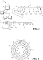
- FIG. 1 illustrates a catheter system 2, in accordance with one embodiment of the present disclosure.
- the catheter system 2 is configured to provide a pressurized fluid (e.g., thrombolytic drugs) at multiple stations for removal or breakdown of thrombus from a vessel such as an artery or vein.
- a pressurized fluid e.g., thrombolytic drugs
- the pressurized fluid penetrates the blood clot more effectively and reduces the procedure time as compared to other methods.
- the thrombolytic drugs delivered to the vessel include, but are not limited to, lytics (e.g., tissue plasminogen activator (tPA)) or other drugs that interact with the thrombus and actively reduce the size (e.g., breakdown, dislodge, minimize or eliminate) the thrombus.
- lytics e.g., tissue plasminogen activator (tPA)
- tPA tissue plasminogen activator
- a thrombectomy catheter is used to further macerate and aspirate any remaining thrombus within the vessel.
- the thrombectomy catheter is used to clear any remaining thrombus.
- thrombectomy catheters are described in Bonnette et al., U.S. Patent Publication No. 2006/0129091 , entitled “ENHANCED CROSS STREAM MECHANICAL THROMBECTOMY CATHETER WITH BACKLOADING MANIFOLD,” Bonnette et al., U.S. Patent No.: 6,676,637 , entitled “SINGLE OPERATOR EXCHANGE FLUID JET THROMBECTOMY METHOD,” and Bonnette et al., U.S. Patent No.: 6,945,951 , entitled “THROMBECTOMY CATHETER AND SYSTEM.”
- the catheter system 2 includes a multi-station hydrodynamic catheter 4 in association with a manifold assembly 18.
- the hydrodynamic catheter 4 includes an outer catheter 22 and an inner catheter 24, where the inner catheter 24 is moveable within the outer catheter 22.
- the outer catheter 22 is coupled to and extends distally from the manifold assembly 18.
- the outer catheter 22 includes a first lumen 32 that extends along a length of the outer catheter 22 (e.g., from a proximal end 21 to a distal end 31)
- the outer catheter 22 includes a plurality of orifice stations 28A-E (collectively referred to as "orifice stations 28") positioned along a portion of the outer catheter 22.
- the portion of the outer catheter 22 that includes the plurality of orifice stations 28 is a distal portion of the outer catheter 22.
- Each orifice station 28 of the plurality of orifice stations 28 includes one or more orifices 30 configured to deliver the pressurized fluid to a vessel.
- the inner catheter 24 includes a second lumen 34 extending along a length of the inner catheter 24.
- the inner catheter 24 is positioned within the first lumen 32 of the outer catheter 22.
- the inner catheter 24 includes at least one emanator 36 including one or more fluid delivery ports 38.
- the inner catheter 24 is movable within the outer catheter 22 such that, at multiple positions within the outer catheter 22, the emanator 36 aligns with each one of the plurality of orifice stations 28. For example, when the emanator 36 is aligned with a first orifice station 28A of the plurality of orifice stations 28, the one or more fluid delivery ports 38 of the emanator 36 are in fluid communication with the one or more orifices 30 of the first orifice station 28A.
- the second lumen 34 is configured to deliver the pressurized fluid to the one or more fluid delivery ports 28 and to the one or more respective orifices 30 of the first orifice station 28A used in a thrombectomy procedure.
- the pressurized fluid within the lumen 34 has pressures including, but not limited to, about 0.34 bar (5 psi) to about 6.9 bar (100 psi).
- the one or more orifices 30 provide corresponding fluid jets at flow rates including, but not limited to, about 1 meter per second (m/s) to about 30 m/s (or a shear rate low enough to not cause appreciable hemolysis).
- the hydrodynamic catheter 4 is inserted into a vessel, such as a vein or artery, and pressurized fluid is delivered to the emanator 36 via the second lumen 34 and subsequently to a first orifice station 28A of the plurality of orifice stations 28.
- the fluid is delivered through one or more orifices 30 of the first orifice station 28A, and is hydrodynamically delivered into the thrombus within the vessel (e.g., by way of fluid pressure, fluid velocity, and fluid flow volume).
- the pressurized fluid e.g., a thrombolytic fluid
- the inner catheter 24 is advanced within the outer catheter 22 such that the emanator 36 is aligned with a second orifice station 28B of the plurality of orifice stations 28.
- a volume of the fluid is delivered to the vessel via the one or more orifices 30 of the second orifice station 28B.
- the inner catheter 24 is advanced within the outer catheter 22 such that the volume of fluid is delivered to the vessel at each orifice station 28A-E of the plurality of orifice stations 28.
- the second orifice station 28B (and the distal orifice stations 28B-28E) are axially spaced from the first orifice station 28A. Accordingly, the fluid is delivered at a localized point by way of each of the orifice stations 28A-E to differing locations within a vessel (or along a large thrombus deposit).
- the manifold assembly 18 can have multiple structures extending therefrom or attached thereto including, but not limited to, the hydrodynamic catheter 4. As shown in FIG. 1 , a strain relief fitting 26 is coupled between the hydrodynamic catheter 4 and the manifold assembly 18. In an example, a proximal end 21 of the outer catheter 22 is secured to the manifold assembly 18. The inner catheter 24 extends through and is moveable within a side port 20. A fluid delivery device 10 can be coupled to the inner catheter 24 and the side port 20 to deliver a pressurized fluid to the fluid delivery ports 38 of the emanator 36.
- the fluid delivery device 10 pumps a volume of a fluid 8 from a fluid reservoir 6 into the second lumen 34 to generate a pressurized source of fluid within the second lumen 34.
- the fluid 8 includes thrombolytic drugs such as lytics, and the pressurized source of fluid generates fluid jets when directed through the one or more orifices 30 of each of the orifice stations 28A-E.
- a contrast injector is used as the fluid delivery device 10. The contrast injector can inject a contrast media into the patient.
- the contrast injector is used in the beginning of the procedure to understand where the clot is and the clots magnitude and at the end of the procedure to verify the thrombus has been sufficiently removed.
- Examples of the fluid delivery device 10 are described in Cowan et al., U.S. Patent No. 7,666,169 , entitled “SYRINGE AND SYRINGE PLUNGERS FOR USE WITH MEDICAL INJECTORS” and Critchlow et al., U.S. Patent No.: 6,520,930 , entitled “INJECTORS, INJECTOR SYSTEMS AND INJECTOR CONTROL”.
- a motor 14 is optionally coupled to the inner catheter 24.
- the motor 14 advances (e.g., moves) the inner catheter 24 within the outer catheter 22 between the plurality of orifice stations 28.
- a control unit 16 is operably coupled with the fluid delivery device 10 and the motor 14.
- the control unit 16 provides one or more of monitoring and control of the motor 14 and corresponding movement of the inner catheter 24 within the outer catheter 22.
- the control unit 16 operates the motor 14 to selectively move the inner catheter 24 from, for example, a first orifice station 28A to a second orifice station 28B.
- control unit 16 operates the fluid delivery device 10 to selectively deliver a volume of the fluid 8 (e.g., a predetermined volume of fluid) over a period of time (e.g., a predetermined period of time), when the multi-station hydrodynamic catheter 4 is at each one of the plurality of orifice stations 28.
- a volume of the fluid 8 e.g., a predetermined volume of fluid
- a period of time e.g., a predetermined period of time
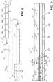
- FIG. 2 illustrates an exploded view of a multi-station hydrodynamic catheter 4, in accordance with one embodiment of the present disclosure.
- the outer catheter 22 includes the plurality of orifice stations 28 positioned along a portion of the outer catheter 22. As illustrated in FIG. 2 , the outer catheter 22 includes five orifice stations 28A-E. Optionally, more or less than five orifice stations 28 are incorporated into the outer catheter 22 in other examples.
- the plurality of orifice stations 28 are symmetrically spaced along a longitudinal axis 42 of the outer catheter 22. In an example, each orifice station 28 is spaced from an adjacent orifice station 28 by a distance 40. In one example, the distance 40 between each of the orifice stations 28 is equal. In another example, the distance 40 between each orifice station 28 varies along the length of the outer catheter 22. In an example, the number and spacing of the orifice stations 28 vary based on one or more of the location and size of the thrombus to be removed, the vascular location of the thrombus or the like.
- the plurality of orifice stations 28 each include one or more orifices 30.
- each orifice station 28 includes four orifices 30 that are radially spaced along a periphery of the outer catheter 22 (e.g., symmetrically spaced around the outer catheter periphery).
- the orifice stations 28 include more or less than four orifices 30.
- the number of orifices 30 at each orifice station 28 can vary between the plurality of orifice stations 28.
- the orifices 30 at each orifice station 28 are generally located on a plane that is perpendicular to the longitudinal axis 42 of the outer catheter 22.
- the orifices 30 of an orifice station 28 are staggered such that the one or more orifices 30 of a particular orifice station 28 are arranged in a non-planar fashion that is substantially perpendicular to the longitudinal axis 42.
- the one or more orifices 30 have a circular shape.
- the one or more orifices 30 can have a number of different shapes.
- the one or more orifices 30 include, but are not limited to, circular, ovular, square, triangular, trapezoidal, polygonal, parallelogram, rhomboidal, and other irregular shapes.
- the outer catheter 22 includes a radiopaque markers 44A-B (collectively "radiopaque markers 44") that are visible when viewed by an imaging device, such as an X-ray machine, a magnetic resonance imaging (MRI) device, a computed tomography (CT) scan, a computed axial tomography (CAT) scan, a positron emission tomography (PET) scan, an ultrasound device or the like.
- an imaging device such as an X-ray machine, a magnetic resonance imaging (MRI) device, a computed tomography (CT) scan, a computed axial tomography (CAT) scan, a positron emission tomography (PET) scan, an ultrasound device or the like.
- CT computed tomography
- CAT computed axial tomography
- PET positron emission tomography
- a first radiopaque marker 44A is positioned proximal to a first orifice station 28A
- a second radiopaque marker 44B is positioned distal to a last orifice station 28E.
- the radiopaque markers 44 provide guidance regarding the positioning of the outer catheter 22 within a vessel.
- the radiopaque markers 44 facilitate the positioning of the plurality of orifice stations 28 along a portion of the vessel including the thrombus.
- the inner catheter 24 shown in FIG. 2 includes at least one emanator 36 having one or more fluid delivery portions 38.
- the at least one emanator 36 is positioned toward a distal portion 56 of the inner catheter 24.
- the inner catheter 24 includes a single emanator 36. In other examples more than one emanator 24 is positioned along the inner catheter 24. Where more than one emanator 24 is used, a distance between each one of the emanators 36 optionally equals the distance 40 between each of the plurality of orifice stations 28.
- the one or more fluid delivery ports 38 have a similar configuration to the one or more orifices 30 such that, when the emanator 36 is aligned with one of the plurality of orifice stations 28, the fluid delivery ports 38 are aligned and in fluid communication with the one or more orifices 30 to deliver the fluid to the vessel.
- the one or more fluid delivery ports 38 are radially spaced along a periphery of the inner catheter 24.
- the number of fluid delivery ports 38 of the emanator 36 equals the number of orifices 30 of each of the orifice stations 28.
- the one or more orifices 30 have a variety of different shapes.
- the one or more fluid delivery ports 38 have a circular, ovular, square, triangular, trapezoidal, polygonal, parallelogram, rhomboidal, or other irregular shape.
- the shape and size of the fluid delivery ports 38 of the emanator 36 are substantially the same as the shape and size of the one or more orifices 30 of the orifice stations 28.
- the shape and size of the fluid delivery ports 38 are different from the shape and size of the one or more orifices 30.
- the inner catheter 24 includes a plurality of station reference markers 46A-E (collectively referred to as "station reference markers 46") positioned along a proximal portion 47 of the inner catheter 24.
- the number of the station reference markers 46 is equal to the number of orifice stations 28 positioned along the outer catheter 22.
- the station reference markers 46 are spaced apart a distance 48 that is substantially the same as the distance 40 between the plurality of orifice stations 28.
- the station reference markers 46 aide an operator to advance the inner catheter 24 from a first orifice station (e.g., orifice station 28A) to a second orifice station (e.g., orifice station 28B) and any other distal orifice station 28.
- the emanator 36 is aligned with a first orifice station 28A.
- the most-proximal station reference marker 46A abuts the proximal end 50 of the outer catheter 22, the emanator 36 is aligned with a last orifice station 28E.
- FIG. 3A illustrates a cross-section of the multi-station hydrodynamic catheter 4 in FIG. 2 .
- the outer catheter 22 includes the plurality of orifice stations 28 positioned along the portion of the outer catheter 22.
- Each orifice station 28 includes one or more orifices 30 extending from an outer catheter external surface 52 to the first lumen 32.
- the inner catheter 24 is positioned within the first lumen 32 of the outer catheter 22.
- the inner catheter 24 includes the at least one emanator 36 including one or more fluid delivery ports 38 extending from an inner catheter external surface 54 to the second lumen 34.
- the inner catheter 24 is moveable within the first lumen 32 and has a diameter such that the inner catheter external surface 54 is adjacent to or in surface-to-surface contact with an outer catheter internal surface 58.
- FIG. 3A further shows the guidewire 12 extending through the second lumen 34 of the inner catheter 24.
- the guidewire 12 facilitates navigation through the vasculature and further allows for sliding movement of the components of the multi-station hydrodynamic catheter 4.
- a distal end 56 of the inner catheter 24 is tapered and contacts the guidewire 12 to form a dynamic seal 60 between the guidewire 12 and the inner catheter 24.
- the dynamic seal 60 substantially closes the second lumen 34 such that the fluid 8 is substantially directed out of the fluid delivery ports 38 of the emanator 36.
- the inner catheter 24 is positioned at a first orifice station 28A.
- the one or more fluid delivery ports 38 of the emanator 36 are in fluid communication with the one or more orifices 30 of the first orifice station 28A of the plurality of orifice stations 28.
- the fluid 8 travels along the second lumen 34, through the fluid delivery ports 38, and through the one or more orifices 30 of the first orifice station 28A to deliver a first fluid jet 62 (or jets with a plurality of orifices 30) to a vessel for hydrodynamic engagement with the thrombus.
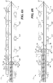
- FIG. 3B illustrates a cross-section of the multi-station hydrodynamic catheter 4 previously shown in FIG. 2 .
- the inner catheter 24 is positioned at a second orifice station 28B of the plurality of orifice stations 28.
- the second orifice station 28B is positioned distal relative to the first orifice station 28A.
- the one or more fluid delivery ports 38 of the emanator 36 are in fluid communication with the one or more orifices 30 of the second orifice station 28B.
- the fluid 8 travels along the second lumen 34, through the fluid delivery ports 38, and through the one or more orifices 30 of the second orifice station 28B to deliver a second fluid jet 64 (or jets with a plurality of orifices 30) to the vessel for hydrodynamic engagement with thrombus.
- the multiple orifice stations 28 of the outer catheter 22 when used in cooperation with the movable inner catheter 24 provide a plurality of fluid jets 62, 64 at varying longitudinal locations along the outer catheter 22. Accordingly, with the outer catheter 22 resting within a thrombus deposit, the inner catheter 24 can move within the lumen 32 longitudinally to provide the fluid jets at varying locations within the thrombus without requiring further navigation or reorientation of the outer catheter 22.
- FIG. 4 illustrates a cross-section of a multi-station hydrodynamic catheter, in accordance with one embodiment of the present disclosure.
- the inner catheter 24 is positioned within the outer catheter 22.
- the outer catheter 22 includes a groove 66 and the inner catheter 24 includes a projection 68.
- the groove 66 extends along a length of the outer catheter 22 and the projection 68 extends along at least a portion of the inner catheter 24.
- the groove 66 is optionally formed between two adjacent orifices 30 and the projection is optionally formed between two adjacent fluid delivery ports 38.
- the groove 66 receives the projection 68 and retains the inner catheter 24 in a substantially aligned configuration with the outer catheter 22.
- the aligned configuration provided by the groove 66 in combination with the projection 68 prevents rotation of the inner catheter 24 relative to the outer catheter 22. Further, the cooperation of the groove 66 and the projection 68 ensures the fluid delivery ports 38 are reliably aligned with corresponding orifices 30 at each of the orifice stations 28 even with repeated reciprocation of the inner catheter 24 within the outer catheter 22.
- the outer catheter 22 includes the projection and the inner catheter 24 includes the groove.
- FIG. 5 illustrates an exploded view of another example of a multi-station hydrodynamic catheter, multi-station hydrodynamic catheter 70, in accordance with one embodiment of the present disclosure.
- the multi-station hydrodynamic catheter 70 includes the outer catheter 22 as described herein with reference to FIGS. 1-4 and an inner catheter 72.
- the outer catheter 22 includes the plurality of orifice stations 28 each including one or more orifices 30 positioned along a portion of the outer catheter 22.
- Each orifice station 28 is spaced from an adjacent orifice station 28 by a distance 40.
- the distance 40 varies between each of the stations.
- the outer catheter 22 includes radiopaque markers 44A-B that are positioned on each side of the plurality of orifice stations 28 facilitating the positioning of the plurality of orifice stations 28 along a portion of the vessel including the thrombus.
- the inner catheter 72 shown in FIG. 5 includes a second lumen 74 and a fluid reservoir 76 (e.g., an exterior fluid reservoir positioned along an exterior of the inner catheter 72 and correspondingly along the interior of the outer catheter 22) positioned toward a distal portion 88 of the inner catheter 72.
- the fluid reservoir 76 (hereinafter referred to interchangeably as "exterior fluid reservoir 76") is in fluid communication with the second lumen 74.
- a proximal sealing shoulder 78 and a distal sealing shoulder 80 form the fluid reservoir 76.
- the inner catheter 72 is moveable within the first lumen 32 of the outer catheter 22 such that, at multiple positions within the outer catheter 22, the fluid reservoir 76 aligns with each one of the plurality of orifice stations 28.
- the fluid reservoir 76 When the fluid reservoir 76 is aligned with a first orifice station 28A of the plurality of orifice stations 28, the fluid reservoir 76 is in fluid communication with the one or more orifices 30 of the first orifice station 28A.
- the second lumen 74 is configured to deliver the pressurized fluid to the fluid reservoir 76 and, by way of the reservoir, to the one or more respective orifices 30 of the first orifice station 28A used in a thrombectomy procedure.
- the one or more orifices 30 of the plurality of orifice stations 28 provide corresponding fluid jets at pressures discussed herein within the lumen 74 for hydrodynamic engagement and removal of thrombus.
- the inner catheter 72 includes a plurality of station reference markers 84A-E (collectively referred to as "station reference markers 84") positioned along a proximal portion 85 of the inner catheter 72.
- the number of the station reference markers 84 equals the number of orifice stations 28 positioned along the outer catheter 22.
- the station reference markers 84 are spaced apart a distance 83 that is substantially the same as the distance 40 between each of the corresponding orifice stations 28.
- the station reference markers 84 aide an operator when advancing the inner catheter 72 to the first orifice station, and from the first orifice station (e.g., orifice station 28A) to a second orifice station (e.g., orifice station 28B).
- the station reference markers 84 assist the operator in accurately positioning the fluid reservoir 76 (e.g., an exterior fluid reservoir positioned along an exterior of the inner catheter 72 and correspondingly along the interior of the outer catheter 22) at any of the orifice stations 28.
- the fluid reservoir 76 e.g., an exterior fluid reservoir positioned along an exterior of the inner catheter 72 and correspondingly along the interior of the outer catheter 22
- the fluid reservoir 76 is aligned with a first orifice station 28A. That is, the fluid reservoir 76 is in fluid communication with the one or more orifices 30 of the first orifice station 28A.
- the fluid reservoir 76 When the most-proximal station reference marker 84A abuts the reference end 50 of the outer catheter 22, the fluid reservoir 76 is aligned with a most-distal orifice station 28E. That is, the fluid reservoir 76 is in fluid communication with the one or more orifices 30 of the orifice station 28E.
- the operator is accordingly able to translate (e.g., "walk") the inner catheter 72 within the outer catheter 22 and accurately position the fluid reservoir 76 at each of the orifice stations 28 without imaging techniques (e.g., fluoroscopy and the like).
- the operator is reliably able to position the reservoir 76 at a plurality of stations 28 and accordingly treat elongate thrombus deposits.
- a diameter 82 of the proximal sealing shoulder 78 and the distal sealing shoulder 80 is greater than a diameter 84 of a cross-section along a portion of the inner catheter 72 proximal to the proximal sealing shoulder 78.
- the diameter 82 of the proximal and distal sealing shoulders 78, 80 have substantially equal diameters.
- the sealing shoulders 78, 80 accordingly close the fluid reservoir and facilitate the movement of the reservoir within the outer catheter 22 while at the same time maintaining the fluid contents of the reservoir therein during movement.
- the remainder of the inner catheter 72 has a smaller diameter 84 than the diameter 84 of the sealing shoulders 78, 80.
- the inner catheter 72 engages in surface to surface contact with the outer catheter 22 at the sealing shoulders 78, 80, and is otherwise free to move within the outer catheter 22.
- the inner catheter 72 in one example, is thereby able to freely translate without friction between a substantial portion of the inner and outer catheters 72, 22.
- FIG. 6A illustrates a cross-section of the multi-station hydrodynamic catheter 70 in FIG. 5 .
- the outer catheter 22 includes the plurality of orifice stations 28 positioned along a portion of the outer catheter 22.
- Each orifice station 28 includes one or more orifices 30 extending from an outer catheter external surface 52 to the first lumen 32.
- the inner catheter 72 is positioned within the first lumen 32 of the outer catheter 22.
- the inner catheter 72 includes the exterior fluid reservoir 76 in fluid communication with the second lumen 74.
- the inner catheter 72 is moveable within the lumen 32 of the outer catheter 22. As illustrated in FIG.
- the proximal and distal sealing shoulders 78, 80 engage (e.g., are in surface to surface contact) with an outer catheter internal surface 58 forming a dynamic seal 92 between the inner catheter 72 and the outer catheter 22.
- the dynamic seal 92 closes the exterior fluid reservoir 76 and assists in directing the fluid 8 through the fluid reservoir 76 toward the one or more orifices 30 of the first orifice station 28A.
- FIG. 6A further shows the guidewire 12 extending through the second lumen 74 of the inner catheter 72.
- the guidewire 12 facilitates navigation through the vasculature and further allows for sliding movement of the components of the multi-station hydrodynamic catheter 70.
- a distal end 88 of the inner catheter 72 is tapered and contacts the guidewire 12 forming a second dynamic seal 90 between the guidewire 12 and the inner catheter 72.
- the second dynamic seal 90 substantially closes the second lumen 72 and assists in directing the fluid 8 through the fluid reservoir 76 toward the one or more orifices 30 of the first orifice station 28A.
- a distal end 94 of the outer catheter 22 is tapered and contacts the guidewire 12 to form a third dynamic seal 96 between the guidewire 12 and the outer catheter 22.
- the dynamic seals 90, 92, 96 assist in guiding the flow of fluid within the multi-station hydrodynamic catheter 70 to the orifices 30 of each of the orifice stations 28. That is to say, the seals 90, 92, 96 cooperate with the fluid reservoir 76 to ensure that fluid is reliably delivered to the orifice stations 28.
- the inner catheter 72 is positioned at a first orifice station 28A.
- the fluid reservoir 76 is in fluid communication with the one or more orifices 30 of the first orifice station 28A.
- the fluid 8 travels along the lumen 74, through the fluid reservoir 76, and by way of the reservoir 76 through the one or more orifices 30 of the first orifice station 28A to deliver one or more first fluid jets 86 to the vessel for hydrodynamic engagement and removal of thrombus.
- FIG. 6B illustrates a cross-section of the multi-station hydrodynamic catheter 70 previously shown in FIG. 5 .
- the inner catheter 72 is translated distally and the fluid reservoir 76 is positioned at a second orifice station 28B of the plurality of orifice stations 28.
- the second orifice station 28B is positioned distally relative to the first orifice station 28A.
- the exterior fluid reservoir 76 is in fluid communication with the one or more orifices 30 of the second orifice station 28B.
- the infusion fluid 8 is delivered along the second lumen 34, through the fluid reservoir 76, and through the one or more orifices 30 of the second orifice station 28B (by way of the reservoir 76) to deliver a second fluid jet 98 to the vessel for hydrodynamic engagement with thrombus.
- the inner catheter 72 includes an fluid reservoir movable within the outer catheter 22 between each of the orifice stations 28. Alignment of the reservoir 76 with each of the orifices 30 at the stations 28 is provided axially (e.g., with the reference marks 84). Radial alignment of the orifices 30 is not needed because (in at least one example) the reservoir 76 forms a ring of infusion fluid around the inner catheter 72 in communication with each of the orifices 30 at each station 28.
- FIG. 7 is a flow chart of an example method 108 which is, however, not claimed.
- a multi-station hydrodynamic catheter is fed into a patient.
- the multi-station hydrodynamic catheter 4 includes an outer catheter 22 having a first lumen 32.
- the outer catheter 22 has a plurality of orifice stations 28A-E positioned along a portion of the outer catheter 22.
- Each orifice station 28 includes one or more orifices 30 extending from an outer catheter external surface 52 to the first lumen 32.
- the multi-station hydrodynamic catheter 4 also includes an inner catheter 24 having a second lumen 34, and the inner catheter 24 is movable within the first lumen 32 between each of the orifice stations of the plurality of orifice stations 28 (e.g., at least first and second orifice stations 28A, B).
- the inner catheter 24 (72) is advanced to a first orifice station within the outer catheter.
- inner catheter 24 is advanced to the first orifice station 28A within the outer catheter 22 as shown in FIG. 3A .
- the fluid delivery ports 38 are in fluid communication with the orifices 30 of the first orifice station 28A.
- advancing the inner catheter 24 (of the multi-station hydrodynamic catheter 4) to the first orifice station 28A includes positioning one or more fluid delivery ports 38 of an emanator 36 of the inner catheter 24 in fluid communication with the one or more orifices 30 of the first orifice station 28A.
- advancing the inner catheter 72 of the multi-station hydrodynamic catheter 70 shown in FIGS. 5 , 6A, B ) to the first orifice station 28A includes positioning the fluid reservoir 76 of the inner catheter 72 in fluid communication with the one or more orifices 30 of the first orifice station 28A.
- a first fluid jet is directed into the vessel at the first orifice station.
- the first fluid jet 62 as shown in FIG. 3A with the multi-station hydrodynamic catheter 4, or the first fluid jet 86, as shown in FIG. 6A with the multi-station hydrodynamic catheter 70, is directed into the vessel at the first fluid orifice station 28A.
- the first fluid orifice station 28A corresponds to a first location of interest (e.g., corresponding to a location of thrombus within the vessel).
- the inner catheter is advanced to a second orifice station 28B within the outer catheter 22.
- the inner catheter 24 is advanced to the second orifice station 28B within the outer catheter 22, as shown in FIG. 3B .
- the fluid delivery ports 38 are in fluid communication with the orifices 30 of the second orifice station 28B.
- one or more projections received within one or more corresponding grooves align the orifices 30 with the fluid delivery ports 38 and accordingly ensure delivery of the infusion fluid at each of the orifice stations 28.
- the fluid reservoir 76 provides a pool or ring of fluid around the exterior of the inner catheter 72 and correspondingly along the interior of the outer catheter 22. Accordingly, the fluid reservoir 76 fluidly communicates automatically with each of the orifices 30 of the second orifice station 28B, as shown in FIG. 6B .
- advancing the inner catheter 24 to the second orifice station 28B within the outer catheter 22 includes operating a motor that advances the inner catheter 24 a distance within the outer catheter 22.
- the motor 14 shown in FIG. 1 advances the inner catheter 24 (72) relative to the outer catheter 22.
- the distance the motor advances the inner catheter 24 equals a distance 40 between the first orifice station 28A and the second orifice station 28B, as shown in FIG. 2 .
- a controller 16 coupled with the motor 14 cooperates with an encoder associated with the inner and outer catheters 22, 24 (22, 72) and advances the inner catheter 24 (72) according to reference markings, such as reference markings 84.
- the controller 16 for the motor 14 is coupled with a translation sensor coupled along the inner catheter and is accordingly able to measure the translation of the inner catheter 24 (72) and arrest movement as the inner catheter 24 (72) is moved into a position corresponding to a desired orifice station 28 of the outer catheter 22.
- a second fluid jet is directed into the vessel at the second orifice station.
- the second fluid jet 64 (as shown in FIG. 3B ) or the second fluid jet 98 (as shown in FIG. 6B ) is directed into the vessel at the second fluid orifice station 28B.
- the second fluid orifice station 28B corresponds to a second location of interest (e.g., corresponding to a location of thrombus within the vessel).
- the multiple orifice stations 28 of the outer catheter 22 when used in cooperation with the movable inner catheter 24 (72) provide a plurality of fluid jets at varying longitudinal locations along the outer catheter 22. According, with the outer catheter 22 resting within a thrombus deposit, the inner catheter 24 (72) can move within the lumen 32 to provide the fluid jets at varying locations within the thrombus without requiring further navigation or reorientation of the outer catheter 22.
- directing includes pumping a volume of fluid into the vessel over a time period.
- a volume of the fluid e.g., a predetermined volume
- the one or more orifices 30 of each of the plurality of orifice stations 30 provide a volume of fluid, including but not limited to, about 0.5 cubic centimeters (cc) to about 5 cc.
- the controller 16 is configured to supply a predetermined volume of infusion fluid (e.g., lytics) at each of the orifice stations 28 for a predetermined time.
- the controller 16 is programmed to translate the inner catheter 24 (72) relative to the outer catheter 22 and accordingly infuse at one or more of the orifice stations 28.
- the operator is able, through the controller 16, to program desired infusion volumes, rates, the order of infusion (e.g., the order of the orifice station 28 infusions).
- the controller 16 operates each of the infusion delivery pump 10 and the motor 14 to accordingly translate and infuse at each of the orifice stations 28 according to the programmed scenario.
- the volume of the fluid delivered to the vessel at each orifice stations 28 is delivered in a single fluid jet.
- the volume of the fluid delivered to the vessel at each orifice station 28 is delivered as a pulsed fluid jet (e.g., in a plurality of pulsed fluid jets in sequence over a time period. In that instance, each pulse is spaced apart by a time interval within a specified time period.
- 2 cc is delivered to a vessel in pulsed fluid jets, where the fluid jets are spaced apart by 20 minutes.
- flow rates including but not limited to about 1 m/s to about 30 m/s are used to provide the fluid jets to the vessel through the one or more orifices 30 of the plurality of orifice stations 28.
- the fluid jets are provided to the vessel having flow rates, including but not limited to about 10 m/s to 20 m/s.
- the fluid jets are provided to the vessel having flow rates, including but not limited to about 15 cc/s.
- the velocity of and flow rate of the fluid jets delivered from the one or more orifices 30 of the plurality of orifice stations 28 is dependent on the flow rate and pressure of the fluid source, the size and shape of the fluid delivery ports 28, the size and shape of the fluid reservoir 76, and the one or more orifices 30 of each orifice station 28.
- the multi-station hydrodynamic catheters 4, 70, described herein, provide a catheter system configured to provide a pressurized fluid (e.g., fluid jets) at multiple orifice stations 28 for removal of a thrombus from a vessel. By providing the direct pressurized fluid delivery along the multiple orifice stations 28, the fluid jets penetrate the blood clot more effectively and reduce the procedure time as compared to other methods.
- the fluid jets at each of the orifice stations 28 localize the delivery of fluid, such as, lytics at locations along a vessel (for instance at longitudinally varied locations of a thrombus deposit).
- the inner catheter 24, 72 is translated from orifice station to orifice station 28 and accordingly provides localized acute treatment to the thrombus at each of the corresponding stations 28.
- the method 108 prior to feeding a multi-station hydrodynamic catheter into the patient, includes feeding a guidewire into the patient to a position within a vessel, such as the guidewire 12 in FIGS. 3A and 3B .
- the method 108 includes removing, prior to directing the first fluid jet, the guidewire, such as guidewire 12 in FIGS. 3A and 3B .
- the guidewire such as guidewire 12 in FIGS. 3A and 3B .
- the method 108 includes removing, prior to directing the first fluid jet, the guidewire, such as guidewire 12 in FIGS. 3A and 3B .
- the guidewire enhanced fluid flow is realized as the lumen 34 (74) of the inner catheter 24 (72) is vacant and accordingly able to deliver additional infusion fluid.
- FIG. 8 illustrates the method 108, again, no method is claimed.
- the method 108 as illustrated in FIG. 8 uses the multi-station hydrodynamic catheter 4, as shown in FIGS. 1-4 for treating a blood clot (e.g., thrombus 124) along multiple stations (e.g., the plurality of orifice stations 28).
- a blood clot e.g., thrombus 124
- the thrombus 124 is treated in multiple steps along the length of the thrombus 124, where at each step (e.g., an orifice station 28) a fluid jet is delivered into the vessel to locally treat (and optionally remove or penetrate) the thrombus 124.
- the multi-station hydrodynamic catheter 4 is positioned within a lumen 120 of a vessel 120 including the thrombus 124.
- the multi-station hydrodynamic catheter 4 includes the internal catheter 24 positioned within the lumen 32 of the outer catheter 22.
- the guidewire 12 is not shown in FIG. 8 . However, as discussed herein, the guidewire 12 may or may not be present during the thrombectomy treatment.
- the multi-station hydrodynamic catheter 4 delivers a plurality of fluid jets 126A-E (collectively referred to as "fluid jets 126") to the thrombus deposit 124.
- the inner catheter 24 is advanced ("walked") to each of the orifice stations 28 within the thrombus to provide directed localized treatment to the thrombus deposit at each location.
- the fluid 8 more effectively treats the entire deposit (e.g., penetrates, locally delivers treatment such as lytics, removes thrombus through hydrodynamic engagement or the like) and reduces the procedure time as compared to other methods.
- the operator is able to leave the outer catheter 22 at a static location and gradually move the inner catheter 24 (72) as needed to each of the stations 28 without otherwise disturbing the outer catheter and treatment region. Additionally, the operator may leave the outer catheter 22 in place after a procedure, and another technician (physician, nurse and the like) may advance or retract the inner catheter 24 (72) as needed to treat the thrombus deposit 124.
- the multi-station hydrodynamic catheter 4 has delivered a first fluid jet 126A of the fluid 8 to the vessel 122 (including the thrombus 124) at the first orifice station 28A at time (T).
- a volume of the fluid 8 is delivered to the vessel 122 at the first orifice station 28A by either a single fluid jet 126A or a plurality of fluid jets 126A (e.g., timed pulses of fluid 8).
- the multi-station hydrodynamic catheter 4 is advanced to a second orifice station 28B.
- a second fluid jet 126B of the fluid 8 is directed to the vessel 122 at the second orifice station 28B at time (T n ), where "n" is a time interval after the first fluid jet 126A has been delivered to the vessel 122.
- the multi-station hydrodynamic catheter 4 is advanced to the most-distal orifice station 28E, where a last fluid jet 126E is delivered to the vessel 122 at time (T n+3 ).
- the direct pressurized delivery of the fluid along multiple orifice stations 28A-E penetrates the thrombus 124 more effectively (accordingly removing thrombus effectively) and reduces the procedure time as compared to other methods. Since the fluid 8 engages directly with the entirety of the thrombus and at high pressure (according to the use of the orifice stations 28) the amount of time for the fluid 8 to interact with the thrombus 124 (hydrodynamically or chemically) is reduced, thereby enhancing the efficiency of the thrombectomy technique. Thus, the present subject matter reduces the procedure times and enhances the effectiveness of thrombectomy with thrombus deposits that benefit from multi-station treatment.
Landscapes
- Health & Medical Sciences (AREA)
- Life Sciences & Earth Sciences (AREA)
- Public Health (AREA)
- Veterinary Medicine (AREA)
- Biomedical Technology (AREA)
- Heart & Thoracic Surgery (AREA)
- General Health & Medical Sciences (AREA)
- Engineering & Computer Science (AREA)
- Animal Behavior & Ethology (AREA)
- Hematology (AREA)
- Anesthesiology (AREA)
- Vascular Medicine (AREA)
- Surgery (AREA)
- Pulmonology (AREA)
- Biophysics (AREA)
- Medical Informatics (AREA)
- Molecular Biology (AREA)
- Nuclear Medicine, Radiotherapy & Molecular Imaging (AREA)
- Orthopedic Medicine & Surgery (AREA)
- Surgical Instruments (AREA)
- Media Introduction/Drainage Providing Device (AREA)
- Infusion, Injection, And Reservoir Apparatuses (AREA)
Description
- This document pertains generally, but not by way of limitation, to a catheter system configured to remove blockage within a patient's vessel.
- A thrombectomy is a medical procedure used to remove a blood clot (e.g., thrombus) from a vessel, such as an artery or vein. If a thrombus is not removed, it may obstruct blood flow. In one technique, the thrombus can be removed by a thrombectomy procedure such as thrombolysis which is the breakdown of a thrombus by pharmacological means. Thrombolysis can introduce thrombolytic drugs to the site of the blood clot. The thrombolytic drugs can interact with the thrombus and actively reduce the size (e.g., breakdown, dislodge, minimize, or eliminate) the thrombus.
-
US 2010/0198137 A1 discloses a method for delivering at least one medium to a subject using a catheter device, wherein said method comprises inserting an outer tube into the subject. The outer tube has a distal end and a proximal end and comprises at least one aperture there between. The method further comprises disposing an inner tube within said outer tube. The inner tube has a distal end and a proximal end and comprises at least one aperture there between. The method further comprises providing the at least one medium into said inner tube, and aligning said outer tube aperture and said inner tube aperture to allow the at least one medium to travel through said inner tube aperture and outer tube aperture to the subject while controlling the medium from traveling between the exterior of said inner tube and interior of said outer tube. -
US 2007/0213671 A1 discloses an infusion catheter system that includes an elongated catheter body and an inner elongated cannula body. The catheter body has a sidewall perforated with a plurality of side ports and the cannula body may have an outlet opening in a distal end. The side ports of the catheter body are selectively in fluid communication with the outlet opening of the cannula by moving the cannula between a first and second position within the catheter body. -
WO 2013/019947 A2 ,GB 2 484 598 AUS 5,324,259 A ,US 7,935,092 B1 ,US 2011/0015564 A1 andUS 5,425,723 A disclose catheters.US 2011/0257622 A1 discloses an apparatus for releasing fluid within a patient's body.US 2005/0197663 A1 discloses a guidewire inserter. - The present invention is defined by the claims.
- The present inventors have recognized, among other things, that a problem to be solved includes decreasing a thrombectomy procedure time without sacrificing the effectiveness of the procedure. For example, existing systems and methods for performing a thrombectomy procedure can include weeping thrombolytic drugs to the site of a blood clot over many hours or days (e.g., overnight to about three days). Weeping can include exuding a thrombolytic drug into the blood vessel at the blood clot site at low pressure (e.g., below 0.28 bar (4 pounds per square inch (psi))). Weeping the thrombolytic drugs into the blood vessel does not provide deep penetration into the blood clot and can increase the time for the thrombolytic drugs to interact with the portion of the blood clot adjacent to a blood vessel wall. That is, the thrombolytic drugs introduced via weeping may interact with a surface of the blood clot initially, and over time may come into contact with the portion of the blood clot adjacent to the blood vessel wall.
- The present subject matter provides a solution to this problem, by providing a catheter system that quickly and effectively treats a blood clot.
- The present subject matter reduces the procedure time and enhances the effectiveness of thrombectomy. The present invention is defined by the features of the claims.
- According to the present invention there is provided a catheter system comprising: a multi-station hydrodynamic catheter including: an outer catheter having a first lumen, the outer catheter having a plurality of orifice stations positioned along a portion of the outer catheter, wherein each orifice station includes one or more orifices extending from an outer catheter external surface to the first lumen; and an inner catheter having a second lumen, the inner catheter having a diameter such that an external surface of the inner catheter is in surface-to-surface contact with an internal surface of the outer catheter, the inner catheter movable within the first lumen and includes at least one emanator, wherein the at least one emanator includes one or more fluid delivery ports extending from the inner catheter external surface to the second lumen, the inner catheter movable within the first lumen between a first orifice station and a second orifice station of the plurality of orifice stations, wherein at the first orifice station, the one or more fluid delivery ports of the emanator are in fluid communication with the one or more orifices of the first orifice station of the plurality of orifice stations, and at the second orifice station, the one or more fluid delivery ports of the emanator are in fluid communication with the one or more orifices of a second orifice station of the plurality of orifice stations, the second orifice station positioned distally relative to the first orifice station, and wherein the one or more orifices at the first orifice station are configured to generate a first fluid jet and the one or more orifices at the second orifice station are configured to generate a second fluid jet distal to the first fluid jet.
- The catheter system of the present disclosure provides for treating a blood clot along multiple stations (e.g., the plurality of orifice stations). At the first orifice station a first fluid jet can be pumped into the vessel and then advanced to the second orifice station where a second fluid jet can then be pumped into the vessel. That is, the blood clot can be treated in multiple steps along the length of the clot, where at each step (e.g., an orifice station) a fluid jet is pumped into the vessel. By providing the direct pressurized delivery along multiple orifice stations, the fluid penetrates the blood clot more effectively and reduces the procedure time as compared to other methods. For example, the direct pressurized delivery facilitates the fluid to initially interact with a portion of the blood clot adjacent to a blood vessel upon introduction of the fluid jet. Since the fluid comes into contact with the portion of the blood clot adjacent to the blood vessel wall initially, the amount of time for the fluid to interact with the blood clot is reduced, thereby enhancing the efficiency of the thrombectomy technique. Thus, the present subject matter can provide for reducing the procedure time and enhancing the effectiveness of thrombectomy.
- This overview
is not intended to provide an exclusive or exhaustive explanation of the invention. - In the drawings, which are not necessarily drawn to scale, like numerals may describe similar components in different views. Like numerals having different letter suffixes may represent different instances of similar components. The drawings illustrate generally, by way of example, but not by way of limitation, various embodiments discussed in the present document.
-
FIG. 1 illustrates a catheter system, in accordance with one embodiment of the present disclosure. -
FIG. 2 illustrates an exploded view of a multi-station hydrodynamic catheter, in accordance with one embodiment of the present disclosure. -
FIG. 3A illustrates a cross-section of the multi-station hydrodynamic catheter inFIG. 2 infusing at a first orifice station. -
FIG. 3B illustrates a cross-section of the multi-station hydrodynamic catheter inFIG. 2 infusing at a second orifice station. -
FIG. 4 illustrates a cross-section of a multi-station hydrodynamic catheter, in accordance with one embodiment of the present disclosure. -
FIG. 5 illustrates an exploded view of a multi-station hydrodynamic catheter, in accordance with one embodiment of the present disclosure. -
FIG. 6A illustrates a cross-section of the multi-station hydrodynamic catheter inFIG. 5 infusing at a first orifice station. -
FIG. 6B illustrates a cross-section of the multi-station hydrodynamic catheter inFIG. 5 infusing at a second orifice station. -
FIG. 7 is a flow chart showing an example method. Note that no method is claimed. -
FIG. 8 illustrates the method as depicted infigure 7 . -
FIG. 1 illustrates acatheter system 2, in accordance with one embodiment of the present disclosure. As will be described in detail herein, thecatheter system 2 is configured to provide a pressurized fluid (e.g., thrombolytic drugs) at multiple stations for removal or breakdown of thrombus from a vessel such as an artery or vein. By providing direct pressurized fluid delivery along the multiple stations, the pressurized fluid penetrates the blood clot more effectively and reduces the procedure time as compared to other methods. In one example, the thrombolytic drugs delivered to the vessel include, but are not limited to, lytics (e.g., tissue plasminogen activator (tPA)) or other drugs that interact with the thrombus and actively reduce the size (e.g., breakdown, dislodge, minimize or eliminate) the thrombus. In some examples, after thecatheter system 2 delivers the lytics or other drugs to actively reduce the size of the thrombus, a thrombectomy catheter is used to further macerate and aspirate any remaining thrombus within the vessel. For example, oncecatheter system 2 has treated the thrombus with the lytics or other drugs, the thrombectomy catheter is used to clear any remaining thrombus. In an example, using thecatheter system 2 in combination with a thrombectomy catheter can reduce the overall procedure time. Examples of thrombectomy catheters are described inBonnette et al., U.S. Patent Publication No. 2006/0129091 , entitled "ENHANCED CROSS STREAM MECHANICAL THROMBECTOMY CATHETER WITH BACKLOADING MANIFOLD,"Bonnette et al., U.S. Patent No.: 6,676,637 , entitled "SINGLE OPERATOR EXCHANGE FLUID JET THROMBECTOMY METHOD," andBonnette et al., U.S. Patent No.: 6,945,951 , entitled "THROMBECTOMY CATHETER AND SYSTEM." - In an example, the
catheter system 2 includes a multi-stationhydrodynamic catheter 4 in association with amanifold assembly 18. Thehydrodynamic catheter 4 includes anouter catheter 22 and aninner catheter 24, where theinner catheter 24 is moveable within theouter catheter 22. In an example, theouter catheter 22 is coupled to and extends distally from themanifold assembly 18. Theouter catheter 22 includes afirst lumen 32 that extends along a length of the outer catheter 22 (e.g., from aproximal end 21 to a distal end 31) In an example, theouter catheter 22 includes a plurality oforifice stations 28A-E (collectively referred to as "orifice stations 28") positioned along a portion of theouter catheter 22. In an example, the portion of theouter catheter 22 that includes the plurality of orifice stations 28 is a distal portion of theouter catheter 22. Each orifice station 28 of the plurality of orifice stations 28 includes one ormore orifices 30 configured to deliver the pressurized fluid to a vessel. - In an example, the
inner catheter 24 includes asecond lumen 34 extending along a length of theinner catheter 24. Theinner catheter 24 is positioned within thefirst lumen 32 of theouter catheter 22. Theinner catheter 24 includes at least oneemanator 36 including one or morefluid delivery ports 38. As discussed herein, theinner catheter 24 is movable within theouter catheter 22 such that, at multiple positions within theouter catheter 22, theemanator 36 aligns with each one of the plurality of orifice stations 28. For example, when theemanator 36 is aligned with afirst orifice station 28A of the plurality of orifice stations 28, the one or morefluid delivery ports 38 of theemanator 36 are in fluid communication with the one ormore orifices 30 of thefirst orifice station 28A. As shown inFigure 2 , thesecond lumen 34 is configured to deliver the pressurized fluid to the one or more fluid delivery ports 28 and to the one or morerespective orifices 30 of thefirst orifice station 28A used in a thrombectomy procedure. In an example, the pressurized fluid within thelumen 34 has pressures including, but not limited to, about 0.34 bar (5 psi) to about 6.9 bar (100 psi). In an example, the one ormore orifices 30 provide corresponding fluid jets at flow rates including, but not limited to, about 1 meter per second (m/s) to about 30 m/s (or a shear rate low enough to not cause appreciable hemolysis). - In operation, the
hydrodynamic catheter 4 is inserted into a vessel, such as a vein or artery, and pressurized fluid is delivered to theemanator 36 via thesecond lumen 34 and subsequently to afirst orifice station 28A of the plurality of orifice stations 28. The fluid is delivered through one ormore orifices 30 of thefirst orifice station 28A, and is hydrodynamically delivered into the thrombus within the vessel (e.g., by way of fluid pressure, fluid velocity, and fluid flow volume). For instance, the pressurized fluid (e.g., a thrombolytic fluid) impacts and penetrates the thrombus local to thefirst orifice station 28A and actively reduces the size (e.g., breaks down) and minimizes or eliminates the thrombus. - As discussed below, after a volume of the fluid is delivered to the vessel via the one or
more orifices 30 of the first orifice station 28, theinner catheter 24 is advanced within theouter catheter 22 such that theemanator 36 is aligned with asecond orifice station 28B of the plurality of orifice stations 28. When aligned with thesecond orifice station 28B, a volume of the fluid is delivered to the vessel via the one ormore orifices 30 of thesecond orifice station 28B. Theinner catheter 24 is advanced within theouter catheter 22 such that the volume of fluid is delivered to the vessel at eachorifice station 28A-E of the plurality of orifice stations 28. As is shown inFigure 2 , thesecond orifice station 28B (and thedistal orifice stations 28B-28E) are axially spaced from thefirst orifice station 28A. Accordingly, the fluid is delivered at a localized point by way of each of theorifice stations 28A-E to differing locations within a vessel (or along a large thrombus deposit). - In an example, the
manifold assembly 18 can have multiple structures extending therefrom or attached thereto including, but not limited to, thehydrodynamic catheter 4. As shown inFIG. 1 , a strain relief fitting 26 is coupled between thehydrodynamic catheter 4 and themanifold assembly 18. In an example, aproximal end 21 of theouter catheter 22 is secured to themanifold assembly 18. Theinner catheter 24 extends through and is moveable within aside port 20. Afluid delivery device 10 can be coupled to theinner catheter 24 and theside port 20 to deliver a pressurized fluid to thefluid delivery ports 38 of theemanator 36. The fluid delivery device 10 (e.g., a pump or injector) pumps a volume of a fluid 8 from afluid reservoir 6 into thesecond lumen 34 to generate a pressurized source of fluid within thesecond lumen 34. In an example, thefluid 8 includes thrombolytic drugs such as lytics, and the pressurized source of fluid generates fluid jets when directed through the one ormore orifices 30 of each of theorifice stations 28A-E. In an example, a contrast injector is used as thefluid delivery device 10. The contrast injector can inject a contrast media into the patient. In an example, the contrast injector is used in the beginning of the procedure to understand where the clot is and the clots magnitude and at the end of the procedure to verify the thrombus has been sufficiently removed. Examples of thefluid delivery device 10 are described inCowan et al., U.S. Patent No. 7,666,169 , entitled "SYRINGE AND SYRINGE PLUNGERS FOR USE WITH MEDICAL INJECTORS" andCritchlow et al., U.S. Patent No.: 6,520,930 , entitled "INJECTORS, INJECTOR SYSTEMS AND INJECTOR CONTROL". - Referring again to
FIG. 1 , amotor 14 is optionally coupled to theinner catheter 24. Themotor 14 advances (e.g., moves) theinner catheter 24 within theouter catheter 22 between the plurality of orifice stations 28. Acontrol unit 16 is operably coupled with thefluid delivery device 10 and themotor 14. In an example, thecontrol unit 16 provides one or more of monitoring and control of themotor 14 and corresponding movement of theinner catheter 24 within theouter catheter 22. For example, thecontrol unit 16 operates themotor 14 to selectively move theinner catheter 24 from, for example, afirst orifice station 28A to asecond orifice station 28B. Additionally, thecontrol unit 16 operates thefluid delivery device 10 to selectively deliver a volume of the fluid 8 (e.g., a predetermined volume of fluid) over a period of time (e.g., a predetermined period of time), when the multi-stationhydrodynamic catheter 4 is at each one of the plurality of orifice stations 28. -
FIG. 2 illustrates an exploded view of a multi-stationhydrodynamic catheter 4, in accordance with one embodiment of the present disclosure. - The
outer catheter 22 includes the plurality of orifice stations 28 positioned along a portion of theouter catheter 22. As illustrated inFIG. 2 , theouter catheter 22 includes fiveorifice stations 28A-E. Optionally, more or less than five orifice stations 28 are incorporated into theouter catheter 22 in other examples. The plurality of orifice stations 28 are symmetrically spaced along alongitudinal axis 42 of theouter catheter 22. In an example, each orifice station 28 is spaced from an adjacent orifice station 28 by a distance 40. In one example, the distance 40 between each of the orifice stations 28 is equal. In another example, the distance 40 between each orifice station 28 varies along the length of theouter catheter 22. In an example, the number and spacing of the orifice stations 28 vary based on one or more of the location and size of the thrombus to be removed, the vascular location of the thrombus or the like. - As illustrated in
FIG. 2 , the plurality of orifice stations 28 each include one or more orifices 30. In an example, each orifice station 28 includes fourorifices 30 that are radially spaced along a periphery of the outer catheter 22 (e.g., symmetrically spaced around the outer catheter periphery). In an example, the orifice stations 28 include more or less than fourorifices 30. In another example, the number oforifices 30 at each orifice station 28 can vary between the plurality of orifice stations 28. As illustrated inFIG. 2 , theorifices 30 at each orifice station 28 are generally located on a plane that is perpendicular to thelongitudinal axis 42 of theouter catheter 22. In still another example, theorifices 30 of an orifice station 28 are staggered such that the one ormore orifices 30 of a particular orifice station 28 are arranged in a non-planar fashion that is substantially perpendicular to thelongitudinal axis 42. - As illustrated in
FIG. 2 , the one ormore orifices 30 have a circular shape. In an example, the one ormore orifices 30 can have a number of different shapes. For example, the one ormore orifices 30 include, but are not limited to, circular, ovular, square, triangular, trapezoidal, polygonal, parallelogram, rhomboidal, and other irregular shapes. - In another example, the
outer catheter 22 includes aradiopaque markers 44A-B (collectively "radiopaque markers 44") that are visible when viewed by an imaging device, such as an X-ray machine, a magnetic resonance imaging (MRI) device, a computed tomography (CT) scan, a computed axial tomography (CAT) scan, a positron emission tomography (PET) scan, an ultrasound device or the like. In an example, the radiopaque markers 44 are positioned on each side of the plurality of orifice stations 28. For example, a firstradiopaque marker 44A is positioned proximal to afirst orifice station 28A, a secondradiopaque marker 44B is positioned distal to alast orifice station 28E. The radiopaque markers 44 provide guidance regarding the positioning of theouter catheter 22 within a vessel. For example, the radiopaque markers 44 facilitate the positioning of the plurality of orifice stations 28 along a portion of the vessel including the thrombus. - The
inner catheter 24 shown inFIG. 2 includes at least oneemanator 36 having one or morefluid delivery portions 38. The at least oneemanator 36 is positioned toward adistal portion 56 of theinner catheter 24. As illustrated inFIG. 2 , theinner catheter 24 includes asingle emanator 36. In other examples more than oneemanator 24 is positioned along theinner catheter 24. Where more than oneemanator 24 is used, a distance between each one of theemanators 36 optionally equals the distance 40 between each of the plurality of orifice stations 28. - In the configuration shown in
Figure 2 , the one or morefluid delivery ports 38 have a similar configuration to the one ormore orifices 30 such that, when theemanator 36 is aligned with one of the plurality of orifice stations 28, thefluid delivery ports 38 are aligned and in fluid communication with the one ormore orifices 30 to deliver the fluid to the vessel. For example, similar to theorifices 30 of the plurality of orifice stations 28, the one or morefluid delivery ports 38 are radially spaced along a periphery of theinner catheter 24. In an example, the number offluid delivery ports 38 of theemanator 36 equals the number oforifices 30 of each of the orifice stations 28. In an example, the one ormore orifices 30 have a variety of different shapes. For example, the one or morefluid delivery ports 38 have a circular, ovular, square, triangular, trapezoidal, polygonal, parallelogram, rhomboidal, or other irregular shape. In an example, the shape and size of thefluid delivery ports 38 of theemanator 36 are substantially the same as the shape and size of the one ormore orifices 30 of the orifice stations 28. In another example, the shape and size of thefluid delivery ports 38 are different from the shape and size of the one or more orifices 30. - Optionally, the
inner catheter 24 includes a plurality ofstation reference markers 46A-E (collectively referred to as "station reference markers 46") positioned along aproximal portion 47 of theinner catheter 24. In the example shown, the number of the station reference markers 46 is equal to the number of orifice stations 28 positioned along theouter catheter 22. The station reference markers 46 are spaced apart adistance 48 that is substantially the same as the distance 40 between the plurality of orifice stations 28. The station reference markers 46 aide an operator to advance theinner catheter 24 from a first orifice station (e.g.,orifice station 28A) to a second orifice station (e.g.,orifice station 28B) and any other distal orifice station 28. In an example, when the most-distalstation reference marker 46E abuts areference portion 50 of theouter catheter 22, theemanator 36 is aligned with afirst orifice station 28A. When the most-proximalstation reference marker 46A abuts theproximal end 50 of theouter catheter 22, theemanator 36 is aligned with alast orifice station 28E. -
FIG. 3A illustrates a cross-section of the multi-stationhydrodynamic catheter 4 inFIG. 2 . As illustrated inFIG. 3A , theouter catheter 22 includes the plurality of orifice stations 28 positioned along the portion of theouter catheter 22. Each orifice station 28 includes one ormore orifices 30 extending from an outer catheterexternal surface 52 to thefirst lumen 32. Theinner catheter 24 is positioned within thefirst lumen 32 of theouter catheter 22. Theinner catheter 24 includes the at least oneemanator 36 including one or morefluid delivery ports 38 extending from an inner catheterexternal surface 54 to thesecond lumen 34. Theinner catheter 24 is moveable within thefirst lumen 32 and has a diameter such that the inner catheterexternal surface 54 is adjacent to or in surface-to-surface contact with an outer catheterinternal surface 58. -
FIG. 3A further shows theguidewire 12 extending through thesecond lumen 34 of theinner catheter 24. Theguidewire 12 facilitates navigation through the vasculature and further allows for sliding movement of the components of the multi-stationhydrodynamic catheter 4. In an example, adistal end 56 of theinner catheter 24 is tapered and contacts theguidewire 12 to form adynamic seal 60 between theguidewire 12 and theinner catheter 24. Thedynamic seal 60 substantially closes thesecond lumen 34 such that thefluid 8 is substantially directed out of thefluid delivery ports 38 of theemanator 36. - As illustrated in
FIG. 3A , theinner catheter 24 is positioned at afirst orifice station 28A. At thefirst orifice station 28A, the one or morefluid delivery ports 38 of theemanator 36 are in fluid communication with the one ormore orifices 30 of thefirst orifice station 28A of the plurality of orifice stations 28. Thefluid 8 travels along thesecond lumen 34, through thefluid delivery ports 38, and through the one ormore orifices 30 of thefirst orifice station 28A to deliver a first fluid jet 62 (or jets with a plurality of orifices 30) to a vessel for hydrodynamic engagement with the thrombus. -
FIG. 3B illustrates a cross-section of the multi-stationhydrodynamic catheter 4 previously shown inFIG. 2 . As illustrated inFIG. 3B , theinner catheter 24 is positioned at asecond orifice station 28B of the plurality of orifice stations 28. Thesecond orifice station 28B is positioned distal relative to thefirst orifice station 28A. At thesecond orifice station 28B, the one or morefluid delivery ports 38 of theemanator 36 are in fluid communication with the one ormore orifices 30 of thesecond orifice station 28B. Thefluid 8 travels along thesecond lumen 34, through thefluid delivery ports 38, and through the one ormore orifices 30 of thesecond orifice station 28B to deliver a second fluid jet 64 (or jets with a plurality of orifices 30) to the vessel for hydrodynamic engagement with thrombus. The multiple orifice stations 28 of theouter catheter 22 when used in cooperation with the movableinner catheter 24 provide a plurality offluid jets outer catheter 22. Accordingly, with theouter catheter 22 resting within a thrombus deposit, theinner catheter 24 can move within thelumen 32 longitudinally to provide the fluid jets at varying locations within the thrombus without requiring further navigation or reorientation of theouter catheter 22. -
FIG. 4 illustrates a cross-section of a multi-station hydrodynamic catheter, in accordance with one embodiment of the present disclosure. As illustrated inFIG. 4 , theinner catheter 24 is positioned within theouter catheter 22. In an example, theouter catheter 22 includes agroove 66 and theinner catheter 24 includes aprojection 68. Thegroove 66 extends along a length of theouter catheter 22 and theprojection 68 extends along at least a portion of theinner catheter 24. Thegroove 66 is optionally formed between twoadjacent orifices 30 and the projection is optionally formed between two adjacentfluid delivery ports 38. Thegroove 66 receives theprojection 68 and retains theinner catheter 24 in a substantially aligned configuration with theouter catheter 22. The aligned configuration provided by thegroove 66 in combination with theprojection 68 prevents rotation of theinner catheter 24 relative to theouter catheter 22. Further, the cooperation of thegroove 66 and theprojection 68 ensures thefluid delivery ports 38 are reliably aligned withcorresponding orifices 30 at each of the orifice stations 28 even with repeated reciprocation of theinner catheter 24 within theouter catheter 22. In another example, theouter catheter 22 includes the projection and theinner catheter 24 includes the groove. -
FIG. 5 illustrates an exploded view of another example of a multi-station hydrodynamic catheter, multi-stationhydrodynamic catheter 70, in accordance with one embodiment of the present disclosure. The multi-stationhydrodynamic catheter 70 includes theouter catheter 22 as described herein with reference toFIGS. 1-4 and aninner catheter 72. As discussed herein, theouter catheter 22 includes the plurality of orifice stations 28 each including one ormore orifices 30 positioned along a portion of theouter catheter 22. Each orifice station 28 is spaced from an adjacent orifice station 28 by a distance 40. Optionally, the distance 40 varies between each of the stations. In a similar manner to theouter catheter 22 previously described above, theouter catheter 22 includesradiopaque markers 44A-B that are positioned on each side of the plurality of orifice stations 28 facilitating the positioning of the plurality of orifice stations 28 along a portion of the vessel including the thrombus. - The
inner catheter 72 shown inFIG. 5 includes asecond lumen 74 and a fluid reservoir 76 (e.g., an exterior fluid reservoir positioned along an exterior of theinner catheter 72 and correspondingly along the interior of the outer catheter 22) positioned toward adistal portion 88 of theinner catheter 72. The fluid reservoir 76 (hereinafter referred to interchangeably as "exterior fluid reservoir 76") is in fluid communication with thesecond lumen 74. In an example, a proximal sealingshoulder 78 and adistal sealing shoulder 80 form the fluid reservoir 76. Theinner catheter 72 is moveable within thefirst lumen 32 of theouter catheter 22 such that, at multiple positions within theouter catheter 22, the fluid reservoir 76 aligns with each one of the plurality of orifice stations 28. When the fluid reservoir 76 is aligned with afirst orifice station 28A of the plurality of orifice stations 28, the fluid reservoir 76 is in fluid communication with the one ormore orifices 30 of thefirst orifice station 28A. As shown inFigure 5 , thesecond lumen 74 is configured to deliver the pressurized fluid to the fluid reservoir 76 and, by way of the reservoir, to the one or morerespective orifices 30 of thefirst orifice station 28A used in a thrombectomy procedure. As discussed herein, the one ormore orifices 30 of the plurality of orifice stations 28 provide corresponding fluid jets at pressures discussed herein within thelumen 74 for hydrodynamic engagement and removal of thrombus. - Optionally, the
inner catheter 72 includes a plurality ofstation reference markers 84A-E (collectively referred to as "station reference markers 84") positioned along aproximal portion 85 of theinner catheter 72. In the example shown, the number of thestation reference markers 84 equals the number of orifice stations 28 positioned along theouter catheter 22. Thestation reference markers 84 are spaced apart adistance 83 that is substantially the same as the distance 40 between each of the corresponding orifice stations 28. Thestation reference markers 84 aide an operator when advancing theinner catheter 72 to the first orifice station, and from the first orifice station (e.g.,orifice station 28A) to a second orifice station (e.g.,orifice station 28B). In a similar manner, thestation reference markers 84 assist the operator in accurately positioning the fluid reservoir 76 (e.g., an exterior fluid reservoir positioned along an exterior of theinner catheter 72 and correspondingly along the interior of the outer catheter 22) at any of the orifice stations 28. In an example, when the most-distalstation reference marker 84E abuts areference portion 50 of theouter catheter 22, the fluid reservoir 76 is aligned with afirst orifice station 28A. That is, the fluid reservoir 76 is in fluid communication with the one ormore orifices 30 of thefirst orifice station 28A. When the most-proximalstation reference marker 84A abuts thereference end 50 of theouter catheter 22, the fluid reservoir 76 is aligned with a most-distal orifice station 28E. That is, the fluid reservoir 76 is in fluid communication with the one ormore orifices 30 of theorifice station 28E. The operator is accordingly able to translate (e.g., "walk") theinner catheter 72 within theouter catheter 22 and accurately position the fluid reservoir 76 at each of the orifice stations 28 without imaging techniques (e.g., fluoroscopy and the like). Instead, by aligning the respective reference marks 84 with a corresponding marker, such as the proximal end of theouter catheter 22, the operator is reliably able to position the reservoir 76 at a plurality of stations 28 and accordingly treat elongate thrombus deposits. - As illustrated in
FIG. 5 adiameter 82 of the proximal sealingshoulder 78 and thedistal sealing shoulder 80 is greater than adiameter 84 of a cross-section along a portion of theinner catheter 72 proximal to the proximal sealingshoulder 78. In an example, thediameter 82 of the proximal and distal sealing shoulders 78, 80 have substantially equal diameters. The sealing shoulders 78, 80 accordingly close the fluid reservoir and facilitate the movement of the reservoir within theouter catheter 22 while at the same time maintaining the fluid contents of the reservoir therein during movement. Further, the remainder of theinner catheter 72 has asmaller diameter 84 than thediameter 84 of the sealing shoulders 78, 80. Accordingly theinner catheter 72 engages in surface to surface contact with theouter catheter 22 at the sealing shoulders 78, 80, and is otherwise free to move within theouter catheter 22. Theinner catheter 72, in one example, is thereby able to freely translate without friction between a substantial portion of the inner andouter catheters -
FIG. 6A illustrates a cross-section of the multi-stationhydrodynamic catheter 70 inFIG. 5 . As illustrated inFIG. 6A , theouter catheter 22 includes the plurality of orifice stations 28 positioned along a portion of theouter catheter 22. Each orifice station 28 includes one ormore orifices 30 extending from an outer catheterexternal surface 52 to thefirst lumen 32. Theinner catheter 72 is positioned within thefirst lumen 32 of theouter catheter 22. Theinner catheter 72 includes the exterior fluid reservoir 76 in fluid communication with thesecond lumen 74. Theinner catheter 72 is moveable within thelumen 32 of theouter catheter 22. As illustrated inFIG. 6A , the proximal and distal sealing shoulders 78, 80 engage (e.g., are in surface to surface contact) with an outer catheterinternal surface 58 forming adynamic seal 92 between theinner catheter 72 and theouter catheter 22. Thedynamic seal 92 closes the exterior fluid reservoir 76 and assists in directing thefluid 8 through the fluid reservoir 76 toward the one ormore orifices 30 of thefirst orifice station 28A. -
FIG. 6A further shows theguidewire 12 extending through thesecond lumen 74 of theinner catheter 72. Theguidewire 12 facilitates navigation through the vasculature and further allows for sliding movement of the components of the multi-stationhydrodynamic catheter 70. In an example, adistal end 88 of theinner catheter 72 is tapered and contacts theguidewire 12 forming a seconddynamic seal 90 between theguidewire 12 and theinner catheter 72. The seconddynamic seal 90 substantially closes thesecond lumen 72 and assists in directing thefluid 8 through the fluid reservoir 76 toward the one ormore orifices 30 of thefirst orifice station 28A. In an example, adistal end 94 of theouter catheter 22 is tapered and contacts theguidewire 12 to form a third dynamic seal 96 between theguidewire 12 and theouter catheter 22. The dynamic seals 90, 92, 96 assist in guiding the flow of fluid within the multi-stationhydrodynamic catheter 70 to theorifices 30 of each of the orifice stations 28. That is to say, theseals - As illustrated in
FIG. 6A , theinner catheter 72 is positioned at afirst orifice station 28A. At thefirst orifice station 28A, the fluid reservoir 76 is in fluid communication with the one ormore orifices 30 of thefirst orifice station 28A. Thefluid 8 travels along thelumen 74, through the fluid reservoir 76, and by way of the reservoir 76 through the one ormore orifices 30 of thefirst orifice station 28A to deliver one or more firstfluid jets 86 to the vessel for hydrodynamic engagement and removal of thrombus. -
FIG. 6B illustrates a cross-section of the multi-stationhydrodynamic catheter 70 previously shown inFIG. 5 . As illustrated inFIG. 6B , theinner catheter 72 is translated distally and the fluid reservoir 76 is positioned at asecond orifice station 28B of the plurality of orifice stations 28. As shown, thesecond orifice station 28B is positioned distally relative to thefirst orifice station 28A. At thesecond orifice station 28B, the exterior fluid reservoir 76 is in fluid communication with the one ormore orifices 30 of thesecond orifice station 28B. Theinfusion fluid 8 is delivered along thesecond lumen 34, through the fluid reservoir 76, and through the one ormore orifices 30 of thesecond orifice station 28B (by way of the reservoir 76) to deliver asecond fluid jet 98 to the vessel for hydrodynamic engagement with thrombus. In the exemplary multi-stationhydrodynamic catheter 70 shown inFIGS. 5 ,6A , B theinner catheter 72 includes an fluid reservoir movable within theouter catheter 22 between each of the orifice stations 28. Alignment of the reservoir 76 with each of theorifices 30 at the stations 28 is provided axially (e.g., with the reference marks 84). Radial alignment of theorifices 30 is not needed because (in at least one example) the reservoir 76 forms a ring of infusion fluid around theinner catheter 72 in communication with each of theorifices 30 at each station 28. -
FIG. 7 is a flow chart of anexample method 108 which is, however, not claimed. At 110, a multi-station hydrodynamic catheter is fed into a patient. For example, either of the multi-stationhydrodynamic catheter 4, shown inFIGS. 1- 4 or the multi-stationhydrodynamic catheter 70, shown inFIGS. 5-6 , is used in themethod 108. In an example, the multi-stationhydrodynamic catheter 4 includes anouter catheter 22 having afirst lumen 32. Theouter catheter 22 has a plurality oforifice stations 28A-E positioned along a portion of theouter catheter 22. Each orifice station 28 includes one ormore orifices 30 extending from an outer catheterexternal surface 52 to thefirst lumen 32. The multi-stationhydrodynamic catheter 4 also includes aninner catheter 24 having asecond lumen 34, and theinner catheter 24 is movable within thefirst lumen 32 between each of the orifice stations of the plurality of orifice stations 28 (e.g., at least first andsecond orifice stations 28A, B). - At 112, the inner catheter 24 (72) is advanced to a first orifice station within the outer catheter. For example,
inner catheter 24 is advanced to thefirst orifice station 28A within theouter catheter 22 as shown inFIG. 3A . At thefirst orifice station 28A, thefluid delivery ports 38 are in fluid communication with theorifices 30 of thefirst orifice station 28A. In an example advancing the inner catheter 24 (of the multi-station hydrodynamic catheter 4) to thefirst orifice station 28A includes positioning one or morefluid delivery ports 38 of anemanator 36 of theinner catheter 24 in fluid communication with the one ormore orifices 30 of thefirst orifice station 28A. In another example, advancing theinner catheter 72 of the multi-stationhydrodynamic catheter 70 shown inFIGS. 5 ,6A, B ) to thefirst orifice station 28A includes positioning the fluid reservoir 76 of theinner catheter 72 in fluid communication with the one ormore orifices 30 of thefirst orifice station 28A. - At 114, a first fluid jet is directed into the vessel at the first orifice station. In an example, the
first fluid jet 62, as shown inFIG. 3A with the multi-stationhydrodynamic catheter 4, or thefirst fluid jet 86, as shown inFIG. 6A with the multi-stationhydrodynamic catheter 70, is directed into the vessel at the firstfluid orifice station 28A. For instance, the firstfluid orifice station 28A corresponds to a first location of interest (e.g., corresponding to a location of thrombus within the vessel). - At 116, the inner catheter is advanced to a
second orifice station 28B within theouter catheter 22. For example, theinner catheter 24 is advanced to thesecond orifice station 28B within theouter catheter 22, as shown inFIG. 3B . At thesecond orifice station 28B, thefluid delivery ports 38 are in fluid communication with theorifices 30 of thesecond orifice station 28B. As described herein, one or more projections received within one or more corresponding grooves align theorifices 30 with thefluid delivery ports 38 and accordingly ensure delivery of the infusion fluid at each of the orifice stations 28. In an example, with the multi-stationhydrodynamic catheter 70, at thesecond orifice station 28B, the fluid reservoir 76 provides a pool or ring of fluid around the exterior of theinner catheter 72 and correspondingly along the interior of theouter catheter 22. Accordingly, the fluid reservoir 76 fluidly communicates automatically with each of theorifices 30 of thesecond orifice station 28B, as shown inFIG. 6B . - In an example of the
method 108, again, no method is claimed, , advancing theinner catheter 24 to thesecond orifice station 28B within theouter catheter 22 includes operating a motor that advances the inner catheter 24 a distance within theouter catheter 22. In one example, themotor 14 shown inFIG. 1 advances the inner catheter 24 (72) relative to theouter catheter 22. Optionally, the distance the motor advances theinner catheter 24 equals a distance 40 between thefirst orifice station 28A and thesecond orifice station 28B, as shown inFIG. 2 . In another example, acontroller 16 coupled with themotor 14 cooperates with an encoder associated with the inner andouter catheters 22, 24 (22, 72) and advances the inner catheter 24 (72) according to reference markings, such asreference markings 84. In still another example, thecontroller 16 for themotor 14 is coupled with a translation sensor coupled along the inner catheter and is accordingly able to measure the translation of the inner catheter 24 (72) and arrest movement as the inner catheter 24 (72) is moved into a position corresponding to a desired orifice station 28 of theouter catheter 22. - At 118, a second fluid jet is directed into the vessel at the second orifice station. In an example, the second fluid jet 64 (as shown in
FIG. 3B ) or the second fluid jet 98 (as shown inFIG. 6B ) is directed into the vessel at the secondfluid orifice station 28B. - For instance, the second
fluid orifice station 28B corresponds to a second location of interest (e.g., corresponding to a location of thrombus within the vessel). The multiple orifice stations 28 of theouter catheter 22 when used in cooperation with the movable inner catheter 24 (72) provide a plurality of fluid jets at varying longitudinal locations along theouter catheter 22. According, with theouter catheter 22 resting within a thrombus deposit, the inner catheter 24 (72) can move within thelumen 32 to provide the fluid jets at varying locations within the thrombus without requiring further navigation or reorientation of theouter catheter 22. - In an example of the
method 108, again, no method is claimed, directing includes pumping a volume of fluid into the vessel over a time period. For example, a volume of the fluid (e.g., a predetermined volume) is delivered to the vessel at each orifice station 28 of the plurality of orifice stations 28. In an example, the one ormore orifices 30 of each of the plurality oforifice stations 30 provide a volume of fluid, including but not limited to, about 0.5 cubic centimeters (cc) to about 5 cc. In another example, thecontroller 16 is configured to supply a predetermined volume of infusion fluid (e.g., lytics) at each of the orifice stations 28 for a predetermined time. Optionally, thecontroller 16 is programmed to translate the inner catheter 24 (72) relative to theouter catheter 22 and accordingly infuse at one or more of the orifice stations 28. The operator is able, through thecontroller 16, to program desired infusion volumes, rates, the order of infusion (e.g., the order of the orifice station 28 infusions). Thecontroller 16 operates each of theinfusion delivery pump 10 and themotor 14 to accordingly translate and infuse at each of the orifice stations 28 according to the programmed scenario. - In an example, the volume of the fluid delivered to the vessel at each orifice stations 28 is delivered in a single fluid jet. In another example, the volume of the fluid delivered to the vessel at each orifice station 28 is delivered as a pulsed fluid jet (e.g., in a plurality of pulsed fluid jets in sequence over a time period. In that instance, each pulse is spaced apart by a time interval within a specified time period. In an example, 2 cc is delivered to a vessel in pulsed fluid jets, where the fluid jets are spaced apart by 20 minutes.
- In an example, flow rates including but not limited to about 1 m/s to about 30 m/s are used to provide the fluid jets to the vessel through the one or
more orifices 30 of the plurality of orifice stations 28. In another example, the fluid jets are provided to the vessel having flow rates, including but not limited to about 10 m/s to 20 m/s. In still another example, the fluid jets are provided to the vessel having flow rates, including but not limited to about 15 cc/s. The velocity of and flow rate of the fluid jets delivered from the one ormore orifices 30 of the plurality of orifice stations 28 is dependent on the flow rate and pressure of the fluid source, the size and shape of the fluid delivery ports 28, the size and shape of the fluid reservoir 76, and the one ormore orifices 30 of each orifice station 28. The multi-stationhydrodynamic catheters inner catheter - In an example, prior to feeding a multi-station hydrodynamic catheter into the patient, the
method 108 includes feeding a guidewire into the patient to a position within a vessel, such as theguidewire 12 inFIGS. 3A and3B . In an example, themethod 108 includes removing, prior to directing the first fluid jet, the guidewire, such asguidewire 12 inFIGS. 3A and3B . For instance, with the removal of theguidewire 12 enhanced fluid flow is realized as the lumen 34 (74) of the inner catheter 24 (72) is vacant and accordingly able to deliver additional infusion fluid. -
FIG. 8 illustrates themethod 108, again, no method is claimed. Themethod 108 as illustrated inFIG. 8 uses the multi-stationhydrodynamic catheter 4, as shown inFIGS. 1-4 for treating a blood clot (e.g., thrombus 124) along multiple stations (e.g., the plurality of orifice stations 28). In other words, thethrombus 124 is treated in multiple steps along the length of thethrombus 124, where at each step (e.g., an orifice station 28) a fluid jet is delivered into the vessel to locally treat (and optionally remove or penetrate) thethrombus 124. - As illustrated in
FIG. 8 , the multi-stationhydrodynamic catheter 4 is positioned within alumen 120 of avessel 120 including thethrombus 124. The multi-stationhydrodynamic catheter 4 includes theinternal catheter 24 positioned within thelumen 32 of theouter catheter 22. For simplicity, theguidewire 12 is not shown inFIG. 8 . However, as discussed herein, theguidewire 12 may or may not be present during the thrombectomy treatment. The multi-stationhydrodynamic catheter 4 delivers a plurality offluid jets 126A-E (collectively referred to as "fluid jets 126") to thethrombus deposit 124. As described above, theinner catheter 24 is advanced ("walked") to each of the orifice stations 28 within the thrombus to provide directed localized treatment to the thrombus deposit at each location. By providing the localized delivery at multiple orifice stations 28, thefluid 8 more effectively treats the entire deposit (e.g., penetrates, locally delivers treatment such as lytics, removes thrombus through hydrodynamic engagement or the like) and reduces the procedure time as compared to other methods. For instance, the operator is able to leave theouter catheter 22 at a static location and gradually move the inner catheter 24 (72) as needed to each of the stations 28 without otherwise disturbing the outer catheter and treatment region. Additionally, the operator may leave theouter catheter 22 in place after a procedure, and another technician (physician, nurse and the like) may advance or retract the inner catheter 24 (72) as needed to treat thethrombus deposit 124. - As shown in
FIG. 8 , the multi-stationhydrodynamic catheter 4 has delivered afirst fluid jet 126A of thefluid 8 to the vessel 122 (including the thrombus 124) at thefirst orifice station 28A at time (T). As discussed herein, a volume of thefluid 8 is delivered to thevessel 122 at thefirst orifice station 28A by either asingle fluid jet 126A or a plurality offluid jets 126A (e.g., timed pulses of fluid 8). Once the volume of thefluid 8 is delivered to the vessel at thefirst orifice station 28A, the multi-stationhydrodynamic catheter 4 is advanced to asecond orifice station 28B. At thesecond orifice station 28B, asecond fluid jet 126B of thefluid 8 is directed to thevessel 122 at thesecond orifice station 28B at time (Tn), where "n" is a time interval after thefirst fluid jet 126A has been delivered to thevessel 122. As illustrated inFIG. 8 , the multi-stationhydrodynamic catheter 4 is advanced to the most-distal orifice station 28E, where alast fluid jet 126E is delivered to thevessel 122 at time (Tn+3). - As discussed herein, the direct pressurized delivery of the fluid along
multiple orifice stations 28A-E penetrates thethrombus 124 more effectively (accordingly removing thrombus effectively) and reduces the procedure time as compared to other methods. Since thefluid 8 engages directly with the entirety of the thrombus and at high pressure (according to the use of the orifice stations 28) the amount of time for thefluid 8 to interact with the thrombus 124 (hydrodynamically or chemically) is reduced, thereby enhancing the efficiency of the thrombectomy technique. Thus, the present subject matter reduces the procedure times and enhances the effectiveness of thrombectomy with thrombus deposits that benefit from multi-station treatment. - The above detailed description includes references to the accompanying drawings, which form a part of the detailed description. The drawings show, by way of illustration, specific embodiments in which the invention can be practiced. These embodiments are also referred to herein as "examples." Such examples can include elements in addition to those shown or described. However, the present inventors also contemplate examples in which only those elements shown or described are provided. Moreover, the present inventors also contemplate examples using any combination or permutation of those elements shown or described (or one or more aspects thereof), either with respect to a particular example (or one or more aspects thereof), or with respect to other examples (or one or more aspects thereof) shown or described herein.
- In this document, the terms "a" or "an" are used, as is common in patent documents, to include one or more than one, independent of any other instances or usages of "at least one" or "one or more." In this document, the term "or" is used to refer to a nonexclusive or, such that "A or B" includes "A but not B," "B but not A,". In this document, the terms "including" and "in which" are used as the plain-English equivalents of the respective terms "comprising" and "wherein." Also, in the following claims, the terms "including" and "comprising" are open-ended, that is, a system that includes elements in addition to those listed after such a term in a claim are still deemed to fall within the scope of that claim. Moreover, in the following claims, the terms "first," "second," and "third," etc. are used merely as labels, and are not intended to impose numerical requirements on their objects.
- The above description is intended to be illustrative, and not restrictive. For example, the above-described examples (or one or more aspects thereof) may be used in combination with each other. Other embodiments can be used, such as by one of ordinary skill in the art upon reviewing the above description. The Abstract is provided to allow the reader to quickly ascertain the nature of the technical disclosure. It is submitted with the understanding that it will not be used to interpret or limit the scope or meaning of the claims. Also, in the above Detailed Description, various features may be grouped together to streamline the disclosure. This should not be interpreted as intending that an unclaimed disclosed feature is essential to any claim. Rather, inventive subject matter may lie in less than all features of a particular disclosed embodiment.
- The scope of the invention should be determined with reference to the appended claims.
Claims (8)
- A catheter system (2) comprising:
a multi-station hydrodynamic catheter (4,70) including:an outer catheter (22) having a first lumen (32), the outer catheter having a plurality of orifice stations (28) positioned along a portion of the outer catheter (22), wherein each orifice station (28) includes one or more orifices (30) extending from an outer catheter external surface (52) to the first lumen (32); andan inner catheter (24) having a second lumen (34), the inner catheter (24) having a diameter such that an external surface (54) of the inner catheter (24) is in surface-to-surface contact with an internal surface (58) of the outer catheter (22), the inner catheter (24) movable within the first lumen (32) and includes at least one emanator (36), wherein the at least one emanator (36) includes one or more fluid delivery ports (38) extending from the inner catheter external surface (54) to the second lumen (34),the inner catheter (24) movable within the first lumen (32) between a first orifice station (28) and a second orifice station (28) of the plurality of orifice stations (28),wherein at the first orifice station (28), the one or more fluid delivery ports (38) of the emanator (3 6) are in fluid communication with the one or more orifices (30) of the first orifice station (28) of the plurality of orifice stations (28), and at the second orifice station (28), the one or more fluid delivery ports (38) of the emanator (3 6) are in fluid communication with the one or more orifices (30) of a second orifice station (28) of the plurality of orifice stations (28), the second orifice station (28) positioned distally relative to the first orifice station (28), andwherein the one or more orifices (30) at the first orifice station (28) are configured to generate a first fluid jet (62,126) and the one or more orifices (30) at the second orifice station (28) are configured to generate a second fluid jet (64,126) distal to the first fluid jet (62,126). - The catheter system of claim 1, wherein the plurality of orifice stations are symmetrically spaced along a longitudinal axis of the outer catheter.
- The catheter system of claim 1, wherein the orifices of each of the plurality of orifice stations are radially spaced along a periphery of the outer catheter.
- The catheter system of claim 1, including:a guidewire positioned within the second lumen, wherein a dynamic seal is formed between the guidewire and a distal end of the inner catheter, the dynamic seal closing the second lumen;wherein the distal end of the inner catheter is tapered and configured to contact the guidewire to form the dynamic seal.
- The catheter system of claim 1, wherein the outer catheter and the inner catheter are slidably coupled to each other, with one of the outer catheter or inner catheter having a projection and the other of the outer catheter or inner catheter having a groove that receives the projection.
- The catheter system of claim 5, wherein the internal surface of the outer catheter includes the groove, wherein the groove is a substantially straight groove extending from a distal end to a proximal end, and the external surface of the inner catheter includes the projection, the projection extending from a distal end to a proximal end, the projection configured to move along the substantially straight groove.
- The catheter system of claim 1, wherein the distal end of the inner catheter includes one or more station reference marks, wherein the one or more station reference marks correspond to a respective orifice station of the plurality of orifice stations.
- The catheter system of claim 1, comprising a pressurized source of fluid configured to generate the first and second fluid jet, the pressurized source of fluid in fluid communication with the second lumen; the catheter system further comprising:a fluid reservoir configured to contain the fluid; a pumping device configured to pump a volume of the fluid from the fluid reservoir into the second lumen to generate a pressurized source of fluid within the second lumen;a motor coupled to the distal end of the inner catheter and moves the inner catheter from the first position to the second position; anda control unit operably coupled to the pumping device and the motor, wherein the control unit operates the pumping device to selectively pump the fluid, andwherein the control unit operates the motor to selectively move the inner catheter from the first orifice station to the second orifice station.
Applications Claiming Priority (2)
| Application Number | Priority Date | Filing Date | Title |
|---|---|---|---|
| US13/801,581 US9108019B2 (en) | 2013-03-13 | 2013-03-13 | Catheter system |
| PCT/US2014/020336 WO2014158818A1 (en) | 2013-03-13 | 2014-03-04 | Catheter system |
Publications (3)
| Publication Number | Publication Date |
|---|---|
| EP2967630A1 EP2967630A1 (en) | 2016-01-20 |
| EP2967630A4 EP2967630A4 (en) | 2017-04-26 |
| EP2967630B1 true EP2967630B1 (en) | 2022-04-06 |
Family
ID=51530810
Family Applications (1)
| Application Number | Title | Priority Date | Filing Date |
|---|---|---|---|
| EP14775071.5A Active EP2967630B1 (en) | 2013-03-13 | 2014-03-04 | Catheter system |
Country Status (4)
| Country | Link |
|---|---|
| US (1) | US9108019B2 (en) |
| EP (1) | EP2967630B1 (en) |
| CN (1) | CN105228536B (en) |
| WO (1) | WO2014158818A1 (en) |
Families Citing this family (53)
| Publication number | Priority date | Publication date | Assignee | Title |
|---|---|---|---|---|
| US8608703B2 (en) * | 2007-06-12 | 2013-12-17 | Medrad, Inc. | Infusion flow guidewire system |
| US12220538B2 (en) | 2008-12-08 | 2025-02-11 | Scientia Vascular, Inc. | Micro-fabricated intravascular devices having varying diameters |
| US9931486B2 (en) * | 2013-03-08 | 2018-04-03 | Coyloplast A/S | Catheter assembly |
| US11813416B2 (en) * | 2013-04-25 | 2023-11-14 | Hexacath | Catheter systems and methods for performing a destruction of a body obstruction |
| US20160045707A1 (en) * | 2014-08-15 | 2016-02-18 | Ernest A. Conti | Multiple Side Hole Infusion Apparatus |
| US10327929B2 (en) | 2015-10-30 | 2019-06-25 | Ram Medical Innovations, Llc | Apparatus and method for stabilization of procedural catheter in tortuous vessels |
| US10492936B2 (en) | 2015-10-30 | 2019-12-03 | Ram Medical Innovations, Llc | Apparatus and method for improved access of procedural catheter in tortuous vessels |
| US11020256B2 (en) | 2015-10-30 | 2021-06-01 | Ram Medical Innovations, Inc. | Bifurcated “Y” anchor support for coronary interventions |
| US10779976B2 (en) | 2015-10-30 | 2020-09-22 | Ram Medical Innovations, Llc | Apparatus and method for stabilization of procedural catheter in tortuous vessels |
| CA3021780C (en) * | 2016-05-04 | 2020-09-08 | Accurate Medical Therapeutics Ltd. | Embolization microcatheter head having slitted pattern |
| US10543006B2 (en) | 2016-06-09 | 2020-01-28 | Boston Scientific Scimed, Inc. | Infusion catheter |
| US10173031B2 (en) * | 2016-06-20 | 2019-01-08 | Mubin I. Syed | Interchangeable flush/selective catheter |
| WO2018045156A2 (en) * | 2016-08-31 | 2018-03-08 | Medtronic Vascular Inc. | Transcatheter guidewire delivery systems, catheter assemblies for guidewire delivery, and methods for percutaneous guidewire delivery across heart valves |
| US10456252B2 (en) * | 2016-08-31 | 2019-10-29 | Medtronic Vascular, Inc. | Transcatheter guidewire delivery systems, catheter assemblies for guidewire delivery, and methods for percutaneous guidewire delivery across heart valves |
| US10821268B2 (en) * | 2016-09-14 | 2020-11-03 | Scientia Vascular, Llc | Integrated coil vascular devices |
| WO2018071254A1 (en) * | 2016-10-13 | 2018-04-19 | The Cleveland Clinic Foundation | Systems and methods for peripheral vascular cannulation |
| CN107212906A (en) * | 2017-04-13 | 2017-09-29 | 深圳希思凯科技有限公司 | The equipment observed and performed the operation can be implemented in the blood vessels |
| EP4257173A3 (en) | 2017-05-26 | 2023-11-29 | Scientia Vascular, Inc. | Micro-fabricated medical device having a non-helical cut arrangement |
| WO2019147985A1 (en) | 2018-01-25 | 2019-08-01 | Spence Paul A | Devices, systems and methods to remove blood clots |
| US10857014B2 (en) | 2018-02-18 | 2020-12-08 | Ram Medical Innovations, Llc | Modified fixed flat wire bifurcated catheter and its application in lower extremity interventions |
| US11305095B2 (en) | 2018-02-22 | 2022-04-19 | Scientia Vascular, Llc | Microfabricated catheter having an intermediate preferred bending section |
| EP3773851B1 (en) * | 2018-04-11 | 2025-11-05 | Medtronic Vascular, Inc. | Vector flush sizing catheter |
| DE102018207611A1 (en) | 2018-05-16 | 2019-11-21 | Kardion Gmbh | Rotor bearing system |
| DE102018207594A1 (en) | 2018-05-16 | 2019-11-21 | Kardion Gmbh | Rotor, magnetic coupling device, electric motor for a cardiac assist system, pump unit for a cardiac assist system and method for manufacturing a rotor |
| DE102018207575A1 (en) | 2018-05-16 | 2019-11-21 | Kardion Gmbh | Magnetic face turning coupling for the transmission of torques |
| DE102018208541A1 (en) | 2018-05-30 | 2019-12-05 | Kardion Gmbh | Axial pump for a cardiac assist system and method of making an axial pump for a cardiac assist system |
| DE102018208537A1 (en) | 2018-05-30 | 2019-12-05 | Kardion Gmbh | Device for connecting a cardiac assist system to an insertion device and method for producing a device for connecting a cardiac assist system to an insertion device |
| DE102018208550A1 (en) | 2018-05-30 | 2019-12-05 | Kardion Gmbh | A lead device for directing blood flow to a cardiac assist system, cardiac assist system, and method of making a lead device |
| DE102018208555A1 (en) | 2018-05-30 | 2019-12-05 | Kardion Gmbh | Apparatus for anchoring a cardiac assist system in a blood vessel, method of operation, and method of making a device and cardiac assist system |
| DE102018208564A1 (en) | 2018-05-30 | 2019-12-05 | Kardion Gmbh | Controllable introducer sheath |
| DE102018208539A1 (en) | 2018-05-30 | 2019-12-05 | Kardion Gmbh | A motor housing module for sealing an engine compartment of a motor of a cardiac assist system and cardiac assistance system and method for mounting a cardiac assist system |
| DE102018208538A1 (en) | 2018-05-30 | 2019-12-05 | Kardion Gmbh | Intravascular blood pump and process for the production of electrical conductors |
| DE102018208549A1 (en) | 2018-05-30 | 2019-12-05 | Kardion Gmbh | Electronic module for a cardiac assist system and method for manufacturing an electronic module for a cardiac assist system |
| DE102018210076A1 (en) | 2018-06-21 | 2019-12-24 | Kardion Gmbh | Method and device for detecting a state of wear of a cardiac support system, method and device for operating a cardiac support system and cardiac support system |
| DE102018210058A1 (en) | 2018-06-21 | 2019-12-24 | Kardion Gmbh | Stator blade device for guiding the flow of a fluid flowing out of an outlet opening of a heart support system, heart support system with stator blade device, method for operating a stator blade device and manufacturing method |
| DE102018211297A1 (en) | 2018-07-09 | 2020-01-09 | Kardion Gmbh | Cardiac support system and method for monitoring the integrity of a support structure of a cardiac support system |
| DE102018211327A1 (en) | 2018-07-10 | 2020-01-16 | Kardion Gmbh | Impeller for an implantable vascular support system |
| DE102018211328A1 (en) | 2018-07-10 | 2020-01-16 | Kardion Gmbh | Impeller housing for an implantable vascular support system |
| DE102018212153A1 (en) | 2018-07-20 | 2020-01-23 | Kardion Gmbh | Inlet line for a pump unit of a cardiac support system, cardiac support system and method for producing an inlet line for a pump unit of a cardiac support system |
| ES3055124T3 (en) | 2018-08-07 | 2026-02-10 | Kardion Gmbh | Bearing device for a heart support system, and method for rinsing a space in a bearing device for a heart support system |
| US12011555B2 (en) | 2019-01-15 | 2024-06-18 | Scientia Vascular, Inc. | Guidewire with core centering mechanism |
| US11672956B2 (en) * | 2019-03-12 | 2023-06-13 | Wisconsin Alumni Research Foundation | Multi-purpose catheter for brachytherapy and intratumoral injection |
| US11602617B2 (en) | 2019-04-18 | 2023-03-14 | Michael Bonnette | Pumpless thrombectomy system |
| US12623049B2 (en) | 2019-05-02 | 2026-05-12 | Scientia Vascular, Inc. | Intravascular device with enhanced one-beam cut pattern |
| CN110384536B (en) * | 2019-07-25 | 2020-09-01 | 江苏金泰医疗器械有限公司 | Thrombus removing catheter and thrombus removing device with same |
| EP3795196B1 (en) * | 2019-09-18 | 2022-05-11 | Heraeus Medical GmbH | Device for temporary local application of fluids |
| CN110652339B (en) * | 2019-09-29 | 2020-06-30 | 昆山金泰医疗科技有限公司 | Thrombus removing device |
| WO2021097215A1 (en) * | 2019-11-14 | 2021-05-20 | Ischemicure Ltd | Devices, systems and methods to remove blood clots |
| DE102020102474A1 (en) | 2020-01-31 | 2021-08-05 | Kardion Gmbh | Pump for conveying a fluid and method for manufacturing a pump |
| CN113303869A (en) * | 2020-02-26 | 2021-08-27 | 湖南早晨纳米机器人有限公司 | Full-automatic thrombus extraction device |
| MX2023001844A (en) * | 2020-08-14 | 2023-03-13 | Becton Dickinson Co | Vascular catheter with an obturator. |
| JP7744043B2 (en) | 2020-09-14 | 2025-09-25 | カルディオン ゲーエムベーハー | Cardiovascular assist pump having an impeller with variable flow area |
| US12589237B2 (en) | 2020-11-20 | 2026-03-31 | Kardion Gmbh | Mechanical circulatory support system with guidewire aid |
Family Cites Families (21)
| Publication number | Priority date | Publication date | Assignee | Title |
|---|---|---|---|---|
| US3698195A (en) * | 1970-05-25 | 1972-10-17 | Richard D Chapin | Water distributing hose |
| US6676627B1 (en) | 1990-08-06 | 2004-01-13 | Possis Medical, Inc. | Crossflow thrombectomy catheter and system |
| US5324259A (en) | 1991-12-18 | 1994-06-28 | Advanced Cardiovascular Systems, Inc. | Intravascular catheter with means to seal guidewire port |
| US5425723A (en) * | 1993-12-30 | 1995-06-20 | Boston Scientific Corporation | Infusion catheter with uniform distribution of fluids |
| US6676637B1 (en) | 1998-02-06 | 2004-01-13 | Possis Medical, Inc. | Single operator exchange fluid jet thrombectomy method |
| US6520930B2 (en) | 1999-11-24 | 2003-02-18 | Medrad, Inc. | Injectors, injector systems and injector control |
| US6575932B1 (en) * | 1999-12-02 | 2003-06-10 | Ottawa Heart Institute | Adjustable multi-balloon local delivery device |
| US6969373B2 (en) | 2001-04-13 | 2005-11-29 | Tricardia, Llc | Syringe system |
| US20040097880A1 (en) | 2002-11-19 | 2004-05-20 | Angiodynamics, Inc. | Combination thrombolytic infusion catheter and dilator system |
| US20060129091A1 (en) | 2004-12-10 | 2006-06-15 | Possis Medical, Inc. | Enhanced cross stream mechanical thrombectomy catheter with backloading manifold |
| US7666169B2 (en) | 2003-11-25 | 2010-02-23 | Medrad, Inc. | Syringe and syringe plungers for use with medical injectors |
| ATE475446T1 (en) | 2004-03-01 | 2010-08-15 | Terumo Corp | DEVICE FOR INSERTING AN ELONGATED OBJECT |
| US7727225B2 (en) * | 2004-07-28 | 2010-06-01 | University Of Virginia Patent Foundation | Coaxial catheter systems for transference of medium |
| US20080275393A1 (en) * | 2004-08-24 | 2008-11-06 | Bonnette Michael J | Isolation thrombectomy catheter system |
| US20070213671A1 (en) | 2005-09-07 | 2007-09-13 | Hiatt Mark J | Infusion catheter system with telescoping cannula |
| US7935092B1 (en) | 2006-07-25 | 2011-05-03 | Twin Star Medical, Inc. | Self-introducing injection and aspiration device |
| DE112009000700B4 (en) * | 2008-03-20 | 2025-10-02 | Boston Scientific Limited | Hydrodynamic direct-flow catheter system |
| CA2793737A1 (en) * | 2010-03-24 | 2011-09-29 | Shifamed Holdings, Llc | Intravascular tissue disruption |
| US8702678B2 (en) | 2011-08-03 | 2014-04-22 | Venous Therapy, Inc. | Assemblies, systems, and methods for infusing therapeutic agents into the body |
| GB2484598B (en) * | 2011-10-20 | 2014-02-12 | Uropharma Ltd | Improvements in catheters |
| US8932270B2 (en) * | 2012-04-11 | 2015-01-13 | Cook Medical Technologies Llc | Variable infusion length catheter and method |
-
2013
- 2013-03-13 US US13/801,581 patent/US9108019B2/en active Active
-
2014
- 2014-03-04 CN CN201480027993.XA patent/CN105228536B/en active Active
- 2014-03-04 WO PCT/US2014/020336 patent/WO2014158818A1/en not_active Ceased
- 2014-03-04 EP EP14775071.5A patent/EP2967630B1/en active Active
Also Published As
| Publication number | Publication date |
|---|---|
| US20140276602A1 (en) | 2014-09-18 |
| EP2967630A4 (en) | 2017-04-26 |
| WO2014158818A1 (en) | 2014-10-02 |
| CN105228536A (en) | 2016-01-06 |
| EP2967630A1 (en) | 2016-01-20 |
| US9108019B2 (en) | 2015-08-18 |
| CN105228536B (en) | 2019-01-25 |
Similar Documents
| Publication | Publication Date | Title |
|---|---|---|
| US9108019B2 (en) | Catheter system | |
| EP2739337B1 (en) | Assemblies for infusing therapeutic agents into the body | |
| JP5491386B2 (en) | Transmission-enhanced delivery catheter with removable curing member and method of use | |
| EP4321112B1 (en) | Hydrodynamic eccentrically pivoting catheter | |
| EP2877108B1 (en) | Neurosurgical apparatus | |
| EP2303396B1 (en) | Catheter flushing mandrel | |
| CN109069707B (en) | Suction and Irrigation Devices | |
| US12303662B2 (en) | Injection devices and systems and methods for using them | |
| AU2023241285A1 (en) | Multi-lumen indwelling catheter | |
| JP5563569B2 (en) | Syringe used to inject across an area of the body | |
| US20250041516A1 (en) | Injection devices and systems and methods for using them | |
| KR20200135386A (en) | Indwelling vein cannula | |
| US7935092B1 (en) | Self-introducing injection and aspiration device |
Legal Events
| Date | Code | Title | Description |
|---|---|---|---|
| PUAI | Public reference made under article 153(3) epc to a published international application that has entered the european phase |
Free format text: ORIGINAL CODE: 0009012 |
|
| 17P | Request for examination filed |
Effective date: 20151012 |
|
| AK | Designated contracting states |
Kind code of ref document: A1 Designated state(s): AL AT BE BG CH CY CZ DE DK EE ES FI FR GB GR HR HU IE IS IT LI LT LU LV MC MK MT NL NO PL PT RO RS SE SI SK SM TR |
|
| AX | Request for extension of the european patent |
Extension state: BA ME |
|
| DAX | Request for extension of the european patent (deleted) | ||
| A4 | Supplementary search report drawn up and despatched |
Effective date: 20170327 |
|
| RIC1 | Information provided on ipc code assigned before grant |
Ipc: A61M 5/142 20060101ALI20170321BHEP Ipc: A61M 25/00 20060101ALI20170321BHEP Ipc: A61M 5/00 20060101ALI20170321BHEP Ipc: A61B 17/3203 20060101AFI20170321BHEP Ipc: A61B 17/00 20060101ALN20170321BHEP Ipc: A61M 25/01 20060101ALI20170321BHEP Ipc: A61B 17/22 20060101ALI20170321BHEP |
|
| STAA | Information on the status of an ep patent application or granted ep patent |
Free format text: STATUS: EXAMINATION IS IN PROGRESS |
|
| 17Q | First examination report despatched |
Effective date: 20200709 |
|
| GRAP | Despatch of communication of intention to grant a patent |
Free format text: ORIGINAL CODE: EPIDOSNIGR1 |
|
| STAA | Information on the status of an ep patent application or granted ep patent |
Free format text: STATUS: GRANT OF PATENT IS INTENDED |
|
| INTG | Intention to grant announced |
Effective date: 20211115 |
|
| RAP1 | Party data changed (applicant data changed or rights of an application transferred) |
Owner name: BOSTON SCIENTIFIC MEDICAL DEVICE LIMITED |
|
| GRAS | Grant fee paid |
Free format text: ORIGINAL CODE: EPIDOSNIGR3 |
|
| GRAA | (expected) grant |
Free format text: ORIGINAL CODE: 0009210 |
|
| STAA | Information on the status of an ep patent application or granted ep patent |
Free format text: STATUS: THE PATENT HAS BEEN GRANTED |
|
| AK | Designated contracting states |
Kind code of ref document: B1 Designated state(s): AL AT BE BG CH CY CZ DE DK EE ES FI FR GB GR HR HU IE IS IT LI LT LU LV MC MK MT NL NO PL PT RO RS SE SI SK SM TR |
|
| REG | Reference to a national code |
Ref country code: GB Ref legal event code: FG4D |
|
| REG | Reference to a national code |
Ref country code: CH Ref legal event code: EP |
|
| REG | Reference to a national code |
Ref country code: AT Ref legal event code: REF Ref document number: 1480570 Country of ref document: AT Kind code of ref document: T Effective date: 20220415 |
|
| REG | Reference to a national code |
Ref country code: IE Ref legal event code: FG4D |
|
| REG | Reference to a national code |
Ref country code: DE Ref legal event code: R096 Ref document number: 602014083123 Country of ref document: DE |
|
| REG | Reference to a national code |
Ref country code: NL Ref legal event code: FP |
|
| REG | Reference to a national code |
Ref country code: LT Ref legal event code: MG9D |
|
| REG | Reference to a national code |
Ref country code: AT Ref legal event code: MK05 Ref document number: 1480570 Country of ref document: AT Kind code of ref document: T Effective date: 20220406 |
|
| PG25 | Lapsed in a contracting state [announced via postgrant information from national office to epo] |
Ref country code: SE Free format text: LAPSE BECAUSE OF FAILURE TO SUBMIT A TRANSLATION OF THE DESCRIPTION OR TO PAY THE FEE WITHIN THE PRESCRIBED TIME-LIMIT Effective date: 20220406 Ref country code: PT Free format text: LAPSE BECAUSE OF FAILURE TO SUBMIT A TRANSLATION OF THE DESCRIPTION OR TO PAY THE FEE WITHIN THE PRESCRIBED TIME-LIMIT Effective date: 20220808 Ref country code: NO Free format text: LAPSE BECAUSE OF FAILURE TO SUBMIT A TRANSLATION OF THE DESCRIPTION OR TO PAY THE FEE WITHIN THE PRESCRIBED TIME-LIMIT Effective date: 20220706 Ref country code: LT Free format text: LAPSE BECAUSE OF FAILURE TO SUBMIT A TRANSLATION OF THE DESCRIPTION OR TO PAY THE FEE WITHIN THE PRESCRIBED TIME-LIMIT Effective date: 20220406 Ref country code: HR Free format text: LAPSE BECAUSE OF FAILURE TO SUBMIT A TRANSLATION OF THE DESCRIPTION OR TO PAY THE FEE WITHIN THE PRESCRIBED TIME-LIMIT Effective date: 20220406 Ref country code: GR Free format text: LAPSE BECAUSE OF FAILURE TO SUBMIT A TRANSLATION OF THE DESCRIPTION OR TO PAY THE FEE WITHIN THE PRESCRIBED TIME-LIMIT Effective date: 20220707 Ref country code: FI Free format text: LAPSE BECAUSE OF FAILURE TO SUBMIT A TRANSLATION OF THE DESCRIPTION OR TO PAY THE FEE WITHIN THE PRESCRIBED TIME-LIMIT Effective date: 20220406 Ref country code: ES Free format text: LAPSE BECAUSE OF FAILURE TO SUBMIT A TRANSLATION OF THE DESCRIPTION OR TO PAY THE FEE WITHIN THE PRESCRIBED TIME-LIMIT Effective date: 20220406 Ref country code: BG Free format text: LAPSE BECAUSE OF FAILURE TO SUBMIT A TRANSLATION OF THE DESCRIPTION OR TO PAY THE FEE WITHIN THE PRESCRIBED TIME-LIMIT Effective date: 20220706 Ref country code: AT Free format text: LAPSE BECAUSE OF FAILURE TO SUBMIT A TRANSLATION OF THE DESCRIPTION OR TO PAY THE FEE WITHIN THE PRESCRIBED TIME-LIMIT Effective date: 20220406 |
|
| PG25 | Lapsed in a contracting state [announced via postgrant information from national office to epo] |
Ref country code: RS Free format text: LAPSE BECAUSE OF FAILURE TO SUBMIT A TRANSLATION OF THE DESCRIPTION OR TO PAY THE FEE WITHIN THE PRESCRIBED TIME-LIMIT Effective date: 20220406 Ref country code: PL Free format text: LAPSE BECAUSE OF FAILURE TO SUBMIT A TRANSLATION OF THE DESCRIPTION OR TO PAY THE FEE WITHIN THE PRESCRIBED TIME-LIMIT Effective date: 20220406 Ref country code: LV Free format text: LAPSE BECAUSE OF FAILURE TO SUBMIT A TRANSLATION OF THE DESCRIPTION OR TO PAY THE FEE WITHIN THE PRESCRIBED TIME-LIMIT Effective date: 20220406 Ref country code: IS Free format text: LAPSE BECAUSE OF FAILURE TO SUBMIT A TRANSLATION OF THE DESCRIPTION OR TO PAY THE FEE WITHIN THE PRESCRIBED TIME-LIMIT Effective date: 20220806 |
|
| REG | Reference to a national code |
Ref country code: DE Ref legal event code: R097 Ref document number: 602014083123 Country of ref document: DE |
|
| PG25 | Lapsed in a contracting state [announced via postgrant information from national office to epo] |
Ref country code: SM Free format text: LAPSE BECAUSE OF FAILURE TO SUBMIT A TRANSLATION OF THE DESCRIPTION OR TO PAY THE FEE WITHIN THE PRESCRIBED TIME-LIMIT Effective date: 20220406 Ref country code: SK Free format text: LAPSE BECAUSE OF FAILURE TO SUBMIT A TRANSLATION OF THE DESCRIPTION OR TO PAY THE FEE WITHIN THE PRESCRIBED TIME-LIMIT Effective date: 20220406 Ref country code: RO Free format text: LAPSE BECAUSE OF FAILURE TO SUBMIT A TRANSLATION OF THE DESCRIPTION OR TO PAY THE FEE WITHIN THE PRESCRIBED TIME-LIMIT Effective date: 20220406 Ref country code: EE Free format text: LAPSE BECAUSE OF FAILURE TO SUBMIT A TRANSLATION OF THE DESCRIPTION OR TO PAY THE FEE WITHIN THE PRESCRIBED TIME-LIMIT Effective date: 20220406 Ref country code: DK Free format text: LAPSE BECAUSE OF FAILURE TO SUBMIT A TRANSLATION OF THE DESCRIPTION OR TO PAY THE FEE WITHIN THE PRESCRIBED TIME-LIMIT Effective date: 20220406 Ref country code: CZ Free format text: LAPSE BECAUSE OF FAILURE TO SUBMIT A TRANSLATION OF THE DESCRIPTION OR TO PAY THE FEE WITHIN THE PRESCRIBED TIME-LIMIT Effective date: 20220406 |
|
| PLBE | No opposition filed within time limit |
Free format text: ORIGINAL CODE: 0009261 |
|
| STAA | Information on the status of an ep patent application or granted ep patent |
Free format text: STATUS: NO OPPOSITION FILED WITHIN TIME LIMIT |
|
| 26N | No opposition filed |
Effective date: 20230110 |
|
| PG25 | Lapsed in a contracting state [announced via postgrant information from national office to epo] |
Ref country code: AL Free format text: LAPSE BECAUSE OF FAILURE TO SUBMIT A TRANSLATION OF THE DESCRIPTION OR TO PAY THE FEE WITHIN THE PRESCRIBED TIME-LIMIT Effective date: 20220406 |
|
| PG25 | Lapsed in a contracting state [announced via postgrant information from national office to epo] |
Ref country code: SI Free format text: LAPSE BECAUSE OF FAILURE TO SUBMIT A TRANSLATION OF THE DESCRIPTION OR TO PAY THE FEE WITHIN THE PRESCRIBED TIME-LIMIT Effective date: 20220406 |
|
| PG25 | Lapsed in a contracting state [announced via postgrant information from national office to epo] |
Ref country code: MC Free format text: LAPSE BECAUSE OF FAILURE TO SUBMIT A TRANSLATION OF THE DESCRIPTION OR TO PAY THE FEE WITHIN THE PRESCRIBED TIME-LIMIT Effective date: 20220406 |
|
| REG | Reference to a national code |
Ref country code: CH Ref legal event code: PL |
|
| GBPC | Gb: european patent ceased through non-payment of renewal fee |
Effective date: 20230304 |
|
| REG | Reference to a national code |
Ref country code: BE Ref legal event code: MM Effective date: 20230331 |
|
| PG25 | Lapsed in a contracting state [announced via postgrant information from national office to epo] |
Ref country code: LU Free format text: LAPSE BECAUSE OF NON-PAYMENT OF DUE FEES Effective date: 20230304 |
|
| PG25 | Lapsed in a contracting state [announced via postgrant information from national office to epo] |
Ref country code: GB Free format text: LAPSE BECAUSE OF NON-PAYMENT OF DUE FEES Effective date: 20230304 |
|
| PG25 | Lapsed in a contracting state [announced via postgrant information from national office to epo] |
Ref country code: LI Free format text: LAPSE BECAUSE OF NON-PAYMENT OF DUE FEES Effective date: 20230331 Ref country code: IT Free format text: LAPSE BECAUSE OF FAILURE TO SUBMIT A TRANSLATION OF THE DESCRIPTION OR TO PAY THE FEE WITHIN THE PRESCRIBED TIME-LIMIT Effective date: 20220406 Ref country code: GB Free format text: LAPSE BECAUSE OF NON-PAYMENT OF DUE FEES Effective date: 20230304 Ref country code: FR Free format text: LAPSE BECAUSE OF NON-PAYMENT OF DUE FEES Effective date: 20230331 Ref country code: CH Free format text: LAPSE BECAUSE OF NON-PAYMENT OF DUE FEES Effective date: 20230331 |
|
| PG25 | Lapsed in a contracting state [announced via postgrant information from national office to epo] |
Ref country code: BE Free format text: LAPSE BECAUSE OF NON-PAYMENT OF DUE FEES Effective date: 20230331 |
|
| PG25 | Lapsed in a contracting state [announced via postgrant information from national office to epo] |
Ref country code: BG Free format text: LAPSE BECAUSE OF FAILURE TO SUBMIT A TRANSLATION OF THE DESCRIPTION OR TO PAY THE FEE WITHIN THE PRESCRIBED TIME-LIMIT Effective date: 20220406 |
|
| PG25 | Lapsed in a contracting state [announced via postgrant information from national office to epo] |
Ref country code: BG Free format text: LAPSE BECAUSE OF FAILURE TO SUBMIT A TRANSLATION OF THE DESCRIPTION OR TO PAY THE FEE WITHIN THE PRESCRIBED TIME-LIMIT Effective date: 20220406 |
|
| PGFP | Annual fee paid to national office [announced via postgrant information from national office to epo] |
Ref country code: NL Payment date: 20250219 Year of fee payment: 12 |
|
| PGFP | Annual fee paid to national office [announced via postgrant information from national office to epo] |
Ref country code: DE Payment date: 20250218 Year of fee payment: 12 |
|
| PGFP | Annual fee paid to national office [announced via postgrant information from national office to epo] |
Ref country code: IE Payment date: 20250220 Year of fee payment: 12 |
|
| PG25 | Lapsed in a contracting state [announced via postgrant information from national office to epo] |
Ref country code: CY Free format text: LAPSE BECAUSE OF FAILURE TO SUBMIT A TRANSLATION OF THE DESCRIPTION OR TO PAY THE FEE WITHIN THE PRESCRIBED TIME-LIMIT; INVALID AB INITIO Effective date: 20140304 |
|
| PG25 | Lapsed in a contracting state [announced via postgrant information from national office to epo] |
Ref country code: HU Free format text: LAPSE BECAUSE OF FAILURE TO SUBMIT A TRANSLATION OF THE DESCRIPTION OR TO PAY THE FEE WITHIN THE PRESCRIBED TIME-LIMIT; INVALID AB INITIO Effective date: 20140304 |
|
| PG25 | Lapsed in a contracting state [announced via postgrant information from national office to epo] |
Ref country code: TR Free format text: LAPSE BECAUSE OF FAILURE TO SUBMIT A TRANSLATION OF THE DESCRIPTION OR TO PAY THE FEE WITHIN THE PRESCRIBED TIME-LIMIT Effective date: 20220406 |