EP2967568B1 - Surgical stapling apparatus with reusable components - Google Patents
Surgical stapling apparatus with reusable components Download PDFInfo
- Publication number
- EP2967568B1 EP2967568B1 EP14765246.5A EP14765246A EP2967568B1 EP 2967568 B1 EP2967568 B1 EP 2967568B1 EP 14765246 A EP14765246 A EP 14765246A EP 2967568 B1 EP2967568 B1 EP 2967568B1
- Authority
- EP
- European Patent Office
- Prior art keywords
- assembly
- engagement
- body portion
- elongated body
- distal
- Prior art date
- Legal status (The legal status is an assumption and is not a legal conclusion. Google has not performed a legal analysis and makes no representation as to the accuracy of the status listed.)
- Active
Links
Images







Classifications
-
- A—HUMAN NECESSITIES
- A61—MEDICAL OR VETERINARY SCIENCE; HYGIENE
- A61B—DIAGNOSIS; SURGERY; IDENTIFICATION
- A61B17/00—Surgical instruments, devices or methods
- A61B17/11—Surgical instruments, devices or methods for performing anastomosis; Buttons for anastomosis
- A61B17/115—Staplers for performing anastomosis, e.g. in a single operation
- A61B17/1155—Circular staplers comprising a plurality of staples
-
- A—HUMAN NECESSITIES
- A61—MEDICAL OR VETERINARY SCIENCE; HYGIENE
- A61B—DIAGNOSIS; SURGERY; IDENTIFICATION
- A61B17/00—Surgical instruments, devices or methods
- A61B17/11—Surgical instruments, devices or methods for performing anastomosis; Buttons for anastomosis
- A61B17/1114—Surgical instruments, devices or methods for performing anastomosis; Buttons for anastomosis of the digestive tract, e.g. bowels or oesophagus
-
- A—HUMAN NECESSITIES
- A61—MEDICAL OR VETERINARY SCIENCE; HYGIENE
- A61B—DIAGNOSIS; SURGERY; IDENTIFICATION
- A61B17/00—Surgical instruments, devices or methods
- A61B17/00234—Surgical instruments, devices or methods for minimally invasive surgery
- A61B2017/00292—Surgical instruments, devices or methods for minimally invasive surgery mounted on or guided by flexible, e.g. catheter-like, means
- A61B2017/003—Steerable
- A61B2017/00305—Constructional details of the flexible means
- A61B2017/00314—Separate linked members
-
- A—HUMAN NECESSITIES
- A61—MEDICAL OR VETERINARY SCIENCE; HYGIENE
- A61B—DIAGNOSIS; SURGERY; IDENTIFICATION
- A61B17/00—Surgical instruments, devices or methods
- A61B17/00234—Surgical instruments, devices or methods for minimally invasive surgery
- A61B2017/00292—Surgical instruments, devices or methods for minimally invasive surgery mounted on or guided by flexible, e.g. catheter-like, means
- A61B2017/003—Steerable
- A61B2017/00318—Steering mechanisms
- A61B2017/00323—Cables or rods
-
- A—HUMAN NECESSITIES
- A61—MEDICAL OR VETERINARY SCIENCE; HYGIENE
- A61B—DIAGNOSIS; SURGERY; IDENTIFICATION
- A61B17/00—Surgical instruments, devices or methods
- A61B2017/0046—Surgical instruments, devices or methods with a releasable handle; with handle and operating part separable
-
- A—HUMAN NECESSITIES
- A61—MEDICAL OR VETERINARY SCIENCE; HYGIENE
- A61B—DIAGNOSIS; SURGERY; IDENTIFICATION
- A61B17/00—Surgical instruments, devices or methods
- A61B2017/0046—Surgical instruments, devices or methods with a releasable handle; with handle and operating part separable
- A61B2017/00473—Distal part, e.g. tip or head
-
- A—HUMAN NECESSITIES
- A61—MEDICAL OR VETERINARY SCIENCE; HYGIENE
- A61B—DIAGNOSIS; SURGERY; IDENTIFICATION
- A61B90/00—Instruments, implements or accessories specially adapted for surgery or diagnosis and not covered by any of the groups A61B1/00 - A61B50/00, e.g. for luxation treatment or for protecting wound edges
- A61B90/08—Accessories or related features not otherwise provided for
- A61B2090/0807—Indication means
- A61B2090/0811—Indication means for the position of a particular part of an instrument with respect to the rest of the instrument, e.g. position of the anvil of a stapling instrument
-
- A—HUMAN NECESSITIES
- A61—MEDICAL OR VETERINARY SCIENCE; HYGIENE
- A61B—DIAGNOSIS; SURGERY; IDENTIFICATION
- A61B90/00—Instruments, implements or accessories specially adapted for surgery or diagnosis and not covered by any of the groups A61B1/00 - A61B50/00, e.g. for luxation treatment or for protecting wound edges
- A61B90/08—Accessories or related features not otherwise provided for
- A61B2090/0807—Indication means
- A61B2090/0811—Indication means for the position of a particular part of an instrument with respect to the rest of the instrument, e.g. position of the anvil of a stapling instrument
- A61B2090/0812—Indication means for the position of a particular part of an instrument with respect to the rest of the instrument, e.g. position of the anvil of a stapling instrument indicating loosening or shifting of parts of an instrument, signaling maladjustment of parts
-
- A—HUMAN NECESSITIES
- A61—MEDICAL OR VETERINARY SCIENCE; HYGIENE
- A61B—DIAGNOSIS; SURGERY; IDENTIFICATION
- A61B90/00—Instruments, implements or accessories specially adapted for surgery or diagnosis and not covered by any of the groups A61B1/00 - A61B50/00, e.g. for luxation treatment or for protecting wound edges
- A61B90/08—Accessories or related features not otherwise provided for
- A61B2090/0813—Accessories designed for easy sterilising, i.e. re-usable
Definitions
- the present disclosure relates generally to a surgical stapling apparatus for applying surgical staples to body tissue and, more particularly, to a surgical stapling apparatus for performing circular anastomosis of hollow tissue structures which includes reusable components.
- Anastomosis refers to the surgical joining of separate hollow tissue sections.
- an anastomosis procedure follows surgery in which a diseased or defective section of a hollow tissue structure is removed, thus requiring the joining of the remaining end sections of the tissue structure.
- the end sections of the tissue may be joined by circular anastomosis, e.g., end-to-end anastomosis, end-to-side anastomosis, or side-to-side anastomosis.
- a typical circular anastomosis apparatus includes an elongated shaft having a handle portion at a proximal end and a staple holding component at a distal end.
- An anvil assembly including an anvil rod and an attached anvil head is mounted to the distal end of the elongated shaft adjacent the staple holding component. In use, the end portions to be joined are clamped between the anvil head and the staple holding component.
- the clamped end portions are then joined to one another by driving one or more staples from the staple holding component, through the tissue, and into the anvil head to form the staples about the tissue.
- An example of such a circular anastomosis apparatus is described in U.S. Patent No. 7,857,187 to Milliman .
- US 4 304 236 discloses an apparatus for circular surgical stapling of hollow organs comprising an instrument and disposable cartridge assembly.
- the instrument comprises a housing with a throughbore in which a tube that is received for reciprocation by means of a manually operable squeeze handle.
- a rod reciprocates within the tube by means of a wing nut cooperating with a threaded part of the rod.
- a two-part disposable cartridge assembly comprised of an anvil-carrying part and a staple-carrying part are detachably mounted on the rod and housing, respectively. Keys are provided to hold the anvil-carrying part and the staple-carrying part in rotational orientation relative to the rod.
- surgical stapling apparatus for performing circular anastomosis procedures are disposable after a single use. Because of the high costs associated with the use of disposable surgical stapling apparatus, a need exists for a surgical stapling apparatus that includes reusable components and is configured to facilitate effective sterilization of the reusable components.
- a surgical stapling apparatus provided in accordance with the present disclosure includes a handle portion, an elongated body portion, a firing assembly, and a stapling assembly.
- the elongated body portion extends distally from the handle portion.
- the elongated body portion includes an engagement member rotatably supported on a distal portion of the elongated body portion.
- the engagement member defines an engagement slot and is axially movable about the elongated body portion from a retracted position to an advanced position.
- the firing assembly includes a firing trigger, a firing link, and a pusher link.
- the pusher link extends through the elongated body portion and is configured for distal translation through the elongated body portion in response to actuation of the firing trigger.
- the stapling assembly is configured to house a plurality of surgical staples.
- the stapling assembly includes an outer shell having an engagement tab.
- the engagement member is rotatable relative to the elongated body portion and the stapling assembly to releasably engage the engagement tab within the engagement slot to releasably secure the stapling assembly at the distal end of the elongated body portion such that, in response to distal advancement of the firing pusher, the plurality of surgical staples are ejected from the stapling assembly.
- the surgical stapling apparatus further includes an approximation assembly.
- the approximation assembly includes a drive member configured to extend distally from the elongated body potion and the stapling assembly. The distal end of the drive member is configured to releasably engage an anvil assembly.
- the surgical stapling apparatus further includes an approximation knob extending from the handle portion.
- the approximation knob is coupled to the drive member and is selectively actuatable to move the anvil assembly between a spaced-apart position and an approximated position relative to the stapling assembly.
- the drive member defines a helical channel and the approximation knob is coupled to a pin disposed within the helical channel such that rotation of the approximation knob effects translation of the drive member.
- the handle portion includes an indicator window configured to permit visualization into the handle portion to confirm a position of the anvil assembly relative to the stapling assembly.
- a biasing member is disposed about the elongated body portion and configured to bias the engagement member towards the retracted position. As such, the engagement tab is retained in engagement within the engagement slot under the bias of the biasing member.
- the engagement tab further includes an engagement nub and the engagement slot further includes an engagement notch.
- the engagement nub is configured to engage the engagement notch to secure the stapling assembly at the distal end of the elongated body portion.
- the stapling assembly includes a cartridge assembly disposed within the outer shell.
- the cartridge assembly may include a pusher including a plurality of pusher fingers configured to support the plurality of surgical staples and a staple guide member configured to guide ejection of the surgical staples from the stapling assembly.
- the handle portion is formed from first and second handle sections movable relative to one another between a closed configuration and an open configuration.
- the handle portion may further include a chassis interconnecting the first and second handle sections.
- the chassis may also be configured to support a portion of the approximation assembly and/or a portion of the firing assembly.
- the elongated body portion defines a curved configuration and the pusher link includes a plurality of link segments pivotably coupled to one another to facilitate translation of the pusher link through the curved elongated body portion.
- the link segments may be pivotably coupled to one another via a ball-and-socket joint(s).
- the method includes providing a surgical stapling apparatus including a handle portion formed from first and second handle sections, an elongated body portion extending distally from the handle portion and having an engagement member coupled to a distal portion of the elongated body portion, a firing assembly, an approximation assembly, an anvil assembly disposed at a distal end of the approximation assembly, and a first stapling assembly housing a first plurality of surgical staples.
- the first stapling assembly is engaged to the engagement member of the elongated body portion.
- the surgical stapling apparatus may otherwise be configured similar to any of the embodiments described herein.
- the method further includes inserting the surgical stapling apparatus into an internal surgical site, actuating the approximation assembly to clamp tissue between the first stapling assembly and the anvil assembly, actuating the firing assembly to eject the first plurality of surgical staples from the first stapling assembly, through the clamped tissue, and into the anvil assembly to form the first plurality of surgical staples about the clamped tissue, removing the surgical stapling apparatus from the internal surgical site, and disengaging the first stapling assembly from the engagement member.
- the method further includes moving the first and second handle sections relative to one another from a closed position to an open position, disengaging the handle portion, the elongated body portion, the anvil assembly, the firing assembly, and the approximation assembly from one another, sterilizing the handle portion, the elongated body portion, the anvil assembly, the firing assembly, and the approximation assembly, reengaging the handle portion, the elongated body portion, the anvil assembly, the firing assembly, and the approximation assembly to one another, moving the first and second handle sections relative to one another from the open position back to the closed position, and engaging a second stapling assembly with the engagement member.
- the second stapling assembly houses a second plurality of surgical staples.
- the method further includes inserting the surgical stapling apparatus into an internal surgical site, actuating the approximation assembly to clamp tissue between the second stapling assembly and the anvil assembly, and actuating the firing assembly to eject the second plurality of surgical staples from the second stapling assembly, through the clamped tissue, and into the anvil assembly to form the second plurality of surgical staples about the clamped tissue.
- proximal will refer to the portion of the apparatus closest to the user and the term “distal” will refer to the portion of the apparatus farthest from the user.
- Surgical stapling apparatus 10 includes a proximal handle portion 20, an elongated central body portion 30, and a distal head portion 40.
- proximal handle portion 20 includes a stationary handle 22, a firing trigger 24, and a rotatable approximation knob 26.
- Stationary handle 22 is formed from first and second releasably engagable handle sections 22a, 22b and a support chassis 22c (see FIGS. 36-37 ) that cooperate to house and support the internal components of handle portion 20, e.g., the proximal components of approximation assembly 200 and firing assembly 300.
- Proximal handle portion 20 and the internal components thereof will be described in greater detail below.
- elongated central body portion 30 of surgical stapling apparatus 10 includes a curved elongated outer tube 32, a proximal bushing 34, and a distal engagement shell 36.
- Outer tube 32 is configured to receive components of approximation assembly 200 and firing assembly 300.
- proximal bushing 34 is provided to facilitate releasable threaded engagement of the proximal end of outer tube 32 with stationary handle 22 of handle portion 20.
- engagement shell 36 is provided to facilitate releasable engagement of replaceable stapling assembly 100 with the distal end of outer tube 32.
- Distal head portion 40 of surgical stapling apparatus 10 includes an anvil assembly 400 ( FIG. 1 ) that is releasably engagable with the distal end of approximation assembly 200 ( FIG. 28 ), and a replaceable stapling assembly 100 that is releasably engagable with the distal end of elongated central body portion 30.
- Replaceable stapling assembly 100 (or portions thereof) is configured as a disposable component that is to be replaced with a new replaceable stapling assembly 100 (or portions thereof) after each firing.
- the remaining components of surgical stapling apparatus 10 are configured as reusable, sterilizable components, although one or more of these components may alternatively be configured as a disposable component.
- Distal head portion 40 will be described in greater detail below.
- the various components of surgical stapling apparatus 10 described hereinbelow are configured to facilitate the assembly and disassembly of surgical stapling apparatus 10, thus facilitating the disposal and replacement of those components that are disposable and the sterilization and reassembly of those components that are reusable.
- the materials used to form the various components of surgical stapling apparatus 10 will depend upon the strength requirements of the particular component and the use requirements of the particular component, e.g., whether the component is reusable or disposable.
- the reusable components may generally be formed from thermoplastics including polycarbonates, and metals including stainless steel and aluminum, that are suited to withstand repeated sterilization procedures, e.g., autoclaving.
- approximation mechanism 200 of surgical stapling apparatus 10 includes an approximation knob 26, a drive screw 220, a rotatable sleeve 230, first and second screw extensions 240 and 250, respectively, and an anvil retainer 260.
- Rotatable sleeve 230 includes a substantially cylindrical hollow body portion 231 and a substantially cylindrical collar 232 that together define a central bore 233 ( FIG. 30 ).
- Body portion 231 is supported within proximal handle portion 20 via proximal support ring 23a ( FIG. 13 ) of support chassis 22c, as will be described in greater detail below.
- the proximal end of body portion 231 of rotatable sleeve 230 extends through an opening 22e in the proximal end of stationary handle 22.
- a pair of diametrically opposed ribs 235 are positioned or formed on the outer surface of body portion 231.
- Approximation knob 26 includes a pair of internal slots (not shown) positioned to receive ribs 235 of sleeve 230 to rotatably fix sleeve 230 to knob 26 such that rotation of knob 26 effects similar rotation of sleeve 230. Greater or fewer ribs 235 and slots 212 may alternatively provided.
- this configuration may be reversed, e.g., where ribs 235 are disposed on approximation knob 26 and slots 212 are defined within sleeve 230.
- Collar 232 is positioned distally of and in abutment with proximal support ring 23a of support chassis 22c, while approximation knob 26 is positioned proximally of and in abutment with the proximal end of stationary handle 22 such that sleeve 230 is axially fixed relative to stationary handle 22 but permitted to rotate relative to stationary handle 22.
- the proximal portion of screw 220 includes a helical channel 222 and is dimensioned to be slidably positioned within central bore 233 of rotatable sleeve 230.
- a tracking pin 224 extends through cylindrical collar 232 of sleeve 230 into helical channel 222 of screw 220. Tracking pin 224 is secured to cylindrical collar 232 such that rotation of cylindrical collar 232 effects similar rotation of tracking pin 224.
- the pitch of helical channel 222 may vary along the length of drive screw 220, as will be described below, or may be constant along the length of drive screw 220.
- screw 220 is supported within proximal handle portion 20 towards the distal end thereof via distal support ring 23b of support chassis 22c, as will be described in greater detail below.
- the distal end of screw 220 includes a transverse slot 226.
- First and second screw extensions 240 and 250 each include a flexible band portion 242 and 252, although other configurations are also contemplated.
- first screw extension 240 or second screw extension 250 may contain a flexible band portion while the other one does not.
- the flexibility of the flexible band portion may be accomplished in any number of ways.
- the flexible band portion may be constructed of a flexible material.
- the flexible band portion may include a plurality of segments.
- the flexible band portion may have material removed from it, for example in notches, to increase flexibility.
- the flexibility of band portions 242 and 252 permits translation of screw extensions 240 and 250 through curved elongated outer tube 32 of elongated body portion 30.
- the proximal end of each band portion 242 and 252 includes a respective hole 244 and 254 dimensioned to receive a pin 246 for securing the proximal end of screw extensions 240 and 250 within transverse slot 226 of screw 220.
- each screw extension 240 and 250 are dimensioned to be received within a transverse slot 262 formed in a proximal end of anvil retainer 260 to fasten anvil retainer 260 to the distal end of screw extensions 240 and 250. More specifically, a pair of pins 264 extends through the proximal end of anvil retainer 260 and band portions 240 and 250 to secure screw extensions 240 and 250 to anvil retainer 260. Alternately, other fastening techniques may be used to secure screw extensions 240, 250 to anvil retainer 260 and screw 220, e.g., friction fitting, welding, crimping, etc.
- one or both of the screw extensions 240, 250 includes a plurality of apertures 248 defined along the length of the screw extension 240.
- Apertures 248 are configured to support a spacer member 249.
- Each spacer member 249 includes a protrusion 249a ( FIG. 39 ) which is received within a respective aperture 248 to secure the spacer members 249 to the screw extension 240.
- Each spacer member 249 further includes a head positioned to extend outwardly from screw extension 240. The heads of spacer members 249 maintain alignment and guide translation of screw extensions 240, 250 through curved elongated outer tube 32 of elongated central body portion 30.
- spacer members 249 may define various different size configurations, e.g., where spacer members 249 disposed towards the middle of screw extension 240 have larger heads as compared to those disposed towards either end of screw extension 240. As can be appreciated, the larger heads are positioned at the points of relatively greater bending, e.g., towards the middle of screw extension 240, although other configurations are also contemplated.
- anvil retainer 260 includes a trocar portion 265a, a body portion 265b, and an attachment portion 265c.
- Trocar portion 265a includes a blunt trocar tip 267, although other configurations are also contemplated.
- Body portion 265b is substantially cylindrical and has a diameter which is larger than the diameter of trocar portion 265a.
- An annular protrusion 268 is disposed about body portion 265b of anvil retainer 260 and is configured to engage anvil assembly 400 ( FIG. 1 ) to retain anvil assembly 400 ( FIG. 1 ) about anvil retainer 260, as will be described in greater detail below.
- rotatable sleeve 230 is likewise rotated about the proximal end of screw 220. Since sleeve 230 is axially fixed with respect to stationary handle 22, and with tracking pin 224 disposed within helical channel 222 and rotationally fixed relative to sleeve 230, axial rotation of sleeve 230 about screw 220 causes tracking pin 224 to move along channel 222 of screw 220 to thereby urge screw 220 to translate axially within stationary handle 22 relative to sleeve 230.
- first and second screw extensions 240 and 250 which are fastened to the distal end of screw 220
- anvil retainer 260 which is fastened to the distal end of screw extensions 240 and 250
- knob 26 may be rotated to effect movement of anvil assembly 400 ( FIG. 1 ) relative to stapling assembly 100 between spaced-apart and approximated positions, i.e., to move anvil assembly 400 ( FIG. 1 ) closer to or further from stapling assembly 100, depending on the direction of rotation of knob 26.
- the pitch of helical channel 222 may vary along the length of drive screw 220 so as to provide finer control of the positioning of anvil assembly 400 ( FIG. 1 ) as anvil assembly 400 ( FIG. 1 ) approaches the approximated position. That is, the distal portion of helical channel 222 may define a reduced pitch as compared to the proximal portion of helical channel 222 such that rotation of knob 26 translates anvil assembly 400 ( FIG. 1 ) a relatively shorter distance per revolution of knob 26 as anvil assembly 400 ( FIG. 1 ) approaches the approximated position to provide for finer or more accurate adjustment of the positioning of anvil assembly 400 ( FIG. 1 ) as the anvil assembly 400 nears the approximated position.
- approximation assembly 200 further includes a screw stop 270 disposed about screw 220 and configured to function as a proximal stop for defining the minimum tissue receiving clearance between anvil assembly 400 and stapling assembly 100.
- Screw stop 270 includes a cam adjustment member 272 that allows the minimum tissue gap defined between the stapling assembly 100 and the anvil assembly 400 to be selectively adjusted.
- Screw stop 270 includes a pair of wings 274 that extend radially outwardly from screw stop 270. Wings 274 are dimensioned to slide along channels 27 ( FIGS. 10-12 ) formed along the interior walls of handle sections 22a, 22b of stationary handle 22 to maintain proper alignment and guide translation of approximation assembly 200 through stationary handle 22.
- wings 274 Upon reaching the proximal ends of channels 27 ( FIGS. 10-12 ) of handle sections 22a, 22b, wings 274 inhibit further proximal translation of screw 220 and, thus, further approximation of anvil assembly 400 to define the minimum tissue gap between anvil assembly 400 and stapling assembly 100.
- Cam adjustment member 272 is described in greater detail in U.S. Patent No. 7,857,187 to Milliman .
- a visual indicator bar 276 is fixedly supported on the screw stop 270 and extends distally therefrom. Indicator bar 276 may be secured to screw stop 270 via adhesives, snap-fitting, screws, or any other suitable securement mechanism or process. Visual indicator bar 276 includes a stepped distal portion 277 and first and second visual indicators 278a, 278b disposed at respective proximal and distal ends thereof.
- Visual indicators 278a, 278b may be of any suitable color(s), symbol(s) or may include any other suitable feature, e.g., reflective features, a light source (LED), etc., to facilitate the visualization of visual indicator 278a through window 25d of proximal handle portion 20 (see FIG. 2 ).
- Visual indicator 278a provides an indication that the anvil assembly 400 ( FIG. 1 ) is disposed in the spaced-apart or unapproximated position ( FIG. 41 ) when visual indicator 278a is visible through window 25d of proximal handle portion 20.
- visual indicator 278b is visible through window 25d of proximal handle portion 20 an indication is provided that the anvil assembly 400 ( FIG. 1 ) is disposed in the approximated position ( FIG.
- visual indicators 278a, 278b are different from one another to allow a user to quickly ascertain whether anvil assembly 400 ( FIG. 1 ) is disposed in the spaced-apart position, the approximated position, or a positioned therebetween, e.g., wherein neither visual indicator 278a nor visual indicator 278b is visible through window 25d of proximal handle portion 20.
- Other suitable indicator mechanisms are disclosed in U.S. Patent No. 7,857,187 to Milliman and U.S. Patent No. 6,945,444 to Gresham et al. ,
- firing assembly 300 includes firing trigger 24, a firing link 310, a safety bar 390, an elongated tubular pusher link assembly 330, and a coupling member 350.
- the distal end of firing trigger 24 is pivotally connected to coupling member 350 by a pivot member 352.
- Coupling member 350 is secured to the proximal segment 332 of elongated tubular pusher link assembly 330 using any known fastening technique.
- coupling member 350 may be formed integrally with the proximal segment 332 of pusher link assembly 330.
- Coupling member 350 includes a flange 354 that is configured to maintain a spring 356 between a proximal end of outer tube 32 of elongated body portion 30 and flange 354.
- Spring 356 biases pusher link assembly 330 proximally towards a retracted, non-fired position.
- a pair of wings 358 extend radially outwardly from coupling member 350. Wings 358 are dimensioned to slide along channels 29 formed along the interior walls of handle sections 22a, 22b of stationary handle 22 to maintain proper alignment and guide translation of coupling member 350 and pusher link 330 through stationary handle 22 (see FIGS. 8 and 9 ).
- Other suitable mechanisms for maintaining alignment and guiding translation of coupling member 350 are also contemplated, e.g., tabs and protrusions, ribs and recesses, etc.
- elongated tubular pusher link assembly 330 is formed from a plurality of segments, e.g., proximal, intermediate, and distal segments 332, 334, 336, respectively, that are articulatable relative to one another to facilitate translation of elongated tubular pusher link assembly 330 through curved elongated outer tube 32 of elongated body portion 30.
- Each segment 332, 334, 336 defines a hollow interior configured to slidably receive the distal portion of approximation assembly 200.
- Proximal segment 332, as mentioned above, is fastened to or formed integrally with coupling member 350 at the proximal end of proximal segment 332.
- a spherical socket 333 is formed at the distal end of proximal segment 332.
- Intermediate segment 334 defines a spherical ball 335a at the proximal end thereof that is configured for receipt within spherical socket 333 of proximal segment 332 for engaging proximal and intermediate segments 332, 334, respectively, to one another while permitting rotation and articulation of proximal and intermediate segments 332, 334, respectively, relative to one another.
- a spherical socket 335b is formed at the distal end of intermediate segment 334 and a spherical ball 337 configured for receipt within spherical socket 335b is defined at the proximal end of distal segment 336 for engaging intermediate and distal segments 334, 336, respectively, to one another while permitting rotation and articulation of intermediate and distal segments 334, 336, respectively, relative to one another.
- the distal end of distal segment 336 includes a collar portion 338 defining an annular recess 339 on an interior surface thereof for releasably engaging cartridge assembly 110 (see FIGS. 20-21 ) therein, as will be described in greater detail below.
- Firing link 310 has a distal end pivotally secured to firing trigger 24 by a pivot member 312 and a proximal end that is pivotably secured to stationary handle 22. More specifically, the proximal end of firing link 310 defines a bifurcated configuration having first and second flanges 313, 315 that are configured to receive a pivot member 316 therethrough. Pivot member 316 extends between and outwardly from each of first and second flanges 313, 315 for receipt within vertical slots 28 ( FIG. 37 ) formed within each of handle sections 22a and 22b, respectively. As such, pivot member 316 is free to move vertically within slots 28 ( FIG. 37 ) but is substantially inhibited from horizontal translation relative to stationary handle 22, thus inhibiting the proximal end of firing link 310 from horizontal translation relative to stationary handle 22.
- Safety bar 390 is pivotably coupled to firing trigger 24 at a first end of safety bar 390 via a pivot member 392.
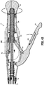
- Safety bar 390 is rotatable between a safe position ( FIGS. 40 and 41 ), wherein the second end of safety bar 390 abuts stationary handle 22 to inhibit actuation of firing trigger 24, and a ready position ( FIG. 43 ), wherein safety bar 390 is positioned within a recess 24a defined in firing trigger 24 to permit actuation of firing trigger 24.
- Other suitable trigger locks are described in U.S. Patent 7,303,106 to Milliman et al. , and U.S. Patent No. 7,857,187 to Milliman and U.S. Patent No. 6,945,444 to Gresham et al. .
- firing trigger 24 may be actuated by pivoting firing trigger 24 about pivot members 312, 352 towards stationary handle 22 in a counter-clockwise direction (from the position shown in FIG. 43 ).
- firing link 310 is pivoted about pivot member 312 in a clockwise direction (from the position shown in FIG. 43 ) towards stationary handle 22 to urge firing trigger 24 and coupling member 350 distally relative to stationary handle 22.
- Distal translation of coupling member 350 urges pusher link assembly 330 distally against the bias of spring 356.
- Firing assembly 300 may further include a feedback mechanism similar to that disclosed in U.S. Patent No. 7,857,187 to Milliman .
- anvil assembly 400 includes an anvil head assembly 410 and an anvil center rod assembly 420.
- Anvil head assembly 410 includes a post 412 and an anvil head 414 that defines a plurality of pockets 419 for receiving and forming staples 600 about tissue.
- Anvil center rod assembly 420 includes an anvil center rod 422 that is pivotably engaged to post 412 of anvil head assembly 410 via a pivot member 424 to permit anvil head assembly 410 to pivot relative to anvil center rod assembly 420.
- Anvil center rod 422 defines a hollow interior that is configured to receive anvil retainer 260.
- annular recess 426 which extends inwardly into the hollow interior of anvil center rod 422, receives annular protrusion 268 of anvil retainer 260 such that anvil center rod 422 and, thus, anvil assembly 400 is secured about anvil retainer 260.
- Anvil assembly 400 may further be configured to include any or all of the features of the anvil assembly described in U.S. Patent No. 7,857,187 to Milliman or U.S. Patent No. 6,945,444 to Gresham et al. .
- stapling assembly 100 includes a cartridge assembly 110 and an engagement assembly 140.
- Cartridge assembly 110 is configured to house a plurality of surgical staples 600 therein and, upon actuation of firing assembly 300, to facilitate the ejection of surgical staples 600 therefrom, through tissue, and into anvil head 414 ( FIGS. 47 and 49 ) for formation of the surgical staples 600 about tissue.
- Engagement assembly 140 is configured to facilitate operable engagement of stapling assembly 100 to engagement shell 36 at the distal end of outer tube 32 of elongated central body portion 30.
- Stapling assembly 100 (or component(s) thereof) may be formed as a disposable assembly that is configured to be replaced with a new stapling assembly after each firing.
- engagement assembly 140 includes a distal shell 142 and an inner extension 143, each of which may be formed from any suitable material, e.g., polyethylene, and is configured as a disposable component.
- Distal shell 142 includes an outer housing portion 144 and an inner guide portion 146.
- Inner extension 143 ( FIG. 14 ) is releasably threadingly engagable with inner guide portion 146 of distal shell 142 and is configured to extend proximally therefrom and into distal segment 336 of pusher link assembly 330 to facilitate alignment of cartridge assembly 110 and distal segment 336 of pusher link assembly 330 with one another.
- Outer housing portion 144 has a distal cylindrical section 147, a central conical section 148, and a proximal cylindrical section 149 that defines a smaller diameter than distal cylindrical section 147.
- a plurality of openings 150 are formed in conical section 148 to permit fluid and tissue passage during operation of surgical stapling apparatus 10.
- a pair of diametrically opposed engagement tabs 151, each including an engagement nub 152, is formed on the exterior surface of proximal cylindrical section 149.
- Engagement tabs 151 are positioned to be received in engagement slots 165 defined within engagement shell 36 of central elongated body portion 30 to facilitate releasable securement of stapling assembly 100 at the distal end of outer tube 32 of elongated body portion 30.
- Distal shell 142 further includes a plurality of spaced-apart orientation bars 154 ( FIG. 23 ) disposed about the interior surface of proximal cylindrical section 149.
- Orientation bars 154 are configured for receipt within slots 33 ( FIG. 22 ) defined about the distal end of outer tube 32 to rotationally fix distal shell 142 about the distal end of outer tube 32 of elongated body portion 30 during assembly.
- orientation bars 154 FIG. 23
- other suitable mechanisms for maintaining alignment are also contemplated, e.g., tabs and protrusions, ribs and recesses, etc.
- engagement shell 36 of central elongated body portion 30 includes a distal cylindrical section 161, a central conical section 162, and a proximal cylindrical section 163 that defines a smaller diameter than distal cylindrical section 161.
- Engagement shell 36, outer tube 32, and/or proximal bushing 34 of central elongated body portion 30 may be formed from a sterilizable material, e.g., stainless steel or other suitable sterilizable material (metals, plastics, etc.), such that these components may be sterilized and reused without the material substantially degrading.
- a plurality of openings 164 are formed in conical section 162 to permit fluid and tissue passage during operation of surgical stapling apparatus 10.
- Proximal cylindrical section 163 of engagement shell 36 is rotatably supported about the distal end of outer tube 32 of elongated body portion 30 in any suitable fashion, e.g., via engagement between first and second C-clips 39a, 39b which are supported on the distal end of outer tube 32.
- engagement shell 36 With engagement shell 36 disposed about outer tube 32 between C-clips 39a, 39b, a relatively small amount of longitudinal translation of engagement shell 36 relative to outer tube 32 is permitted such that engagement shell 36 is permitted to move or slide about outer tube 32 between first C-clip 39a and second C-clip 39b as will be discussed in further detail below.
- distal cylindrical section 161 of engagement shell 36 is configured to receive proximal cylindrical section 149 of distal shell 142. More specifically, distal cylindrical section 161 of engagement shell 36 includes a pair of opposed engagement slots 165 configured to receive engagement tabs 151 of distal shell 142. Engagement slots 165 each define an open end configured to permit passage of engagement tabs 151 therethrough upon insertion of proximal cylindrical section 149 of distal shell 142 into distal cylindrical section 161 of engagement shell 36. Engagement slots 165 also include a transverse portion configured to permit lateral translation of a respective engagement tab 151 upon relative rotation between distal shell 142 and engagement shell 36. Slots 165 each further include an engagement notch 166 ( FIG.
- a biasing member 170 is positioned about outer tube 32 between outer tube 32 and engagement shell 36 and, more particularly, between second C-clip 39b and proximal cylindrical section 163 of engagement shell 36. Biasing member 170 is configured to bias engagement shell 36 proximally about outer tube 32.
- cartridge assembly 110 is housed within distal shell 142 of engagement assembly 140 and includes a pusher 112, a cylindrical knife 114, and a staple guide cap 116.
- cartridge assembly 110 and distal shell 142 are configured as disposable components.
- Pusher 112 of cartridge assembly 110 includes a central bore 118 and is configured to be received within distal shell 142.
- pusher 112 includes a distal cylindrical section 119, which is slidably positioned within distal cylindrical section 147 of distal shell 142, a central conical section 121, which is slidably positioned within central conical section 148 of distal shell 142, and a proximal cylindrical section 123 having a smaller diameter than distal cylindrical section 119, which is slidably positioned within proximal cylindrical section 149 of distal shell 142.
- the proximal end of pusher 112 includes a pair of proximally-extending arm members 125. Arm members 125 each include a finger 127 that is configured for insertion into and locking engagement within annular recess 339 of collar 338 of distal segment 336 of pusher link assembly 330.
- the distal end of pusher 112 includes a plurality of distally-extending pusher fingers 129 dimensioned to be slidably received within slots 131 formed in staple guide cap 116.
- Staple guide cap 116 is supported within and engaged about the distal end of distal shell 142 via the positioning of tabs 133 within recesses 135, e.g., via snap-fit, welding, adhesion, etc.
- Each slot 131 formed within staple guide cap 116 is configured to retain a surgical staple 600 such that, upon advancement of pusher 112 within distal shell 142 via actuation of firing trigger 24, surgical staples 600 are ejected from slots 131 of staple guide cap 116, through tissue, and into anvil head 414 ( FIGS. 47 and 49 ) of anvil assembly 400 ( FIGS. 47 and 49 ) for formation about tissue.
- cylindrical knife 114 is pinned within bore 118 of pusher 112 to fixedly secure knife 114 in relation to pusher fingers 129 such that advancement of pusher 112 to eject surgical staples 600 from staple guide 116 is effected simultaneously with advancement of knife 114 through tissue.
- the distal end of knife 114 includes a circular cutting edge 115 to facilitate the cutting of tissue.
- stationary handle 22 is formed from first and second handle sections 22a, 22b and support chassis 22c that cooperate to house and support the internal components of handle portion 20.
- Handle sections 22a, 22b and support chassis 22c are configured as reusable, sterilizable components, although handle sections 22a, 22b and/or chassis 22c may alternatively be configured as disposable components.
- Support chassis 22c includes a central body portion 25 having first and second lateral flanges 25a, 25b that are configured for receipt and pivotable engagement within first and second recesses 22a', 22b' of handle sections 22a, 22b, respectively.
- Engagement pins 25c are provided at the proximal and distal ends of lateral flanges 25a, 25b and are configured for pivotable engagement within corresponding apertures defined within handle sections 22a, 22b adjacent recesses 22a', 22b'.
- Pins 25c pivotably secure handle sections 22a and 22b to flanges 25a, 25b of support chassis 22c within recesses 22a', 22b'.
- Pins 25c may be configured for snap-fit engagement within the apertures of handle sections 22a, 22b, although other pivotable securement mechanisms are also contemplated.
- Central body portion 25 of support chassis 22c further includes an indicator window 25d through which visual indicators 278a, 278b may be viewed, and proximal and distal support rings 23a, 23b, respectively, for supporting collar 232 and screw 220, respectively, of approximation assembly 200.
- Indicator window 25b may be formed via a hole or aperture extending through central body portion 25 of support chassis 22c or may be formed from a transparent section of central body portion 25.
- Handle sections 22a, 22b further include threaded distal extensions 22f, 22g that cooperate to define a generally annular threaded member for releasably engaging proximal bushing 34 of central body portion 30. Engagement between distal extensions 22f, 22g and proximal bushing 34 releasably secures outer tube 32 and handle portion 20 to one another and also secures handle sections 22a, 22b to one another at the distal ends thereof.
- a pin (not shown) extending from handle section 22a is configured for frictional receipt within an aperture 22d of handle section 22b to releasably secure handle sections 22a, 22b to one another at the proximal ends thereof.
- handle sections 22a, 22b retains support chassis 22c in a fixed position relative to handle sections 22a, 22b, e.g., with handle sections 22a, 22b secured to one another, support chassis 22c is no longer permitted to pivot relative to handle sections 22a, 22b
- distal head portion 40 ( FIG. 1 ) of surgical stapling apparatus 10 ( FIG. 38 ) inserted into an internal surgical site, before after engagement of anvil assembly 400.
- anvil assembly 400 and stapling assembly 100 are positioned adjacent tissue to be stapled.
- safety bar 390 is disposed in the safety position such that actuation of firing trigger 24 is inhibited.
- anvil assembly 400 may be approximated relative to stapling assembly 100 to clamp tissue therebetween via manipulating approximation assembly 200. More specifically, anvil assembly 400 is moved to the approximated or closed position to grasp tissue between anvil assembly 400 and stapling assembly 100 by rotating rotation knob 26 in a first direction ( FIG. 43 ). Rotation of knob 26 in the first direction causes cylindrical sleeve 230 to rotate to move pin 224 along helical channel 222 of screw 220 such that screw 220 is translated proximally ( FIG. 44 ).
- screw 220 is connected to screw extensions 240 and 250 which, in turn, are fastened at their distal ends to anvil retainer 260, such that anvil retainer 260 is likewise translated proximally to approximate anvil assembly 400 relative to stapling assembly 100.
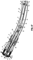
- Knob 26 may be rotated to approximate anvil assembly 400 relative to stapling assembly 100 to clamp tissue therebetween until the minimum tissue gap between anvil assembly 400 and stapling assembly 100 ( FIG. 47 ), which is set via screw stop 270, is achieved.
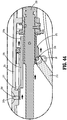
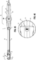
- screw stop 270 which is supported on screw 220, is moved proximally. Movement of the anvil assembly 400 to the approximated position can be confirmed once visual indicator 278b is viewable through indicator window 25d of central body portion 25 of support chassis 22c (see FIGS. 44-46 ).
- firing assembly 300 may be actuated to staple and core the clamped tissue.
- safety bar 390 is rotated from the safety position ( FIGS. 40 and 41 ) to the ready position ( FIG. 43 ). With safety bar 390 no longer inhibiting actuation of firing trigger 24, firing assembly 400 may be actuated.
- trigger 24 is compressed towards stationary handle 22, as shown in FIG. 48 .
- firing trigger 24 is connected through coupling member 350 to the proximal end of pusher link assembly 330. Accordingly, as firing trigger 24 is actuated, pusher link assembly 330 is moved distally to urge pusher 112 of cartridge assembly 110 distally. Upon distal translation of pusher 112 relative to staple guide cap 116, fingers 129 of pusher 112 engage and eject staples 600 from staple guide cap 116, through tissue, and into anvil head 414 of anvil assembly 400, which form staples 600 about tissue ( FIG. 49 ). Cylindrical knife 114 is moved concurrently with pusher 112 such that knife 114 is likewise advanced distally to core tissue.
- surgical stapling apparatus 10 is used to perform a circular anastomosis.
- circular anastomoses are required during procedures for removing a portion of a diseased vessel such as the colon or the intestine. During such a procedure, the diseased portion of the vessel is removed and the end portions of the remaining first and second vessel sections are joined together using the surgical stapling apparatus 10.
- the anvil assembly 400 with a removable trocar (not shown) attached thereto is positioned in the first vessel section on a first side of the diseased portion.
- a removable trocar which is suitable for use with the anvil assembly 400 is disclosed in U.S. Patent No. 6,945,444 to Gresham et al. , which, as discussed above, is cited herein.
- the removable trocar is pushed through the suture line in the end of the first vessel section and removed from the anvil assembly.
- trocar tip 267 of anvil retainer 260 is pushed through the suture line in the second vessel section and is joined to the center rod of the anvil assembly 400.
- the surgical stapling apparatus 10 can now be approximated and fired in the manner discussed above to join the ends of the first and second vessel sections and core out any tissue obstructing the vessel lumen.
- surgical stapling apparatus 10 may be removed from the internal surgical site. More specifically, anvil assembly 400 may be configured to pivot to a low-profile configuration after firing and upon un-approximation of anvil assembly 400 relative to stapling assembly 100 to facilitate removal of surgical stapling apparatus 10 from the internal surgical site.
- a suitable tilting mechanism is described in U.S. Patent No. 7,857,187 to Milliman or U.S. Patent No. 6,945,444 to Gresham et al. .
- anvil assembly 400 need not have a pivotal head and may be removed from the surgical site in the same orientation as it was advanced into the surgical site.
- surgical stapling apparatus 10 may be disassembled to facilitate sterilization of the reusable components and replacement of the disposable components. More specifically, and with reference to FIGS. 13-37 , to disassemble surgical stapling apparatus 10, anvil assembly 400 ( FIGS. 1 , 47 , and 49 ) is first removed from anvil retainer 260.
- anvil assembly 400 In order to disengage anvil assembly 400 from anvil retainer 260, anvil assembly 400 is moved to an unapproximated position spaced-apart from stapling assembly 100 by rotating knob 26 in a second, opposite direction, sufficiently such that annular protrusion 268 of anvil retainer 260 and annular recess 426 of anvil center rod 422 are no longer positioned within inner guide portion 146 of stapling assembly 100.
- anvil assembly 400 may be separated from anvil retainer 260 by applying sufficient force to the anvil assembly 400 so as to flex center rod 422 radially outwardly to disengage annular protrusion 268 from annular recess 426, thus allowing anvil assembly 400 to be removed from anvil retainer 260.
- Anvil assembly 400 is configured as a sterilizable, reusable component although it is also contemplated that anvil assembly be configured as a reusable component.
- stapling assembly 100 may be disengaged from surgical stapling apparatus 10. More specifically, stapling assembly 100 is disengaged from the distal end of outer tube 32 by first urging engagement shell 36 distally against the bias of biasing member 170 and relative to proximal shell 142 such that engagement nubs 152 of distal shell 142 are disengaged from engagement notches 166 of engagement shell 36. Thereafter, engagement shell 36 is rotated relative to distal shell 142 such that engagement tabs 151 are translated along the transverse portions of engagement slots 165 to the open ends thereof.
- proximal section 149 of distal shell 142 is squeezed inwardly and translated distally to disengage fingers 127 of arms 125 of cartridge assembly 110 from engagement within annular recess 339 of collar 338 of distal segment 336 of pusher link assembly 330. Thereafter, engagement shell 36 is allowed to return proximally under the bias of biasing member 170 such that engagement tabs 151 are released from engagement slots 165, thereby disengaging distal shell 142 from engagement shell 36.
- stapling assembly 100 may then be removed from positioning about anvil retainer 260 and may be disposed of, although it is also contemplated that one or more components of stapling assembly 100 be sterilizable for reuse.
- proximal bushing 34 is disengaged from the distal ends of handle sections 22a, 22b by rotating proximal bushing 34 relative to handle portion 22.
- the lower ends of handle sections 22a, 22b are pivoted away from one another and relative to support chassis 22c to open handle portion 22, thus exposing approximation assembly 200 and firing assembly 300.
- approximation assembly 200 and firing assembly 300 may be removed from support chassis 22c and handle portion 22.
- sterilization of each of these components for reuse may be readily achieved.
- one or more of theses components may be configured as a disposable component and, thus, may be replaced with a new component rather than being sterilized.
- surgical stapling apparatus 10 may be reassembled for subsequent use. Initially, the distal end of approximation assembly 200 is inserted through coupling member 350 and pusher link assembly 330 of firing assembly 300.
- approximation assembly 200 is mounted within support rings 23a, 23b, of support chassis 22c such that a wing 274 of screw stop 270 is slidably received within channel 27 of handle section 22b, a wing 358 of coupling member 350 is slidably received within channel 29 of handle section 22b (see FIGS. 8-9 ), and pivot member 316 is received within vertical slot 28 of handle section 22b.
- handle sections 22a, 22b may be closed, or pivoted towards one another and relative to support chassis 22c to house the proximal components of firing assembly 300 and approximation assembly 200 therein.
- elongated central body portion 30 may be maneuvered into position such that outer tube 32 is disposed about pusher link assembly 330 of firing assembly 300, which is disposed about screw extensions 240, 250 of approximation assembly 200, with anvil retainer 260 extending distally from both pusher link 330 and outer tube 32.
- the proximal end of outer tube 32 may be secured relative to stationary handle 22 via threadingly engaging proximal bushing 34 about distal extensions 22f, 22g of handle sections 22a, 22b, respectively.
- cartridge assembly 110 which is engaged within distal shell 142, is approximated relative to the engagement shell 36 disposed at the distal end of outer tube 32. More specifically, distal shell 142, including cartridge assembly 110, is positioned about anvil retainer 260 and is approximated relative to the distal end of outer tube 32 such that orientation bars 154 of distal shell 142 are received within slots 33 defined at the distal end of outer tube 32 to ensure proper alignment therebetween.
- engagement shell 36 With cartridge assembly 110 engaged at the distal end of pusher link assembly 330, engagement shell 36 is moved distally against the bias of biasing member 170 such that engagement tabs 151 of distal shell 142 are inserted through the open ends of engagement slots 165 of engagement shell 36. Once engagement tabs 151 of distal shell 142 are inserted into engagement slots 165 of engagement shell 36, engagement shell 36 is rotated relative to distal shell 142 such that engagement tabs 151 are translated along the transverse portions of engagement slots 165 and away from the open ends thereof. Once sufficiently rotated to the position shown in FIG.
- engagement shell 36 may be released, allowing biasing member 170 to bias engagement shell 36 proximally and away from distal shell 142 such that engagement nubs 152 are received within engagement notches 166 to secure distal shell 142 and engagement shell 36 to one another about the distal end of outer tube 32.
- anvil assembly 400 may be engaged to anvil retainer 260, which extends distally through and from stapling assembly 100.
- anvil center rod 422 is disposed about anvil retainer 260 until annular recess 426 receives annular protrusion 268 of anvil retainer 260 to secure anvil assembly 400 about anvil retainer 260.
- annular protrusion 268 is positioned within stapling assembly 100, thus inhibiting removal of anvil assembly 400 therefrom due to the inability of annular recess 426 of anvil center rod 422 to flex outwardly to disengage from annular protrusion 268. Rather, removal of anvil assembly 422 is only permitted when anvil retainer 260 is disposed in an extended position, e.g., the position shown in FIG. 1 .
- the above-described cycle of use, disassembly, sterilization and replacement, and reassembly may be repeated for a plurality of usage cycles.
Landscapes
- Health & Medical Sciences (AREA)
- Life Sciences & Earth Sciences (AREA)
- Surgery (AREA)
- Heart & Thoracic Surgery (AREA)
- Engineering & Computer Science (AREA)
- Biomedical Technology (AREA)
- Nuclear Medicine, Radiotherapy & Molecular Imaging (AREA)
- Medical Informatics (AREA)
- Molecular Biology (AREA)
- Animal Behavior & Ethology (AREA)
- General Health & Medical Sciences (AREA)
- Public Health (AREA)
- Veterinary Medicine (AREA)
- Physiology (AREA)
- Surgical Instruments (AREA)
Description
- The present disclosure relates generally to a surgical stapling apparatus for applying surgical staples to body tissue and, more particularly, to a surgical stapling apparatus for performing circular anastomosis of hollow tissue structures which includes reusable components.
- Anastomosis refers to the surgical joining of separate hollow tissue sections. Typically, an anastomosis procedure follows surgery in which a diseased or defective section of a hollow tissue structure is removed, thus requiring the joining of the remaining end sections of the tissue structure. Depending on the particular procedure being performed and/or other factors, the end sections of the tissue may be joined by circular anastomosis, e.g., end-to-end anastomosis, end-to-side anastomosis, or side-to-side anastomosis.
- In a circular anastomosis procedure, two end sections of a tubular organ are joined using a stapling apparatus that drives a circular array of staples through each of the end sections to join the end sections to one another in end-to-end relation and simultaneously cores any tissue within the newly joined hollow tissue structure to clear the passage defined by the hollow tissue structure. A typical circular anastomosis apparatus includes an elongated shaft having a handle portion at a proximal end and a staple holding component at a distal end. An anvil assembly including an anvil rod and an attached anvil head is mounted to the distal end of the elongated shaft adjacent the staple holding component. In use, the end portions to be joined are clamped between the anvil head and the staple holding component. The clamped end portions are then joined to one another by driving one or more staples from the staple holding component, through the tissue, and into the anvil head to form the staples about the tissue. An example of such a circular anastomosis apparatus is described in
U.S. Patent No. 7,857,187 to Milliman . -
US 4 304 236 discloses an apparatus for circular surgical stapling of hollow organs comprising an instrument and disposable cartridge assembly. The instrument comprises a housing with a throughbore in which a tube that is received for reciprocation by means of a manually operable squeeze handle. A rod reciprocates within the tube by means of a wing nut cooperating with a threaded part of the rod. A two-part disposable cartridge assembly comprised of an anvil-carrying part and a staple-carrying part are detachably mounted on the rod and housing, respectively. Keys are provided to hold the anvil-carrying part and the staple-carrying part in rotational orientation relative to the rod. - Typically, surgical stapling apparatus for performing circular anastomosis procedures are disposable after a single use. Because of the high costs associated with the use of disposable surgical stapling apparatus, a need exists for a surgical stapling apparatus that includes reusable components and is configured to facilitate effective sterilization of the reusable components.
- The invention is defined in the appended claims. A surgical stapling apparatus provided in accordance with the present disclosure includes a handle portion, an elongated body portion, a firing assembly, and a stapling assembly. The elongated body portion extends distally from the handle portion. The elongated body portion includes an engagement member rotatably supported on a distal portion of the elongated body portion. The engagement member defines an engagement slot and is axially movable about the elongated body portion from a retracted position to an advanced position. The firing assembly includes a firing trigger, a firing link, and a pusher link. The pusher link extends through the elongated body portion and is configured for distal translation through the elongated body portion in response to actuation of the firing trigger. The stapling assembly is configured to house a plurality of surgical staples. The stapling assembly includes an outer shell having an engagement tab. The engagement member is rotatable relative to the elongated body portion and the stapling assembly to releasably engage the engagement tab within the engagement slot to releasably secure the stapling assembly at the distal end of the elongated body portion such that, in response to distal advancement of the firing pusher, the plurality of surgical staples are ejected from the stapling assembly.
- In embodiments, the surgical stapling apparatus further includes an approximation assembly. The approximation assembly includes a drive member configured to extend distally from the elongated body potion and the stapling assembly. The distal end of the drive member is configured to releasably engage an anvil assembly.
- In embodiments, the surgical stapling apparatus further includes an approximation knob extending from the handle portion. The approximation knob is coupled to the drive member and is selectively actuatable to move the anvil assembly between a spaced-apart position and an approximated position relative to the stapling assembly.
- In embodiments, the drive member defines a helical channel and the approximation knob is coupled to a pin disposed within the helical channel such that rotation of the approximation knob effects translation of the drive member.
- In embodiments, the handle portion includes an indicator window configured to permit visualization into the handle portion to confirm a position of the anvil assembly relative to the stapling assembly.
- In embodiments, a biasing member is disposed about the elongated body portion and configured to bias the engagement member towards the retracted position. As such, the engagement tab is retained in engagement within the engagement slot under the bias of the biasing member.
- In embodiments, the engagement tab further includes an engagement nub and the engagement slot further includes an engagement notch. The engagement nub is configured to engage the engagement notch to secure the stapling assembly at the distal end of the elongated body portion.
- In embodiments, the stapling assembly includes a cartridge assembly disposed within the outer shell. The cartridge assembly may include a pusher including a plurality of pusher fingers configured to support the plurality of surgical staples and a staple guide member configured to guide ejection of the surgical staples from the stapling assembly.
- In embodiments, the handle portion is formed from first and second handle sections movable relative to one another between a closed configuration and an open configuration. The handle portion may further include a chassis interconnecting the first and second handle sections. The chassis may also be configured to support a portion of the approximation assembly and/or a portion of the firing assembly.
- In embodiments, the elongated body portion defines a curved configuration and the pusher link includes a plurality of link segments pivotably coupled to one another to facilitate translation of the pusher link through the curved elongated body portion. The link segments may be pivotably coupled to one another via a ball-and-socket joint(s).
- Also provided in accordance with the present disclosure is a method of surgery. The method includes providing a surgical stapling apparatus including a handle portion formed from first and second handle sections, an elongated body portion extending distally from the handle portion and having an engagement member coupled to a distal portion of the elongated body portion, a firing assembly, an approximation assembly, an anvil assembly disposed at a distal end of the approximation assembly, and a first stapling assembly housing a first plurality of surgical staples. The first stapling assembly is engaged to the engagement member of the elongated body portion. The surgical stapling apparatus may otherwise be configured similar to any of the embodiments described herein. The method further includes inserting the surgical stapling apparatus into an internal surgical site, actuating the approximation assembly to clamp tissue between the first stapling assembly and the anvil assembly, actuating the firing assembly to eject the first plurality of surgical staples from the first stapling assembly, through the clamped tissue, and into the anvil assembly to form the first plurality of surgical staples about the clamped tissue, removing the surgical stapling apparatus from the internal surgical site, and disengaging the first stapling assembly from the engagement member.
- In embodiments, the method further includes moving the first and second handle sections relative to one another from a closed position to an open position, disengaging the handle portion, the elongated body portion, the anvil assembly, the firing assembly, and the approximation assembly from one another, sterilizing the handle portion, the elongated body portion, the anvil assembly, the firing assembly, and the approximation assembly, reengaging the handle portion, the elongated body portion, the anvil assembly, the firing assembly, and the approximation assembly to one another, moving the first and second handle sections relative to one another from the open position back to the closed position, and engaging a second stapling assembly with the engagement member. The second stapling assembly houses a second plurality of surgical staples.
- In embodiments, the method further includes inserting the surgical stapling apparatus into an internal surgical site, actuating the approximation assembly to clamp tissue between the second stapling assembly and the anvil assembly, and actuating the firing assembly to eject the second plurality of surgical staples from the second stapling assembly, through the clamped tissue, and into the anvil assembly to form the second plurality of surgical staples about the clamped tissue. See also, for example,
U.S. Patent No. 7,857,187 to Milliman , previously cited herein,U.S. Patent No. 6,945,444 to Gresham et al. , the entire contents of which can be found therein, andU.S. Patent 7,303,106 to Milliman et al. . - Various embodiments of the presently disclosed surgical stapling apparatus are described herein with reference to the drawings wherein:
-
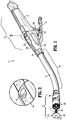
FIG. 1 is a top, side, perspective view from the distal end of one embodiment of the presently disclosed surgical stapling apparatus; -
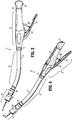
FIG. 2 is an enlarged view of the area of detail indicated as "2" inFIG. 1 ; -
FIG. 3 is a side view of the surgical stapling apparatus shown inFIG. 1 with the anvil assembly removed; -
FIG. 4 is a top, side, perspective view from the proximal end of the surgical stapling apparatus shown inFIG. 1 with the anvil assembly removed; -
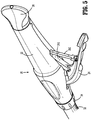
FIG. 5 is a bottom, side, perspective view of the handle portion of the surgical stapling apparatus shown inFIG. 1 ; -
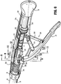
FIG. 6 is a side, perspective view of the handle portion of the surgical stapling apparatus shown inFIG. 1 with one of the handle sections removed to show the internal components of the handle portion; -
FIG. 7 is a side, perspective view of the proximal end of the handle portion of the surgical stapling apparatus ofFIG. 1 with the handle sections removed and the proximal portions of the firing assembly and approximation assembly illustrated; -
FIG. 8 is a transverse, cross-sectional view taken along section line 8-8 ofFIG. 6 ; -
FIG. 9 is a transverse, cross-sectional view taken along section line 9-9 ofFIG. 6 ; -
FIG. 10 is a transverse, cross-sectional view taken along section line 10-10 ofFIG. 6 ; -
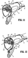
FIG. 11 is a transverse, cross-sectional view taken along section line 11-11 ofFIG. 6 ; -
FIG. 12 is a transverse, cross-sectional view taken along section line 12-12 ofFIG. 6 ; -
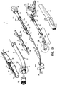
FIG. 13 is an exploded, perspective view of the surgical stapling apparatus shown inFIG. 1 ; -
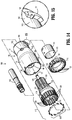
FIG. 14 is an exploded, perspective view of the replaceable stapling assembly of the surgical stapling apparatus shown inFIG. 1 ; -
FIG. 15 is an enlarged view of the area of detail indicated as "15" inFIG. 14 ; -
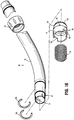
FIG. 16 is an exploded, perspective view of the tube assembly of the surgical stapling apparatus shown inFIG. 1 ; -
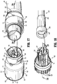
FIG. 17 is an enlarged view of the area of detail indicated as "17" inFIG. 13 spaced from the replaceable stapling assembly of the surgical stapling apparatus shown inFIG. 13 ; -
FIG. 18 is an enlarged view of the area of detail indicated as "18" inFIG. 13 spaced from the pusher of the surgical stapling apparatus shown inFIG. 13 ; -
FIG. 19 is a longitudinal, cross-sectional view taken along section line 19-19 ofFIG. 18 ; -
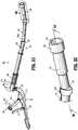
FIG. 20 is a longitudinal, cross-sectional view of the replaceable stapling assembly and the distal end of the firing assembly shown disengaged from one another; -
FIG. 21 is a longitudinal, cross-sectional view of the replaceable stapling assembly and the distal end of the firing assembly shown engaged to one another; -
FIG. 22 is a side view of the replaceable stapling assembly and the outer tube assembly shown disengaged from one another; -
FIG. 23 is a side, perspective view from a proximal end of the replaceable stapling assembly of the surgical stapling apparatus shown inFIG. 1 ; -
FIG. 24 is a longitudinal, cross-section view taken along section line 24-24 ofFIG. 17 ; -
FIG. 25 is a side view of the replaceable stapling assembly during initiation of engagement between the replaceable stapling assembly and the outer tube assembly of the surgical stapling apparatus shown inFIG. 1 ; -
FIG. 26 is a side view of the replaceable stapling assembly during engagement between the replaceable stapling assembly and the outer tube assembly of the surgical stapling apparatus shown inFIG. 1 ; -
FIG. 27 is a side view of the replaceable stapling assembly shown engaged to the outer tube assembly of the surgical stapling apparatus shown inFIG. 1 ; -
FIG. 28 is a top, side, perspective view of the approximation assembly of the surgical stapling apparatus shown inFIG. 1 ; -
FIG. 29 is an enlarged view of the area of detail indicated at "29" inFIG. 28 ; -
FIG. 30 is an exploded, side, perspective view of the approximation assembly of the surgical stapling apparatus shown inFIG. 1 ; -
FIG. 31 is a side, perspective view of the firing assembly of the surgical stapling apparatus shown inFIG. 1 ; -
FIG. 32 is an enlarged view of the area of detail indicated as "32" inFIG. 31 ; -
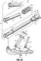
FIG. 33 is an exploded, perspective view of the firing assembly of the surgical stapling apparatus shown inFIG. 13 ; -
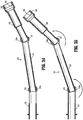
FIG. 34 is a longitudinal, cross-sectional view of the pusher link assembly shown inFIG 31 ; -
FIG. 35 is a longitudinal, cross-sectional view of the pusher link assembly shown inFIG. 34 with the inner tube in a further articulated position; -
FIG. 36 is a top, side, perspective view from a distal end of the stationary handle of the handle assembly of the surgical stapling apparatus shown inFIG. 1 ; -
FIG. 37 is an exploded, side, perspective view of the stationary handle of the surgical stapling apparatus shown inFIG. 36 ; -
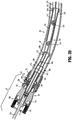
FIG. 38 is a longitudinal, cross-sectional view of the surgical stapling apparatus shown inFIG. 1 with the anvil assembly removed; -
FIG. 39 is an enlarged view of the area of detail indicated as "39" inFIG. 38 ; -
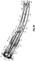
FIG. 40 is an enlarged view of the area of detail indicated as "40" inFIG. 38 ; -
FIG. 41 is an enlarged, cross-sectional view of the area of detail indicated as "41" inFIG. 40 ; -
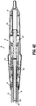
FIG. 42 is a longitudinal, cross-sectional view taken along section line 42-42 ofFIG. 40 ; -
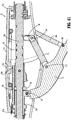
FIG. 43 is a longitudinal, cross-sectional view of the handle portion of the surgical stapling apparatus ofFIG. 1 shown in a position corresponding to the approximated position of the surgical stapling apparatus; -
FIG. 44 is an enlarged, cross-sectional view of the area of detail indicated as "44" inFIG. 43 ; -
FIG. 45 is a top view of the surgical stapling apparatus ofFIG. 1 in the approximated position; -
FIG. 46 is an enlarged view of the area of detail indicated as "46" inFIG. 45 ; -
FIG. 47 is a longitudinal, cross-sectional view of the distal end of the surgical stapling apparatus ofFIG. 1 shown in the approximated position clamping tissue; -
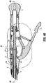
FIG. 48 is a longitudinal, cross-sectional view of the handle portion of the surgical stapling apparatus ofFIG. 1 shown in a position corresponding to the fired position of the surgical stapling apparatus; and -
FIG. 49 is a longitudinal, cross-sectional view of the distal end of the surgical stapling apparatus ofFIG. 1 shown after firing and formation of the staples about the clamped tissue. - Embodiments of the presently disclosed surgical stapling apparatus will now be described in detail with reference to the drawings in which like reference numerals designate identical or corresponding elements in each of the several views. Throughout this description, the term "proximal" will refer to the portion of the apparatus closest to the user and the term "distal" will refer to the portion of the apparatus farthest from the user.
- With general reference to
FIGS. 1-49 , an embodiment of the presently disclosed surgical stapling apparatus is shown identified byreference numeral 10.Surgical stapling apparatus 10 includes aproximal handle portion 20, an elongatedcentral body portion 30, and adistal head portion 40. With particular reference toFIGS. 1-3 and5-7 ,proximal handle portion 20 includes astationary handle 22, a firingtrigger 24, and arotatable approximation knob 26.Stationary handle 22 is formed from first and second releasably engagablehandle sections support chassis 22c (seeFIGS. 36-37 ) that cooperate to house and support the internal components ofhandle portion 20, e.g., the proximal components ofapproximation assembly 200 and firingassembly 300.Proximal handle portion 20 and the internal components thereof will be described in greater detail below. - With particular reference to
FIGS. 1 and13-16 , elongatedcentral body portion 30 ofsurgical stapling apparatus 10 includes a curved elongatedouter tube 32, aproximal bushing 34, and adistal engagement shell 36.Outer tube 32 is configured to receive components ofapproximation assembly 200 and firingassembly 300. As will be discussed in further detail below,proximal bushing 34 is provided to facilitate releasable threaded engagement of the proximal end ofouter tube 32 withstationary handle 22 ofhandle portion 20. In addition,engagement shell 36 is provided to facilitate releasable engagement ofreplaceable stapling assembly 100 with the distal end ofouter tube 32. -
Distal head portion 40 ofsurgical stapling apparatus 10 includes an anvil assembly 400 (FIG. 1 ) that is releasably engagable with the distal end of approximation assembly 200 (FIG. 28 ), and areplaceable stapling assembly 100 that is releasably engagable with the distal end of elongatedcentral body portion 30. Replaceable stapling assembly 100 (or portions thereof) is configured as a disposable component that is to be replaced with a new replaceable stapling assembly 100 (or portions thereof) after each firing. The remaining components ofsurgical stapling apparatus 10 are configured as reusable, sterilizable components, although one or more of these components may alternatively be configured as a disposable component.Distal head portion 40 will be described in greater detail below. - The various components of
surgical stapling apparatus 10 described hereinbelow are configured to facilitate the assembly and disassembly ofsurgical stapling apparatus 10, thus facilitating the disposal and replacement of those components that are disposable and the sterilization and reassembly of those components that are reusable. The materials used to form the various components ofsurgical stapling apparatus 10 will depend upon the strength requirements of the particular component and the use requirements of the particular component, e.g., whether the component is reusable or disposable. The reusable components, for example, may generally be formed from thermoplastics including polycarbonates, and metals including stainless steel and aluminum, that are suited to withstand repeated sterilization procedures, e.g., autoclaving. - Referring to
FIGS. 1 ,6 ,7 ,13 , and28-30 ,approximation mechanism 200 ofsurgical stapling apparatus 10 includes anapproximation knob 26, adrive screw 220, arotatable sleeve 230, first andsecond screw extensions anvil retainer 260.Rotatable sleeve 230 includes a substantially cylindricalhollow body portion 231 and a substantiallycylindrical collar 232 that together define a central bore 233 (FIG. 30 ).Body portion 231 is supported withinproximal handle portion 20 viaproximal support ring 23a (FIG. 13 ) ofsupport chassis 22c, as will be described in greater detail below. The proximal end ofbody portion 231 ofrotatable sleeve 230 extends through anopening 22e in the proximal end ofstationary handle 22. A pair of diametricallyopposed ribs 235 are positioned or formed on the outer surface ofbody portion 231.Approximation knob 26 includes a pair of internal slots (not shown) positioned to receiveribs 235 ofsleeve 230 torotatably fix sleeve 230 toknob 26 such that rotation ofknob 26 effects similar rotation ofsleeve 230. Greater orfewer ribs 235 and slots 212 may alternatively provided. Further, this configuration may be reversed, e.g., whereribs 235 are disposed onapproximation knob 26 and slots 212 are defined withinsleeve 230.Collar 232 is positioned distally of and in abutment withproximal support ring 23a ofsupport chassis 22c, whileapproximation knob 26 is positioned proximally of and in abutment with the proximal end ofstationary handle 22 such thatsleeve 230 is axially fixed relative tostationary handle 22 but permitted to rotate relative tostationary handle 22. - Referring to
FIGS. 29 and30 , the proximal portion ofscrew 220 includes ahelical channel 222 and is dimensioned to be slidably positioned withincentral bore 233 ofrotatable sleeve 230. Atracking pin 224 extends throughcylindrical collar 232 ofsleeve 230 intohelical channel 222 ofscrew 220.Tracking pin 224 is secured tocylindrical collar 232 such that rotation ofcylindrical collar 232 effects similar rotation of trackingpin 224. The pitch ofhelical channel 222 may vary along the length ofdrive screw 220, as will be described below, or may be constant along the length ofdrive screw 220. - With additional reference to
FIGS. 1 ,6 ,7 , and13 ,screw 220 is supported withinproximal handle portion 20 towards the distal end thereof viadistal support ring 23b ofsupport chassis 22c, as will be described in greater detail below. The distal end ofscrew 220 includes atransverse slot 226. First andsecond screw extensions flexible band portion first screw extension 240 orsecond screw extension 250 may contain a flexible band portion while the other one does not. The flexibility of the flexible band portion may be accomplished in any number of ways. For example, the flexible band portion may be constructed of a flexible material. In an embodiment, the flexible band portion may include a plurality of segments. In an embodiment, the flexible band portion may have material removed from it, for example in notches, to increase flexibility. The flexibility ofband portions screw extensions outer tube 32 ofelongated body portion 30. The proximal end of eachband portion respective hole pin 246 for securing the proximal end ofscrew extensions transverse slot 226 ofscrew 220. Theband portions screw extension transverse slot 262 formed in a proximal end ofanvil retainer 260 to fastenanvil retainer 260 to the distal end ofscrew extensions pins 264 extends through the proximal end ofanvil retainer 260 andband portions screw extensions anvil retainer 260. Alternately, other fastening techniques may be used to securescrew extensions anvil retainer 260 and screw 220, e.g., friction fitting, welding, crimping, etc. - As shown in
FIG. 30 , one or both of thescrew extensions screw extension 240, includes a plurality ofapertures 248 defined along the length of thescrew extension 240.Apertures 248 are configured to support aspacer member 249. Eachspacer member 249 includes a protrusion 249a (FIG. 39 ) which is received within arespective aperture 248 to secure thespacer members 249 to thescrew extension 240. Eachspacer member 249 further includes a head positioned to extend outwardly fromscrew extension 240. The heads ofspacer members 249 maintain alignment and guide translation ofscrew extensions outer tube 32 of elongatedcentral body portion 30. Further, thespacer members 249 may define various different size configurations, e.g., wherespacer members 249 disposed towards the middle ofscrew extension 240 have larger heads as compared to those disposed towards either end ofscrew extension 240. As can be appreciated, the larger heads are positioned at the points of relatively greater bending, e.g., towards the middle ofscrew extension 240, although other configurations are also contemplated. - With reference to
FIGS. 28 and30 ,anvil retainer 260 includes atrocar portion 265a, abody portion 265b, and anattachment portion 265c.Trocar portion 265a includes ablunt trocar tip 267, although other configurations are also contemplated.Body portion 265b is substantially cylindrical and has a diameter which is larger than the diameter oftrocar portion 265a. Anannular protrusion 268 is disposed aboutbody portion 265b ofanvil retainer 260 and is configured to engage anvil assembly 400 (FIG. 1 ) to retain anvil assembly 400 (FIG. 1 ) aboutanvil retainer 260, as will be described in greater detail below. - Referring to
FIGS. 1 ,6 ,7 ,13 , and28-30 , in use, whenapproximation knob 26 is manually rotated,rotatable sleeve 230 is likewise rotated about the proximal end ofscrew 220. Sincesleeve 230 is axially fixed with respect tostationary handle 22, and with trackingpin 224 disposed withinhelical channel 222 and rotationally fixed relative tosleeve 230, axial rotation ofsleeve 230 aboutscrew 220causes tracking pin 224 to move alongchannel 222 ofscrew 220 to thereby urgescrew 220 to translate axially withinstationary handle 22 relative tosleeve 230. Upon axial translation ofscrew 220, first andsecond screw extensions screw 220, andanvil retainer 260, which is fastened to the distal end ofscrew extensions outer tube 32 ofelongated body portion 30. Thus, with anvil assembly 400 (FIG. 1 ) releasably engaged about the distal end ofanvil retainer 260,knob 26 may be rotated to effect movement of anvil assembly 400 (FIG. 1 ) relative to staplingassembly 100 between spaced-apart and approximated positions, i.e., to move anvil assembly 400 (FIG. 1 ) closer to or further from staplingassembly 100, depending on the direction of rotation ofknob 26. In embodiments, as mentioned above, the pitch ofhelical channel 222 may vary along the length ofdrive screw 220 so as to provide finer control of the positioning of anvil assembly 400 (FIG. 1 ) as anvil assembly 400 (FIG. 1 ) approaches the approximated position. That is, the distal portion ofhelical channel 222 may define a reduced pitch as compared to the proximal portion ofhelical channel 222 such that rotation ofknob 26 translates anvil assembly 400 (FIG. 1 ) a relatively shorter distance per revolution ofknob 26 as anvil assembly 400 (FIG. 1 ) approaches the approximated position to provide for finer or more accurate adjustment of the positioning of anvil assembly 400 (FIG. 1 ) as theanvil assembly 400 nears the approximated position. - With reference to
FIGS. 28-30 and42 ,approximation assembly 200 further includes ascrew stop 270 disposed aboutscrew 220 and configured to function as a proximal stop for defining the minimum tissue receiving clearance betweenanvil assembly 400 and staplingassembly 100.Screw stop 270 includes acam adjustment member 272 that allows the minimum tissue gap defined between the staplingassembly 100 and theanvil assembly 400 to be selectively adjusted.Screw stop 270 includes a pair ofwings 274 that extend radially outwardly fromscrew stop 270.Wings 274 are dimensioned to slide along channels 27 (FIGS. 10-12 ) formed along the interior walls ofhandle sections stationary handle 22 to maintain proper alignment and guide translation ofapproximation assembly 200 throughstationary handle 22. Upon reaching the proximal ends of channels 27 (FIGS. 10-12 ) ofhandle sections wings 274 inhibit further proximal translation ofscrew 220 and, thus, further approximation ofanvil assembly 400 to define the minimum tissue gap betweenanvil assembly 400 and staplingassembly 100.Cam adjustment member 272 is described in greater detail inU.S. Patent No. 7,857,187 to Milliman . - With additional reference to
FIGS. 1, 2 ,45, and 46 , avisual indicator bar 276 is fixedly supported on thescrew stop 270 and extends distally therefrom.Indicator bar 276 may be secured to screwstop 270 via adhesives, snap-fitting, screws, or any other suitable securement mechanism or process.Visual indicator bar 276 includes a steppeddistal portion 277 and first and secondvisual indicators Visual indicators visual indicator 278a throughwindow 25d of proximal handle portion 20 (seeFIG. 2 ).Visual indicator 278a provides an indication that the anvil assembly 400 (FIG. 1 ) is disposed in the spaced-apart or unapproximated position (FIG. 41 ) whenvisual indicator 278a is visible throughwindow 25d ofproximal handle portion 20. Similarly, whenvisual indicator 278b is visible throughwindow 25d ofproximal handle portion 20 an indication is provided that the anvil assembly 400 (FIG. 1 ) is disposed in the approximated position (FIG. 44 ). It is envisioned thatvisual indicators FIG. 1 ) is disposed in the spaced-apart position, the approximated position, or a positioned therebetween, e.g., wherein neithervisual indicator 278a norvisual indicator 278b is visible throughwindow 25d ofproximal handle portion 20. Other suitable indicator mechanisms are disclosed inU.S. Patent No. 7,857,187 to Milliman andU.S. Patent No. 6,945,444 to Gresham et al. , - Referring to
FIGS. 3-7 , firingassembly 300 includes firingtrigger 24, afiring link 310, asafety bar 390, an elongated tubularpusher link assembly 330, and acoupling member 350. The distal end of firingtrigger 24 is pivotally connected tocoupling member 350 by apivot member 352. Couplingmember 350, in turn, is secured to theproximal segment 332 of elongated tubularpusher link assembly 330 using any known fastening technique. Alternatively,coupling member 350 may be formed integrally with theproximal segment 332 ofpusher link assembly 330. Couplingmember 350 includes aflange 354 that is configured to maintain aspring 356 between a proximal end ofouter tube 32 ofelongated body portion 30 andflange 354.Spring 356 biases pusher linkassembly 330 proximally towards a retracted, non-fired position. A pair ofwings 358 extend radially outwardly fromcoupling member 350.Wings 358 are dimensioned to slide alongchannels 29 formed along the interior walls ofhandle sections stationary handle 22 to maintain proper alignment and guide translation ofcoupling member 350 and pusher link 330 through stationary handle 22 (seeFIGS. 8 and 9 ). Other suitable mechanisms for maintaining alignment and guiding translation ofcoupling member 350 are also contemplated, e.g., tabs and protrusions, ribs and recesses, etc. - With additional reference to
FIGS. 31-35 , elongated tubularpusher link assembly 330 is formed from a plurality of segments, e.g., proximal, intermediate, anddistal segments pusher link assembly 330 through curved elongatedouter tube 32 ofelongated body portion 30. Eachsegment approximation assembly 200.Proximal segment 332, as mentioned above, is fastened to or formed integrally withcoupling member 350 at the proximal end ofproximal segment 332. Aspherical socket 333 is formed at the distal end ofproximal segment 332.Intermediate segment 334 defines aspherical ball 335a at the proximal end thereof that is configured for receipt withinspherical socket 333 ofproximal segment 332 for engaging proximal andintermediate segments intermediate segments spherical socket 335b is formed at the distal end ofintermediate segment 334 and aspherical ball 337 configured for receipt withinspherical socket 335b is defined at the proximal end ofdistal segment 336 for engaging intermediate anddistal segments distal segments distal segment 336 includes acollar portion 338 defining anannular recess 339 on an interior surface thereof for releasably engaging cartridge assembly 110 (seeFIGS. 20-21 ) therein, as will be described in greater detail below. -
Firing link 310 has a distal end pivotally secured to firingtrigger 24 by apivot member 312 and a proximal end that is pivotably secured tostationary handle 22. More specifically, the proximal end of firinglink 310 defines a bifurcated configuration having first andsecond flanges pivot member 316 therethrough.Pivot member 316 extends between and outwardly from each of first andsecond flanges FIG. 37 ) formed within each ofhandle sections pivot member 316 is free to move vertically within slots 28 (FIG. 37 ) but is substantially inhibited from horizontal translation relative tostationary handle 22, thus inhibiting the proximal end of firinglink 310 from horizontal translation relative tostationary handle 22. -
Safety bar 390 is pivotably coupled to firingtrigger 24 at a first end ofsafety bar 390 via apivot member 392.Safety bar 390 is rotatable between a safe position (FIGS. 40 and41 ), wherein the second end ofsafety bar 390 abutsstationary handle 22 to inhibit actuation of firingtrigger 24, and a ready position (FIG. 43 ), whereinsafety bar 390 is positioned within a recess 24a defined in firingtrigger 24 to permit actuation of firingtrigger 24. Other suitable trigger locks are described inU.S. Patent 7,303,106 to Milliman et al. , andU.S. Patent No. 7,857,187 to Milliman andU.S. Patent No. 6,945,444 to Gresham et al. . - With
safety bar 390 disposed in the ready position (FIG. 43 ), firingtrigger 24 may be actuated by pivoting firingtrigger 24 aboutpivot members stationary handle 22 in a counter-clockwise direction (from the position shown inFIG. 43 ). Upon actuation of firingtrigger 24, firinglink 310 is pivoted aboutpivot member 312 in a clockwise direction (from the position shown inFIG. 43 ) towardsstationary handle 22 to urge firingtrigger 24 andcoupling member 350 distally relative tostationary handle 22. Distal translation ofcoupling member 350, in turn, urgespusher link assembly 330 distally against the bias ofspring 356. Withdistal segment 336 ofpusher link assembly 330 coupled topusher 112 of staplingassembly 100, as will be described in greater detail below, distal translation ofpusher link assembly 330 may be effected to translatepusher 112 distally throughcartridge assembly 110. Thus, as will be described below, actuation of firingtrigger 24 may be effected to ejectsurgical staples 600 from staplingassembly 100.Firing assembly 300 may further include a feedback mechanism similar to that disclosed inU.S. Patent No. 7,857,187 to Milliman . - Turning now to
FIGS. 1 ,47 , and49 ,anvil assembly 400 includes ananvil head assembly 410 and an anvilcenter rod assembly 420.Anvil head assembly 410 includes apost 412 and ananvil head 414 that defines a plurality ofpockets 419 for receiving and formingstaples 600 about tissue. Anvilcenter rod assembly 420 includes ananvil center rod 422 that is pivotably engaged to post 412 ofanvil head assembly 410 via apivot member 424 to permitanvil head assembly 410 to pivot relative to anvilcenter rod assembly 420.Anvil center rod 422 defines a hollow interior that is configured to receiveanvil retainer 260. Upon insertion ofanvil retainer 260 intoanvil center rod 422,annular recess 426, which extends inwardly into the hollow interior ofanvil center rod 422, receivesannular protrusion 268 ofanvil retainer 260 such thatanvil center rod 422 and, thus,anvil assembly 400 is secured aboutanvil retainer 260.Anvil assembly 400 may further be configured to include any or all of the features of the anvil assembly described inU.S. Patent No. 7,857,187 to Milliman orU.S. Patent No. 6,945,444 to Gresham et al. . - Turning to
FIGS. 1 and13-27 , staplingassembly 100 includes acartridge assembly 110 and anengagement assembly 140.Cartridge assembly 110 is configured to house a plurality ofsurgical staples 600 therein and, upon actuation of firingassembly 300, to facilitate the ejection ofsurgical staples 600 therefrom, through tissue, and into anvil head 414 (FIGS. 47 and49 ) for formation of thesurgical staples 600 about tissue.Engagement assembly 140 is configured to facilitate operable engagement ofstapling assembly 100 toengagement shell 36 at the distal end ofouter tube 32 of elongatedcentral body portion 30. Stapling assembly 100 (or component(s) thereof) may be formed as a disposable assembly that is configured to be replaced with a new stapling assembly after each firing. - With particular reference to
FIGS. 14 ,17 , and19-24 ,engagement assembly 140 includes adistal shell 142 and aninner extension 143, each of which may be formed from any suitable material, e.g., polyethylene, and is configured as a disposable component.Distal shell 142 includes anouter housing portion 144 and aninner guide portion 146. Inner extension 143 (FIG. 14 ) is releasably threadingly engagable withinner guide portion 146 ofdistal shell 142 and is configured to extend proximally therefrom and intodistal segment 336 ofpusher link assembly 330 to facilitate alignment ofcartridge assembly 110 anddistal segment 336 ofpusher link assembly 330 with one another.Outer housing portion 144 has a distalcylindrical section 147, a centralconical section 148, and a proximalcylindrical section 149 that defines a smaller diameter than distalcylindrical section 147. A plurality ofopenings 150 are formed inconical section 148 to permit fluid and tissue passage during operation ofsurgical stapling apparatus 10. A pair of diametrically opposedengagement tabs 151, each including anengagement nub 152, is formed on the exterior surface of proximalcylindrical section 149.Engagement tabs 151, as will be described below, are positioned to be received inengagement slots 165 defined withinengagement shell 36 of centralelongated body portion 30 to facilitate releasable securement of staplingassembly 100 at the distal end ofouter tube 32 ofelongated body portion 30. Alternatively, this configuration may be reversed, e.g., wherein tabs are provided onengagement shell 36 and slots are defined withincylindrical section 149. Other suitable releasable engagement structure, e.g., bayonet coupling, interference fit, latching, snap-fitting, etc., may also be provided.Distal shell 142 further includes a plurality of spaced-apart orientation bars 154 (FIG. 23 ) disposed about the interior surface of proximalcylindrical section 149. Orientation bars 154 (FIG. 23 ) are configured for receipt within slots 33 (FIG. 22 ) defined about the distal end ofouter tube 32 to rotationally fixdistal shell 142 about the distal end ofouter tube 32 ofelongated body portion 30 during assembly. In addition to or as an alternative to orientation bars 154 (FIG. 23 ), other suitable mechanisms for maintaining alignment are also contemplated, e.g., tabs and protrusions, ribs and recesses, etc. - Referring to
FIGS. 16-18 ,engagement shell 36 of centralelongated body portion 30 includes a distalcylindrical section 161, a centralconical section 162, and a proximalcylindrical section 163 that defines a smaller diameter than distalcylindrical section 161.Engagement shell 36,outer tube 32, and/orproximal bushing 34 of centralelongated body portion 30 may be formed from a sterilizable material, e.g., stainless steel or other suitable sterilizable material (metals, plastics, etc.), such that these components may be sterilized and reused without the material substantially degrading. A plurality ofopenings 164 are formed inconical section 162 to permit fluid and tissue passage during operation ofsurgical stapling apparatus 10. Proximalcylindrical section 163 ofengagement shell 36 is rotatably supported about the distal end ofouter tube 32 ofelongated body portion 30 in any suitable fashion, e.g., via engagement between first and second C-clips outer tube 32. Withengagement shell 36 disposed aboutouter tube 32 between C-clips engagement shell 36 relative toouter tube 32 is permitted such thatengagement shell 36 is permitted to move or slide aboutouter tube 32 between first C-clip 39a and second C-clip 39b as will be discussed in further detail below. - Referring also to
FIGS. 22-27 , distalcylindrical section 161 ofengagement shell 36 is configured to receive proximalcylindrical section 149 ofdistal shell 142. More specifically, distalcylindrical section 161 ofengagement shell 36 includes a pair ofopposed engagement slots 165 configured to receiveengagement tabs 151 ofdistal shell 142.Engagement slots 165 each define an open end configured to permit passage ofengagement tabs 151 therethrough upon insertion of proximalcylindrical section 149 ofdistal shell 142 into distalcylindrical section 161 ofengagement shell 36.Engagement slots 165 also include a transverse portion configured to permit lateral translation of arespective engagement tab 151 upon relative rotation betweendistal shell 142 andengagement shell 36.Slots 165 each further include an engagement notch 166 (FIG. 22 ) configured for receipt of arespective engagement nub 152 therein to facilitate releasable securement of staplingassembly 100 at the distal end ofouter tube 32 ofelongated body portion 30, as will be described below. Further, a biasingmember 170 is positioned aboutouter tube 32 betweenouter tube 32 andengagement shell 36 and, more particularly, between second C-clip 39b and proximalcylindrical section 163 ofengagement shell 36.Biasing member 170 is configured to biasengagement shell 36 proximally aboutouter tube 32. - With reference to
FIGS. 14 and17-21 ,cartridge assembly 110 is housed withindistal shell 142 ofengagement assembly 140 and includes apusher 112, acylindrical knife 114, and astaple guide cap 116. As mentioned above,cartridge assembly 110 anddistal shell 142 are configured as disposable components. Thus, anew cartridge assembly 110 is provided whendistal shell 142 is replaced after each use.Pusher 112 ofcartridge assembly 110 includes acentral bore 118 and is configured to be received withindistal shell 142. More specifically,pusher 112 includes a distalcylindrical section 119, which is slidably positioned within distalcylindrical section 147 ofdistal shell 142, a centralconical section 121, which is slidably positioned within centralconical section 148 ofdistal shell 142, and a proximalcylindrical section 123 having a smaller diameter than distalcylindrical section 119, which is slidably positioned within proximalcylindrical section 149 ofdistal shell 142. The proximal end ofpusher 112 includes a pair of proximally-extendingarm members 125.Arm members 125 each include afinger 127 that is configured for insertion into and locking engagement withinannular recess 339 ofcollar 338 ofdistal segment 336 ofpusher link assembly 330. Thus, withpusher link assembly 330 engaged topusher 112, actuation of firingtrigger 24 urges pusher 112 distally to ejectstaples 600 fromcartridge assembly 110 of staplingassembly 100. - The distal end of
pusher 112 includes a plurality of distally-extendingpusher fingers 129 dimensioned to be slidably received withinslots 131 formed instaple guide cap 116.Staple guide cap 116 is supported within and engaged about the distal end ofdistal shell 142 via the positioning oftabs 133 withinrecesses 135, e.g., via snap-fit, welding, adhesion, etc. Eachslot 131 formed withinstaple guide cap 116 is configured to retain asurgical staple 600 such that, upon advancement ofpusher 112 withindistal shell 142 via actuation of firingtrigger 24,surgical staples 600 are ejected fromslots 131 ofstaple guide cap 116, through tissue, and into anvil head 414 (FIGS. 47 and49 ) of anvil assembly 400 (FIGS. 47 and49 ) for formation about tissue. - As shown in
FIGS. 14 ,47 and49 ,cylindrical knife 114 is pinned withinbore 118 ofpusher 112 to fixedlysecure knife 114 in relation topusher fingers 129 such that advancement ofpusher 112 to ejectsurgical staples 600 fromstaple guide 116 is effected simultaneously with advancement ofknife 114 through tissue. The distal end ofknife 114 includes acircular cutting edge 115 to facilitate the cutting of tissue. - With reference to
FIGS. 36 and 37 , as mentioned above,stationary handle 22 is formed from first andsecond handle sections support chassis 22c that cooperate to house and support the internal components ofhandle portion 20. Handlesections support chassis 22c are configured as reusable, sterilizable components, although handlesections chassis 22c may alternatively be configured as disposable components. -
Support chassis 22c includes acentral body portion 25 having first and secondlateral flanges second recesses 22a', 22b' ofhandle sections lateral flanges handle sections adjacent recesses 22a', 22b'.Pins 25c pivotablysecure handle sections flanges support chassis 22c withinrecesses 22a', 22b'.Pins 25c may be configured for snap-fit engagement within the apertures ofhandle sections -
Central body portion 25 ofsupport chassis 22c further includes anindicator window 25d through whichvisual indicators collar 232 and screw 220, respectively, ofapproximation assembly 200.Indicator window 25b may be formed via a hole or aperture extending throughcentral body portion 25 ofsupport chassis 22c or may be formed from a transparent section ofcentral body portion 25. - Handle
sections distal extensions proximal bushing 34 ofcentral body portion 30. Engagement betweendistal extensions proximal bushing 34 releasably securesouter tube 32 and handleportion 20 to one another and also secures handlesections handle section 22a is configured for frictional receipt within anaperture 22d ofhandle section 22b to releasablysecure handle sections handle sections support chassis 22c in a fixed position relative to handlesections handle sections support chassis 22c is no longer permitted to pivot relative to handlesections - The use of
surgical stapling apparatus 10, disassembly ofsurgical stapling apparatus 10 for sterilization of the reusable components and replacement of the disposable components, and reassembly ofsurgical stapling apparatus 10 for subsequent use is now described in detail. With reference toFIGS. 38-49 , in use, distal head portion 40 (FIG. 1 ) of surgical stapling apparatus 10 (FIG. 38 ) inserted into an internal surgical site, before after engagement ofanvil assembly 400. Next,anvil assembly 400 and staplingassembly 100 are positioned adjacent tissue to be stapled. At this point, as shown inFIGS. 40 and41 ,safety bar 390 is disposed in the safety position such that actuation of firingtrigger 24 is inhibited. Once distal head portion 40 (FIG. 1 ) ofsurgical stapling apparatus 10 is positioned as desired,anvil assembly 400 may be approximated relative to staplingassembly 100 to clamp tissue therebetween via manipulatingapproximation assembly 200. More specifically,anvil assembly 400 is moved to the approximated or closed position to grasp tissue betweenanvil assembly 400 and staplingassembly 100 by rotatingrotation knob 26 in a first direction (FIG. 43 ). Rotation ofknob 26 in the first direction causescylindrical sleeve 230 to rotate to movepin 224 alonghelical channel 222 ofscrew 220 such thatscrew 220 is translated proximally (FIG. 44 ). The distal end ofscrew 220 is connected to screwextensions anvil retainer 260, such thatanvil retainer 260 is likewise translated proximally toapproximate anvil assembly 400 relative to staplingassembly 100.Knob 26 may be rotated toapproximate anvil assembly 400 relative to staplingassembly 100 to clamp tissue therebetween until the minimum tissue gap betweenanvil assembly 400 and stapling assembly 100 (FIG. 47 ), which is set viascrew stop 270, is achieved. Asscrew 220 is translated proximally,screw stop 270, which is supported onscrew 220, is moved proximally. Movement of theanvil assembly 400 to the approximated position can be confirmed oncevisual indicator 278b is viewable throughindicator window 25d ofcentral body portion 25 ofsupport chassis 22c (seeFIGS. 44-46 ). - Referring also to
FIG. 14 , withanvil assembly 400 disposed in the approximated position clamping tissue betweenanvil head 414 andstaple guide cap 116 of stapling assembly 100 (as shown inFIG. 47 ), firingassembly 300 may be actuated to staple and core the clamped tissue. First, in order to allow for firing,safety bar 390 is rotated from the safety position (FIGS. 40 and41 ) to the ready position (FIG. 43 ). Withsafety bar 390 no longer inhibiting actuation of firingtrigger 24, firingassembly 400 may be actuated. In order to firesurgical stapling apparatus 10,trigger 24 is compressed towardsstationary handle 22, as shown inFIG. 48 . As described above, the distal end of firingtrigger 24 is connected throughcoupling member 350 to the proximal end ofpusher link assembly 330. Accordingly, as firingtrigger 24 is actuated,pusher link assembly 330 is moved distally to urgepusher 112 ofcartridge assembly 110 distally. Upon distal translation ofpusher 112 relative tostaple guide cap 116,fingers 129 ofpusher 112 engage and ejectstaples 600 fromstaple guide cap 116, through tissue, and intoanvil head 414 ofanvil assembly 400, which formstaples 600 about tissue (FIG. 49 ).Cylindrical knife 114 is moved concurrently withpusher 112 such thatknife 114 is likewise advanced distally to core tissue. - In one exemplary method of use,
surgical stapling apparatus 10 is used to perform a circular anastomosis. Typically, circular anastomoses are required during procedures for removing a portion of a diseased vessel such as the colon or the intestine. During such a procedure, the diseased portion of the vessel is removed and the end portions of the remaining first and second vessel sections are joined together using thesurgical stapling apparatus 10. - During such a procedure using the
surgical stapling apparatus 10, prior to removing the diseased vessel portion from the diseased vessel, theanvil assembly 400 with a removable trocar (not shown) attached thereto is positioned in the first vessel section on a first side of the diseased portion. A removable trocar which is suitable for use with theanvil assembly 400 is disclosed inU.S. Patent No. 6,945,444 to Gresham et al. , which, as discussed above, is cited herein. After the diseased vessel portion is removed and the open ends of the first and second vessel sections have been sutured, the distal end ofapparatus 10 is positioned in the second vessel section on the other side of the diseased vessel portion which has been removed. At this time, the removable trocar is pushed through the suture line in the end of the first vessel section and removed from the anvil assembly. Next,trocar tip 267 ofanvil retainer 260 is pushed through the suture line in the second vessel section and is joined to the center rod of theanvil assembly 400. Thesurgical stapling apparatus 10 can now be approximated and fired in the manner discussed above to join the ends of the first and second vessel sections and core out any tissue obstructing the vessel lumen. - At the completion of the stapling operation,
surgical stapling apparatus 10 may be removed from the internal surgical site. More specifically,anvil assembly 400 may be configured to pivot to a low-profile configuration after firing and upon un-approximation ofanvil assembly 400 relative to staplingassembly 100 to facilitate removal ofsurgical stapling apparatus 10 from the internal surgical site. A suitable tilting mechanism is described inU.S. Patent No. 7,857,187 to Milliman orU.S. Patent No. 6,945,444 to Gresham et al. . Alternatively,anvil assembly 400 need not have a pivotal head and may be removed from the surgical site in the same orientation as it was advanced into the surgical site. - Upon removal from the internal surgical site at the completion of the surgical procedure,
surgical stapling apparatus 10 may be disassembled to facilitate sterilization of the reusable components and replacement of the disposable components. More specifically, and with reference toFIGS. 13-37 , to disassemblesurgical stapling apparatus 10, anvil assembly 400 (FIGS. 1 ,47 , and49 ) is first removed fromanvil retainer 260. In order to disengageanvil assembly 400 fromanvil retainer 260,anvil assembly 400 is moved to an unapproximated position spaced-apart from staplingassembly 100 by rotatingknob 26 in a second, opposite direction, sufficiently such thatannular protrusion 268 ofanvil retainer 260 andannular recess 426 ofanvil center rod 422 are no longer positioned withininner guide portion 146 of staplingassembly 100. Onceanvil assembly 400 has been unapproximated,anvil assembly 400 may be separated fromanvil retainer 260 by applying sufficient force to theanvil assembly 400 so as to flexcenter rod 422 radially outwardly to disengageannular protrusion 268 fromannular recess 426, thus allowinganvil assembly 400 to be removed fromanvil retainer 260.Anvil assembly 400 is configured as a sterilizable, reusable component although it is also contemplated that anvil assembly be configured as a reusable component. - Once anvil assembly 400 (
FIGS. 1 ,47 , and49 ) has been removed, staplingassembly 100 may be disengaged fromsurgical stapling apparatus 10. More specifically, staplingassembly 100 is disengaged from the distal end ofouter tube 32 by first urgingengagement shell 36 distally against the bias of biasingmember 170 and relative toproximal shell 142 such thatengagement nubs 152 ofdistal shell 142 are disengaged fromengagement notches 166 ofengagement shell 36. Thereafter,engagement shell 36 is rotated relative todistal shell 142 such thatengagement tabs 151 are translated along the transverse portions ofengagement slots 165 to the open ends thereof. Once sufficiently rotated such thatengagement tabs 151 are aligned with the open ends ofengagement slots 165,proximal section 149 ofdistal shell 142 is squeezed inwardly and translated distally to disengagefingers 127 ofarms 125 ofcartridge assembly 110 from engagement withinannular recess 339 ofcollar 338 ofdistal segment 336 ofpusher link assembly 330. Thereafter,engagement shell 36 is allowed to return proximally under the bias of biasingmember 170 such thatengagement tabs 151 are released fromengagement slots 165, thereby disengagingdistal shell 142 fromengagement shell 36. - Once disengaged, stapling
assembly 100 may then be removed from positioning aboutanvil retainer 260 and may be disposed of, although it is also contemplated that one or more components of staplingassembly 100 be sterilizable for reuse. - In order to disassemble
handle portion 22 in preparation for sterilization,proximal bushing 34 is disengaged from the distal ends ofhandle sections proximal bushing 34 relative to handleportion 22. Next, the lower ends ofhandle sections chassis 22c to openhandle portion 22, thus exposingapproximation assembly 200 and firingassembly 300. - Once handle
sections chassis 22c to openhandle portion 22,approximation assembly 200 and firingassembly 300 may be removed fromsupport chassis 22c and handleportion 22. Thus, withhandle portion 22 opened, and withapproximation assembly 200 and firingassembly 300 removed from handle portion, sterilization of each of these components for reuse may be readily achieved. Alternatively, one or more of theses components may be configured as a disposable component and, thus, may be replaced with a new component rather than being sterilized. - Once the reusable components, e.g., handle
sections support chassis 22c,approximation assembly 200, and firingassembly 300, have been sterilized and the replaceable components, e.g., staplingassembly 100, replaced,surgical stapling apparatus 10 may be reassembled for subsequent use. Initially, the distal end ofapproximation assembly 200 is inserted throughcoupling member 350 andpusher link assembly 330 of firingassembly 300. Next,approximation assembly 200, with firingassembly 300 disposed therein, is mounted within support rings 23a, 23b, ofsupport chassis 22c such that awing 274 ofscrew stop 270 is slidably received withinchannel 27 ofhandle section 22b, awing 358 ofcoupling member 350 is slidably received withinchannel 29 ofhandle section 22b (seeFIGS. 8-9 ), andpivot member 316 is received withinvertical slot 28 ofhandle section 22b. Onceapproximation assembly 200 and firingassembly 300 are mounted onsupport chassis 22c, handlesections chassis 22c to house the proximal components of firingassembly 300 andapproximation assembly 200 therein. - Next, elongated
central body portion 30 may be maneuvered into position such thatouter tube 32 is disposed aboutpusher link assembly 330 of firingassembly 300, which is disposed aboutscrew extensions approximation assembly 200, withanvil retainer 260 extending distally from bothpusher link 330 andouter tube 32. The proximal end ofouter tube 32 may be secured relative tostationary handle 22 via threadingly engagingproximal bushing 34 aboutdistal extensions handle sections - With reference to
FIGS. 17-27 , in order to assemble staplingassembly 100 andanvil assembly 400 at the distal end ofouter tube 32,cartridge assembly 110, which is engaged withindistal shell 142, is approximated relative to theengagement shell 36 disposed at the distal end ofouter tube 32. More specifically,distal shell 142, includingcartridge assembly 110, is positioned aboutanvil retainer 260 and is approximated relative to the distal end ofouter tube 32 such that orientation bars 154 ofdistal shell 142 are received withinslots 33 defined at the distal end ofouter tube 32 to ensure proper alignment therebetween. Upon further advancement ofcartridge assembly 110 anddistal shell 142 towards the distal end ofouter tube 32,fingers 127 of proximally-extendingarm members 125 ofpusher 112 ofcartridge assembly 110 are inserted intodistal segment 336 ofpusher link assembly 330 and are engaged withinannular recess 339 defined therein to engagecartridge assembly 110 andpusher link assembly 330 to one another. - With
cartridge assembly 110 engaged at the distal end ofpusher link assembly 330,engagement shell 36 is moved distally against the bias of biasingmember 170 such thatengagement tabs 151 ofdistal shell 142 are inserted through the open ends ofengagement slots 165 ofengagement shell 36. Onceengagement tabs 151 ofdistal shell 142 are inserted intoengagement slots 165 ofengagement shell 36,engagement shell 36 is rotated relative todistal shell 142 such thatengagement tabs 151 are translated along the transverse portions ofengagement slots 165 and away from the open ends thereof. Once sufficiently rotated to the position shown inFIG. 27 ,engagement shell 36 may be released, allowing biasingmember 170 to biasengagement shell 36 proximally and away fromdistal shell 142 such thatengagement nubs 152 are received withinengagement notches 166 to securedistal shell 142 andengagement shell 36 to one another about the distal end ofouter tube 32. - With reference to
FIGS. 1 ,47 , and49 , once staplingassembly 100 is engaged about the distal end ofouter tube 32,anvil assembly 400 may be engaged toanvil retainer 260, which extends distally through and from staplingassembly 100. In order to engageanvil assembly 400 aboutanvil retainer 260,anvil center rod 422 is disposed aboutanvil retainer 260 untilannular recess 426 receivesannular protrusion 268 ofanvil retainer 260 to secureanvil assembly 400 aboutanvil retainer 260. Upon retraction ofanvil retainer 260 during movement ofanvil assembly 400 to the approximated position to clamp tissue betweenstapling assembly 100 andanvil assembly 400,annular protrusion 268 is positioned within staplingassembly 100, thus inhibiting removal ofanvil assembly 400 therefrom due to the inability ofannular recess 426 ofanvil center rod 422 to flex outwardly to disengage fromannular protrusion 268. Rather, removal ofanvil assembly 422 is only permitted whenanvil retainer 260 is disposed in an extended position, e.g., the position shown inFIG. 1 . - As can be appreciated, the above-described cycle of use, disassembly, sterilization and replacement, and reassembly, may be repeated for a plurality of usage cycles.
- It will be understood that various modifications may be made to the embodiments of the surgical stapling apparatus disclosed herein. Therefore, the above description should not be construed as limiting, but merely as exemplifications of embodiments. Those skilled in the art will envision other modifications within the scope of the present disclosure.
Claims (10)
- A surgical stapling apparatus, comprising:a handle portion (20);an elongated body portion (30) extending distally from the handle portion, wherein the elongated body portion (30) defines a curved configuration (32), the elongated body portion including an engagement member (36) rotatably supported on to a distal portion of the elongated body portion, the engagement member defining an engagement slot (165) and being axially movable about the elongated body portion from a retracted position to an advanced position;a firing assembly (300) including a firing trigger (24), a firing link (310), and a pusher link (330) extending through the elongated body portion, the pusher link being movably supported for distal translation through the elongated body portion in response to actuation of the firing trigger, the pusher link (330) including a plurality of link segments (332, 334, 336);a stapling assembly (100) configured to house a plurality of surgical staples and including an outer shell (142) having an engagement tab (151), the engagement member (36) being rotatable relative to the elongated body portion and the stapling assembly to releasably position the engagement tab within the engagement slot (165) to releasably secure the stapling assembly at the distal end of the elongated body portion such that, in response to distal advancement of the pusher link, the plurality of surgical staples are ejected from the stapling assembly; andan approximation assembly (200), the approximation assembly including a drive member (220) configured to extend distally from the elongated body potion and the stapling assembly, the distal end of the drive member configured to releasably engage an anvil assembly (400); whereineach link segment (332, 334, 336) defines a hollow interior configured to slidably receive a distal portion of the approximation assembly and wherein ball-and-socket joints (333, 335a, 335b, 337) pivotably couple the plurality of link segments to one another to facilitate translation of the pusher link through the curved elongated body portion.
- The surgical stapling apparatus according to claim 1, further comprising an approximation knob (26) extending from the handle portion, the approximation knob coupled to the drive member and selectively actuatable to move the anvil assembly between a spaced-apart position and an approximated position relative to the stapling assembly.
- The surgical stapling apparatus according to claim 2, wherein the drive member defines a helical channel (222) and wherein the approximation knob is coupled to a pin (224) disposed within the helical channel such that rotation of the approximation knob effects translation of the drive member; and/or wherein the handle portion (20) includes an indicator window (25d) configured to permit visualization into the handle portion to confirm a position of the anvil assembly relative to the stapling assembly.
- The surgical stapling apparatus according to any preceding claim, further comprising a biasing member (70) disposed about the elongated body portion and configured to bias the engagement member (36) towards the retracted position.
- The surgical stapling according to claim 4, wherein the engagement tab (151) is retained in engagement within the engagement slot (165) under the bias of the biasing member (70).
- The surgical stapling apparatus according to any preceding claim, wherein the engagement tab (151) further includes an engagement nub (152) and wherein the engagement slot (165) further includes an engagement notch (166), the engagement nub configured to engage the engagement notch to secure the stapling assembly at the distal end of the elongated body portion.
- The surgical stapling apparatus according to any preceding claim, wherein the stapling assembly (100) includes a cartridge assembly (110) disposed within the outer shell.
- The surgical stapling apparatus according to claim 7, wherein the cartridge assembly includes a pusher (112) including a plurality of pusher fingers (129) configured to support the plurality of surgical staples (600) and a staple guide member (116) configured to guide ejection of the surgical staples from the stapling assembly.
- The surgical stapling apparatus according to any preceding claim, wherein the handle portion (20) is formed from first and second handle sections (22a, 22b), the first and second handle sections being movable relative to one another between a closed configuration and an open configuration.
- The surgical stapling apparatus according to claim 9, wherein the handle portion further includes a chassis (22c) interconnecting the first and second handle sections, the chassis configured to support at least one of a portion of the approximation assembly and a portion of the firing assembly.
Applications Claiming Priority (2)
| Application Number | Priority Date | Filing Date | Title |
|---|---|---|---|
| CN201310175344.1A CN104042292A (en) | 2013-03-15 | 2013-03-15 | Surgical anastomosis device comprising assemblies capable of being repeatedly utilized |
| PCT/CN2014/073447 WO2014139467A1 (en) | 2013-03-15 | 2014-03-14 | Surgical stapling apparatus with reusable components |
Publications (3)
| Publication Number | Publication Date |
|---|---|
| EP2967568A1 EP2967568A1 (en) | 2016-01-20 |
| EP2967568A4 EP2967568A4 (en) | 2016-11-23 |
| EP2967568B1 true EP2967568B1 (en) | 2018-11-28 |
Family
ID=51496093
Family Applications (1)
| Application Number | Title | Priority Date | Filing Date |
|---|---|---|---|
| EP14765246.5A Active EP2967568B1 (en) | 2013-03-15 | 2014-03-14 | Surgical stapling apparatus with reusable components |
Country Status (7)
| Country | Link |
|---|---|
| US (2) | US10178994B2 (en) |
| EP (1) | EP2967568B1 (en) |
| JP (1) | JP2016509890A (en) |
| CN (1) | CN104042292A (en) |
| AU (1) | AU2014231439B2 (en) |
| CA (1) | CA2898069A1 (en) |
| WO (1) | WO2014139467A1 (en) |
Cited By (1)
| Publication number | Priority date | Publication date | Assignee | Title |
|---|---|---|---|---|
| EP4225158A1 (en) * | 2021-10-07 | 2023-08-16 | Cilag GmbH International | Collar for securing circular surgical stapler end effector to shaft |
Families Citing this family (54)
| Publication number | Priority date | Publication date | Assignee | Title |
|---|---|---|---|---|
| CN104042292A (en) | 2013-03-15 | 2014-09-17 | 柯惠Lp公司 | Surgical anastomosis device comprising assemblies capable of being repeatedly utilized |
| EP3010424A4 (en) | 2013-06-17 | 2017-06-07 | Covidien LP | Surgical instrument with lockout mechanism |
| US9730694B2 (en) * | 2014-07-01 | 2017-08-15 | Covidien Lp | Loading unit including shipping assembly |
| US10226254B2 (en) * | 2014-10-21 | 2019-03-12 | Covidien Lp | Adapter, extension, and connector assemblies for surgical devices |
| US10085744B2 (en) | 2014-12-08 | 2018-10-02 | Covidien Lp | Loading unit attachment band for surgical stapling instrument |
| US10039549B2 (en) * | 2015-01-07 | 2018-08-07 | Covidien Lp | Loading unit retention clip for surgical stapling instrument |
| US10117656B2 (en) | 2015-01-07 | 2018-11-06 | Covidien Lp | Loading unit locking collar |
| US10022126B2 (en) | 2015-01-07 | 2018-07-17 | Covidien Lp | Loading unit locking collar |
| US10881408B2 (en) | 2015-04-22 | 2021-01-05 | Covidien Lp | Interlock assembly for replaceable loading units |
| CN108124423B (en) * | 2015-06-25 | 2020-12-04 | 美国奥林匹斯外科技术吉鲁斯阿克米公司 | Retraction Force Sensing Basket |
| US10117655B2 (en) * | 2015-07-22 | 2018-11-06 | Covidien Lp | Loading unit locking band for surgical stapling instrument |
| US11154300B2 (en) | 2015-07-30 | 2021-10-26 | Cilag Gmbh International | Surgical instrument comprising separate tissue securing and tissue cutting systems |
| US10524795B2 (en) | 2015-07-30 | 2020-01-07 | Ethicon Llc | Surgical instrument comprising systems for permitting the optional transection of tissue |
| US9980730B2 (en) | 2015-09-21 | 2018-05-29 | Covidien Lp | Loading unit locking collar with rotational actuated release |
| US10111684B2 (en) * | 2015-09-25 | 2018-10-30 | Covidien Lp | Adapter assembly including a removable trocar assembly |
| US10542992B2 (en) * | 2015-10-19 | 2020-01-28 | Covidien Lp | Loading unit with stretchable bushing |
| US10433841B2 (en) * | 2015-12-10 | 2019-10-08 | Covidien Lp | Adapter assembly for surgical device |
| US10478190B2 (en) * | 2016-04-01 | 2019-11-19 | Ethicon Llc | Surgical stapling system comprising a spent cartridge lockout |
| US10595871B2 (en) * | 2016-05-10 | 2020-03-24 | Covidien Lp | Insertion instrument, adapter assemblies and protector assemblies for a flexible circular stapler |
| US11141162B2 (en) | 2016-07-08 | 2021-10-12 | Covidien Lp | Loading unit locking collar with linearly actuated release |
| US10499922B2 (en) * | 2016-11-04 | 2019-12-10 | Covidien Lp | Stapling device with self-releasing knife carrier pusher |
| EP3573543A4 (en) * | 2017-01-25 | 2021-03-03 | Covidien LP | Circular stapling device and method of use |
| US11272929B2 (en) * | 2017-03-03 | 2022-03-15 | Covidien Lp | Dynamically matching input and output shaft speeds of articulating adapter assemblies for surgical instruments |
| EP3592252B1 (en) * | 2017-03-09 | 2023-10-25 | Covidien LP | End effector assembly for circular stapler apparatus |
| US10617422B2 (en) * | 2017-05-05 | 2020-04-14 | Covidien Lp | Snap ring cam actuator release for a loading unit |
| US10932784B2 (en) * | 2017-06-09 | 2021-03-02 | Covidien Lp | Handheld electromechanical surgical system |
| US10987107B2 (en) | 2017-07-05 | 2021-04-27 | Covidien Lp | Surgical stapling device |
| US10743887B2 (en) * | 2017-12-13 | 2020-08-18 | Covidien Lp | Reposable multi-fire surgical clip applier |
| US11207071B2 (en) | 2018-10-15 | 2021-12-28 | Cilag Gmbh International | Dual stage closure system for circular surgical stapler |
| CA3139541A1 (en) | 2019-05-31 | 2020-12-03 | Covidien Lp | Circular stapling device |
| US11622767B2 (en) | 2020-02-19 | 2023-04-11 | Covidien Lp | Sealed trocar assembly for stapling device |
| US11779343B2 (en) | 2020-02-26 | 2023-10-10 | Covidien Lp | Staple reload assembly with releasable knife |
| US11653925B2 (en) | 2020-05-21 | 2023-05-23 | Covidien Lp | Tissue relaxation monitoring for optimized tissue stapling |
| US11547405B2 (en) | 2020-05-22 | 2023-01-10 | Covidien Lp | Surgical stapling device |
| US11553921B2 (en) | 2020-07-15 | 2023-01-17 | Covidien Lp | Surgical stapling device with flexible shaft |
| US11627966B2 (en) | 2020-08-26 | 2023-04-18 | Covidien Lp | Surgical stapling device |
| US11801054B2 (en) | 2020-09-22 | 2023-10-31 | Covidien Lp | Surgical stapler with oval tool assembly |
| US11712509B2 (en) | 2020-10-02 | 2023-08-01 | Covidien Lp | Seal assembly for circular stapling instrument |
| CN112353445B (en) * | 2020-11-03 | 2022-02-22 | 宝玛医疗科技(无锡)有限公司 | Anastomat with protective structure |
| US11627967B2 (en) | 2020-11-23 | 2023-04-18 | Covidien Lp | Trans-anastomotic insertion device |
| EP4262580B1 (en) | 2020-12-15 | 2025-10-08 | Covidien LP | Surgical stapling device rotatable camming element |
| US11877750B2 (en) | 2021-01-21 | 2024-01-23 | Covidien Lp | Surgical stapler with powered and manual functions |
| US11986187B2 (en) | 2021-01-29 | 2024-05-21 | Covidien Lp | Circular stapling device with integrated visualization device |
| US11786241B2 (en) | 2021-02-16 | 2023-10-17 | Covidien Lp | Surgical stapling device including a hydraulic staple formation mechanism |
| US11553920B2 (en) * | 2021-05-03 | 2023-01-17 | Covidien Lp | Trocar retainer assembly for surgical stapler |
| US11490894B1 (en) | 2021-05-12 | 2022-11-08 | Covidien Lp | Surgical device with grease filter |
| US11642131B2 (en) | 2021-05-17 | 2023-05-09 | Covidien Lp | Devices and methods for shortening a rectal stump during a lower anterior resection procedure |
| US11612400B2 (en) | 2021-05-24 | 2023-03-28 | Covidien Lp | Trocar assembly with bearing assembly for load sharing |
| US12357312B2 (en) | 2021-05-24 | 2025-07-15 | Covidien Lp | Anvil and delivery system assembly with automatic retaining suture release |
| US12458357B2 (en) | 2021-06-09 | 2025-11-04 | Covidien Lp | Retractable trocar for circular stapling instruments |
| US11737759B2 (en) | 2021-08-05 | 2023-08-29 | Covidien Lp | Surgical stapling device accommodating prolapsed tissue |
| US11883028B2 (en) | 2021-09-08 | 2024-01-30 | Covidien Lp | Systems and methods for post-operative anastomotic leak detection |
| US11717299B2 (en) | 2021-10-12 | 2023-08-08 | Covidien Lp | Surgical stapling device with probiotics |
| US12213674B2 (en) | 2021-12-08 | 2025-02-04 | Covidien Lp | Determination of premature staple ejection |
Family Cites Families (348)
| Publication number | Priority date | Publication date | Assignee | Title |
|---|---|---|---|---|
| CA908529A (en) | 1972-08-29 | V. Astafiev Georgy | Surgical instrument for suturing hollow organs in infants | |
| DE1057729B (en) | 1954-03-29 | 1959-05-21 | Lameris Instr N V | Surgical device for connecting two parts of the intestine |
| GB787043A (en) | 1954-09-15 | 1957-11-27 | Sylvania Electric Prod | Method for production of silicon |
| CA736256A (en) | 1962-08-27 | 1966-06-14 | S. Kasoolin Viacheslav | Instrument for suturing esophagus to intestine or stomach |
| US3177683A (en) * | 1962-10-31 | 1965-04-13 | Ray Lab Inc | Flexible cable assembly |
| FR1461464A (en) | 1965-08-20 | 1966-02-25 | Niiex Khirurgicheskoi Apparatu | Surgical device for suturing organs |
| CH470170A (en) | 1968-02-02 | 1969-03-31 | Vnii Khirurgicheskoi Apparatur | Device for applying round anastomoses |
| US3638652A (en) | 1970-06-01 | 1972-02-01 | James L Kelley | Surgical instrument for intraluminal anastomosis |
| US3771526A (en) | 1972-02-07 | 1973-11-13 | P Rudie | Anastomosis clamp |
| US4304236A (en) * | 1977-05-26 | 1981-12-08 | United States Surgical Corporation | Stapling instrument having an anvil-carrying part of particular geometric shape |
| US4603693A (en) | 1977-05-26 | 1986-08-05 | United States Surgical Corporation | Instrument for circular surgical stapling of hollow body organs and disposable cartridge therefor |
| US4573468A (en) | 1977-05-26 | 1986-03-04 | United States Surgical Corporation | Hollow body organ stapling instrument and disposable cartridge employing relief vents |
| NL7711347A (en) | 1977-10-17 | 1979-04-19 | Carl Robert Erik Daantje | Stapling instrument for joining intestine ends - has head coupling rod in two parts screwing together with hand grip |
| US4207898A (en) | 1978-03-27 | 1980-06-17 | Senco Products, Inc. | Intralumenal anastomosis surgical stapling instrument |
| US4198982A (en) | 1978-03-31 | 1980-04-22 | Memorial Hospital For Cancer And Allied Diseases | Surgical stapling instrument and method |
| DE2947107A1 (en) * | 1978-12-07 | 1980-06-26 | United States Surgical Corp | ACCURATELY ALIGNED CARTRIDGE AND INSTRUMENT FOR CLAMPING ANASTOMOSES |
| SU1088712A1 (en) | 1979-11-14 | 1984-04-30 | Всесоюзный научно-исследовательский и испытательный институт медицинской техники | Apparatus for circular suture of blood vessels |
| AU534210B2 (en) | 1980-02-05 | 1984-01-12 | United States Surgical Corporation | Surgical staples |
| US4319576A (en) | 1980-02-26 | 1982-03-16 | Senco Products, Inc. | Intralumenal anastomosis surgical stapling instrument |
| US4289133A (en) | 1980-02-28 | 1981-09-15 | Senco Products, Inc. | Cut-through backup washer for the scalpel of an intraluminal surgical stapling instrument |
| US4606343A (en) | 1980-08-18 | 1986-08-19 | United States Surgical Corporation | Self-powered surgical fastening instrument |
| US4351466A (en) | 1980-10-16 | 1982-09-28 | United States Surgical Corporation | Disposable instrument for surgical fastening |
| US4379457A (en) | 1981-02-17 | 1983-04-12 | United States Surgical Corporation | Indicator for surgical stapler |
| US4476863A (en) | 1981-03-09 | 1984-10-16 | Kanshin Nikolai N | Surgical instrument for establishing circular coloanastomoses |
| US4632290A (en) | 1981-08-17 | 1986-12-30 | United States Surgical Corporation | Surgical stapler apparatus |
| US4576167A (en) * | 1981-09-03 | 1986-03-18 | United States Surgical Corporation | Surgical stapler apparatus with curved shaft |
| SU1114405A1 (en) | 1982-02-23 | 1984-09-23 | Всесоюзный научно-исследовательский и испытательный институт медицинской техники | Surgical suturing apparatus for placing compression anastomoses on the organs of digestive tract |
| US4485817A (en) | 1982-05-28 | 1984-12-04 | United States Surgical Corporation | Surgical stapler apparatus with flexible shaft |
| US4473077A (en) | 1982-05-28 | 1984-09-25 | United States Surgical Corporation | Surgical stapler apparatus with flexible shaft |
| US4488523A (en) | 1982-09-24 | 1984-12-18 | United States Surgical Corporation | Flexible, hydraulically actuated device for applying surgical fasteners |
| DE3301713A1 (en) | 1983-01-20 | 1984-07-26 | Horst Dr. 3004 Isernhagen Ziegler | Surgical clip suture apparatus for producing circular joins |
| US4592354A (en) | 1983-10-11 | 1986-06-03 | Senmed, Inc. | Tissue retention spool for intraluminal anastomotic surgical stapling instrument and methods |
| US4505414A (en) | 1983-10-12 | 1985-03-19 | Filipi Charles J | Expandable anvil surgical stapler |
| US4550870A (en) | 1983-10-13 | 1985-11-05 | Alchemia Ltd. Partnership | Stapling device |
| IT1173284B (en) | 1984-02-16 | 1987-06-18 | Riccardo Rosati | CIRCULAR MECHANICAL STAPLING MACHINE |
| US4667673A (en) | 1984-03-12 | 1987-05-26 | American Cyanamid Company | Anastomotic device applicator and method |
| US4671445A (en) | 1984-08-09 | 1987-06-09 | Baxter Travenol Laboratories, Inc. | Flexible surgical stapler assembly |
| US4754909A (en) | 1984-08-09 | 1988-07-05 | Barker John M | Flexible stapler |
| US4665917A (en) | 1985-01-28 | 1987-05-19 | Ethicon, Inc. | Tissue gripper for use with intraluminal stapling device |
| AU582625B2 (en) | 1985-01-28 | 1989-04-06 | Ethicon Inc. | Tissue gripper for use with intraluminal stapling device |
| US4703887A (en) | 1985-01-28 | 1987-11-03 | Ethicon, Inc. | Collapsible purse string aid for use with intraluminal stapling device |
| JPS635697Y2 (en) | 1985-04-04 | 1988-02-17 | ||
| JPS62140776A (en) | 1985-12-16 | 1987-06-24 | 海老原 代師行 | Stapler |
| US4903697A (en) * | 1986-03-27 | 1990-02-27 | Semion Resnick | Cartridge assembly for a surgical stapling instrument |
| US4700703A (en) | 1986-03-27 | 1987-10-20 | Semion Resnick | Cartridge assembly for a surgical stapling instrument |
| AU7286587A (en) | 1986-04-21 | 1987-11-24 | Globe Control Finanzaktiengesellschaft | Anastomosis process and device |
| US4917114A (en) * | 1986-10-17 | 1990-04-17 | United States Surgical Corporation | Surgical fastener and surgical stapling apparatus |
| US4893622A (en) * | 1986-10-17 | 1990-01-16 | United States Surgical Corporation | Method of stapling tubular body organs |
| US4752024A (en) * | 1986-10-17 | 1988-06-21 | Green David T | Surgical fastener and surgical stapling apparatus |
| US4776506A (en) | 1986-11-13 | 1988-10-11 | United States Surgical Corporation | Surgical stapler apparatus |
| US4873977A (en) | 1987-02-11 | 1989-10-17 | Odis L. Avant | Stapling method and apparatus for vesicle-urethral re-anastomosis following retropubic prostatectomy and other tubular anastomosis |
| US5119983A (en) | 1987-05-26 | 1992-06-09 | United States Surgical Corporation | Surgical stapler apparatus |
| US5158222A (en) | 1987-05-26 | 1992-10-27 | United States Surgical Corp. | Surgical stapler apparatus |
| US5285944A (en) | 1987-05-26 | 1994-02-15 | United States Surgical Corporation | Surgical stapler apparatus |
| SU1616624A1 (en) | 1987-07-14 | 1990-12-30 | Предприятие П/Я А-3697 | Surgical suturing apparatus |
| SU1509052A1 (en) | 1988-01-18 | 1989-09-23 | С. А. Попов | Surgical suturing apparatus |
| US4907591A (en) | 1988-03-29 | 1990-03-13 | Pfizer Hospital Products Group, Inc. | Surgical instrument for establishing compression anastomosis |
| US5193731A (en) | 1988-07-01 | 1993-03-16 | United States Surgical Corporation | Anastomosis surgical stapling instrument |
| US5005749A (en) | 1988-07-01 | 1991-04-09 | United States Surgical Corp. | Anastomosis surgical stapling instrument |
| ES2011110A6 (en) | 1988-09-02 | 1989-12-16 | Lopez Hervas Pedro | Hydraulic device with flexible body for surgical anastomosts |
| WO1990006085A1 (en) | 1988-11-29 | 1990-06-14 | Gingold Bruce S | Surgical stapling apparatus |
| US5197648A (en) | 1988-11-29 | 1993-03-30 | Gingold Bruce S | Surgical stapling apparatus |
| US4893662A (en) | 1988-12-06 | 1990-01-16 | Vito Gervasi | Cutting tool |
| CH677728A5 (en) | 1989-10-17 | 1991-06-28 | Bieffe Medital Sa | |
| US5366462A (en) | 1990-08-28 | 1994-11-22 | Robert L. Kaster | Method of side-to-end vascular anastomotic stapling |
| US5047039A (en) | 1990-09-14 | 1991-09-10 | Odis Lynn Avant | Method and apparatus for effecting dorsal vein ligation and tubular anastomosis and laparoscopic prostatectomy |
| US5253793A (en) | 1990-09-17 | 1993-10-19 | United States Surgical Corporation | Apparatus for applying two-part surgical fasteners |
| US5104025A (en) | 1990-09-28 | 1992-04-14 | Ethicon, Inc. | Intraluminal anastomotic surgical stapler with detached anvil |
| US5042707A (en) | 1990-10-16 | 1991-08-27 | Taheri Syde A | Intravascular stapler, and method of operating same |
| CA2055943C (en) | 1990-12-06 | 2003-09-23 | Daniel P. Rodak | Surgical fastening apparatus with locking mechanism |
| US5122156A (en) | 1990-12-14 | 1992-06-16 | United States Surgical Corporation | Apparatus for securement and attachment of body organs |
| US5222963A (en) | 1991-01-17 | 1993-06-29 | Ethicon, Inc. | Pull-through circular anastomosic intraluminal stapler with absorbable fastener means |
| DE69208991T2 (en) | 1991-03-29 | 1996-07-25 | Perouse Implant Lab | Surgical stapler |
| US5221036A (en) | 1991-06-11 | 1993-06-22 | Haruo Takase | Surgical stapler |
| US5350104A (en) | 1991-08-23 | 1994-09-27 | Ethicon, Inc. | Sealing means for endoscopic surgical anastomosis stapling instrument |
| US5333773A (en) | 1991-08-23 | 1994-08-02 | Ethicon, Inc. | Sealing means for endoscopic surgical anastomosis stapling instrument |
| GR920100358A (en) | 1991-08-23 | 1993-06-07 | Ethicon Inc | Surgical anastomosis stapling instrument. |
| US5443198A (en) | 1991-10-18 | 1995-08-22 | United States Surgical Corporation | Surgical fastener applying apparatus |
| US5474223A (en) | 1991-10-18 | 1995-12-12 | United States Surgical Corporation | Surgical fastener applying apparatus |
| US5197649A (en) | 1991-10-29 | 1993-03-30 | The Trustees Of Columbia University In The City Of New York | Gastrointestinal endoscoptic stapler |
| US5433721A (en) | 1992-01-17 | 1995-07-18 | Ethicon, Inc. | Endoscopic instrument having a torsionally stiff drive shaft for applying fasteners to tissue |
| US5188638A (en) | 1992-02-06 | 1993-02-23 | Tzakis Andreas G | Apparatus and method for preforming anastomosis fastener securement of hollow organs |
| US5271543A (en) | 1992-02-07 | 1993-12-21 | Ethicon, Inc. | Surgical anastomosis stapling instrument with flexible support shaft and anvil adjusting mechanism |
| US5348259A (en) | 1992-02-10 | 1994-09-20 | Massachusetts Institute Of Technology | Flexible, articulable column |
| US5425738A (en) | 1992-04-08 | 1995-06-20 | American Cyanamid Company | Endoscopic anastomosis ring insertion device and method of use thereof |
| US5282810A (en) | 1992-04-08 | 1994-02-01 | American Cyanamid Company | Surgical anastomosis device |
| US5355897A (en) | 1992-04-16 | 1994-10-18 | Ethicon, Inc. | Method of performing a pyloroplasty/pylorectomy using a stapler having a shield |
| US5314435A (en) | 1992-05-19 | 1994-05-24 | United States Surgical Corporation | Anvil delivery system |
| US5344059A (en) | 1992-05-19 | 1994-09-06 | United States Surgical Corporation | Surgical apparatus and anvil delivery system therefor |
| JPH0647050A (en) | 1992-06-04 | 1994-02-22 | Olympus Optical Co Ltd | Tissue suture and ligature device |
| US5658300A (en) | 1992-06-04 | 1997-08-19 | Olympus Optical Co., Ltd. | Tissue fixing surgical instrument, tissue-fixing device, and method of fixing tissues |
| US5360154A (en) * | 1992-07-17 | 1994-11-01 | United States Surgical Corporation | Apparatus for creating partial anastomoses |
| US5330486A (en) | 1992-07-29 | 1994-07-19 | Wilk Peter J | Laparoscopic or endoscopic anastomosis technique and associated instruments |
| US5261920A (en) | 1992-08-21 | 1993-11-16 | Ethicon, Inc. | Anvil bushing for circular stapler |
| US5368215A (en) | 1992-09-08 | 1994-11-29 | United States Surgical Corporation | Surgical apparatus and detachable anvil rod therefor |
| US5309927A (en) | 1992-10-22 | 1994-05-10 | Ethicon, Inc. | Circular stapler tissue retention spring method |
| US5314436A (en) | 1992-10-30 | 1994-05-24 | Wilk Peter J | Method and apparatus for performing end-to-end anastomoses |
| US5404870A (en) | 1993-05-28 | 1995-04-11 | Ethicon, Inc. | Method of using a transanal inserter |
| US5503320A (en) | 1993-08-19 | 1996-04-02 | United States Surgical Corporation | Surgical apparatus with indicator |
| US5522534A (en) | 1993-10-01 | 1996-06-04 | United States Surgical Corporation | Anvil for surgical stapler |
| US5454825A (en) | 1993-10-01 | 1995-10-03 | United States Surgical Corporation | Circular anastomosis device with seal |
| US5437684A (en) | 1993-10-01 | 1995-08-01 | United States Surgical Corporation | Circular anastomosis device |
| US5447514A (en) | 1993-10-01 | 1995-09-05 | United States Surgical Corporation | Circular anastomosis device |
| CA2132917C (en) | 1993-10-07 | 2004-12-14 | John Charles Robertson | Circular anastomosis device |
| US5503635A (en) | 1993-11-12 | 1996-04-02 | United States Surgical Corporation | Apparatus and method for performing compressional anastomoses |
| DE4407668A1 (en) | 1994-03-09 | 1995-09-14 | Ferdinand Dr Koeckerling | Surgical anastomotic ring setting device |
| US5464415A (en) | 1994-03-15 | 1995-11-07 | Chen; Te-Chuan | Sutureless intestinal anastomosis gun |
| US5860581A (en) | 1994-03-24 | 1999-01-19 | United States Surgical Corporation | Anvil for circular stapler |
| US5715987A (en) | 1994-04-05 | 1998-02-10 | Tracor Incorporated | Constant width, adjustable grip, staple apparatus and method |
| CA2147800C (en) | 1994-05-26 | 2006-07-11 | John Charles Robertson | Circular anastomosis device |
| JP3568207B2 (en) | 1994-06-17 | 2004-09-22 | ハートポート インコーポレイテッド | Surgical stapling instrument |
| US5732872A (en) | 1994-06-17 | 1998-03-31 | Heartport, Inc. | Surgical stapling instrument |
| US5881943A (en) | 1994-06-17 | 1999-03-16 | Heartport, Inc. | Surgical anastomosis apparatus and method thereof |
| CA2146508C (en) | 1994-08-25 | 2006-11-14 | Robert H. Schnut | Anvil for circular stapler |
| US5685474A (en) | 1994-10-04 | 1997-11-11 | United States Surgical Corporation | Tactile indicator for surgical instrument |
| US7235089B1 (en) | 1994-12-07 | 2007-06-26 | Boston Scientific Corporation | Surgical apparatus and method |
| US5868760A (en) | 1994-12-07 | 1999-02-09 | Mcguckin, Jr.; James F. | Method and apparatus for endolumenally resectioning tissue |
| US5720755A (en) | 1995-01-18 | 1998-02-24 | Dakov; Pepi | Tubular suturing device and methods of use |
| US5904697A (en) | 1995-02-24 | 1999-05-18 | Heartport, Inc. | Devices and methods for performing a vascular anastomosis |
| DE19509115C2 (en) | 1995-03-16 | 1997-11-27 | Deutsche Forsch Luft Raumfahrt | Surgical device for preparing an anastomosis using minimally invasive surgical techniques |
| US5769841A (en) | 1995-06-13 | 1998-06-23 | Electroscope, Inc. | Electrosurgical apparatus for laparoscopic and like procedures |
| US5641111A (en) | 1995-06-28 | 1997-06-24 | Ethicon Endo-Surgery, Inc. | Surgical stapling instrument with anvil cutting guide |
| US5749896A (en) | 1995-07-18 | 1998-05-12 | Cook; Melvin S. | Staple overlap |
| US5839639A (en) | 1995-08-17 | 1998-11-24 | Lasersurge, Inc. | Collapsible anvil assembly and applicator instrument |
| US5814055A (en) | 1995-09-19 | 1998-09-29 | Ethicon Endo-Surgery, Inc. | Surgical clamping mechanism |
| US5993468A (en) | 1995-10-31 | 1999-11-30 | Oticon A/S | Method and anastomotic instrument for use when performing an end-to-side anastomosis |
| US5836503A (en) | 1996-04-22 | 1998-11-17 | United States Surgical Corporation | Insertion device for surgical apparatus |
| US6050472A (en) | 1996-04-26 | 2000-04-18 | Olympus Optical Co., Ltd. | Surgical anastomosis stapler |
| US6119913A (en) | 1996-06-14 | 2000-09-19 | Boston Scientific Corporation | Endoscopic stapler |
| US5833698A (en) | 1996-07-23 | 1998-11-10 | United States Surgical Corporation | Anastomosis instrument and method |
| US20020019642A1 (en) | 1996-07-23 | 2002-02-14 | Keith Milliman | Anastomosis instrument and method for performing same |
| US6440146B2 (en) | 1996-07-23 | 2002-08-27 | United States Surgical Corporation | Anastomosis instrument and method |
| US6024748A (en) | 1996-07-23 | 2000-02-15 | United States Surgical Corporation | Singleshot anastomosis instrument with detachable loading unit and method |
| US5855312A (en) | 1996-07-25 | 1999-01-05 | Toledano; Haviv | Flexible annular stapler for closed surgery of hollow organs |
| US6338737B1 (en) | 1997-07-17 | 2002-01-15 | Haviv Toledano | Flexible annular stapler for closed surgery of hollow organs |
| US5865361A (en) | 1997-09-23 | 1999-02-02 | United States Surgical Corporation | Surgical stapling apparatus |
| US6117148A (en) | 1997-10-17 | 2000-09-12 | Ravo; Biagio | Intraluminal anastomotic device |
| US5951576A (en) | 1998-03-02 | 1999-09-14 | Wakabayashi; Akio | End-to-side vascular anastomosing stapling device |
| US6279809B1 (en) | 1998-03-10 | 2001-08-28 | Enrico Nicolo | Circular stapler for side to end, side to side and end to side anastomosis |
| US6517566B1 (en) | 1998-05-11 | 2003-02-11 | Surgical Connections, Inc. | Devices and methods for treating e.g. urinary stress incontinence |
| AU751697B2 (en) | 1998-05-11 | 2002-08-22 | Surgical Connections, Inc. | Devices and methods for treating e.g. urinary stress incontinence |
| US6478210B2 (en) | 2000-10-25 | 2002-11-12 | Scimed Life Systems, Inc. | Method and device for full thickness resectioning of an organ |
| US6126058A (en) | 1998-06-19 | 2000-10-03 | Scimed Life Systems, Inc. | Method and device for full thickness resectioning of an organ |
| US6601749B2 (en) | 1998-06-19 | 2003-08-05 | Scimed Life Systems, Inc. | Multi fire full thickness resectioning device |
| US6629630B2 (en) | 1998-06-19 | 2003-10-07 | Scimed Life Systems, Inc. | Non-circular resection device and endoscope |
| US6585144B2 (en) | 1998-06-19 | 2003-07-01 | Acimed Life Systems, Inc. | Integrated surgical staple retainer for a full thickness resectioning device |
| DE19837258A1 (en) | 1998-08-17 | 2000-03-02 | Deutsch Zentr Luft & Raumfahrt | Device for operating a surgical instrument for anastomosis of hollow organs |
| DE19836950B4 (en) | 1998-08-17 | 2004-09-02 | Deutsches Zentrum für Luft- und Raumfahrt e.V. | Surgical instrument in the form of a suturing device |
| US6203553B1 (en) | 1999-09-08 | 2001-03-20 | United States Surgical | Stapling apparatus and method for heart valve replacement |
| US6102271A (en) | 1998-11-23 | 2000-08-15 | Ethicon Endo-Surgery, Inc. | Circular stapler for hemorrhoidal surgery |
| US6083241A (en) | 1998-11-23 | 2000-07-04 | Ethicon Endo-Surgery, Inc. | Method of use of a circular stapler for hemorrhoidal procedure |
| US6142933A (en) | 1998-11-23 | 2000-11-07 | Ethicon Endo-Surgery, Inc. | Anoscope for hemorrhoidal surgery |
| US6652542B2 (en) | 1999-04-16 | 2003-11-25 | Integrated Vascular Interventional Technologies, L.C. (Ivit, Lc) | External anastomosis operators and related systems for anastomosis |
| US6743244B2 (en) | 1999-04-16 | 2004-06-01 | Integrated Vascular Interventional Technologies, L.C. | Soft anvil apparatus for cutting anastomosis fenestra |
| US6551334B2 (en) | 1999-04-16 | 2003-04-22 | Integrated Vascular Interventional Technologies, Lc | Externally directed anastomosis systems and externally positioned anastomosis fenestra cutting apparatus |
| US6626921B2 (en) | 1999-04-16 | 2003-09-30 | Integrated Vascular Interventional Technologies, L.C. | Externally positioned anvil apparatus for cutting anastomosis |
| US6402008B1 (en) | 1999-04-19 | 2002-06-11 | Deborah A. Lucas | Surgical stapler assembly with interchangeable heads |
| US6068636A (en) | 1999-04-23 | 2000-05-30 | Chen; Te-Chuan | Intra-intestinal bypass gun |
| US6315184B1 (en) | 1999-06-02 | 2001-11-13 | Powermed, Inc. | Stapling device for use with an electromechanical driver device for use with anastomosing, stapling, and resecting instruments |
| US6716233B1 (en) | 1999-06-02 | 2004-04-06 | Power Medical Interventions, Inc. | Electromechanical driver and remote surgical instrument attachment having computer assisted control capabilities |
| US6443973B1 (en) | 1999-06-02 | 2002-09-03 | Power Medical Interventions, Inc. | Electromechanical driver device for use with anastomosing, stapling, and resecting instruments |
| US6264087B1 (en) | 1999-07-12 | 2001-07-24 | Powermed, Inc. | Expanding parallel jaw device for use with an electromechanical driver device |
| US8025199B2 (en) | 2004-02-23 | 2011-09-27 | Tyco Healthcare Group Lp | Surgical cutting and stapling device |
| US6491201B1 (en) | 2000-02-22 | 2002-12-10 | Power Medical Interventions, Inc. | Fluid delivery mechanism for use with anastomosing, stapling, and resecting instruments |
| US7032798B2 (en) | 1999-06-02 | 2006-04-25 | Power Medical Interventions, Inc. | Electro-mechanical surgical device |
| US6793652B1 (en) | 1999-06-02 | 2004-09-21 | Power Medical Interventions, Inc. | Electro-mechanical surgical device |
| US6981941B2 (en) | 1999-06-02 | 2006-01-03 | Power Medical Interventions | Electro-mechanical surgical device |
| EP1251786B1 (en) | 2000-01-18 | 2007-03-14 | Tyco Healthcare Group Lp | Anastomosis instrument |
| HU225908B1 (en) | 2000-01-24 | 2007-12-28 | Ethicon Endo Surgery Europe | Surgical circular stapling head |
| US6193129B1 (en) | 2000-01-24 | 2001-02-27 | Ethicon Endo-Surgery, Inc. | Cutting blade for a surgical anastomosis stapling instrument |
| US6533157B1 (en) | 2000-02-22 | 2003-03-18 | Power Medical Interventions, Inc. | Tissue stapling attachment for use with an electromechanical driver device |
| US6488197B1 (en) | 2000-02-22 | 2002-12-03 | Power Medical Interventions, Inc. | Fluid delivery device for use with anastomosing resecting and stapling instruments |
| US6273897B1 (en) | 2000-02-29 | 2001-08-14 | Ethicon, Inc. | Surgical bettress and surgical stapling apparatus |
| CA2646518C (en) | 2000-03-06 | 2011-01-18 | Tyco Healthcare Group Lp | Apparatus and method for performing a bypass procedure in a digestive system |
| IL139788A (en) | 2000-11-20 | 2006-10-05 | Minelu Zonnenschein | Stapler for endoscopes |
| US6592596B1 (en) | 2000-05-10 | 2003-07-15 | Scimed Life Systems, Inc. | Devices and related methods for securing a tissue fold |
| US20040267310A1 (en) | 2000-10-20 | 2004-12-30 | Racenet David C | Directionally biased staple and anvil assembly for forming the staple |
| US6821282B2 (en) | 2000-11-27 | 2004-11-23 | Scimed Life Systems, Inc. | Full thickness resection device control handle |
| US8286845B2 (en) | 2000-11-27 | 2012-10-16 | Boston Scientific Scimed, Inc. | Full thickness resection device control handle |
| US6398795B1 (en) | 2000-11-30 | 2002-06-04 | Scimed Life Systems, Inc. | Stapling and cutting in resectioning for full thickness resection devices |
| US6439446B1 (en) | 2000-12-01 | 2002-08-27 | Stephen J. Perry | Safety lockout for actuator shaft |
| US6503259B2 (en) | 2000-12-27 | 2003-01-07 | Ethicon, Inc. | Expandable anastomotic device |
| US6632237B2 (en) | 2001-01-11 | 2003-10-14 | Bio-Seal Tech, Inc. | Device and method for sealing a puncture in a blood vessel |
| DE60227235D1 (en) | 2001-01-24 | 2008-08-07 | Tyco Healthcare | INSTRUMENT AND METHOD FOR CARRYING OUT ANASTOMOSIS |
| AU2002242071B2 (en) | 2001-01-31 | 2006-10-19 | Rex Medical, Inc. | Apparatus and method for stapling and resectioning gastro-esophageal tissue |
| US6769590B2 (en) | 2001-04-02 | 2004-08-03 | Susan E. Vresh | Luminal anastomotic device and method |
| CA2442680C (en) * | 2001-04-03 | 2010-03-23 | Tyco Healthcare Group Lp | Surgical stapling device |
| US6632227B2 (en) | 2001-08-24 | 2003-10-14 | Scimed Life Systems, Inc. | Endoscopic resection devices |
| JP2005502421A (en) | 2001-09-17 | 2005-01-27 | ガルシア・ビセンテ ヒレテ | Craniotomy bone anchor |
| US6578751B2 (en) | 2001-09-26 | 2003-06-17 | Scimed Life Systems, Inc. | Method of sequentially firing staples using springs and a rotary or linear shutter |
| US20070060952A1 (en) | 2005-09-02 | 2007-03-15 | Roby Mark S | Surgical stapling device with coated knife blade |
| US6605098B2 (en) | 2001-09-28 | 2003-08-12 | Ethicon, Inc. | Surgical device for creating an anastomosis between first and second hollow organs |
| JP4346439B2 (en) | 2001-10-05 | 2009-10-21 | タイコ ヘルスケア グループ エルピー | Inclined top anvil for surgical fastener devices |
| US6605078B2 (en) | 2001-11-26 | 2003-08-12 | Scimed Life Systems, Inc. | Full thickness resection device |
| DE10158246C1 (en) | 2001-11-28 | 2003-08-21 | Ethicon Endo Surgery Europe | Surgical stapling instrument |
| US6981979B2 (en) | 2001-12-14 | 2006-01-03 | Enrico Nicolo | Surgical anastomotic devices |
| US20030111507A1 (en) | 2001-12-14 | 2003-06-19 | George Nunez | Balloon actuator for use in a resectioning device |
| US6905504B1 (en) | 2002-02-26 | 2005-06-14 | Cardica, Inc. | Tool for performing end-to-end anastomosis |
| US7128748B2 (en) | 2002-03-26 | 2006-10-31 | Synovis Life Technologies, Inc. | Circular stapler buttress combination |
| WO2003090631A1 (en) | 2002-04-24 | 2003-11-06 | Surgical Connections, Inc. | Resection and anastomosis devices and methods |
| EP1496805B1 (en) | 2002-04-25 | 2012-01-11 | Tyco Healthcare Group LP | Surgical instruments including micro-electromechanical systems (mems) |
| US6685079B2 (en) | 2002-05-24 | 2004-02-03 | Scimed Life Systems, Inc. | Full thickness resectioning device |
| US6769594B2 (en) | 2002-05-31 | 2004-08-03 | Tyco Healthcare Group, Lp | End-to-end anastomosis instrument and method for performing same |
| US7195142B2 (en) | 2003-05-30 | 2007-03-27 | Tyco Healthcare Group Lp | End-to-end anastomosis instrument and method for performing same |
| ES2327768T3 (en) | 2002-06-17 | 2009-11-03 | Tyco Healthcare Group Lp | ANNULAR SUPPORT STRUCTURES. |
| IL150855A (en) | 2002-07-22 | 2007-06-03 | Leonid Monassevitch | Intratubular anastomosis apparatus |
| CA2500785C (en) | 2002-10-04 | 2011-04-26 | Philip C. Roy | Pneumatic powered surgical stapling device |
| WO2004032766A2 (en) | 2002-10-04 | 2004-04-22 | Tyco Healthcare Group Lp | Surgical stapling device |
| US7220237B2 (en) | 2002-10-23 | 2007-05-22 | Satiety, Inc. | Method and device for use in endoscopic organ procedures |
| WO2004058078A1 (en) | 2002-12-16 | 2004-07-15 | Edrich Vascular Devices, Inc. | Multiple stapling device for narrow blood vessels |
| JP4468821B2 (en) | 2002-12-20 | 2010-05-26 | タイコ ヘルスケア グループ リミテッド パートナーシップ | Vacuum assisted surgical stapler |
| US6852122B2 (en) | 2003-01-23 | 2005-02-08 | Cordis Corporation | Coated endovascular AAA device |
| KR100547166B1 (en) | 2003-04-11 | 2006-01-26 | 허윤석 | Improved Short-Stage Anastomator |
| ES2550808T3 (en) | 2003-06-20 | 2015-11-12 | Covidien Lp | Surgical stapling instrument |
| WO2005009216A2 (en) | 2003-07-16 | 2005-02-03 | Tyco Healthcare Group, Lp | Surgical stapling device with tissue tensioner |
| US7686201B2 (en) | 2003-09-01 | 2010-03-30 | Tyco Healthcare Group Lp | Circular stapler for hemorrhoid operations |
| US7547312B2 (en) | 2003-09-17 | 2009-06-16 | Gore Enterprise Holdings, Inc. | Circular stapler buttress |
| US7309341B2 (en) | 2003-09-30 | 2007-12-18 | Ethicon Endo-Surgery, Inc. | Single lumen anastomosis applier for self-deploying fastener |
| US7364060B2 (en) | 2003-10-17 | 2008-04-29 | Tyco Healthcare Group Lp | Surgical stapling device with tiltable anvil head |
| US7585306B2 (en) | 2003-12-24 | 2009-09-08 | Maquet Cardiovascular Llc | Anastomosis device, tools and methods of using |
| US8590764B2 (en) | 2003-12-24 | 2013-11-26 | Boston Scientific Scimed, Inc. | Circumferential full thickness resectioning device |
| US7086267B2 (en) | 2004-02-18 | 2006-08-08 | Frank W. Dworak | Metal-forming die and method for manufacturing same |
| US6953138B1 (en) | 2004-02-18 | 2005-10-11 | Frank W. Dworak | Surgical stapler anvil with nested staple forming pockets |
| US7118528B1 (en) | 2004-03-16 | 2006-10-10 | Gregory Piskun | Hemorrhoids treatment method and associated instrument assembly including anoscope and cofunctioning tissue occlusion device |
| US8181840B2 (en) | 2004-03-19 | 2012-05-22 | Tyco Healthcare Group Lp | Tissue tensioner assembly and approximation mechanism for surgical stapling device |
| EP1729651B1 (en) | 2004-03-19 | 2012-12-05 | Tyco Healthcare Group LP | Anvil assembly with improved cut ring |
| CA2566794A1 (en) | 2004-05-17 | 2005-12-08 | Datascope Investment Corp. | Surgical stapling system |
| JP4257270B2 (en) | 2004-07-14 | 2009-04-22 | オリンパス株式会社 | Biological tissue suturing method and biological tissue suturing device |
| US7410086B2 (en) | 2004-07-28 | 2008-08-12 | Ethicon Endo-Surgery, Inc. | Electroactive polymer-based actuation mechanism for circular stapler |
| US7182239B1 (en) | 2004-08-27 | 2007-02-27 | Myers Stephan R | Segmented introducer device for a circular surgical stapler |
| CN100393285C (en) * | 2004-09-03 | 2008-06-11 | 马剑文 | Human digestive tract tubular tissue degradable stapler and stapler |
| KR100646762B1 (en) | 2004-09-10 | 2006-11-23 | 인하대학교 산학협력단 | Surgical staples and surgical anastomosis device having the same |
| US8372094B2 (en) | 2004-10-15 | 2013-02-12 | Covidien Lp | Seal element for anastomosis |
| US7717313B2 (en) | 2004-10-18 | 2010-05-18 | Tyco Healthcare Group Lp | Surgical apparatus and structure for applying sprayable wound treatment material |
| US7455682B2 (en) | 2004-10-18 | 2008-11-25 | Tyco Healthcare Group Lp | Structure containing wound treatment material |
| US7285125B2 (en) | 2004-10-18 | 2007-10-23 | Tyco Healthcare Group Lp | Compression anastomosis device and method |
| US7938307B2 (en) | 2004-10-18 | 2011-05-10 | Tyco Healthcare Group Lp | Support structures and methods of using the same |
| AU2005295811B2 (en) | 2004-10-18 | 2011-03-03 | Covidien Lp | Adhesive suture structure and methods of using the same |
| US7845536B2 (en) | 2004-10-18 | 2010-12-07 | Tyco Healthcare Group Lp | Annular adhesive structure |
| EP2345375A1 (en) | 2004-10-18 | 2011-07-20 | Tyco Healthcare Group LP | Annular adhesive structure |
| EP1804682B1 (en) | 2004-10-18 | 2017-11-29 | Covidien LP | Structure for applying sprayable wound treatment material |
| ITMI20042132A1 (en) | 2004-11-05 | 2005-02-05 | Ethicon Endo Surgery Inc | DEVICE AND METHOD FOR OBESITY THERAPY |
| US7207168B2 (en) | 2004-11-19 | 2007-04-24 | The Schnipke Family Limited Liability Company | Apparatus and method for inserting staple drivers in a cartridge |
| US7770776B2 (en) | 2005-01-26 | 2010-08-10 | Suzhou Touchstone International Medical Science Co., Ltd | Rotatable stapling head of a surgical stapler |
| US20060201989A1 (en) | 2005-03-11 | 2006-09-14 | Ojeda Herminio F | Surgical anvil and system for deploying the same |
| US9364229B2 (en) | 2005-03-15 | 2016-06-14 | Covidien Lp | Circular anastomosis structures |
| US7717312B2 (en) | 2005-06-03 | 2010-05-18 | Tyco Healthcare Group Lp | Surgical instruments employing sensors |
| US8627995B2 (en) | 2006-05-19 | 2014-01-14 | Ethicon Endo-Sugery, Inc. | Electrically self-powered surgical instrument with cryptographic identification of interchangeable part |
| US7959050B2 (en) | 2005-07-26 | 2011-06-14 | Ethicon Endo-Surgery, Inc | Electrically self-powered surgical instrument with manual release |
| US8573462B2 (en) | 2006-05-19 | 2013-11-05 | Ethicon Endo-Surgery, Inc. | Electrical surgical instrument with optimized power supply and drive |
| US20070029363A1 (en) | 2005-08-07 | 2007-02-08 | Sergey Popov | Surgical apparatus with remote drive |
| US8579178B2 (en) | 2005-08-15 | 2013-11-12 | Covidien Lp | Surgical stapling instruments including a cartridge having multiple staples sizes |
| US7401721B2 (en) | 2005-08-15 | 2008-07-22 | Tyco Healthcare Group Lp | Surgical stapling instruments including a cartridge having multiple staple sizes |
| US7398908B2 (en) | 2005-08-15 | 2008-07-15 | Tyco Healthcare Group Lp | Surgical stapling instruments including a cartridge having multiple staple sizes |
| US7407075B2 (en) | 2005-08-15 | 2008-08-05 | Tyco Healthcare Group Lp | Staple cartridge having multiple staple sizes for a surgical stapling instrument |
| US7771440B2 (en) | 2005-08-18 | 2010-08-10 | Ethicon Endo-Surgery, Inc. | Method and apparatus for endoscopically performing gastric reduction surgery in a single pass |
| US8365976B2 (en) | 2006-09-29 | 2013-02-05 | Ethicon Endo-Surgery, Inc. | Surgical staples having dissolvable, bioabsorbable or biofragmentable portions and stapling instruments for deploying the same |
| US20070194079A1 (en) | 2005-08-31 | 2007-08-23 | Hueil Joseph C | Surgical stapling device with staple drivers of different height |
| CN2868208Y (en) | 2005-12-14 | 2007-02-14 | 苏州天臣国际医疗科技有限公司 | Round Tube Binding Instrument with Automatic Safety Mechanism |
| US7422138B2 (en) | 2006-02-01 | 2008-09-09 | Ethicon Endo-Surgery, Inc. | Elliptical intraluminal surgical stapler for anastomosis |
| US7793813B2 (en) | 2006-02-28 | 2010-09-14 | Tyco Healthcare Group Lp | Hub for positioning annular structure on a surgical device |
| WO2007112059A2 (en) | 2006-03-23 | 2007-10-04 | Edrich Health Technologies , Inc. | Vascular anastomotic staplers |
| EP1875870B1 (en) | 2006-07-07 | 2009-12-02 | Ethicon Endo-Surgery, Inc. | A surgical stapling instrument. |
| US7527185B2 (en) | 2006-07-12 | 2009-05-05 | Niti Surgical Solutions Ltd. | Compression anastomosis ring assembly and applicator for use therewith |
| US8584921B2 (en) * | 2006-10-06 | 2013-11-19 | Covidien Lp | Surgical instrument with articulating tool assembly |
| AU2007348492B9 (en) | 2007-03-07 | 2013-04-18 | Covidien Ag | Stapler for mucosectomy |
| US7673782B2 (en) | 2007-03-15 | 2010-03-09 | Ethicon Endo-Surgery, Inc. | Surgical stapling instrument having a releasable buttress material |
| US7978403B2 (en) | 2007-05-10 | 2011-07-12 | Stc.Unm | Imaging interferometric microscopy |
| US8038045B2 (en) | 2007-05-25 | 2011-10-18 | Tyco Healthcare Group Lp | Staple buttress retention system |
| US7600663B2 (en) | 2007-07-05 | 2009-10-13 | Green David T | Apparatus for stapling and incising tissue |
| US7967181B2 (en) | 2007-08-29 | 2011-06-28 | Tyco Healthcare Group Lp | Rotary knife cutting systems |
| US20090082785A1 (en) * | 2007-09-24 | 2009-03-26 | Milliman Keith L | Anvil Delivery Device Accessory |
| US8011554B2 (en) * | 2008-01-09 | 2011-09-06 | Tyco Healthcare Group, Lp | Raised boss for staple guide |
| US8733611B2 (en) | 2008-03-12 | 2014-05-27 | Covidien Lp | Ratcheting mechanism for surgical stapling device |
| US8020741B2 (en) | 2008-03-18 | 2011-09-20 | Barosense, Inc. | Endoscopic stapling devices and methods |
| US8231041B2 (en) | 2008-04-14 | 2012-07-31 | Tyco Healthcare Group Lp | Variable compression surgical fastener cartridge |
| JP5376380B2 (en) | 2008-04-30 | 2013-12-25 | 学校法人自治医科大学 | Natural Opening Transluminal Endoscopic Surgery (NOTES) Surgical System |
| US8011551B2 (en) | 2008-07-01 | 2011-09-06 | Tyco Healthcare Group Lp | Retraction mechanism with clutch-less drive for use with a surgical apparatus |
| US8678264B2 (en) | 2008-07-07 | 2014-03-25 | Covidien Lp | Surgical instrument with elongated channel |
| US8109426B2 (en) | 2008-08-12 | 2012-02-07 | Tyco Healthcare Group Lp | Surgical tilt anvil assembly |
| US8672931B2 (en) | 2008-08-18 | 2014-03-18 | 3JT Enterprises, LLC | Cryosurgical device with metered dose |
| US8113405B2 (en) | 2008-09-03 | 2012-02-14 | Tyco Healthcare Group, Lp | Surgical instrument with indicator |
| US20100051668A1 (en) | 2008-09-03 | 2010-03-04 | Milliman Keith L | Surgical instrument with indicator |
| US8181838B2 (en) | 2008-09-10 | 2012-05-22 | Tyco Healthcare Group Lp | Surgical stapling device |
| US7837080B2 (en) | 2008-09-18 | 2010-11-23 | Ethicon Endo-Surgery, Inc. | Surgical stapling instrument with device for indicating when the instrument has cut through tissue |
| US20100076451A1 (en) * | 2008-09-19 | 2010-03-25 | Ethicon Endo-Surgery, Inc. | Rigidizable surgical instrument |
| US20100084453A1 (en) | 2008-10-03 | 2010-04-08 | Changzhou Waston Medical Appliance Co., Ltd | Circular stapler |
| US7918377B2 (en) | 2008-10-16 | 2011-04-05 | Ethicon Endo-Surgery, Inc. | Surgical stapling instrument with apparatus for providing anvil position feedback |
| US8231042B2 (en) | 2008-11-06 | 2012-07-31 | Tyco Healthcare Group Lp | Surgical stapler |
| US7886951B2 (en) | 2008-11-24 | 2011-02-15 | Tyco Healthcare Group Lp | Pouch used to deliver medication when ruptured |
| US8770460B2 (en) | 2008-12-23 | 2014-07-08 | George E. Belzer | Shield for surgical stapler and method of use |
| US8408441B2 (en) | 2009-01-06 | 2013-04-02 | Covidien Lp | Surgical stapler |
| US8066167B2 (en) * | 2009-03-23 | 2011-11-29 | Ethicon Endo-Surgery, Inc. | Circular surgical stapling instrument with anvil locking system |
| US8418909B2 (en) | 2009-06-02 | 2013-04-16 | Covidien Lp | Surgical instrument and method for performing a resection |
| US8276802B2 (en) | 2009-07-11 | 2012-10-02 | Tyco Healthcare Group Lp | Surgical instrument with double cartridge and anvil assemblies |
| US8146790B2 (en) | 2009-07-11 | 2012-04-03 | Tyco Healthcare Group Lp | Surgical instrument with safety mechanism |
| US20110011916A1 (en) | 2009-07-16 | 2011-01-20 | New York University | Anastomosis device |
| US8328062B2 (en) | 2009-07-21 | 2012-12-11 | Covidien Lp | Surgical instrument with curvilinear tissue-contacting surfaces |
| US8267301B2 (en) | 2009-08-19 | 2012-09-18 | Tyco Healthcare Group Lp | Surgical stapler |
| HU229773B1 (en) | 2009-09-02 | 2014-06-30 | A tool for surgical intervention | |
| WO2011050705A1 (en) | 2009-10-26 | 2011-05-05 | 北京中法派尔特医疗设备有限公司 | Anorectal surgical instrument and anal dilator |
| US8322590B2 (en) | 2009-10-28 | 2012-12-04 | Covidien Lp | Surgical stapling instrument |
| US8413872B2 (en) | 2009-10-28 | 2013-04-09 | Covidien Lp | Surgical fastening apparatus |
| US8430292B2 (en) | 2009-10-28 | 2013-04-30 | Covidien Lp | Surgical fastening apparatus |
| US8622275B2 (en) | 2009-11-19 | 2014-01-07 | Ethicon Endo-Surgery, Inc. | Circular stapler introducer with rigid distal end portion |
| US8136712B2 (en) * | 2009-12-10 | 2012-03-20 | Ethicon Endo-Surgery, Inc. | Surgical stapler with discrete staple height adjustment and tactile feedback |
| CN102188271B (en) | 2010-03-08 | 2012-10-10 | 北京中法派尔特医疗设备有限公司 | Nail anvil assembly capable of falling sideways and resetting, and stapler using the anvil assembly |
| US8662370B2 (en) | 2010-04-08 | 2014-03-04 | Hidehisa Thomas Takei | Introducer system and assembly for surgical staplers |
| US8360296B2 (en) | 2010-09-09 | 2013-01-29 | Ethicon Endo-Surgery, Inc. | Surgical stapling head assembly with firing lockout for a surgical stapler |
| US8998061B2 (en) | 2010-10-01 | 2015-04-07 | Covidien Lp | Surgical fastener applying apparatus |
| US20120145755A1 (en) | 2010-12-14 | 2012-06-14 | Pk Products, Llc | Tool securing device and methods related thereto |
| US8496157B2 (en) | 2011-02-18 | 2013-07-30 | Covidien Lp | Tilting anvil for annular surgical stapler |
| US8479968B2 (en) | 2011-03-10 | 2013-07-09 | Covidien Lp | Surgical instrument buttress attachment |
| US8827903B2 (en) | 2011-03-14 | 2014-09-09 | Ethicon Endo-Surgery, Inc. | Modular tool heads for use with circular surgical instruments |
| JP5220153B2 (en) * | 2011-03-29 | 2013-06-26 | 富士フイルム株式会社 | Tube anastomosis |
| JP5757135B2 (en) | 2011-03-31 | 2015-07-29 | スミダコーポレーション株式会社 | Bobbin |
| US9649113B2 (en) | 2011-04-27 | 2017-05-16 | Covidien Lp | Device for monitoring physiological parameters in vivo |
| US8490850B2 (en) | 2011-04-29 | 2013-07-23 | Covidien Lp | Circular stapler with controlled tissue compression |
| US8910847B2 (en) | 2011-05-19 | 2014-12-16 | Ethicon Endo-Surgery, Inc. | Low cost anvil assembly for a circular stapler |
| US20130060258A1 (en) | 2011-08-26 | 2013-03-07 | Carman Giacomantonio | Endoluminal Surgical Instrument for Stapling, Cutting and Dividing |
| US9016547B2 (en) | 2011-10-26 | 2015-04-28 | Covidien Lp | EEA tilt top anvil with ratchet/locking mechanism |
| US8967448B2 (en) | 2011-12-14 | 2015-03-03 | Covidien Lp | Surgical stapling apparatus including buttress attachment via tabs |
| US9351731B2 (en) | 2011-12-14 | 2016-05-31 | Covidien Lp | Surgical stapling apparatus including releasable surgical buttress |
| US9113885B2 (en) | 2011-12-14 | 2015-08-25 | Covidien Lp | Buttress assembly for use with surgical stapling device |
| US9010608B2 (en) | 2011-12-14 | 2015-04-21 | Covidien Lp | Releasable buttress retention on a surgical stapler |
| US9603599B2 (en) | 2011-12-16 | 2017-03-28 | Ethicon Endo-Surgery, Llc | Feature to reengage safety switch of tissue stapler |
| US9220505B2 (en) | 2011-12-16 | 2015-12-29 | Ethicon Endo-Surgery, Inc. | Surgical stapling instrument with locking feature to lock anvil actuator |
| US9549738B2 (en) | 2012-01-05 | 2017-01-24 | Ethicon Endo-Surgery, Llc | Ratcheting feature on tissue staple trigger to prevent premature jaw opening |
| US9095340B2 (en) | 2012-01-05 | 2015-08-04 | Ethicon Endo-Surgery, Inc. | Tissue stapler safety switch feature to prevent premature jaw opening |
| US9186148B2 (en) | 2012-01-05 | 2015-11-17 | Ethicon Endo-Surgery, Inc. | Tissue stapler anvil feature to prevent premature jaw opening |
| US20130175315A1 (en) | 2012-01-11 | 2013-07-11 | Covidien Lp | Method and device for performing a surgical anastomosis |
| US9168042B2 (en) | 2012-01-12 | 2015-10-27 | Covidien Lp | Circular stapling instruments |
| US9010605B2 (en) | 2012-01-12 | 2015-04-21 | Covidien Lp | Sliding sleeve for circular stapling instrument reloads |
| US9010609B2 (en) | 2012-01-26 | 2015-04-21 | Covidien Lp | Circular stapler including buttress |
| US9010612B2 (en) | 2012-01-26 | 2015-04-21 | Covidien Lp | Buttress support design for EEA anvil |
| US9326773B2 (en) | 2012-01-26 | 2016-05-03 | Covidien Lp | Surgical device including buttress material |
| US9038882B2 (en) | 2012-02-03 | 2015-05-26 | Covidien Lp | Circular stapling instrument |
| US9022274B2 (en) | 2012-02-15 | 2015-05-05 | Covidien Lp | Circular stapler with increased lumen diameter |
| US20130284792A1 (en) | 2012-04-26 | 2013-10-31 | Covidien Lp | Surgical Stapling Device Including A Camera |
| DE102012105082A1 (en) * | 2012-06-13 | 2013-12-19 | Karl Storz Gmbh & Co. Kg | Transmission device for transmitting a force and a torque in a medical instrument |
| US10213205B2 (en) | 2012-07-06 | 2019-02-26 | Covidien Lp | T-slot tilt anvil for circular stapling instrument |
| US9463022B2 (en) * | 2012-12-17 | 2016-10-11 | Ethicon Endo-Surgery, Llc | Motor driven rotary input circular stapler with lockable flexible shaft |
| CN104042292A (en) | 2013-03-15 | 2014-09-17 | 柯惠Lp公司 | Surgical anastomosis device comprising assemblies capable of being repeatedly utilized |
| US9393019B2 (en) | 2013-10-31 | 2016-07-19 | Ethicon, Inc. | Therapy delivery device for anastomotic joining of tissue |
| US9517070B2 (en) | 2013-11-13 | 2016-12-13 | Covidien Lp | Anvil assembly and delivery system |
| US9554802B2 (en) | 2013-11-13 | 2017-01-31 | Covidien Lp | Anvil assembly with frangible retaining member |
| US10898196B2 (en) * | 2014-11-21 | 2021-01-26 | Covidien Lp | Cleaning apparatus for surgical instruments |
| US10022126B2 (en) * | 2015-01-07 | 2018-07-17 | Covidien Lp | Loading unit locking collar |
-
2013
- 2013-03-15 CN CN201310175344.1A patent/CN104042292A/en active Pending
-
2014
- 2014-03-14 JP JP2015561929A patent/JP2016509890A/en active Pending
- 2014-03-14 CA CA2898069A patent/CA2898069A1/en not_active Abandoned
- 2014-03-14 US US14/759,948 patent/US10178994B2/en active Active
- 2014-03-14 EP EP14765246.5A patent/EP2967568B1/en active Active
- 2014-03-14 WO PCT/CN2014/073447 patent/WO2014139467A1/en not_active Ceased
- 2014-03-14 AU AU2014231439A patent/AU2014231439B2/en not_active Ceased
-
2019
- 2019-01-14 US US16/246,826 patent/US11083461B2/en active Active
Non-Patent Citations (1)
| Title |
|---|
| None * |
Cited By (2)
| Publication number | Priority date | Publication date | Assignee | Title |
|---|---|---|---|---|
| EP4225158A1 (en) * | 2021-10-07 | 2023-08-16 | Cilag GmbH International | Collar for securing circular surgical stapler end effector to shaft |
| US11786250B2 (en) | 2021-10-07 | 2023-10-17 | Cilag Gmbh International | Collar for securing circular surgical stapler end effector to shaft |
Also Published As
| Publication number | Publication date |
|---|---|
| US20150351769A1 (en) | 2015-12-10 |
| CN104042292A (en) | 2014-09-17 |
| WO2014139467A1 (en) | 2014-09-18 |
| AU2014231439A1 (en) | 2015-07-30 |
| EP2967568A4 (en) | 2016-11-23 |
| AU2014231439B2 (en) | 2018-06-14 |
| US10178994B2 (en) | 2019-01-15 |
| EP2967568A1 (en) | 2016-01-20 |
| US11083461B2 (en) | 2021-08-10 |
| CA2898069A1 (en) | 2014-09-18 |
| US20190142427A1 (en) | 2019-05-16 |
| JP2016509890A (en) | 2016-04-04 |
Similar Documents
| Publication | Publication Date | Title |
|---|---|---|
| US11083461B2 (en) | Surgical stapling apparatus with reusable components | |
| WO2014139440A1 (en) | Surgical stapling apparatus | |
| US10980540B2 (en) | Spring loaded anvil retainer | |
| US8733611B2 (en) | Ratcheting mechanism for surgical stapling device | |
| WO2014139327A1 (en) | Surgical stapling apparatus | |
| US7234624B2 (en) | Surgical stapling device for performing circular anastomoses | |
| US8348122B2 (en) | Surgical stapling device | |
| US20170105736A1 (en) | Surgical stapling apparatus | |
| US20110284617A1 (en) | Raised boss for staple guide | |
| WO2014139442A1 (en) | Surgical fastener applying apparatus | |
| WO2014139419A1 (en) | Surgical stapling apparatus | |
| WO2015065484A1 (en) | Surgical fastener applying apparatus | |
| WO2015139197A1 (en) | Surgical fastener applying apparatus |
Legal Events
| Date | Code | Title | Description |
|---|---|---|---|
| PUAI | Public reference made under article 153(3) epc to a published international application that has entered the european phase |
Free format text: ORIGINAL CODE: 0009012 |
|
| 17P | Request for examination filed |
Effective date: 20151014 |
|
| AK | Designated contracting states |
Kind code of ref document: A1 Designated state(s): AL AT BE BG CH CY CZ DE DK EE ES FI FR GB GR HR HU IE IS IT LI LT LU LV MC MK MT NL NO PL PT RO RS SE SI SK SM TR |
|
| AX | Request for extension of the european patent |
Extension state: BA ME |
|
| DAX | Request for extension of the european patent (deleted) | ||
| A4 | Supplementary search report drawn up and despatched |
Effective date: 20161020 |
|
| RIC1 | Information provided on ipc code assigned before grant |
Ipc: A61B 17/00 20060101ALN20161014BHEP Ipc: A61B 90/00 20160101ALN20161014BHEP Ipc: A61B 17/115 20060101AFI20161014BHEP |
|
| STAA | Information on the status of an ep patent application or granted ep patent |
Free format text: STATUS: EXAMINATION IS IN PROGRESS |
|
| 17Q | First examination report despatched |
Effective date: 20171005 |
|
| GRAP | Despatch of communication of intention to grant a patent |
Free format text: ORIGINAL CODE: EPIDOSNIGR1 |
|
| STAA | Information on the status of an ep patent application or granted ep patent |
Free format text: STATUS: GRANT OF PATENT IS INTENDED |
|
| RIC1 | Information provided on ipc code assigned before grant |
Ipc: A61B 17/00 20060101ALN20180604BHEP Ipc: A61B 90/00 20160101ALN20180604BHEP Ipc: A61B 17/115 20060101AFI20180604BHEP |
|
| INTG | Intention to grant announced |
Effective date: 20180629 |
|
| RIN1 | Information on inventor provided before grant (corrected) |
Inventor name: LEE, KIN YING Inventor name: WANG, FENG Inventor name: ZHAN, HUI |
|
| GRAS | Grant fee paid |
Free format text: ORIGINAL CODE: EPIDOSNIGR3 |
|
| GRAA | (expected) grant |
Free format text: ORIGINAL CODE: 0009210 |
|
| STAA | Information on the status of an ep patent application or granted ep patent |
Free format text: STATUS: THE PATENT HAS BEEN GRANTED |
|
| AK | Designated contracting states |
Kind code of ref document: B1 Designated state(s): AL AT BE BG CH CY CZ DE DK EE ES FI FR GB GR HR HU IE IS IT LI LT LU LV MC MK MT NL NO PL PT RO RS SE SI SK SM TR |
|
| REG | Reference to a national code |
Ref country code: CH Ref legal event code: EP |
|
| REG | Reference to a national code |
Ref country code: AT Ref legal event code: REF Ref document number: 1069301 Country of ref document: AT Kind code of ref document: T Effective date: 20181215 |
|
| REG | Reference to a national code |
Ref country code: DE Ref legal event code: R096 Ref document number: 602014036993 Country of ref document: DE |
|
| REG | Reference to a national code |
Ref country code: IE Ref legal event code: FG4D |
|
| REG | Reference to a national code |
Ref country code: NL Ref legal event code: MP Effective date: 20181128 |
|
| REG | Reference to a national code |
Ref country code: LT Ref legal event code: MG4D |
|
| REG | Reference to a national code |
Ref country code: AT Ref legal event code: MK05 Ref document number: 1069301 Country of ref document: AT Kind code of ref document: T Effective date: 20181128 |
|
| PG25 | Lapsed in a contracting state [announced via postgrant information from national office to epo] |
Ref country code: LV Free format text: LAPSE BECAUSE OF FAILURE TO SUBMIT A TRANSLATION OF THE DESCRIPTION OR TO PAY THE FEE WITHIN THE PRESCRIBED TIME-LIMIT Effective date: 20181128 Ref country code: HR Free format text: LAPSE BECAUSE OF FAILURE TO SUBMIT A TRANSLATION OF THE DESCRIPTION OR TO PAY THE FEE WITHIN THE PRESCRIBED TIME-LIMIT Effective date: 20181128 Ref country code: AT Free format text: LAPSE BECAUSE OF FAILURE TO SUBMIT A TRANSLATION OF THE DESCRIPTION OR TO PAY THE FEE WITHIN THE PRESCRIBED TIME-LIMIT Effective date: 20181128 Ref country code: NO Free format text: LAPSE BECAUSE OF FAILURE TO SUBMIT A TRANSLATION OF THE DESCRIPTION OR TO PAY THE FEE WITHIN THE PRESCRIBED TIME-LIMIT Effective date: 20190228 Ref country code: BG Free format text: LAPSE BECAUSE OF FAILURE TO SUBMIT A TRANSLATION OF THE DESCRIPTION OR TO PAY THE FEE WITHIN THE PRESCRIBED TIME-LIMIT Effective date: 20190228 Ref country code: LT Free format text: LAPSE BECAUSE OF FAILURE TO SUBMIT A TRANSLATION OF THE DESCRIPTION OR TO PAY THE FEE WITHIN THE PRESCRIBED TIME-LIMIT Effective date: 20181128 Ref country code: ES Free format text: LAPSE BECAUSE OF FAILURE TO SUBMIT A TRANSLATION OF THE DESCRIPTION OR TO PAY THE FEE WITHIN THE PRESCRIBED TIME-LIMIT Effective date: 20181128 Ref country code: IS Free format text: LAPSE BECAUSE OF FAILURE TO SUBMIT A TRANSLATION OF THE DESCRIPTION OR TO PAY THE FEE WITHIN THE PRESCRIBED TIME-LIMIT Effective date: 20190328 Ref country code: FI Free format text: LAPSE BECAUSE OF FAILURE TO SUBMIT A TRANSLATION OF THE DESCRIPTION OR TO PAY THE FEE WITHIN THE PRESCRIBED TIME-LIMIT Effective date: 20181128 |
|
| PGFP | Annual fee paid to national office [announced via postgrant information from national office to epo] |
Ref country code: IT Payment date: 20181122 Year of fee payment: 17 |
|
| PG25 | Lapsed in a contracting state [announced via postgrant information from national office to epo] |
Ref country code: RS Free format text: LAPSE BECAUSE OF FAILURE TO SUBMIT A TRANSLATION OF THE DESCRIPTION OR TO PAY THE FEE WITHIN THE PRESCRIBED TIME-LIMIT Effective date: 20181128 Ref country code: SE Free format text: LAPSE BECAUSE OF FAILURE TO SUBMIT A TRANSLATION OF THE DESCRIPTION OR TO PAY THE FEE WITHIN THE PRESCRIBED TIME-LIMIT Effective date: 20181128 Ref country code: AL Free format text: LAPSE BECAUSE OF FAILURE TO SUBMIT A TRANSLATION OF THE DESCRIPTION OR TO PAY THE FEE WITHIN THE PRESCRIBED TIME-LIMIT Effective date: 20181128 Ref country code: PT Free format text: LAPSE BECAUSE OF FAILURE TO SUBMIT A TRANSLATION OF THE DESCRIPTION OR TO PAY THE FEE WITHIN THE PRESCRIBED TIME-LIMIT Effective date: 20190328 Ref country code: GR Free format text: LAPSE BECAUSE OF FAILURE TO SUBMIT A TRANSLATION OF THE DESCRIPTION OR TO PAY THE FEE WITHIN THE PRESCRIBED TIME-LIMIT Effective date: 20190301 |
|
| PG25 | Lapsed in a contracting state [announced via postgrant information from national office to epo] |
Ref country code: NL Free format text: LAPSE BECAUSE OF FAILURE TO SUBMIT A TRANSLATION OF THE DESCRIPTION OR TO PAY THE FEE WITHIN THE PRESCRIBED TIME-LIMIT Effective date: 20181128 |
|
| PG25 | Lapsed in a contracting state [announced via postgrant information from national office to epo] |
Ref country code: DK Free format text: LAPSE BECAUSE OF FAILURE TO SUBMIT A TRANSLATION OF THE DESCRIPTION OR TO PAY THE FEE WITHIN THE PRESCRIBED TIME-LIMIT Effective date: 20181128 Ref country code: PL Free format text: LAPSE BECAUSE OF FAILURE TO SUBMIT A TRANSLATION OF THE DESCRIPTION OR TO PAY THE FEE WITHIN THE PRESCRIBED TIME-LIMIT Effective date: 20181128 Ref country code: IT Free format text: LAPSE BECAUSE OF FAILURE TO SUBMIT A TRANSLATION OF THE DESCRIPTION OR TO PAY THE FEE WITHIN THE PRESCRIBED TIME-LIMIT Effective date: 20181128 Ref country code: CZ Free format text: LAPSE BECAUSE OF FAILURE TO SUBMIT A TRANSLATION OF THE DESCRIPTION OR TO PAY THE FEE WITHIN THE PRESCRIBED TIME-LIMIT Effective date: 20181128 |
|
| REG | Reference to a national code |
Ref country code: DE Ref legal event code: R097 Ref document number: 602014036993 Country of ref document: DE |
|
| PG25 | Lapsed in a contracting state [announced via postgrant information from national office to epo] |
Ref country code: RO Free format text: LAPSE BECAUSE OF FAILURE TO SUBMIT A TRANSLATION OF THE DESCRIPTION OR TO PAY THE FEE WITHIN THE PRESCRIBED TIME-LIMIT Effective date: 20181128 Ref country code: SM Free format text: LAPSE BECAUSE OF FAILURE TO SUBMIT A TRANSLATION OF THE DESCRIPTION OR TO PAY THE FEE WITHIN THE PRESCRIBED TIME-LIMIT Effective date: 20181128 Ref country code: EE Free format text: LAPSE BECAUSE OF FAILURE TO SUBMIT A TRANSLATION OF THE DESCRIPTION OR TO PAY THE FEE WITHIN THE PRESCRIBED TIME-LIMIT Effective date: 20181128 Ref country code: SK Free format text: LAPSE BECAUSE OF FAILURE TO SUBMIT A TRANSLATION OF THE DESCRIPTION OR TO PAY THE FEE WITHIN THE PRESCRIBED TIME-LIMIT Effective date: 20181128 |
|
| PLBE | No opposition filed within time limit |
Free format text: ORIGINAL CODE: 0009261 |
|
| STAA | Information on the status of an ep patent application or granted ep patent |
Free format text: STATUS: NO OPPOSITION FILED WITHIN TIME LIMIT |
|
| PG25 | Lapsed in a contracting state [announced via postgrant information from national office to epo] |
Ref country code: SI Free format text: LAPSE BECAUSE OF FAILURE TO SUBMIT A TRANSLATION OF THE DESCRIPTION OR TO PAY THE FEE WITHIN THE PRESCRIBED TIME-LIMIT Effective date: 20181128 Ref country code: MC Free format text: LAPSE BECAUSE OF FAILURE TO SUBMIT A TRANSLATION OF THE DESCRIPTION OR TO PAY THE FEE WITHIN THE PRESCRIBED TIME-LIMIT Effective date: 20181128 |
|
| REG | Reference to a national code |
Ref country code: CH Ref legal event code: PL |
|
| 26N | No opposition filed |
Effective date: 20190829 |
|
| PG25 | Lapsed in a contracting state [announced via postgrant information from national office to epo] |
Ref country code: LU Free format text: LAPSE BECAUSE OF NON-PAYMENT OF DUE FEES Effective date: 20190314 |
|
| REG | Reference to a national code |
Ref country code: BE Ref legal event code: MM Effective date: 20190331 |
|
| PG25 | Lapsed in a contracting state [announced via postgrant information from national office to epo] |
Ref country code: LI Free format text: LAPSE BECAUSE OF NON-PAYMENT OF DUE FEES Effective date: 20190331 Ref country code: CH Free format text: LAPSE BECAUSE OF NON-PAYMENT OF DUE FEES Effective date: 20190331 |
|
| PG25 | Lapsed in a contracting state [announced via postgrant information from national office to epo] |
Ref country code: BE Free format text: LAPSE BECAUSE OF NON-PAYMENT OF DUE FEES Effective date: 20190331 |
|
| PG25 | Lapsed in a contracting state [announced via postgrant information from national office to epo] |
Ref country code: TR Free format text: LAPSE BECAUSE OF FAILURE TO SUBMIT A TRANSLATION OF THE DESCRIPTION OR TO PAY THE FEE WITHIN THE PRESCRIBED TIME-LIMIT Effective date: 20181128 |
|
| PG25 | Lapsed in a contracting state [announced via postgrant information from national office to epo] |
Ref country code: MT Free format text: LAPSE BECAUSE OF NON-PAYMENT OF DUE FEES Effective date: 20190314 |
|
| PG25 | Lapsed in a contracting state [announced via postgrant information from national office to epo] |
Ref country code: IE Free format text: LAPSE BECAUSE OF NON-PAYMENT OF DUE FEES Effective date: 20200314 |
|
| PG25 | Lapsed in a contracting state [announced via postgrant information from national office to epo] |
Ref country code: CY Free format text: LAPSE BECAUSE OF FAILURE TO SUBMIT A TRANSLATION OF THE DESCRIPTION OR TO PAY THE FEE WITHIN THE PRESCRIBED TIME-LIMIT Effective date: 20181128 |
|
| PGFP | Annual fee paid to national office [announced via postgrant information from national office to epo] |
Ref country code: GB Payment date: 20210219 Year of fee payment: 8 |
|
| PG25 | Lapsed in a contracting state [announced via postgrant information from national office to epo] |
Ref country code: HU Free format text: LAPSE BECAUSE OF FAILURE TO SUBMIT A TRANSLATION OF THE DESCRIPTION OR TO PAY THE FEE WITHIN THE PRESCRIBED TIME-LIMIT; INVALID AB INITIO Effective date: 20140314 |
|
| PG25 | Lapsed in a contracting state [announced via postgrant information from national office to epo] |
Ref country code: MK Free format text: LAPSE BECAUSE OF FAILURE TO SUBMIT A TRANSLATION OF THE DESCRIPTION OR TO PAY THE FEE WITHIN THE PRESCRIBED TIME-LIMIT Effective date: 20181128 |
|
| GBPC | Gb: european patent ceased through non-payment of renewal fee |
Effective date: 20220314 |
|
| PG25 | Lapsed in a contracting state [announced via postgrant information from national office to epo] |
Ref country code: GB Free format text: LAPSE BECAUSE OF NON-PAYMENT OF DUE FEES Effective date: 20220314 |
|
| PGFP | Annual fee paid to national office [announced via postgrant information from national office to epo] |
Ref country code: DE Payment date: 20260219 Year of fee payment: 13 |
|
| PGFP | Annual fee paid to national office [announced via postgrant information from national office to epo] |
Ref country code: FR Payment date: 20260219 Year of fee payment: 13 |