EP2967521B1 - Elektromechanisches chirurgisches system - Google Patents
Elektromechanisches chirurgisches system Download PDFInfo
- Publication number
- EP2967521B1 EP2967521B1 EP14770569.3A EP14770569A EP2967521B1 EP 2967521 B1 EP2967521 B1 EP 2967521B1 EP 14770569 A EP14770569 A EP 14770569A EP 2967521 B1 EP2967521 B1 EP 2967521B1
- Authority
- EP
- European Patent Office
- Prior art keywords
- hyperdexterous surgical
- tool
- operator
- arm
- tools
- Prior art date
- Legal status (The legal status is an assumption and is not a legal conclusion. Google has not performed a legal analysis and makes no representation as to the accuracy of the status listed.)
- Active
Links
Images


Classifications
-
- A—HUMAN NECESSITIES
- A61—MEDICAL OR VETERINARY SCIENCE; HYGIENE
- A61B—DIAGNOSIS; SURGERY; IDENTIFICATION
- A61B90/00—Instruments, implements or accessories specially adapted for surgery or diagnosis and not covered by any of the groups A61B1/00 - A61B50/00, e.g. for luxation treatment or for protecting wound edges
- A61B90/50—Supports for surgical instruments, e.g. articulated arms
-
- A—HUMAN NECESSITIES
- A61—MEDICAL OR VETERINARY SCIENCE; HYGIENE
- A61B—DIAGNOSIS; SURGERY; IDENTIFICATION
- A61B17/00—Surgical instruments, devices or methods, e.g. tourniquets
- A61B17/32—Surgical cutting instruments
-
- A—HUMAN NECESSITIES
- A61—MEDICAL OR VETERINARY SCIENCE; HYGIENE
- A61B—DIAGNOSIS; SURGERY; IDENTIFICATION
- A61B34/00—Computer-aided surgery; Manipulators or robots specially adapted for use in surgery
- A61B34/25—User interfaces for surgical systems
-
- A—HUMAN NECESSITIES
- A61—MEDICAL OR VETERINARY SCIENCE; HYGIENE
- A61B—DIAGNOSIS; SURGERY; IDENTIFICATION
- A61B34/00—Computer-aided surgery; Manipulators or robots specially adapted for use in surgery
- A61B34/30—Surgical robots
-
- A—HUMAN NECESSITIES
- A61—MEDICAL OR VETERINARY SCIENCE; HYGIENE
- A61B—DIAGNOSIS; SURGERY; IDENTIFICATION
- A61B34/00—Computer-aided surgery; Manipulators or robots specially adapted for use in surgery
- A61B34/30—Surgical robots
- A61B34/37—Master-slave robots
-
- A—HUMAN NECESSITIES
- A61—MEDICAL OR VETERINARY SCIENCE; HYGIENE
- A61B—DIAGNOSIS; SURGERY; IDENTIFICATION
- A61B34/00—Computer-aided surgery; Manipulators or robots specially adapted for use in surgery
- A61B34/70—Manipulators specially adapted for use in surgery
- A61B34/71—Manipulators operated by drive cable mechanisms
-
- A—HUMAN NECESSITIES
- A61—MEDICAL OR VETERINARY SCIENCE; HYGIENE
- A61B—DIAGNOSIS; SURGERY; IDENTIFICATION
- A61B34/00—Computer-aided surgery; Manipulators or robots specially adapted for use in surgery
- A61B34/70—Manipulators specially adapted for use in surgery
- A61B34/74—Manipulators with manual electric input means
-
- A—HUMAN NECESSITIES
- A61—MEDICAL OR VETERINARY SCIENCE; HYGIENE
- A61B—DIAGNOSIS; SURGERY; IDENTIFICATION
- A61B90/00—Instruments, implements or accessories specially adapted for surgery or diagnosis and not covered by any of the groups A61B1/00 - A61B50/00, e.g. for luxation treatment or for protecting wound edges
- A61B90/10—Instruments, implements or accessories specially adapted for surgery or diagnosis and not covered by any of the groups A61B1/00 - A61B50/00, e.g. for luxation treatment or for protecting wound edges for stereotaxic surgery, e.g. frame-based stereotaxis
- A61B90/11—Instruments, implements or accessories specially adapted for surgery or diagnosis and not covered by any of the groups A61B1/00 - A61B50/00, e.g. for luxation treatment or for protecting wound edges for stereotaxic surgery, e.g. frame-based stereotaxis with guides for needles or instruments, e.g. arcuate slides or ball joints
-
- A—HUMAN NECESSITIES
- A61—MEDICAL OR VETERINARY SCIENCE; HYGIENE
- A61B—DIAGNOSIS; SURGERY; IDENTIFICATION
- A61B90/00—Instruments, implements or accessories specially adapted for surgery or diagnosis and not covered by any of the groups A61B1/00 - A61B50/00, e.g. for luxation treatment or for protecting wound edges
- A61B90/36—Image-producing devices or illumination devices not otherwise provided for
- A61B90/361—Image-producing devices, e.g. surgical cameras
-
- A—HUMAN NECESSITIES
- A61—MEDICAL OR VETERINARY SCIENCE; HYGIENE
- A61B—DIAGNOSIS; SURGERY; IDENTIFICATION
- A61B90/00—Instruments, implements or accessories specially adapted for surgery or diagnosis and not covered by any of the groups A61B1/00 - A61B50/00, e.g. for luxation treatment or for protecting wound edges
- A61B90/36—Image-producing devices or illumination devices not otherwise provided for
- A61B90/37—Surgical systems with images on a monitor during operation
-
- A—HUMAN NECESSITIES
- A61—MEDICAL OR VETERINARY SCIENCE; HYGIENE
- A61B—DIAGNOSIS; SURGERY; IDENTIFICATION
- A61B90/00—Instruments, implements or accessories specially adapted for surgery or diagnosis and not covered by any of the groups A61B1/00 - A61B50/00, e.g. for luxation treatment or for protecting wound edges
- A61B90/60—Supports for surgeons, e.g. chairs or hand supports
-
- A—HUMAN NECESSITIES
- A61—MEDICAL OR VETERINARY SCIENCE; HYGIENE
- A61B—DIAGNOSIS; SURGERY; IDENTIFICATION
- A61B17/00—Surgical instruments, devices or methods, e.g. tourniquets
- A61B2017/00017—Electrical control of surgical instruments
- A61B2017/00207—Electrical control of surgical instruments with hand gesture control or hand gesture recognition
-
- A—HUMAN NECESSITIES
- A61—MEDICAL OR VETERINARY SCIENCE; HYGIENE
- A61B—DIAGNOSIS; SURGERY; IDENTIFICATION
- A61B17/00—Surgical instruments, devices or methods, e.g. tourniquets
- A61B2017/00017—Electrical control of surgical instruments
- A61B2017/00221—Electrical control of surgical instruments with wireless transmission of data, e.g. by infrared radiation or radiowaves
-
- A—HUMAN NECESSITIES
- A61—MEDICAL OR VETERINARY SCIENCE; HYGIENE
- A61B—DIAGNOSIS; SURGERY; IDENTIFICATION
- A61B34/00—Computer-aided surgery; Manipulators or robots specially adapted for use in surgery
- A61B34/30—Surgical robots
- A61B2034/305—Details of wrist mechanisms at distal ends of robotic arms
- A61B2034/306—Wrists with multiple vertebrae
-
- A—HUMAN NECESSITIES
- A61—MEDICAL OR VETERINARY SCIENCE; HYGIENE
- A61B—DIAGNOSIS; SURGERY; IDENTIFICATION
- A61B90/00—Instruments, implements or accessories specially adapted for surgery or diagnosis and not covered by any of the groups A61B1/00 - A61B50/00, e.g. for luxation treatment or for protecting wound edges
- A61B90/36—Image-producing devices or illumination devices not otherwise provided for
- A61B90/37—Surgical systems with images on a monitor during operation
- A61B2090/371—Surgical systems with images on a monitor during operation with simultaneous use of two cameras
-
- A—HUMAN NECESSITIES
- A61—MEDICAL OR VETERINARY SCIENCE; HYGIENE
- A61B—DIAGNOSIS; SURGERY; IDENTIFICATION
- A61B90/00—Instruments, implements or accessories specially adapted for surgery or diagnosis and not covered by any of the groups A61B1/00 - A61B50/00, e.g. for luxation treatment or for protecting wound edges
- A61B90/50—Supports for surgical instruments, e.g. articulated arms
- A61B90/57—Accessory clamps
- A61B2090/571—Accessory clamps for clamping a support arm to a bed or other supports
-
- G—PHYSICS
- G05—CONTROLLING; REGULATING
- G05B—CONTROL OR REGULATING SYSTEMS IN GENERAL; FUNCTIONAL ELEMENTS OF SUCH SYSTEMS; MONITORING OR TESTING ARRANGEMENTS FOR SUCH SYSTEMS OR ELEMENTS
- G05B2219/00—Program-control systems
- G05B2219/30—Nc systems
- G05B2219/39—Robotics, robotics to robotics hand
- G05B2219/39135—For multiple manipulators operating at same time, avoid collision
Definitions
- Surgical robots allow surgeons to operate on patients in a minimally invasive manner.
- the present application relates to surgical systems and methods, and more particularly to a hyperdexterous surgical system with one or more hyperdexterous surgical arms and one or more hyperdexterous surgical tools, and methods of operating the same.
- Laparoscopic surgery generally falls in two categories: laparoscopic surgery with manual tools and laparoscopic surgery with robotic tools.
- laparoscopic surgery using manual tools procedures are typically performed through small incisions.
- the manual tools can be translated, rotated, and/or moved about a fulcrum.
- the surgeon holds the handle of the tool.
- the distal end of the tool moves in another direction.
- the resulting motion of the distal end of the tool relative to the motion of the proximal end of the tool may not be natural, requiring the surgeon to practice the technique.
- the motions of the laparoscopic tool are captured by a laparoscopic camera.
- the laparoscopic camera has a long shaft that is inserted into the body through an incision just like a manual tool.
- the laparoscopic camera is positioned to view the distal tips of the manual tools and captures the motion of the distal end of the tools.
- the display typically shows the motion of the tools relative to the frame of reference of the camera. For manual tools that rotate about a fulcrum, the tool moves in a polar coordinate system which may not be readily apparent based on the images of the laparoscopic camera.
- Another mode of laparoscopic surgery is robotic surgery.
- a large robotic arm controls a robotic tool.
- the tool is inserted into a small incision.
- the distal end of the robotic tool typically includes an end effector (e.g., a grasper, stapler, etc.) for performing a procedure within the body of the patient.
- the end effector is translated in space, within the constraints of the capabilities of the robotic arm.
- the surgeon typically controls the robotic arm from an immersive console that is remote from the patient.
- the robotic tool is configured to do certain surgical tasks well, but is not well-suited for other surgical tasks.
- the motions of the robotic tool are generally captured by a robotic camera.
- the motions of the robotic camera are controlled by a robotic arm, also under control of the surgeon just like the robotic arms controlling the robotic tools.
- the surgeon can map the movements of his hand to the movement of the robotic tool in the frame of reference of the camera.
- the motions of the surgeon's hands are mapped to the distal end effectors of the robotic tools within the frame of reference of the robotic camera.
- the frame of reference is therefore limited to the view provided by the camera.
- the display typically shows the motion of the distal end of the robotic tools relative to the frame of reference of the camera. The surgeon must therefore create a mental model of the anatomy with the limited information provided by the camera to control the robotic tools as desired for a particular task.
- the on-market systems have complex mechanisms controlling the tool, for instance controlling the rotation and translation of the tool.
- translation of the tool is achieved using a complex and bulky series of nesting linear slides.
- the slides are attached to the extreme proximal end of the tool.
- the translation mechanism extends away from the patient's body. In this position, the translation mechanism is subject to interference with other components of the robotic arm or other robotic arms.
- the size of the rotation and translation mechanism does not allow close positioning of adjacent robotic arms, so in some cases, robotic tools are placed further apart.
- the translation mechanism imparts a high inertial load on the robotic arm when the tool moves through pitch and yaw, thereby necessitating a larger, more powerful arm.
- the rotation and translation mechanisms add weight to the distal end of the robotic arm.
- the linking segments and the motors to control the linking segments must therefore be larger in order to move the complex rotation and translation mechanisms controlling the robotic tool.
- Each additional segment and each additional motor add weight that compounds the problem.
- the distal end of the robotic arm is heavy and has to be supported by increasingly more powerful proximal joints to maintain adequate level of stiffness.
- the robotic arms therefore are bulky and occupy the space surrounding the patient. In cases where multiple robotic arms used to perform a surgical procedure, the arms must be carefully coordinated to avoid collisions. Further, many additional steps are taken to reposition the robotic arm to avoid collisions between components of the robotic arm. Further, due to the angle of insertion, the size and design of the robotic arms and tools, and other factors, the robotic arm may be unable to reach certain locations, called dead zones. The large size of the robotic arm forces the surgical staff to plan the operation around the robotic arm. This leads to less flexibility and efficiency for surgical procedures. Additionally, on-market robotic arms are heavy. The design of the robotic systems requires specially designed operating arenas, already set up for the use of the robotic system. There is thus limited flexibility in the setup of the operating room.
- the surgeon is located remotely from the patient when using on-market robotic surgical systems, often sitting or standing at a remote console. Typically, the surgeon views the surgery site and tools through a viewer which provides an immersive experience. In some cases, communication between the surgeon and the supporting staff is constrained or impeded due to the surgeon's position over the console. Teams that perform robotic surgery need to be highly trained and skilled since the surgeon is remote from the patient and unable to communicate with the staff directly. It takes months, in some cases years, of practice to achieve a high level of efficiency in situations where robotic surgery is performed. This makes it difficult for members of the team to be replaced. Additionally, from this remote location (at the console), the surgeon cannot simultaneously use manual tools while controlling the robot arm.
- Some tasks such as executing large scale motion of the robotic tools from one surgical site to another surgical site in a patient's body become more difficult due to the interference of components of the robotic arms.
- Some tasks easily performed with manual tools are more complex or impossible to perform with robotic tools.
- the robot simply does not have an end effector capable of accomplishing the task.
- Some tasks requiring tactile feedback, such as palpation cannot be done by the surgeon operating the robotic arm. Rather, the surgeon operating the robotic arm requires an assistant or a surgeon beside the operating table to assist in these types of tasks.
- On-market robotic arms typically have two degrees of freedom. Typically, these two degrees of freedom come from a pitch mechanism and a roll mechanism.
- the robotic tool typically has four degrees of freedom.
- the robotic tool can typically translate and rotate.
- the robotic tool can typically pitch and yaw at the wrist.
- the on-market systems typically thus have six degrees of freedom including the degrees of freedom from the robotic arm and the robotic tool.
- the translation mechanism used by some robotic arms cannot rotate about the shaft axis. To achieve rotation, these systems simply rotate just the tool shaft independently of the translation mechanism.
- the cables which articulate the end effector twist during rotation thus causing friction and binding of the cables.
- This twisting causes a change of length in the cables which must be compensated for by elasticity or slack in the system.
- This twisting also causes a limitation on the range of rotation, typically limited to approximately +/- 270° of rotation.
- Another drawback of the current modes of minimally invasive surgery is that they provide limited information to the surgeon. Typically this information is limited to the view of a robotic camera. The surgeon is not provided with information about additional constraints, such as the location of the patient, surgeon, or tools relative to the image from the camera. The surgeon is not provided with information to understand the frame of reference of the camera without moving the tools and/or moving the robotic camera. By moving the tools and viewing the image, the surgeon can create a mental model of the work space inside the patient and the operating arena.
- robotic surgical systems are typically anchored to the ground and do not follow the orientation of the patient during the course of surgery.
- the position of the robotic arm and/or bed cannot be changed while the robotic arm is in use.
- robotic arms are mounted to a horizontal level surface (e.g., anchored to the floor) and the patient is placed on a horizontal level surface (e.g., bed).
- angle e.g., tilt
- the body of the patient relative to the horizontal surface (e.g., lowering the head of the patient to have internal organs shift toward the patient's head) based on the surgery to be performed.
- US2013/063580 discloses an endoscope that captures a video image of a manipulator.
- the endoscope can be controlled by the control signal based on a displacement level of a HMD, and the manipulator can be actuated by using a portion due to displacement of an operating unit excluding the displacement level of the HMD as the control signal therefor.
- the manipulator is controlled in a frame of reference relative to the HMD.
- US20120316681 discloses an input apparatus for operating a manual remote control of minimally invasive robot systems or corresponding medical simulators.
- the hyperdexterous surgical system discussed below overcomes many of the deficiencies discussed above and provides advantages over on-market robotic surgical systems.
- One advantage of the hyperdexterous surgical system is that the hyperdexterous surgical system is small and compact, and therefore can be mounted in a variety of ways to a variety of fixtures.
- One advantage of the hyperdexterous surgical system is that the hyperdexterous surgical arm can be mounted to follow an orientation of a patient during a surgical procedure, such as when the body of the patient is tilted to facilitate conducting a particular surgical procedure (e.g., to shift internal organs in a way that provides better access to the desired tissue or organ).
- hyperdexterous surgical system is the ability to use hyperdexterous surgical tools and manual tools simultaneously by a surgeon while operating on a patient.
- Another advantage of the hyperdexterous surgical system is that it is modular and thus provides flexibility in how the surgical arena is set up prior to or during a procedure, and allows the free space above the patient to be maximized.
- Still another advantage of the system is that it allows the surgeon to be mobile while performing a surgical procedure and to seamlessly move between using only manual tools, using manual and hyperdexterous surgical tools, and using only hyperdexterous surgical tools during the surgical procedure.
- Another advantage of the system is that it provides the surgeon with additional information that makes the operation of hyperdexterous surgical tools more natural.
- Still another advantage is that it provides the surgeon with the ability to reposition him or herself during surgery to perform a particular surgical task near the patient. For example, during the course of a surgical procedure, the surgeon may desire to manipulate tools from different positions based on the procedure to be done, or to reposition him or herself due to the manner in which a manual tool needs to be held. Still another advantage of the system is that the end effector of a hyperdexterous surgical tool can reach disparate locations inside the patient from a single entry point, such that the work space inside the patient's body is maximized. For example in abdominal surgery, there may be a need to access all four quadrants of the abdomen from a single entry point. Further advantages of the hyperdexterous surgical system will become apparent in the description provided herein.
- the hyperdexterous surgical arm can couple to a fixture (e.g., operating table, hospital bed, examination table, wall, floor, ceiling, table, cart, or dolly).
- the hyperdexterous surgical arm can be supported by a support arm.
- the support arm can be moved to position the hyperdexterous surgical arm.
- the support arm can be moved to position the Remote Center.
- the hyperdexterous surgical arm can be supported by a horizontal position adjusting mechanism.
- the hyperdexterous surgical arm can be supported by a vertical position adjusting mechanism.
- the horizontal position adjusting mechanism and/or the vertical position adjusting mechanism can be moved to position the Remote Center.
- the hyperdexterous surgical system can enable the one or more hyperdexterous surgical arms to be angled (e.g., tilt) to follow an orientation of a patient during the course of the surgery.
- the patient is placed on a horizontal level surface (e.g., bed).
- angle e.g. tilt
- the body of the patient relative to the horizontal surface (e.g., lowering the head of the patient to shift internal organs toward the head of the patient away from a surgical site for improved access to the surgical site) based on the surgery to be performed.
- the hyperdexterous surgical system thus enables the angling (e.g., tilting from horizontal) of the hyperdexterous surgical arm during the procedure with the hyperdexterous surgical arm in use.
- the hyperdexterous surgical system accommodates the simultaneous use of a manual tool and a hyperdexterous surgical tool by one operator, such as a surgeon.
- the simultaneous use of manual tools and hyperdexterous surgical tools can be in the same workspace inside the patient.
- the operator can control a manual tool with one hand and a hyperdexterous surgical tool with the other hand.
- the hyperdexterous surgical tool can include a tool shaft, a wrist and an end effector.
- the tool can have a motor pack at a proximal end or located at any point along the shaft of the tool.
- the motor pack can include a plurality of motors that actuate movement of a drive mechanism in the tool to effect motion of the end effector.
- the motor pack can be removable.
- the hyperdexterous surgical system enables the operator to interact with the patient from multiple locations, including at the patient's bedside, i.e., at the operating table, while operating the hyperdexterous surgical tools.
- the hyperdexterous surgical system enables the operator to control one or more hyperdexterous surgical tools, or simultaneously control a hyperdexterous surgical tool and a manual tool, at the patient's bedside while positioned next to the patient.
- the hyperdexterous surgical system enables the operator to be mobile around the operating arena during the procedure.
- the mobility allows the surgeon to find the optimal position about the patient to perform a surgical procedure and to reposition him or herself during the course of a surgery as needed or desired.
- the hyperdexterous surgical system thus enables the operator to control a hyperdexterous surgical tool from a plurality of locations, including from the patient's bedside and/or from a separate remote stand. The operator can relocate to a more optimal position to manipulate a manual tool and/or a hyperdexterous surgical tool.
- the hyperdexterous surgical system is modular, thereby enabling flexibility and versatility in arranging one or more hyperdexterous surgical arms of the hyperdexterous surgical system relative to the patient.
- Such flexibility provided by the hyperdexterous surgical system allows advantageous spacing of the hyperdexterous surgical arms.
- This flexibility also allows the operating arena to be set up to conform to the patient or the environment prior to beginning a surgical procedure, and to be modified during a surgical procedure, by adding or removing hyperdexterous surgical arms as needed.
- the flexibility provided by the modular aspect of the hyperdexterous surgical system also enables more free space around the patient, which limits collisions between one or more hyperdexterous surgical arms.
- Said free space also allows the surgeon greater access to the patient, for example to manipulate a manual tool from various positions (e.g., simultaneously with a hyperdexterous surgical tool) or reposition him or herself relative to the patient during a surgery, such as when emergency procedures need to be performed on the patient.
- Said free space provided by the hyperdexterous surgical system also allows for positioning of additional hyperdexterous surgical arms, as well as allows for greater range of motion of the hyperdexterous surgical arms.
- the size and/or weight of the hyperdexterous surgical arm is minimized.
- the size and/or weight of the rotate/translate mechanism of a hyperdexterous surgical tool is minimized, which allows the size and/or weight of the hyperdexterous surgical arm that supports the hyperdexterous surgical tool to be minimized.
- Minimizing the size and weight of the hyperdexterous surgical arm allows the use of drive mechanisms, such as motors, that are less bulky to effect movement of the hyperdexterous surgical arm. Further, the amount of power needed to power the drive mechanism of the hyperdexterous surgical arm is reduced.
- the smaller size and/or weight of the hyperdexterous surgical arm allows for flexibility in the mounting of the hyperdexterous surgical arm to a fixture. Due to the smaller space taken up by hyperdexterous surgical system, the operator can advantageously have more free space around the surgical arena.
- the hyperdexterous surgical system facilitates the surgeon's natural understanding of the motion of the hyperdexterous surgical tools, by augmenting the surgeon's understanding of the positioning of the tools.
- the hyperdexterous surgical system provides information regarding the positioning of the manual tools and hyperdexterous surgical tools within the workspace, inside the body of a patient.
- the hyperdexterous surgical system can provide visual cues to the surgeon that help the surgeon understand the orientation and position of the hyperdexterous surgical tools relative to the surgeon, allowing the surgeon to understand how the hyperdexterous surgical tools will move when actuated by the surgeon.
- the hyperdexterous surgical system enables the control of the hyperdexterous surgical tools to be adjusted based upon the preferences of the operator.
- the hyperdexterous surgical system enables the information presented to the operator to be adjusted based upon the preferences of the operator.
- the hyperdexterous surgical system reduces the dead zone, the region within the body inaccessible by the hyperdexterous surgical tool.
- the hyperdexterous surgical arm can be positioned such that the dead zones can be placed away from the patient's body.
- the hyperdexterous surgical system can be designed such that mounting the hyperdexterous surgical arm to minimize the dead zone is easy to achieve.
- the hyperdexterous surgical system can be designed such that a neutral position and/or a zero position of the hyperdexterous surgical arm minimize the dead zone.
- the hyperdexterous surgical arm can have a redundant degree of freedom.
- the redundant degree of freedom can allow the hyperdexterous surgical arm to be placed in a variety of desired poses.
- the redundant degree of freedom can enable more free space around the patient.
- the redundant degree of freedom can enable the placement and use of more hyperdexterous surgical arms (e.g., a plurality of hyperdexterous surgical arms), within the space above the patient.
- the redundant degree of freedom can enable a larger workspace inside the patient.
- the redundant degree of freedom can limit the number of self-collisions (between components of a single hyperdexterous surgical arm) and other collisions (between hyperdexterous surgical arms, between hyperdexterous surgical arm and the patient).
- the hyperdexterous surgical arm can have three degrees of freedom.
- the hyperdexterous surgical arm can have one redundant degree of freedom compared with on-market systems.
- the hyperdexterous surgical arm can have two roll axes. One of the two roll axes can be a redundant roll axis.
- the hyperdexterous surgical arm can have a redundant roll mechanism.
- the hyperdexterous surgical tool and the rotate/translate mechanism can have four degrees of freedom.
- the hyperdexterous surgical tool can rotate and translate. Additionally, the hyperdexterous surgical tool can pitch and roll (e.g., via a wrist).
- the hyperdexterous surgical arm, hyperdexterous surgical tool and rotate/translate mechanism can together provide seven degrees of freedom.
- the hyperdexterous surgical arm, hyperdexterous surgical tool and rotate/translate mechanism can together provide more than seven degrees of freedom.
- the hyperdexterous surgical arm can have more than one redundant degree of freedom compared with on-market systems.
- the redundant degree of freedom can allow the hyperdexterous surgical arm to be placed in a variety of desired poses. Additionally, the redundant degree of freedom can allow the hyperdexterous surgical tool to be positioned in a desired orientation via a variety of poses of the hyperdexterous surgical arm.
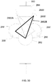
- the hyperdexterous surgical arm can be positioned to establish a Remote Center.
- the Remote Center is the location where entry into the body occurs.
- the Remote Center is a location in space where the axes of rotation of the various roll and pitch mechanisms of the hyperdexterous surgical arm and the axis of the hyperdexterous surgical tool intersect.
- the Remote Center can be located at the incision of a patient.
- the shoulder roll mechanism can be placed below the Remote Center to position the dead zone outside the body of the patient.
- the hyperdexterous surgical arm can include a pitch mechanism, a first roll mechanism, and a second roll mechanism.
- the axis of the first and second roll mechanism can pass through the Remote Center.
- an axis of a hyperdexterous surgical tool coupled to the hyperdexterous surgical arm can pass through the Remote Center.
- the hyperdexterous surgical arm can be arranged such that the vertical location of the second roll mechanism can be at or below the Remote Center through which all the axes pass.
- the second roll mechanism is the redundant roll mechanism.
- the hyperdexterous surgical arm can be arranged such that the second roll mechanism can rotate at least up to +/- 90° from an initial position. In some embodiments, the hyperdexterous surgical arm can be arranged such that the second roll mechanism can rotate more than +/- 90° from an initial position.
- the second roll mechanism can advantageously reach targets that are inaccessible or difficult to reach with an on-market robotic arm having only the pitch mechanism and one roll mechanism.
- the hyperdexterous surgical arm can assume various poses.
- the target location may be accessed by changing the orientation of the pitch mechanism, the first roll mechanism, and/or the second roll mechanism while maintaining Remote Center.
- the hyperdexterous surgical system includes a rotate/translate mechanism that can impart rotation and/or translation on a hyperdexterous surgical tool.
- the hyperdexterous surgical arm can be arranged such that the rotate/translate mechanism is located proximate the Remote Center (e.g., within 7.6-12.7 cm, within 5.1-15.2 cm, within 2.5-17.8 cm, less than 17.8 cm, less than 15.2 cm, less than 12.7 cm, less than 10.2 cm, less than 7.6 cm, less than 5.1 cm, less than 2.5 cm) (e.g., within 3-5 inches, within 2-6 inches, within 1-7 inches, less than 7 inches, less than 6 inches, less than 5 inches, less than 4 inches, less than 3 inches, less than 2 inches, less than 1 inch).
- the Remote Center e.g., within 7.6-12.7 cm, within 5.1-15.2 cm, within 2.5-17.8 cm, less than 17.8 cm, less than 15.2 cm, less than 12.7 cm, less than 10.2 cm, less than 7.6 cm, less than
- the rotate/translate mechanism can be arranged to have a limited contribution to rotational moment of inertia of the hyperdexterous surgical arm.
- the rotate/translate mechanism can be arranged to limit interference with adjacent hyperdexterous surgical arms during movement.
- the rotate/translate mechanism can be arranged such that it acts directly on the shaft of the hyperdexterous surgical tool.
- the rotate/translate mechanism can be arranged such that it accommodates different size shafts of the hyperdexterous surgical tools.
- the rotate/translate mechanism can have a smaller width than on-market systems, allowing hyperdexterous surgical tools of adjacent hyperdexterous surgical arms to be positioned close together.
- the rotate/translate mechanism can be arranged such that the mechanical energy inputs for rotation and translation can be differential such that rotation and/or translation are achieved by combined motion of the two mechanical energy inputs.
- the mechanical energy inputs for rotation and translation can be differential such that the power applied to the mechanism is the combined power of the two input motors.
- the rotate/translate mechanism can be arranged such that it maintains a barrier between sterile components of the hyperdexterous surgical system and non-sterile components of the hyperdexterous surgical system.
- the rotate/translate mechanism can be arranged such that the shaft position of the hyperdexterous surgical tool is measured directly on the shaft through the resistance or capacitance of the shaft length outside the body of the patient.
- the hyperdexterous surgical system can include a control system.
- the hyperdexterous surgical arm can be controlled by an input device.
- the hyperdexterous surgical tool can be controlled by an input device.
- the position and orientation of the input device can be tracked.
- the input device can be wireless or wired.
- the hyperdexterous surgical system can include one or more input devices (e.g., two, three, four, five, six input devices, etc.).
- the input devices can control one or more control points.
- the control points are locations which have the capability to execute some motion.
- One or more control points can be located on the hyperdexterous surgical arm.
- One or more control points can be located on the hyperdexterous surgical tool.
- the conversion of movement of the input device to movement of one or more control points may be independent of the movement of other control points.
- the conversion of movement of the input device to movement of one or more control points may be synchronized with the movement of other control points.
- the operator can control one or more control points simultaneously.
- the controlled objects may be selected from the group comprising one or more hyperdexterous surgical tools and/or one or more hyperdexterous surgical arms.
- the control system of the hyperdexterous surgical system can convert the movement of the input device into movements of the controlled objects dependent on the zoom factor of images displayed on one or more displays.
- the control system can include the application of constraints between the one or more input devices and the one or more controlled objects.
- the control system can be arranged such that the constraints are measured quantities such as position or derived parameters such as distance, velocity, force, and tension.
- the control system can be arranged such that the constraints can be different for each controlled object.
- the control system can be arranged such that the constraints can be the same for a group of controlled objects.
- Each hyperdexterous surgical tool in the set can have an independent constraint.
- the constraint can be that one or more hyperdexterous surgical tools can be manipulated together with a single input device.
- the hyperdexterous surgical system can include an electronic control system that communicates with the one or more hyperdexterous surgical arms and/or one or more hyperdexterous surgical tools.
- the hyperdexterous surgical system can include one or more input devices that communicate a signal with the control system.
- the signal from the input devices can be transmitted within the operating arena.
- the signal from the input devices can be transmitted from the bedside of a patient, allowing the operator to control hyperdexterous surgical arm from the bedside of a patient.
- the control system can communicate a signal with the one or more hyperdexterous surgical arms and/or one or more hyperdexterous surgical tools from various locations within the operating arena.
- the hyperdexterous surgical system enables the control of a hyperdexterous surgical tool and a manual tool in frames of reference that are aligned, partially aligned or independent of each other.
- the hyperdexterous surgical system enables control of one or more hyperdexterous surgical tools in frames of reference that are aligned, partially aligned or independent of each other.
- the hyperdexterous surgical system provides information to the operator regarding the frames of references.
- the hyperdexterous surgical system enables the movement of a hyperdexterous surgical tool to be locked to the movement of a single tool.
- the hyperdexterous surgical system enables the movement of one or more hyperdexterous surgical tools to be locked to the movement of a single hyperdexterous surgical tool.
- the hyperdexterous surgical system enables the movement of one or more hyperdexterous surgical tools to be locked to the movement of a single manual tool.
- the hyperdexterous surgical system enables and disables motion of one or more hyperdexterous surgical tools with a mechanism.
- the mechanism can be a clutch.
- the operation of the mechanism can establish a frame of reference for the hyperdexterous surgical tool.
- the operation of the mechanism enables the operator to establish a new reference frame after the initial establishment of a reference frame.
- the hyperdexterous surgical system can be arranged such that the frame of reference may be associated with the wrist or forearm of the operator's hand that is operating the input device.
- the hyperdexterous surgical system can be arranged such that the frame of reference may be associated with the wrist or forearm of the operator's hand that is operating the manual tool.
- the operator can manipulate one or more hyperdexterous surgical tools in a frame of reference that is independent of the frame of reference of the one or more manual tools.
- the hyperdexterous surgical system facilitates an understanding of the frames of references.
- the hyperdexterous surgical system includes a visualization system that aggregates information from one or more sources and provides one or more images to the surgeon.
- the information may be positional information of the surgeon, the patient, the hyperdexterous surgical arm, the hyperdexterous surgical tool, and/or the manual tool.
- the information may be positional information of control points.
- the image can be manipulated to reflect the point of view of the surgeon.
- the image can be updated to reflect the point of view of the surgeon as the surgeon moves to another location.
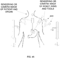
- the information presented by the visualization system may be live data from the cameras, data from pre-operative MRI, CT, ultrasound or other imaging modality, and models of organs and other parts of the human body.
- the visualization system can be arranged such that the image can be updated in real time as data from cameras is received.
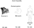
- the visualization system can be arranged such that the image can be a blend of information from various sources. The blending and the types of information to blend may depend on the zoom factor.
- the image can be updated to display warnings related to the information (e.g., non-real-time, not precisely aligned models, low-resolution data).
- the visualization system can present an image on one or more displays.
- the image displayed on each display may be different.
- Each display may present different images (e.g., the location of the patient, the location of control points).
- the visualization system can be arranged such that the images can be adjusted automatically dependent on the type of manipulation being performed.
- the visualization system can be arranged such that the images may be rotated and oriented according to the surgeon's location.
- the visualization system can be arranged such that during the zooming operation, the images can be blended to transition smoothly between a zoomed in image and a zoomed out image.
- the images may be controlled by the user input devices.
- hyperdexterous is a combination of the ordinary meaning of "hyper” and “dexterous”; hyper meaning over or above, and dexterous meaning skillful or adroit in the use of the hands or body.
- a hyperdexterous surgical system as used herein enables interactions between a surgeon and the patient along an interaction continuum, as further described below, and provides increased versatility with respect to the surgical procedures that can be performed.
- the hyperdexterous surgical system enhances the ability of the surgeon to interact with a patient and includes several features which combine to produce a more natural, more interactive, and more versatile surgical system.
- the versatility of the hyperdexterous surgical system is illustrated by various aspects of the system, such as for example its modularity, which allows the use of one or more hyperdexterous surgical arms and to move the hyperdexterous surgical arm out of the way to utilize only manual surgical tools, its enabling of the surgeon to be mobile in the surgical arena during a surgical procedure, and its enabling of the surgeon to simultaneously operate a hyperdexterous surgical tool and a manual tool while being able to maneuver between multiple bedside locations of the patient to an optimal position for a particular surgical task.
- a hyperdexterous surgical system has more versatility than on-market purely "robotic" surgical systems.
- hyperdexterous surgical system is illustrated, among other ways, by providing the surgeon with a variety of information (e.g., via displays) that allow the surgeon to readily understand the positioning of the hyperdexterous surgical tools relative to the patient so as to naturally understand how the tools will move when actuated.
- the interactive nature of the hyperdexterous surgical system is illustrated, among other things, by the ability of the surgeon to selectively control a plurality of hyperdexterous surgical tools with user input devices, as well as the ability to move between different frames of reference during a surgical procedure (e.g., between an immersive frame of reference inside the patient's body and a frame of reference outside the patient's body), allowing the surgeon to reposition himself or herself during a procedure, all the while remaining aware of the position and orientation of the tools relative to the surgeon.
- a surgical procedure e.g., between an immersive frame of reference inside the patient's body and a frame of reference outside the patient's body
- the hyperdexterous surgical system described herein provides a fundamentally different conceptual framework from existing on-market robotic surgical systems in that, among other things, it enables a surgeon to simultaneously use manual and hyperdexterous surgical tools while at the patient's bedside.
- This ability to be at the patient's bedside, i.e., beside the operating table, provides several advantages: from improved communication with the surgical team; to direct monitoring of the patient; to facilitating tool exchanges (e.g., between manual and hyperdexterous surgical tools).
- the hyperdexterous surgical system includes several subsystems that together provide a flexible, more natural, and more interactive system that advantageously allows surgeons to perform surgical procedures seamlessly along an interaction continuum between using only hyperdexterous surgical tools, simultaneously using a combination of manual and hyperdexterous surgical tools, and using only manual tools as desired by the surgeon or required by the surgical task.
- hyperdexterous surgical system is the size of the hyperdexterous surgical arm, which is smaller and more compact than those of on-market systems, and which allows increased flexibility in how the arm is mounted relative to the patient - whether on a cart, or dolly, or wall or ceiling of the operating room, or directly to the patient's bed.
- the smaller size of the hyperdexterous surgical arm also allows for the hyperdexterous surgical system to be modular, where the number of hyperdexterous surgical arms used can vary as desired by the surgeon depending on the surgical need.
- the small size of the hyperdexterous surgical arms additionally provide for increased free space above the patient, which facilitates the surgeon's ability to work from a bedside location.
- one inventive aspect of the hyperdexterous surgical system is that it allows the surgeon to operate along an interaction continuum, and in one scenario the surgeon can move the hyperdexterous surgical arms out of the way and use only manual tools.
- This ability to maximize the free space e.g., move the hyperdexterous surgical arms out of the way, small size of the arm
- the redundant roll of the hyperdexterous surgical arm is advantageously positioned so as to ensure that a dead zone for the hyperdexterous surgical tool is located outside the body of the patient, thereby allowing for increased access of the hyperdexterous surgical tool within the workspace in the body.
- the rotation and translation mechanism for the hyperdexterous surgical tool advantageously facilitates the small size of the hyperdexterous surgical arm, as discussed below.
- the rotate/translate system is smaller in diameter, lighter and more compact than mechanisms that impart rotation and translation for on-market systems, which allows the hyperdexterous surgical arm that supports the rotate/translate mechanism to be smaller.
- hyperdexterous surgical system Another advantageous and interrelated aspect of the hyperdexterous surgical system is the ability it provides to the surgeon to move around freely and position him or herself in an optimal position near the patient. This ability is provided by the hyperdexterous surgical system in several ways, including allowing the surgeon to control the hyperdexterous surgical arm with one or more handheld portable input devices that communicate the movements of the surgeon's hands to a control system that controls the operation of the hyperdexterous surgical arm and hyperdexterous surgical tool.
- the handheld portable input devices are wireless.
- the hyperdexterous surgical system advantageously provides for tracking of the handheld portable input devices, as well as features (e.g., a clutch) to prevent unintended motion of the hyperdexterous surgical arms or hyperdexterous surgical tools due to movements of the surgeon.
- control system which communicates the surgeon's commands (e.g., via the user input devices) to the hyperdexterous surgical tools and hyperdexterous surgical arms and facilitates how the surgeon interacts with the hyperdexterous surgical tools and hyperdexterous surgical arms.
- visualization system which aids the surgeon in manipulating the hyperdexterous surgical tools within the patient's body from various frames of reference (e.g., immersive, bird's eye view outside the patient's body).
- the control system and visualization system may work together to enhance the surgeon's ability in performing a surgical procedure by providing a variety of information (e.g., visual cues) that allows the surgeon to naturally recognize the positioning of the hyperdexterous surgical tools and manual tools.
- Each of the components or subsystems of the hyperdexterous surgical system have advantages over corresponding components in on-market systems. Additionally, taken together the components and subsystems provide a hyperdexterous surgical system that provides a completely different paradigm for surgical procedures that enhances the ability of the surgeon to interact with a patient in a more natural, more interactive, and more flexible manner.
- the hyperdexterous surgical system will now be described in more detail.
- Figure 1A shows the interaction continuum of the hyperdexterous surgical system.
- the right end of the continuum illustrates physical interactions between the body of the surgeon and the body of the patient.
- the far right end of the continuum includes the surgeon moving tissue by hand.
- the use of a manual tool such as a scalpel is less physically interactive than moving tissue by hand.
- the use of a laparoscopic tool such as a scalpel is less physically interactive than moving tissue by hand.
- the left end of the continuum illustrates the use of a hyperdexterous surgical arm to control end effectors.
- the operator can use manual tools and/or hyperdexterous tools in various combinations.
- the hyperdexterous surgical system enables an operator 1, such as a surgeon, to work anywhere along the continuum.
- the surgeon is in close proximity to the patient in order to physically manipulate the tissue.
- the surgeon is able to directly touch and feel tissue at the surgical site.
- the surgeon interacts with the patient remotely by manipulating user input devices that serve as proxies for the real tools.
- the surgeon manipulates end-effectors such as graspers by manipulating user input devices. Many scenarios occur along the interaction continuum.
- Embodiments herein describe the use of a hyperdexterous surgical system that can be used by an operator.
- the operator may be a surgeon, a medical assistant, staff, medical examiners, or any other person operating the hyperdexterous surgical system.
- An operator is not limited to a medical professional qualified to practice surgery, but includes any operator trained to operate the hyperdexterous surgical system.
- Figure 1B replicates the interactive continuum of Figure 1A in more detail.
- Figure 1B shows various methods of using a hyperdexterous surgical system, such as the hyperdexterous surgical system 100 shown in Figure 2 .
- an operator 1 may perform a surgical step with manual tools 350.
- a hyperdexterous surgical arm 200 of the hyperdexterous surgical system 100 may be moved away from the work space.
- the operator 1 may refer to a display 702 which provides images of the surgery.
- the operator 1 interacts with an input device 500 to control the hyperdexterous surgical arm 200.
- the operator 1 may refer to a display 600 which provides images of the surgery.
- Scenario 1 in Figure 1B .
- the operator 1 may simultaneously use one or more hyperdexterous surgical tools 300 and one or more manual tools 350 (e.g., at the same time, in the same workspace).
- the surgeon can manipulate one or more of the hyperdexterous surgical tools 300 with one or more of the input devices 500.
- the operator 1 may refer to a display 702 which provides images of the surgery.
- Scenario 2 in Figure 1B .
- the operator 1 may manipulate the hyperdexterous surgical arm 200 by hand. This scenario may occur for example when executing large scale motions of the hyperdexterous surgical arms 200.
- Figure 1B shows only one hyperdexterous surgical arm 200, the hyperdexterous surgical system 100 can have a plurality of hyperdexterous surgical arms 200, as shown in Figure 2 .
- the operator 1 can insert the manual tool 350 into a trocar 302 (shown in Figure 2 ) supported by the hyperdexterous surgical arm 200.
- the trocar 302, with the manual tool 350 inserted therein, may be manipulated by hand.
- the third scenario may be useful when it may be difficult to maneuver the manual tool 350 only with the hands. Some examples where such situations may be encountered is when the patient is obese or if the angle of entry into the patient is awkward. In such situations the hyperdexterous surgical arm 200 holding the trocar 302 may act as a power assist to position the manual tool 350.
- the hyperdexterous surgical arm 200 holding the trocar 302 may counter the forces that are applied on the manual tool 350 by the patient's body, and can enhance maneuverability of the manual tool 350.
- the versatility of the hyperdexterous surgical system 100 advantageously allows all such combinations.
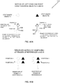
- Figures 3A-3C shows scenarios wherein the operator 1 selects the type of tools to be used in a surgical procedure.
- Figure 3B is similar to Scenario 1 and Figure 3C is similar to the left side of the continuum shown in Figure 1B .
- the figures show three dimensional depiction of use the hyperdexterous surgical system 100 during a surgical procedure on a patient 2.
- the hyperdexterous surgical system 100 includes two hyperdexterous surgical arms 200, each coupled to a hyperdexterous surgical tool 300.
- the operator 1 controls a hyperdexterous surgical arm 200 with an input device 500 held in his right hand.
- the operator 1 controls another hyperdexterous surgical arm 200 with an input device 500 held in his left hand.
- the input devices 500 move the hyperdexterous surgical arms 200 and/or the hyperdexterous surgical tools 300 in response to the operator's 1 movement.
- the hyperdexterous surgical system 100 includes a display 600.
- the display 600 may allow the operator 1 to establish constraints to be applied to the hyperdexterous surgical system 100.
- the display 600 may allow the operator 1 to establish associations (e.g., a pairing) between the input devices 500 and the controlled objects (e.g., the hyperdexterous surgical arms 200 and/or the hyperdexterous surgical tools 300).
- the display 600 may provide images of the surgery.
- the hyperdexterous surgical system 100 includes a hyperdexterous surgical arm 200 coupled to a hyperdexterous surgical tool 300.
- the operator 1 controls the hyperdexterous surgical arm 200 with an input device 500 held in his right hand.
- the input device 500 moves the hyperdexterous surgical arm 200 and/or the hyperdexterous surgical tool 300 in response to the operator's 1 movement.
- the operator 1 controls a manual tool 350 with his left hand.
- the hyperdexterous surgical system 100 advantageously enables the operator 1 (e.g., surgeon) to simultaneously control a hyperdexterous surgical tool 300 and a manual tool 350.
- the hyperdexterous surgical system 100 includes two hyperdexterous surgical arms 200, each coupled to a hyperdexterous surgical tool 300.
- the operator 1 can control the hyperdexterous surgical arms 200 with one or more input devices 500.
- the input devices 500 can be the input devices shown in Figure 3A .
- the input devices 500 can be controllers as shown in Figure 3C .
- the one or more input devices 500 can be mounted or otherwise fixed near the display 600.
- the one or more input devices 500 can be handheld portable input devices, such as those shown in FIG. 3A , and the operator 1 can support his or her arms on a support bar or rest bar of the stand while standing or sitting at the stand and operating the handheld portable input devices.
- the one or more input devices 500 shown in Figure 3C moves the hyperdexterous surgical arms 200 and/or the hyperdexterous surgical tools 300 in response to the operator's 1 movement.
- the hyperdexterous surgical system 100 can include many components that can work together to achieve benefits described herein, such as enhancing the ability of the surgeon to interact with the patient by providing a more natural, more interactive, and more versatile surgical system.
- the hyperdexterous surgical system 100 can include one or more hyperdexterous surgical arms 200, and each hyperdexterous surgical arms 200 can manipulate a hyperdexterous surgical tool 300.
- the hyperdexterous surgical system 100 includes a control system and displays 600, 702 which provide the operator with visual cues that aid the surgeon in controlling the operation of the one or more hyperdexterous surgical tools 300 and the manual tools 350.
- the operator such as a surgeon can optionally manipulate the hyperdexterous surgical tool 300 and the manual tools 350 simultaneously at various locations in the operating arena.
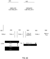
- FIG 2 shows one embodiment of a hyperdexterous surgical system 100.
- the hyperdexterous surgical system 100 includes one or more hyperdexterous surgical arms 200. Each hyperdexterous surgical arm 200 can support a hyperdexterous surgical tool 300 (e.g., via a trocar 302).
- the hyperdexterous surgical system 100 can include one or more manual tools 350.
- the manual tool 350 can be used simultaneously with the hyperdexterous surgical tool 300 by the operator (e.g., surgeon).
- the hyperdexterous surgical tool 300 can be controlled by an input device 500.
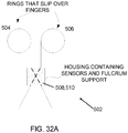
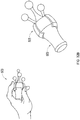
- the input device 500 can take many forms including a pincher 502 (see Figure 32A ) and a controller 514.
- the hyperdexterous surgical system 100 can include a control system to translate movements from the input devices 500 to movements of the hyperdexterous surgical arms 200 and hyperdexterous surgical tool 300.
- the operator 1 can select which input device 500 controls which hyperdexterous surgical tool 300 or hyperdexterous surgical arms 200.
- the control system 400 can include a computer 402, one or more cables 406 and/or a power supply 404.
- the hyperdexterous surgical arm 200 can be coupled with a fixture (e.g., operating table, hospital bed, examination table, wall, floor, ceiling, table, cart, dolly).
- a fixture e.g., operating table, hospital bed, examination table, wall, floor, ceiling, table, cart, dolly
- the fixture can be anchored (e.g., temporarily) to the floor.
- the hyperdexterous surgical system 100 may include mechanisms that couple or hold the hyperdexterous surgical arm 200 to the fixture.
- the fixture is a bed or operating table 102.
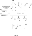
- the hyperdexterous surgical arm 200 and the hyperdexterous surgical tool 300 can be controlled by a control system 400, a schematic of which is shown in Figures 34-35 .
- the algorithms that guide the control system and/or any computations performed by the control system may be stored by the computer 402.
- the control system 400 can translate user commands to motion of the hyperdexterous surgical arm 200 and/or motions of the hyperdexterous surgical tool 300.
- the computer 402 may be connected to the power supply 404.
- the computer 402 may be connected to a clutch 112 which may take the form of a foot pedal.
- the computer 402 may include cables 406 that connect the computer 402 to other components.
- the hyperdexterous surgical system 100 can include one or more input devices 500.
- the input device 500 can communicate with the control system 400, either through a wired or wireless connection.
- the term “wireless” encompasses all forms of wireless communication, including, but not limited to, infrared (IR), radiofrequency (RF), microwave, and ultrasonic.
- the input device 500 can send control signals to the appropriate motors within the hyperdexterous surgical arm 200 and the hyperdexterous surgical tools 300 via the control system 400 (e.g., by communicating a signal from a transmitter in the input device 500 to a receiver of the control system 400).
- the input devices 500 can be handheld and/or portable devices that advantageously allow the operator 1, such as a surgeon, to move about the bedside of the patient 2 during a procedure.
- the input devices 500 can allow the operator 1 to control the hyperdexterous surgical arm 200 and/or the hyperdexterous surgical tools 300 from one or more locations (e.g., a plurality of locations). Some of the locations may be at the bedside of a patient 2.
- the hyperdexterous surgical system 100 can include the clutch 112.
- the clutch 112 can be used to engage or disengage one or more hyperdexterous surgical tools 300.
- the clutch 112 can be a foot pedal, as shown in Figure 2 .
- the hyperdexterous surgical system 100 can include a user interface sub-system 605.
- the user interface sub-system 605 can include an input device (e.g., controller 514).
- the user interface sub-system 605 can include a platform 602 which can include features such as a horizontal resting bar 603.
- the user interface sub-system 605 can include a display 600.
- the display 600 can include a touch screen 604.
- the display 600 can be interactive and receive an input from the operator 1.
- the display 600 can be used to control the control system 400.
- the display 600 can be located remotely from the patient.
- the display 600 is mounted onto the platform 602, as shown in Figure 2 .
- the display 600 can be affixed to the body of the operator 1, such as the surgeon.
- the user interface sub-system 605 can include an input device 500 (e.g., a wired controller).
- the input device 500 may be a controller 514 mounted to the platform 602.
- the user interface sub-system 605 allows an operator 1, such as a surgeon, to control the input device 500 in close proximity to the display 600, as shown in Figure 2 .
- the display 600 allows the operator 1 to perform many functions including pairing a hyperdexterous surgical tool 300 with an input device 500 so that the operator 1 can operate the paired hyperdexterous surgical tool 300 with the input device 500.
- the display 600 can allow the operator 1 to control one or more hyperdexterous surgical tools 300 with the one or more input devices 500.
- the display 600 also allows the operator 1, such as a surgeon, to pair a hyperdexterous surgical arm 200 with an input device 500 so that the operator 1 can operate the paired hyperdexterous surgical arm 200 with the input device 500.
- the display 600 can allow the operator 1 to control one or more hyperdexterous surgical arms 200.
- the user interface 600 can show or illustrate a map of the one or more input devices 500 and the one or more controlled objects, such as the one or more hyperdexterous surgical arms 200 or hyperdexterous surgical tools 300.
- a visualization system 700 can include one or more displays 702.
- the display 702 can display information about the one or more hyperdexterous surgical arms 200, the one or more hyperdexterous surgical tools 300, the patient, or any other information that may be relevant to the surgeon or surgical team.
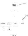
- the display 702 can show images as seen by a camera 304 (shown schematically in Figure 35 ) or other visualization devices, such as images of the hyperdexterous surgical tools 300 that are held by the hyperdexterous surgical arms 200, or images of a manual tool 350 held by the operator (e.g., surgeon).
- the camera 304 can be controlled by the control system 400.
- the camera 304 can be considered a hyperdexterous surgical tool 300 and moved by a hyperdexterous robotic arm 200.
- the camera 304 can be controlled by the input device 500 via the control system 400, which enables the operator 1, such as the surgeon, to position the camera 304 as needed.
- the hyperdexterous surgical system 100 can include multiple displays 702 positioned at various locations throughout the operating arena. Additionally, the displays 600, 702 can show the same information or different information.
- the hyperdexterous surgical system 100 can be used with one or more manual tools 350 (e.g., a plurality of manual tools 350).
- One manual tool 350 is shown in Figure 2 .
- the manual tool 350 can be utilized in the same work space as the one or more hyperdexterous surgical tools 300.
- One or more manual tools 350 can be used because the hyperdexterous surgical system 100 advantageously allows the operator 1 to stand right by the patient 2, as discussed previously.
- One or more manual tools 350 can be used because the hyperdexterous surgical arm 200 is compact, thereby freeing up the space around the patient 2.
- the redundant roll mechanism and the placement of the redundant roll mechanism, described herein, also maximizes the free space around the patient 2.
- the operator 1 can simultaneously manipulate hyperdexterous surgical tools 300 and manual tools 350 without colliding into other components of the hyperdexterous surgical system 100.
- the operator 1, not shown in Figure 2 may stand by the bedside, and have the ability to choose to control one or more hyperdexterous surgical tools 300 (e.g., via the input devices 500), one or more manual tools 350, or any combination of hyperdexterous surgical tools 300 and manual tools 350.
- the hyperdexterous surgical arm 200 can be coupled to a hyperdexterous surgical tool 300.
- the system 100 can have one or more (e.g. a plurality) of hyperdexterous surgical arms 200 and one or more (e.g. a plurality) of hyperdexterous surgical tools 300.
- the hyperdexterous surgical tool 300 is inserted into a trocar 302.
- the trocar 302 can be coupled to the hyperdexterous surgical arm 200 (e.g., affixed, integrally formed with, held by, etc.).
- the hyperdexterous surgical arm 200 can support and manipulate the hyperdexterous surgical tools 300 through the trocar 302.
- the one or more hyperdexterous surgical arms 200 can insert one or more hyperdexterous surgical tools 300 through an incision in a patient 2, as shown in Figures 3A-C .
- the hyperdexterous surgical arm 200 and the hyperdexterous surgical tool 300 can have one or more motors (e.g., electrical motors) at various locations, as discussed further below.
- the motors facilitate the placement of the hyperdexterous surgical tools 300 appropriately in the operating work space, inside the patient 2.
- the hyperdexterous surgical arm 200 and the hyperdexterous surgical tool 300 can be powered by the power supply 404.
- the one or more hyperdexterous surgical tools 300 can be disposable.
- at least a portion of the hyperdexterous surgical tools 300 can be capable of being sterilized (e.g., reusable).
- the hyperdexterous surgical system 100 can provide a mounting to support the hyperdexterous surgical arm 200.
- the mounting enables the positioning of the hyperdexterous surgical arm 200 and/or the hyperdexterous surgical tools 300 relative to the patient.
- the hyperdexterous surgical arm 200 can be mounted to a number of fixtures, which may be movable or fixed.
- the flexibility in mounting the hyperdexterous surgical arm 200 and/or the hyperdexterous surgical tools 300 provides versatility in designing the operating arena and the free space outside the patient.
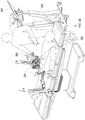
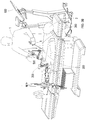
- Figures 2 and 4 show embodiments of the hyperdexterous surgical arm 200 mounted to a fixture.
- the various components allow the hyperdexterous surgical arm 200 to be positioned relative to the patient 2.
- the various components also allow the hyperdexterous surgical arm 200 to avoid collisions with other hyperdexterous surgical arms 200.
- the hyperdexterous surgical arm 200 can be positioned to facilitate access to the patient 2.
- the hyperdexterous surgical arm 200 can be positioned to permit the operator 1 to use hyperdexterous surgical tools 300 and manual tools 350 simultaneously.
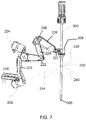
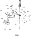
- the flexibility of the hyperdexterous surgical system 100 including the support arm 106, the elevator 120, and the carriage 130 allows the positioning of a Remote Center 250 (see Figure 7 ) for the hyperdexterous surgical arm 200. Once the Remote Center 250 is established, the hyperdexterous surgical arm 200 can be manipulated while maintaining the Remote Center 250.
- the hyperdexterous surgical system 100 can include a plurality of mounting poles 104.
- the hyperdexterous surgical system can include any number of mounting poles 104 (e.g., one, three, four, etc.), but two are shown in Figure 2 for illustrative purposes.
- Each mounting pole 104 can support a hyperdexterous surgical arm 200.
- Figure 2 shows each mounting pole 104 only holding one hyperdexterous surgical arm 200, but each mounting pole 104 can optionally support any number of hyperdexterous surgical arms 200 (e.g., one, two, three, four, etc.).
- the hyperdexterous surgical system 100 is advantageously modular in nature.
- This modularity allows the users, such as a surgical team, to configure the hyperdexterous surgical system 100 most efficiently for the type of procedure being performed. Such modularity also allows the team to add or remove mounting poles 104 and/or hyperdexterous surgical arms 200 during a surgery. The modularity permits the hyperdexterous surgical system 100 to be configured in various ways.
- the mounting pole 104 may be supported by a movable fixture (e.g., a dolly, a hand-truck or a small cart).
- the mounting pole 104, and all associated hyperdexterous surgical arms 200 and support arms 106, may be mounted to the moveable fixture at a location remote from the operating arena.
- the movable fixture may be transported into the operating arena before or during the surgery. If additional hyperdexterous surgical arms 200 are needed during surgery, the hyperdexterous surgical arm 200 can be mounted quickly and easily onto the fixture. In some embodiments, if additional hyperdexterous surgical arms 200 are needed during surgery, additional hyperdexterous surgical arms 200 mounted on movable fixtures may be transported into the operating arena.
- the moveable fixture and/or the mounting pole can be anchored to another fixture (e.g., the floor) to enhance stability.
- the mounting pole 104 may be supported by an immobile fixture (e.g., bed, floor, wall, or ceiling).
- the mounting pole 104 can be attached to a clamp 108, as shown in Figure 2 .
- the clamp 108 can be connected to the fixture.
- the fixture is a bed 102, though as discussed above, other suitable fixtures can be used.
- the clamp 108 can be coupled to one or more rails 110 of the bed 102.
- Other attaching mechanisms are possible.
- the mounting pole 104 may be placed substantially vertically (e.g., at ninety degrees) relative to the fixture (e.g., bed 102).
- the mounting pole 104 may be placed at other angles, such as 15 degrees, 30 degrees, 45 degrees, 60 degrees, relative to the fixture (e.g., bed 102).
- the mounting pole 104 can be placed at other angles based on the orientation of the patient.
- the hyperdexterous surgical arm 200 can be directly or indirectly attached to the fixture (e.g., bed 102).
- the mounting pole and/or the support arm 106 is excluded and the hyperdexterous surgical arm 200 can be coupled directly to the mounting pole 104 or to a portion of the fixture (e.g., bed 102).
- the hyperdexterous surgical system 100 can be detached from the fixture (e.g., bed 102 and/or rail 110).
- the mounting pole 104 can be coupled to components that permit horizontal movement (e.g., parallel to the bed 102) or vertical movement (e.g., perpendicular to the bed 102).
- the elevator 120 allows the placement of the support arm 106 and/or the hyperdexterous surgical arm 200 along the length of the mounting pole 104.
- One or more elevators 120 may be coupled to the mounting pole 104, as shown.
- Each elevator 120 may be connected to an additional support arm 106 and/or an additional hyperdexterous surgical arm 200.
- the mounting pole 104 can optionally support multiple support arms 106, each support arm 106 coupled to a hyperdexterous surgical arm 200.
- the elevators 120 may provide alternative vertical locations at which the hyperdexterous surgical arm 200 may be coupled to the mounting pole 104.
- the mounting pole 104 can be coupled to a carriage 130.
- the carriage 130 may be coupled to an adaptor 132.
- the carriage 130 and the adaptor 132 may form a slide assembly that allows the carriage 130 to slide linearly along the adaptor 132.
- the adaptor 132 can be coupled to the fixture (e.g., bed 102 and/or the rail 110).
- the carriage 130 may be directly coupled to the fixture (e.g., bed 102 and/or rail 110) without the adaptor 132.
- the carriage 130 and the adaptor 132 permit the movement of the mounting pole 104, the support arm 106, and the hyperdexterous surgical arm 200 in the generally horizontal direction.
- the mounting pole 104 directly couples to the fixture (e.g., bed 102 and/or the rails 110) without the carriage 130 and/or the adaptor 132.
- the mounting pole 104 can be arranged such that the mounting pole 104 slides linearly along the fixture (e.g., bed 102 and/or the rails 110).
- the mounting pole 104 can be coupled to components that permit movement in other directions.
- the mounting pole can be coupled to a slide (not shown) that moves orthogonal to the horizontal and vertical direction (e.g., extends outward from the fixture).
- the slide can be a drawer mounted to the fixture.
- the hyperdexterous surgical arm 200 can be moved laterally away from a side of the bed 102 (e.g., via a slidable drawer).
- the hyperdexterous surgical system 100 can include mechanisms that couple or hold the hyperdexterous surgical arms 200 upright.
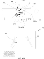
- Figures 2 and 4 shows the hyperdexterous surgical arm 200 optionally coupled to a support arm 106.
- the support arm 106 can be a passive arm, lacking motors or other electrical features.
- the support arm 106 has a first end 114 and a second end 116.
- the first end 114 can include a bracket 118, such as a u-shaped bracket, that can be coupled to the hyperdexterous surgical arm 200.
- Other connections known in the art can also be utilized.
- the bracket 118 can couple to the hyperdexterous surgical arm 200 at the base of the hyperdexterous surgical arm 200, for example near a shoulder roll mechanism 202 (see Figure 7 ), described further below.
- the second end 116 can be coupled to the elevator 120.
- the second end 116 can rotate about a center of rotation 122.
- the support arm 106 may include one or more centers of rotation that allow the support arm 106 to rotate.
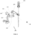
- the support arm 106 shown in Figure 5 has three centers of rotation 122.
- the centers of rotation 122 rotate about an axis in the direction of the arrows, as shown in Figure 5 .
- the support arm 106 may include one or more tilt axes 124 which allow a portion of the support arm 106 to tilt.
- the support arm 106 has one tilt axis 124 that allows a hyperdexterous surgical arm 200 coupled to the support arm 106 to tilt.
- the centers of rotation 122 and/or the tilt axis 124 allow the one or more links 126 of the support arm 106 and the bracket 118 to be rotated and positioned.
- the centers of rotation 122 may rotate the links 126 of the support arm 106 in the same plane, or in different planes, or in some combination of planes.
- the support arm 106 can be passive. The operator 1 can move the support arm 106 by hand to position the support arm 106. The operator 1 can move the support arm 106 by hand to establish the Remote Center 250, described herein. In some embodiments, the support arm 106 can be active. In such an embodiment, the support arm 106 can include one or more motors to move joints of the support arm 106. The operator 1 can move the support arm 106 via the motors to establish the Remote Center 250.
- the hyperdexterous surgical system 100 provides flexibility in positioning the hyperdexterous surgical arm 200 and/or the hyperdexterous surgical tool 300.
- the flexibility is advantageously enhanced by the centers of rotation 122 and/or tilt axes 124 of the support arm 106, shown in Figure 5 .
- the flexibility can be enhanced by the ability to move (e.g., vertically) the elevator 120 along the mounting pole 104.
- the flexibility can be enhanced by the ability to move (e.g., horizontally) the carriage 130 along the adaptor 132.
- the support arm 106, the elevator 120, and the carriage 130 can facilitate the positioning of the hyperdexterous surgical arm 200.
- Arrow 134, Arrow 136, Arrow 138 and Arrow 140 demonstrate the centers of rotations and tilt axes of the support arm 106.
- Arrow 142 demonstrates the generally vertical direction the elevator 120 may be positioned along the mounting pole 104.
- Arrow 144 demonstrates the generally horizontal direction the carriage 130 may move along the adaptor 132 in relation to the fixture (e.g., bed 102 and/or rails 110).
- the mounting pole 104 may be vertical, and the adaptor 132 may be horizontal; hence Arrow 142 may be vertical and Arrow 144 may be horizontal. All of the arrows or degrees of freedom can be configured differently than shown in Figure 6 (e.g. the support arm 106 can have more or fewer centers of rotations or tilt axes).
- the hyperdexterous surgical system 100 can enable the one or more hyperdexterous surgical arms 200 to be angled (e.g., tilt) to follow an orientation of a patient during the course of the surgery.
- the patient is placed on a horizontal level surface (e.g., bed).
- it may be advantageous to angle (e.g. tilt) the body of the patient relative to the horizontal surface e.g., lowering the head of the patient to shift internal organs toward the head of the patient away from a surgical site for improved access to the surgical site) based on the surgery to be performed.
- the hyperdexterous surgical system 100 enables the angling (e.g., tilting from horizontal) of the hyperdexterous surgical arm 200 so that it follows the orientation of the patient 2 (e.g., the hyperdexterous surgical arm 200 is mounted to follow the orientation of the patient 2).
- the support arm 106, the elevator 120, the carriage 130 and the slide can facilitate the tilting of the hyperdexterous surgical arm 200.
- the position of the hyperdexterous surgical arm 200 in the work space may be tracked.
- the position is tracked by coupling absolute encoders (not shown) at each joint of the hyperdexterous surgical arm 200.
- a position sensor (such as an optical tracker) is mounted at the base of the hyperdexterous surgical arm 200.
- the position sensor can provide the position of the hyperdexterous surgical arm 200 relative to a ground reference point (not shown).
- the position sensor and/or the encoders can be utilized to track the position of the hyperdexterous surgical arm 200. Further, the position sensor and/or the encoders can be utilized to track the position of the hyperdexterous surgical tool 300.
- the hyperdexterous surgical system 100 can have a global tracker that tracks the hyperdexterous surgical arm 200, hyperdexterous surgical tool 300, and additional components of the hyperdexterous surgical system 100 (e.g., the operator 1, the input devices 500).
- the hyperdexterous surgical arm 200 used with the hyperdexterous surgical system 100 can have a redundant degree of freedom.
- the redundant degree of freedom can advantageously allow the hyperdexterous surgical arm 200 to be placed in a variety of desired poses. Additionally, the redundant degree of freedom can advantageously enable more free space around the patient.
- the redundant degree of freedom can enable the use of more hyperdexterous surgical arms 200 (e.g., a plurality of hyperdexterous surgical arms 200).
- the redundant degree of freedom can enable the placement of more hyperdexterous surgical arms 200 within the free space above the patient 2.
- the redundant degree of freedom can also enable a larger workspace inside the patient.
- the redundant degree of freedom can reduce self-collisions (between components of a single hyperdexterous surgical arm 200) and other collisions (between hyperdexterous surgical arms 200, between hyperdexterous surgical arm 200 and the patient 2).
- Redundancy is defined as follows: " When a manipulator can reach a specified position with more than one configuration of the linkages, the manipulator is said to be redundant.” P.J. KcKerrow, Introduction to Robotics (Addison-Wesley Publishing Co, Sydney, 1991 ).
- Figure 7 shows one embodiment of a hyperdexterous surgical arm 200.
- the hyperdexterous surgical arm 200 can be used with the hyperdexterous surgical system 100 described herein.
- the hyperdexterous surgical arm 200 can have three degrees of freedom.
- the redundant degree of freedom in relation to on-market surgical systems, can be provided by the shoulder roll mechanism 202.
- the shoulder roll mechanism 202 can be located near a bottom of the hyperdexterous surgical arm 200.
- the redundant degree of freedom provides additional flexibility and advantages.
- An advantage provided by the redundant degree of freedom is that the hyperdexterous surgical arm 200 can access a larger work space and can access additional anatomical targets that on-market robotic arms with two degrees of freedom cannot reach.
- the redundant degree of freedom allows the hyperdexterous surgical arm 200 to maintain a tip position of the hyperdexterous surgical tool 300 and Remote Center 250 while reconfiguring the components of the hyperdexterous surgical arm 200 external to the body.
- the redundant degree of freedom in relation to on-market surgical systems, is provided by a redundant pitch mechanism (not shown).
- the redundant pitch mechanism can be located anywhere on the hyperdexterous surgical arm 200.
- the redundant pitch mechanism can be located near a bottom of the hyperdexterous surgical arm 200.
- the redundant pitch mechanism can have a pitch axis that intersects the Remote Center, as described herein.
- the redundant degree of freedom provided by a redundant pitch mechanism can have the same advantages of the redundant degree of freedom provided by the redundant roll mechanism 202 described herein.
- the hyperdexterous surgical tool 300 and the rotate/translate mechanism 208 can have four degrees of freedom (e.g., rotate, translate, pitch, yaw).
- the rotate/translate mechanism 208 can rotate and translate the tool 300.
- the hyperdexterous surgical tool 300 can pitch and roll. Therefore, the hyperdexterous surgical arm 200 and the hyperdexterous surgical tool 300 can have seven degrees of freedom in total.
- the hyperdexterous surgical arm 200 and the hyperdexterous surgical tool 300 can have more than seven degrees of freedom (e.g., eight degrees of freedom, nine degrees of freedom, etc.).
- the hyperdexterous surgical arm 200 and the hyperdexterous surgical tool can have additional degrees of freedom (e.g., provided by end effectors, such as graspers, flexible elbows).
- on-market surgical robotic systems have a robotic arm with two degrees of freedom (pitch and roll) and the tool has four degrees of freedom (rotate, translate, pitch, yaw), such that on-market robotic surgical systems typically have a total of six degrees of freedom.
- the shoulder roll mechanism 202 provides one degree of freedom.
- the main roll mechanism 204 provides one degree of freedom.
- the pitch mechanism 206 provides one degree of freedom.
- the rotate/translate mechanism 208 and hyperdexterous surgical tool 300 provide four degrees of freedom (rotate, translate, pitch, yaw). There are four mechanisms which contribute to the dexterity of the hyperdexterous surgical arm: (1) the shoulder roll mechanism 202; (2) the main roll mechanism 204; (3) the pitch mechanism 206; and (4) the rotate translate mechanism 208.
- Incorporating a second roll mechanism, the shoulder roll mechanism 202 provides a redundant degree of freedom (e.g. a seventh degree of freedom) as compared to on-market surgical system.
- the shoulder roll mechanism 202 has shoulder roll axis 244.
- the main roll mechanism 204 has main roll axis 240.
- the pitch mechanism 206 has pitch axis 228.
- the axes 228, 240, 244 of the mechanisms 202, 204, 206 intersect at a common point. In Figure 7 , this point is labeled the Remote Center 250.
- the pitch mechanism 206 allows the hyperdexterous surgical arm 200 to rotate the hyperdexterous surgical tool 300 about the pitch axis 228.
- the pitch axis 228 passes through the Remote Center 250.
- Arrow 230 illustrates the arc representing the path of the hyperdexterous surgical tool 300 about the pitch axis 228.
- the pitch mechanism 206 has three centers of rotation, 232, 234, and 236 The centers of rotation 232, 234, and 236 are mechanically linked so as to create motion about the pitch axis 228.
- the pitch mechanism 206 has three segments, the pitch segment 224, the pitch segment 226, and the pitch segment 227.
- the pitch segments 224, 226, and 227 of the pitch mechanism 206 can have many configurations, such as a 2-bar, 3-bar, or 4-bar linkage, or cable linkages. In some embodiments, bands or belts constrain the relative angles between the pitch segments 224, 226, and 227.
- the pitch segment 224 and the pitch segment 226 may collapse on top of each other or have a small angle between each other while rotating the hyperdexterous surgical tool 300 around the pitch axis 228. When the pitch segments are close to the collapsed position, the main roll mechanism 204 and proximal end of the trocar 302 can be brought close together. Alternatively, the pitch segment 224 and pitch segment 226 can also extend out, or have a large angle between each other so that the distance between the main roll mechanism 204 and the proximal end of the trocar 302 are spaced further apart.
- the rotations and motions of the roll mechanisms 202, 204 are shown in Figure 8 .
- the arrow 238 shows the rotation of the main roll mechanism 204 about main roll axis 240.
- the arrow 242 shows the rotation of the shoulder roll mechanism 202 about the shoulder roll axis 244.
- the shoulder roll mechanism 202 can rotate at least up to +/- 90° from an initial position. In other embodiments, the shoulder roll mechanism202 can rotate more than +/- 90° from an initial position.
- the main roll axis 240 and the shoulder roll axis 244 intersect at the Remote Center 250 as shown in Figure 8 .
- the main roll segment 222 of the main roll mechanism 204 and/or shoulder roll segment 220 of the shoulder roll mechanism 202 can have any size, shape and/or number of segments. As shown, a shoulder roll segment 220 couples the shoulder roll mechanism 202 to the main roll mechanism 204 and a main roll segment 222 couples the main roll mechanism 204 to the pitch segment 224.
- One embodiment of the arrangement of the various segments of the hyperdexterous surgical arm 200 is shown in Figure 7 .
- One end of the first segment 218 can optionally be coupled to a fixture (e.g., the bed 102), the support arm 106 or other support objects within the operating arena, as discussed above.
- the other end of the first segment 218 is coupled with the shoulder roll mechanism 202.
- the shoulder roll mechanism 202 is connected to the main roll mechanism 204 with one or more segments 220.
- One or more segments 222, 224 connect the main roll mechanism 204 with the pitch mechanism 206.
- One or more segments 226, 227 can connect the pitch mechanism 206 with the trocar 302.
- a small incision is made on the patient's body through which the tools are passed into the body.
- an incision is placed on the abdominal wall.
- the Remote Center may be located at the point of entry of the tools into the body.
- the hyperdexterous surgical tools 300 can be pivoted about this point by the hyperdexterous surgical arm 200 without tearing the tissue at the point of entry.
- the mounting of the hyperdexterous surgical arm 200 relative to the patient 2 can establish the Remote Center 250 at the incision.
- the arrangement of the axes allows the mechanisms 202, 204, 208 to achieve the desired position of the hyperdexterous surgical tool 300 while the location of the Remote Center 250 is held constant.
- the Remote Center 250 may correspond with the location of an incision on a patient or the location of the entry point of a hyperdexterous surgical tool 300 into the body as noted above.
- the Remote Center 250 can advantageously be held constant in order to reduce the risk of harm or injury to a patient.
- the Remote Center 250 may be placed at the abdominal wall. This location can be a gateway for tools to enter the abdominal cavity.
- the shoulder roll mechanism 202, the main roll mechanism 204, and the pitch mechanism 206 may be activated in such a manner that the hyperdexterous surgical tool 300 pivots in the allowable degrees of freedom about the Remote Center 250.
- the location of the Remote Center 250 may be constrained by the anatomy of the patient.
- the flexibility of the hyperdexterous surgical system 100 advantageously allows the efficient placement of the one or more hyperdexterous surgical arms 200 and/or the hyperdexterous surgical tool 300 in relation to the patient, the one or more operators 1 such as surgeons, the one or more assistants, and/or other objects or components found within the operating arena.
- Figure 9 illustrates a hyperdexterous surgical arm 200 in an initial position, referred to herein a zero position 246.
- An example of a targeted position, the target tool tip position 248, is shown.
- the target tool tip position 248 is directly in front of the main roll mechanism 204 and is collinear with the main roll axis 240.
- One way to try to reach the target tip position 248 is to collapse pitch segment 224 and pitch segment 226 as shown in Figure 10 .
- the hyperdexterous surgical tool 300 is unable to reach the target tool tip position 248 (see Figure 10 ). This may occur, for example, because the end of the range of the pitch motion is encountered.
- the shoulder roll mechanism 202 provides the redundant degree of freedom enabling the hyperdexterous surgical arm 200 to reach the target tool tip position 248, as shown in Figure 11 .
- the shoulder roll mechanism 202 is a redundant roll mechanism.
- the shoulder roll mechanism 202 provides the redundant degree of freedom as compared with on-market robotic systems. Viewing the hyperdexterous surgical arm 200 from the target tool tip position 248, the shoulder roll segment 220 is partly rotated clockwise and the main roll segment 222 is partly rotated counterclockwise, from the zero position 246, shown in Figure 9 . By rotating the shoulder roll mechanism 202 and the main roll mechanism 204, the target tool tip position 248 is now accessible.
- a second roll mechanism such as the shoulder roll mechanism 202 shown in Figures 9-11 , with an axis of rotation that intersects the axis of rotation of another roll mechanism increases the dexterity of the hyperdexterous surgical arm 200.
- the shoulder roll mechanism 202 has an axis of rotation 244 that intersects the axis of rotation 240 of the main roll mechanism 204, as shown in Figure 8 , therefore increasing the maneuverability and/or dexterity of the hyperdexterous surgical arm 200.
- the design of the hyperdexterous surgical arm 200 provides significant attributes to the hyperdexterous surgical system 100.
- the location of the Rotation Center 250 relative to the hyperdexterous surgical arm 200 permits dead zones to be placed away from the patient.
- the small size of the hyperdexterous surgical arm 200 enables the maximizing of free space around the patient, which facilitates the simultaneous use of manual tools and/or hyperdexterous surgical tools.
- the redundant degree of freedom provided by the shoulder roll mechanism 202 can increase the performance of the system in such areas as lowering the effect of backlash and improving the practical bandwidth of the hyperdexterous surgical arm 200.
- the hyperdexterous surgical arm 200 may advantageously avoid singularities during operation.
- a singularity is defined as the collinear alignment of two or more axes. This condition may result in unpredictable motion and velocities of the hyperdexterous surgical arm 200. When two axes align, rotation about either axis is not unique. In other words, motion along one degree of freedom is lost.
- the pitch segment 224 and the pitch segment 226 are collapsed relative to each other.
- the tool shaft axis 252 and the main roll axis 240 subtend an acute angle. If the tool shaft axis 252 and the main roll axis 240 were aligned, then the rotation about the main roll axis 240 would be identical to the rotation about the tool shaft axis 252. In such positions, movement about either axis imparts the same motion to the hyperdexterous surgical tool 300. In such positions, control of the end effector 306 is not optimal because one degree of freedom is lost.
- Figure 11 shows that the shoulder roll mechanism 202 can rotate the hyperdexterous surgical arm 200 such that the tool shaft axis 252 and the main roll axis 240 are not aligned.
- the additional degree of freedom offered by the shoulder roll mechanism 202 prevents the hyperdexterous surgical system 100 from losing one degree of freedom when axes align, substantially align, or are in near alignment.
- the hyperdexterous surgical arm 200 may be designed to avoid singularities during the operation of the hyperdexterous surgical arm 200.
- the hyperdexterous surgical arm 200 may advantageously minimize a dead zone.
- a dead zone is defined as one or more regions inaccessible by the hyperdexterous surgical tool 300.
- the dead zone 254 can be created by interference between components of the hyperdexterous surgical arm 200.
- the dead zone 254 can be created because of interference between the proximal end of the hyperdexterous surgical tool 300 and the shoulder roll mechanism 202.
- the dead zone 254 shown in Figure 12 may be eliminated by making the pitch segments 224, 226 and/or 227 with a different size, shape or number of segments (e.g., longer to fit around the proximal end of the hyperdexterous surgical tool 300).
- the dead zone 254 shown in Figure 12 may be eliminated by making the proximal end of hyperdexterous surgical tool 300 a different size or shape (e.g., shorter to fit inside the shoulder roll mechanism 202).
- the hyperdexterous surgical arm 200 may be designed so that one or more dead zones 254 occur outside the body of the patient 2, such that the dead zone does not limit the functionality of the hyperdexterous surgical arm 200.
- the hyperdexterous surgical arm 200 is therefore able to position the hyperdexterous surgical tool 300 anywhere within the workspace, inside the patient's body.
- the main roll mechanism 204 is rotated such that the hyperdexterous surgical tool 300 now faces upwards.
- the shoulder roll mechanism 202 interferes or otherwise limits the movement of the proximal end of the hyperdexterous surgical tool 300 such as to create a dead zone 254.
- the cross hatched area illustrating the dead zone 254 shows positions the distal tip of the hyperdexterous surgical tool 300 cannot achieve due to the obstruction of the proximal end of the hyperdexterous surgical tool 300 with the shoulder roll mechanism 202.
- Figure 12 shows the body of the patient 2. As shown, the dead zone 254 is placed outside and upwards away from the body of the patient 2.
- the inability of the distal tip of the hyperdexterous surgical tool 300 to reach points within the dead zone 254 shown in Figure 12 will not impact the use of the hyperdexterous surgical tool 300 in surgical procedures.
- the dead zone 254 shown in Figure 12 includes positions where surgery is not performed.
- the hyperdexterous surgical arm 200 can be mounted (e.g., via support arm 106, mounting poles 104, etc.) so that the dead zone occurs outside of the body.
- the shoulder roll mechanism 202 may be located below the Remote Center 250 as shown in Figure 7 .
- the shoulder roll mechanism 202 is closer to the fixture (e.g., hospital bed) to which the hyperdexterous surgical arm 200 is mounted as shown in Figure 12 .
- the dead zones 254 are advantageously placed up and away from the body of the patient 2. Referring back to Figure 6 , the shoulder roll mechanism 202 is closer to the bed 102 or horizontal surface upon which the patient 2 is placed.
- the ability to position the hyperdexterous surgical arm 200 by positioning the support arm 106, the mounting pole 104, the elevator 120, the carriage 130 and/or the adaptor 132 advantageously provides additional flexibility in the placement of the dead zone 254.
- the shoulder roll mechanism 202 may be located above the Remote Center 250 (e.g., due to mounting, positioning of patient on their side).
- the hyperdexterous surgical arm 200 is small in size.
- the hyperdexterous surgical arm 200 can in some embodiments weigh less than 4.5 kg, less than 3.6 kg, less than 2.7 kg, less than 1.8 kg, less than 1.4 kg (less than 10 pounds, less than 8 pounds, less than 6 pounds, less than 4 pounds, less than 3 pounds).
- the hyperdexterous surgical arm 200 can be less than 61 cm long, less than 56 cm long, less than 51 cm long, less than 41 cm long, less than 35 cm long, less than 30 cm long (less than 24 inches long, less than 22 inches long, less than 20 inches long, less than 16 inches long, less than 14 inches long, less than 12 inches long).
- the hyperdexterous surgical arm 200 can be compact when in a collapsed configuration.
- the small size of the hyperdexterous surgical arm 200 enables more free space around the patient 2.
- the free space enables the surgeon to manipulate a manual tool 350 from various positions.
- the free space enables the surgeon to reposition himself at multiple locations during surgery.
- the free space enables the operator to use manual tools 350 concurrently with use of the hyperdexterous surgical arm 200.
- the free space permits easier physical access to the patient when necessary.
- the operator 1 is able to access the patient to use a manual tool 350 while simultaneously using the hyperdexterous surgical arm 200 to control the hyperdexterous surgical tool 300.
- the operator 1 may prefer to have free space to manipulate the required tools or to move to a more optimal position with respect to the patient 2.
- the hyperdexterous surgical arm 200 can be moved to a different position while maintaining the Remote Center 250. The different position may allow greater access to the patient.
- the shoulder roll mechanism 202 provides the ability to move the hyperdexterous surgical arm 200 to different positions while maintaining the Remote Center
- Figure 13A shows an initial position of hyperdexterous surgical arm 200.
- the figure shows the target tool tip position 248 of the hyperdexterous surgical tool 300.
- Figure 13B the location and orientation of the hyperdexterous surgical tool 300 remains the same.
- the hyperdexterous surgical arm 200 has assumed a different position. Viewing the hyperdexterous surgical arm 200 from the target tool tip position 248, the shoulder roll segment 220 is partly rotated counterclockwise and the main roll segment 222 is partly rotated clockwise from the position shown in Figure 13A .
- the hyperdexterous surgical tool 300 may be able to maintained at the same target tool tip position 248 with various poses of the hyperdexterous surgical arm 200.
- the operator 1 can place the hyperdexterous surgical arm 200 in an optimal position for a procedure, as needed.
- the shoulder roll mechanism 202 provides the ability to move the hyperdexterous surgical arm 200 to different positions to avoid other restrictions. Restrictions may be imposed in a surgical environment by a variety of factors. These factors include the body habitus of the patient 2, limitations of objects in the operating arena based on physical dimensions and movability, and the presence of other instruments near or in the work space. The shoulder roll mechanism 202 may help to work around these restrictions.
- the hyperdexterous surgical arm 200 may be positioned to minimize or eliminate the effects of the restrictions.
- the redundant degree of freedom provided by the shoulder roll mechanism 202 (as compared with on-market systems) will increase the performance of the hyperdexterous surgical system 100 in such areas as lowering the effect of backlash and improving or increasing the practical bandwidth of the system.
- Bandwidth is the ability of a hyperdexterous surgical tool 300 to faithfully follow the motion of an input device 500. Higher bandwidths may allow the hyperdexterous surgical tool 300to accelerate faster. For instance, in a low bandwidth system, if an operator 1 moves the input device 500 quickly or at a rapid speed, the hyperdexterous surgical tool 300 may not be able to follow the motion of the input device 500.
- Backlash is the amount of "play" in a mechanical system.
- bandwidth and backlash are generally inversely related. For example, if the end effector 306 of the hyperdexterous surgical tool 300 is very close to the Remote Center 250, the main roll mechanism 204 and/or the shoulder roll mechanism 202 moves a large amount to cause a small movement of the end effector 306. This movement stresses the bandwidth limitations of the hyperdexterous surgical arm 200, but is favorable from an actuator backlash perspective. As another example, if the shaft of the hyperdexterous surgical tool 300 is extended far into the body of the patient 2 and away from any singularities, more demand is placed on the main roll mechanism 204 and/or the shoulder roll mechanism 202 to effect a change of the end effector 306. The bandwidth is appropriate but the backlash may become significant. The parameters such as bandwidth and backlash may vary considerably from region to region within the work space
- Sweet spots are regions where the hyperdexterous surgical system 100 is controlled and parameters such as bandwidth and backlash are within acceptable parameters. Factors including bandwidth, backlash, mechanical limitations imposed by the design of the system, location of singularities (where two or more degrees of freedom coincide) may impact the sweet spot of the system. Designers attempt to have the sweet spot define a region as large as possible for the task to be performed.
- the bandwidth and backlash are optimized for all regions within the work space.
- the bandwidth and backlash are not optimal around singularities.
- a singularity may exist when the tool shaft axis 252 aligns with the main roll axis 240, as shown in Figure 10 .
- the end effector 306 may be more difficult to control.
- the shoulder roll mechanism 202 may prevent singularities by providing an additional degree of freedom.
- the shoulder roll mechanism 202 may provide additional poses of the hyperdexterous surgical arm 200 and provide additional ways to arrange segments of the hyperdexterous surgical arm 200.
- the shoulder roll mechanism 202 can provide a greater working area over which the bandwidth and backlash are within acceptable parameters.
- the hyperdexterous surgical arm can have many configurations. Figures 14-16 show alternative configurations of the hyperdexterous surgical arm.
- the hyperdexterous surgical arm can preserve a Remote Center 250, as described herein.
- the hyperdexterous surgical arm can be incorporated into the hyperdexterous surgical systems described herein.
- the hyperdexterous surgical arm can be controlled by input devices 500 which enable the operator to be mobile.
- FIG 14 shows an embodiment of a hyperdexterous surgical arm 2000.
- the hyperdexterous surgical arm 2000 can include a base 2002 including a first roller slide 2004 and a second roller slide 2006.
- the first roller slide 2004 can be orthogonal to the second roller slide 2006.
- the first roller slide 2004 permits movement in a first direction (e.g. vertical).
- the second roller slide 2006 permits movement in a second direction (e.g. horizontal).
- the rolling slide 2004 can position an offset arm 2008 along the direction of Arrow 2010 and/or rolling slide 2006 can position the offset arm along the direction of Arrow 2012.
- the first roller slide 2004 and/or the second roller slide can be passive (e.g., not motorized).
- the first roller slide 2004 and/or the second roller slide can be active (e.g., motorized).
- the hyperdexterous surgical arm 2000 includes an offset arm 2008.
- the offset arm 2008 is offset (e.g., the structure of the offset arm 2008 is not concentric or symmetric about its longitudinal axis).
- the offset arm 2008 includes two degrees of freedom (pitch and roll).
- the offset arm 2008 can include a pitch mechanism 2024 and a roll mechanism.
- the pitch mechanism 2024 has a pitch axis.
- the offset arm 2008 can rotate a trocar 302 about the pitch axis, about Arrow 2021.
- the roll mechanism has a roll axis 2018.
- the offset arm 2008 can rotate around the roll axis 2018 in the direction of Arrow 2020.
- the pitch axis and the roll axis intersect the Remote Center 250.
- the rolling slide 2004 and the rolling slide 2006 also allow motion only about axes which pass through the Remote Center.
- the distal end of the offset arm 2008 may be coupled to a trocar carrier 2022.
- the offset arm 2008 is coupled to the trocar carrier 2022 by an arcing slide.
- An arcing slide having a circular radius will maintain a fixed center of rotation, such as the Remote Center 250.
- the shape of the arc can be altered.
- the shape of the arc is elliptical. By alternating the shape, the location of Rotation Center could be made to vary in the vertical direction.
- the pitch mechanism 2024 is provided at least in part by the rolling slide 2004 coupled to the trocar carrier 2022.
- the rolling slide 2024 may extend up to +/-90° from vertical (including +/-15°, +/-30°, +/-45°, +/-60°, +/-75°, etc.) by rolling between the distal end of the hyperdexterous surgical arm 2000 and the trocar carrier 2022 in a curved, telescoping fashion.
- the rolling slide 2024 may be within the profile of the trocar carrier 2022. This may minimize the swept volume, thereby reducing interference with surrounding tissue, other equipment, and/or operating room personnel.
- the pitch mechanism 2024, the roll mechanism, first roller slide 2004, and the second roller slide 2006 can be passive or active.
- the motion of the hyperdexterous surgical arm 2000 may be actively controlled and may be manipulated by an energy source (e.g., motors such as electric motors, hydraulics, pneumatics, etc. not shown).
- the offset arm 2008 has two degrees of freedom (pitch and roll).
- the rolling slide 2004 and the rolling slide 2006 can provide two degrees of freedom by providing movement along Arrow 2010 and Arrow 2012.
- the hyperdexterous surgical arm 2000 can have four degrees of freedom.
- FIG. 15 shows an embodiment of a hyperdexterous surgical arm 2026.
- the hyperdexterous surgical arm 2026 may include three segments, segment 2028, segment 2030, and segment 2032.
- the segments 2028, 2030, and 2032 are coupled to each other by roll mechanism.
- the segments 2028, 2030, 2032 are coupled to each other via other suitable mechanisms.
- the three mechanisms have axes of rotation 2034, 2036, 2038. These axes intersect at the Remote Center 250.
- the third roll mechanism in the hyperdexterous surgical arm 2026 provides a redundant degree of freedom.
- the distal end of the hyperdexterous surgical arm 2026 may be coupled to a hyperdexterous surgical tool 2046 and/or a trocar 2048.
- the hyperdexterous surgical arm 2026 may include a rotate/translate mechanism 2044 which translates and rotates the tool 2046.
- the tool 2046 may have two degrees of freedom (pitch, yaw).
- the combination of the hyperdexterous surgical arm 2026, the rotate/translate mechanism 2044, and the hyperdexterous surgical tool 2046 can have seven degrees of freedom.
- the tool 2046 can have additional degrees of freedom.
- Figure 16 shows an embodiment of an alternative pitch mechanism.
- the arm 2050 of Figure 16 can be combined with additional mechanism (e.g., roll mechanisms, pitch mechanisms) in order to provide a hyperdexterous surgical arm.
- the arm 2050 can preserve a Remote Center 250.
- the arm 2050 can include a roll mechanism that rotates about the roll axis 2058.
- the follower plate 2054 can rotate about the roll axis 2058 and can be supported by a bearing (not shown).
- the arm 2050 can be mounted to other mechanisms in such a way that the arm 2050 would rotate about roll axis 2058, supported by the bearing (not shown) and actuated by a motor (not shown).
- the arm 2050 can provide a pitch mechanism that rotates about the pitch axis.
- the pitch mechanism can take a number of forms include four bar linkages, band- or cable-constrained parallel mechanisms, or gear and cam. A gear and cam mechanisms is shown in Figure 16 .
- the follower plate 2054 can include a profiled slot 2056.
- the follower plate 2054 can include a gear profile 2060 which can engage a gear follower 2062.
- the gear profile 2060 may be non-circular, and/or the gear follower can be non-circular.
- the gear follower 2062 can drive a cable spool 2064 which can drive a cable 2066.
- the cable 2066 can be coupled to the arm 2051.
- the arm 2051 may include gears or pulleys that interact with the cable 2066.
- the cable 2066 drives the rotation of the output pulley 2068.
- the output pulley 2068 may be near the distal end of the arm 2051 and may be coupled to the trocar 2070.
- the arm 2051 may slide through a linear bearing 2072.
- the profiles of the profiled slot 2056, non-circular gear profile 2060 and non-circular gear follower 2062 may cause the trocar 2070 to rotate about the pitch axis.
- the shape of the arm 2051 may be straight or be curved as shown for tissue clearance.
- the arm 2050 has one degree of freedom provided by the pitch mechanism.
- the arm 2050 can have one degree of freedom provided by a roll mechanism (not shown), with a roll axis 2058. Additional redundant degrees of freedom can be added to the arm 2050 to make the arm 2050 a hyperdexterous surgical arm.
- the hyperdexterous surgical tool (not shown) and the rotate/translate mechanism can provide four degrees of freedom, for a total of six degrees of freedom.
- the pitch mechanism and the roll mechanism can be passive or active.
- the motion of the arm 2050 may be actively controlled and may be manipulated by an energy source (e.g., motors such as electric motors, hydraulics, pneumatics, etc. not shown).
- the operator 1 can mount the arm 2050 to establish the Rotation Center 250.
- the hyperdexterous surgical tool 300 and the rotate/translate mechanism 208 provides four degrees of freedom for the hyperdexterous surgical system 100.
- the rotate/translate mechanism 208 can both rotate and translate the hyperdexterous surgical tool 300.
- the smaller size of the rotate/translate mechanism 208 advantageously allows the hyperdexterous surgical arm 200 to be smaller in size, as discussed previously.
- the small size of the rotate/translate mechanism 208 enables the hyperdexterous surgical arm 200 to be smaller and lightweight, which among other things enables more free space around the patient 2.
- the hyperdexterous surgical tool 300 can be rotated and/or translated by a rotate/translate mechanism 208.
- the rotate/translate mechanism 208 rotates the hyperdexterous surgical tool 300 along with the rotate/translate mechanism 208.
- the rotate/translate mechanism 208 translates the hyperdexterous surgical tool 300.
- the rotate/translate mechanism 208 can provide any combination of translation and/or rotation.
- the rotate/translate mechanism 208 can advantageously accommodate tool shafts of various diameters.
- the rotate/translate mechanism 208 accommodate tool shafts of any length.
- the mechanisms that interact with the tool shaft as described in Figures 17-22 are not limited to a specific number of rotations.
- the mechanism can accommodate a tool shaft of any length, which is an advantage over existing, on-market translation mechanisms which use telescoping segments that are inherently limited in range.
- the compact size of the rotate/translate mechanism 208 can be lighter, allowing for the use of a smaller hyperdexterous surgical arm.
- the hyperdexterous surgical tool 300 includes the end effector 306, for example a grasper, a needle holder, a stapler, a cauterizing tool, deployed at the tip of an elongated shaft.
- the hyperdexterous surgical tool 300 can be introduced through a small incision in the body (e.g., of the patient 2).
- FIG 7 shows the hyperdexterous surgical arm 200 and the rotate/translate mechanism 208.
- the rotate/translate mechanism 208 provides two degree of freedom to the hyperdexterous surgical system 100 (rotate, translate). Among the degrees of freedom imparted by the rotate/translate mechanism are rotation of the hyperdexterous surgical tool 300 about the tool shaft axis 252 and linear translation of the hyperdexterous surgical tool 300 along the tool shaft axis 252 (see Figure 10 ).
- the hyperdexterous surgical tool 300 may be rotated or translated without moving the Remote Center 250.
- the rotate/translate mechanism 208 imparts rotation and/or translation directly onto the hyperdexterous surgical tool 300 that is supported by the hyperdexterous surgical arm 200.
- the rotation of the rotate/translate mechanism 208 is transformed into rotation of the hyperdexterous surgical tool 300.
- the translation of the rotate/translate mechanism 208 is transformed into translation of the hyperdexterous surgical tool 300.
- the direction and speed of the pulleys, geared wheels, or other engagement mechanisms of the rotate/translate mechanism 208 results in different types of motion of the hyperdexterous surgical tool 300.
- the smaller size of the rotate/translate mechanism 208 may ensure that that the hyperdexterous surgical arm 200 can be smaller in size.
- the smaller size may reduce the chances for collision with other components of the hyperdexterous surgical system 100 (e.g., other hyperdexterous surgical arms 200, other segments).
- the smaller size of the proximal section of the hyperdexterous surgical tools 300 may ensure that that the hyperdexterous surgical tool 300 encounters fewer restrictions of movement.
- the smaller weight of hyperdexterous surgical tools 300 allows the use of drive mechanisms, such as motors, that are less bulky. Further, the need for large and powerful motors may be reduced.
- the small size of the rotate/translate mechanism 208 enables more free space around the patient 2.
- the free space enables the surgeon to manipulate a manual tool 350 simultaneously with the hyperdexterous surgical tool 300 from various positions.
- the free space enables the surgeon to reposition himself at multiple locations during surgery.
- the free space enables the operator to use manual tools 350 concurrently with use of the hyperdexterous surgical arm 200.
- the free space permits easier physical access to the patient when necessary.
- the operator 1 such as a surgeon or surgical team member, can advantageously enable more free space around the patient.
- the free space enables the operator 1 to readily gain access to the patient.
- FIGS 17-22 illustrate one embodiment of the rotate/translate mechanism 208.
- Two different types of rotate/translate mechanisms 208 will be discussed below - the asymmetric rotate/translate mechanism 258 and a symmetric rotate/translate mechanism 2500.
- the rotate/translate mechanism 258, 2500 may use rollers, gears, pulleys, friction surfaces, etc. in either symmetric or asymmetric differential configurations. It may also be combined with the hyperdexterous surgical tool in order to minimize the number of discrete parts of the system and increase the ease of use and setup.
- the asymmetric rotate/translate mechanism 258 can include at least two pulleys, a pulley 260 and a pulley 262.
- the asymmetric rotate/translate mechanism 258 has a central housing 264 located through the centers of the pulleys 260, 262.
- the pulley 260 can be coupled to the central housing 264.
- the pulley 262 can rotate about the central housing 264.
- the hyperdexterous surgical tools 300 can be inserted through the central housing 264.
- the pulley 260 can include at least two rollers, a roller 266 and a roller 268.
- the roller 266 has a roller wheel 270 and a roller drum 272.
- the roller 268 has a roller wheel 274 and a roller drum 276.
- the diameter of the roller drums 272, 276 may be smaller than the roller wheel 270, 274.
- the roller wheel 270 has a concave surface 278 and the roller wheel 274 has a concave surface 280.
- the concave surfaces 278, 280 can conform to the shape of the hyperdexterous surgical tool 300 and facilitate the ability of the rollers 266, 268 to grip or engage the hyperdexterous surgical tool 300 through slots in the central housing 264.
- roller wheel 270 and roller wheel 274 are shown to have concave surfaces, various other surfaces may be utilized to engage the surface of the tool shaft of the hyperdexterous surgical tool 300, including but not limited to textured surfaces, gear teeth, and belts.
- the pulley 260 includes at least two additional rollers, a roller 282 and a roller 284.
- the rollers 282, 284 are attached to the underside of the pulley 260.
- Figure 17 shows the roller 282 attached to the underside of the pulley 260.
- FIG. 19 The process of translation of the hyperdexterous surgical tool 300 is shown in Figures 19 and 20 .
- a motor 286 drives the pulley 260 and a motor 288 drives pulley 262.
- the hyperdexterous surgical tool 300 can be inserted through the central housing 264. If the motor 288 is driven such that the pulley 262 rotates in the direction of Arrow 1, the roller 282 will rotate in the direction of Arrow 2.
- Figure 20 which is the top view illustrating the same motion as shown in Figure 19 , the roller 282 is shown rotating in the direction of Arrow 2.
- the roller 284 is not shown in Figure 19 .
- Figure 20 which is the top view illustrating the same motion as shown in Figure 19 ; the roller 284 is shown rotating in the direction of Arrow 3.
- the rotation of the rollers 282, 284 will cause the roller drum 272 and the roller drum 276 to rotate.
- the rotation of the roller drums 272, 276 will cause the roller wheel 270 and the roller wheel 274 to rotate.
- the rotation of the roller 266, including the roller wheel 270 and the roller drum 272, is shown by Arrow 4.
- the rotation of the roller 268, including the roller wheel 274 and the roller drum 276, is shown by Arrow 5.
- the rotation of the roller wheel 270 of roller 266 and the rotation of the roller wheel 274 of roller 268 causes the hyperdexterous surgical tool 300 inserted in the central housing 264 to translate.
- the hyperdexterous surgical tool 300 must be allowed to uncouple from the central housing 264 to permit the use of a different hyperdexterous surgical tool 300.
- the hyperdexterous surgical tool 300 translates in the direction of Arrow 6, shown in Figure 19 . Arrow 6 is not shown in Figure 20 as it would be perpendicular, out of the plane of the drawing.
- the motor 288 simply turns in the reverse direction, reverse to Arrow 1.
- FIG. 21 The process of rotation of the hyperdexterous surgical tool 300 is shown in Figures 21 and 22 .
- the pulley 260 and the pulley 262 are rotated by the motor 286 and the motor 288, respectively. Both pulleys 260, 262 are rotated in the same direction, shown by Arrow 7. Due to the motion of both motors 286, 288, the roller 282 will not rotate in the direction of Arrow 2, as shown in Figures 19 and 20 . Due to the motion of both motors 286, 288, the roller 284 will not rotate in the direction of Arrow 3, as shown in Figure 20 . When both pulleys 260, 262 rotate in the same direction, the roller 282 and 284 do not rotate about their own rotation axes 290, 292.
- rollers 266 and 268 do not rotate about their own rotation axes 294, 296, as shown in Figure 20 .
- the rollers 266, 268, 282, 284 do rotate with the pulley 260, as shown by Arrow 8 in Figure 22 .
- the pulley 260 rotates about the central housing 264.
- the hyperdexterous surgical tool 300 rotates as shown by Arrow 9.
- the motors simply turns in the reverse direction, reverse to Arrow 7 shown in Figure 21 .
- the rotate translate 258 uses engagement mechanisms such as rollers and friction wheels.
- Other types of engagement mechanism may additionally or alternatively be utilized including gears, belts, beveled gears, and cables.
- FIGs 23-27 illustrate another embodiment of a rotate/translate mechanism 2500.
- This mechanism falls in the category of symmetric rotate/translate and differential rotate/translate mechanisms.
- the symmetric rotate/translate mechanism 2500 can include a beveled gear 2504 and a beveled gear 2506.
- the central housing 2502 is generally perpendicular to the beveled gears 2504, 2506.
- the beveled gears 2504, 2506 include teeth, which are shown in Figure 24 .
- the motor 2508 (e.g., electric motor) includes motor gear 2510.
- the motor 2508 and motor gear 2510 drive beveled gear 2504.
- the beveled gear 2504 drives an inset beveled gear 2512.
- the inset gear 2512 and the inset gear 2526 are connected to the central housing 2502 but can rotate about their own central rotation axes.
- the inset beveled gear 2512 is coupled with the central housing 2502.
- the inset beveled gear 2512 rotates about the axle 2514.
- the axle 2514 is coupled to a secondary gear 2516.
- the secondary gear 2516 interfaces with a spur gear 2518.
- the spur gear 2518 is connected to a roller 2520.
- the motor 2522 (e.g., electric motor) includes motor gear 2524.
- the motor 2522 and motor gear 2524 drive beveled gear 2506.
- the beveled gear 2506 drives an inset beveled gear 2526.
- the inset beveled gear 2526 is coupled with the central housing 2502.
- the inset beveled gear 2526 rotates about the axle 2528.
- the axle 2528 is coupled to a secondary gear 2530.
- the secondary gear 2530 interfaces with a spur gear 2532.
- the spur gear 2532 is connected with a roller 2536.
- FIG 24 shows the rollers 2520, 2536 and the beveled gears 2504, 2506.
- the symmetric rotate/translate mechanism 2500 includes a linear drive belt 2538 coupled with the roller 2520 and a linear drive belt 2540 coupled with the roller 2536.
- the roller 2520 is placed between the linear drive belt 2538 and the central housing 2502, so that the linear drive belt 2538 partially wraps around the roller 2520.
- the roller 2536 is placed between the linear drive belt 2540 and the central housing 2502, so that the linear drive belt 2540 partially wraps around the roller 2536.
- the linear drive belt 2538 and the linear drive belt 2540 can extend at least partially along the length of the hyperdexterous surgical tool 300 and are coupled to the shaft of the hyperdexterous surgical tool 300.
- the process of translation of the hyperdexterous surgical tool 300 is shown in Figures 25 and 26 .
- the motor 2522 is rotated as shown in the direction of Arrow 1. This causes the beveled gear 2506 to rotate in the direction of Arrow 2.
- the beveled gear 2506 causes the inset beveled gear 2526 to rotate in the direction of Arrow 3.
- the rotation of inset beveled gear 2526 causes the secondary gear 2530 rotate in the same direction as Arrow 4.
- the rotation of the secondary gear causes 2530 the spur gear 2532 to rotate in the direction of Arrow 5.
- the rotation of the spur gear 2532 causes the roller 2536 to rotate in the direction of Arrow 6. Referring now to Figure 26 , the roller 2536 rotates in the direction of Arrow 6.
- the motor 2508 is rotated as shown in the direction of Arrow 7. This causes the beveled gear 2504 to rotate in the direction of Arrow 8.
- the beveled gear 2504 causes the inset beveled gear 2512 to rotate in the direction of Arrow 9.
- the rotation of inset beveled gear 2512 causes the secondary gear 2516 rotate in the direction as Arrow 10.
- the rotation of the secondary gear 2516 causes the spur gear 2518 to rotate in the direction of Arrow 11.
- the rotation of the spur gear 2518 causes the roller 2520 to rotate in the direction of Arrow 12.
- the roller 2520 rotates in the direction of Arrow 12.
- the rollers 2520 engage opposite sides of the hyperdexterous surgical tool 300, as shown in Figure 26 .
- the roller 2520 is behind the central housing 2502 and the hyperdexterous surgical tool 300 and is therefore shown in dashed lines.
- the rotation of the rollers 2520, 2536 will cause linear translation of the linear belt drives 2538, 2540 in the direction indicated by Arrow 13 and Arrow 14 in Figure 26 .
- the motion of the linear belt drives 2538, 2540 causes linear translation of the hyperdexterous surgical tool 300.
- the linear belt drives 2538, 2540 are coupled to the tool shaft of the hyperdexterous surgical tool 300, and the hyperdexterous surgical tool 300 translates through the central housing 2502.
- a hyperdexterous surgical tool 300 inserted in the central housing 2502 would translate in the direction of Arrow 13 and Arrow 14.
- the motors 2508, 2522 would simply rotate in the opposite direction, a direction opposite to Arrow 1 and Arrow 7 in Figure 25 .
- FIG. 27 The process of rotation of the hyperdexterous surgical tool 300 is shown in Figures 27 and 28 .
- the motors, motor gears, secondary gears, spur gears and rollers below the linear belt drive are not shown.
- the teeth for the beveled gears and the inset gears are not shown.
- the beveled gears 2504, 2506 are rotated by the motors (not shown). Both beveled gears 2504, 2506 are rotated in the same direction, shown by Arrow 15. Due to the motion of both motors, the inset beveled gears 2512, 2526 will not rotate in the direction of Arrow 3 and 9, as shown in Figure 22 .
- both motors Due to the motion of both motors, the rollers 2520, 2536 rotate with the beveled gears 2504, 2506, as shown by Arrow 16 in Figure 27 .
- the rotation of both bevel gears 2504, 2506 in the same direction causes the central housing 2502 and the captured hyperdexterous surgical tool 300 to all rotate at the same speed.
- the hyperdexterous surgical tool 300 rotates as shown by Arrow 16.
- the motors simply turn in the reverse direction.
- the inset beveled gears 2512, 2526 rotate with the beveled gears 2504, 2506.
- the inset beveled gears 2512, 2526 are coupled with the central housing 2502.
- the rotation of the bevel gears 2504, 2506, and the inset beveled gears 2512, 2526 in the same direction causes the central housing 2502 and the captured hyperdexterous surgical tool 300 to all rotate at the same speed.
- the engagement mechanisms such as gears, belts, and beveled gears can be utilized in the rotate/translate mechanism 208.
- Other types of engagement mechanism may additionally or alternatively be utilized in other embodiments such as rollers, bearings, and cables.
- FIG 28 illustrates an alternative embodiment of the linear belt drives 2538, 2540 and rollers 2520, 2536 of Figures 23-27 .
- the embodiment includes smaller continuous belt drives 2546, 2548.
- the belt drive 2546 surrounds two rollers 2550, 2552.
- the belt drive 2548 surrounds two rollers 2556, 2558.
- the teeth 2560, 2562 for the belt drives 2546, 2548 are placed on the outside surface of the belt drives 2546, 2548.
- the teeth 2560, 2562 for the belt drives 2546, 2548 engage the teeth 2564, 2566 on the outside surface of the central housing 2502 or directly on the tool shaft of the hyperdexterous surgical tool 300.
- belt drives are used to engage the central housing 2502 or the tool shaft of the hyperdexterous surgical tool 300 in the illustrated embodiment, various other suitable mechanisms may be utilized to engage the central housing 2502 or the tool shaft of the hyperdexterous surgical tool 300.
- the rotate/translate mechanism 208 can provide any combination of translation or rotation. Referring back to Figure 23 , assume that the anticlockwise rotation of the motor 2508 and the anticlockwise rotation of the motor 2522 is assigned a "+" direction and the clockwise rotation of motor 2508 and 2522 is assigned a "-" direction. Further also assume that one unit of translation of the central housing 2502 or the tool shaft of the hyperdexterous surgical tool 300 in the downward direction is called “T+" and one unit of clockwise rotation of the central housing 2502 is called “R+”. This nomenclature may be reversed without changing the concept. It must be further noted that the one translation unit may not correspond with an integral units of distance, such as 1 cm. Similarly one rotation unit may not correspond to a complete rotation of the central housing 2502. The conversion of these units to actual distance or degrees depends on the gear ratio selected.
- any combination of translation and/or rotation may be obtained by combining the motions of the motors 2508, 2522 including the combination where one motor does not move.
- the speed of translation and rotation may be varied using the same concepts.
- the speed of the motors 2508, 2522 may be set as a predetermined value.
- an operator 1 e.g., surgeon
- the translation unit and the rotation unit may correspond to actual distances and actual degrees of rotations.
- the conversion values may be determined during the design stage of the hyperdexterous surgical arm 200 or may be determined via a calibration procedure.
- the conversion values may be stored in memory within the control system 400. Due to play in the components and other factors, each motor 2508, 2522 may not result in exactly the same amount of translation and rotation. In this case, these differences may be accounted by the control system 400 and in the equations described above.
- FIGs 29-31 show a width adjuster 2600 coupled to the asymmetric rotate/translate mechanism 258, described herein.
- the width adjuster 2600 can be coupled to the symmetrical rotate/translate mechanism 2500.
- Figure 29 shows a side view of the width adjuster 2600, coupled to the central housing 264.
- the width adjuster 2600 may move up and down along the length of the central housing 264.
- the width adjuster can have a plurality of links 2602A, 2602B, 2602C (not shown), 2602D (not shown) attached to the rollers 266, 268, and 282.
- a link can be attached to roller 284 (not shown).
- the links 2602A, 2602B may be arranged in a triangular shape.
- the links 2602A connect the width adjuster 2600 to the roller 266 and the roller 282 in a generally triangular shape.
- the links 2602B connect the width adjuster 2600 to the roller 268 and the roller 282 in a generally triangular shape.
- the links 2602C connect the width adjuster 2600 to the roller 266 and the roller 284 in a generally triangular shape (not shown).
- the links 2602D connect the width adjuster 2600 to the roller 268 and the roller 284 in a generally triangular shape (not shown).
- the triangle shape is an example of shapes that can be deployed, and other shapes are possible.
- the links 2602 can be solid pieces.
- the links 2602 pivot around the axis of rotation of the rollers 282 and 284.
- the links 2602 can adjust the position of the centers of roller 266 and 268.
- the rollers 266, 268 have shafts that extend along their rotation axis 294, 296.
- the shafts of the rollers 266 and 268 are coupled to the links 2602.
- the width adjuster 2600 can translate along the axis of the central housing 264.
- the links 2602 pivot to assume a new position.
- the links pivot around the axes 290, 292 of the rollers 282, 284.
- the rollers 266, 268 assume a new position, as shown in Figure 31 .
- the new position of rollers 266', 268' permit a hyperdexterous surgical tool 300 of a greater diameter to be inserted into the central housing 264.
- the old position of the rollers 266, 268 is shown in dashed lines, while the new position of the rollers 266', 268' is shown is shown in solid lines. There is more space between the roller in the new position 266' and 268'.
- hyperdexterous surgical tool 300 can be supported by the hyperdexterous surgical arms 200.
- the width adjuster 2600 enables larger diameter tools to be used.
- the rotate/translate mechanism 208 enables the uses of longer tools.
- a hyperdexterous surgical tool 300 is inserted into the body of a patient 2.
- the hyperdexterous surgical tool 300 is inserted into the body of the patient 2, such as the abdomen of the patient 2. It may be advantageous to know how much of the hyperdexterous surgical tool 300 is inside the body of the patient 2 and/or know how much of the hyperdexterous surgical tool 300 is outside the body. This distance may be determined by monitoring and calculating electrical parameters such as resistance or capacitance of the section of the hyperdexterous surgical tool 300 that is outside the body of the patient 2.
- a contact between the body of the patient 2 and the hyperdexterous surgical tool 300 is made at the point of entry.
- An electrical circuit may be completed between a set point on the hyperdexterous surgical tool 300 outside the patient and the contact point on the hyperdexterous surgical tool 300 at the point of entry.
- electrical parameters such as resistance or capacitance between the set point and the contact point may change. This change may be monitored and further processed (e.g., by the control system 400) to calculate the ratio of the tool outside the patient 2 to the ratio of the tool inside the patient 2.
- the input devices 500 control the hyperdexterous surgical arm 200 and/or the hyperdexterous surgical tools 300.
- the input devices 500 can be wireless and/or portable allowing the operator to move about the patient 2.
- the input devices 500 allow the operator to be at various locations within the operating arena (e.g., various locations at the patient's bedside).
- the input devices 500 enable the operator to control the hyperdexterous surgical tools 300 and the manual tool 350 simultaneously.
- the simultaneous manipulation the hyperdexterous surgical tool 300 and the manual tools 350 advantageously reduces the need for a surgical assistant to manipulate the manual tools 350 while the operator controls the hyperdexterous surgical tool 300.
- the input device 500 can take a number of forms including the pincher 502 (see Fig. 32A ) and the controller 514 (see Fig. 2 ).
- the input devices 500 can be wireless or wired.
- the input devices 500 are handheld, portable devices that can be carried by the operator allowing the operator to move about the patient 2 and operate the input devices 500 from various locations (e.g., various bedside locations) during use of the hyperdexterous surgical system 100.
- the operator 1 can therefore move around the operating arena and control the hyperdexterous surgical arm 200 from various locations, as illustrated in Figs. 3A-3C .
- the input device 500 can be coupled to the body of the operator 1.
- Figure 32A shows the pincher 502.
- the pincher 502 may assist the operator 1 in controlling a hyperdexterous surgical tool 300 in a manner consistent with holding the hyperdexterous surgical tool 300 with the thumb and the forefinger.
- the pincher 502 may assist the operator 1 in controlling a hyperdexterous surgical tool 300 at a control point such as the tool tip.
- the operator 1 wears the two rings 504, 506 of the pincher 502.
- One ring 504 can be placed around the thumb of the operator 1 and one ring 506 can be placed around the forefinger of the operator 1.
- the rings 504, 506 can be worn on other fingers based on the configuration of the pinchers. There may be an association with the motion of the input device 502 and the motion of a tool tip or the end-effector 306.
- the pincher 502 may have various sensors 508 such as position sensors and gyroscopes. Additional sensors 510 such as strain sensors may also measure the distance between the two arms of the pincher 502.
- the sensors 508, 510 can provide information related to the position and orientation of the pincher 502 to the control system 400. The information from these sensors 508, 510 serve as inputs to the control algorithms such that the hand, wrist and finger movement of the operator 1 may be translated to motion of the control point.
- the movements of the input device 502 can control the movements of the hyperdexterous surgical arm 200, the hyperdexterous surgical tool 300, and/or the end-effector 306 of the hyperdexterous surgical tool 300, such as a gripper.
- the pincher 502 can include a power source such as a button cell (not shown).
- a second a pair of rings can be provided.
- the second pair of rings can be worn on other fingers of the same hand.
- the operator 1 may wear the second pair of rings around other fingers so that various motions of the hand may be translated to specific commands.
- the second pair of rings can be worn on different fingers of the same hand controlling the pincher 502.
- One ring of the second pair of rings can be placed around the thumb of the operator 1 and one ring of the second pair of rings can be placed around the last finger of the operator 1.
- the first pair of rings 504, 506 of the first pincher 502 can control a first hyperdexterous surgical tool 300 and the second pair of rings can control a second hyperdexterous surgical tool 300.
- the first pair of rings 504, 506 of the first pincher 502 and the second pair of rings can control the same hyperdexterous surgical tool 300.
- the second pair of rings and/or a second pincher 502 can be worn on the other hand.
- the second pair of rings and/or a second pincher 502 can be worn on a different hand of the operator 1 than the hand controlling the first pincher 502.
- the first pair of rings 504, 506 of the first pincher 502 can control a first hyperdexterous surgical tool 300 and the second pair of rings and/or the second pincher 502 can control a second hyperdexterous surgical tool 300.
- the first pair of rings 504, 506 of the first pincher 502 and the second pair of rings and/or the second pincher 502 can control the same hyperdexterous surgical tool 300 (e.g., at different control point).
- the movement of the pincher 502 described herein can cause the movement of any control point.
- the control point can control the end effector (e.g., a grasper motion).
- the input devices 500 need not only control the end effector 306 or tip of a hyperdexterous surgical tool 300.
- the input devices 500 can control any part of the hyperdexterous surgical tool 300 by assigning a control point any location along the hyperdexterous surgical tool 300 (e.g., via the display 600).
- the control point can be considered a hypothetical location from which the operator 1 is controlling the tool (e.g., a fulcrum).
- the control point can be created anywhere along the hyperdexterous surgical tool 300, the hyperdexterous surgical arm 200, or any component of the hyperdexterous surgical system 100.
- the input device 500 is held by the operator 1.
- Figure 32B shows another embodiment of an input device 500.
- the input device 500 can be a knob 503.
- the operator 1 such as a surgeon, can hold the knob 503 with the one or more fingers of a hand.
- the knob 503 can have one or more buttons 505.
- a control point of the hyperdexterous surgical tool 300 can be moved or actuated when the operator squeezes at least one of the one or more buttons 505.
- the input device 500 is fixed relative to the operator 1.
- the hyperdexterous surgical system 100 can include a platform 602.
- the input device 500 can be coupled to the platform 602.
- the input device 500 can be coupled to any fixture within the operating arena.
- the input device 500 can take the form of a controller 514.
- the controller 514 can be wired or wireless.
- the user interface sub-system 605 allows an operator 1, such as a surgeon, to control the wired controller 514 in close proximity to the display 600, as shown in Figure 2 .
- the wired controller 514 can be located below this display 600.
- the platform 602 may also include a horizontal resting bar 603.
- the controller 514 would allow him or her to do that.
- the operator 1 may find it more comfortable to move a fixed input device such as the wired controller 514 rather than an input device 500 attached to the operator's body such as pincher 502.
- the operator 1 may be able to control his or her movements better while resting against the horizontal resting bar 602 and/or sitting.
- the natural body position of the operator may be to rest a portion of his or her body against the horizontal resting bar 603 while controlling the wired controller 514.
- the operator 1 can control other input devices 500 (e.g., pincher 502) while resting against the horizontal resting bar 603.
- the hyperdexterous surgical system 100 can be controlled from multiple locations in the surgical arena.
- the operator 1 can sit or stand while holding or otherwise controlling one or more input devices 500 (e.g., pincher 502, wired controller 514).
- the operator can support a portion of his or her body on the resting bar 603.
- the various input devices 500 allow the operator 1 to move around and place him or herself in the most optimal position.
- the input device 500 controls the movement of one or more control points.
- the control points are locations which have the capability to execute some motion.
- Control points can be located on the hyperdexterous surgical arm 200, hyperdexterous surgical tools 300, or any other location.
- the hyperdexterous surgical tools 300 can be controlled by the input devices 500 relative to one or more control points 2600.
- the control points 2600 are locations on the hyperdexterous surgical arm 200 and/or the hyperdexterous surgical tool 300 which have the ability to move.
- the input by the operator 1 effects the movement of the one or more sections that are connected to the control point 2600.
- the operator 1 can associate a control point 2600 with the input device 500 being manipulated.
- Moving the input device 500 causes the hyperdexterous surgical arm 200 and/or the hyperdexterous surgical tool 300 to move about the control point.
- the movement of the input device 500 would cause movement of the selected control point 2600. This would cause movement of the hyperdexterous surgical tool 300 that is controlled by the hyperdexterous surgical arm 200.
- the display 600 may be used to assign an input device 500 to a specific control point 2600.
- the hyperdexterous surgical tools 300 can be controlled by the input devices 500 relative to one or more virtual grips 512.
- the virtual grip 512 can increase the flexibility with which the hyperdexterous surgical tools 300 are positioned within the patient 2.
- Figures 33A and 33B show a hyperdexterous surgical tool 300.
- the virtual grip 512 is placed at the end of the hyperdexterous surgical tool 300. If the hyperdexterous surgical tool 300 were to be constrained to move about the location of the virtual grip 512, then the tool tip and end effector 306 could only swing a small distance.
- the virtual grip 512 is placed towards the middle of the hyperdexterous surgical tool 300. The tool tip and end effector 306 can swing a larger distance.
- the virtual grip 512 allows the operator 1 such as a surgeon to decide between fine motion and coarse motion. By moving the virtual grip 512 toward the tool tip, the operator can complete finer maneuvers. If multiple hyperdexterous surgical tools 300 are used, then each tool may have a different virtual grip 512. Further, different virtual grips 512 can be activated by different input devices 500, such that each virtual grip 512 is independently controlled. For example, the left hand with one input device 500 may control a hyperdexterous surgical tool 300 with a virtual grip near the end-effector, as shown in Figure 33A . The right hand with another input device 500 may control the same hyperdexterous surgical tool 300 with the virtual grip 512 placed in the middle of the hyperdexterous surgical tool 300, as shown in Figure 33B .
- the operator 1 may control a hyperdexterous surgical tool 300 by associating a virtual grip 512 to the tool tip.
- the operator 1 may associate a virtual grip 512 to the proximal end of the hyperdexterous surgical tool 300 (e.g., the same hyperdexterous surgical tool 300 or a different hyperdexterous surgical tool 300).
- the virtual grip at the proximal end would allow the operator 1 to control the hyperdexterous surgical tool 300 similar to how he or she controls a laparoscopic tool.
- the natural control of the hyperdexterous surgical tool 300 in this manner may be accomplished by associating independent frames of reference to each of the operator's hands, as described herein.
- the position of the input device 500 in space may be tracked.
- the position is tracked by coupling absolute encoders (not shown) to the input device 500.
- a position sensor (optical tracker) is mounted at the base of the input device 500.
- the input device 500 is tracked by a sensor that the operator 1 wears.
- the input device 500 is tracked by a sensor on the platform 602.
- the position sensor can provide the position of the input device 500 relative to a ground reference point (not shown).
- the position sensor and/or the encoders can be utilized to track the position of the input device 500.
- One skilled in the art may utilize others suitable sensors, mechanism or methods of tracking components of the hyperdexterous surgical system 100.
- more than one (e.g., a plurality, several) tracking technologies are used in conjunction.
- the redundant tracking technologies can account for occlusions and detect malfunctions.
- the redundant tracking technologies can increase resolution or bandwidth.
- the input devices 500 are sterile or capable of being sterilized.
- the operator 1 needs to maintain his hands in a sterile environment during the course of the procedure.
- the operator 1 may manipulate one or more manual tools 350 and one or more input devices 500.
- the input devices 500 can be used in conjunction with touching the patient.
- the operator 1 can control the input devices 500 and touch the patient 2 simultaneously (e.g., with their hand or a manual tool).
- the input devices 500 must be sterile or capable of being sterilized to maintain the sterile operating environment.
- the input devices 500 can include one or more features that interact with the control system 400.
- the input devices 500 can control a camera 304 (see Fig. 35 ), such as a camera placed in the workspace inside the patient or in the free space above a patient.
- the camera 304 can be considered a hyperdexterous surgical tool 300 and controlled by an input device 500.
- the input devices 500 can alter the images shown on the display 600, 702. Images may be inverted, rotated, and left-right flipped on the display 600, 702 to reflect the viewpoint of the tracked objects, such as the operator 1, or controllable objects such as hyperdexterous surgical arms 200 and/or hyperdexterous surgical tools 300, as described below.
- the input devices 500 include a button and/or a slider.
- the button and/or slider can be actuated by the operator 1 to change the camera 304 pan/tilt and/or zoom.
- the operator 1 depresses a button on the input device 500 and uses motions of another part of the operator's body to change the camera parameter.
- the operator 1 can depress the button and use motions of his eyes to change a camera parameter.
- the operator 1 moves the slider (e.g., with a finger) to change the zoom of the camera 304.
- the input devices 500 can accept information from the control system 400, described below.
- the control system can send information to the input devices 500, such as instructions to produce tactile feedback for the operator 1.
- the tactile feedback can be sent via a wireless or a wired connection.
- the input device 500 can integrate a sensor which imitates the tactile feedback of using a tool.
- the input device 500 can imitate the tactile feedback of the hyperdexterous surgical tool 300.
- the input device 500 can imitate the tactile feedback of the manual tool 350.
- the hyperdexterous surgical system 100 can link the actual tactile feedback of the manual tool 350 with an imitation tactile feedback conveyed by the input device 500.
- the input device 500 can be docked at an interface (e.g., platform 602) which can provide tactile feedback.
- the hyperdexterous surgical system 100 can include a control system 400 that translates user inputs (e.g., via input devices 500, display 600) to outputs (e.g., motion of control points, images).
- the control system 400 can pair certain user inputs to certain controllable objects.
- the control system 400 may maintain one or more constraints.
- the control system 400 can lock one or more hyperdexterous surgical tools 300 to a single tool (e.g., a hyperdexterous surgical tool 300 or a manual tool 350).
- the control system 400 allows the hyperdexterous surgical system 100 to enable the flexibility provided to the operator (e.g., surgeon) for performing surgical procedures.
- control system 400 allows the surgeon to control the hyperdexterous surgical tools 300 using various frames of reference (e.g., immersive camera mounted frame of reference, world-grounded frame of reference), and the ability to move between various frames of reference, which advantageously allows the surgeon to move seamlessly between operating the hyperdexterous surgical tools 300 with a camera-mounted frame of reference to perform a surgical task, to a world-grounded frame of reference that allows the surgeon to reposition him or herself in another position while retaining awareness of the position of the hyperdexterous surgical tools 300 relative to himself, and then moving back to a camera-mounted frame of reference to continue with a surgical task to begin a different surgical task.
- various frames of reference e.g., immersive camera mounted frame of reference, world-grounded frame of reference
- control system 400 advantageously allows the surgeon to switch control of hyperdexterous surgical tools 300 (e.g., between right and left), to allow repositioning of the surgeon to an optimal position, and to rotate the camera view accordingly.
- control system 400 can advantageously allow one or more hyperdexterous surgical tools 300 to be controlled so that it moves in synchrony with another tool (e.g., with another hyperdexterous surgical tool 300, or with a manual tool 350), which can allow the surgeon to virtually tether the tools and move them at the same time, such as when moving the tools to another surgical site.
- Figure 34 illustrates an embodiment of the control system 400.
- the control system 400 architecture may be thought of as containing three sections; a section 408 which receives inputs, a section 410 responsible for sending output, and a section 412 that computes the outputs based on various data including the inputs.
- the operator 1 can provide an input via the input device 500.
- the inputs can be provided by a wireless or wired input device 500.
- the location of the operator 1 can be an input (e.g., as tracked by a tracking device that communicates with the control system 400). Additional components can provide inputs including the display 600 and the clutch 112.
- the control system 400 may receive inputs from location and orientation sensors of the hyperdexterous surgical arm 200, the hyperdexterous surgical tool 300 and/or the manual tool 350.
- the control system 400 computes outputs based in part on the various inputs.
- the outputs may manipulate the one or more hyperdexterous surgical tools 300 and/or the one or more hyperdexterous surgical arms 200.
- the outputs may be tactile signals sent to the input device 500 to be felt by the surgeon.
- the output may be images shown on the one or more displays 600, 702.
- FIG 35 shows an embodiment of the control system 400 with the computer 402.
- the control system 400 can be coupled with several controllable objects, such as one or more hyperdexterous surgical arms 200 and one or more hyperdexterous surgical tools 300.
- the control system 400 can be coupled with several input devices 500.
- the arrows indicate the flow of information between the control system 400 and the input devices 500.
- the control system can send information to the input devices 500, for instance tactile feedback as shown by the arrow.
- the dotted arrow is meant to indicate a wireless communication.
- the double arrows indicate an input to the control system and an output from the control system.
- the tactile feedback can be sent via a wireless or a wired connection.
- the input devices 500 can be used to control the movement of one or more hyperdexterous surgical arms 200 and/or one or more hyperdexterous surgical tools 300.
- the control system 400 can be coupled with several devices, such as the display 600 and the display 702.
- the display 600 can also be an input.
- the display 600 provides information to the operator 1 and accepts information from the operator 1.
- the display 600 can be a touch screen monitor 604.
- Other types of displays 600 may also be used such as an iPad or other mobile electronic device.
- the display 600 is sterile or capable of being sterilized.
- the display 600 can be used in conjunction with manual tools 350.
- the display 600 can be used in conjunction with touching the patient.
- the operator 1 can control the display 600 and manual tools 350 simultaneously.
- the operator can control the display 600 and touch the patient 2 simultaneously.
- the control system 400 can be coupled with several controllable objects, such as hyperdexterous surgical arms 200 and/or hyperdexterous surgical tools 300.
- the control system 400 can be coupled with several input devices 500.
- the double headed arrow indicates the flow of information between the computer 402 and the input devices 500.
- the clutch 112 can provide an input to the computer.
- the manual tool 350 (e.g., a sensor 352 affixed to a manual tool 350) can provide an input to the computer. As described earlier manual tools 350 can also be used with the hyperdexterous surgical system 100.
- the sensors 352 on the manual tool 350 may provide an input to the computer 402.
- the manual tool 350 can be tracked by the sensors 352, such as position sensors.
- the sensors 352 can be affixed, for example, by a collar or a sleeve that fits over the manual tool 350.
- the collar or sleeve can include various sensors 352, which may be wireless or wired.
- the sensors 352 may be integrally formed with the manual tool 350.
- the tracking of manual tools 350 is useful in many situations, such as when the manual tool 350 is not within the range of sight of the camera 304.
- the display 600 may show the associations (e.g., pairings) between the input devices 500 and the controlled objects, such as the one or more hyperdexterous surgical arms 200 and/or the one or more hyperdexterous surgical tools 300.
- the display 600 may show icons for the input devices 500 and the controlled objects, such as the one or more hyperdexterous surgical arms 200 and/or the one or more hyperdexterous surgical tools 300.
- Figure 36 shows one embodiment of a screen shot of a display 600.
- the operator 1 selects an input device 500.
- two input devices 500 are available to be selected by the operator 1.
- These input devices 500 are two wireless controllers 514, but other input devices 500 can be depicted on the display 600 (e.g., wired controllers).
- five controllable objects are available to be selected by the operator.
- These controllable objects are five hyperdexterous surgical tools 300 including one camera 304.
- the camera 304 can be considered a hyperdexterous surgical tool 300.
- Other controllable objects can be depicted on the display 600.
- the operator 1 can select one of the input device icons.
- the operator 1 can select one of the controllable object icons.
- the operator 1 selects an input device icon and then selects a controllable object icon in sequence, which will cause the selected input device to be paired with and control the selected controllable object.
- the operator 1 may run a finger between the input device icon and the controllable object icon on a touch screen 604 to pair them together.
- the operator 1 may use a mouse or pointer to select two icons.
- the display 600 may indicate the association (e.g., pairing) between the input device 500 and the controlled object for example by indicating a line between icons.
- one controller 514 labeled Wireless Controller 1
- one controller 514 labeled Wireless Controller 2
- One controller 514, labeled Wireless Controller 2 may control one controllable object, labeled Tool 4.
- Figure 37 is a screen shot of the display shown in Figure 36 .
- one controller 514, labeled Wireless Controller 1 may control one controllable object, labeled Tool 1.
- One controller 514, labeled Wireless Controller 2 may control one controllable object, labeled Tool 5.
- the control system 400 may associate the coordinate system of the input device 500 and coordinate systems of the controlled objects, such as the one or more hyperdexterous surgical arms 200 and/or the one or more hyperdexterous surgical tools 300.
- the display 600 may show the associations (e.g., pairings) between the input devices 500 and the controlled objects.
- the input device 500 and the controlled object may move in the same coordinate system.
- the input device 500 may move in a rectilinear coordinate system, which may move the controlled object also in a rectilinear coordinate system. For instance, a movement of an input device 500 a distance in the positive x-axis direction may move a hyperdexterous surgical tool 300 a different distance or the same distance in the positive x-axis direction.
- Both the controlled object and the input device move in a rectilinear coordinate system.
- the input device 500 may move about an imaginary center, which may move the controlled object about a virtual grip 512. For instance, if the hyperdexterous surgical tool 300 moves in circular arcs about a fulcrum, moving the input device 500 in a circular motion about an imaginary center may be more natural. This circular motion may be more natural than a rectilinear motion of the input device 500. Both the controlled object and the input device move in a polar coordinate system.
- the input device 500 and the controlled object may move in different coordinate systems.
- the input device 500 may be moved in a rectilinear coordinate system which may move the controlled object in a polar coordinate system.
- it may be easier to calculate and/or display the motion of the controlled object in alternative coordinate systems. Combinations are possible.
- the operator may establish certain constraints for the hyperdexterous surgical system 100.
- the control system 400 can be arranged such that the constraints are measured quantities such as position or derived parameters such as distance, velocity, force, and tension.
- the control system can be arranged such that the constraints can be different for each controlled object.
- the control system 400 may maintain one or more constraints. Constraints may be a physical or a derived parameter such as distance, velocity, force, tension, and/or radius.
- the control system 400 may apply one or more constraints to the motion of one or more hyperdexterous surgical tools 300. Constraints may be different for each controlled object. For example, the hyperdexterous surgical tools 300 locked to a single tool may be subjected to different constrains. Each hyperdexterous surgical tool 300 may have an independent constraint.
- two hyperdexterous surgical tools 300 can be constrained to move together.
- the operator 1, such as the surgeon can lock one or more of the hyperdexterous surgical tools 300 to a single tool. All of the locked hyperdexterous surgical tools 300 would follow the single tool. In other words, all of the locked hyperdexterous surgical tools 300 would move substantially in unison (e.g. at the same time) as the single tool is controlled by the operator 1 and moved from place to place.
- this lock step motion can be thought of as a virtual tether holding the relative positions of the hyperdexterous surgical tools 300 constant and moving the set of hyperdexterous surgical tools 300 in unison.
- the concept of locking one or more hyperdexterous surgical tools 300 to a single tool applies equally to whether the single tool is a hyperdexterous surgical tool 300 or a manual tool 350.
- the manual tool 350 can be tracked in space for translation and rotation. This type of configuration where one or more hyperdexterous surgical tools 300 follows the manual tool 350 may be useful when the operator 1, such as a surgeon, wants to move large distances within the work space.
- the concept of locking may also advantageously avoid collisions between the hyperdexterous surgical tools 300, manual tools 350 and/or the anatomy of the patient 2.
- the operator 1 can choose to lock some (but not all) of the hyperdexterous surgical tools 300 to a single tool and leave some hyperdexterous surgical tools 300 unlocked, and in place.
- the camera 304 may be in a good position but the other hyperdexterous surgical tools 300 such as graspers may need to be moved to a different location.
- the other hyperdexterous surgical tools 300 such as graspers can be locked, so as to follow the single hyperdexterous surgical tool 300, but the camera 304 can remain in place.
- the need for moving all or some of the hyperdexterous surgical tools 300 in unison may arise if the operator 1 needs to operate on another section of the body distant from the current section undergoing surgical intervention.
- the one or more hyperdexterous surgical tools may be locked to a single hyperdexterous surgical tool or a single manual tool through the use of the display 600.
- Figure 40 shows a screen shot that may be displayed on the display 600. Other screen layouts are possible.
- the display 600 enables the operator 1 such as a surgeon to lock one or more of the hyperdexterous surgical tools 300.
- the top portion of the screen shot shows the input devices 500 and the controllable objects, such as hyperdexterous surgical tools 300.
- Figure 40 shows five hyperdexterous surgical tools 300 including camera 304.
- the manual tool 350 is also shown.
- Figure 40 shows two input devices 500, a wireless controller 520, and a wireless controller 522.
- the display 600 displays the appropriate icons.
- the wireless controller 520 is connected to the controllable object, Tool 1.
- the wireless controller 522 is not connected to a controllable object.
- the bottom portion of the screen shot of Figure 40 shows locking options. Any controllable object controlled by an input device may not appear on the list. For instance, since Tool 1 is being controlled by the wireless controller 520, the display 600 does not display Tool 1 in the set of tools that can be locked.
- the selected controllable objects such as one or more hyperdexterous surgical tools 300, can be selected by the user to be locked. For instance, Tools 2 and 3 are selected to be locked, while Tools 4 and 5 are unselected.
- the display 600 can highlight the selected entries, as shown in Figure 40 .
- the hyperdexterous surgical tools 300 that have been selected to be locked are shown in white whereas the others are shown in black.
- the display 600 displays the options for the single tool.
- the single tool is followed by the one or more locked hyperdexterous surgical tools 300.
- the manual tool 350 is selected to be the single tool, while Tool 1 controlled by the wireless controller 522 is unselected.
- the display 600 can highlight the selected entries, as shown in Figure 40 .
- Tool 2 and Tool 3 are locked to the manual tool 350, but other configurations are possible.
- the movement of the single tool may be controlled by smaller hand gestures rather than larger movements associated with the set of tools.
- the single tool may be Tool 1, controlled by the wireless controller 522.
- the wireless controller 522 may be worn by the operator 1, as described above.
- one or more fingers of the operator's hand may have sensors affixed or otherwise attached. A specific movement of the hand or of the fingers may move the single tool.
- the one or more hyperdexterous surgical tools 300 that are locked will move according to the movement of the single tool, as described above.
- the operator 1 such as a surgeon may engage or disengage the selected hyperdexterous surgical tools 300 from actively following the single tool.
- the operator can utilize the clutch 112, such as a foot pedal.
- the clutch 112 When the clutch 112 is depressed, the selected hyperdexterous surgical tools 300 will follow the single tool.
- the clutch 112 is released, the selected hyperdexterous surgical tools 300 will stop moving and remain in place.
- This feature may advantageously allow the operator to reposition his or her arms much like computer users reposition a computer mouse by lifting the mouse and placing it in a more comfortable position.
- Constant tension of the gripped object is maintained.
- the ratio of motion of the hand to the motion of the hyperdexterous surgical tools is 1:10, meaning that when the hand moves 10 cm, the tools move 1 cm.
- the camera tool 304 is rotated about a fulcrum instead of translated linearly.
- the control system 400 can apply a constraint to a hyperdexterous surgical tool 300.
- the control system 400 can adjust the position of one hyperdexterous surgical tool 300 in order to apply a constant tension to the tissue held by the set of hyperdexterous surgical tools 300.
- These constraints provide useful ways to control the hyperdexterous surgical tools 300. Constraints may be applied relative to the manual tool 350 as well. Other constraints can be applied in addition to, or in place of, those described above.
- the control system 400 can apply a constraint between the hyperdexterous surgical tool 300 and the camera 304.
- the control system 400 can establish position, speed or force constraints between one or more hyperdexterous surgical tool 300 and the camera 304.
- two hyperdexterous surgical tools 300 are shown on either side of a tissue outgrowth.
- the hyperdexterous surgical tools 300 are at a certain distance 308 as shown in Figure 38 .
- the hyperdexterous surgical tools 300 may need to be repositioned. For instance, the tissue may need to be held at a higher tension since the outgrowth is no longer pulling the tissue.
- the hyperdexterous surgical tools 300 are now at a distance 310, which may be greater than distance 308.
- the control system 400 may control the hyperdexterous surgical tools 300 so that certain parameters of the surgery may be maintained. For instance, in this example, the control system 400 may control the hyperdexterous surgical tools 300 so that the tissue is in constant tension.
- any set of two or more tools may be controlled as a rigid body.
- the set of hyperdexterous surgical tools 300 may be controlled such that the tissue is manipulated as a rigid body and is tracked by the camera 304.
- the rigid body effect may be achieved when the control system 400 calculates and applies appropriate tension through the hyperdexterous surgical tools 300 to the tissue.
- the calculations may be in real time and be dynamic. This may assist in maintaining the rigid body effect, for instance if the section of tissue is in motion due to controlling motions of the surgeon.
- the control system 400 advantageously allows the operator 1 to control the hyperdexterous surgical tools 300 and/or the manual tools 350 naturally.
- the control system 400 advantageously provides the operator 1 with visual cues related to the hyperdexterous surgical tools 300 and/or manual tools 350, which enable the operator to better understand the frames of reference associated with the movement of the hyperdexterous surgical tools 300 and/or manual tools 350.
- the human brain can easily understand movement if the frames of references are coupled to the wrist.
- the brain understands that in order to reach the objects, the wrists must be moved toward the object.
- the brain understands which way to move the wrist based on the orientation of the wrist.
- FIG 41A and 41C a left hand and a right hand of an operator 1 such as a surgeon is shown.
- the direction of motion of the hands is shown on each figure.
- Each hand moves toward an object.
- the left hand moves from Position 1 to Position 2, toward Object A.
- the right hand moves from Position 1 to Position 2, toward Object B.
- a frame of reference is placed on each wrist.
- the orientation of the frame of reference is indicated by the pointed end of the icon representing the frame of reference.
- the imaginary observer 802 would be standing on the circle in the middle of the frame of reference icon. In other words, the imaginary observer 802 would be looking in the direction of the pointed end of the icon, in the direction of the arrow.
- Figure 41A and 41C indicate the motion and the frame of reference for each hand.
- Figure 41B and 41D indicate how the motion is perceived by the imaginary observer 802 placed as explained above
- the left hand moves from Position 1 to Position 2, toward Object A.
- the right hand moves from Position 1 to Position 2, toward Object B.
- a frame of reference is placed on each wrist.
- both hands are oriented the same way, so both hands must move forward to reach the objects.
- the frames of reference for each imaginary observer 802 are oriented the same way. In other words, the frames of references are aligned.
- Figure 41B illustrates how the objects will appear to these imaginary observers 802. Both imaginary observers 802 see substantially the same images.
- the Objects A and B, the circle and the triangle are a distance away from the imaginary observers 802.
- the Objects A and B, the circle and the triangle are closer to the imaginary observers 802.
- the imaginary observer 802 on the right wrist is closer to the Object B, the triangle.
- the imaginary observer 802 on the left wrist is closer to the Object A, the circle.
- the left hand is perpendicular to the right hand.
- the right hand must move forward to reach the objects.
- the left hand must move toward the left to reach the objects.
- the frames of reference for each imaginary observer 802 are not oriented the same way.
- the frame of reference for the left hand is rotated 90° with respect to the frame of reference on the right hand.
- the Figure 41C shows frames of reference that are rotated 90° to each other, any other orientation in a three-dimensional space is possible.
- Figure 41D illustrates how the objects will appear to these imaginary observers 802.
- Both imaginary observers 802 see a different image.
- the Objects A and B are in front of the viewer.
- the Objects A and B are to the left of the viewer.
- the Objects A and B, the circle and the triangle are a distance away from the imaginary observers 802.
- the Objects A and B, the circle and the triangle are closer to the imaginary observers 802.
- the operator is provided with visual cues.
- the operator can see the Objects A and B.
- the operator 1 can see his hands.
- the operator 1 could benefit from receiving visual cues related to the hyperdexterous surgical tools 300 and/or manual tools 350.
- the visual cues can enable the operator to better understand the frames of reference associated with the movement of the hyperdexterous surgical tools 300.
- hyperdexterous surgical system 100 enables the operator 1 to control hyperdexterous surgical tools 300 and manual tools 350 simultaneously.
- the operator 1 can control a hyperdexterous surgical tool 300 such as a gripper with the left hand and the manual tool 350 such as a stapler with the right hand.
- the control system 400 can allow the operator 1 to manipulate each tool in an independent frame of reference 800.
- the control system 400 can include a control algorithm to translate the motions of the operator (e.g., motions controlling the input device 500) into movements in the correct frame of reference.
- FIG 42A the operator 1 is manipulating the hyperdexterous surgical tool 300 and the manual tool 350 within the body of the patient.
- Figure 42A shows the operator 1 controlling the hyperdexterous surgical tool 300 with his or her left hand and the manual tool 350 with his or her right hand. Both the hyperdexterous surgical tools 300 and/or manual tools 350 are within the body and obstructed from the operator's view.
- the manual tool 350 may dictate the position of the operator 1 relative to the patient 2.
- the design of the manual tool 350 will dictate the position of the hand controlling the manual tool 350.
- the operator 1 may want to control the hyperdexterous surgical tool 300 from substantially the same position with his or her other hand.
- the frame of reference associated with the operator's left hand controlling the hyperdexterous surgical tool 300 may be rotated with respect to the frame of reference associated with the operator's right hand controlling the manual tool. As shown in Figure 42A , the frame of reference for the right hand is rotated 90° with respect to the frame of reference for the left hand (opposite configuration of that shown in Figure 41A ).
- the frames of reference are placed on each wrist. Two orthogonal pairs of arrows are shown on each wrist to illustrate how the objects will appear to the imaginary observers 802.
- the letters "RR" indicate that this direction is the right side of the operator's right wrist, or what appears to be the right side to the imaginary observer 802.
- the letters "LR” indicate the right side of the operator's left wrist, or what appears to be the right side to the imaginary observer 802.
- Both imaginary observers 802 see a different image.
- the camera 304 (with the lens inside the body) sees both the manual tool 350 and the hyperdexterous surgical tool 300 that are inside the body.
- the operator 1 may move the right hand and may use the right wrist in the frame of reference as shown.
- the right hand is illustrated at a 90° angle to the right arm, and at a 90° angle to the left hand.
- the operator can manipulated each tool in an independent frame of reference.
- the manual tool 350 can be manipulated with respect to a frame of reference associated with the right wrist and the hyperdexterous surgical tool 300 can be manipulated with respect to the left wrist.
- Figure 42A shows an input device 500 affixed to the left hand.
- the operator 1 can use the input device 500 to control a hyperdexterous surgical tool 300 such as the grasper.
- the camera 304 (with the lens inside the body) will show the motion of the grasper and/or end effector of the grasper on the display 702.
- the operator 1 is standing beside the patient 2 facing the patient 2 and has his or her head facing the display 702 (e.g., facing straight ahead along Arrow B).
- the control system 400 can show on the display a natural perspective of the surgery. For instance, a rightward motion of the left hand may be shown as a rightward motion of the hyperdexterous surgical tool 300 as presented on the display 702.
- the control system 400 can use the position of the input devices 500, the position of the camera 304, the position of the operator 1, and/or the position of the hyperdexterous surgical tool 300 to orient the image on the display 600, 702.
- the control system 400 can calculate the motion of the end effector of the grasper.
- the control system 400 can orient the image of the camera 304 on the display 600, 702. For instance, the control system 400 can orient the image such that a rightward motion of the left wrist is seen as a rightward motion of the hyperdexterous surgical tool 300.
- the control of the manual tool 350 with the operator's right hand may be in a frame of reference associated with the operator's right wrist.
- the control of the hyperdexterous surgical tool 300 with the operator's left hand may be in a frame of reference association with the operator's left wrist.
- This frame of reference of the left wrist may be an independent frame of reference from the frame of reference of the right wrist. Regardless the angle of the operator's right wrist and right hand, the human brain can recognize right, left, up and down relative to the right wrist and hand.
- the two frames of reference may be completely independent, partially aligned, or the completely aligned.
- the hyperdexterous surgical tool 300 may move in a frame of reference aligned with the surgical target. Both the manual tool 350 and the hyperdexterous surgical tool 300 may move with respect to the surgical target to allow consistent movement of the manual tool 350 and the hyperdexterous surgical tool 300. It is to be noted that in all these examples, the frame of reference of the manual tool 350 may or may not be aligned to the frame of reference of the hyperdexterous surgical tool 300. Each situation will have its unique advantages in how the hyperdexterous surgical tools 300 and the manual tools 350 are controlled.
- the operator may control the hyperdexterous surgical tool 300 and the manual tool 350, or two or more hyperdexterous surgical tools 300, or two or more manual tools 350.
- the operator 1 may manipulate one or more hyperdexterous surgical tools 300 with each hand, as opposed to controlling the manual tool 350 and the hyperdexterous surgical tool 300 as described above.
- the human brain is also capable of readily comprehending and coordinating the hyperdexterous surgical tool 300 with the manual tool 350, in order to use the two tools together.
- the brain is able to coordinate movement despite the different frames of reference.
- the operator 1 is holding the manual tool 350, such as a stapler, with the right hand and the input device 500 with the left hand.
- the human brain is capable of determining how to move the manual tool 350 and the hyperdexterous surgical tool 300 with adequate information. This information should enable the user to naturally understand the movement of the hyperdexterous surgical tool 300.
- the control system 400 advantageously provides such visual cues to the operator 1 (e.g., surgeon), for example, by orienting images presented to the operator or varying the information provided in said images (e.g., illustrating at least a portion of the body of the patient 2 to help the operator 1 understand the orientation of the tools) to facilitate natural control of the hyperdexterous surgical tools 300. In this manner, the control system 400 can enable natural control of the hyperdexterous surgical tool 300 from any location of the operator 1.
- Figure 42B shows the view of the display 702.
- the display 702 can provide images captured by camera 304, shown in Figure 42A .
- a rightward motion of the left hand along the direction of Arrow A is shown in Figure 42A .
- the relative orientation of the tools can augment the operator's 1 understanding of the workspace.
- the display 702 can represent the manual tools 350 and the hyperdexterous surgical tools 300 in same environment.
- an image other than the camera image such as an image of the orientation of the patient relative to the tools 300, 350, may augment the operator's 1 understanding of the motion of the hyperdexterous surgical tool 300 and/or manual tool within the body of the patient.
- the control system 400 may orient the camera image on the display 600, 702.
- the displays 600,702 can show both the manual tool 350 and the hyperdexterous surgical tool 300.
- the control system 400 may orient the camera image relative to the frame of reference of the operator's wrist.
- the control system 400 may determine the direction of the motion relative to the operator's wrist and present the image of the movement in the same direction. For example, in Figure 42A , the operator 1 moves his left hand along arrow A. The operator moves his left hand toward the right.
- the control system 400 can orient the image of the camera 304 such that the image presented on the display 702 matches the direction of the movement.
- the motion of the hyperdexterous surgical tool 300 is along the original direction, rightward. From the point of view of the camera, this motion may be leftward or angled.
- the control system 400 can display the motion of the of the hyperdexterous surgical tool 300 such that the operator 1 is able to understand the motion naturally. By looking at the display 702, the operator 1 can coordinate the rightward movement of the input device 500 with the rightward motion of the hyperdexterous surgical tool 300.
- the orientation of the image on the display 600, 702 may assist with the use of hyperdexterous tools or manual tools that rotate about the fulcrum.
- the motion of the distal end of the manual tool 350 (the section furthest away from the hand) may move in the opposite direction relative to the hand. In other words, if the right hand is manipulating the stapler about a fulcrum, then a rightward motion of the handle of the stapler will translate to a leftward motion of the distal end of the stapler.
- the hyperdexterous surgical system 100 may enable natural use of hyperdexterous tools or manual tools that rotate about the fulcrum.
- the control system 400 can enable natural control of the hyperdexterous surgical tool 300 from any location of the operator 1 via the images presented to the operator 1 as discussed herein. During the course of the procedure, the operator 1 may need to move about the operating area. The manual tool 350 may dictate the location of the operator 1. The control system 400 can present images based on the point of view of the operator 1, regardless of the operator's location.
- the position of operator 1 may be tracked.
- the image can be updated to be consistent with the point of view of the operator 1.
- the image can be calculated based on the location of the operator 1, particularly in the zoomed out view. Tracking of the operator 1 may be accomplished by using one of various technologies such as but not limited to affixing sensors to the operator 1, or by using an optical localization system.
- the hyperdexterous surgical system can have a global tracker that tracks the operator 1.
- the location of the operator 1 can be an input into the control system 400.
- the control system 400 computes and presents images from the point view of the operator 1.
- the display 600, 702 can show what anatomy or tools the operator 1 would be seeing from that location.
- the image presented on the display 600, 702 would be based on the position of the operator 1.
- the computation and presentation of the images based on the operator's location may augment the operator's understanding of the anatomy and allow the operator to more easily interact with both manual tools 350 and the hyperdexterous surgical tools 300.
- the coordinate conversion can be associated with the proximal end (e.g., laparoscopic tools) or the distal end (e.g., end effectors).
- the control system 400 may present images of the hyperdexterous surgical tools 300 and the manual tools 350 in independent coordinate systems.
- the coordinate system of the input device 500 can be different than the coordinate system of the hyperdexterous surgical tools 300.
- the image on the display 600, 702 can show the motion of the hyperdexterous surgical tools 300 in the coordinate system of the hyperdexterous surgical tools 300.
- Figure 42C shows another example of an arrangement of the tools, the display 702, and the operator 1.
- the display 702 is shown off to the left of the operator 1.
- the operator 1 is standing beside the patient 2 facing the patient 2 but has his or her head turned towards the display 702 (along Arrow C).
- the frame of references of each hyperdexterous surgical tool 300 is associated with each wrist of the operator 1.
- the control system 400 can enable natural control of the hyperdexterous surgical tool 300 from any location of the display 702.
- the display 702 can present visual cues to enable the operator to understand the motion of the hyperdexterous surgical tool 300 and the manual tools. Regardless of the orientation of the display 702, the control system can orient this image to augment the operator's understanding.
- the control system 400 can show on the display 702 a natural perspective of the surgery regardless of the positioning of the display 702.
- the association of the frames of reference with the wrists maintains the intuitiveness of control.
- the displays 600, 702 can show the same image or different images.
- the display 600 can provide an input to the system, as described herein.
- the displays 600, 702 can show multiple images on a single screen.
- the display 600, 702 may show different types of association between the motion of the input device 500 and the motion of the hyperdexterous surgical tool 300. There may be, in some embodiments, a 1:1 relationship between the hand motion, the tool motion, and the motion shown on the display. Other relationships are possible.
- the display 600, 702 may show inverse motion to the direction of the hand motion and the tool motion, such that the motion is shown in reverse.
- the display 600, 702 may show motion skewed at an angle to the direction of the hand motion and the tool motion.
- the display 600, 702 may show any orientation with respect to the frame of reference associated with the wrist.
- the wrists are mentioned only as an example of an object which the frame of a reference may be associated with.
- the frame of reference can be affixed to any portion of the operator's body, the patient, objects in the work space, objects in the operating arena, the display, the hyperdexterous surgical tools, the camera the hyperdexterous surgical arms, or any other object.
- affixing the frame of reference to sections of the operator's body, including the forearm, wrist, hand, and head may facilitate control of the hyperdexterous surgical tools 300 in a natural manner.
- the hyperdexterous surgical system 100 advantageously allows the operator 1 to control the hyperdexterous surgical tools 300 from a variety of frames of references.
- the operator 1 can control the hyperdexterous surgical tools 300 from a frame of reference of the camera 304 in the workspace, inside the body.
- the operator 1 can map the movements of his hand to the movement of the hyperdexterous surgical tool in the frame of reference of the camera 304.
- This view can be limiting for large motions or motions where it is more natural to move with respect to a frame of reference outside the body of the patient. Therefore, the hyperdexterous surgical system 100 allows the operator to dynamically change the frame of reference to another view.
- the operator 1 can switch to a world-grounded frame of reference (e.g., a view of the operating arena and the patient) for one or more hyperdexterous surgical tools 300.
- the world-grounded frame of reference may be helpful for large motions and/or when one or more hyperdexterous surgical tools 300 are locked to a single tool, as described herein.
- the world-grounded frame of reference may be helpful when moving one or more hyperdexterous surgical tools 300 to a new location relative to the patient.
- the world-grounded frame of reference may be helpful when the operator 1 repositions himself relative to the patient and/or switch which hands control the input device 500 based on his new position.
- the operator 1 can control the camera 304 and present images on the display 600, 702 of the world-grounded frame of reference.
- the hyperdexterous surgical system 100 allows the operator to dynamically change the frame of reference to back to the frame of reference of the camera 304.
- the frames of reference may be in motion.
- a frame of reference may be attached to a manual tool 350 that may be in the process of being moved.
- the control system 400 may lock one or more hyperdexterous surgical tools 300 to the manual tool 350, such that the set of tools moves together.
- the concept of locking is described herein.
- the display 600, 702 may show a frame of reference associated with the moving tools and may provide assurance that the set of tools is moving as a group as intended.
- a frame of reference may be established based on the position of the operator 1 when the clutch 112 is initially engaged.
- the input device 500 can control one or more hyperdexterous surgical tools 300.
- the control system 400 can store this reference frame.
- the clutch 112 is engaged again, the one or more hyperdexterous surgical tools 300 move with respect to the same reference frame established earlier.
- a new reference frame is established based on the new position of the operator 1.
- the operator 1 may decide whether to use the frame of reference established in the prior engagement of the clutch 112 or to use a new frame of reference.
- the engagement of the clutch 112 may establish one or more frames of reference. Only one frame of reference may be established by the control system 400 if the operator 1 is only using one input device 500. However, if the operator 1 is using two input devices 500, then two frames of references may be established by the clutch 112.
- the frames of reference may be associated with each wrist and may be aligned, partially aligned or independent.
- the right hand and the left hand of the operator 1 can manipulate objects in two different frames of reference.
- the objects can be dissimilar in size, shape or function.
- the hyperdexterous surgical system 100 allows simultaneous control of a manual tool 350 and a hyperdexterous surgical tool 300.
- the operator 1 is provided with enough cues regarding the constraints on the manual tool 350 and/or the hyperdexterous surgical tool 300 to enable this simultaneous control.
- the operator 1 is provided with enough cues regarding the frames of reference of the manual tool 350 and/or the hyperdexterous surgical tool 300 to enable this simultaneous control.
- the control system 400 of the hyperdexterous surgical system 100 advantageously allows the motion of the hyperdexterous surgical tools 300 and/or manual tools in various frames of reference. This ability may be very useful during the combined use of the manual tools 350 and the hyperdexterous surgical tools 300.
- One source of information is visual cues as seen by the operator 1, either through observing the operating arena or the displays 600, 702. Additional information can augment the operator's understanding of the motion of the hyperdexterous surgical tool 300 and the manual tool 350.
- the visual cues can be supplied by the control system and shown on the displays 600, 702.
- One source of information is visual cues as seen by the operator 1 through observing the operating arena. From the operator's location, the operator can see the set-up of the operating arena. The operator 1 can see the orientation of his body, including his hands, relative to the patient. The operator 1 can see the location that the tools enter the body. In other words a surgeon may use objects around him or her such as the bed 102, the patient 2, his or her hands as cues to understand the position of the tools 300, 350 in relation to the anatomy. The surgeon can manipulate the hyperdexterous surgical tool 300 or the manual tool 350 consistent with that understanding.
- the control system 400 can compute and present images relevant to the operator's understanding of the procedure.
- the images can enable the operator 1 to see the hyperdexterous surgical tools 300, the manual tools 350, and/or the patient's anatomy.
- the images can originate from one or more visualization components of the hyperdexterous surgical system 100. These components include one or more cameras 304, which can be controlled by the control system 400.
- the camera 304 can be considered a hyperdexterous surgical tool 300 and moved by a hyperdexterous robotic arm 200 to provide images to the operator 1. For instance, multiple cameras 304 may be deployed. Each camera 304 may acquire images of a different section of the anatomy.
- millimeter-sized cameras 304 are placed onto each trocar tip.
- the control system 400 and/or the visualization components perform real-time 3D reconstruction of the environment both internal and external to the patient 2.
- the control system 400 and/or the visualization components can integrate prior imaging of the patients, such as prior x-rays and CT scans. Information from sources can be blended to give more complete information to the operator 1.
- the visualization system 700 may provide the operator 1 the freedom to view the work space from various sources.
- the images can be viewed on the one or more displays 600, 702.
- the display 600 may be configured to receive feedback from the operator 1, as described herein.
- the images can be viewed on the one or more immersive consoles 704.
- the hyperdexterous surgical system 100 allows the operator 1 to move around and place him or herself in the most optimal position in relation to the patient 2 for the procedure. During the procedure, the operator 1 (e.g., surgeon) may reposition himself or herself.
- the one or more displays 600, 702 allow the operator 1 to view the hyperdexterous surgical tools 300, the manual tools 350, and/or the patient's anatomy from multiple locations.
- the image on the display 600, 702 may be updated based on the location of the operator 1.
- the image shown on the display 600, 702 may be dependent on the type of manipulations being performed. For example, if the operator 1 is doing delicate suturing, a zoomed in view of the anatomy and the tools may be shown on the display 600, 702. This view may be obtained directly from the camera 304. If the operator now wants to move to a different part of the body, gross motions of the tools are required, a zoomed out view may be shown on the display 600, 702. In other words, the zooming factor can adapt to the motion.
- the zooming function may be accomplished automatically by the control system 400 based at least in part on the type of motion being performed.
- the zooming function may also be initiated by the operator 1.
- the zoom levels may be changed using the input devices 500, such as by using gestures to zoom in or zoom out. Other ways of changing zoom levels are possible, such as attaching manual devices such as thumbwheels on the input device 500 where the operator can move the thumbwheel to change the zoom level. Other ways include providing buttons or slide bars on the display 702 or the display 600
- the transition between images can be smooth and seamless. As the images zoom out, fewer anatomical details may be displayed.
- the control system may change the image feed, such as change from the camera 304 within the patient 1 to the feed from camera 304 mounted outside the patient's body. Other sources of data for the zoomed out view are discussed below.
- a virtual camera 706 may be created thus enabling target visualization from various points of view.
- the virtual camera 706 creates an image from any point of view.
- the virtual camera 706 may be associated with the point of view of any of the multiple controllable objects present around the work space.
- the virtual camera 706 may be associated with the point of view of the operator 1 such as the surgeon.
- the visualization system 700 adjusts to the current point of view of the operator.
- the virtual camera 706 can create an image using multiple sources, as described herein.
- the virtual camera 706 may be associated with the camera tool 304.
- the operator 1 such as a surgeon may choose to adjust the position of the camera 304 during surgery, therefore adjusting the virtual camera 706. Therefore, the display 600, 702 will be updated as the camera 304 moves.
- Figure 43 shows an example of how a virtual camera 706 may be adjusted by the operator 1 such as a surgeon during surgery.
- the operator 1 can be tracked if he or she is wearing a tracking device. If the view of the camera 304 is inverted to that of the operator 1, the control system 400 can recognize the position of the operator 1 and invert the virtual camera 706 on the display 600, 702 to better reflect the point of view of the operator 1. As the operator 1 moves to be aligned with the camera 304, the control system 400 can recognize the position of the operator 1 and reflect the true image of the camera 304.
- Images may be inverted, rotated, and left-right flipped on the display 600, 702 to reflect the viewpoint of the tracked objects, such as the operator 1, or controllable objects such as hyperdexterous surgical arms 200 and/or hyperdexterous surgical tools 300.
- the display 600 may display sliders or buttons to change the position of the virtual camera 706 so that the operator 1 such as a surgeon may choose the most appropriate view.
- Various camera parameters may be controlled and adjusted to enhance the image from the virtual camera 706.
- the zoom function may be adjusted. For example, if large scale motions are desired, the image on the display 600, 702 may be zoomed out. As the operator 1 such as a surgeon maneuvers the tools for the large scale motion, the image on the display 600, 702 can zoom in and out to view the work space. This can be done automatically.
- the camera parameters such as angle and zoom may be adjusted using hand motions, for instance if the virtual camera 706 is controlled by an input device 500.
- the input device 500 such as sensors attached to the hand or wireless controllers, allow the advanced visualization system 700 to recognize a pattern of motion and perform functions such as change virtual angle and zoom.
- the hyperdexterous surgical system 100 may have multiple displays 600, 702.
- the control system 400 may display different images on each display 600, 702, each with different parameters such as different camera angle.
- This may allow an operator 1, such as a surgeon and/or a surgical assistant, to operate simultaneously on the patient and each refer to the display 600, 702 which presents the most natural point of view of the surgical work space relative to each person's location. This could be useful for example if an assistant is located close to the patient's legs and the primary surgeon is located at the patient's side.
- the assistant's display 702 would show the anatomy and tools from the point of view of the assistant, and the surgeon's display 702 would show the anatomy and tools from the point of view of the surgeon.
- the parameters such as camera angle and the perspective of the images shown in each display 600, 702 may be dependent on one or more parameters including the position and orientation of the patient 2, the position and orientation of the display 600, 702, the position and orientation of the observer of the images such as the operator 1.
- the zoomed out view may be created with data from various sources. These sources may include live data from cameras 304 attached in one or multiple locations around hyperdexterous surgical system 100 and/or attached to one or more hyperdexterous surgical tool 300. These sources may include pre-operative imaging data such as MRI or CT data or models of the anatomy.
- the process of zooming out may start with displaying the images of the detailed internal anatomy as seen by a camera 304, which may be inside the patient's body placed through a port. As the zoom factor decreases (i.e. the camera is zoom out), the entire organ is displayed. As the zoom factor is decreased further, the point of view may move outside the body and may show the outside of the patient's body mixed in with a rendering of the internal organs. This concept is illustrated in Figure 44 .
- FIG 44A a zoomed in view of a section of the esophagus and the entry into the stomach (the gastro-esophageal opening) is illustrated. This is a typical site for bariatric surgery where the stomach is bypassed.
- Figure 44B the outline of the stomach and some parts of the esophagus is shown. The image shown in Figure 44B is zoomed out with respect to Figure 44A .
- Figure 44C the stomach, esophagus is shown in relation to the whole body. The level of zoom can be adjusted to enable the surgeon to understand how best to manipulate the hyperdexterous surgical tools 300 and/or the manual tools 350.
- a "zoomed in” image such as in Figure 44A may be useful. If the operator 1 wants to reposition the tools and use a different angle of approach to the anatomy, then an image such as Figure 44C may be useful during the process of repositioning.
- the hyperdexterous surgical system 100 enables a user to move from a zoomed in view inside the patient to a zoomed out view outside of the patient.
- the surgeon can move to new position when the image is in the zoomed out view.
- the operator 1 may find it easier to reposition himself relative to the patient in the zoomed out view. From this position, the operator 1 can zoom in to see the tools inside the body, as viewed from his new position.
- the operator 1 can disengage the input device 500 before he repositions himself.
- the operator 1 can engage the input device 500 after he repositions himself.
- the operator 1 can switch which hands control the input device 500 based on the new position.
- the rendering of the internal organs may be a combination of various sources of data. These sources include actual, real-time images as seen by cameras or other visualization devices. These sources can include three-dimensional model data of the organs generated from the stereoscopic laparoscopic camera feed over the course of the surgery. These sources can include pre-operative data from MRI, CT or other imaging modality. The model may be corrected and enhanced as new data from a real-time source, such as the camera 304, becomes available. The corrected model could be then displayed.
- the control system 400 may categorize the data into various classes such as, but not limited to, real time data (from the cameras 304), model data, pre-op data, stale data (specifically data from camera 304 that was taken prior to the current moment in time). Each type of data may be displayed differently in the blended image. For example, the stale data may be blended in with a shade of yellow indicating caution must be used in using that specific part of the data as it appears in the image. In another example, the model data may be blended in with a shade of red indicating extreme caution must be used in using that specific data as it appears in the image. This type of categorization and display may serve as warnings and reminders to the surgeon as he or she maneuvers the tools inside a patient's body while looking at images on the display 600, 702.
- the control system 400 may change the relationship between the motion of the operator 1 (the controlling motion) and the motion of the hyperdexterous surgical tools 300 (the controlled motion).
- the control system 400 may scale the motion of the hands in such a way that only small and precise motions are possible with large motions of the hand.
- the scaling between the controlling motion and the controlled motion may change, for instance such that, in some embodiments, there is a 1:1 relationship between the two.
- Other aspects may change according to the zoom factor such as the location of the virtual grip and the control points.
- Figure 45 shows an image as view on the display 702.
- the display 600 and/or display 702 can display features of the operating arena.
- the display 600 and/or display 702 can depict an image of one or more hyperdexterous surgical arms 200, one or more hyperdexterous surgical tool 300, one or more manual tool 350, the patient 2, the fixture (e.g., the bed), the operator 1, etc.
- the display 600 and/or display 702 can depict the control points of the hyperdexterous surgical system 100
- the display 600 and/or display 702 may show the constraints of the hyperdexterous surgical system 100.
- the display 600, 702 may show the location of a fulcrum of a manual tool 350.
- the display 600, 702 can present the constraint to augment the operator's understanding.
- the display 600, 702 may show the location of a virtual grip 512 of a hyperdexterous surgical tool 300.
- the display 600, 702 can present the constraint to augment the operator's understanding.
- the display 600 and/or display 702 may show the control points of the hyperdexterous surgical system 100.
- the control points 2600 are locations on the hyperdexterous surgical arm 200 and the hyperdexterous surgical tool 200 which have the ability to move.
- the control system 400 can cause movement about control points 2600 based upon an input of the operator 1 or a constraint. For instance, the input by the operator 1 effects the movement of the one or more sections that are connected to the control point 2600. Moving the control point 2600 causes the one or more sections of the hyperdexterous surgical arm 200 connected to the control point 2600 to move.
- the control points 2600 can be moved via the input device 500.
- the movement of the input device 500 would cause movement of the selected control point 2600.
- the display 600 may be used to assign an input device 500 to a specific control point 2600.
- Control points 2600 may be indicated in various ways including but not limited to colors, cross hairs, other icons in the display.
- the image of the hyperdexterous surgical arm 200 on the display 600, 702 may be an actual camera image from one or many cameras 302 around the surgical site.
- the image of the hyperdexterous surgical arm 200 on the display 600, 702 may be a drawing.
- one or more manual tools 350 are used in conjunction with one or more hyperdexterous surgical tools 300 in the same work space.
- An example of a manual tool 350 is a stapler 354, see Figure 39 .
- the stapler 354 may be used in conjunction with the hyperdexterous surgical tool 300.
- the workflow when using both types of tools in a colon resection surgical procedure is shown in Figure 39 , which shows a method 5.
- Figure 39 illustrates one method of using a hyperdexterous surgical tool 300 and a manual tool 350. The method relates to holding the colon in a particular position and placing a staple line across the colon.
- the system includes a first grasper 312, a second grasper 314, a camera 304, and a stapler 354.
- the system includes two input devices 500, a first controller 516 and a second controller 518.
- the operator 1 may position the camera 304 by using any of the input devices 500.
- the operator 1 connects an icon of the input device 500 with an icon of the controllable object such as the camera 304.
- step 20 the operator 1 uses the first controller 516, which is controlled by one hand of the operator, to move a controllable object, such as the first grasper 312.
- the operator uses the first grasper 312 to position and hold a section of the colon.
- the operator uses the clutch 112 to disengage the controllable object, the first grasper 312.
- the first grasper 312 will remain in place.
- the operator 1 can set first controller 516 down.
- the operator 1 can pick up the manual stapler 354 with one hand.
- the operator 1 can position the manual stapler 354 and move the stapler 354 to the targeted position, as seen by the positioned camera 304.
- the operator 1 uses the second controller 518, which is controlled by the hand not holding the stapler 354.
- the second controller 518 moves a second controllable object, such as the second grasper 314.
- the operator 1 uses the second grasper 314 to position and hold a section of the colon.
- the operator 1 manipulates the stapler 354 and the second grasper 314 to position the colon in the most optimal position to receive the staples.
- step 60 the operator 1 operates the manual stapler 354 and the staples are delivered to the targeted location.
- This method illustrates how one or more manual tools 350 and one or more the hyperdexterous surgical tools 300 may be used at the same time by the same operator 1 in the same work space.
- the operator 1 may be standing by the patient at all times (e.g., at one or more, for example a plurality of, bedside locations) during this procedure.
- the operator 1 could perform the first two steps, steps 10 and 20, remotely, such as from the controller 514 remote from the patient.
- the manual tool 350 may be used to make contact with the tissue. This is done commonly with traditional surgery.
- the sensory input provided by using the manual tool 350 may guide the surgeon's manipulations of the hyperdexterous surgical tools 300.
- Proxy devices such as force sensors and load cells can convey a feeling of pressure or touch through complex mechanisms to the hyperdexterous surgical tools 300.
- the pressure conveyed by the hyperdexterous surgical tools 300 to the operator (via the one or more input devices 500, such as by communicating a signal from a transmitter of the control system 400 to a receiver of the input device 500) facilitates the understanding of the anatomy of the patient 2.
- the manual tools 350 may be used in other methods, in conjunction with the hyperdexterous surgical tools 300.
- the hyperdexterous surgical arm 200 may hold the trocar 302, as shown in Figure 2 .
- the manual tool 350 or the hyperdexterous surgical tool 300 can be inserted through the trocar 302. This method of use may be beneficial for example when tissue needs to be held in place by the manual tool 350 while the surgeon manipulates the other tools.
- the manipulation of tools becomes difficult due to the body habitus; in these cases the manual tool or the hyperdexterous surgical tool 300 can be held or supported by the hyperdexterous surgical arms 200 to relieve the physical stress on the operator 1.
- the hyperdexterous surgical system is described as being coupled to a fixture.
- the hyperdexterous surgical system can be coupled to a bed, hospital bed, operating table, examination table, platform, floor, wall, cart, or dolly. Where the fixture is a cart or dolly, the fixture can be anchored to the floor.
- the fixture can be located within a medical office, a medical examiner's office, a hospital, a doctor's office, a clinical office, or any other location suitable for use of the hyperdexterous surgical system.
- the hyperdexterous surgical system can be used in any appropriate manner.
- the hyperdexterous surgical system can be used in a method that manipulates hyperdexterous surgical tools for percutaneous insertion.
- the hyperdexterous surgical system described herein can be operated in non-percutaneous procedures (e.g., procedures that do not involve making incisions and inserting the hyperdexterous surgical tools percutaneously).
- the hyperdexterous surgical system can be used to take skin biopsies.
- the hyperdexterous surgical system can be used for any surgery.
- the hyperdexterous surgical system can be used in any appropriate medical procedure.
- the hyperdexterous surgical system can be used in conjunction with living patients (e.g., surgery) or cadavers (e.g., autopsies).
- living patients e.g., surgery
- cadavers e.g., autopsies
- the embodiments described herein can be used in any appropriate manner.
- the hyperdexterous surgical arm can be used in manufacturing or assembly of products (e.g., on an assembly line, in a clean room, etc.).
- each embodiment of this invention may comprise, additional to its essential features described herein, one or more features as described herein from each other embodiment of the invention disclosed herein.
- the terms “generally parallel” and “substantially parallel” refer to a value, amount, or characteristic that departs from exactly parallel by less than or equal to 15 degrees, 10 degrees, 5 degrees, 3 degrees, 1 degree, 0.1 degree, or otherwise.
Claims (16)
- Chirurgiesystem (100) bestehend aus:einem oder mehreren elektromechanischen Armen, die an eine Befestigung gekoppelt werden können,einem oder mehreren elektromechanischen Werkzeugen, die auf dem einen oder der Mehrzahl von Armen so montiert sind, dass sie eine oder mehrere Baugruppen elektromechanischer Arme bzw. Werkzeuge bilden,ein elektronisches Steuersystem (400), das für die elektronische Kommunikation mit der einen oder der Mehrzahl von Baugruppen elektromechanischer Arme bzw. Werkzeuge ausgelegt ist, wobei das Steuersystem (400) zur Steuerung der Funktion der einen oder der Mehrzahl von Baugruppen elektromechanischer Arme bzw. Werkzeuge ausgelegt ist,einem oder mehreren tragbaren Handsteuergeräten, die betätigt werden können, um ein oder mehrere Steuersignale über das elektronische Steuersystem an die eine oder die Mehrzahl von Baugruppen elektromechanischer Arme bzw. Werkzeuge zu senden, um die eine oder die Mehrzahl von Baugruppen elektromechanischer Arme bzw. Werkzeuge zu betreiben undeinem Visualisierungssystem (700), das für den Empfang von Eingangssignalen aus einer oder mehreren Quellen mit einer oder mehreren Kameras (304) ausgelegt ist, wobei das Visualisierungssystem (700) zur Anzeige eines Bildes von einem chirurgischen Eingriffsort auf einem oder mehreren Monitoren ausgelegt ist,dadurch gekennzeichnet, dass das Steuersystem (400) zur elektronischen Steuerung der einen oder der Mehrzahl von Baugruppen elektromechanischer Arme bzw. Werkzeuge ausgelegt ist und gleichzeitig dynamisch zwischen dem Referenzsystem einer Kamera am chirurgischen Eingriffsort und einem Referenzsystem einer Kamera außerhalb des Körpers des Patienten hin und her wechselt.
- Chirurgiesystem gemäß Anspruch 1, bei dem das vorerwähnte eine oder die Mehrzahl tragbarer Handsteuergeräte so ausgelegt sind, dass sie das oder die vorerwähnten Steuersignale von einer Mehrzahl von Standorten eines Operationssaals aus bereitstellen, wobei es sich bei einem der Standorte um ein Fernsteuerungspult handelt.
- Chirurgiesystem gemäß Anspruch 1, bei dem das vorerwähnte eine oder die Mehrzahl tragbarer Handsteuergeräte so ausgelegt sind, dass sie das oder die vorerwähnten Steuersignale von einer Mehrzahl von Standorten eines Operationssaals aus bereitstellen und einer der Standorte sich neben dem Operationstisch für einen Patienten befindet, und wobei das vorerwähnte eine oder die Mehrzahl tragbarer Handsteuergeräte vom Standort neben dem Operationstisch aus betätigt werden können, so dass ein Chirurg gleichzeitig ein Handwerkzeug mit einer Hand und eine Baugruppe elektromechanischer Arme und Werkzeuge mit der anderen Hand über das vorerwähnte eine oder die Mehrzahl von Handsteuergeräten einsetzen kann.
- System gemäß Anspruch 3, bei dem die Baugruppe aus elektromechanischem Arm und Werkzeug und das Handwerkzeug unabhängig voneinander oder synchron zueinander eingesetzt werden können.
- System gemäß Anspruch 3, bei dem die Baugruppe aus elektromechanischem Arm und Werkzeug und das Handwerkzeug in ausgerichteten, teilweise ausgerichteten oder voneinander unabhängigen Referenzsystemen eingesetzt werden.
- Chirurgiesystem gemäß Anspruch 1, bei dem mindestens eins der ein oder der Mehrzahl von tragbaren Handsteuergeräten (522) drahtlos ausgeführt ist und das oder die vorerwähnten Steuersignale drahtlos überträgt.
- Chirurgiesystem gemäß Anspruch 1, bei dem die Befestigung an einen Operationstisch (102) gekoppelt ist.
- Chirurgiesystem gemäß Anspruch 1, bei dem der eine oder die Mehrzahl elektromechanischer Arme je drei Freiheitsgrade besitzen.
- Chirurgiesystem gemäß Anspruch 1, bei dem das vorerwähnte eine oder die Mehrzahl tragbarer Handsteuergeräte so ausgelegt sind, dass sie das oder die vorerwähnten Steuersignale von einer Mehrzahl von Standorten eines Operationssaals aus bereitstellen, wobei ein Standort innerhalb des Operationssaals von dem einen oder der Mehrzahl tragbarer Handsteuergeräte beobachtet wird.
- Chirurgiesystem gemäß Anspruch 1 mit einer Kupplung (112), die zum wahlweisen Ein- und Auskuppeln des einen oder der Mehrzahl tragbarer Handsteuergeräte mit dem einen oder der Mehrzahl elektromechanischer Arme und Werkzeuge eingesetzt werden kann, um auf diese Weise selektiv den einen oder die Mehrzahl elektromechanischer Arme und Werkzeuge zu betreiben.
- Chirurgiesystem gemäß Anspruch 1 mit einer Benutzerschnittstelle, die betätigt werden kann, um das eine oder die Mehrzahl der tragbaren Handsteuergeräte wahlweise zwischen den verschiedenen betriebenen Baugruppen elektromechanischer Arme und Werkzeuge hin und her zu schalten.
- Chirurgiesystem gemäß Anspruch 1, bei dem das Steuersystem (400) so ausgelegt ist, dass es dynamisch zwischen den Referenzsystemen für den einen oder die Mehrzahl von Baugruppen elektromechanischer Arme und Werkzeuge sowie der einen oder der Mehrzahl von Kameras (304) hin und her wechselt, was es dem Chirurgen gestattet, während des chirurgischen Eingriffs verschiedene Blickwinkel auf den Patienten zu haben und die eine oder die Mehrzahl von Baugruppen elektromechanischer Arme und Werkzeuge von verschiedenen Blickwinkeln aus zu steuern.
- Chirurgiesystem gemäß Anspruch 1, bei dem ein Referenzsystem einer Kamera (304) sich im Bereich des chirurgischen Eingriffsortes befindet und dem Chirurgen eine immersive Ansicht des chirurgischen Eingriffsortes bietet.
- Chirurgiesystem gemäß Anspruch 13, bei dem das Steuersystem so ausgelegt ist, dass es die eine oder die Mehrzahl von Baugruppen elektromechanischer Arme und Werkzeuge in einem Referenzsystem außerhalb des Körpers des Patienten steuert.
- Chirurgiesystem gemäß Anspruch 13, bei dem das Steuersystem so ausgelegt ist, dass es das Mapping des vom Chirurgen gehaltenen einen oder der Mehrzahl von tragbaren Handsteuergeräten zwischen dem einen oder der Mehrzahl von Baugruppen elektromechanischer Arme und Werkzeuge hin und her schaltet, um es dem Chirurgen zu gestatten, einen anderen Blickwinkel auf den Patienten einzunehmen.
- Chirurgiesystem gemäß Anspruch 13, bei dem das Visualisierungssystem (700) ein oder mehrere Bilder vom chirurgischen Eingriffsort im Referenzsystem zeigt, das dem Chirurgen folgt.
Priority Applications (1)
| Application Number | Priority Date | Filing Date | Title |
|---|---|---|---|
| EP19208084.4A EP3626179B1 (de) | 2013-03-15 | 2014-03-13 | Elektromechanisches chirurgisches system |
Applications Claiming Priority (6)
| Application Number | Priority Date | Filing Date | Title |
|---|---|---|---|
| US201361791248P | 2013-03-15 | 2013-03-15 | |
| US201361906802P | 2013-11-20 | 2013-11-20 | |
| US201361908888P | 2013-11-26 | 2013-11-26 | |
| US201361915403P | 2013-12-12 | 2013-12-12 | |
| US201461935966P | 2014-02-05 | 2014-02-05 | |
| PCT/US2014/026115 WO2014151621A1 (en) | 2013-03-15 | 2014-03-13 | Hyperdexterous surgical system |
Related Child Applications (2)
| Application Number | Title | Priority Date | Filing Date |
|---|---|---|---|
| EP19208084.4A Division-Into EP3626179B1 (de) | 2013-03-15 | 2014-03-13 | Elektromechanisches chirurgisches system |
| EP19208084.4A Division EP3626179B1 (de) | 2013-03-15 | 2014-03-13 | Elektromechanisches chirurgisches system |
Publications (3)
| Publication Number | Publication Date |
|---|---|
| EP2967521A1 EP2967521A1 (de) | 2016-01-20 |
| EP2967521A4 EP2967521A4 (de) | 2016-07-27 |
| EP2967521B1 true EP2967521B1 (de) | 2019-12-25 |
Family
ID=51580996
Family Applications (2)
| Application Number | Title | Priority Date | Filing Date |
|---|---|---|---|
| EP14770569.3A Active EP2967521B1 (de) | 2013-03-15 | 2014-03-13 | Elektromechanisches chirurgisches system |
| EP19208084.4A Active EP3626179B1 (de) | 2013-03-15 | 2014-03-13 | Elektromechanisches chirurgisches system |
Family Applications After (1)
| Application Number | Title | Priority Date | Filing Date |
|---|---|---|---|
| EP19208084.4A Active EP3626179B1 (de) | 2013-03-15 | 2014-03-13 | Elektromechanisches chirurgisches system |
Country Status (10)
| Country | Link |
|---|---|
| US (7) | US10383699B2 (de) |
| EP (2) | EP2967521B1 (de) |
| JP (3) | JP6396987B2 (de) |
| KR (1) | KR102257034B1 (de) |
| CN (2) | CN105188592B (de) |
| AU (2) | AU2014233662B2 (de) |
| BR (1) | BR112015022453A2 (de) |
| CA (1) | CA2905968A1 (de) |
| ES (1) | ES2773843T3 (de) |
| WO (1) | WO2014151621A1 (de) |
Cited By (1)
| Publication number | Priority date | Publication date | Assignee | Title |
|---|---|---|---|---|
| WO2023095127A1 (en) * | 2021-11-29 | 2023-06-01 | Microbot Medical Ltd. | Mounting arm for a surgical device |
Families Citing this family (737)
| Publication number | Priority date | Publication date | Assignee | Title |
|---|---|---|---|---|
| US9060770B2 (en) | 2003-05-20 | 2015-06-23 | Ethicon Endo-Surgery, Inc. | Robotically-driven surgical instrument with E-beam driver |
| US20070084897A1 (en) | 2003-05-20 | 2007-04-19 | Shelton Frederick E Iv | Articulating surgical stapling instrument incorporating a two-piece e-beam firing mechanism |
| US8215531B2 (en) | 2004-07-28 | 2012-07-10 | Ethicon Endo-Surgery, Inc. | Surgical stapling instrument having a medical substance dispenser |
| US11890012B2 (en) | 2004-07-28 | 2024-02-06 | Cilag Gmbh International | Staple cartridge comprising cartridge body and attached support |
| US9943372B2 (en) | 2005-04-18 | 2018-04-17 | M.S.T. Medical Surgery Technologies Ltd. | Device having a wearable interface for improving laparoscopic surgery and methods for use thereof |
| US10159482B2 (en) | 2005-08-31 | 2018-12-25 | Ethicon Llc | Fastener cartridge assembly comprising a fixed anvil and different staple heights |
| US11484312B2 (en) | 2005-08-31 | 2022-11-01 | Cilag Gmbh International | Staple cartridge comprising a staple driver arrangement |
| US11246590B2 (en) | 2005-08-31 | 2022-02-15 | Cilag Gmbh International | Staple cartridge including staple drivers having different unfired heights |
| US7934630B2 (en) | 2005-08-31 | 2011-05-03 | Ethicon Endo-Surgery, Inc. | Staple cartridges for forming staples having differing formed staple heights |
| US9237891B2 (en) | 2005-08-31 | 2016-01-19 | Ethicon Endo-Surgery, Inc. | Robotically-controlled surgical stapling devices that produce formed staples having different lengths |
| US7669746B2 (en) | 2005-08-31 | 2010-03-02 | Ethicon Endo-Surgery, Inc. | Staple cartridges for forming staples having differing formed staple heights |
| US20070106317A1 (en) | 2005-11-09 | 2007-05-10 | Shelton Frederick E Iv | Hydraulically and electrically actuated articulation joints for surgical instruments |
| US8820603B2 (en) | 2006-01-31 | 2014-09-02 | Ethicon Endo-Surgery, Inc. | Accessing data stored in a memory of a surgical instrument |
| US8708213B2 (en) | 2006-01-31 | 2014-04-29 | Ethicon Endo-Surgery, Inc. | Surgical instrument having a feedback system |
| US20110290856A1 (en) | 2006-01-31 | 2011-12-01 | Ethicon Endo-Surgery, Inc. | Robotically-controlled surgical instrument with force-feedback capabilities |
| US11793518B2 (en) | 2006-01-31 | 2023-10-24 | Cilag Gmbh International | Powered surgical instruments with firing system lockout arrangements |
| US20110024477A1 (en) | 2009-02-06 | 2011-02-03 | Hall Steven G | Driven Surgical Stapler Improvements |
| US8186555B2 (en) | 2006-01-31 | 2012-05-29 | Ethicon Endo-Surgery, Inc. | Motor-driven surgical cutting and fastening instrument with mechanical closure system |
| US11278279B2 (en) | 2006-01-31 | 2022-03-22 | Cilag Gmbh International | Surgical instrument assembly |
| US7845537B2 (en) | 2006-01-31 | 2010-12-07 | Ethicon Endo-Surgery, Inc. | Surgical instrument having recording capabilities |
| US11224427B2 (en) | 2006-01-31 | 2022-01-18 | Cilag Gmbh International | Surgical stapling system including a console and retraction assembly |
| US20120292367A1 (en) | 2006-01-31 | 2012-11-22 | Ethicon Endo-Surgery, Inc. | Robotically-controlled end effector |
| US7753904B2 (en) | 2006-01-31 | 2010-07-13 | Ethicon Endo-Surgery, Inc. | Endoscopic surgical instrument with a handle that can articulate with respect to the shaft |
| US8992422B2 (en) | 2006-03-23 | 2015-03-31 | Ethicon Endo-Surgery, Inc. | Robotically-controlled endoscopic accessory channel |
| US8322455B2 (en) | 2006-06-27 | 2012-12-04 | Ethicon Endo-Surgery, Inc. | Manually driven surgical cutting and fastening instrument |
| US10568652B2 (en) | 2006-09-29 | 2020-02-25 | Ethicon Llc | Surgical staples having attached drivers of different heights and stapling instruments for deploying the same |
| US11291441B2 (en) | 2007-01-10 | 2022-04-05 | Cilag Gmbh International | Surgical instrument with wireless communication between control unit and remote sensor |
| US8684253B2 (en) | 2007-01-10 | 2014-04-01 | Ethicon Endo-Surgery, Inc. | Surgical instrument with wireless communication between a control unit of a robotic system and remote sensor |
| US8652120B2 (en) | 2007-01-10 | 2014-02-18 | Ethicon Endo-Surgery, Inc. | Surgical instrument with wireless communication between control unit and sensor transponders |
| US11039836B2 (en) | 2007-01-11 | 2021-06-22 | Cilag Gmbh International | Staple cartridge for use with a surgical stapling instrument |
| US8540128B2 (en) | 2007-01-11 | 2013-09-24 | Ethicon Endo-Surgery, Inc. | Surgical stapling device with a curved end effector |
| US8727197B2 (en) | 2007-03-15 | 2014-05-20 | Ethicon Endo-Surgery, Inc. | Staple cartridge cavity configuration with cooperative surgical staple |
| US8931682B2 (en) | 2007-06-04 | 2015-01-13 | Ethicon Endo-Surgery, Inc. | Robotically-controlled shaft based rotary drive systems for surgical instruments |
| US11857181B2 (en) | 2007-06-04 | 2024-01-02 | Cilag Gmbh International | Robotically-controlled shaft based rotary drive systems for surgical instruments |
| US7753245B2 (en) | 2007-06-22 | 2010-07-13 | Ethicon Endo-Surgery, Inc. | Surgical stapling instruments |
| US11849941B2 (en) | 2007-06-29 | 2023-12-26 | Cilag Gmbh International | Staple cartridge having staple cavities extending at a transverse angle relative to a longitudinal cartridge axis |
| US8636736B2 (en) | 2008-02-14 | 2014-01-28 | Ethicon Endo-Surgery, Inc. | Motorized surgical cutting and fastening instrument |
| US8573465B2 (en) | 2008-02-14 | 2013-11-05 | Ethicon Endo-Surgery, Inc. | Robotically-controlled surgical end effector system with rotary actuated closure systems |
| US8758391B2 (en) | 2008-02-14 | 2014-06-24 | Ethicon Endo-Surgery, Inc. | Interchangeable tools for surgical instruments |
| US7819298B2 (en) | 2008-02-14 | 2010-10-26 | Ethicon Endo-Surgery, Inc. | Surgical stapling apparatus with control features operable with one hand |
| US9179912B2 (en) | 2008-02-14 | 2015-11-10 | Ethicon Endo-Surgery, Inc. | Robotically-controlled motorized surgical cutting and fastening instrument |
| US7866527B2 (en) | 2008-02-14 | 2011-01-11 | Ethicon Endo-Surgery, Inc. | Surgical stapling apparatus with interlockable firing system |
| BRPI0901282A2 (pt) | 2008-02-14 | 2009-11-17 | Ethicon Endo Surgery Inc | instrumento cirúrgico de corte e fixação dotado de eletrodos de rf |
| US9770245B2 (en) | 2008-02-15 | 2017-09-26 | Ethicon Llc | Layer arrangements for surgical staple cartridges |
| US10532466B2 (en) * | 2008-08-22 | 2020-01-14 | Titan Medical Inc. | Robotic hand controller |
| US8332072B1 (en) | 2008-08-22 | 2012-12-11 | Titan Medical Inc. | Robotic hand controller |
| US9005230B2 (en) | 2008-09-23 | 2015-04-14 | Ethicon Endo-Surgery, Inc. | Motorized surgical instrument |
| US9386983B2 (en) | 2008-09-23 | 2016-07-12 | Ethicon Endo-Surgery, Llc | Robotically-controlled motorized surgical instrument |
| US11648005B2 (en) | 2008-09-23 | 2023-05-16 | Cilag Gmbh International | Robotically-controlled motorized surgical instrument with an end effector |
| US8210411B2 (en) | 2008-09-23 | 2012-07-03 | Ethicon Endo-Surgery, Inc. | Motor-driven surgical cutting instrument |
| US8608045B2 (en) | 2008-10-10 | 2013-12-17 | Ethicon Endo-Sugery, Inc. | Powered surgical cutting and stapling apparatus with manually retractable firing system |
| US8517239B2 (en) | 2009-02-05 | 2013-08-27 | Ethicon Endo-Surgery, Inc. | Surgical stapling instrument comprising a magnetic element driver |
| CN102341048A (zh) | 2009-02-06 | 2012-02-01 | 伊西康内外科公司 | 动力手术缝合器的改进 |
| US8851354B2 (en) | 2009-12-24 | 2014-10-07 | Ethicon Endo-Surgery, Inc. | Surgical cutting instrument that analyzes tissue thickness |
| US9285246B2 (en) | 2010-02-12 | 2016-03-15 | Intuitive Surgical Operations, Inc. | Method and system for absolute three-dimensional measurements using a twist-insensitive shape sensor |
| US8783543B2 (en) | 2010-07-30 | 2014-07-22 | Ethicon Endo-Surgery, Inc. | Tissue acquisition arrangements and methods for surgical stapling devices |
| US11849952B2 (en) | 2010-09-30 | 2023-12-26 | Cilag Gmbh International | Staple cartridge comprising staples positioned within a compressible portion thereof |
| US9386988B2 (en) | 2010-09-30 | 2016-07-12 | Ethicon End-Surgery, LLC | Retainer assembly including a tissue thickness compensator |
| US9282962B2 (en) | 2010-09-30 | 2016-03-15 | Ethicon Endo-Surgery, Llc | Adhesive film laminate |
| US9211120B2 (en) | 2011-04-29 | 2015-12-15 | Ethicon Endo-Surgery, Inc. | Tissue thickness compensator comprising a plurality of medicaments |
| US9016542B2 (en) | 2010-09-30 | 2015-04-28 | Ethicon Endo-Surgery, Inc. | Staple cartridge comprising compressible distortion resistant components |
| US11298125B2 (en) | 2010-09-30 | 2022-04-12 | Cilag Gmbh International | Tissue stapler having a thickness compensator |
| US9629814B2 (en) | 2010-09-30 | 2017-04-25 | Ethicon Endo-Surgery, Llc | Tissue thickness compensator configured to redistribute compressive forces |
| US10945731B2 (en) | 2010-09-30 | 2021-03-16 | Ethicon Llc | Tissue thickness compensator comprising controlled release and expansion |
| US11812965B2 (en) | 2010-09-30 | 2023-11-14 | Cilag Gmbh International | Layer of material for a surgical end effector |
| US8695866B2 (en) | 2010-10-01 | 2014-04-15 | Ethicon Endo-Surgery, Inc. | Surgical instrument having a power control circuit |
| CA2834649C (en) | 2011-04-29 | 2021-02-16 | Ethicon Endo-Surgery, Inc. | Staple cartridge comprising staples positioned within a compressible portion thereof |
| US11207064B2 (en) | 2011-05-27 | 2021-12-28 | Cilag Gmbh International | Automated end effector component reloading system for use with a robotic system |
| US9072535B2 (en) | 2011-05-27 | 2015-07-07 | Ethicon Endo-Surgery, Inc. | Surgical stapling instruments with rotatable staple deployment arrangements |
| US11561762B2 (en) * | 2011-08-21 | 2023-01-24 | Asensus Surgical Europe S.A.R.L. | Vocally actuated surgical control system |
| US10866783B2 (en) | 2011-08-21 | 2020-12-15 | Transenterix Europe S.A.R.L. | Vocally activated surgical control system |
| US9757206B2 (en) | 2011-08-21 | 2017-09-12 | M.S.T. Medical Surgery Technologies Ltd | Device and method for assisting laparoscopic surgery—rule based approach |
| US10052157B2 (en) * | 2011-08-21 | 2018-08-21 | M.S.T. Medical Surgery Technologies Ltd | Device and method for assisting laparoscopic surgery—rule based approach |
| US9204939B2 (en) | 2011-08-21 | 2015-12-08 | M.S.T. Medical Surgery Technologies Ltd. | Device and method for assisting laparoscopic surgery—rule based approach |
| US9795282B2 (en) | 2011-09-20 | 2017-10-24 | M.S.T. Medical Surgery Technologies Ltd | Device and method for maneuvering endoscope |
| US9445876B2 (en) * | 2012-02-27 | 2016-09-20 | Covidien Lp | Glove with sensory elements incorporated therein for controlling at least one surgical instrument |
| BR112014024102B1 (pt) | 2012-03-28 | 2022-03-03 | Ethicon Endo-Surgery, Inc | Conjunto de cartucho de prendedores para um instrumento cirúrgico, e conjunto de atuador de extremidade para um instrumento cirúrgico |
| CN104379068B (zh) | 2012-03-28 | 2017-09-22 | 伊西康内外科公司 | 包括组织厚度补偿件的保持器组件 |
| BR112014024098B1 (pt) | 2012-03-28 | 2021-05-25 | Ethicon Endo-Surgery, Inc. | cartucho de grampos |
| US11871901B2 (en) | 2012-05-20 | 2024-01-16 | Cilag Gmbh International | Method for situational awareness for surgical network or surgical network connected device capable of adjusting function based on a sensed situation or usage |
| US9101358B2 (en) | 2012-06-15 | 2015-08-11 | Ethicon Endo-Surgery, Inc. | Articulatable surgical instrument comprising a firing drive |
| US9289256B2 (en) | 2012-06-28 | 2016-03-22 | Ethicon Endo-Surgery, Llc | Surgical end effectors having angled tissue-contacting surfaces |
| JP6290201B2 (ja) | 2012-06-28 | 2018-03-07 | エシコン・エンド−サージェリィ・インコーポレイテッドEthicon Endo−Surgery,Inc. | 空クリップカートリッジ用のロックアウト |
| BR112014032776B1 (pt) | 2012-06-28 | 2021-09-08 | Ethicon Endo-Surgery, Inc | Sistema de instrumento cirúrgico e kit cirúrgico para uso com um sistema de instrumento cirúrgico |
| US20140001231A1 (en) | 2012-06-28 | 2014-01-02 | Ethicon Endo-Surgery, Inc. | Firing system lockout arrangements for surgical instruments |
| US20140005640A1 (en) | 2012-06-28 | 2014-01-02 | Ethicon Endo-Surgery, Inc. | Surgical end effector jaw and electrode configurations |
| US11278284B2 (en) | 2012-06-28 | 2022-03-22 | Cilag Gmbh International | Rotary drive arrangements for surgical instruments |
| US9282974B2 (en) | 2012-06-28 | 2016-03-15 | Ethicon Endo-Surgery, Llc | Empty clip cartridge lockout |
| US9226751B2 (en) | 2012-06-28 | 2016-01-05 | Ethicon Endo-Surgery, Inc. | Surgical instrument system including replaceable end effectors |
| JP6345707B2 (ja) | 2013-03-01 | 2018-06-20 | エシコン・エンド−サージェリィ・インコーポレイテッドEthicon Endo−Surgery,Inc. | ソフトストップを備えた外科用器具 |
| JP6382235B2 (ja) | 2013-03-01 | 2018-08-29 | エシコン・エンド−サージェリィ・インコーポレイテッドEthicon Endo−Surgery,Inc. | 信号通信用の導電路を備えた関節運動可能な外科用器具 |
| US9332987B2 (en) | 2013-03-14 | 2016-05-10 | Ethicon Endo-Surgery, Llc | Control arrangements for a drive member of a surgical instrument |
| US9889568B2 (en) | 2013-03-14 | 2018-02-13 | Sri International | Compact robotic wrist |
| US9629629B2 (en) | 2013-03-14 | 2017-04-25 | Ethicon Endo-Surgey, LLC | Control systems for surgical instruments |
| EP2967521B1 (de) | 2013-03-15 | 2019-12-25 | SRI International | Elektromechanisches chirurgisches system |
| BR112015026109B1 (pt) | 2013-04-16 | 2022-02-22 | Ethicon Endo-Surgery, Inc | Instrumento cirúrgico |
| US9844368B2 (en) | 2013-04-16 | 2017-12-19 | Ethicon Llc | Surgical system comprising first and second drive systems |
| US20150053746A1 (en) | 2013-08-23 | 2015-02-26 | Ethicon Endo-Surgery, Inc. | Torque optimization for surgical instruments |
| JP6416260B2 (ja) | 2013-08-23 | 2018-10-31 | エシコン エルエルシー | 動力付き外科用器具のための発射部材後退装置 |
| JP6053701B2 (ja) * | 2013-10-22 | 2016-12-27 | オリンパス株式会社 | マニピュレータシステムの制御方法およびマニピュレータシステム |
| US9962161B2 (en) | 2014-02-12 | 2018-05-08 | Ethicon Llc | Deliverable surgical instrument |
| CN106132345B (zh) * | 2014-03-17 | 2019-05-31 | 直观外科手术操作公司 | 用于保持工具姿态的系统和方法 |
| US10004497B2 (en) | 2014-03-26 | 2018-06-26 | Ethicon Llc | Interface systems for use with surgical instruments |
| BR112016021943B1 (pt) | 2014-03-26 | 2022-06-14 | Ethicon Endo-Surgery, Llc | Instrumento cirúrgico para uso por um operador em um procedimento cirúrgico |
| US9733663B2 (en) | 2014-03-26 | 2017-08-15 | Ethicon Llc | Power management through segmented circuit and variable voltage protection |
| JP6636452B2 (ja) | 2014-04-16 | 2020-01-29 | エシコン エルエルシーEthicon LLC | 異なる構成を有する延在部を含む締結具カートリッジ |
| US10561422B2 (en) | 2014-04-16 | 2020-02-18 | Ethicon Llc | Fastener cartridge comprising deployable tissue engaging members |
| BR112016023825B1 (pt) | 2014-04-16 | 2022-08-02 | Ethicon Endo-Surgery, Llc | Cartucho de grampos para uso com um grampeador cirúrgico e cartucho de grampos para uso com um instrumento cirúrgico |
| US20150297223A1 (en) | 2014-04-16 | 2015-10-22 | Ethicon Endo-Surgery, Inc. | Fastener cartridges including extensions having different configurations |
| JP6532889B2 (ja) | 2014-04-16 | 2019-06-19 | エシコン エルエルシーEthicon LLC | 締結具カートリッジ組立体及びステープル保持具カバー配置構成 |
| LT3188682T (lt) | 2014-09-04 | 2021-01-25 | Memic Innovative Surgery Ltd. | Prietaiso su mechaninėmis svirtimis valdymas |
| BR112017004361B1 (pt) | 2014-09-05 | 2023-04-11 | Ethicon Llc | Sistema eletrônico para um instrumento cirúrgico |
| US11311294B2 (en) | 2014-09-05 | 2022-04-26 | Cilag Gmbh International | Powered medical device including measurement of closure state of jaws |
| US10111679B2 (en) | 2014-09-05 | 2018-10-30 | Ethicon Llc | Circuitry and sensors for powered medical device |
| US10105142B2 (en) | 2014-09-18 | 2018-10-23 | Ethicon Llc | Surgical stapler with plurality of cutting elements |
| CA2962470A1 (en) * | 2014-09-24 | 2016-03-31 | Umano Medical Inc. | Tool manipulator and system for positioning a tool for surgical and like uses |
| JP6648119B2 (ja) | 2014-09-26 | 2020-02-14 | エシコン エルエルシーEthicon LLC | 外科ステープル留めバットレス及び付属物材料 |
| US11523821B2 (en) | 2014-09-26 | 2022-12-13 | Cilag Gmbh International | Method for creating a flexible staple line |
| US10076325B2 (en) | 2014-10-13 | 2018-09-18 | Ethicon Llc | Surgical stapling apparatus comprising a tissue stop |
| JP6698268B2 (ja) * | 2014-10-14 | 2020-05-27 | 蛇の目ミシン工業株式会社 | ロボット |
| US9924944B2 (en) | 2014-10-16 | 2018-03-27 | Ethicon Llc | Staple cartridge comprising an adjunct material |
| US11141153B2 (en) | 2014-10-29 | 2021-10-12 | Cilag Gmbh International | Staple cartridges comprising driver arrangements |
| US10517594B2 (en) | 2014-10-29 | 2019-12-31 | Ethicon Llc | Cartridge assemblies for surgical staplers |
| US11504192B2 (en) | 2014-10-30 | 2022-11-22 | Cilag Gmbh International | Method of hub communication with surgical instrument systems |
| US9844376B2 (en) | 2014-11-06 | 2017-12-19 | Ethicon Llc | Staple cartridge comprising a releasable adjunct material |
| US10736636B2 (en) | 2014-12-10 | 2020-08-11 | Ethicon Llc | Articulatable surgical instrument system |
| US9844375B2 (en) | 2014-12-18 | 2017-12-19 | Ethicon Llc | Drive arrangements for articulatable surgical instruments |
| US10004501B2 (en) | 2014-12-18 | 2018-06-26 | Ethicon Llc | Surgical instruments with improved closure arrangements |
| MX2017008108A (es) | 2014-12-18 | 2018-03-06 | Ethicon Llc | Instrumento quirurgico con un yunque que puede moverse de manera selectiva sobre un eje discreto no movil con relacion a un cartucho de grapas. |
| US10085748B2 (en) | 2014-12-18 | 2018-10-02 | Ethicon Llc | Locking arrangements for detachable shaft assemblies with articulatable surgical end effectors |
| US9844374B2 (en) | 2014-12-18 | 2017-12-19 | Ethicon Llc | Surgical instrument systems comprising an articulatable end effector and means for adjusting the firing stroke of a firing member |
| US9987000B2 (en) | 2014-12-18 | 2018-06-05 | Ethicon Llc | Surgical instrument assembly comprising a flexible articulation system |
| US9475198B2 (en) * | 2014-12-22 | 2016-10-25 | Qualcomm Incorporated | System and method for dynamic robot manipulator selection |
| CA2973235C (en) | 2015-01-09 | 2017-12-12 | Titan Medical Inc. | Alignment difference safety in a master-slave robotic system |
| CN107249498A (zh) * | 2015-02-19 | 2017-10-13 | 柯惠Lp公司 | 机器人手术系统的输入装置的重定位方法 |
| CN107430389B (zh) * | 2015-02-24 | 2020-11-06 | Sri国际公司 | 超灵巧型系统用户界面 |
| US11154301B2 (en) | 2015-02-27 | 2021-10-26 | Cilag Gmbh International | Modular stapling assembly |
| US10441279B2 (en) | 2015-03-06 | 2019-10-15 | Ethicon Llc | Multiple level thresholds to modify operation of powered surgical instruments |
| US9993248B2 (en) | 2015-03-06 | 2018-06-12 | Ethicon Endo-Surgery, Llc | Smart sensors with local signal processing |
| US10687806B2 (en) | 2015-03-06 | 2020-06-23 | Ethicon Llc | Adaptive tissue compression techniques to adjust closure rates for multiple tissue types |
| US9901342B2 (en) | 2015-03-06 | 2018-02-27 | Ethicon Endo-Surgery, Llc | Signal and power communication system positioned on a rotatable shaft |
| JP2020121162A (ja) | 2015-03-06 | 2020-08-13 | エシコン エルエルシーEthicon LLC | 測定の安定性要素、クリープ要素、及び粘弾性要素を決定するためのセンサデータの時間依存性評価 |
| US10245033B2 (en) | 2015-03-06 | 2019-04-02 | Ethicon Llc | Surgical instrument comprising a lockable battery housing |
| US10548504B2 (en) | 2015-03-06 | 2020-02-04 | Ethicon Llc | Overlaid multi sensor radio frequency (RF) electrode system to measure tissue compression |
| DE102015003137A1 (de) * | 2015-03-11 | 2016-09-15 | Kuka Roboter Gmbh | Medizinrobotersystem |
| US10213201B2 (en) | 2015-03-31 | 2019-02-26 | Ethicon Llc | Stapling end effector configured to compensate for an uneven gap between a first jaw and a second jaw |
| WO2016164824A1 (en) | 2015-04-09 | 2016-10-13 | Auris Surgical Robotics, Inc. | Surgical system with configurable rail-mounted mechanical arms |
| KR20170139655A (ko) | 2015-04-23 | 2017-12-19 | 에스알아이 인터내셔널 | 초정교 수술 시스템 사용자 인터페이스 디바이스 |
| US9636184B2 (en) | 2015-05-15 | 2017-05-02 | Auris Surgical Robotics, Inc. | Swivel bed for a surgical robotics system |
| WO2017006377A1 (ja) | 2015-07-09 | 2017-01-12 | 川崎重工業株式会社 | 手術用ロボット |
| EP3325233A1 (de) | 2015-07-23 | 2018-05-30 | SRI International Inc. | Roboterarm und chirurgisches robotisches system |
| US10198706B2 (en) * | 2015-07-31 | 2019-02-05 | Locus Robotics Corp. | Operator identification and performance tracking |
| US10136949B2 (en) | 2015-08-17 | 2018-11-27 | Ethicon Llc | Gathering and analyzing data for robotic surgical systems |
| US11058425B2 (en) | 2015-08-17 | 2021-07-13 | Ethicon Llc | Implantable layers for a surgical instrument |
| EP3738541A1 (de) | 2015-09-04 | 2020-11-18 | Memic Innovative Surgery Ltd. | Betätigung einer vorrichtung mit mechanischen armen |
| US10213923B2 (en) | 2015-09-09 | 2019-02-26 | Carbon Robotics, Inc. | Robotic arm system and object avoidance methods |
| CN105185213B (zh) * | 2015-09-15 | 2017-10-03 | 西安医学院 | 具有执刀手法识别功能的手术刀电子训练系统及训练方法 |
| EP3146930B1 (de) * | 2015-09-22 | 2018-06-06 | Fundacja Rozwoju Kardiochirurgii Im. Prof. Zbigniewa Religi | Werkzeugarmanordnungen eines chirurgischen roboters |
| US10238386B2 (en) | 2015-09-23 | 2019-03-26 | Ethicon Llc | Surgical stapler having motor control based on an electrical parameter related to a motor current |
| US10105139B2 (en) | 2015-09-23 | 2018-10-23 | Ethicon Llc | Surgical stapler having downstream current-based motor control |
| US10130432B2 (en) | 2015-09-25 | 2018-11-20 | Ethicon Llc | Hybrid robotic surgery with locking mode |
| US10299878B2 (en) | 2015-09-25 | 2019-05-28 | Ethicon Llc | Implantable adjunct systems for determining adjunct skew |
| US10485616B2 (en) * | 2015-09-25 | 2019-11-26 | Ethicon Llc | Hybrid robotic surgery with power assisted motion |
| US10194906B2 (en) | 2015-09-25 | 2019-02-05 | Ethicon Llc | Hybrid robotic surgery with manual and robotic modes |
| US10111721B2 (en) | 2015-09-25 | 2018-10-30 | Ethicon Llc | Hybrid robotic surgery with mirrored and mimicked motion |
| US10258419B2 (en) | 2015-09-25 | 2019-04-16 | Ethicon Llc | Methods for hybrid robotic laparoscopic surgery |
| US10980539B2 (en) | 2015-09-30 | 2021-04-20 | Ethicon Llc | Implantable adjunct comprising bonded layers |
| US10285699B2 (en) | 2015-09-30 | 2019-05-14 | Ethicon Llc | Compressible adjunct |
| US10327777B2 (en) | 2015-09-30 | 2019-06-25 | Ethicon Llc | Implantable layer comprising plastically deformed fibers |
| US11890015B2 (en) | 2015-09-30 | 2024-02-06 | Cilag Gmbh International | Compressible adjunct with crossing spacer fibers |
| ITUB20154977A1 (it) | 2015-10-16 | 2017-04-16 | Medical Microinstruments S R L | Strumento medicale e metodo di fabbricazione di detto strumento medicale |
| US11141859B2 (en) * | 2015-11-02 | 2021-10-12 | Brainlab Ag | Determining a configuration of a medical robotic arm |
| US11259920B2 (en) * | 2015-11-03 | 2022-03-01 | Edwards Lifesciences Corporation | Adapter for prosthesis delivery device and methods of use |
| US10500739B2 (en) * | 2015-11-13 | 2019-12-10 | Ethicon Llc | Robotic surgical system |
| US11844584B2 (en) * | 2015-11-23 | 2023-12-19 | Sina Robotics and Medical Innovators Co. Ltd | Robotic system for tele-surgery |
| JP6917700B2 (ja) * | 2015-12-02 | 2021-08-11 | 株式会社半導体エネルギー研究所 | 半導体装置 |
| US9888975B2 (en) | 2015-12-04 | 2018-02-13 | Ethicon Endo-Surgery, Llc | Methods, systems, and devices for control of surgical tools in a robotic surgical system |
| JP6673684B2 (ja) * | 2015-12-11 | 2020-03-25 | 株式会社メディカロイド | 遠隔操作装置及び遠隔手術システム |
| US10292704B2 (en) | 2015-12-30 | 2019-05-21 | Ethicon Llc | Mechanisms for compensating for battery pack failure in powered surgical instruments |
| US10368865B2 (en) | 2015-12-30 | 2019-08-06 | Ethicon Llc | Mechanisms for compensating for drivetrain failure in powered surgical instruments |
| US10265068B2 (en) | 2015-12-30 | 2019-04-23 | Ethicon Llc | Surgical instruments with separable motors and motor control circuits |
| US9949798B2 (en) | 2016-01-06 | 2018-04-24 | Ethicon Endo-Surgery, Llc | Methods, systems, and devices for controlling movement of a robotic surgical system |
| US10154886B2 (en) | 2016-01-06 | 2018-12-18 | Ethicon Llc | Methods, systems, and devices for controlling movement of a robotic surgical system |
| US9872738B2 (en) | 2016-01-06 | 2018-01-23 | Ethicon Endo-Surgery, Llc | Methods, systems, and devices for control of surgical tools in a robotic surgical system |
| US9931170B2 (en) | 2016-01-06 | 2018-04-03 | Ethicon Endo-Surgery, Llc | Methods, systems, and devices for moving a surgical instrument coupled to a robotic surgical system |
| US10219868B2 (en) | 2016-01-06 | 2019-03-05 | Ethicon Llc | Methods, systems, and devices for controlling movement of a robotic surgical system |
| US10130429B1 (en) | 2016-01-06 | 2018-11-20 | Ethicon Llc | Methods, systems, and devices for controlling movement of a robotic surgical system |
| BR112018016098B1 (pt) | 2016-02-09 | 2023-02-23 | Ethicon Llc | Instrumento cirúrgico |
| US11213293B2 (en) | 2016-02-09 | 2022-01-04 | Cilag Gmbh International | Articulatable surgical instruments with single articulation link arrangements |
| US10448948B2 (en) | 2016-02-12 | 2019-10-22 | Ethicon Llc | Mechanisms for compensating for drivetrain failure in powered surgical instruments |
| US11224426B2 (en) | 2016-02-12 | 2022-01-18 | Cilag Gmbh International | Mechanisms for compensating for drivetrain failure in powered surgical instruments |
| CN109219412B (zh) | 2016-03-07 | 2022-02-08 | 伊西康有限责任公司 | 机器人双极器械 |
| ES2856865T3 (es) | 2016-03-09 | 2021-09-28 | Memic Innovative Surgery Ltd | Dispositivo quirúrgico modular que comprende brazos mecánicos |
| US10271851B2 (en) * | 2016-04-01 | 2019-04-30 | Ethicon Llc | Modular surgical stapling system comprising a display |
| CN105963017B (zh) * | 2016-04-12 | 2018-08-24 | 浙江大学 | 一种空间多自由度手术辅助手臂机构 |
| US10426467B2 (en) | 2016-04-15 | 2019-10-01 | Ethicon Llc | Surgical instrument with detection sensors |
| US10492783B2 (en) | 2016-04-15 | 2019-12-03 | Ethicon, Llc | Surgical instrument with improved stop/start control during a firing motion |
| US11179150B2 (en) | 2016-04-15 | 2021-11-23 | Cilag Gmbh International | Systems and methods for controlling a surgical stapling and cutting instrument |
| US10335145B2 (en) | 2016-04-15 | 2019-07-02 | Ethicon Llc | Modular surgical instrument with configurable operating mode |
| US11607239B2 (en) | 2016-04-15 | 2023-03-21 | Cilag Gmbh International | Systems and methods for controlling a surgical stapling and cutting instrument |
| JP6831642B2 (ja) * | 2016-04-15 | 2021-02-17 | 川崎重工業株式会社 | 外科手術システム |
| US10357247B2 (en) | 2016-04-15 | 2019-07-23 | Ethicon Llc | Surgical instrument with multiple program responses during a firing motion |
| US10828028B2 (en) | 2016-04-15 | 2020-11-10 | Ethicon Llc | Surgical instrument with multiple program responses during a firing motion |
| US10456137B2 (en) | 2016-04-15 | 2019-10-29 | Ethicon Llc | Staple formation detection mechanisms |
| US10368867B2 (en) | 2016-04-18 | 2019-08-06 | Ethicon Llc | Surgical instrument comprising a lockout |
| US20170296173A1 (en) | 2016-04-18 | 2017-10-19 | Ethicon Endo-Surgery, Llc | Method for operating a surgical instrument |
| US11317917B2 (en) | 2016-04-18 | 2022-05-03 | Cilag Gmbh International | Surgical stapling system comprising a lockable firing assembly |
| EP3882867A1 (de) * | 2016-05-03 | 2021-09-22 | Affera, Inc. | Anzeige eines anatomischen modells |
| WO2017220822A1 (es) * | 2016-06-23 | 2017-12-28 | Fundación Tecnalia Research & Innovation | Sistema robótico quirúrgico y método para manejar un sistema robótico quirúrgico |
| US10149726B2 (en) | 2016-07-01 | 2018-12-11 | Ethicon Endo-Surgery, Llc | Methods, systems, and devices for initializing a surgical tool |
| KR102596096B1 (ko) * | 2016-07-14 | 2023-11-01 | 인튜어티브 서지컬 오퍼레이션즈 인코포레이티드 | 원격조작 시스템에서 기구 내비게이터를 디스플레이하기 위한 시스템들 및 방법들 |
| KR101848027B1 (ko) * | 2016-08-16 | 2018-04-12 | 주식회사 고영테크놀러지 | 정위수술용 수술로봇 시스템 및 정위수술용 로봇의 제어방법 |
| KR101861176B1 (ko) | 2016-08-16 | 2018-05-28 | 주식회사 고영테크놀러지 | 정위수술용 수술로봇 및 정위수술용 수술로봇의 제어방법 |
| US10478256B2 (en) * | 2016-08-16 | 2019-11-19 | Ethicon Llc | Robotics tool bailouts |
| US11000953B2 (en) * | 2016-08-17 | 2021-05-11 | Locus Robotics Corp. | Robot gamification for improvement of operator performance |
| CA3034639C (en) * | 2016-09-16 | 2021-03-23 | Verb Surgical Inc. | Robotic arms |
| US11345053B2 (en) | 2016-09-16 | 2022-05-31 | Verb Surgical Inc. | Belt termination and tensioning in a pulley arrangement for a robotic arm |
| EP3513300A4 (de) | 2016-09-16 | 2020-06-03 | Verb Surgical Inc. | Sensor mit mehreren freiheitsgraden |
| US11166770B2 (en) | 2016-09-19 | 2021-11-09 | Intuitive Surgical Operations, Inc. | Base positioning system for a controllable arm and related methods |
| US10568703B2 (en) | 2016-09-21 | 2020-02-25 | Verb Surgical Inc. | User arm support for use in a robotic surgical system |
| CN109890313B9 (zh) | 2016-10-14 | 2022-02-18 | 直观外科手术操作公司 | 施加用于外科手术器械的预载荷张力的系统和相关方法 |
| CN109788994B (zh) * | 2016-10-18 | 2022-07-19 | 直观外科手术操作公司 | 计算机辅助的远程操作手术系统和方法 |
| DE112016007016T5 (de) | 2016-10-20 | 2019-03-21 | Olympus Corporation | Schwingmechanismus und Greifwerkzeug |
| JP6847218B2 (ja) | 2016-11-28 | 2021-03-24 | バーブ サージカル インコーポレイテッドVerb Surgical Inc. | 望ましくない振動を低減するためのロボット外科用システム |
| US10743948B2 (en) | 2016-12-07 | 2020-08-18 | Ethicon Llc | Surgical tool wrists |
| US10149732B2 (en) | 2016-12-09 | 2018-12-11 | Ethicon Llc | Surgical tool and robotic surgical system interfaces |
| US10588704B2 (en) | 2016-12-09 | 2020-03-17 | Ethicon Llc | Surgical tool and robotic surgical system interfaces |
| US10149727B2 (en) | 2016-12-09 | 2018-12-11 | Ethicon Llc | Surgical tool and robotic surgical system interfaces |
| US10433920B2 (en) | 2016-12-09 | 2019-10-08 | Ethicon Llc | Surgical tool and robotic surgical system interfaces |
| US10238422B2 (en) | 2016-12-15 | 2019-03-26 | Ethicon, Llc | Trocar support |
| US10959756B2 (en) | 2016-12-15 | 2021-03-30 | Ethicon Llc | Trocar with reduced profile |
| US10568706B2 (en) | 2016-12-15 | 2020-02-25 | Ethicon Llc | Trocar Simulation |
| US10143524B2 (en) | 2016-12-16 | 2018-12-04 | Ethicon Llc | Methods and systems for coupling a surgical tool to a tool driver of a robotic surgical system |
| US10813713B2 (en) | 2016-12-16 | 2020-10-27 | Ethicon Llc | Methods and systems for coupling a surgical tool to a tool driver of a robotic surgical system |
| US10568701B2 (en) | 2016-12-19 | 2020-02-25 | Ethicon Llc | Robotic surgical system with virtual control panel for tool actuation |
| US10537394B2 (en) | 2016-12-19 | 2020-01-21 | Ethicon Llc | Hot device indication of video display |
| US10918445B2 (en) | 2016-12-19 | 2021-02-16 | Ethicon Llc | Surgical system with augmented reality display |
| US10881446B2 (en) | 2016-12-19 | 2021-01-05 | Ethicon Llc | Visual displays of electrical pathways |
| US10251716B2 (en) | 2016-12-19 | 2019-04-09 | Ethicon Llc | Robotic surgical system with selective motion control decoupling |
| US10028794B2 (en) | 2016-12-19 | 2018-07-24 | Ethicon Llc | Surgical system with voice control |
| US11134942B2 (en) | 2016-12-21 | 2021-10-05 | Cilag Gmbh International | Surgical stapling instruments and staple-forming anvils |
| US20180168625A1 (en) | 2016-12-21 | 2018-06-21 | Ethicon Endo-Surgery, Llc | Surgical stapling instruments with smart staple cartridges |
| US10888322B2 (en) | 2016-12-21 | 2021-01-12 | Ethicon Llc | Surgical instrument comprising a cutting member |
| US10959727B2 (en) | 2016-12-21 | 2021-03-30 | Ethicon Llc | Articulatable surgical end effector with asymmetric shaft arrangement |
| US11090048B2 (en) | 2016-12-21 | 2021-08-17 | Cilag Gmbh International | Method for resetting a fuse of a surgical instrument shaft |
| US10624671B2 (en) | 2016-12-21 | 2020-04-21 | Ethicon Llc | Trocar attachment devices and methods |
| US20180168633A1 (en) | 2016-12-21 | 2018-06-21 | Ethicon Endo-Surgery, Llc | Surgical stapling instruments and staple-forming anvils |
| US10695055B2 (en) | 2016-12-21 | 2020-06-30 | Ethicon Llc | Firing assembly comprising a lockout |
| JP7010956B2 (ja) | 2016-12-21 | 2022-01-26 | エシコン エルエルシー | 組織をステープル留めする方法 |
| US10588631B2 (en) | 2016-12-21 | 2020-03-17 | Ethicon Llc | Surgical instruments with positive jaw opening features |
| US20180168615A1 (en) | 2016-12-21 | 2018-06-21 | Ethicon Endo-Surgery, Llc | Method of deforming staples from two different types of staple cartridges with the same surgical stapling instrument |
| US11419606B2 (en) * | 2016-12-21 | 2022-08-23 | Cilag Gmbh International | Shaft assembly comprising a clutch configured to adapt the output of a rotary firing member to two different systems |
| MX2019007311A (es) | 2016-12-21 | 2019-11-18 | Ethicon Llc | Sistemas de engrapado quirurgico. |
| US10682138B2 (en) | 2016-12-21 | 2020-06-16 | Ethicon Llc | Bilaterally asymmetric staple forming pocket pairs |
| CN110099619B (zh) | 2016-12-21 | 2022-07-15 | 爱惜康有限责任公司 | 用于外科端部执行器和可替换工具组件的闭锁装置 |
| US10918385B2 (en) | 2016-12-21 | 2021-02-16 | Ethicon Llc | Surgical system comprising a firing member rotatable into an articulation state to articulate an end effector of the surgical system |
| US10568624B2 (en) | 2016-12-21 | 2020-02-25 | Ethicon Llc | Surgical instruments with jaws that are pivotable about a fixed axis and include separate and distinct closure and firing systems |
| US10973516B2 (en) | 2016-12-21 | 2021-04-13 | Ethicon Llc | Surgical end effectors and adaptable firing members therefor |
| US10856868B2 (en) | 2016-12-21 | 2020-12-08 | Ethicon Llc | Firing member pin configurations |
| JP6149175B1 (ja) * | 2017-01-12 | 2017-06-14 | 株式会社A−Traction | 手術支援装置、その制御方法、プログラム並びに手術支援システム |
| US10758298B2 (en) | 2017-01-20 | 2020-09-01 | Ethicon Llc | Articulating electrosurgical tools |
| US10307215B2 (en) | 2017-02-02 | 2019-06-04 | Ethicon Llc | Locking articulating robotic surgical tools |
| US10478257B2 (en) | 2017-02-02 | 2019-11-19 | Ethicon Llc | Robotic surgical tool, system, and method |
| US10357270B2 (en) | 2017-02-02 | 2019-07-23 | Ethicon Llc | Resisting torque in articulating surgical tools |
| US10327854B2 (en) | 2017-02-02 | 2019-06-25 | Ethicon Llc | Robotic surgical system and methods for articulation calibration |
| US10973592B2 (en) | 2017-03-09 | 2021-04-13 | Memie Innovative Surgery Ltd. | Control console for surgical device with mechanical arms |
| US11779410B2 (en) | 2017-03-09 | 2023-10-10 | Momentis Surgical Ltd | Control console including an input arm for control of a surgical mechanical arm |
| US10368955B2 (en) | 2017-03-31 | 2019-08-06 | Johnson & Johnson Innovation-Jjdc, Inc. | Multi-functional foot pedal assembly for controlling a robotic surgical system |
| US11202669B2 (en) | 2017-04-05 | 2021-12-21 | Cilag Gmbh International | Surgical instruments with position-dependent actuator cooperation and impedance |
| US10765442B2 (en) | 2017-04-14 | 2020-09-08 | Ethicon Llc | Surgical devices and methods for biasing an end effector to a closed configuration |
| KR101957221B1 (ko) * | 2017-04-19 | 2019-03-12 | 한국과학기술연구원 | 수술 기구 가이드 장치 |
| US10792119B2 (en) | 2017-05-22 | 2020-10-06 | Ethicon Llc | Robotic arm cart and uses therefor |
| US10856948B2 (en) | 2017-05-31 | 2020-12-08 | Verb Surgical Inc. | Cart for robotic arms and method and apparatus for registering cart to surgical table |
| US10485623B2 (en) | 2017-06-01 | 2019-11-26 | Verb Surgical Inc. | Robotic arm cart with fine position adjustment features and uses therefor |
| WO2018225819A1 (ja) * | 2017-06-08 | 2018-12-13 | 株式会社メディカロイド | 遠隔操作装置および遠隔操作システム |
| WO2018225818A1 (ja) * | 2017-06-08 | 2018-12-13 | 株式会社メディカロイド | 遠隔操作装置、表示装置、遠隔操作システム、手術支援システムおよび遠隔操作装置の表示装置の交換方法 |
| US10980537B2 (en) | 2017-06-20 | 2021-04-20 | Ethicon Llc | Closed loop feedback control of motor velocity of a surgical stapling and cutting instrument based on measured time over a specified number of shaft rotations |
| US10913145B2 (en) | 2017-06-20 | 2021-02-09 | Verb Surgical Inc. | Cart for robotic arms and method and apparatus for cartridge or magazine loading of arms |
| US10779820B2 (en) | 2017-06-20 | 2020-09-22 | Ethicon Llc | Systems and methods for controlling motor speed according to user input for a surgical instrument |
| US10307170B2 (en) | 2017-06-20 | 2019-06-04 | Ethicon Llc | Method for closed loop control of motor velocity of a surgical stapling and cutting instrument |
| US11382638B2 (en) | 2017-06-20 | 2022-07-12 | Cilag Gmbh International | Closed loop feedback control of motor velocity of a surgical stapling and cutting instrument based on measured time over a specified displacement distance |
| US11517325B2 (en) | 2017-06-20 | 2022-12-06 | Cilag Gmbh International | Closed loop feedback control of motor velocity of a surgical stapling and cutting instrument based on measured displacement distance traveled over a specified time interval |
| US11071554B2 (en) | 2017-06-20 | 2021-07-27 | Cilag Gmbh International | Closed loop feedback control of motor velocity of a surgical stapling and cutting instrument based on magnitude of velocity error measurements |
| US10888321B2 (en) | 2017-06-20 | 2021-01-12 | Ethicon Llc | Systems and methods for controlling velocity of a displacement member of a surgical stapling and cutting instrument |
| US11090046B2 (en) | 2017-06-20 | 2021-08-17 | Cilag Gmbh International | Systems and methods for controlling displacement member motion of a surgical stapling and cutting instrument |
| USD890784S1 (en) | 2017-06-20 | 2020-07-21 | Ethicon Llc | Display panel with changeable graphical user interface |
| US10881399B2 (en) | 2017-06-20 | 2021-01-05 | Ethicon Llc | Techniques for adaptive control of motor velocity of a surgical stapling and cutting instrument |
| US11653914B2 (en) | 2017-06-20 | 2023-05-23 | Cilag Gmbh International | Systems and methods for controlling motor velocity of a surgical stapling and cutting instrument according to articulation angle of end effector |
| CN109091230B (zh) * | 2017-06-21 | 2020-12-18 | 山东威高手术机器人有限公司 | 一种微创手术主操作臂 |
| US11266405B2 (en) | 2017-06-27 | 2022-03-08 | Cilag Gmbh International | Surgical anvil manufacturing methods |
| US10856869B2 (en) | 2017-06-27 | 2020-12-08 | Ethicon Llc | Surgical anvil arrangements |
| US10993716B2 (en) | 2017-06-27 | 2021-05-04 | Ethicon Llc | Surgical anvil arrangements |
| US11324503B2 (en) | 2017-06-27 | 2022-05-10 | Cilag Gmbh International | Surgical firing member arrangements |
| US20180368844A1 (en) | 2017-06-27 | 2018-12-27 | Ethicon Llc | Staple forming pocket arrangements |
| US11484310B2 (en) | 2017-06-28 | 2022-11-01 | Cilag Gmbh International | Surgical instrument comprising a shaft including a closure tube profile |
| EP3420947B1 (de) | 2017-06-28 | 2022-05-25 | Cilag GmbH International | Chirurgisches instrument mit selektiv betätigbaren drehbaren kupplern |
| US11259805B2 (en) | 2017-06-28 | 2022-03-01 | Cilag Gmbh International | Surgical instrument comprising firing member supports |
| US11246592B2 (en) | 2017-06-28 | 2022-02-15 | Cilag Gmbh International | Surgical instrument comprising an articulation system lockable to a frame |
| USD906355S1 (en) | 2017-06-28 | 2020-12-29 | Ethicon Llc | Display screen or portion thereof with a graphical user interface for a surgical instrument |
| US11564686B2 (en) | 2017-06-28 | 2023-01-31 | Cilag Gmbh International | Surgical shaft assemblies with flexible interfaces |
| US10765427B2 (en) | 2017-06-28 | 2020-09-08 | Ethicon Llc | Method for articulating a surgical instrument |
| US11478242B2 (en) | 2017-06-28 | 2022-10-25 | Cilag Gmbh International | Jaw retainer arrangement for retaining a pivotable surgical instrument jaw in pivotable retaining engagement with a second surgical instrument jaw |
| US10903685B2 (en) | 2017-06-28 | 2021-01-26 | Ethicon Llc | Surgical shaft assemblies with slip ring assemblies forming capacitive channels |
| US11270601B2 (en) | 2017-06-29 | 2022-03-08 | Verb Surgical Inc. | Virtual reality system for simulating a robotic surgical environment |
| US11011077B2 (en) | 2017-06-29 | 2021-05-18 | Verb Surgical Inc. | Virtual reality training, simulation, and collaboration in a robotic surgical system |
| US10932772B2 (en) | 2017-06-29 | 2021-03-02 | Ethicon Llc | Methods for closed loop velocity control for robotic surgical instrument |
| US11284955B2 (en) | 2017-06-29 | 2022-03-29 | Verb Surgical Inc. | Emulation of robotic arms and control thereof in a virtual reality environment |
| US10610303B2 (en) | 2017-06-29 | 2020-04-07 | Verb Surgical Inc. | Virtual reality laparoscopic tools |
| US10363088B2 (en) | 2017-07-05 | 2019-07-30 | Ethicon Llc | Electrosurgical tool including a non-linear resistance material |
| US11033293B2 (en) | 2017-07-19 | 2021-06-15 | Cilag Gmbh International | Ultrasonic transducer to blade acoustic coupling, connections, and configurations |
| US10925630B2 (en) | 2018-06-19 | 2021-02-23 | Ethicon Llc | Surgical devices and systems with rotating end effector assemblies having an ultrasonic blade |
| US10582945B2 (en) | 2018-03-20 | 2020-03-10 | Ethicon Llc | Surgical devices and systems with rotating end effector assemblies having an ultrasonic blade |
| KR102645918B1 (ko) | 2017-07-19 | 2024-03-13 | 에티컨, 엘엘씨 | 초음파 블레이드를 갖는 회전 엔드 이펙터 조립체를 가진 수술 장치 및 시스템 |
| EP3658059A4 (de) * | 2017-07-27 | 2020-07-15 | Intuitive Surgical Operations Inc. | Zuordnungsverfahren und verwandte systeme für manipulatoren |
| US11471155B2 (en) | 2017-08-03 | 2022-10-18 | Cilag Gmbh International | Surgical system bailout |
| US11944300B2 (en) | 2017-08-03 | 2024-04-02 | Cilag Gmbh International | Method for operating a surgical system bailout |
| US11304695B2 (en) | 2017-08-03 | 2022-04-19 | Cilag Gmbh International | Surgical system shaft interconnection |
| US10470758B2 (en) | 2017-08-29 | 2019-11-12 | Ethicon Llc | Suturing device |
| US11013528B2 (en) | 2017-08-29 | 2021-05-25 | Ethicon Llc | Electrically-powered surgical systems providing fine clamping control during energy delivery |
| US11504126B2 (en) | 2017-08-29 | 2022-11-22 | Cilag Gmbh International | Control system for clip applier |
| US10905493B2 (en) | 2017-08-29 | 2021-02-02 | Ethicon Llc | Methods, systems, and devices for controlling electrosurgical tools |
| US10856928B2 (en) | 2017-08-29 | 2020-12-08 | Ethicon Llc | Electrically-powered surgical systems |
| US10912567B2 (en) | 2017-08-29 | 2021-02-09 | Ethicon Llc | Circular stapler |
| US10675082B2 (en) | 2017-08-29 | 2020-06-09 | Ethicon Llc | Control of surgical field irrigation by electrosurgical tool |
| US10881403B2 (en) | 2017-08-29 | 2021-01-05 | Ethicon Llc | Endocutter control system |
| US10912581B2 (en) | 2017-08-29 | 2021-02-09 | Ethicon Llc | Electrically-powered surgical systems with articulation-compensated ultrasonic energy delivery |
| WO2019043522A2 (en) | 2017-08-29 | 2019-03-07 | Ethicon Llc | METHODS, SYSTEMS AND DEVICES FOR CONTROLLING ELECTROSURGERY INSTRUMENTS |
| US10905417B2 (en) | 2017-08-29 | 2021-02-02 | Ethicon Llc | Circular stapler |
| US11160602B2 (en) | 2017-08-29 | 2021-11-02 | Cilag Gmbh International | Control of surgical field irrigation |
| US10548601B2 (en) | 2017-08-29 | 2020-02-04 | Ethicon Llc | Control system for clip applier |
| US10898219B2 (en) | 2017-08-29 | 2021-01-26 | Ethicon Llc | Electrically-powered surgical systems for cutting and welding solid organs |
| US10888370B2 (en) | 2017-08-29 | 2021-01-12 | Ethicon Llc | Methods, systems, and devices for controlling electrosurgical tools |
| US10905421B2 (en) | 2017-08-29 | 2021-02-02 | Ethicon Llc | Electrically-powered surgical box staplers |
| US10925602B2 (en) | 2017-08-29 | 2021-02-23 | Ethicon Llc | Endocutter control system |
| US10485527B2 (en) | 2017-08-29 | 2019-11-26 | Ethicon Llc | Control system for clip applier |
| US10772677B2 (en) | 2017-08-29 | 2020-09-15 | Ethicon Llc | Electrically-powered surgical systems |
| US10925682B2 (en) | 2017-08-29 | 2021-02-23 | Ethicon Llc | Electrically-powered surgical systems employing variable compression during treatment |
| US10932808B2 (en) | 2017-08-29 | 2021-03-02 | Ethicon Llc | Methods, systems, and devices for controlling electrosurgical tools |
| EP3678575B1 (de) * | 2017-09-06 | 2023-08-23 | Covidien LP | Mobile chirurgische steuerkonsole |
| USD907647S1 (en) | 2017-09-29 | 2021-01-12 | Ethicon Llc | Display screen or portion thereof with animated graphical user interface |
| USD907648S1 (en) | 2017-09-29 | 2021-01-12 | Ethicon Llc | Display screen or portion thereof with animated graphical user interface |
| US11399829B2 (en) | 2017-09-29 | 2022-08-02 | Cilag Gmbh International | Systems and methods of initiating a power shutdown mode for a surgical instrument |
| USD917500S1 (en) | 2017-09-29 | 2021-04-27 | Ethicon Llc | Display screen or portion thereof with graphical user interface |
| US10743872B2 (en) | 2017-09-29 | 2020-08-18 | Ethicon Llc | System and methods for controlling a display of a surgical instrument |
| US10973600B2 (en) | 2017-09-29 | 2021-04-13 | Ethicon Llc | Power axle wrist for robotic surgical tool |
| US10820898B2 (en) | 2017-10-05 | 2020-11-03 | Ethicon Llc | Surgical tools with occluded blade |
| US11364067B2 (en) | 2017-10-06 | 2022-06-21 | Cilag Gmbh International | Electrical isolation of electrosurgical instruments |
| CN111356407A (zh) * | 2017-10-20 | 2020-06-30 | 昆山华大智造云影医疗科技有限公司 | 超声检测装置、超声控制装置、超声系统及超声成像方法 |
| US10639116B2 (en) | 2017-10-23 | 2020-05-05 | Ethicon Llc | Distally replaceable cable systems in surgical tools |
| US20210030502A1 (en) * | 2017-10-25 | 2021-02-04 | Intuitive Surgical Operations, Inc. | System and method for repositioning input control devices |
| US10828117B2 (en) | 2017-10-26 | 2020-11-10 | Ethicon Llc | Constant force spring assemblies for robotic surgical tools |
| US10624708B2 (en) | 2017-10-26 | 2020-04-21 | Ethicon Llc | Auto cable tensioning system |
| US10624709B2 (en) | 2017-10-26 | 2020-04-21 | Ethicon Llc | Robotic surgical tool with manual release lever |
| US10786320B2 (en) | 2017-10-26 | 2020-09-29 | Ethicon Llc | Cable driven motion systems for robotic surgical tools |
| US11446104B2 (en) | 2017-10-26 | 2022-09-20 | Cilag Gmbh International | Manual release assembly for robotic surgical tool |
| US10704624B2 (en) | 2017-10-26 | 2020-07-07 | Ethicon Llc | Drive cable brake assembly for robotic surgical tool |
| US10881476B2 (en) | 2017-10-26 | 2021-01-05 | Ethicon Llc | Drive cable capstans for robotic surgical tools |
| US11589939B2 (en) * | 2017-10-30 | 2023-02-28 | Intuitive Surgical Operations, Inc. | Systems and methods for guided port placement selection |
| US11510741B2 (en) | 2017-10-30 | 2022-11-29 | Cilag Gmbh International | Method for producing a surgical instrument comprising a smart electrical system |
| US11229436B2 (en) | 2017-10-30 | 2022-01-25 | Cilag Gmbh International | Surgical system comprising a surgical tool and a surgical hub |
| US11090075B2 (en) | 2017-10-30 | 2021-08-17 | Cilag Gmbh International | Articulation features for surgical end effector |
| US11129636B2 (en) | 2017-10-30 | 2021-09-28 | Cilag Gmbh International | Surgical instruments comprising an articulation drive that provides for high articulation angles |
| US11317919B2 (en) | 2017-10-30 | 2022-05-03 | Cilag Gmbh International | Clip applier comprising a clip crimping system |
| US11026687B2 (en) | 2017-10-30 | 2021-06-08 | Cilag Gmbh International | Clip applier comprising clip advancing systems |
| US11291510B2 (en) | 2017-10-30 | 2022-04-05 | Cilag Gmbh International | Method of hub communication with surgical instrument systems |
| US11134944B2 (en) | 2017-10-30 | 2021-10-05 | Cilag Gmbh International | Surgical stapler knife motion controls |
| US11911045B2 (en) | 2017-10-30 | 2024-02-27 | Cllag GmbH International | Method for operating a powered articulating multi-clip applier |
| US11801098B2 (en) | 2017-10-30 | 2023-10-31 | Cilag Gmbh International | Method of hub communication with surgical instrument systems |
| US11564756B2 (en) | 2017-10-30 | 2023-01-31 | Cilag Gmbh International | Method of hub communication with surgical instrument systems |
| US11311342B2 (en) | 2017-10-30 | 2022-04-26 | Cilag Gmbh International | Method for communicating with surgical instrument systems |
| US10842490B2 (en) | 2017-10-31 | 2020-11-24 | Ethicon Llc | Cartridge body design with force reduction based on firing completion |
| US10779903B2 (en) | 2017-10-31 | 2020-09-22 | Ethicon Llc | Positive shaft rotation lock activated by jaw closure |
| US10786316B2 (en) | 2017-11-28 | 2020-09-29 | Ethicon Llc | Robotic surgical tools with latching mechanism |
| US10743874B2 (en) | 2017-12-15 | 2020-08-18 | Ethicon Llc | Sealed adapters for use with electromechanical surgical instruments |
| US10869666B2 (en) | 2017-12-15 | 2020-12-22 | Ethicon Llc | Adapters with control systems for controlling multiple motors of an electromechanical surgical instrument |
| US10966718B2 (en) | 2017-12-15 | 2021-04-06 | Ethicon Llc | Dynamic clamping assemblies with improved wear characteristics for use in connection with electromechanical surgical instruments |
| US11033267B2 (en) | 2017-12-15 | 2021-06-15 | Ethicon Llc | Systems and methods of controlling a clamping member firing rate of a surgical instrument |
| US10828033B2 (en) | 2017-12-15 | 2020-11-10 | Ethicon Llc | Handheld electromechanical surgical instruments with improved motor control arrangements for positioning components of an adapter coupled thereto |
| US11197670B2 (en) | 2017-12-15 | 2021-12-14 | Cilag Gmbh International | Surgical end effectors with pivotal jaws configured to touch at their respective distal ends when fully closed |
| US10779825B2 (en) | 2017-12-15 | 2020-09-22 | Ethicon Llc | Adapters with end effector position sensing and control arrangements for use in connection with electromechanical surgical instruments |
| US10687813B2 (en) | 2017-12-15 | 2020-06-23 | Ethicon Llc | Adapters with firing stroke sensing arrangements for use in connection with electromechanical surgical instruments |
| US10779826B2 (en) | 2017-12-15 | 2020-09-22 | Ethicon Llc | Methods of operating surgical end effectors |
| US11071543B2 (en) | 2017-12-15 | 2021-07-27 | Cilag Gmbh International | Surgical end effectors with clamping assemblies configured to increase jaw aperture ranges |
| US10743875B2 (en) | 2017-12-15 | 2020-08-18 | Ethicon Llc | Surgical end effectors with jaw stiffener arrangements configured to permit monitoring of firing member |
| US10716565B2 (en) | 2017-12-19 | 2020-07-21 | Ethicon Llc | Surgical instruments with dual articulation drivers |
| US10835330B2 (en) | 2017-12-19 | 2020-11-17 | Ethicon Llc | Method for determining the position of a rotatable jaw of a surgical instrument attachment assembly |
| US10729509B2 (en) | 2017-12-19 | 2020-08-04 | Ethicon Llc | Surgical instrument comprising closure and firing locking mechanism |
| US11020112B2 (en) | 2017-12-19 | 2021-06-01 | Ethicon Llc | Surgical tools configured for interchangeable use with different controller interfaces |
| USD910847S1 (en) | 2017-12-19 | 2021-02-16 | Ethicon Llc | Surgical instrument assembly |
| US11129680B2 (en) | 2017-12-21 | 2021-09-28 | Cilag Gmbh International | Surgical instrument comprising a projector |
| US11311290B2 (en) | 2017-12-21 | 2022-04-26 | Cilag Gmbh International | Surgical instrument comprising an end effector dampener |
| US11179152B2 (en) | 2017-12-21 | 2021-11-23 | Cilag Gmbh International | Surgical instrument comprising a tissue grasping system |
| US11076853B2 (en) | 2017-12-21 | 2021-08-03 | Cilag Gmbh International | Systems and methods of displaying a knife position during transection for a surgical instrument |
| US11666331B2 (en) | 2017-12-28 | 2023-06-06 | Cilag Gmbh International | Systems for detecting proximity of surgical end effector to cancerous tissue |
| US11284936B2 (en) | 2017-12-28 | 2022-03-29 | Cilag Gmbh International | Surgical instrument having a flexible electrode |
| US11589888B2 (en) | 2017-12-28 | 2023-02-28 | Cilag Gmbh International | Method for controlling smart energy devices |
| US20190201146A1 (en) | 2017-12-28 | 2019-07-04 | Ethicon Llc | Safety systems for smart powered surgical stapling |
| US11602393B2 (en) | 2017-12-28 | 2023-03-14 | Cilag Gmbh International | Surgical evacuation sensing and generator control |
| US10966791B2 (en) | 2017-12-28 | 2021-04-06 | Ethicon Llc | Cloud-based medical analytics for medical facility segmented individualization of instrument function |
| US11234756B2 (en) | 2017-12-28 | 2022-02-01 | Cilag Gmbh International | Powered surgical tool with predefined adjustable control algorithm for controlling end effector parameter |
| US11423007B2 (en) | 2017-12-28 | 2022-08-23 | Cilag Gmbh International | Adjustment of device control programs based on stratified contextual data in addition to the data |
| US11659023B2 (en) | 2017-12-28 | 2023-05-23 | Cilag Gmbh International | Method of hub communication |
| US10987178B2 (en) | 2017-12-28 | 2021-04-27 | Ethicon Llc | Surgical hub control arrangements |
| US11096693B2 (en) | 2017-12-28 | 2021-08-24 | Cilag Gmbh International | Adjustment of staple height of at least one row of staples based on the sensed tissue thickness or force in closing |
| US11576677B2 (en) | 2017-12-28 | 2023-02-14 | Cilag Gmbh International | Method of hub communication, processing, display, and cloud analytics |
| US11446052B2 (en) | 2017-12-28 | 2022-09-20 | Cilag Gmbh International | Variation of radio frequency and ultrasonic power level in cooperation with varying clamp arm pressure to achieve predefined heat flux or power applied to tissue |
| US20190201118A1 (en) * | 2017-12-28 | 2019-07-04 | Ethicon Llc | Display arrangements for robot-assisted surgical platforms |
| US11529187B2 (en) | 2017-12-28 | 2022-12-20 | Cilag Gmbh International | Surgical evacuation sensor arrangements |
| US11410259B2 (en) | 2017-12-28 | 2022-08-09 | Cilag Gmbh International | Adaptive control program updates for surgical devices |
| US11896322B2 (en) | 2017-12-28 | 2024-02-13 | Cilag Gmbh International | Sensing the patient position and contact utilizing the mono-polar return pad electrode to provide situational awareness to the hub |
| US11056244B2 (en) | 2017-12-28 | 2021-07-06 | Cilag Gmbh International | Automated data scaling, alignment, and organizing based on predefined parameters within surgical networks |
| US11026751B2 (en) | 2017-12-28 | 2021-06-08 | Cilag Gmbh International | Display of alignment of staple cartridge to prior linear staple line |
| US11857152B2 (en) | 2017-12-28 | 2024-01-02 | Cilag Gmbh International | Surgical hub spatial awareness to determine devices in operating theater |
| US11464559B2 (en) | 2017-12-28 | 2022-10-11 | Cilag Gmbh International | Estimating state of ultrasonic end effector and control system therefor |
| US11376002B2 (en) | 2017-12-28 | 2022-07-05 | Cilag Gmbh International | Surgical instrument cartridge sensor assemblies |
| US11069012B2 (en) | 2017-12-28 | 2021-07-20 | Cilag Gmbh International | Interactive surgical systems with condition handling of devices and data capabilities |
| US11132462B2 (en) | 2017-12-28 | 2021-09-28 | Cilag Gmbh International | Data stripping method to interrogate patient records and create anonymized record |
| US10892899B2 (en) | 2017-12-28 | 2021-01-12 | Ethicon Llc | Self describing data packets generated at an issuing instrument |
| US11464535B2 (en) | 2017-12-28 | 2022-10-11 | Cilag Gmbh International | Detection of end effector emersion in liquid |
| US11903601B2 (en) | 2017-12-28 | 2024-02-20 | Cilag Gmbh International | Surgical instrument comprising a plurality of drive systems |
| US11317937B2 (en) | 2018-03-08 | 2022-05-03 | Cilag Gmbh International | Determining the state of an ultrasonic end effector |
| US11266468B2 (en) | 2017-12-28 | 2022-03-08 | Cilag Gmbh International | Cooperative utilization of data derived from secondary sources by intelligent surgical hubs |
| US10758310B2 (en) | 2017-12-28 | 2020-09-01 | Ethicon Llc | Wireless pairing of a surgical device with another device within a sterile surgical field based on the usage and situational awareness of devices |
| US11419630B2 (en) | 2017-12-28 | 2022-08-23 | Cilag Gmbh International | Surgical system distributed processing |
| US11278281B2 (en) | 2017-12-28 | 2022-03-22 | Cilag Gmbh International | Interactive surgical system |
| US10849697B2 (en) | 2017-12-28 | 2020-12-01 | Ethicon Llc | Cloud interface for coupled surgical devices |
| US11100631B2 (en) | 2017-12-28 | 2021-08-24 | Cilag Gmbh International | Use of laser light and red-green-blue coloration to determine properties of back scattered light |
| US11324557B2 (en) | 2017-12-28 | 2022-05-10 | Cilag Gmbh International | Surgical instrument with a sensing array |
| US10695081B2 (en) | 2017-12-28 | 2020-06-30 | Ethicon Llc | Controlling a surgical instrument according to sensed closure parameters |
| US11311306B2 (en) | 2017-12-28 | 2022-04-26 | Cilag Gmbh International | Surgical systems for detecting end effector tissue distribution irregularities |
| US11291495B2 (en) | 2017-12-28 | 2022-04-05 | Cilag Gmbh International | Interruption of energy due to inadvertent capacitive coupling |
| US11540855B2 (en) | 2017-12-28 | 2023-01-03 | Cilag Gmbh International | Controlling activation of an ultrasonic surgical instrument according to the presence of tissue |
| US11612444B2 (en) | 2017-12-28 | 2023-03-28 | Cilag Gmbh International | Adjustment of a surgical device function based on situational awareness |
| US11304699B2 (en) | 2017-12-28 | 2022-04-19 | Cilag Gmbh International | Method for adaptive control schemes for surgical network control and interaction |
| US11109866B2 (en) | 2017-12-28 | 2021-09-07 | Cilag Gmbh International | Method for circular stapler control algorithm adjustment based on situational awareness |
| US11179208B2 (en) | 2017-12-28 | 2021-11-23 | Cilag Gmbh International | Cloud-based medical analytics for security and authentication trends and reactive measures |
| US11179175B2 (en) | 2017-12-28 | 2021-11-23 | Cilag Gmbh International | Controlling an ultrasonic surgical instrument according to tissue location |
| US11076921B2 (en) | 2017-12-28 | 2021-08-03 | Cilag Gmbh International | Adaptive control program updates for surgical hubs |
| US11160605B2 (en) | 2017-12-28 | 2021-11-02 | Cilag Gmbh International | Surgical evacuation sensing and motor control |
| US11832840B2 (en) | 2017-12-28 | 2023-12-05 | Cilag Gmbh International | Surgical instrument having a flexible circuit |
| US11432885B2 (en) * | 2017-12-28 | 2022-09-06 | Cilag Gmbh International | Sensing arrangements for robot-assisted surgical platforms |
| US11818052B2 (en) | 2017-12-28 | 2023-11-14 | Cilag Gmbh International | Surgical network determination of prioritization of communication, interaction, or processing based on system or device needs |
| US11389164B2 (en) | 2017-12-28 | 2022-07-19 | Cilag Gmbh International | Method of using reinforced flexible circuits with multiple sensors to optimize performance of radio frequency devices |
| US11864728B2 (en) | 2017-12-28 | 2024-01-09 | Cilag Gmbh International | Characterization of tissue irregularities through the use of mono-chromatic light refractivity |
| US11937769B2 (en) | 2017-12-28 | 2024-03-26 | Cilag Gmbh International | Method of hub communication, processing, storage and display |
| US11896443B2 (en) | 2017-12-28 | 2024-02-13 | Cilag Gmbh International | Control of a surgical system through a surgical barrier |
| US11832899B2 (en) | 2017-12-28 | 2023-12-05 | Cilag Gmbh International | Surgical systems with autonomously adjustable control programs |
| US11559307B2 (en) | 2017-12-28 | 2023-01-24 | Cilag Gmbh International | Method of robotic hub communication, detection, and control |
| US11273001B2 (en) | 2017-12-28 | 2022-03-15 | Cilag Gmbh International | Surgical hub and modular device response adjustment based on situational awareness |
| US10892995B2 (en) | 2017-12-28 | 2021-01-12 | Ethicon Llc | Surgical network determination of prioritization of communication, interaction, or processing based on system or device needs |
| US20190201139A1 (en) | 2017-12-28 | 2019-07-04 | Ethicon Llc | Communication arrangements for robot-assisted surgical platforms |
| US11744604B2 (en) | 2017-12-28 | 2023-09-05 | Cilag Gmbh International | Surgical instrument with a hardware-only control circuit |
| US11253315B2 (en) | 2017-12-28 | 2022-02-22 | Cilag Gmbh International | Increasing radio frequency to create pad-less monopolar loop |
| US11045591B2 (en) | 2017-12-28 | 2021-06-29 | Cilag Gmbh International | Dual in-series large and small droplet filters |
| US11559308B2 (en) | 2017-12-28 | 2023-01-24 | Cilag Gmbh International | Method for smart energy device infrastructure |
| US11304745B2 (en) | 2017-12-28 | 2022-04-19 | Cilag Gmbh International | Surgical evacuation sensing and display |
| US20190200981A1 (en) | 2017-12-28 | 2019-07-04 | Ethicon Llc | Method of compressing tissue within a stapling device and simultaneously displaying the location of the tissue within the jaws |
| US11051876B2 (en) | 2017-12-28 | 2021-07-06 | Cilag Gmbh International | Surgical evacuation flow paths |
| US11308075B2 (en) | 2017-12-28 | 2022-04-19 | Cilag Gmbh International | Surgical network, instrument, and cloud responses based on validation of received dataset and authentication of its source and integrity |
| US11571234B2 (en) | 2017-12-28 | 2023-02-07 | Cilag Gmbh International | Temperature control of ultrasonic end effector and control system therefor |
| US11419667B2 (en) | 2017-12-28 | 2022-08-23 | Cilag Gmbh International | Ultrasonic energy device which varies pressure applied by clamp arm to provide threshold control pressure at a cut progression location |
| US11304763B2 (en) | 2017-12-28 | 2022-04-19 | Cilag Gmbh International | Image capturing of the areas outside the abdomen to improve placement and control of a surgical device in use |
| US11786251B2 (en) | 2017-12-28 | 2023-10-17 | Cilag Gmbh International | Method for adaptive control schemes for surgical network control and interaction |
| US11364075B2 (en) | 2017-12-28 | 2022-06-21 | Cilag Gmbh International | Radio frequency energy device for delivering combined electrical signals |
| US10932872B2 (en) | 2017-12-28 | 2021-03-02 | Ethicon Llc | Cloud-based medical analytics for linking of local usage trends with the resource acquisition behaviors of larger data set |
| US10944728B2 (en) | 2017-12-28 | 2021-03-09 | Ethicon Llc | Interactive surgical systems with encrypted communication capabilities |
| US11633237B2 (en) | 2017-12-28 | 2023-04-25 | Cilag Gmbh International | Usage and technique analysis of surgeon / staff performance against a baseline to optimize device utilization and performance for both current and future procedures |
| US11202570B2 (en) | 2017-12-28 | 2021-12-21 | Cilag Gmbh International | Communication hub and storage device for storing parameters and status of a surgical device to be shared with cloud based analytics systems |
| US11166772B2 (en) | 2017-12-28 | 2021-11-09 | Cilag Gmbh International | Surgical hub coordination of control and communication of operating room devices |
| US20190201039A1 (en) | 2017-12-28 | 2019-07-04 | Ethicon Llc | Situational awareness of electrosurgical systems |
| US10755813B2 (en) | 2017-12-28 | 2020-08-25 | Ethicon Llc | Communication of smoke evacuation system parameters to hub or cloud in smoke evacuation module for interactive surgical platform |
| US11678881B2 (en) | 2017-12-28 | 2023-06-20 | Cilag Gmbh International | Spatial awareness of surgical hubs in operating rooms |
| US11304720B2 (en) | 2017-12-28 | 2022-04-19 | Cilag Gmbh International | Activation of energy devices |
| US11424027B2 (en) | 2017-12-28 | 2022-08-23 | Cilag Gmbh International | Method for operating surgical instrument systems |
| US11147607B2 (en) | 2017-12-28 | 2021-10-19 | Cilag Gmbh International | Bipolar combination device that automatically adjusts pressure based on energy modality |
| US11257589B2 (en) | 2017-12-28 | 2022-02-22 | Cilag Gmbh International | Real-time analysis of comprehensive cost of all instrumentation used in surgery utilizing data fluidity to track instruments through stocking and in-house processes |
| US11786245B2 (en) | 2017-12-28 | 2023-10-17 | Cilag Gmbh International | Surgical systems with prioritized data transmission capabilities |
| US10943454B2 (en) | 2017-12-28 | 2021-03-09 | Ethicon Llc | Detection and escalation of security responses of surgical instruments to increasing severity threats |
| US11234781B2 (en) * | 2017-12-31 | 2022-02-01 | Asensus Surgical Us, Inc. | Dynamic control of surgical instruments in a surgical robotic system |
| WO2019136132A1 (en) * | 2018-01-05 | 2019-07-11 | Medrobotics Corporation | Robotic stand for robotic surgical system |
| USD874655S1 (en) | 2018-01-05 | 2020-02-04 | Medrobotics Corporation | Positioning arm for articulating robotic surgical system |
| EP3740152A4 (de) | 2018-01-17 | 2021-11-03 | Auris Health, Inc. | Chirurgische plattform mit verstellbaren armstützen |
| JP7398378B2 (ja) * | 2018-01-26 | 2023-12-14 | マコ サージカル コーポレーション | 手術用ロボットシステムによって案内されるツールを駆動するエンドエフェクタおよび方法 |
| US10695140B2 (en) | 2018-02-15 | 2020-06-30 | Ethicon Llc | Near field communication between a surgical instrument and a robotic surgical system |
| US10702349B2 (en) | 2018-02-20 | 2020-07-07 | Ethicon Llc | Robotic surgical instrument communication |
| US10856942B2 (en) | 2018-03-02 | 2020-12-08 | Ethicon Llc | System and method for closed-loop surgical tool homing |
| US11589915B2 (en) | 2018-03-08 | 2023-02-28 | Cilag Gmbh International | In-the-jaw classifier based on a model |
| US11259830B2 (en) | 2018-03-08 | 2022-03-01 | Cilag Gmbh International | Methods for controlling temperature in ultrasonic device |
| US11389188B2 (en) | 2018-03-08 | 2022-07-19 | Cilag Gmbh International | Start temperature of blade |
| US11160601B2 (en) | 2018-03-13 | 2021-11-02 | Cilag Gmbh International | Supplying electrical energy to electrosurgical instruments |
| US20210030499A1 (en) * | 2018-03-26 | 2021-02-04 | Covidien Lp | Telementoring control assemblies for robotic surgical systems |
| US10973520B2 (en) | 2018-03-28 | 2021-04-13 | Ethicon Llc | Surgical staple cartridge with firing member driven camming assembly that has an onboard tissue cutting feature |
| US11096688B2 (en) | 2018-03-28 | 2021-08-24 | Cilag Gmbh International | Rotary driven firing members with different anvil and channel engagement features |
| US11471156B2 (en) | 2018-03-28 | 2022-10-18 | Cilag Gmbh International | Surgical stapling devices with improved rotary driven closure systems |
| US11090047B2 (en) | 2018-03-28 | 2021-08-17 | Cilag Gmbh International | Surgical instrument comprising an adaptive control system |
| US11219453B2 (en) | 2018-03-28 | 2022-01-11 | Cilag Gmbh International | Surgical stapling devices with cartridge compatible closure and firing lockout arrangements |
| US11213294B2 (en) | 2018-03-28 | 2022-01-04 | Cilag Gmbh International | Surgical instrument comprising co-operating lockout features |
| US11207067B2 (en) | 2018-03-28 | 2021-12-28 | Cilag Gmbh International | Surgical stapling device with separate rotary driven closure and firing systems and firing member that engages both jaws while firing |
| US11259806B2 (en) | 2018-03-28 | 2022-03-01 | Cilag Gmbh International | Surgical stapling devices with features for blocking advancement of a camming assembly of an incompatible cartridge installed therein |
| US11278280B2 (en) | 2018-03-28 | 2022-03-22 | Cilag Gmbh International | Surgical instrument comprising a jaw closure lockout |
| US20190314107A1 (en) | 2018-04-17 | 2019-10-17 | Ethicon Llc | Protection Measures for Robotic Electrosurgical Instruments |
| US20190314108A1 (en) | 2018-04-17 | 2019-10-17 | Ethicon Llc | Protection Measures for Robotic Electrosurgical Instruments |
| US11317962B2 (en) | 2018-05-04 | 2022-05-03 | Ethicon Llc | Dual axle robotic end effector |
| IT201800005468A1 (it) | 2018-05-17 | 2019-11-17 | Sistema robotico per chirurgia, particolarmente microchirurgia | |
| IT201800005471A1 (it) | 2018-05-17 | 2019-11-17 | Sistema robotico per chirurgia, particolarmente microchirurgia | |
| EP3793469A1 (de) | 2018-05-17 | 2021-03-24 | Medical Microinstruments S.P.A. | Master-steuerungsanordnung für ein robotisches chirurgiesystem, insbesondere für die mikrochirurgie |
| CN108606836B (zh) * | 2018-05-18 | 2020-03-17 | 广州瑞派医疗器械有限责任公司 | 外科手术系统 |
| KR102168462B1 (ko) * | 2018-06-12 | 2020-10-21 | 경북대학교 산학협력단 | 수술용 네비게이션 장치, 이를 이용한 네비게이션 수술 시스템 및 방법 |
| US11094221B2 (en) | 2018-06-21 | 2021-08-17 | University Of Utah Research Foundation | Visual guidance system and method for posing a physical object in three dimensional space |
| CN109124772A (zh) * | 2018-06-25 | 2019-01-04 | 深圳市精锋医疗科技有限公司 | 从操作设备 |
| US10820954B2 (en) * | 2018-06-27 | 2020-11-03 | Auris Health, Inc. | Alignment and attachment systems for medical instruments |
| US10667875B2 (en) * | 2018-06-27 | 2020-06-02 | Auris Health, Inc. | Systems and techniques for providing multiple perspectives during medical procedures |
| US10888383B2 (en) | 2018-07-17 | 2021-01-12 | Verb Surgical Inc. | Robotic surgical pedal with integrated foot sensor |
| US10503199B1 (en) | 2018-07-17 | 2019-12-10 | Verb Surgical Inc. | Pedal with sliding and locking mechanisms for surgical robots |
| CN109330696B (zh) * | 2018-07-31 | 2023-06-16 | 深圳市精锋医疗科技股份有限公司 | 可调节从操作设备组件及手术机器人 |
| US10856870B2 (en) | 2018-08-20 | 2020-12-08 | Ethicon Llc | Switching arrangements for motor powered articulatable surgical instruments |
| US11253256B2 (en) | 2018-08-20 | 2022-02-22 | Cilag Gmbh International | Articulatable motor powered surgical instruments with dedicated articulation motor arrangements |
| US10912559B2 (en) | 2018-08-20 | 2021-02-09 | Ethicon Llc | Reinforced deformable anvil tip for surgical stapler anvil |
| US11207065B2 (en) | 2018-08-20 | 2021-12-28 | Cilag Gmbh International | Method for fabricating surgical stapler anvils |
| US11324501B2 (en) | 2018-08-20 | 2022-05-10 | Cilag Gmbh International | Surgical stapling devices with improved closure members |
| US11045192B2 (en) | 2018-08-20 | 2021-06-29 | Cilag Gmbh International | Fabricating techniques for surgical stapler anvils |
| USD914878S1 (en) | 2018-08-20 | 2021-03-30 | Ethicon Llc | Surgical instrument anvil |
| US11039834B2 (en) | 2018-08-20 | 2021-06-22 | Cilag Gmbh International | Surgical stapler anvils with staple directing protrusions and tissue stability features |
| US11083458B2 (en) | 2018-08-20 | 2021-08-10 | Cilag Gmbh International | Powered surgical instruments with clutching arrangements to convert linear drive motions to rotary drive motions |
| US11291440B2 (en) | 2018-08-20 | 2022-04-05 | Cilag Gmbh International | Method for operating a powered articulatable surgical instrument |
| US11197728B2 (en) | 2018-09-17 | 2021-12-14 | Auris Health, Inc. | Systems and methods for concomitant medical procedures |
| JP6469295B1 (ja) * | 2018-09-21 | 2019-02-13 | 株式会社A−Traction | 手術支援装置、その制御方法、並びに手術支援システム |
| CN109259867B (zh) * | 2018-10-17 | 2021-02-02 | 嘉兴学院 | 一种战地手术机器人系统 |
| US20200121904A1 (en) * | 2018-10-18 | 2020-04-23 | Daniel Kubin | Reversible rotary tattoo machine with centric cam |
| US11439474B2 (en) * | 2018-10-25 | 2022-09-13 | Cilag Gmbh International | Surgical tools with opposing translating gears |
| USD963596S1 (en) * | 2018-10-30 | 2022-09-13 | Titan Medical Inc. | Hand controller apparatus for medical device |
| US11116591B2 (en) | 2018-10-30 | 2021-09-14 | Titan Medical Inc. | Hand controller apparatus including ergonomic features for a robotic surgery system |
| CN109602500B (zh) * | 2018-12-06 | 2021-10-01 | 哈尔滨工业大学 | 一种眼科显微手术辅助机器人系统 |
| CN109602499B (zh) * | 2018-12-06 | 2022-03-01 | 哈尔滨工业大学 | 一种眼科显微手术辅助双臂机器人操作系统 |
| WO2020131186A1 (en) | 2018-12-20 | 2020-06-25 | Auris Health, Inc. | Systems and methods for robotic arm alignment and docking |
| EP3890644A4 (de) | 2019-02-08 | 2022-11-16 | Auris Health, Inc. | Robotergesteuerte gerinnselmanipulation und -entfernung |
| CN109620415B (zh) | 2019-02-14 | 2024-03-26 | 北京水木天蓬医疗技术有限公司 | 机器人辅助超声骨动力系统 |
| US11464511B2 (en) | 2019-02-19 | 2022-10-11 | Cilag Gmbh International | Surgical staple cartridges with movable authentication key arrangements |
| US11357503B2 (en) | 2019-02-19 | 2022-06-14 | Cilag Gmbh International | Staple cartridge retainers with frangible retention features and methods of using same |
| US11369377B2 (en) | 2019-02-19 | 2022-06-28 | Cilag Gmbh International | Surgical stapling assembly with cartridge based retainer configured to unlock a firing lockout |
| US11317915B2 (en) | 2019-02-19 | 2022-05-03 | Cilag Gmbh International | Universal cartridge based key feature that unlocks multiple lockout arrangements in different surgical staplers |
| US11291444B2 (en) | 2019-02-19 | 2022-04-05 | Cilag Gmbh International | Surgical stapling assembly with cartridge based retainer configured to unlock a closure lockout |
| KR20210129074A (ko) | 2019-02-20 | 2021-10-27 | 시락 게엠베하 인터내셔날 | 가위 슬리브 조립체 보호 |
| US11202683B2 (en) | 2019-02-22 | 2021-12-21 | Auris Health, Inc. | Surgical platform with motorized arms for adjustable arm supports |
| EP3965710A4 (de) | 2019-03-08 | 2023-04-05 | Auris Health, Inc. | Kippmechanismen für medizinische systeme und anwendungen |
| CN112807095B (zh) * | 2019-03-16 | 2022-08-19 | 威海劲变信息科技有限公司 | 第二固定件及带有第二固定件的轴调整件 |
| US11147551B2 (en) | 2019-03-25 | 2021-10-19 | Cilag Gmbh International | Firing drive arrangements for surgical systems |
| US11696761B2 (en) | 2019-03-25 | 2023-07-11 | Cilag Gmbh International | Firing drive arrangements for surgical systems |
| US11172929B2 (en) | 2019-03-25 | 2021-11-16 | Cilag Gmbh International | Articulation drive arrangements for surgical systems |
| US11147553B2 (en) | 2019-03-25 | 2021-10-19 | Cilag Gmbh International | Firing drive arrangements for surgical systems |
| US11369448B2 (en) | 2019-04-08 | 2022-06-28 | Auris Health, Inc. | Systems, methods, and workflows for concomitant procedures |
| US11253254B2 (en) | 2019-04-30 | 2022-02-22 | Cilag Gmbh International | Shaft rotation actuator on a surgical instrument |
| US11432816B2 (en) | 2019-04-30 | 2022-09-06 | Cilag Gmbh International | Articulation pin for a surgical instrument |
| US11426251B2 (en) | 2019-04-30 | 2022-08-30 | Cilag Gmbh International | Articulation directional lights on a surgical instrument |
| US11903581B2 (en) | 2019-04-30 | 2024-02-20 | Cilag Gmbh International | Methods for stapling tissue using a surgical instrument |
| US11452528B2 (en) | 2019-04-30 | 2022-09-27 | Cilag Gmbh International | Articulation actuators for a surgical instrument |
| US11471157B2 (en) | 2019-04-30 | 2022-10-18 | Cilag Gmbh International | Articulation control mapping for a surgical instrument |
| US11648009B2 (en) | 2019-04-30 | 2023-05-16 | Cilag Gmbh International | Rotatable jaw tip for a surgical instrument |
| US11278361B2 (en) | 2019-05-21 | 2022-03-22 | Verb Surgical Inc. | Sensors for touch-free control of surgical robotic systems |
| US11504193B2 (en) | 2019-05-21 | 2022-11-22 | Verb Surgical Inc. | Proximity sensors for surgical robotic arm manipulation |
| CN110179541A (zh) * | 2019-05-30 | 2019-08-30 | 温州大学 | 机器人辅助手术系统及控制方法 |
| USD952144S1 (en) | 2019-06-25 | 2022-05-17 | Cilag Gmbh International | Surgical staple cartridge retainer with firing system authentication key |
| USD950728S1 (en) | 2019-06-25 | 2022-05-03 | Cilag Gmbh International | Surgical staple cartridge |
| USD964564S1 (en) | 2019-06-25 | 2022-09-20 | Cilag Gmbh International | Surgical staple cartridge retainer with a closure system authentication key |
| US11547468B2 (en) | 2019-06-27 | 2023-01-10 | Cilag Gmbh International | Robotic surgical system with safety and cooperative sensing control |
| US11612445B2 (en) * | 2019-06-27 | 2023-03-28 | Cilag Gmbh International | Cooperative operation of robotic arms |
| US11399906B2 (en) | 2019-06-27 | 2022-08-02 | Cilag Gmbh International | Robotic surgical system for controlling close operation of end-effectors |
| US11413102B2 (en) | 2019-06-27 | 2022-08-16 | Cilag Gmbh International | Multi-access port for surgical robotic systems |
| US11723729B2 (en) | 2019-06-27 | 2023-08-15 | Cilag Gmbh International | Robotic surgical assembly coupling safety mechanisms |
| US11607278B2 (en) | 2019-06-27 | 2023-03-21 | Cilag Gmbh International | Cooperative robotic surgical systems |
| US11259803B2 (en) | 2019-06-28 | 2022-03-01 | Cilag Gmbh International | Surgical stapling system having an information encryption protocol |
| US11246678B2 (en) | 2019-06-28 | 2022-02-15 | Cilag Gmbh International | Surgical stapling system having a frangible RFID tag |
| US11399837B2 (en) | 2019-06-28 | 2022-08-02 | Cilag Gmbh International | Mechanisms for motor control adjustments of a motorized surgical instrument |
| US11660163B2 (en) | 2019-06-28 | 2023-05-30 | Cilag Gmbh International | Surgical system with RFID tags for updating motor assembly parameters |
| US11684434B2 (en) | 2019-06-28 | 2023-06-27 | Cilag Gmbh International | Surgical RFID assemblies for instrument operational setting control |
| US11219455B2 (en) | 2019-06-28 | 2022-01-11 | Cilag Gmbh International | Surgical instrument including a lockout key |
| US11051807B2 (en) | 2019-06-28 | 2021-07-06 | Cilag Gmbh International | Packaging assembly including a particulate trap |
| US11426167B2 (en) | 2019-06-28 | 2022-08-30 | Cilag Gmbh International | Mechanisms for proper anvil attachment surgical stapling head assembly |
| US11771419B2 (en) | 2019-06-28 | 2023-10-03 | Cilag Gmbh International | Packaging for a replaceable component of a surgical stapling system |
| US11523822B2 (en) | 2019-06-28 | 2022-12-13 | Cilag Gmbh International | Battery pack including a circuit interrupter |
| US11497492B2 (en) | 2019-06-28 | 2022-11-15 | Cilag Gmbh International | Surgical instrument including an articulation lock |
| US11376098B2 (en) | 2019-06-28 | 2022-07-05 | Cilag Gmbh International | Surgical instrument system comprising an RFID system |
| US11350938B2 (en) | 2019-06-28 | 2022-06-07 | Cilag Gmbh International | Surgical instrument comprising an aligned rfid sensor |
| US11291451B2 (en) | 2019-06-28 | 2022-04-05 | Cilag Gmbh International | Surgical instrument with battery compatibility verification functionality |
| US11464601B2 (en) | 2019-06-28 | 2022-10-11 | Cilag Gmbh International | Surgical instrument comprising an RFID system for tracking a movable component |
| US11224497B2 (en) | 2019-06-28 | 2022-01-18 | Cilag Gmbh International | Surgical systems with multiple RFID tags |
| US11298127B2 (en) | 2019-06-28 | 2022-04-12 | Cilag GmbH Interational | Surgical stapling system having a lockout mechanism for an incompatible cartridge |
| US11638587B2 (en) | 2019-06-28 | 2023-05-02 | Cilag Gmbh International | RFID identification systems for surgical instruments |
| US11298132B2 (en) | 2019-06-28 | 2022-04-12 | Cilag GmbH Inlernational | Staple cartridge including a honeycomb extension |
| US11627959B2 (en) | 2019-06-28 | 2023-04-18 | Cilag Gmbh International | Surgical instruments including manual and powered system lockouts |
| US11478241B2 (en) | 2019-06-28 | 2022-10-25 | Cilag Gmbh International | Staple cartridge including projections |
| US11553971B2 (en) | 2019-06-28 | 2023-01-17 | Cilag Gmbh International | Surgical RFID assemblies for display and communication |
| US11553973B2 (en) | 2019-07-29 | 2023-01-17 | Verb Surgical Inc. | Robotic arm having an extendable prismatic link |
| CN114375182A (zh) | 2019-09-10 | 2022-04-19 | 奥瑞斯健康公司 | 用于使用共享机器人自由度进行运动学优化的系统和方法 |
| US20210086364A1 (en) * | 2019-09-20 | 2021-03-25 | Nvidia Corporation | Vision-based teleoperation of dexterous robotic system |
| US10959792B1 (en) | 2019-09-26 | 2021-03-30 | Auris Health, Inc. | Systems and methods for collision detection and avoidance |
| US11529734B2 (en) * | 2019-10-31 | 2022-12-20 | Verb Surgical Inc. | Systems and methods for visual sensing of and docking with a trocar |
| KR102244499B1 (ko) * | 2019-11-21 | 2021-04-27 | 한국생산기술연구원 | 메스 절개력 측정 장치 및 방법 |
| US11931033B2 (en) | 2019-12-19 | 2024-03-19 | Cilag Gmbh International | Staple cartridge comprising a latch lockout |
| US11576672B2 (en) | 2019-12-19 | 2023-02-14 | Cilag Gmbh International | Surgical instrument comprising a closure system including a closure member and an opening member driven by a drive screw |
| US11234698B2 (en) | 2019-12-19 | 2022-02-01 | Cilag Gmbh International | Stapling system comprising a clamp lockout and a firing lockout |
| US11504122B2 (en) | 2019-12-19 | 2022-11-22 | Cilag Gmbh International | Surgical instrument comprising a nested firing member |
| US11701111B2 (en) | 2019-12-19 | 2023-07-18 | Cilag Gmbh International | Method for operating a surgical stapling instrument |
| US11607219B2 (en) | 2019-12-19 | 2023-03-21 | Cilag Gmbh International | Staple cartridge comprising a detachable tissue cutting knife |
| US11291447B2 (en) | 2019-12-19 | 2022-04-05 | Cilag Gmbh International | Stapling instrument comprising independent jaw closing and staple firing systems |
| US11529137B2 (en) | 2019-12-19 | 2022-12-20 | Cilag Gmbh International | Staple cartridge comprising driver retention members |
| US11446029B2 (en) | 2019-12-19 | 2022-09-20 | Cilag Gmbh International | Staple cartridge comprising projections extending from a curved deck surface |
| US11559304B2 (en) | 2019-12-19 | 2023-01-24 | Cilag Gmbh International | Surgical instrument comprising a rapid closure mechanism |
| US11911032B2 (en) | 2019-12-19 | 2024-02-27 | Cilag Gmbh International | Staple cartridge comprising a seating cam |
| US11529139B2 (en) | 2019-12-19 | 2022-12-20 | Cilag Gmbh International | Motor driven surgical instrument |
| US11464512B2 (en) | 2019-12-19 | 2022-10-11 | Cilag Gmbh International | Staple cartridge comprising a curved deck surface |
| US11304696B2 (en) | 2019-12-19 | 2022-04-19 | Cilag Gmbh International | Surgical instrument comprising a powered articulation system |
| US11844520B2 (en) | 2019-12-19 | 2023-12-19 | Cilag Gmbh International | Staple cartridge comprising driver retention members |
| WO2021137072A1 (en) | 2019-12-31 | 2021-07-08 | Auris Health, Inc. | Anatomical feature identification and targeting |
| CN114929148A (zh) | 2019-12-31 | 2022-08-19 | 奥瑞斯健康公司 | 用于经皮进入的对准界面 |
| JP2023508525A (ja) | 2019-12-31 | 2023-03-02 | オーリス ヘルス インコーポレイテッド | 経皮的アクセスのための位置合わせ技術 |
| IT202000002554A1 (it) | 2020-02-10 | 2021-08-10 | Medical Microinstruments Spa | Stazione di comando per chirurgia robotica, campo operatorio sterile, sistema di chirurgia robotica e metodo |
| IT202000002539A1 (it) | 2020-02-10 | 2021-08-10 | Medical Microinstruments Spa | Assieme di manipolo di comando e sistema di chirurgia robotica |
| EP4111998A1 (de) * | 2020-03-02 | 2023-01-04 | Riverfield Inc. | Chirurgischer roboter |
| CN111281649B (zh) * | 2020-03-03 | 2021-08-13 | 西安交通大学 | 一种眼科手术机器人系统及其控制方法 |
| GB2593741A (en) * | 2020-03-31 | 2021-10-06 | Cmr Surgical Ltd | Configuring a surgical robotic system |
| USD966512S1 (en) | 2020-06-02 | 2022-10-11 | Cilag Gmbh International | Staple cartridge |
| USD976401S1 (en) | 2020-06-02 | 2023-01-24 | Cilag Gmbh International | Staple cartridge |
| USD975851S1 (en) | 2020-06-02 | 2023-01-17 | Cilag Gmbh International | Staple cartridge |
| USD975278S1 (en) | 2020-06-02 | 2023-01-10 | Cilag Gmbh International | Staple cartridge |
| USD974560S1 (en) | 2020-06-02 | 2023-01-03 | Cilag Gmbh International | Staple cartridge |
| USD975850S1 (en) | 2020-06-02 | 2023-01-17 | Cilag Gmbh International | Staple cartridge |
| USD967421S1 (en) | 2020-06-02 | 2022-10-18 | Cilag Gmbh International | Staple cartridge |
| US20220183778A1 (en) * | 2020-06-18 | 2022-06-16 | Brainlab Ag | Compensation of gravity-related displacements of medical carrier structures |
| CN115802975A (zh) | 2020-06-29 | 2023-03-14 | 奥瑞斯健康公司 | 用于检测连杆与外部对象之间的接触的系统和方法 |
| US11357586B2 (en) | 2020-06-30 | 2022-06-14 | Auris Health, Inc. | Systems and methods for saturated robotic movement |
| WO2022003493A1 (en) | 2020-06-30 | 2022-01-06 | Auris Health, Inc. | Robotic medical system with collision proximity indicators |
| US20220031320A1 (en) | 2020-07-28 | 2022-02-03 | Cilag Gmbh International | Surgical instruments with flexible firing member actuator constraint arrangements |
| JP2023536687A (ja) * | 2020-07-28 | 2023-08-29 | フォーサイト ロボティクス リミテッド | マイクロ手術処置のためのロボットシステム |
| US11931113B2 (en) | 2020-08-03 | 2024-03-19 | Mazor Robotics Ltd. | Systems, devices, and methods for retractor interference avoidance |
| WO2022027879A1 (zh) * | 2020-08-07 | 2022-02-10 | 山东威瑞外科医用制品有限公司 | 一种轻量化的手术机器人 |
| US20220079660A1 (en) * | 2020-09-11 | 2022-03-17 | Covidien Lp | Surgical instruments having an articulating section such as for use in robotic surgical systems |
| CN112155613B (zh) * | 2020-09-14 | 2021-10-22 | 武汉联影智融医疗科技有限公司 | 一种微创医疗手术设备 |
| US11596567B2 (en) | 2020-10-05 | 2023-03-07 | Mazor Robotics Ltd. | Systems and methods for determining and maintaining a center of rotation |
| USD1013170S1 (en) | 2020-10-29 | 2024-01-30 | Cilag Gmbh International | Surgical instrument assembly |
| US11717289B2 (en) | 2020-10-29 | 2023-08-08 | Cilag Gmbh International | Surgical instrument comprising an indicator which indicates that an articulation drive is actuatable |
| US11617577B2 (en) | 2020-10-29 | 2023-04-04 | Cilag Gmbh International | Surgical instrument comprising a sensor configured to sense whether an articulation drive of the surgical instrument is actuatable |
| US11534259B2 (en) | 2020-10-29 | 2022-12-27 | Cilag Gmbh International | Surgical instrument comprising an articulation indicator |
| US11896217B2 (en) | 2020-10-29 | 2024-02-13 | Cilag Gmbh International | Surgical instrument comprising an articulation lock |
| US11517390B2 (en) | 2020-10-29 | 2022-12-06 | Cilag Gmbh International | Surgical instrument comprising a limited travel switch |
| US11779330B2 (en) | 2020-10-29 | 2023-10-10 | Cilag Gmbh International | Surgical instrument comprising a jaw alignment system |
| US11452526B2 (en) | 2020-10-29 | 2022-09-27 | Cilag Gmbh International | Surgical instrument comprising a staged voltage regulation start-up system |
| USD980425S1 (en) | 2020-10-29 | 2023-03-07 | Cilag Gmbh International | Surgical instrument assembly |
| US11844518B2 (en) | 2020-10-29 | 2023-12-19 | Cilag Gmbh International | Method for operating a surgical instrument |
| US11931025B2 (en) | 2020-10-29 | 2024-03-19 | Cilag Gmbh International | Surgical instrument comprising a releasable closure drive lock |
| WO2022106938A1 (en) * | 2020-11-18 | 2022-05-27 | Auris Health, Inc. | Systems and methods for improving external workspace in robotic surgical systems |
| US11678882B2 (en) | 2020-12-02 | 2023-06-20 | Cilag Gmbh International | Surgical instruments with interactive features to remedy incidental sled movements |
| US11744581B2 (en) | 2020-12-02 | 2023-09-05 | Cilag Gmbh International | Powered surgical instruments with multi-phase tissue treatment |
| US11627960B2 (en) | 2020-12-02 | 2023-04-18 | Cilag Gmbh International | Powered surgical instruments with smart reload with separately attachable exteriorly mounted wiring connections |
| US11653915B2 (en) | 2020-12-02 | 2023-05-23 | Cilag Gmbh International | Surgical instruments with sled location detection and adjustment features |
| US11653920B2 (en) | 2020-12-02 | 2023-05-23 | Cilag Gmbh International | Powered surgical instruments with communication interfaces through sterile barrier |
| US11890010B2 (en) | 2020-12-02 | 2024-02-06 | Cllag GmbH International | Dual-sided reinforced reload for surgical instruments |
| US11849943B2 (en) | 2020-12-02 | 2023-12-26 | Cilag Gmbh International | Surgical instrument with cartridge release mechanisms |
| US11944296B2 (en) | 2020-12-02 | 2024-04-02 | Cilag Gmbh International | Powered surgical instruments with external connectors |
| US11737751B2 (en) | 2020-12-02 | 2023-08-29 | Cilag Gmbh International | Devices and methods of managing energy dissipated within sterile barriers of surgical instrument housings |
| CN112603471A (zh) * | 2020-12-14 | 2021-04-06 | 张素华 | 一种肠癌自动剪切装置 |
| RU2754219C1 (ru) * | 2020-12-22 | 2021-08-30 | Акционерное общество "Казанский электротехнический завод" | Манипулятор роботизированного хирургического комплекса |
| CN114652449A (zh) * | 2021-01-06 | 2022-06-24 | 深圳市精锋医疗科技股份有限公司 | 手术机器人及其引导手术臂移动的方法、控制装置 |
| US20220226054A1 (en) * | 2021-01-20 | 2022-07-21 | Ethicon Llc | Surgical tools with proximally mounted, cable based actuation systems |
| US11812964B2 (en) | 2021-02-26 | 2023-11-14 | Cilag Gmbh International | Staple cartridge comprising a power management circuit |
| US11696757B2 (en) | 2021-02-26 | 2023-07-11 | Cilag Gmbh International | Monitoring of internal systems to detect and track cartridge motion status |
| US11950779B2 (en) | 2021-02-26 | 2024-04-09 | Cilag Gmbh International | Method of powering and communicating with a staple cartridge |
| US11793514B2 (en) | 2021-02-26 | 2023-10-24 | Cilag Gmbh International | Staple cartridge comprising sensor array which may be embedded in cartridge body |
| US11701113B2 (en) | 2021-02-26 | 2023-07-18 | Cilag Gmbh International | Stapling instrument comprising a separate power antenna and a data transfer antenna |
| US11950777B2 (en) | 2021-02-26 | 2024-04-09 | Cilag Gmbh International | Staple cartridge comprising an information access control system |
| US11925349B2 (en) | 2021-02-26 | 2024-03-12 | Cilag Gmbh International | Adjustment to transfer parameters to improve available power |
| US11751869B2 (en) | 2021-02-26 | 2023-09-12 | Cilag Gmbh International | Monitoring of multiple sensors over time to detect moving characteristics of tissue |
| US11749877B2 (en) | 2021-02-26 | 2023-09-05 | Cilag Gmbh International | Stapling instrument comprising a signal antenna |
| US11723657B2 (en) | 2021-02-26 | 2023-08-15 | Cilag Gmbh International | Adjustable communication based on available bandwidth and power capacity |
| US11730473B2 (en) | 2021-02-26 | 2023-08-22 | Cilag Gmbh International | Monitoring of manufacturing life-cycle |
| US11744583B2 (en) | 2021-02-26 | 2023-09-05 | Cilag Gmbh International | Distal communication array to tune frequency of RF systems |
| US11723658B2 (en) | 2021-03-22 | 2023-08-15 | Cilag Gmbh International | Staple cartridge comprising a firing lockout |
| US11759202B2 (en) | 2021-03-22 | 2023-09-19 | Cilag Gmbh International | Staple cartridge comprising an implantable layer |
| US11826012B2 (en) | 2021-03-22 | 2023-11-28 | Cilag Gmbh International | Stapling instrument comprising a pulsed motor-driven firing rack |
| US11737749B2 (en) | 2021-03-22 | 2023-08-29 | Cilag Gmbh International | Surgical stapling instrument comprising a retraction system |
| US11806011B2 (en) | 2021-03-22 | 2023-11-07 | Cilag Gmbh International | Stapling instrument comprising tissue compression systems |
| US11826042B2 (en) | 2021-03-22 | 2023-11-28 | Cilag Gmbh International | Surgical instrument comprising a firing drive including a selectable leverage mechanism |
| US11717291B2 (en) | 2021-03-22 | 2023-08-08 | Cilag Gmbh International | Staple cartridge comprising staples configured to apply different tissue compression |
| US11849944B2 (en) | 2021-03-24 | 2023-12-26 | Cilag Gmbh International | Drivers for fastener cartridge assemblies having rotary drive screws |
| US11786239B2 (en) | 2021-03-24 | 2023-10-17 | Cilag Gmbh International | Surgical instrument articulation joint arrangements comprising multiple moving linkage features |
| US11896219B2 (en) | 2021-03-24 | 2024-02-13 | Cilag Gmbh International | Mating features between drivers and underside of a cartridge deck |
| US11793516B2 (en) | 2021-03-24 | 2023-10-24 | Cilag Gmbh International | Surgical staple cartridge comprising longitudinal support beam |
| US11903582B2 (en) | 2021-03-24 | 2024-02-20 | Cilag Gmbh International | Leveraging surfaces for cartridge installation |
| US11857183B2 (en) | 2021-03-24 | 2024-01-02 | Cilag Gmbh International | Stapling assembly components having metal substrates and plastic bodies |
| US11944336B2 (en) | 2021-03-24 | 2024-04-02 | Cilag Gmbh International | Joint arrangements for multi-planar alignment and support of operational drive shafts in articulatable surgical instruments |
| US11832816B2 (en) | 2021-03-24 | 2023-12-05 | Cilag Gmbh International | Surgical stapling assembly comprising nonplanar staples and planar staples |
| US11744603B2 (en) | 2021-03-24 | 2023-09-05 | Cilag Gmbh International | Multi-axis pivot joints for surgical instruments and methods for manufacturing same |
| US11786243B2 (en) | 2021-03-24 | 2023-10-17 | Cilag Gmbh International | Firing members having flexible portions for adapting to a load during a surgical firing stroke |
| US11849945B2 (en) | 2021-03-24 | 2023-12-26 | Cilag Gmbh International | Rotary-driven surgical stapling assembly comprising eccentrically driven firing member |
| US11896218B2 (en) | 2021-03-24 | 2024-02-13 | Cilag Gmbh International | Method of using a powered stapling device |
| US11826047B2 (en) | 2021-05-28 | 2023-11-28 | Cilag Gmbh International | Stapling instrument comprising jaw mounts |
| US11931026B2 (en) | 2021-06-30 | 2024-03-19 | Cilag Gmbh International | Staple cartridge replacement |
| CN113440262B (zh) * | 2021-08-12 | 2023-02-17 | 吉林大学 | 一种腹腔微创手术机器人 |
| WO2023026144A1 (en) * | 2021-08-27 | 2023-03-02 | Covidien Lp | System and method of operating surgical robotic systems with access ports |
| US20230087621A1 (en) | 2021-09-22 | 2023-03-23 | Cilag Gmbh International | Separable surgical instrument joints |
| WO2023052955A1 (en) | 2021-09-29 | 2023-04-06 | Cilag Gmbh International | Instrument control surgical imaging systems |
| WO2023052951A1 (en) | 2021-09-29 | 2023-04-06 | Cilag Gmbh International | Surgical systems with intraluminal and extraluminal cooperative instruments |
| EP4271295A1 (de) | 2021-09-29 | 2023-11-08 | Cilag GmbH International | Chirurgische vorrichtungen, systeme und verfahren zur steuerung einer visualisierung mit einer anderen |
| WO2023052932A1 (en) | 2021-09-29 | 2023-04-06 | Cilag Gmbh International | Surgical sealing devices for a natural body orifice |
| WO2023052952A1 (en) | 2021-09-29 | 2023-04-06 | Cilag Gmbh International | Surgical systems for independently insufflating two separate anatomic spaces |
| EP4221613A1 (de) | 2021-09-29 | 2023-08-09 | Cilag GmbH International | Chirurgisches system zur veränderung der körpererfassung von lebensmitteln |
| WO2023052935A1 (en) | 2021-09-29 | 2023-04-06 | Cilag Gmbh International | Surgical devices, systems, and methods for control of one visualization with another |
| EP4262574A1 (de) | 2021-09-29 | 2023-10-25 | Cilag GmbH International | Chirurgische systeme mit vorrichtungen für intraluminalen und extraluminalen zugang |
| US20230116781A1 (en) | 2021-09-29 | 2023-04-13 | Cilag GmbH Intemational | Surgical devices, systems, and methods using multi-source imaging |
| WO2023052931A1 (en) | 2021-09-29 | 2023-04-06 | Cilag Gmbh International | Surgical sealing systems for instrument stabilization |
| US20230110791A1 (en) | 2021-09-29 | 2023-04-13 | Cilag Gmbh International | Instrument Control Imaging Systems for Visualization of Upcoming Surgical Procedure Steps |
| EP4210623A1 (de) | 2021-09-29 | 2023-07-19 | Cilag GmbH International | Chirurgische vorrichtungen, systeme und verfahren mit bildgebung aus mehreren quellen |
| WO2023052934A1 (en) | 2021-09-29 | 2023-04-06 | Cilag Gmbh International | Methods and systems for controlling cooperative surgical instruments |
| EP4216846A1 (de) | 2021-09-29 | 2023-08-02 | Cilag GmbH International | Chirurgische systeme mit anschlussvorrichtungen zur instrumentensteuerung |
| WO2023052936A1 (en) | 2021-09-29 | 2023-04-06 | Cilag Gmbh International | Systems for controlling cooperative surgical instruments with variable surgical site access trajectories |
| WO2023052938A1 (en) | 2021-09-29 | 2023-04-06 | Cilag Gmbh International | Methods and systems for controlling cooperative surgical instruments |
| WO2023052943A1 (en) | 2021-09-29 | 2023-04-06 | Cilag Gmbh International | Surgical devices, systems, and methods for control of one visualization with another |
| WO2023052949A1 (en) | 2021-09-29 | 2023-04-06 | Cilag Gmbh International | Surgical devices, systems, and methods using fiducial identification and tracking |
| WO2023052929A1 (en) | 2021-09-29 | 2023-04-06 | Cilag Gmbh International | Surgical devices, systems, and methods using multi-source imaging |
| US11937798B2 (en) | 2021-09-29 | 2024-03-26 | Cilag Gmbh International | Surgical systems with port devices for instrument control |
| WO2023052940A1 (en) | 2021-09-29 | 2023-04-06 | Cilag Gmbh International | Surgical devices, systems, and methods using multi-source imaging |
| WO2023052941A1 (en) | 2021-09-29 | 2023-04-06 | Cilag Gmbh International | Surgical system for delivering energy to tissue in an anatomic space and monitoring a tissue parameter in a different anatomic space |
| US20230096268A1 (en) | 2021-09-29 | 2023-03-30 | Cilag Gmbh International | Methods for Controlling Cooperative Surgical Instruments |
| US20230103005A1 (en) | 2021-09-29 | 2023-03-30 | Cilag Gmbh International | Methods for Controlling Cooperative Surgical Instruments |
| WO2023052946A1 (en) | 2021-09-29 | 2023-04-06 | Cilag Gmbh International | Coordinated instrument control systems |
| WO2023052947A1 (en) | 2021-09-29 | 2023-04-06 | Cilag Gmbh International | Surgical devices, systems, and methods for control of one visualization with another |
| EP4267015A1 (de) | 2021-09-29 | 2023-11-01 | Cilag GmbH International | Chirurgische verankerungssysteme für endoluminalen zugang |
| WO2023052953A1 (en) | 2021-09-29 | 2023-04-06 | Cilag Gmbh International | Surgical systems and methods for selectively pressurizing a natural body lumen |
| US20230109848A1 (en) | 2021-09-29 | 2023-04-13 | Cilag Gmbh International | Surgical devices, systems, and methods using fiducial identification and tracking |
| WO2023052962A1 (en) | 2021-09-29 | 2023-04-06 | Cilag Gmbh International | Methods and systems for controlling cooperative surgical instruments |
| WO2023052960A1 (en) | 2021-09-29 | 2023-04-06 | Cilag Gmbh International | Surgical devices, systems, and methods using fiducial identification and tracking |
| US20230117302A1 (en) * | 2021-10-14 | 2023-04-20 | Johnson & Johnson Surgical Vision, Inc. | Robotic movement for vision care surgery mimicking probe navigated by magnetic tracking |
| US11877745B2 (en) | 2021-10-18 | 2024-01-23 | Cilag Gmbh International | Surgical stapling assembly having longitudinally-repeating staple leg clusters |
| US11937816B2 (en) | 2021-10-28 | 2024-03-26 | Cilag Gmbh International | Electrical lead arrangements for surgical instruments |
| US20230181275A1 (en) | 2021-12-15 | 2023-06-15 | Cilag Gmbh International | Robotic surgical instruments having onboard generators |
| US20230355324A1 (en) * | 2022-05-05 | 2023-11-09 | Meditrina, Inc. | Medical robotic system |
| US20230414431A1 (en) * | 2022-06-22 | 2023-12-28 | Warsaw Orthopedic, Inc. | Interface moveably interconnecting surgical table and gantry |
Family Cites Families (193)
| Publication number | Priority date | Publication date | Assignee | Title |
|---|---|---|---|---|
| US4843921A (en) | 1988-04-18 | 1989-07-04 | Kremer Stephen R | Twisted cord actuator |
| US5657429A (en) * | 1992-08-10 | 1997-08-12 | Computer Motion, Inc. | Automated endoscope system optimal positioning |
| US5339723A (en) | 1993-09-30 | 1994-08-23 | Ethicon, Inc. | Pressurized fluid actuation system for amplifying operator input force in a surgical instrument |
| US5876325A (en) * | 1993-11-02 | 1999-03-02 | Olympus Optical Co., Ltd. | Surgical manipulation system |
| US5720742A (en) | 1994-10-11 | 1998-02-24 | Zacharias; Jaime | Controller and actuating system for surgical instrument |
| US5855583A (en) | 1996-02-20 | 1999-01-05 | Computer Motion, Inc. | Method and apparatus for performing minimally invasive cardiac procedures |
| US5807377A (en) | 1996-05-20 | 1998-09-15 | Intuitive Surgical, Inc. | Force-reflecting surgical instrument and positioning mechanism for performing minimally invasive surgery with enhanced dexterity and sensitivity |
| US6084587A (en) | 1996-08-02 | 2000-07-04 | Sensable Technologies, Inc. | Method and apparatus for generating and interfacing with a haptic virtual reality environment |
| US9050119B2 (en) | 2005-12-20 | 2015-06-09 | Intuitive Surgical Operations, Inc. | Cable tensioning in a robotic surgical system |
| US8206406B2 (en) | 1996-12-12 | 2012-06-26 | Intuitive Surgical Operations, Inc. | Disposable sterile surgical adaptor |
| US7727244B2 (en) | 1997-11-21 | 2010-06-01 | Intuitive Surgical Operation, Inc. | Sterile surgical drape |
| US6331181B1 (en) | 1998-12-08 | 2001-12-18 | Intuitive Surgical, Inc. | Surgical robotic tools, data architecture, and use |
| US7666191B2 (en) | 1996-12-12 | 2010-02-23 | Intuitive Surgical, Inc. | Robotic surgical system with sterile surgical adaptor |
| US6132368A (en) | 1996-12-12 | 2000-10-17 | Intuitive Surgical, Inc. | Multi-component telepresence system and method |
| US7699855B2 (en) | 1996-12-12 | 2010-04-20 | Intuitive Surgical Operations, Inc. | Sterile surgical adaptor |
| US7789875B2 (en) | 1998-02-24 | 2010-09-07 | Hansen Medical, Inc. | Surgical instruments |
| EP0950884B1 (de) | 1998-04-17 | 2004-08-18 | Micronas GmbH | Kapazitiver Sensor |
| EP1079756B1 (de) | 1998-05-28 | 2004-08-04 | Orthosoft, Inc. | Interaktives und rechnerunterstüztes chirurgisches system |
| US6270508B1 (en) | 1998-10-26 | 2001-08-07 | Charles H. Klieman | End effector and instrument for endoscopic and general surgery needle control |
| US6608628B1 (en) | 1998-11-06 | 2003-08-19 | The United States Of America As Represented By The Administrator Of The National Aeronautics And Space Administration (Nasa) | Method and apparatus for virtual interactive medical imaging by multiple remotely-located users |
| US6490490B1 (en) | 1998-11-09 | 2002-12-03 | Olympus Optical Co., Ltd. | Remote operation support system and method |
| JP4101951B2 (ja) | 1998-11-10 | 2008-06-18 | オリンパス株式会社 | 手術用顕微鏡 |
| US8600551B2 (en) | 1998-11-20 | 2013-12-03 | Intuitive Surgical Operations, Inc. | Medical robotic system with operatively couplable simulator unit for surgeon training |
| US6951535B2 (en) | 2002-01-16 | 2005-10-04 | Intuitive Surgical, Inc. | Tele-medicine system that transmits an entire state of a subsystem |
| US8527094B2 (en) | 1998-11-20 | 2013-09-03 | Intuitive Surgical Operations, Inc. | Multi-user medical robotic system for collaboration or training in minimally invasive surgical procedures |
| US6659939B2 (en) * | 1998-11-20 | 2003-12-09 | Intuitive Surgical, Inc. | Cooperative minimally invasive telesurgical system |
| US6459926B1 (en) | 1998-11-20 | 2002-10-01 | Intuitive Surgical, Inc. | Repositioning and reorientation of master/slave relationship in minimally invasive telesurgery |
| US6522906B1 (en) * | 1998-12-08 | 2003-02-18 | Intuitive Surgical, Inc. | Devices and methods for presenting and regulating auxiliary information on an image display of a telesurgical system to assist an operator in performing a surgical procedure |
| US6799065B1 (en) | 1998-12-08 | 2004-09-28 | Intuitive Surgical, Inc. | Image shifting apparatus and method for a telerobotic system |
| US6720988B1 (en) | 1998-12-08 | 2004-04-13 | Intuitive Surgical, Inc. | Stereo imaging system and method for use in telerobotic systems |
| US6451027B1 (en) | 1998-12-16 | 2002-09-17 | Intuitive Surgical, Inc. | Devices and methods for moving an image capture device in telesurgical systems |
| US7683926B2 (en) | 1999-02-25 | 2010-03-23 | Visionsense Ltd. | Optical device |
| US6594552B1 (en) | 1999-04-07 | 2003-07-15 | Intuitive Surgical, Inc. | Grip strength with tactile feedback for robotic surgery |
| US8944070B2 (en) | 1999-04-07 | 2015-02-03 | Intuitive Surgical Operations, Inc. | Non-force reflecting method for providing tool force information to a user of a telesurgical system |
| US6788018B1 (en) | 1999-08-03 | 2004-09-07 | Intuitive Surgical, Inc. | Ceiling and floor mounted surgical robot set-up arms |
| US7594912B2 (en) | 2004-09-30 | 2009-09-29 | Intuitive Surgical, Inc. | Offset remote center manipulator for robotic surgery |
| US8004229B2 (en) | 2005-05-19 | 2011-08-23 | Intuitive Surgical Operations, Inc. | Software center and highly configurable robotic systems for surgery and other uses |
| JP2001108916A (ja) | 1999-10-08 | 2001-04-20 | Olympus Optical Co Ltd | 硬性鏡光学系 |
| US6379302B1 (en) | 1999-10-28 | 2002-04-30 | Surgical Navigation Technologies Inc. | Navigation information overlay onto ultrasound imagery |
| DE10015826A1 (de) | 2000-03-30 | 2001-10-11 | Siemens Ag | System und Verfahren zur Erzeugung eines Bildes |
| US6535756B1 (en) | 2000-04-07 | 2003-03-18 | Surgical Navigation Technologies, Inc. | Trajectory storage apparatus and method for surgical navigation system |
| DE10035192C1 (de) | 2000-07-20 | 2001-10-11 | Carl Mahr Holding Gmbh | Kapazitiver Wegaufnehmer für stromsparende Messgeräte |
| US6582358B2 (en) | 2000-09-12 | 2003-06-24 | Olympus Optical Co., Ltd. | Stereoscopic endoscope system |
| US6995744B1 (en) | 2000-09-28 | 2006-02-07 | Immersion Corporation | Device and assembly for providing linear tactile sensations |
| US7106479B2 (en) | 2000-10-10 | 2006-09-12 | Stryker Corporation | Systems and methods for enhancing the viewing of medical images |
| US6793625B2 (en) | 2000-11-13 | 2004-09-21 | Draeger Medical Systems, Inc. | Method and apparatus for concurrently displaying respective images representing real-time data and non real-time data |
| US6682478B2 (en) | 2001-02-08 | 2004-01-27 | Olympus Optical Co., Ltd. | Endoscope apparatus with an insertion part having a small outer diameter which includes and object optical system |
| US20030135204A1 (en) * | 2001-02-15 | 2003-07-17 | Endo Via Medical, Inc. | Robotically controlled medical instrument with a flexible section |
| JP4610799B2 (ja) | 2001-06-25 | 2011-01-12 | オリンパス株式会社 | 立体観察システム、及び内視鏡装置 |
| US20040243147A1 (en) | 2001-07-03 | 2004-12-02 | Lipow Kenneth I. | Surgical robot and robotic controller |
| US6772646B1 (en) | 2001-07-11 | 2004-08-10 | Bei Sensors & Systems Company, Inc. | Differential capacitive torque sensor |
| JP3579379B2 (ja) * | 2001-08-10 | 2004-10-20 | 株式会社東芝 | 医療用マニピュレータシステム |
| US7012203B2 (en) | 2001-09-07 | 2006-03-14 | Carl Zeiss Surgical Gmbh | Foot switch pedal controller for a surgical instrument |
| US6587750B2 (en) | 2001-09-25 | 2003-07-01 | Intuitive Surgical, Inc. | Removable infinite roll master grip handle and touch sensor for robotic surgery |
| US7101334B2 (en) | 2001-10-31 | 2006-09-05 | Olympus Corporation | Optical observation device and 3-D image input optical system therefor |
| WO2003077101A2 (en) | 2002-03-06 | 2003-09-18 | Z-Kat, Inc. | System and method for using a haptic device in combination with a computer-assisted surgery system |
| US7831292B2 (en) * | 2002-03-06 | 2010-11-09 | Mako Surgical Corp. | Guidance system and method for surgical procedures with improved feedback |
| EP1550024A2 (de) * | 2002-06-21 | 2005-07-06 | Cedara Software Corp. | Computerunterstützes system und verfahren für minimalinvasiven hüft- und knieersatz |
| US6892090B2 (en) | 2002-08-19 | 2005-05-10 | Surgical Navigation Technologies, Inc. | Method and apparatus for virtual endoscopy |
| US7331967B2 (en) | 2002-09-09 | 2008-02-19 | Hansen Medical, Inc. | Surgical instrument coupling mechanism |
| JP3912251B2 (ja) | 2002-10-02 | 2007-05-09 | 株式会社日立製作所 | マニピュレータ |
| SE525399C2 (sv) | 2002-10-30 | 2005-02-15 | Mikael Fridenfalk | Ny metod för eliminering av positionsfel orsakat av kinematiska singulariter i robothandled för intelligenta reglerapplikatitoner och telerobotik |
| US6962581B2 (en) | 2002-12-03 | 2005-11-08 | Alcon, Inc. | Foot controller for microsurgical system |
| GB2397234A (en) | 2003-01-20 | 2004-07-21 | Armstrong Healthcare Ltd | A tool holder arrangement |
| JP4286571B2 (ja) | 2003-03-31 | 2009-07-01 | 独立行政法人科学技術振興機構 | 手術装置 |
| JP2004341361A (ja) | 2003-05-16 | 2004-12-02 | Olympus Corp | 立体観察装置 |
| FR2855292B1 (fr) | 2003-05-22 | 2005-12-09 | Inst Nat Rech Inf Automat | Dispositif et procede de recalage en temps reel de motifs sur des images, notamment pour le guidage par localisation |
| US7883458B2 (en) | 2003-06-27 | 2011-02-08 | Stryker Corporation | System for remotely controlling two or more medical devices |
| US9002518B2 (en) | 2003-06-30 | 2015-04-07 | Intuitive Surgical Operations, Inc. | Maximum torque driving of robotic surgical tools in robotic surgical systems |
| JP4179946B2 (ja) | 2003-08-08 | 2008-11-12 | オリンパス株式会社 | 立体内視鏡装置 |
| US7369116B2 (en) | 2003-10-23 | 2008-05-06 | Beckmer Products, Inc | Foot-operated key pad |
| US7554526B2 (en) | 2003-10-23 | 2009-06-30 | Beckmer Products, Inc. | Foot-operated key pad |
| EP1677694B1 (de) | 2003-10-28 | 2014-08-27 | Stryker Corporation | Elektrochirurgisches kontrollsystem |
| DE10351199B3 (de) | 2003-11-03 | 2005-06-30 | Erbe Elektromedizin Gmbh | Steuereinrichtung zur Steuerung elektromedizinischer Geräte |
| US7317955B2 (en) | 2003-12-12 | 2008-01-08 | Conmed Corporation | Virtual operating room integration |
| US7379790B2 (en) | 2004-05-04 | 2008-05-27 | Intuitive Surgical, Inc. | Tool memory-based software upgrades for robotic surgery |
| US6955097B1 (en) | 2004-05-11 | 2005-10-18 | Bei Sensors & Systems Company, Inc. | Radial movement capacitive torque sensor |
| US7979157B2 (en) | 2004-07-23 | 2011-07-12 | Mcmaster University | Multi-purpose robotic operating system and method |
| JP2006055273A (ja) * | 2004-08-18 | 2006-03-02 | Olympus Corp | 手術支援システム |
| US9261172B2 (en) | 2004-09-30 | 2016-02-16 | Intuitive Surgical Operations, Inc. | Multi-ply strap drive trains for surgical robotic arms |
| CA2539271C (en) | 2005-03-31 | 2014-10-28 | Alcon, Inc. | Footswitch operable to control a surgical system |
| US8712115B2 (en) | 2005-04-19 | 2014-04-29 | Siemens Medical Solutions Usa, Inc. | Real-time virtual endoscopy |
| US7789874B2 (en) | 2005-05-03 | 2010-09-07 | Hansen Medical, Inc. | Support assembly for robotic catheter system |
| US10555775B2 (en) | 2005-05-16 | 2020-02-11 | Intuitive Surgical Operations, Inc. | Methods and system for performing 3-D tool tracking by fusion of sensor and/or camera derived data during minimally invasive robotic surgery |
| US8147503B2 (en) | 2007-09-30 | 2012-04-03 | Intuitive Surgical Operations Inc. | Methods of locating and tracking robotic instruments in robotic surgical systems |
| US8398541B2 (en) | 2006-06-06 | 2013-03-19 | Intuitive Surgical Operations, Inc. | Interactive user interfaces for robotic minimally invasive surgical systems |
| CN103192388B (zh) | 2005-06-30 | 2016-02-10 | 直观外科手术操作公司 | 一种机器人医疗系统 |
| US20070005002A1 (en) * | 2005-06-30 | 2007-01-04 | Intuitive Surgical Inc. | Robotic surgical instruments for irrigation, aspiration, and blowing |
| JP4125311B2 (ja) | 2005-08-30 | 2008-07-30 | 株式会社東芝 | ロボットおよびマニピュレータ |
| DE602006017940D1 (de) | 2005-09-09 | 2010-12-16 | Olympus Medical Systems Corp | Medizinisches Stereo-Beobachtungssystem |
| US8079950B2 (en) | 2005-09-29 | 2011-12-20 | Intuitive Surgical Operations, Inc. | Autofocus and/or autoscaling in telesurgery |
| CN103142309B (zh) | 2005-10-20 | 2015-06-17 | 直观外科手术操作公司 | 医用机器人系统中的计算机显示屏上的辅助图像显示和操纵 |
| US8190238B2 (en) | 2005-12-09 | 2012-05-29 | Hansen Medical, Inc. | Robotic catheter system and methods |
| US8672922B2 (en) | 2005-12-20 | 2014-03-18 | Intuitive Surgical Operations, Inc. | Wireless communication in a robotic surgical system |
| US7907166B2 (en) | 2005-12-30 | 2011-03-15 | Intuitive Surgical Operations, Inc. | Stereo telestration for robotic surgery |
| US8628518B2 (en) | 2005-12-30 | 2014-01-14 | Intuitive Surgical Operations, Inc. | Wireless force sensor on a distal portion of a surgical instrument and method |
| US7813591B2 (en) | 2006-01-20 | 2010-10-12 | 3M Innovative Properties Company | Visual feedback of 3D scan parameters |
| EP1815950A1 (de) | 2006-02-03 | 2007-08-08 | The European Atomic Energy Community (EURATOM), represented by the European Commission | Chirurgisches Robotersystem zur Durchführung minimal-invasiver medizinischer Operationen |
| US8121283B2 (en) | 2006-05-18 | 2012-02-21 | Cypress Semiconductor Corporation | Tapered capacitive sensing structure |
| US8784435B2 (en) | 2006-06-13 | 2014-07-22 | Intuitive Surgical Operations, Inc. | Surgical system entry guide |
| WO2007147232A1 (en) | 2006-06-19 | 2007-12-27 | Robarts Research Institute | Apparatus for guiding a medical tool |
| US7747960B2 (en) | 2006-09-06 | 2010-06-29 | Stereotaxis, Inc. | Control for, and method of, operating at least two medical systems |
| JP2008079371A (ja) | 2006-09-19 | 2008-04-03 | Nippon Densan Corp | ねじれ紐式アクチュエータ |
| US8131031B2 (en) | 2006-11-15 | 2012-03-06 | General Electric Company | Systems and methods for inferred patient annotation |
| US7783133B2 (en) | 2006-12-28 | 2010-08-24 | Microvision, Inc. | Rotation compensation and image stabilization system |
| JP4891823B2 (ja) * | 2007-03-29 | 2012-03-07 | オリンパスメディカルシステムズ株式会社 | 内視鏡装置 |
| JP5527731B2 (ja) * | 2007-04-16 | 2014-06-25 | ニューロアーム サージカル エル ティ ディー | レジストレーションに有用な方法、デバイス、およびシステム |
| US8620473B2 (en) | 2007-06-13 | 2013-12-31 | Intuitive Surgical Operations, Inc. | Medical robotic system with coupled control modes |
| US8965485B2 (en) | 2007-11-01 | 2015-02-24 | University Of Utah Research Foundation | Integrated surgical cutting system |
| JP2009142933A (ja) | 2007-12-13 | 2009-07-02 | Denso Wave Inc | ロボット |
| US8400094B2 (en) | 2007-12-21 | 2013-03-19 | Intuitive Surgical Operations, Inc. | Robotic surgical system with patient support |
| US8473031B2 (en) | 2007-12-26 | 2013-06-25 | Intuitive Surgical Operations, Inc. | Medical robotic system with functionality to determine and display a distance indicated by movement of a tool robotically manipulated by an operator |
| US20090171332A1 (en) | 2007-12-27 | 2009-07-02 | Intuitive Surgical, Inc. | Medical device with orientable tip for robotically directed laser cutting and biomaterial application |
| JP5154961B2 (ja) * | 2008-01-29 | 2013-02-27 | テルモ株式会社 | 手術システム |
| US9241768B2 (en) | 2008-03-27 | 2016-01-26 | St. Jude Medical, Atrial Fibrillation Division, Inc. | Intelligent input device controller for a robotic catheter system |
| US8155479B2 (en) | 2008-03-28 | 2012-04-10 | Intuitive Surgical Operations Inc. | Automated panning and digital zooming for robotic surgical systems |
| US7843158B2 (en) | 2008-03-31 | 2010-11-30 | Intuitive Surgical Operations, Inc. | Medical robotic system adapted to inhibit motions resulting in excessive end effector forces |
| US7997132B2 (en) | 2008-06-09 | 2011-08-16 | Rochester Gauges, Inc. | Capacitive sensor assembly for determining relative position |
| US20090326555A1 (en) | 2008-06-30 | 2009-12-31 | Eigen, Inc. | Support assembly for a tracking assembly and mounted transrectal ultrasound probe |
| US8540748B2 (en) | 2008-07-07 | 2013-09-24 | Intuitive Surgical Operations, Inc. | Surgical instrument wrist |
| US8771270B2 (en) | 2008-07-16 | 2014-07-08 | Intuitive Surgical Operations, Inc. | Bipolar cautery instrument |
| US9204923B2 (en) | 2008-07-16 | 2015-12-08 | Intuitive Surgical Operations, Inc. | Medical instrument electronically energized using drive cables |
| EP2145575A1 (de) | 2008-07-17 | 2010-01-20 | Nederlandse Organisatie voor toegepast-natuurwetenschappelijk Onderzoek TNO | System, Verfahren und Computerprogramm zur Prüfung einer dreidimensionalen Umgebung durch einen Benutzer |
| US8332072B1 (en) | 2008-08-22 | 2012-12-11 | Titan Medical Inc. | Robotic hand controller |
| US8126114B2 (en) | 2008-09-12 | 2012-02-28 | Accuray Incorporated | Seven or more degrees of freedom robotic manipulator having at least one redundant joint |
| US9259274B2 (en) | 2008-09-30 | 2016-02-16 | Intuitive Surgical Operations, Inc. | Passive preload and capstan drive for surgical instruments |
| US8333129B2 (en) | 2008-10-29 | 2012-12-18 | S.A. Robotics | Robotic manipulator arm |
| US20100130853A1 (en) * | 2008-11-25 | 2010-05-27 | General Electric Company | System for tracking object |
| JP4750175B2 (ja) | 2008-11-28 | 2011-08-17 | オリンパスメディカルシステムズ株式会社 | ステレオ光学系、並びにそれを用いたステレオ計測用光学装置、ステレオ計測装置及びステレオ観察装置 |
| US8594841B2 (en) | 2008-12-31 | 2013-11-26 | Intuitive Surgical Operations, Inc. | Visual force feedback in a minimally invasive surgical procedure |
| US8602031B2 (en) | 2009-01-12 | 2013-12-10 | Hansen Medical, Inc. | Modular interfaces and drive actuation through barrier |
| WO2010090292A2 (en) | 2009-02-03 | 2010-08-12 | Terumo Kabushiki Kaisha | Medical manipulator |
| US8747288B2 (en) | 2009-02-04 | 2014-06-10 | Ati Industrial Automation, Inc. | Power control of a robotic tool changer |
| US9254572B2 (en) | 2009-02-04 | 2016-02-09 | Ati Industrial Automation, Inc. | Power control of a robotic tool changer |
| US8120301B2 (en) | 2009-03-09 | 2012-02-21 | Intuitive Surgical Operations, Inc. | Ergonomic surgeon control console in robotic surgical systems |
| US8418073B2 (en) | 2009-03-09 | 2013-04-09 | Intuitive Surgical Operations, Inc. | User interfaces for electrosurgical tools in robotic surgical systems |
| US8284234B2 (en) | 2009-03-20 | 2012-10-09 | Absolute Imaging LLC | Endoscopic imaging using reflection holographic optical element for autostereoscopic 3-D viewing |
| JP2010220786A (ja) | 2009-03-24 | 2010-10-07 | Waseda Univ | 手術用マニピュレータ及び手術用マニピュレータシステム |
| US8244235B2 (en) | 2009-05-01 | 2012-08-14 | Titansan Engineering, Inc. | System and method for extending a mobile device to control, connect and communicate with equipment, networks and systems |
| CN102802552B (zh) | 2009-05-27 | 2015-11-25 | 新特斯有限责任公司 | 机械臂 |
| DE112010003417A5 (de) | 2009-08-27 | 2012-08-16 | Naviswiss AB | Endoskop und verfahren zu dessen verwendung |
| US8504136B1 (en) | 2009-10-06 | 2013-08-06 | University Of South Florida | See-through abdomen display for minimally invasive surgery |
| US8706184B2 (en) | 2009-10-07 | 2014-04-22 | Intuitive Surgical Operations, Inc. | Methods and apparatus for displaying enhanced imaging data on a clinical image |
| US8521331B2 (en) * | 2009-11-13 | 2013-08-27 | Intuitive Surgical Operations, Inc. | Patient-side surgeon interface for a minimally invasive, teleoperated surgical instrument |
| US8996173B2 (en) | 2010-09-21 | 2015-03-31 | Intuitive Surgical Operations, Inc. | Method and apparatus for hand gesture control in a minimally invasive surgical system |
| US8543240B2 (en) * | 2009-11-13 | 2013-09-24 | Intuitive Surgical Operations, Inc. | Master finger tracking device and method of use in a minimally invasive surgical system |
| US8935003B2 (en) | 2010-09-21 | 2015-01-13 | Intuitive Surgical Operations | Method and system for hand presence detection in a minimally invasive surgical system |
| US8682489B2 (en) | 2009-11-13 | 2014-03-25 | Intuitive Sugical Operations, Inc. | Method and system for hand control of a teleoperated minimally invasive slave surgical instrument |
| DE102010009065B4 (de) * | 2010-02-23 | 2018-05-24 | Deutsches Zentrum für Luft- und Raumfahrt e.V. | Eingabevorrichtung für medizinische minimal-invasive Roboter oder medizinische Simulatoren sowie medizinisches Gerät mit Eingabevorrichtung |
| EP2544579B1 (de) | 2010-03-12 | 2018-08-15 | Viking Systems, Inc. | Stereoskopisches visualisierungssystem |
| IT1401669B1 (it) | 2010-04-07 | 2013-08-02 | Sofar Spa | Sistema di chirurgia robotizzata con controllo perfezionato. |
| JP5704833B2 (ja) | 2010-05-10 | 2015-04-22 | オリンパス株式会社 | 操作入力装置およびマニピュレータシステム |
| IT1401438B1 (it) | 2010-08-04 | 2013-07-26 | Surgica Robotica S P A | Utensile chirurgico robotizzato. |
| DE102010043584A1 (de) | 2010-11-08 | 2012-05-10 | Kuka Laboratories Gmbh | Medizinscher Arbeitsplatz |
| US8251331B2 (en) | 2010-11-29 | 2012-08-28 | Robert B Fowler | Article holder adapted for being supported by a fence |
| US9314148B2 (en) | 2010-12-06 | 2016-04-19 | Lensvector, Inc. | Motionless adaptive stereoscopic scene capture with tuneable liquid crystal lenses and stereoscopic auto-focusing methods |
| US8918214B2 (en) | 2011-01-19 | 2014-12-23 | Harris Corporation | Telematic interface with directional translation |
| CN103370015B (zh) | 2011-02-15 | 2016-12-21 | 直观外科手术操作公司 | 用于指示夹紧预测的系统 |
| KR101181613B1 (ko) | 2011-02-21 | 2012-09-10 | 윤상진 | 사용자 지정에 따라 결정되는 변위 정보에 기초하여 수술을 수행하는 수술용 로봇 시스템과 그 제어 방법 |
| EP3954512A3 (de) | 2011-03-21 | 2022-03-02 | SRI International Inc. | Mobiles robotermanipulatorsystem |
| US9026247B2 (en) | 2011-03-30 | 2015-05-05 | University of Washington through its Center for Communication | Motion and video capture for tracking and evaluating robotic surgery and associated systems and methods |
| WO2012174406A1 (en) | 2011-06-15 | 2012-12-20 | University Of Washington | Methods and systems for haptic rendering and creating virtual fixtures from point clouds |
| JP5784388B2 (ja) * | 2011-06-29 | 2015-09-24 | オリンパス株式会社 | 医療用マニピュレータシステム |
| US9554866B2 (en) | 2011-08-09 | 2017-01-31 | Covidien Lp | Apparatus and method for using a remote control system in surgical procedures |
| US8672838B2 (en) | 2011-08-12 | 2014-03-18 | Intuitive Surgical Operations, Inc. | Image capture unit in a surgical instrument |
| US20130085510A1 (en) * | 2011-09-30 | 2013-04-04 | Ethicon Endo-Surgery, Inc. | Robot-mounted surgical tables |
| DE102011054690B4 (de) | 2011-10-21 | 2016-05-12 | Ident Technology Ag | Elektrodeneinrichtung für eine kapazitive Sensoreinrichtung zur Positionserfassung |
| EP3666352B1 (de) | 2011-10-28 | 2021-12-01 | Magic Leap, Inc. | Verfahren und vorrichtung für eine erweiterte virtuelle realität |
| WO2013071437A1 (en) | 2011-11-15 | 2013-05-23 | Macdonald Dettwiler & Associates Inc. | Method of real-time tracking of moving/flexible surfaces |
| KR102105142B1 (ko) | 2012-02-15 | 2020-04-27 | 인튜어티브 서지컬 오퍼레이션즈 인코포레이티드 | 입력 장치의 오퍼레이터가 볼 수 있는 디스플레이 영역으로 기구가 진입할 때 기구의 제어를 입력 장치로 전환하는 방법 |
| US9445876B2 (en) * | 2012-02-27 | 2016-09-20 | Covidien Lp | Glove with sensory elements incorporated therein for controlling at least one surgical instrument |
| EP2854687B1 (de) | 2012-06-01 | 2022-08-24 | Intuitive Surgical Operations, Inc. | Systeme zur vermeidung von kollisionen zwischen manipulatorarmen mit einem nullraum |
| EP3964159A1 (de) * | 2012-06-01 | 2022-03-09 | Intuitive Surgical Operations, Inc. | Redundante achse und freiheitsgrad für hardware-beschränkten remotecenter-robotermanipulator |
| US9492065B2 (en) * | 2012-06-27 | 2016-11-15 | Camplex, Inc. | Surgical retractor with video cameras |
| EP2884937B1 (de) * | 2012-08-15 | 2022-10-05 | Intuitive Surgical Operations, Inc. | Systeme zur unterdrückung von gelenkbewegungen unter ausnutzung des nullraums |
| JP6312264B2 (ja) | 2012-09-17 | 2018-04-18 | リシンク ロボティクス インコーポレイテッド | 冗長自由度を伴うロボットマニピュレータの制約 |
| KR20150084801A (ko) | 2012-11-14 | 2015-07-22 | 인튜어티브 서지컬 오퍼레이션즈 인코포레이티드 | 충돌 회피용 스마트 드레이프 |
| JP5908172B2 (ja) | 2012-11-30 | 2016-04-26 | オリンパス株式会社 | 手術支援システムおよび手術支援システムの制御方法 |
| CN104838449B (zh) | 2012-12-07 | 2018-06-15 | 3M创新有限公司 | 导电制品 |
| US9259282B2 (en) | 2012-12-10 | 2016-02-16 | Intuitive Surgical Operations, Inc. | Collision avoidance during controlled movement of image capturing device and manipulatable device movable arms |
| EP2757528B1 (de) | 2013-01-22 | 2015-06-24 | Pie Medical Imaging BV | Verfahren und Vorrichtung zum Nachverfolgen von Objekten in einem Zielbereich eines sich bewegenden Organs |
| US9129422B2 (en) | 2013-02-25 | 2015-09-08 | Siemens Aktiengesellschaft | Combined surface reconstruction and registration for laparoscopic surgery |
| EP2969410B1 (de) | 2013-03-14 | 2020-07-29 | Think Surgical, Inc. | Systeme und verfahren zur überwachung eines chirurgischen verfahrens mit kritischen regionen |
| US9889568B2 (en) | 2013-03-14 | 2018-02-13 | Sri International | Compact robotic wrist |
| JP6478972B2 (ja) | 2013-03-15 | 2019-03-06 | エスヴィ トゥール コーポレイションSv Tool Corporation | 着座姿勢、起立姿勢およびリクライニング姿勢においてヘッドレスト、バックレスト、シート、レッグレスト、アームレスト、モニター支持体およびワークトレイの動作が調和し人間工学的に作業効率のよいワークステーション |
| US11747895B2 (en) | 2013-03-15 | 2023-09-05 | Intuitive Surgical Operations, Inc. | Robotic system providing user selectable actions associated with gaze tracking |
| EP2967521B1 (de) | 2013-03-15 | 2019-12-25 | SRI International | Elektromechanisches chirurgisches system |
| JP6274630B2 (ja) | 2013-06-19 | 2018-02-07 | タイタン メディカル インコーポレイテッドTitan Medical Inc. | 多関節器具位置決め装置およびそれを採用するシステム |
| KR20150017129A (ko) | 2013-08-06 | 2015-02-16 | 삼성전자주식회사 | 수술 로봇 시스템 및 그 제어 방법 |
| CN109247987B (zh) | 2013-08-15 | 2021-07-23 | 直观外科手术操作公司 | 预加载外科手术器械接口 |
| GB2523224C2 (en) | 2014-03-07 | 2021-06-02 | Cambridge Medical Robotics Ltd | Surgical arm |
| WO2016048738A1 (en) | 2014-09-23 | 2016-03-31 | Covidien Lp | Surgical robotic arm support systems and methods of use |
| EP3325233A1 (de) | 2015-07-23 | 2018-05-30 | SRI International Inc. | Roboterarm und chirurgisches robotisches system |
-
2014
- 2014-03-13 EP EP14770569.3A patent/EP2967521B1/de active Active
- 2014-03-13 BR BR112015022453A patent/BR112015022453A2/pt not_active IP Right Cessation
- 2014-03-13 EP EP19208084.4A patent/EP3626179B1/de active Active
- 2014-03-13 JP JP2016502057A patent/JP6396987B2/ja active Active
- 2014-03-13 ES ES14770569T patent/ES2773843T3/es active Active
- 2014-03-13 CA CA2905968A patent/CA2905968A1/en not_active Abandoned
- 2014-03-13 US US14/388,180 patent/US10383699B2/en active Active
- 2014-03-13 KR KR1020157029604A patent/KR102257034B1/ko active IP Right Grant
- 2014-03-13 WO PCT/US2014/026115 patent/WO2014151621A1/en active Application Filing
- 2014-03-13 CN CN201480021279.XA patent/CN105188592B/zh not_active Expired - Fee Related
- 2014-03-13 CN CN201810680392.9A patent/CN109171977A/zh active Pending
- 2014-03-13 AU AU2014233662A patent/AU2014233662B2/en not_active Ceased
- 2014-10-09 US US14/510,475 patent/US20150025549A1/en not_active Abandoned
- 2014-10-09 US US14/510,465 patent/US10299883B2/en active Active
- 2014-10-09 US US14/510,566 patent/US10376337B2/en active Active
-
2018
- 2018-08-29 JP JP2018159911A patent/JP6662967B2/ja active Active
-
2019
- 2019-04-15 US US16/384,507 patent/US20190343594A1/en active Pending
- 2019-04-17 AU AU2019202697A patent/AU2019202697B2/en not_active Ceased
- 2019-06-24 US US16/450,802 patent/US10987192B2/en active Active
- 2019-08-02 US US16/530,815 patent/US20200022775A1/en not_active Abandoned
-
2020
- 2020-02-12 JP JP2020021300A patent/JP2020096893A/ja active Pending
Non-Patent Citations (1)
| Title |
|---|
| None * |
Cited By (1)
| Publication number | Priority date | Publication date | Assignee | Title |
|---|---|---|---|---|
| WO2023095127A1 (en) * | 2021-11-29 | 2023-06-01 | Microbot Medical Ltd. | Mounting arm for a surgical device |
Also Published As
Similar Documents
| Publication | Publication Date | Title |
|---|---|---|
| AU2019202697B2 (en) | Hyperdexterous surgical system | |
| JP5946784B2 (ja) | 外科用視覚化方法、システムおよびデバイス、ならびにデバイス操作 | |
| JP6421171B2 (ja) | ゼロ空間を使用する経路を追従するためのシステム及び方法 | |
| US20230240765A1 (en) | Remote control apparatus | |
| Herman et al. | Design and preliminary in vivo validation of a robotic laparoscope holder for minimally invasive surgery | |
| KR20220029314A (ko) | 보조 로봇을 이용한 복강경 수술 시스템 | |
| Herman et al. | Development and first in vivo trial of EvoLap, an active laparoscope positioner | |
| JP7068254B2 (ja) | 手術器具 |
Legal Events
| Date | Code | Title | Description |
|---|---|---|---|
| PUAI | Public reference made under article 153(3) epc to a published international application that has entered the european phase |
Free format text: ORIGINAL CODE: 0009012 |
|
| 17P | Request for examination filed |
Effective date: 20150915 |
|
| AK | Designated contracting states |
Kind code of ref document: A1 Designated state(s): AL AT BE BG CH CY CZ DE DK EE ES FI FR GB GR HR HU IE IS IT LI LT LU LV MC MK MT NL NO PL PT RO RS SE SI SK SM TR |
|
| AX | Request for extension of the european patent |
Extension state: BA ME |
|
| RIC1 | Information provided on ipc code assigned before grant |
Ipc: A61B 17/00 20060101AFI20160303BHEP Ipc: A61B 34/37 20160101ALI20160303BHEP |
|
| DAX | Request for extension of the european patent (deleted) | ||
| A4 | Supplementary search report drawn up and despatched |
Effective date: 20160629 |
|
| RIC1 | Information provided on ipc code assigned before grant |
Ipc: A61B 34/37 20160101ALI20160623BHEP Ipc: A61B 17/00 20060101AFI20160623BHEP |
|
| STAA | Information on the status of an ep patent application or granted ep patent |
Free format text: STATUS: EXAMINATION IS IN PROGRESS |
|
| 17Q | First examination report despatched |
Effective date: 20180719 |
|
| REG | Reference to a national code |
Ref country code: DE Ref legal event code: R079 Ref document number: 602014058959 Country of ref document: DE Free format text: PREVIOUS MAIN CLASS: A61B0017000000 Ipc: A61B0034300000 |
|
| GRAP | Despatch of communication of intention to grant a patent |
Free format text: ORIGINAL CODE: EPIDOSNIGR1 |
|
| STAA | Information on the status of an ep patent application or granted ep patent |
Free format text: STATUS: GRANT OF PATENT IS INTENDED |
|
| RIC1 | Information provided on ipc code assigned before grant |
Ipc: A61B 34/37 20160101ALI20190625BHEP Ipc: A61B 34/30 20160101AFI20190625BHEP Ipc: A61B 90/50 20160101ALI20190625BHEP |
|
| RIC1 | Information provided on ipc code assigned before grant |
Ipc: A61B 90/50 20160101ALI20190702BHEP Ipc: A61B 34/37 20160101ALI20190702BHEP Ipc: A61B 34/30 20160101AFI20190702BHEP Ipc: A61B 90/11 20160101ALI20190702BHEP |
|
| INTG | Intention to grant announced |
Effective date: 20190725 |
|
| GRAS | Grant fee paid |
Free format text: ORIGINAL CODE: EPIDOSNIGR3 |
|
| GRAA | (expected) grant |
Free format text: ORIGINAL CODE: 0009210 |
|
| STAA | Information on the status of an ep patent application or granted ep patent |
Free format text: STATUS: THE PATENT HAS BEEN GRANTED |
|
| RIN1 | Information on inventor provided before grant (corrected) |
Inventor name: EGAN, THOMAS D. Inventor name: KILROY, PABLO EDUARDO GARCIA Inventor name: KOENIG, KAREN SHAKESPEAR |
|
| AK | Designated contracting states |
Kind code of ref document: B1 Designated state(s): AL AT BE BG CH CY CZ DE DK EE ES FI FR GB GR HR HU IE IS IT LI LT LU LV MC MK MT NL NO PL PT RO RS SE SI SK SM TR |
|
| REG | Reference to a national code |
Ref country code: GB Ref legal event code: FG4D |
|
| REG | Reference to a national code |
Ref country code: CH Ref legal event code: EP |
|
| REG | Reference to a national code |
Ref country code: AT Ref legal event code: REF Ref document number: 1216284 Country of ref document: AT Kind code of ref document: T Effective date: 20200115 |
|
| REG | Reference to a national code |
Ref country code: DE Ref legal event code: R096 Ref document number: 602014058959 Country of ref document: DE |
|
| REG | Reference to a national code |
Ref country code: IE Ref legal event code: FG4D |
|
| REG | Reference to a national code |
Ref country code: NL Ref legal event code: MP Effective date: 20191225 |
|
| PG25 | Lapsed in a contracting state [announced via postgrant information from national office to epo] |
Ref country code: LV Free format text: LAPSE BECAUSE OF FAILURE TO SUBMIT A TRANSLATION OF THE DESCRIPTION OR TO PAY THE FEE WITHIN THE PRESCRIBED TIME-LIMIT Effective date: 20191225 Ref country code: SE Free format text: LAPSE BECAUSE OF FAILURE TO SUBMIT A TRANSLATION OF THE DESCRIPTION OR TO PAY THE FEE WITHIN THE PRESCRIBED TIME-LIMIT Effective date: 20191225 Ref country code: NO Free format text: LAPSE BECAUSE OF FAILURE TO SUBMIT A TRANSLATION OF THE DESCRIPTION OR TO PAY THE FEE WITHIN THE PRESCRIBED TIME-LIMIT Effective date: 20200325 Ref country code: LT Free format text: LAPSE BECAUSE OF FAILURE TO SUBMIT A TRANSLATION OF THE DESCRIPTION OR TO PAY THE FEE WITHIN THE PRESCRIBED TIME-LIMIT Effective date: 20191225 Ref country code: GR Free format text: LAPSE BECAUSE OF FAILURE TO SUBMIT A TRANSLATION OF THE DESCRIPTION OR TO PAY THE FEE WITHIN THE PRESCRIBED TIME-LIMIT Effective date: 20200326 Ref country code: FI Free format text: LAPSE BECAUSE OF FAILURE TO SUBMIT A TRANSLATION OF THE DESCRIPTION OR TO PAY THE FEE WITHIN THE PRESCRIBED TIME-LIMIT Effective date: 20191225 Ref country code: BG Free format text: LAPSE BECAUSE OF FAILURE TO SUBMIT A TRANSLATION OF THE DESCRIPTION OR TO PAY THE FEE WITHIN THE PRESCRIBED TIME-LIMIT Effective date: 20200325 |
|
| REG | Reference to a national code |
Ref country code: LT Ref legal event code: MG4D |
|
| PG25 | Lapsed in a contracting state [announced via postgrant information from national office to epo] |
Ref country code: HR Free format text: LAPSE BECAUSE OF FAILURE TO SUBMIT A TRANSLATION OF THE DESCRIPTION OR TO PAY THE FEE WITHIN THE PRESCRIBED TIME-LIMIT Effective date: 20191225 Ref country code: RS Free format text: LAPSE BECAUSE OF FAILURE TO SUBMIT A TRANSLATION OF THE DESCRIPTION OR TO PAY THE FEE WITHIN THE PRESCRIBED TIME-LIMIT Effective date: 20191225 |
|
| PG25 | Lapsed in a contracting state [announced via postgrant information from national office to epo] |
Ref country code: AL Free format text: LAPSE BECAUSE OF FAILURE TO SUBMIT A TRANSLATION OF THE DESCRIPTION OR TO PAY THE FEE WITHIN THE PRESCRIBED TIME-LIMIT Effective date: 20191225 |
|
| PGFP | Annual fee paid to national office [announced via postgrant information from national office to epo] |
Ref country code: FR Payment date: 20200227 Year of fee payment: 7 |
|
| REG | Reference to a national code |
Ref country code: ES Ref legal event code: FG2A Ref document number: 2773843 Country of ref document: ES Kind code of ref document: T3 Effective date: 20200715 |
|
| PG25 | Lapsed in a contracting state [announced via postgrant information from national office to epo] |
Ref country code: RO Free format text: LAPSE BECAUSE OF FAILURE TO SUBMIT A TRANSLATION OF THE DESCRIPTION OR TO PAY THE FEE WITHIN THE PRESCRIBED TIME-LIMIT Effective date: 20191225 Ref country code: CZ Free format text: LAPSE BECAUSE OF FAILURE TO SUBMIT A TRANSLATION OF THE DESCRIPTION OR TO PAY THE FEE WITHIN THE PRESCRIBED TIME-LIMIT Effective date: 20191225 Ref country code: NL Free format text: LAPSE BECAUSE OF FAILURE TO SUBMIT A TRANSLATION OF THE DESCRIPTION OR TO PAY THE FEE WITHIN THE PRESCRIBED TIME-LIMIT Effective date: 20191225 Ref country code: EE Free format text: LAPSE BECAUSE OF FAILURE TO SUBMIT A TRANSLATION OF THE DESCRIPTION OR TO PAY THE FEE WITHIN THE PRESCRIBED TIME-LIMIT Effective date: 20191225 Ref country code: PT Free format text: LAPSE BECAUSE OF FAILURE TO SUBMIT A TRANSLATION OF THE DESCRIPTION OR TO PAY THE FEE WITHIN THE PRESCRIBED TIME-LIMIT Effective date: 20200520 |
|
| PGFP | Annual fee paid to national office [announced via postgrant information from national office to epo] |
Ref country code: ES Payment date: 20200401 Year of fee payment: 7 |
|
| PG25 | Lapsed in a contracting state [announced via postgrant information from national office to epo] |
Ref country code: IS Free format text: LAPSE BECAUSE OF FAILURE TO SUBMIT A TRANSLATION OF THE DESCRIPTION OR TO PAY THE FEE WITHIN THE PRESCRIBED TIME-LIMIT Effective date: 20200425 Ref country code: SK Free format text: LAPSE BECAUSE OF FAILURE TO SUBMIT A TRANSLATION OF THE DESCRIPTION OR TO PAY THE FEE WITHIN THE PRESCRIBED TIME-LIMIT Effective date: 20191225 Ref country code: SM Free format text: LAPSE BECAUSE OF FAILURE TO SUBMIT A TRANSLATION OF THE DESCRIPTION OR TO PAY THE FEE WITHIN THE PRESCRIBED TIME-LIMIT Effective date: 20191225 |
|
| REG | Reference to a national code |
Ref country code: DE Ref legal event code: R097 Ref document number: 602014058959 Country of ref document: DE |
|
| PG25 | Lapsed in a contracting state [announced via postgrant information from national office to epo] |
Ref country code: DK Free format text: LAPSE BECAUSE OF FAILURE TO SUBMIT A TRANSLATION OF THE DESCRIPTION OR TO PAY THE FEE WITHIN THE PRESCRIBED TIME-LIMIT Effective date: 20191225 Ref country code: MC Free format text: LAPSE BECAUSE OF FAILURE TO SUBMIT A TRANSLATION OF THE DESCRIPTION OR TO PAY THE FEE WITHIN THE PRESCRIBED TIME-LIMIT Effective date: 20191225 |
|
| PLBE | No opposition filed within time limit |
Free format text: ORIGINAL CODE: 0009261 |
|
| REG | Reference to a national code |
Ref country code: CH Ref legal event code: PL |
|
| STAA | Information on the status of an ep patent application or granted ep patent |
Free format text: STATUS: NO OPPOSITION FILED WITHIN TIME LIMIT |
|
| REG | Reference to a national code |
Ref country code: AT Ref legal event code: MK05 Ref document number: 1216284 Country of ref document: AT Kind code of ref document: T Effective date: 20191225 |
|
| PG25 | Lapsed in a contracting state [announced via postgrant information from national office to epo] |
Ref country code: SI Free format text: LAPSE BECAUSE OF FAILURE TO SUBMIT A TRANSLATION OF THE DESCRIPTION OR TO PAY THE FEE WITHIN THE PRESCRIBED TIME-LIMIT Effective date: 20191225 |
|
| 26N | No opposition filed |
Effective date: 20200928 |
|
| REG | Reference to a national code |
Ref country code: BE Ref legal event code: MM Effective date: 20200331 |
|
| PG25 | Lapsed in a contracting state [announced via postgrant information from national office to epo] |
Ref country code: LU Free format text: LAPSE BECAUSE OF NON-PAYMENT OF DUE FEES Effective date: 20200313 |
|
| PG25 | Lapsed in a contracting state [announced via postgrant information from national office to epo] |
Ref country code: CH Free format text: LAPSE BECAUSE OF NON-PAYMENT OF DUE FEES Effective date: 20200331 Ref country code: AT Free format text: LAPSE BECAUSE OF FAILURE TO SUBMIT A TRANSLATION OF THE DESCRIPTION OR TO PAY THE FEE WITHIN THE PRESCRIBED TIME-LIMIT Effective date: 20191225 Ref country code: IE Free format text: LAPSE BECAUSE OF NON-PAYMENT OF DUE FEES Effective date: 20200313 Ref country code: LI Free format text: LAPSE BECAUSE OF NON-PAYMENT OF DUE FEES Effective date: 20200331 |
|
| PGFP | Annual fee paid to national office [announced via postgrant information from national office to epo] |
Ref country code: IT Payment date: 20201016 Year of fee payment: 7 |
|
| PG25 | Lapsed in a contracting state [announced via postgrant information from national office to epo] |
Ref country code: BE Free format text: LAPSE BECAUSE OF NON-PAYMENT OF DUE FEES Effective date: 20200331 Ref country code: PL Free format text: LAPSE BECAUSE OF FAILURE TO SUBMIT A TRANSLATION OF THE DESCRIPTION OR TO PAY THE FEE WITHIN THE PRESCRIBED TIME-LIMIT Effective date: 20191225 |
|
| PGFP | Annual fee paid to national office [announced via postgrant information from national office to epo] |
Ref country code: GB Payment date: 20210329 Year of fee payment: 8 |
|
| PG25 | Lapsed in a contracting state [announced via postgrant information from national office to epo] |
Ref country code: FR Free format text: LAPSE BECAUSE OF NON-PAYMENT OF DUE FEES Effective date: 20210331 |
|
| PG25 | Lapsed in a contracting state [announced via postgrant information from national office to epo] |
Ref country code: IT Free format text: LAPSE BECAUSE OF NON-PAYMENT OF DUE FEES Effective date: 20210313 |
|
| REG | Reference to a national code |
Ref country code: ES Ref legal event code: FD2A Effective date: 20220524 |
|
| PG25 | Lapsed in a contracting state [announced via postgrant information from national office to epo] |
Ref country code: TR Free format text: LAPSE BECAUSE OF FAILURE TO SUBMIT A TRANSLATION OF THE DESCRIPTION OR TO PAY THE FEE WITHIN THE PRESCRIBED TIME-LIMIT Effective date: 20191225 Ref country code: MT Free format text: LAPSE BECAUSE OF FAILURE TO SUBMIT A TRANSLATION OF THE DESCRIPTION OR TO PAY THE FEE WITHIN THE PRESCRIBED TIME-LIMIT Effective date: 20191225 Ref country code: CY Free format text: LAPSE BECAUSE OF FAILURE TO SUBMIT A TRANSLATION OF THE DESCRIPTION OR TO PAY THE FEE WITHIN THE PRESCRIBED TIME-LIMIT Effective date: 20191225 |
|
| PG25 | Lapsed in a contracting state [announced via postgrant information from national office to epo] |
Ref country code: MK Free format text: LAPSE BECAUSE OF FAILURE TO SUBMIT A TRANSLATION OF THE DESCRIPTION OR TO PAY THE FEE WITHIN THE PRESCRIBED TIME-LIMIT Effective date: 20191225 |
|
| PG25 | Lapsed in a contracting state [announced via postgrant information from national office to epo] |
Ref country code: ES Free format text: LAPSE BECAUSE OF NON-PAYMENT OF DUE FEES Effective date: 20210314 |
|
| GBPC | Gb: european patent ceased through non-payment of renewal fee |
Effective date: 20220313 |
|
| PG25 | Lapsed in a contracting state [announced via postgrant information from national office to epo] |
Ref country code: GB Free format text: LAPSE BECAUSE OF NON-PAYMENT OF DUE FEES Effective date: 20220313 |
|
| PGFP | Annual fee paid to national office [announced via postgrant information from national office to epo] |
Ref country code: DE Payment date: 20230329 Year of fee payment: 10 |
|
| P01 | Opt-out of the competence of the unified patent court (upc) registered |
Effective date: 20230526 |