EP2966478A1 - Symmetrical-type mono-sensor three-dimensional radiation detection and visualisation system and method thereof - Google Patents
Symmetrical-type mono-sensor three-dimensional radiation detection and visualisation system and method thereof Download PDFInfo
- Publication number
- EP2966478A1 EP2966478A1 EP15153966.5A EP15153966A EP2966478A1 EP 2966478 A1 EP2966478 A1 EP 2966478A1 EP 15153966 A EP15153966 A EP 15153966A EP 2966478 A1 EP2966478 A1 EP 2966478A1
- Authority
- EP
- European Patent Office
- Prior art keywords
- radiation
- information
- sensing module
- sensor
- supporting body
- Prior art date
- Legal status (The legal status is an assumption and is not a legal conclusion. Google has not performed a legal analysis and makes no representation as to the accuracy of the status listed.)
- Granted
Links
Images




Classifications
-
- G—PHYSICS
- G01—MEASURING; TESTING
- G01T—MEASUREMENT OF NUCLEAR OR X-RADIATION
- G01T1/00—Measuring X-radiation, gamma radiation, corpuscular radiation, or cosmic radiation
- G01T1/16—Measuring radiation intensity
- G01T1/169—Exploration, location of contaminated surface areas
-
- G—PHYSICS
- G01—MEASURING; TESTING
- G01T—MEASUREMENT OF NUCLEAR OR X-RADIATION
- G01T1/00—Measuring X-radiation, gamma radiation, corpuscular radiation, or cosmic radiation
- G01T1/16—Measuring radiation intensity
- G01T1/1606—Measuring radiation intensity with other specified detectors not provided for in the other subgroups of G01T1/16
-
- G—PHYSICS
- G01—MEASURING; TESTING
- G01T—MEASUREMENT OF NUCLEAR OR X-RADIATION
- G01T1/00—Measuring X-radiation, gamma radiation, corpuscular radiation, or cosmic radiation
- G01T1/29—Measurement performed on radiation beams, e.g. position or section of the beam; Measurement of spatial distribution of radiation
- G01T1/2907—Angle determination; Directional detectors; Telescopes
-
- G—PHYSICS
- G01—MEASURING; TESTING
- G01T—MEASUREMENT OF NUCLEAR OR X-RADIATION
- G01T7/00—Details of radiation-measuring instruments
-
- G—PHYSICS
- G06—COMPUTING OR CALCULATING; COUNTING
- G06T—IMAGE DATA PROCESSING OR GENERATION, IN GENERAL
- G06T11/00—Two-dimensional [2D] image generation
-
- G—PHYSICS
- G06—COMPUTING OR CALCULATING; COUNTING
- G06T—IMAGE DATA PROCESSING OR GENERATION, IN GENERAL
- G06T19/00—Manipulating three-dimensional [3D] models or images for computer graphics
- G06T19/20—Editing of three-dimensional [3D] images, e.g. changing shapes or colours, aligning objects or positioning parts
-
- G—PHYSICS
- G06—COMPUTING OR CALCULATING; COUNTING
- G06T—IMAGE DATA PROCESSING OR GENERATION, IN GENERAL
- G06T7/00—Image analysis
- G06T7/30—Determination of transform parameters for the alignment of images, i.e. image registration
-
- H—ELECTRICITY
- H04—ELECTRIC COMMUNICATION TECHNIQUE
- H04N—PICTORIAL COMMUNICATION, e.g. TELEVISION
- H04N5/00—Details of television systems
- H04N5/222—Studio circuitry; Studio devices; Studio equipment
- H04N5/262—Studio circuits, e.g. for mixing, switching-over, change of character of image, other special effects ; Cameras specially adapted for the electronic generation of special effects
- H04N5/265—Mixing
-
- G—PHYSICS
- G06—COMPUTING OR CALCULATING; COUNTING
- G06T—IMAGE DATA PROCESSING OR GENERATION, IN GENERAL
- G06T2219/00—Indexing scheme for manipulating 3D models or images for computer graphics
- G06T2219/20—Indexing scheme for editing of 3D models
- G06T2219/2016—Rotation, translation, scaling
-
- H—ELECTRICITY
- H04—ELECTRIC COMMUNICATION TECHNIQUE
- H04N—PICTORIAL COMMUNICATION, e.g. TELEVISION
- H04N23/00—Cameras or camera modules comprising electronic image sensors; Control thereof
- H04N23/50—Constructional details
- H04N23/555—Constructional details for picking-up images in sites, inaccessible due to their dimensions or hazardous conditions, e.g. endoscopes or borescopes
Definitions
- the present invention relates to a three-dimensional radiation detection and visualization system and a method thereof, and more particularly, to a symmetrical-type mono-sensor three-dimensional radiation detection and visualization system which is capable of calculating space radiation information in a three-dimensional space using only one radiation sensor and one image sensor, and a method thereof.
- gamma canneras To decontaminate the radiation contamination source, an operation of finding the contamination source (the radiation source) should be a priority.
- a sensing module a radiation sensor + an image sensor
- PMT a radiation sensor + an image sensor
- CCD camera a CCD camera
- an apparatus which extracts radiation information using a conventional radiation imaging device and images (visualizes) the extracted information by overlaying a radiation image on a real image (a visible light image) has one sensing module, and thus can provide only direction information of the radiation source, and cannot obtain distance information to the radiation source, there is a problem in that it is not possible to know a distance to the radiation source and an intensity of the radiation source.
- the present invention is directed to a three-dimensional radiation detection and visualization system capable of minimizing a complicated coordinate conversion process or error occurrence during the coordinate conversion process which constitutes a problem in an existing stereo radiation imaging device realizing three-dimensional radiation detection and visualization by using two radiation sensing modules or moving a position of one sensing module, and a method thereof.
- a three-dimensional radiation detection and visualization system including a first sensing module including one radiation sensor, a second sensing module including one image sensor, a first supporting body in which the first sensing module and the second sensing module are coupled to one side and the other side thereof to be vertically rotated, and a second supporting body coupled with the first supporting body so that the first supporting body is horizontally rotated.
- a three-dimensional radiation detection and visualization system using a three-dimensional radiation detection and visualization system including a first sensing module including one radiation sensor, a second sensing module including one image sensor, a first supporting body in which the first sensing module and the second sensing module are coupled to one side and the other side thereof to be vertically rotated, and a second supporting body coupled with the first supporting body so that the first supporting body is horizontally rotated, the method including a first operation of arranging the first sensing module and the second sensing module so that the radiation sensor and the image sensor are directed to a target area, a second operation in which the radiation sensor obtains first radiation information of the target area, and the image sensor obtains first image information of the target area, a third operation of vertically rotating the first sensing module and the second sensing module at an angle of 180 degrees, and horizontally rotating the first supporting body at the angle of 180 degrees, and a fourth operation in which the radiation sensor obtains second radiation information of the target area, and the image sensor obtains second image
- first sensing module 110 radiation sensor 200: second sensing module 210: image sensor 300: first supporting body 400: second supporting body 500: target area
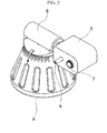
- FIGS. 1 and 2 are perspective views of a conventional three-dimensional radiation detection and visualization system.
- the three-dimensional radiation detection and visualization system illustrated in FIG. 1 is a stereo-type three-dimensional radiation detection and visualization system in which two sensing modules 1 and 2 are applied so as to extract distance information of a radiation source. That is, two two-dimensional images having a disparity are obtained using the two sensing modules 1 and 2, three-dimensional information of a space and a radiation source is calculated from the two two-dimensional images, and thus the distance information of the radiation source may be obtained.
- each of the sensing modules 1 and 2 should have an image sensor configured to obtain image information and a radiation sensor configured to obtain radiation information. Since the sensing modules 1 and 2 are formed of a heavy material for protecting the sensor from radiation, there are limitations in operability and marketability due to a heavy weight.
- the system employs a method realizing a stereo radiation imaging apparatus which includes two motors and one sensing module 5.
- the improved three-dimensional radiation detection and visualization system includes a base part 9, a supporting body 8 coupled to an upper end of the base part 9 to be rotated horizontally, and one sensing module 5 coupled to one side of the supporting body 8 to be rotated vertically.
- the sensing module 5 includes one radiation sensor 6 and one image sensor 7, and scans one of left and right spaces to obtain radiation information and image information. Then the sensing module 5 is rotated at an angle of 180 degrees to scan the other space and thus to obtain the radiation information and the image information.
- FIG. 2 includes one sensing module 5, the system has some advantages in aspects of a cost and a weight, compared with the system of FIG. 1 .
- the radiation sensor 6 and the image sensor 7 are arranged in parallel with each other, and thus center axes thereof do not coincide, a complicated coordinate conversion operation is required in an image overlaying process of the radiation image and the visible light image, and thus there is a high possibility of an error occurring during a three-dimensional visualization process of the radiation information.
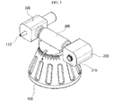
- FIG. 3 is a perspective view of the three-dimensional radiation detection and visualization system according to one embodiment of the present invention
- FIG. 4 is a view for explaining a rotating axis and a center axis of the three-dimensional radiation detection and visualization system according to one embodiment of the present invention.
- the three-dimensional radiation detection and visualization system includes a first sensing module 100, a second sensing module 200, a first supporting body 300 and a second supporting body 400.
- the first sensing module 100 includes one radiation sensor 110
- the second sensing module 200 includes one image sensor 210
- a charge coupled device (CCD) or a complementary metal-oxide semiconductor (CMOS) sensor may be used as the image sensor 210.
- the three-dimensional radiation detection and visualization system includes the two sensing modules 100 and 200, such that the first sensing module 100 includes only the radiation sensor 110 and the second sensing module 200 includes only the image sensor 210.
- the first supporting body 300 is a structure coupled with the first and second sensing modules 100 and 200.
- the first sensing module 100 is coupled to one side of the first supporting body 300
- the second sensing module 200 is coupled to the other side of the first supporting body 300. Therefore, the radiation sensor 110 and the image sensor 210 are independently arranged at left and right sides of the first supporting body and spaced from each other.
- the first and second sensing modules 100 and 200 are coupled so as to be rotated vertically, i.e., to allow tilting rotation.
- the first supporting body 300 have a tilt motor (not shown) which may vertically rotate the first and second sensing modules 100 and 200.
- the first and second sensing modules 100 and 200 have a common rotating axis 310 to be rotated vertically at the same speed. Therefore, the first and second sensing modules 100 and 200 are preferably formed to be rotated at the same time by one tilt motor.
- the second supporting body 400 is coupled with the first supporting body 300. Specifically, the second supporting body 400 is coupled so that the first supporting body 300 may be rotated horizontally.
- the second supporting body 400 has a pan motor which horizontally rotates the first supporting body 300, i.e., allows the first supporting body 300 to perform panning rotation. Therefore, the pan motor horizontally rotates the first supporting body 300 about a rotating axis 410 of the pan motor, and thus the first and second sensing modules 100 and 200 may be horizontally rotated at the same time. Further, the first and second sensing modules 100 and 200 may be formed to be vertically and horizontally rotated at the same time by the tilt motor and the pan motor, and thus the three-dimensional radiation detection and visualization may be performed more rapidly and effectively.
- first radiation information, second radiation information, first image information and second image information may be obtained by the radiation sensor 110 and the image sensor 210 disposed at the first sensing module 100 and the second sensing module 200, respectively.
- the three-dimensional radiation detection and visualization system may further include an information processing part which dimensionalizes visible image-based radiation source detection information based on at least one of the above-mentioned types of information.
- the information processing part may perform at least one of functions of calculating a disparity between the first image information and the second image information; calculating a disparity between the first radiation information and the second radiation information; performing a coordinate calibration of the first radiation information, the second radiation information, the first image information and the second image information; calculating three-dimensional space image information based on the first image information and the second image information; and calculating three-dimensional space radiation information based on the first radiation information and the second radiation information. This will be described in detail later with regard to the three-dimensional radiation detection and visualization method according to another embodiment of the present invention.
- the first and second sensing modules 100 and 200 should be arranged so that a distance a between a center axis C1 of the radiation sensor 110 and the rotating axis 410 of the first supporting body 300 is the same as a distance b between a center axis C2 of the image sensor 210 and the rotating axis 410 of the first supporting body 300. That is, the center axis C1 of the radiation sensor 110 and the center axis C2 of the image sensor 210 are preferably disposed on the vertical rotating axis of the first and second sensing modules 100 and 200.
- the center axis C1 of the radiation sensor 110 and the center axis C2 of the image sensor 210 before the first and second sensing modules 100 and 200 are rotated coincide with the center axes C1 and C2 after the first and second sensing modules 100 and 200 are rotated, and thus matched coordinates may be used when the radiation information and the visible light information are overlaid, and the accurate and simple coordinate conversion may be enabled.
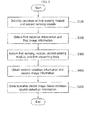
- FIG. 5 is a flowchart time-sequentially illustrating the three-dimensional radiation detection and visualization method according to another embodiment of the present invention
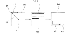
- FIG. 6 is a view illustrating a method in which the radiation sensor 110 scans a target area to obtain the first radiation information in the three-dimensional radiation detection and visualization method according to another embodiment of the present invention
- FIG. 7 is a view illustrating a state in which positions of the first sensing module 100 and the second sensing module 200 are changed by rotation of the first sensing module 100 and the second sensing module 200 in the three-dimensional radiation detection and visualization method according to another embodiment of the present invention
- FIG. 5 is a flowchart time-sequentially illustrating the three-dimensional radiation detection and visualization method according to another embodiment of the present invention
- FIG. 6 is a view illustrating a method in which the radiation sensor 110 scans a target area to obtain the first radiation information in the three-dimensional radiation detection and visualization method according to another embodiment of the present invention
- FIG. 7 is a view illustrating a state in
- FIG. 8 is a view illustrating a method in which the radiation sensor 110 scans the target area to obtain the second radiation information in the three-dimensional radiation detection and visualization method according to another embodiment of the present invention
- FIG. 9 is a flowchart specifically subdividing an operation of dimensionalizing visible image-based radiation source detection information in the three-dimensional radiation detection and visualization method according to another embodiment of the present invention.
- the three-dimensional radiation detection and visualization method is a method using the three-dimensional radiation detection and visualization system according to one embodiment of the present invention.
- the three-dimensional radiation detection and visualization method includes a first operation S100 of initializing positions of the first sensing module 100 and the second sensing module 200, a second operation S200 of obtaining the first radiation information and the first image information, a third operation S300 of rotating the first sensing module 100, the second sensing module 200 and the first supporting body 300, a fourth operation S400 of obtaining the second radiation information and the second image information, and a fifth operation S500 of dimensionalizing the visible image-based radiation source detection information.
- each operation S100 to S500 will be more specifically described.
- the first sensing module 100 and the second sensing module 200 are arranged so that the radiation sensor 110 and the image sensor 210 are directed to a target area 500.
- the first sensing module 100 and the second sensing module 200 are rotated using the tilt motor and the panning motor so that the radiation sensor 110 and the image sensor 210 detect the target area 500.
- the next operation will be described assuming that the first sensing module 100 is arranged at the left side of the first supporting body 300, and the second sensing module 200 is arranged at the right side of the first supporting body 300 in the first operation.
- the image sensor 210 included in the second sensing module 200 takes a picture of the target area 500 and obtains the first image information. Then, the target area 500 is scanned through the radiation sensor 110 included in the first sensing module 100, and thus the first radiation information is obtained. In particular, the radiation information of the target area 500 is obtained while the radiation sensor 110 included in the first sensing module 100 is moved up, down, left and right.
- the target area 500 is scanned while the first sensing module is rotated up and down using the tilt motor, and the first supporting body 300 is rotated horizontally using the pan motor. At this time, an allowable rotation angle is generally set to about +/-20 degrees.
- the center axis C1 of the radiation sensor 110 is moved from an initial set position to a left upper end C3 of the target area 500.
- the tilt motor and the pan motor be driven at the same time so that the center axis C1 of the radiation sensor 110 is moved from the initial set position to the left upper end C3 of the target area 500 through the shortest path L1.
- the radiation sensor 110 starts a scanning process, and as illustrated in FIG. 6 , the target area 500 is scanned along a zigzag path L2, the scanning process is finished after a right lower end C4 of the target area 500 is scanned, and thus the first radiation information is obtained.
- the first sensing module 100 and the second sensing module 200 are vertically rotated at an angle of 180 degrees using the tilt motor, and the first supporting body 300 is horizontally rotated at the angle of 180 degrees using the pan motor.
- the radiation sensor 110 and the image sensor 210 are directed in an opposite direction to the target area 500.
- the radiation sensor 110 and the image sensor 210 are directed to the target area 500.
- the radiation sensor 110 and the image sensor 210 are arranged at the right side and the left side, respectively.
- the horizontal and vertical rotations of the first sensing module 100 and the second sensing module 200 are performed at the same time by the tilt motor and the pan motor, and thus the above-mentioned process is preferably performed at the same time, considering a reduction in a rotating time, as illustrated in FIG. 7 .
- Left and right positions of the radiation sensor 110 and the image sensor 210 are changed by the 180 degree vertical and horizontal movements of the first sensing module 100 and the second sensing module 200. In this case, an imaging surface of the image sensor 210 is reversed up, down, left and right with respect to the initial set position.
- the target area 500 is scanned through the radiation sensor 110 included in the first sensing module 100, and the second radiation information is obtained. Since the position of the radiation sensor 110 is changed from the left side of the horizontal rotating axis to the right side thereof in the third operation S300, the target area of the radiation sensor 110 in the fourth operation S400 does not coincide with that of the radiation sensor 110 in the second operation S200, but coincides with an imaging area of the image sensor 210 in the second operation S200. In particular, the radiation information of the target area 500 is obtained while the first sensing module 100 including the radiation sensor 110 is moved up, down, left and right. The description overlapping that of the second operation S200 will be omitted.
- the fourth operation S400 various examples in which the target area 500 is scanned by the radiation sensor 110 will be described with reference to FIG. 8 .
- a scanning method in which the scanning process is started using a center point C4 after the scanning of the radiation sensor 110 in the second operation S200 as a starting point C5, and the entire target area 500 is scanned through the zigzag path L2 as illustrated in FIG. 8A .
- the scanning process is performed based on position of a radiation area 510 using the radiation image information extracted in the second operation S200, as illustrated in FIGS. 8B and 8C , to minimize a scanning time of the radiation sensor 110.
- FIG. 8B and 8C various examples in which the target area 500 is scanned by the radiation sensor 110 will be described with reference to FIG. 8 .
- the first sensing module 100 may be moved without the scanning process using the tilt motor and the pan motor so that the center axis C1 of the radiation sensor 110 is moved to coordinates C6 adjacent to an edge of the radiation area 510 confirmed in the second operation S200, and the scanning operation may be started along the scanning path L2 of the radiation source from the coordinate C6 adjacent to the edge.
- the center axis C1 of the radiation sensor 110 is moved from the starting point C5 to the coordinate C6 adjacent to the radiation area 510 without the scanning process, as illustrated in FIG.
- the scanning process of the radiation are 510 is briefly performed along a line in an X-axial direction, and thus the scanning time of the radiation sensor 110 may be further reduced.
- the radiation sensor 110 obtains the second radiation information.
- the center axis C1 of the radiation sensor 110 and the center axis C2 of the image sensor 210 are moved to the positions set in the first operation, the picture of the target area 500 is taken using the image sensor 210, and thus the second image information is obtained.
- the imaging area of the image sensor 210 in the fourth operation S400 does not coincide with that of the image sensor 210 in the second operation S200, but coincides with the scanning area of the radiation sensor 110 in the second operation S200.
- the visible image-based radiation detection information is dimensionalized based on the first radiation information, the second radiation information, the first image information and the second image information obtained in the second and fourth operations S200 and S400.
- a 5-1th operation S510 of calculating the disparity between the first image information and the second image information is performed.
- the second image information should be reversed. Then, the disparity between the first radiation information and the second radiation information is calculated.
- the disparities calculated in the 5-1th operation S510, and a 5-2th operation S520 are used as references for obtaining the three-dimensional image and calculating the distance of the radiation source.
- a 5-3th operation S530 of performing the coordinate calibration of the first image information, the second image information, the first radiation information and the second radiation information is performed, and a 5-4th operation S540 of calculating the three-dimensional space image information based on the first image information and the second image information and a 5-5th operation S550 of calculating the three-dimensional space radiation information based on the first radiation information and the second radiation information are performed.
- the three-dimensional space radiation information may be overlaid on the space image information, and thus the position of the radiation source may be visualized in the three-dimensional space.
- the first sensing module including the radiation sensor and the second sensing module including the image sensor are symmetrically arranged, and the pan/tilt motors which rotate the first and second sensing module in the pan/tilt directions are provided, and thus it is possible to minimize the complicated coordinate conversion or the error occurrence during the coordinate conversion.
Landscapes
- Physics & Mathematics (AREA)
- General Physics & Mathematics (AREA)
- Engineering & Computer Science (AREA)
- Molecular Biology (AREA)
- Spectroscopy & Molecular Physics (AREA)
- Health & Medical Sciences (AREA)
- Life Sciences & Earth Sciences (AREA)
- High Energy & Nuclear Physics (AREA)
- Theoretical Computer Science (AREA)
- Computer Vision & Pattern Recognition (AREA)
- Multimedia (AREA)
- Signal Processing (AREA)
- Architecture (AREA)
- Computer Graphics (AREA)
- Computer Hardware Design (AREA)
- General Engineering & Computer Science (AREA)
- Software Systems (AREA)
- Measurement Of Radiation (AREA)
Abstract
Description
- The present invention relates to a three-dimensional radiation detection and visualization system and a method thereof, and more particularly, to a symmetrical-type mono-sensor three-dimensional radiation detection and visualization system which is capable of calculating space radiation information in a three-dimensional space using only one radiation sensor and one image sensor, and a method thereof.
- In an environment in which a radiation leakage accident such as the Chernobyl nuclear accident or the Fukushima nuclear accident has occurred, there are many difficulties due to radiation contamination. Various decontamination techniques are being developed to treat a leakage radiation source or a radiation contamination source, and these techniques are also needed in a decommissioning process of an aging nuclear power plant which is expected to continuously increase in future.
- To decontaminate the radiation contamination source, an operation of finding the contamination source (the radiation source) should be a priority. Today, in developed countries, radiation imaging devices (called "gamma canneras") have been developed and sold at high prices. These devices detect a position of the radiation source using a sensing module (a radiation sensor + an image sensor) coupled with a PMT, a semiconductor sensor or a CCD camera, and overlappingly display the detected position on a real image, thereby contributing greatly to removing the radiation contamination source.
- However, since an apparatus which extracts radiation information using a conventional radiation imaging device and images (visualizes) the extracted information by overlaying a radiation image on a real image (a visible light image) has one sensing module, and thus can provide only direction information of the radiation source, and cannot obtain distance information to the radiation source, there is a problem in that it is not possible to know a distance to the radiation source and an intensity of the radiation source.
- To solve this problem, an apparatus which extracts the distance information to the radiation source using stereo-type apparatus having two sensing modules is being developed. However, since the apparatus has a high manufacturing cost and a heavy weight, there are limitations in operability and marketability.
- The present invention is directed to a three-dimensional radiation detection and visualization system capable of minimizing a complicated coordinate conversion process or error occurrence during the coordinate conversion process which constitutes a problem in an existing stereo radiation imaging device realizing three-dimensional radiation detection and visualization by using two radiation sensing modules or moving a position of one sensing module, and a method thereof.
- According to an aspect of the present invention, there is provided a three-dimensional radiation detection and visualization system including a first sensing module including one radiation sensor, a second sensing module including one image sensor, a first supporting body in which the first sensing module and the second sensing module are coupled to one side and the other side thereof to be vertically rotated, and a second supporting body coupled with the first supporting body so that the first supporting body is horizontally rotated.
- According to another aspect of the present invention, there is provided a three-dimensional radiation detection and visualization system using a three-dimensional radiation detection and visualization system including a first sensing module including one radiation sensor, a second sensing module including one image sensor, a first supporting body in which the first sensing module and the second sensing module are coupled to one side and the other side thereof to be vertically rotated, and a second supporting body coupled with the first supporting body so that the first supporting body is horizontally rotated, the method including a first operation of arranging the first sensing module and the second sensing module so that the radiation sensor and the image sensor are directed to a target area, a second operation in which the radiation sensor obtains first radiation information of the target area, and the image sensor obtains first image information of the target area, a third operation of vertically rotating the first sensing module and the second sensing module at an angle of 180 degrees, and horizontally rotating the first supporting body at the angle of 180 degrees, and a fourth operation in which the radiation sensor obtains second radiation information of the target area, and the image sensor obtains second image information of the target area.
- The above and other objects, features and advantages of the present invention will become more apparent to those of ordinary skill in the art by describing in detail exemplary embodiments thereof with reference to the accompanying drawings, in which:
-
FIGS. 1 and2 are perspective views of a conventional three-dimensional radiation detection and visualization system. -
FIG. 3 is a perspective view of a three-dimensional radiation detection and visualization system according to one embodiment of the present invention; -
FIG. 4 is a view for explaining a rotating axis and a center axis of the three-dimensional radiation detection and visualization system according to one embodiment of the present invention; -
FIG. 5 is a flowchart time-sequentially illustrating a three-dimensional radiation detection and visualization method according to another embodiment of the present invention; -
FIG. 6 is a view illustrating a method in which a radiation sensor scans a target area to obtain first radiation information in the three-dimensional radiation detection and visualization method according to another embodiment of the present invention; -
FIG. 7 is a view illustrating a state in which positions of a first sensing module and a second sensing module are changed by rotation of the first sensing module and the second sensing module in the three-dimensional radiation detection and visualization method according to another embodiment of the present invention; -
FIG. 8 is a view illustrating a method in which the radiation sensor scans the target area to obtain second radiation information in the three-dimensional radiation detection and visualization method according to another embodiment of the present invention; and -
FIG. 9 is a flowchart specifically subdividing an operation of dimensionalizing radiation source detection information based on a visible image in the three-dimensional radiation detection and visualization method according to another embodiment of the present invention. -
100: first sensing module 110: radiation sensor 200: second sensing module 210: image sensor 300: first supporting body 400: second supporting body 500: target area - Exemplary embodiments of the present invention will be described in detail below with reference to the accompanying drawings, wherein like reference numerals refer to like or corresponding elements throughout the drawings and repeated description thereof will be omitted.
- Further, in the following description, if it is considered that the specific description of the related and noticed functions or structures may obscure the gist of the present invention, the specific description will be omitted. Also, the accompanying drawings are used to help easily understand the technical idea of the present invention and it should be understood that the idea of the present invention is not limited by the accompanying drawings.
- Hereinafter, a conventional three-dimensional radiation detection and visualization system will be briefly described with reference to
FIGS. 1 and2 .FIGS. 1 and2 are perspective views of a conventional three-dimensional radiation detection and visualization system. - The three-dimensional radiation detection and visualization system illustrated in
FIG. 1 is a stereo-type three-dimensional radiation detection and visualization system in which twosensing modules 1 and 2 are applied so as to extract distance information of a radiation source. That is, two two-dimensional images having a disparity are obtained using the twosensing modules 1 and 2, three-dimensional information of a space and a radiation source is calculated from the two two-dimensional images, and thus the distance information of the radiation source may be obtained. However, each of thesensing modules 1 and 2 should have an image sensor configured to obtain image information and a radiation sensor configured to obtain radiation information. Since thesensing modules 1 and 2 are formed of a heavy material for protecting the sensor from radiation, there are limitations in operability and marketability due to a heavy weight. - To solve this problem, there has been an attempt to realize a stereo-type structure using one sensing module. As an example thereof, there was proposed a method in which a space contaminated by radiation is scanned by one sensing module located at a left (or right) side, and the sensing module is moved to a right (or left) side, and then the space is scanned once again, and thus functions of two left and right sensing modules are realized by one sensing module. However, since an additional structure for moving the sensing module is required, there is another problem in that it is difficult to solve the problem of the heavy weight of the three-dimensional radiation detection and visualization system.
- To solve this problem, a system as illustrated in
FIG. 2 has been proposed. Specifically, the system employs a method realizing a stereo radiation imaging apparatus which includes two motors and onesensing module 5. As illustrated inFIG. 2 , the improved three-dimensional radiation detection and visualization system includes abase part 9, a supportingbody 8 coupled to an upper end of thebase part 9 to be rotated horizontally, and onesensing module 5 coupled to one side of the supportingbody 8 to be rotated vertically. Thesensing module 5 includes oneradiation sensor 6 and oneimage sensor 7, and scans one of left and right spaces to obtain radiation information and image information. Then thesensing module 5 is rotated at an angle of 180 degrees to scan the other space and thus to obtain the radiation information and the image information. An image processing process with respect to each of the obtained images is performed, and three-dimensional radiation information may be finally obtained. Since the system ofFIG. 2 includes onesensing module 5, the system has some advantages in aspects of a cost and a weight, compared with the system ofFIG. 1 . However, since theradiation sensor 6 and theimage sensor 7 are arranged in parallel with each other, and thus center axes thereof do not coincide, a complicated coordinate conversion operation is required in an image overlaying process of the radiation image and the visible light image, and thus there is a high possibility of an error occurring during a three-dimensional visualization process of the radiation information. - A three-dimensional radiation detection and visualization system according to one embodiment of the present invention and a three-dimensional radiation detection and visualization method according to another embodiment of the present invention are provided to solve the problems in the stereo-type three-dimensional radiation detection and visualization system illustrated in
FIGS. 1 and2 . First, the three-dimensional radiation detection and visualization system according to one embodiment of the present invention will be described with reference toFIGS. 3 and4 .FIG. 3 is a perspective view of the three-dimensional radiation detection and visualization system according to one embodiment of the present invention, andFIG. 4 is a view for explaining a rotating axis and a center axis of the three-dimensional radiation detection and visualization system according to one embodiment of the present invention. - As illustrated in
FIG. 3 , the three-dimensional radiation detection and visualization system according to one embodiment of the present invention includes afirst sensing module 100, asecond sensing module 200, a first supportingbody 300 and a second supportingbody 400. Thefirst sensing module 100 includes oneradiation sensor 110, thesecond sensing module 200 includes oneimage sensor 210, and a charge coupled device (CCD) or a complementary metal-oxide semiconductor (CMOS) sensor may be used as theimage sensor 210. Unlike the system ofFIGS. 1 and2 , the three-dimensional radiation detection and visualization system according to one embodiment of the present invention includes the twosensing modules first sensing module 100 includes only theradiation sensor 110 and thesecond sensing module 200 includes only theimage sensor 210. - The first supporting
body 300 is a structure coupled with the first andsecond sensing modules first sensing module 100 is coupled to one side of the first supportingbody 300, and thesecond sensing module 200 is coupled to the other side of the first supportingbody 300. Therefore, theradiation sensor 110 and theimage sensor 210 are independently arranged at left and right sides of the first supporting body and spaced from each other. In particular, the first andsecond sensing modules body 300 have a tilt motor (not shown) which may vertically rotate the first andsecond sensing modules FIG. 4 , the first andsecond sensing modules axis 310 to be rotated vertically at the same speed. Therefore, the first andsecond sensing modules - The second supporting
body 400 is coupled with the first supportingbody 300. Specifically, the second supportingbody 400 is coupled so that the first supportingbody 300 may be rotated horizontally. The second supportingbody 400 has a pan motor which horizontally rotates the first supportingbody 300, i.e., allows the first supportingbody 300 to perform panning rotation. Therefore, the pan motor horizontally rotates the first supportingbody 300 about arotating axis 410 of the pan motor, and thus the first andsecond sensing modules second sensing modules - Meanwhile, first radiation information, second radiation information, first image information and second image information, which will be described later, may be obtained by the
radiation sensor 110 and theimage sensor 210 disposed at thefirst sensing module 100 and thesecond sensing module 200, respectively. The three-dimensional radiation detection and visualization system according to one embodiment of the present invention may further include an information processing part which dimensionalizes visible image-based radiation source detection information based on at least one of the above-mentioned types of information. The information processing part may perform at least one of functions of calculating a disparity between the first image information and the second image information; calculating a disparity between the first radiation information and the second radiation information; performing a coordinate calibration of the first radiation information, the second radiation information, the first image information and the second image information; calculating three-dimensional space image information based on the first image information and the second image information; and calculating three-dimensional space radiation information based on the first radiation information and the second radiation information. This will be described in detail later with regard to the three-dimensional radiation detection and visualization method according to another embodiment of the present invention. - Meanwhile, arrangement of the first and
second sensing modules FIG. 4 . As illustrated inFIG. 4 , the first andsecond sensing modules radiation sensor 110 and therotating axis 410 of the first supportingbody 300 is the same as a distance b between a center axis C2 of theimage sensor 210 and therotating axis 410 of the first supportingbody 300. That is, the center axis C1 of theradiation sensor 110 and the center axis C2 of theimage sensor 210 are preferably disposed on the vertical rotating axis of the first andsecond sensing modules radiation sensor 110 and the center axis C2 of theimage sensor 210 before the first andsecond sensing modules second sensing modules - Hereinafter, the three-dimensional radiation detection and visualization method according to another embodiment of the present invention will be specifically described with reference to
FIGS. 5 to 9 .FIG. 5 is a flowchart time-sequentially illustrating the three-dimensional radiation detection and visualization method according to another embodiment of the present invention,FIG. 6 is a view illustrating a method in which theradiation sensor 110 scans a target area to obtain the first radiation information in the three-dimensional radiation detection and visualization method according to another embodiment of the present invention,FIG. 7 is a view illustrating a state in which positions of thefirst sensing module 100 and thesecond sensing module 200 are changed by rotation of thefirst sensing module 100 and thesecond sensing module 200 in the three-dimensional radiation detection and visualization method according to another embodiment of the present invention,FIG. 8 is a view illustrating a method in which theradiation sensor 110 scans the target area to obtain the second radiation information in the three-dimensional radiation detection and visualization method according to another embodiment of the present invention, andFIG. 9 is a flowchart specifically subdividing an operation of dimensionalizing visible image-based radiation source detection information in the three-dimensional radiation detection and visualization method according to another embodiment of the present invention. - The three-dimensional radiation detection and visualization method according to another embodiment of the present invention is a method using the three-dimensional radiation detection and visualization system according to one embodiment of the present invention. As illustrated in
FIG. 5 , the three-dimensional radiation detection and visualization method according to another embodiment of the present invention includes a first operation S100 of initializing positions of thefirst sensing module 100 and thesecond sensing module 200, a second operation S200 of obtaining the first radiation information and the first image information, a third operation S300 of rotating thefirst sensing module 100, thesecond sensing module 200 and the first supportingbody 300, a fourth operation S400 of obtaining the second radiation information and the second image information, and a fifth operation S500 of dimensionalizing the visible image-based radiation source detection information. Hereinafter, each operation S100 to S500 will be more specifically described. - In the first operation S100, the
first sensing module 100 and thesecond sensing module 200 are arranged so that theradiation sensor 110 and theimage sensor 210 are directed to atarget area 500. Preferably, thefirst sensing module 100 and thesecond sensing module 200 are rotated using the tilt motor and the panning motor so that theradiation sensor 110 and theimage sensor 210 detect thetarget area 500. The next operation will be described assuming that thefirst sensing module 100 is arranged at the left side of the first supportingbody 300, and thesecond sensing module 200 is arranged at the right side of the first supportingbody 300 in the first operation. - In the second operation S200, first, the
image sensor 210 included in thesecond sensing module 200 takes a picture of thetarget area 500 and obtains the first image information. Then, thetarget area 500 is scanned through theradiation sensor 110 included in thefirst sensing module 100, and thus the first radiation information is obtained. In particular, the radiation information of thetarget area 500 is obtained while theradiation sensor 110 included in thefirst sensing module 100 is moved up, down, left and right. Here, thetarget area 500 is scanned while the first sensing module is rotated up and down using the tilt motor, and the first supportingbody 300 is rotated horizontally using the pan motor. At this time, an allowable rotation angle is generally set to about +/-20 degrees. An example in which thetarget area 500 is scanned by theradiation sensor 110 will be specifically described with reference toFIG. 6 . First, the center axis C1 of theradiation sensor 110 is moved from an initial set position to a left upper end C3 of thetarget area 500. At this time, as illustrated inFIG. 6 , it is preferable that the tilt motor and the pan motor be driven at the same time so that the center axis C1 of theradiation sensor 110 is moved from the initial set position to the left upper end C3 of thetarget area 500 through the shortest path L1. Then, theradiation sensor 110 starts a scanning process, and as illustrated inFIG. 6 , thetarget area 500 is scanned along a zigzag path L2, the scanning process is finished after a right lower end C4 of thetarget area 500 is scanned, and thus the first radiation information is obtained. - In the third operation S300, the
first sensing module 100 and thesecond sensing module 200 are vertically rotated at an angle of 180 degrees using the tilt motor, and the first supportingbody 300 is horizontally rotated at the angle of 180 degrees using the pan motor. Specifically, when thefirst sensing module 100 and thesecond sensing module 200 are rotated at the angle of 180 degrees, theradiation sensor 110 and theimage sensor 210 are directed in an opposite direction to thetarget area 500. In this state, when the first supportingbody 300 is rotated at the angle of 180 degrees, theradiation sensor 110 and theimage sensor 210 are directed to thetarget area 500. However, unlike the initial set position, theradiation sensor 110 and theimage sensor 210 are arranged at the right side and the left side, respectively. The horizontal and vertical rotations of thefirst sensing module 100 and thesecond sensing module 200 are performed at the same time by the tilt motor and the pan motor, and thus the above-mentioned process is preferably performed at the same time, considering a reduction in a rotating time, as illustrated inFIG. 7 . Left and right positions of theradiation sensor 110 and theimage sensor 210 are changed by the 180 degree vertical and horizontal movements of thefirst sensing module 100 and thesecond sensing module 200. In this case, an imaging surface of theimage sensor 210 is reversed up, down, left and right with respect to the initial set position. - In the fourth operation S400, the
target area 500 is scanned through theradiation sensor 110 included in thefirst sensing module 100, and the second radiation information is obtained. Since the position of theradiation sensor 110 is changed from the left side of the horizontal rotating axis to the right side thereof in the third operation S300, the target area of theradiation sensor 110 in the fourth operation S400 does not coincide with that of theradiation sensor 110 in the second operation S200, but coincides with an imaging area of theimage sensor 210 in the second operation S200. In particular, the radiation information of thetarget area 500 is obtained while thefirst sensing module 100 including theradiation sensor 110 is moved up, down, left and right. The description overlapping that of the second operation S200 will be omitted. In particular, in the fourth operation S400, various examples in which thetarget area 500 is scanned by theradiation sensor 110 will be described with reference toFIG. 8 . First, there is a scanning method in which the scanning process is started using a center point C4 after the scanning of theradiation sensor 110 in the second operation S200 as a starting point C5, and theentire target area 500 is scanned through the zigzag path L2 as illustrated inFIG. 8A . Further, there is another scanning method in which the scanning process is performed based on position of aradiation area 510 using the radiation image information extracted in the second operation S200, as illustrated inFIGS. 8B and 8C , to minimize a scanning time of theradiation sensor 110. Specifically, as illustrated inFIG. 8B , thefirst sensing module 100 may be moved without the scanning process using the tilt motor and the pan motor so that the center axis C1 of theradiation sensor 110 is moved to coordinates C6 adjacent to an edge of theradiation area 510 confirmed in the second operation S200, and the scanning operation may be started along the scanning path L2 of the radiation source from the coordinate C6 adjacent to the edge. In addition, when the radiation image information extracted in the second operation S200 is confirmed and it is determined that the radiation is small, the center axis C1 of theradiation sensor 110 is moved from the starting point C5 to the coordinate C6 adjacent to theradiation area 510 without the scanning process, as illustrated inFIG. 8C , and then the scanning process of the radiation are 510 is briefly performed along a line in an X-axial direction, and thus the scanning time of theradiation sensor 110 may be further reduced. Through the above-mentioned processes, theradiation sensor 110 obtains the second radiation information. Then, the center axis C1 of theradiation sensor 110 and the center axis C2 of theimage sensor 210 are moved to the positions set in the first operation, the picture of thetarget area 500 is taken using theimage sensor 210, and thus the second image information is obtained. Since the position of theimage sensor 210 is changed from the right side of the horizontal axis to the left side thereof by performing the third operation S300, the imaging area of theimage sensor 210 in the fourth operation S400 does not coincide with that of theimage sensor 210 in the second operation S200, but coincides with the scanning area of theradiation sensor 110 in the second operation S200. - In the fifth area S500, the visible image-based radiation detection information is dimensionalized based on the first radiation information, the second radiation information, the first image information and the second image information obtained in the second and fourth operations S200 and S400. When the fifth operation is further subdivided, a 5-1th operation S510 of calculating the disparity between the first image information and the second image information is performed. At this time, as described above, since the first image information and the second image information are reversed up, down, left and right, the second image information should be reversed. Then, the disparity between the first radiation information and the second radiation information is calculated. The disparities calculated in the 5-1th operation S510, and a 5-2th operation S520 are used as references for obtaining the three-dimensional image and calculating the distance of the radiation source. A 5-3th operation S530 of performing the coordinate calibration of the first image information, the second image information, the first radiation information and the second radiation information is performed, and a 5-4th operation S540 of calculating the three-dimensional space image information based on the first image information and the second image information and a 5-5th operation S550 of calculating the three-dimensional space radiation information based on the first radiation information and the second radiation information are performed. After the above-mentioned operations, the three-dimensional space radiation information may be overlaid on the space image information, and thus the position of the radiation source may be visualized in the three-dimensional space.
- In the three-dimensional radiation detection and visualization system according to one embodiment of the present invention and the three-dimensional radiation detection and visualization method according to another embodiment of the present invention, the first sensing module including the radiation sensor and the second sensing module including the image sensor are symmetrically arranged, and the pan/tilt motors which rotate the first and second sensing module in the pan/tilt directions are provided, and thus it is possible to minimize the complicated coordinate conversion or the error occurrence during the coordinate conversion.
- Also, since it is not necessary to provide two sensing modules having the radiation sensor and the image sensor, a producing cost can be reduced, and also a small size and a light weight can be achieved.
- It will be apparent to those skilled in the art that various modifications can be made to the above-described exemplary embodiments of the present invention without departing from the spirit or scope of the invention. Thus, it is intended that the present invention cover all such modifications provided they come within the scope of the appended claims.
Claims (15)
- A three-dimensional radiation detection and visualization system comprising:a first sensing module (100) including one radiation sensor (110);a second sensing module (200) including one image sensor (210);a first supporting body (300) in which the first sensing module (100) and the second sensing module (200) are coupled to one side and the other side thereof to be vertically rotated; anda second supporting body (400) coupled with the first supporting body (300) so that the first supporting body (300) is horizontally rotated.
- The system of claim 1, further comprising a tilt motor configured to vertically rotate the first sensing module (100) and the second sensing module (200); and a pan motor configured to horizontally rotate the first supporting body (300).
- The system of claim 2, wherein the tilt motor rotates the first sensing module (100) and the second sensing module (200) at the same time.
- The system of claim 2, wherein vertical rotations of the first sensing module (100) and the second sensing module (200) by the tilt motor and horizontal rotation of the first supporting body (300) by the pan motor are performed at the same time.
- The system of claim 1, wherein, while the first sensing module (100) and the second sensing module (200) are arranged so that the radiation sensor (110) and the image sensor (210) are directed to a target area, the radiation sensor and the image sensor obtain first radiation information and first image information of the target area, respectively, and
the first sensing module (100) and the second sensing module (200) are vertically rotated at an angle of 180 degrees, the first supporting body (300) is horizontally rotated at the angle of 180 degrees, and then the radiation sensor (110) and the image sensor (210) obtain second radiation information and second image information of the target area, respectively. - The system of claim 5, wherein the radiation sensor (110) obtains at least one of the first radiation information and the second radiation information by rotating the first sensing module (100) vertically and the first supporting body (300) horizontally within a predetermined angular range and scanning the target area.
- The system of claim 5, further comprising an information processing part configured to dimensionalize visible image-based radiation source detection information based on at least one of the first radiation information, the second radiation information, the first image information and the second image information.
- The system of claim 7, wherein the information processing part performs at least one of functions of calculating a disparity between the first image information and the second image information; calculating a disparity between the first radiation information and the second radiation information; performing a coordinate calibration of the first radiation information, the second radiation information, the first image information and the second image information; calculating three-dimensional space image information based on the first image information and the second image information; and calculating three-dimensional space radiation information based on the first radiation information and the second radiation information.
- The system of claim 1, wherein a distance between a center axis (C1) of the radiation sensor (110) and a rotating axis of the first supporting body is the same as a distance between a center axis of the image sensor and the rotating axis of the first supporting body (300).
- A three-dimensional radiation detection and visualization method using a three-dimensional radiation detection and visualization system comprising a first sensing module (100) including one radiation sensor (110), a second sensing module (200) including one image sensor (210), a first supporting body (300) in which the first sensing module (100) and the second sensing module (200) are coupled to one side and the other side thereof to be vertically rotated, and a second supporting body (400) coupled with the first supporting body (300) so that the first supporting body (300) is horizontally rotated, the method comprising:a first operation (S100) of arranging the first sensing module (100) and the second sensing module (2009 so that the radiation sensor (110) and the image sensor (210) are directed to a target area;a second operation (S200) in which the radiation sensor (110) obtains first radiation information of the target area, and the image sensor (210) obtains first image information of the target area;a third operation (S300) of vertically rotating the first sensing module (100) and the second sensing module (200) at an angle of 180 degrees, and horizontally rotating the first supporting body (300) at the angle of 180 degrees; anda fourth operation (S400) in which the radiation sensor (110) obtains second radiation information of the target area, and the image sensor (210) obtains second image information of the target area.
- The method of claim 10, wherein, in the second operation (S200), the radiation sensor (110) obtains the first radiation information by rotating the first sensing module (100) vertically and the first supporting body (300) horizontally within a predetermined angular range and scanning the target area.
- The method of claim 10, wherein, in the third operation (S300), vertical rotations of the first sensing module (100) and the second sensing module (200) and horizontal rotation of the first supporting body (300) are performed at the same time.
- The method of claim 10, wherein, in the fourth operation (S400), the radiation sensor (110) obtains the second radiation information by rotating the first sensing module (100) vertically and the first supporting body (300) horizontally within a predetermined angular range and scanning the target area.
- The method of claim 10, further comprising a fifth operation (S500) of dimensionalizing visible image-based radiation source detection information based on the first radiation information, the second radiation information, the first image information and the second image information.
- The method of claim 10, wherein the fifth operation (S500) comprises a 5-1th operation of calculating the disparity between the first image information and the second image information; a 5-2th operation of calculating the disparity between the first radiation information and the second radiation information; a 5-3th operation of performing a coordinate calibration of the first image information, the second image information, the first radiation information and the second radiation information; a 5-4th operation of calculating three-dimensional space image information based on the first image information and the second image information; and a 5-5th operation of calculating three-dimensional space radiation information based on the first radiation information and the second radiation information.
Applications Claiming Priority (1)
| Application Number | Priority Date | Filing Date | Title |
|---|---|---|---|
| KR1020140087658A KR101681130B1 (en) | 2014-07-11 | 2014-07-11 | Symmetrical-type mono-sensor three-dimensional radiation detection and visualization system and method thereof |
Publications (2)
| Publication Number | Publication Date |
|---|---|
| EP2966478A1 true EP2966478A1 (en) | 2016-01-13 |
| EP2966478B1 EP2966478B1 (en) | 2019-12-18 |
Family
ID=52444225
Family Applications (1)
| Application Number | Title | Priority Date | Filing Date |
|---|---|---|---|
| EP15153966.5A Active EP2966478B1 (en) | 2014-07-11 | 2015-02-05 | Symmetrical-type mono-sensor three-dimensional radiation detection and visualisation system and method thereof |
Country Status (4)
| Country | Link |
|---|---|
| US (1) | US9910164B2 (en) |
| EP (1) | EP2966478B1 (en) |
| JP (1) | JP6095236B2 (en) |
| KR (1) | KR101681130B1 (en) |
Cited By (1)
| Publication number | Priority date | Publication date | Assignee | Title |
|---|---|---|---|---|
| WO2018146358A1 (en) | 2017-02-10 | 2018-08-16 | Consejo Superior De Investigaciones Cientificas (Csic) | System and metod for the volumetric and isotopic identification of radiation distribution in radioactive surroundings |
Families Citing this family (7)
| Publication number | Priority date | Publication date | Assignee | Title |
|---|---|---|---|---|
| JP6309831B2 (en) * | 2014-06-10 | 2018-04-11 | 株式会社東芝 | Wireless device |
| KR101868043B1 (en) * | 2016-12-02 | 2018-06-19 | 경북대학교 산학협력단 | Apparatus and method for detecting 3-dimension position of radiation source |
| KR102736305B1 (en) * | 2022-04-29 | 2024-11-29 | 한국수력원자력 주식회사 | Apparatus of alignment for Radiation detector |
| CN114720915B (en) * | 2022-06-08 | 2022-09-02 | 苏州佳祺仕信息科技有限公司 | Calibration method and device for three-dimensional Hall probe and visual guidance system |
| KR102539500B1 (en) * | 2022-10-21 | 2023-06-05 | (주)에스에프테크놀로지 | One-shot hybrid CBRN integrated remote detection device and method consisting of harmful gas detection and radiation detection in one device |
| KR102859985B1 (en) * | 2023-05-04 | 2025-09-15 | 한국원자력연구원 | Device for visualtizing radioactive contamination information using omni-directional radiation detection and metheod thereof |
| KR102951443B1 (en) | 2023-10-31 | 2026-04-10 | 한국원자력연구원 | Device for detecting direction of omni-directional radiation based on mobile platform-mounted sensor and metheod thereof |
Citations (4)
| Publication number | Priority date | Publication date | Assignee | Title |
|---|---|---|---|---|
| JPS60227186A (en) * | 1984-04-25 | 1985-11-12 | Fuji Electric Co Ltd | Radiation television set |
| US5204533A (en) * | 1989-10-11 | 1993-04-20 | Genevieve Simonet | Device for localizing radiation sources in real time |
| US6380541B1 (en) * | 1997-10-15 | 2002-04-30 | Commissariat A L'energie Atomique | Device for locating radiation sources |
| KR101309826B1 (en) * | 2012-09-26 | 2013-10-14 | 한국수력원자력 주식회사 | A remote-controllable stereo-type hybrid radiation and visible imaging equipment |
Family Cites Families (19)
| Publication number | Priority date | Publication date | Assignee | Title |
|---|---|---|---|---|
| JPH0627819B2 (en) * | 1989-10-25 | 1994-04-13 | 関西電力株式会社 | Method and device for measuring distribution of radiation dose rate |
| JP2815774B2 (en) * | 1993-04-16 | 1998-10-27 | 富士電機株式会社 | Scanning mechanism of radiation television equipment |
| FR2759791B1 (en) * | 1997-02-17 | 1999-04-09 | Cogema | RADIATION SOURCE MAPPING DEVICE |
| US7466843B2 (en) * | 2000-07-07 | 2008-12-16 | Pryor Timothy R | Multi-functional control and entertainment systems |
| US20110102553A1 (en) * | 2007-02-28 | 2011-05-05 | Tessera Technologies Ireland Limited | Enhanced real-time face models from stereo imaging |
| KR100806072B1 (en) * | 2006-04-10 | 2008-02-21 | 한국원자력연구원 | Radiation source 3D position detection method and apparatus using two CD cameras |
| KR100897154B1 (en) * | 2007-04-25 | 2009-05-14 | 성균관대학교산학협력단 | Gamma rays and optical dual imaging equipment |
| DE102008003816B4 (en) * | 2008-01-10 | 2013-08-01 | Siemens Aktiengesellschaft | X-ray device comprising a preferably rotatably mounted on a robot arm C-arm |
| JP2009210429A (en) * | 2008-03-04 | 2009-09-17 | Nihon Medi Physics Co Ltd | Tester and angle adjustment apparatus |
| GB0817487D0 (en) * | 2008-09-24 | 2008-10-29 | Durham Scient Crystals Ltd | Radiographic data interpretation |
| US20120212499A1 (en) * | 2010-02-28 | 2012-08-23 | Osterhout Group, Inc. | System and method for display content control during glasses movement |
| EP2622608A2 (en) * | 2010-08-18 | 2013-08-07 | Savannah River Nuclear Solutions, LLC | System and method for the identification of radiation in contaminated rooms |
| KR101275212B1 (en) * | 2010-10-15 | 2013-06-14 | 한국표준과학연구원 | Apparatus and Method for Detection of Radiation |
| CA2814242C (en) * | 2010-10-15 | 2020-01-07 | Atomic Energy Of Canada Limited | Directional radiation detection apparatus and method using inverse collimation |
| KR20120097833A (en) | 2011-02-25 | 2012-09-05 | 삼성테크윈 주식회사 | Guard and surveillance robot |
| JP5774451B2 (en) * | 2011-11-18 | 2015-09-09 | 株式会社東芝 | Radioactivity three-dimensional measuring device, radiation handling work management system, and radiation handling work management method |
| US9116249B1 (en) * | 2012-07-26 | 2015-08-25 | Sandia Corporation | Multiple-mode radiation detector |
| JP5918093B2 (en) * | 2012-09-21 | 2016-05-18 | 日立アロカメディカル株式会社 | Radiation measurement apparatus and radiation measurement method |
| JP3181739U (en) * | 2012-12-03 | 2013-02-21 | いであ株式会社 | Towed underwater radioactivity measurement system |
-
2014
- 2014-07-11 KR KR1020140087658A patent/KR101681130B1/en active Active
-
2015
- 2015-01-20 JP JP2015008624A patent/JP6095236B2/en not_active Expired - Fee Related
- 2015-02-05 EP EP15153966.5A patent/EP2966478B1/en active Active
- 2015-04-27 US US14/697,198 patent/US9910164B2/en not_active Expired - Fee Related
Patent Citations (4)
| Publication number | Priority date | Publication date | Assignee | Title |
|---|---|---|---|---|
| JPS60227186A (en) * | 1984-04-25 | 1985-11-12 | Fuji Electric Co Ltd | Radiation television set |
| US5204533A (en) * | 1989-10-11 | 1993-04-20 | Genevieve Simonet | Device for localizing radiation sources in real time |
| US6380541B1 (en) * | 1997-10-15 | 2002-04-30 | Commissariat A L'energie Atomique | Device for locating radiation sources |
| KR101309826B1 (en) * | 2012-09-26 | 2013-10-14 | 한국수력원자력 주식회사 | A remote-controllable stereo-type hybrid radiation and visible imaging equipment |
Cited By (2)
| Publication number | Priority date | Publication date | Assignee | Title |
|---|---|---|---|---|
| WO2018146358A1 (en) | 2017-02-10 | 2018-08-16 | Consejo Superior De Investigaciones Cientificas (Csic) | System and metod for the volumetric and isotopic identification of radiation distribution in radioactive surroundings |
| US11022705B2 (en) | 2017-02-10 | 2021-06-01 | Consejo Superior De Investigaciones Cientificas (Csic) | System and method for the volumetric and isotopic identification of radiation distribution in radioactive surroundings |
Also Published As
| Publication number | Publication date |
|---|---|
| JP2016020889A (en) | 2016-02-04 |
| KR101681130B1 (en) | 2016-12-12 |
| JP6095236B2 (en) | 2017-03-15 |
| US20160011322A1 (en) | 2016-01-14 |
| KR20160007253A (en) | 2016-01-20 |
| US9910164B2 (en) | 2018-03-06 |
| EP2966478B1 (en) | 2019-12-18 |
Similar Documents
| Publication | Publication Date | Title |
|---|---|---|
| EP2966478B1 (en) | Symmetrical-type mono-sensor three-dimensional radiation detection and visualisation system and method thereof | |
| AU2024203568A1 (en) | Methods and systems for imaging a scene, such as a medical scene, and tracking objects within the scene | |
| CN102792334B (en) | Video generation device and operations support systems | |
| JP5465128B2 (en) | Point cloud position data processing device, point cloud position data processing system, point cloud position data processing method, and point cloud position data processing program | |
| CN110809786B (en) | Calibration device, calibration chart, chart pattern generating device and calibration method | |
| CN104006825B (en) | Systems and methods for calibrating machine vision cameras along at least three discrete planes | |
| EP3359043B1 (en) | X-ray imaging apparatus, control method for the same, and x-ray detector | |
| JP5966341B2 (en) | Image processing apparatus, image processing method, program for image processing apparatus, and image display apparatus | |
| US20120293633A1 (en) | Stereo camera | |
| US20110063417A1 (en) | System and method for automatic calibration of stereo images | |
| JP6615545B2 (en) | Image processing apparatus, image processing method, and image processing program | |
| TWI521471B (en) | 3 - dimensional distance measuring device and method thereof | |
| CN113841384A (en) | Calibration devices, charts and calibration methods for calibration | |
| Strelow et al. | Precise omnidirectional camera calibration | |
| JP6177006B2 (en) | Camera calibration apparatus and camera calibration method | |
| CN115797467B (en) | Vehicle camera calibration result detection method, device, equipment and storage medium | |
| KR101721683B1 (en) | Vertical-type mono-sensor three-dimensional radiation detection and visualization system and method thereof | |
| JP6854472B2 (en) | Imaging device and imaging method | |
| KR102484103B1 (en) | Display system | |
| KR101553598B1 (en) | Apparatus and method for formating 3d image with stereo vision | |
| KR101609188B1 (en) | Depth camera system of optimal arrangement to improve the field of view | |
| JP2011087319A (en) | In-vehicle panorama camera system | |
| WO2015159791A1 (en) | Distance measuring device and distance measuring method | |
| JP2005205519A (en) | Robot hand device | |
| JP6579706B2 (en) | Image processing apparatus, image processing method, and image processing program |
Legal Events
| Date | Code | Title | Description |
|---|---|---|---|
| PUAI | Public reference made under article 153(3) epc to a published international application that has entered the european phase |
Free format text: ORIGINAL CODE: 0009012 |
|
| 17P | Request for examination filed |
Effective date: 20150209 |
|
| AK | Designated contracting states |
Kind code of ref document: A1 Designated state(s): AL AT BE BG CH CY CZ DE DK EE ES FI FR GB GR HR HU IE IS IT LI LT LU LV MC MK MT NL NO PL PT RO RS SE SI SK SM TR |
|
| AX | Request for extension of the european patent |
Extension state: BA ME |
|
| RIN1 | Information on inventor provided before grant (corrected) |
Inventor name: LEE, NAM-HO Inventor name: HWANG, YOUNG GWAN Inventor name: PARK, SOON-YONG Inventor name: JUNG, HYUN-KYU Inventor name: KIM, JONG YEOL |
|
| GRAP | Despatch of communication of intention to grant a patent |
Free format text: ORIGINAL CODE: EPIDOSNIGR1 |
|
| STAA | Information on the status of an ep patent application or granted ep patent |
Free format text: STATUS: GRANT OF PATENT IS INTENDED |
|
| INTG | Intention to grant announced |
Effective date: 20190708 |
|
| GRAS | Grant fee paid |
Free format text: ORIGINAL CODE: EPIDOSNIGR3 |
|
| GRAA | (expected) grant |
Free format text: ORIGINAL CODE: 0009210 |
|
| STAA | Information on the status of an ep patent application or granted ep patent |
Free format text: STATUS: THE PATENT HAS BEEN GRANTED |
|
| AK | Designated contracting states |
Kind code of ref document: B1 Designated state(s): AL AT BE BG CH CY CZ DE DK EE ES FI FR GB GR HR HU IE IS IT LI LT LU LV MC MK MT NL NO PL PT RO RS SE SI SK SM TR |
|
| REG | Reference to a national code |
Ref country code: CH Ref legal event code: EP |
|
| REG | Reference to a national code |
Ref country code: DE Ref legal event code: R096 Ref document number: 602015043701 Country of ref document: DE |
|
| REG | Reference to a national code |
Ref country code: IE Ref legal event code: FG4D |
|
| REG | Reference to a national code |
Ref country code: AT Ref legal event code: REF Ref document number: 1215246 Country of ref document: AT Kind code of ref document: T Effective date: 20200115 |
|
| REG | Reference to a national code |
Ref country code: NL Ref legal event code: MP Effective date: 20191218 |
|
| PG25 | Lapsed in a contracting state [announced via postgrant information from national office to epo] |
Ref country code: LT Free format text: LAPSE BECAUSE OF FAILURE TO SUBMIT A TRANSLATION OF THE DESCRIPTION OR TO PAY THE FEE WITHIN THE PRESCRIBED TIME-LIMIT Effective date: 20191218 Ref country code: NO Free format text: LAPSE BECAUSE OF FAILURE TO SUBMIT A TRANSLATION OF THE DESCRIPTION OR TO PAY THE FEE WITHIN THE PRESCRIBED TIME-LIMIT Effective date: 20200318 Ref country code: GR Free format text: LAPSE BECAUSE OF FAILURE TO SUBMIT A TRANSLATION OF THE DESCRIPTION OR TO PAY THE FEE WITHIN THE PRESCRIBED TIME-LIMIT Effective date: 20200319 Ref country code: BG Free format text: LAPSE BECAUSE OF FAILURE TO SUBMIT A TRANSLATION OF THE DESCRIPTION OR TO PAY THE FEE WITHIN THE PRESCRIBED TIME-LIMIT Effective date: 20200318 Ref country code: FI Free format text: LAPSE BECAUSE OF FAILURE TO SUBMIT A TRANSLATION OF THE DESCRIPTION OR TO PAY THE FEE WITHIN THE PRESCRIBED TIME-LIMIT Effective date: 20191218 Ref country code: SE Free format text: LAPSE BECAUSE OF FAILURE TO SUBMIT A TRANSLATION OF THE DESCRIPTION OR TO PAY THE FEE WITHIN THE PRESCRIBED TIME-LIMIT Effective date: 20191218 Ref country code: LV Free format text: LAPSE BECAUSE OF FAILURE TO SUBMIT A TRANSLATION OF THE DESCRIPTION OR TO PAY THE FEE WITHIN THE PRESCRIBED TIME-LIMIT Effective date: 20191218 |
|
| REG | Reference to a national code |
Ref country code: LT Ref legal event code: MG4D |
|
| PG25 | Lapsed in a contracting state [announced via postgrant information from national office to epo] |
Ref country code: RS Free format text: LAPSE BECAUSE OF FAILURE TO SUBMIT A TRANSLATION OF THE DESCRIPTION OR TO PAY THE FEE WITHIN THE PRESCRIBED TIME-LIMIT Effective date: 20191218 Ref country code: HR Free format text: LAPSE BECAUSE OF FAILURE TO SUBMIT A TRANSLATION OF THE DESCRIPTION OR TO PAY THE FEE WITHIN THE PRESCRIBED TIME-LIMIT Effective date: 20191218 |
|
| PG25 | Lapsed in a contracting state [announced via postgrant information from national office to epo] |
Ref country code: AL Free format text: LAPSE BECAUSE OF FAILURE TO SUBMIT A TRANSLATION OF THE DESCRIPTION OR TO PAY THE FEE WITHIN THE PRESCRIBED TIME-LIMIT Effective date: 20191218 |
|
| PG25 | Lapsed in a contracting state [announced via postgrant information from national office to epo] |
Ref country code: RO Free format text: LAPSE BECAUSE OF FAILURE TO SUBMIT A TRANSLATION OF THE DESCRIPTION OR TO PAY THE FEE WITHIN THE PRESCRIBED TIME-LIMIT Effective date: 20191218 Ref country code: CZ Free format text: LAPSE BECAUSE OF FAILURE TO SUBMIT A TRANSLATION OF THE DESCRIPTION OR TO PAY THE FEE WITHIN THE PRESCRIBED TIME-LIMIT Effective date: 20191218 Ref country code: NL Free format text: LAPSE BECAUSE OF FAILURE TO SUBMIT A TRANSLATION OF THE DESCRIPTION OR TO PAY THE FEE WITHIN THE PRESCRIBED TIME-LIMIT Effective date: 20191218 Ref country code: EE Free format text: LAPSE BECAUSE OF FAILURE TO SUBMIT A TRANSLATION OF THE DESCRIPTION OR TO PAY THE FEE WITHIN THE PRESCRIBED TIME-LIMIT Effective date: 20191218 Ref country code: PT Free format text: LAPSE BECAUSE OF FAILURE TO SUBMIT A TRANSLATION OF THE DESCRIPTION OR TO PAY THE FEE WITHIN THE PRESCRIBED TIME-LIMIT Effective date: 20200513 |
|
| PG25 | Lapsed in a contracting state [announced via postgrant information from national office to epo] |
Ref country code: SK Free format text: LAPSE BECAUSE OF FAILURE TO SUBMIT A TRANSLATION OF THE DESCRIPTION OR TO PAY THE FEE WITHIN THE PRESCRIBED TIME-LIMIT Effective date: 20191218 Ref country code: SM Free format text: LAPSE BECAUSE OF FAILURE TO SUBMIT A TRANSLATION OF THE DESCRIPTION OR TO PAY THE FEE WITHIN THE PRESCRIBED TIME-LIMIT Effective date: 20191218 Ref country code: IS Free format text: LAPSE BECAUSE OF FAILURE TO SUBMIT A TRANSLATION OF THE DESCRIPTION OR TO PAY THE FEE WITHIN THE PRESCRIBED TIME-LIMIT Effective date: 20200418 |
|
| REG | Reference to a national code |
Ref country code: DE Ref legal event code: R119 Ref document number: 602015043701 Country of ref document: DE |
|
| REG | Reference to a national code |
Ref country code: CH Ref legal event code: PL |
|
| REG | Reference to a national code |
Ref country code: AT Ref legal event code: MK05 Ref document number: 1215246 Country of ref document: AT Kind code of ref document: T Effective date: 20191218 |
|
| PLBE | No opposition filed within time limit |
Free format text: ORIGINAL CODE: 0009261 |
|
| STAA | Information on the status of an ep patent application or granted ep patent |
Free format text: STATUS: NO OPPOSITION FILED WITHIN TIME LIMIT |
|
| REG | Reference to a national code |
Ref country code: BE Ref legal event code: MM Effective date: 20200229 |
|
| PG25 | Lapsed in a contracting state [announced via postgrant information from national office to epo] |
Ref country code: DK Free format text: LAPSE BECAUSE OF FAILURE TO SUBMIT A TRANSLATION OF THE DESCRIPTION OR TO PAY THE FEE WITHIN THE PRESCRIBED TIME-LIMIT Effective date: 20191218 Ref country code: ES Free format text: LAPSE BECAUSE OF FAILURE TO SUBMIT A TRANSLATION OF THE DESCRIPTION OR TO PAY THE FEE WITHIN THE PRESCRIBED TIME-LIMIT Effective date: 20191218 Ref country code: LU Free format text: LAPSE BECAUSE OF NON-PAYMENT OF DUE FEES Effective date: 20200205 Ref country code: MC Free format text: LAPSE BECAUSE OF FAILURE TO SUBMIT A TRANSLATION OF THE DESCRIPTION OR TO PAY THE FEE WITHIN THE PRESCRIBED TIME-LIMIT Effective date: 20191218 |
|
| 26N | No opposition filed |
Effective date: 20200921 |
|
| PG25 | Lapsed in a contracting state [announced via postgrant information from national office to epo] |
Ref country code: LI Free format text: LAPSE BECAUSE OF NON-PAYMENT OF DUE FEES Effective date: 20200229 Ref country code: AT Free format text: LAPSE BECAUSE OF FAILURE TO SUBMIT A TRANSLATION OF THE DESCRIPTION OR TO PAY THE FEE WITHIN THE PRESCRIBED TIME-LIMIT Effective date: 20191218 Ref country code: CH Free format text: LAPSE BECAUSE OF NON-PAYMENT OF DUE FEES Effective date: 20200229 Ref country code: SI Free format text: LAPSE BECAUSE OF FAILURE TO SUBMIT A TRANSLATION OF THE DESCRIPTION OR TO PAY THE FEE WITHIN THE PRESCRIBED TIME-LIMIT Effective date: 20191218 |
|
| PG25 | Lapsed in a contracting state [announced via postgrant information from national office to epo] |
Ref country code: DE Free format text: LAPSE BECAUSE OF NON-PAYMENT OF DUE FEES Effective date: 20200901 Ref country code: IT Free format text: LAPSE BECAUSE OF FAILURE TO SUBMIT A TRANSLATION OF THE DESCRIPTION OR TO PAY THE FEE WITHIN THE PRESCRIBED TIME-LIMIT Effective date: 20191218 Ref country code: IE Free format text: LAPSE BECAUSE OF NON-PAYMENT OF DUE FEES Effective date: 20200205 |
|
| PG25 | Lapsed in a contracting state [announced via postgrant information from national office to epo] |
Ref country code: BE Free format text: LAPSE BECAUSE OF NON-PAYMENT OF DUE FEES Effective date: 20200229 Ref country code: PL Free format text: LAPSE BECAUSE OF FAILURE TO SUBMIT A TRANSLATION OF THE DESCRIPTION OR TO PAY THE FEE WITHIN THE PRESCRIBED TIME-LIMIT Effective date: 20191218 |
|
| PG25 | Lapsed in a contracting state [announced via postgrant information from national office to epo] |
Ref country code: TR Free format text: LAPSE BECAUSE OF FAILURE TO SUBMIT A TRANSLATION OF THE DESCRIPTION OR TO PAY THE FEE WITHIN THE PRESCRIBED TIME-LIMIT Effective date: 20191218 Ref country code: MT Free format text: LAPSE BECAUSE OF FAILURE TO SUBMIT A TRANSLATION OF THE DESCRIPTION OR TO PAY THE FEE WITHIN THE PRESCRIBED TIME-LIMIT Effective date: 20191218 Ref country code: CY Free format text: LAPSE BECAUSE OF FAILURE TO SUBMIT A TRANSLATION OF THE DESCRIPTION OR TO PAY THE FEE WITHIN THE PRESCRIBED TIME-LIMIT Effective date: 20191218 |
|
| PG25 | Lapsed in a contracting state [announced via postgrant information from national office to epo] |
Ref country code: MK Free format text: LAPSE BECAUSE OF FAILURE TO SUBMIT A TRANSLATION OF THE DESCRIPTION OR TO PAY THE FEE WITHIN THE PRESCRIBED TIME-LIMIT Effective date: 20191218 |
|
| PGFP | Annual fee paid to national office [announced via postgrant information from national office to epo] |
Ref country code: GB Payment date: 20231220 Year of fee payment: 10 |
|
| PGFP | Annual fee paid to national office [announced via postgrant information from national office to epo] |
Ref country code: FR Payment date: 20231222 Year of fee payment: 10 |
|
| GBPC | Gb: european patent ceased through non-payment of renewal fee |
Effective date: 20250205 |
|
| PG25 | Lapsed in a contracting state [announced via postgrant information from national office to epo] |
Ref country code: GB Free format text: LAPSE BECAUSE OF NON-PAYMENT OF DUE FEES Effective date: 20250205 |
|
| PG25 | Lapsed in a contracting state [announced via postgrant information from national office to epo] |
Ref country code: FR Free format text: LAPSE BECAUSE OF NON-PAYMENT OF DUE FEES Effective date: 20250228 |