EP2966350A1 - Axial swirler - Google Patents
Axial swirler Download PDFInfo
- Publication number
- EP2966350A1 EP2966350A1 EP14176546.1A EP14176546A EP2966350A1 EP 2966350 A1 EP2966350 A1 EP 2966350A1 EP 14176546 A EP14176546 A EP 14176546A EP 2966350 A1 EP2966350 A1 EP 2966350A1
- Authority
- EP
- European Patent Office
- Prior art keywords
- swirler
- function
- radial distance
- axis
- burner
- Prior art date
- Legal status (The legal status is an assumption and is not a legal conclusion. Google has not performed a legal analysis and makes no representation as to the accuracy of the status listed.)
- Granted
Links
Images




Classifications
-
- F—MECHANICAL ENGINEERING; LIGHTING; HEATING; WEAPONS; BLASTING
- F23—COMBUSTION APPARATUS; COMBUSTION PROCESSES
- F23D—BURNERS
- F23D14/00—Burners for combustion of a gas, e.g. of a gas stored under pressure as a liquid
- F23D14/02—Premix gas burners, i.e. in which gaseous fuel is mixed with combustion air upstream of the combustion zone
-
- F—MECHANICAL ENGINEERING; LIGHTING; HEATING; WEAPONS; BLASTING
- F23—COMBUSTION APPARATUS; COMBUSTION PROCESSES
- F23D—BURNERS
- F23D14/00—Burners for combustion of a gas, e.g. of a gas stored under pressure as a liquid
- F23D14/20—Non-premix gas burners, i.e. in which gaseous fuel is mixed with combustion air on arrival at the combustion zone
- F23D14/22—Non-premix gas burners, i.e. in which gaseous fuel is mixed with combustion air on arrival at the combustion zone with separate air and gas feed ducts, e.g. with ducts running parallel or crossing each other
- F23D14/24—Non-premix gas burners, i.e. in which gaseous fuel is mixed with combustion air on arrival at the combustion zone with separate air and gas feed ducts, e.g. with ducts running parallel or crossing each other at least one of the fluids being submitted to a swirling motion
-
- F—MECHANICAL ENGINEERING; LIGHTING; HEATING; WEAPONS; BLASTING
- F23—COMBUSTION APPARATUS; COMBUSTION PROCESSES
- F23R—GENERATING COMBUSTION PRODUCTS OF HIGH PRESSURE OR HIGH VELOCITY, e.g. GAS-TURBINE COMBUSTION CHAMBERS
- F23R3/00—Continuous combustion chambers using liquid or gaseous fuel
- F23R3/02—Continuous combustion chambers using liquid or gaseous fuel characterised by the air-flow or gas-flow configuration
- F23R3/04—Air inlet arrangements
- F23R3/10—Air inlet arrangements for primary air
- F23R3/12—Air inlet arrangements for primary air inducing a vortex
- F23R3/14—Air inlet arrangements for primary air inducing a vortex by using swirl vanes
-
- F—MECHANICAL ENGINEERING; LIGHTING; HEATING; WEAPONS; BLASTING
- F23—COMBUSTION APPARATUS; COMBUSTION PROCESSES
- F23C—METHODS OR APPARATUS FOR COMBUSTION USING FLUID FUEL OR SOLID FUEL SUSPENDED IN A CARRIER GAS OR AIR
- F23C2900/00—Special features of, or arrangements for combustion apparatus using fluid fuels or solid fuels suspended in air; Combustion processes therefor
- F23C2900/07001—Air swirling vanes incorporating fuel injectors
Definitions
- the present invention relates to an axial swirler, in particular for premixing purposes in gas turbines, and it relates further to a burner for a combustion chamber with such an axial swirler.
- axial swirlers for the introduction of at least one gaseous and/or liquid into a burner.
- Swirlers are used as mixing devices in various technical applications. Optimization of swirlers aims at reducing the energy required to obtain a specified degree of homogeneity of a mixture. In continuous flow mixing the pressure drop over a mixing device is a measure for the required energy. Further, the time and space required to obtain the specified degree of homogeneity are important parameters for the evaluation of mixing devices or mixing elements. Swirlers are typically used for mixing of two or more continuous fluid streams. Axial swirlers are most commonly used as premixers in gas turbine combustors. A so-called swirl number s n characterizes the swirl strength of an axial swirler. The swirl number is defined as the ratio between the axial flux of azimuthal momentum and the axial flux of axial momentum multiplied by the swirler radius. The swirl number is an indication of the intensity of swirl in the annular flow induced by the swirler.
- Swirl burners are devices that, by imparting sufficiently strong swirl to an air flow, lead to the formation of a central reverse flow region (CRZ) due to the vortex breakdown mechanism which can be used for the stabilization of flames in gas turbine combustors.
- CRZ central reverse flow region
- a burner comprising such a swirler is disclosed.
- an axial swirler for a gas turbine burner comprising a plurality of swirl vanes with a streamline cross-section being arranged around a swirler axis and extending in radial direction between an inner radius (R min ) and an outer radius (R max ).
- the minimum radial distance R min is the distance from the swirler axis to the inner side or the inner lateral surface of the swirl vane.
- the maximum radial distance R max is the distance from the swirler axis to the outer side or the outer lateral surface of the swirl vane.
- Each swirl vane has a leading edge, a trailing edge, and a suction side and a pressure side extending each between said leading and trailing edges.
- Discharge flow angle ( ⁇ ) between a tangent to the swirl vane camber line at its trailing edge and the swirler axis is first function of radial distance (R) from the swirler axis
- a position of maximum camber of the swirl vane is second function of radial distance (R) from the swirler axis.
- said first and second functions comprise each a respective local maximum and local minimum values along said radial distance from R min to R max .
- said first function of radial distance (R) from the swirler axis, and/or said second function of radial distance (R) from the swirler axis are periodic functions.
- a period of the said first function of radial distance (R) from the swirler axis, or/and said second function of radial distance (R) from the swirler axis is from 1 to 100 mm, preferably in the range 20-60 mm.
- said first function of radial distance (R) from the swirler axis, and/or said second function of radial distance (R) from the swirler axis are sinusoidal functions.
- said first function of radial distance (R) from the swirler axis, and/or said second function of radial distance (R) from the swirler axis are triangular or rectangular functions.
- said first function of radial distance (R) from the swirler axis, and/or said second function of radial distance (R) from the swirler axis are the same function type.
- they can both be sinusoidal.
- said first function of radial distance (R) from the swirler axis, and said second function of radial distance (R) from the swirler axis are substantially in phase along radial distance from R min to R max .
- the first periodic function of radial distance (R) from the swirler axis is given by a function: ⁇ 0 + R b ⁇ ⁇ * sin 2 ⁇ ⁇ NR where ⁇ 0 is fixed angle, ⁇ * is maximum angle deviation, b and N are rational numbers.
- all the swirl vanes are identically formed and/or all the swirl vanes are arranged around the swirler axis in a circle.
- the said first function of radial distance (R) from the swirler axis of two adjacent vanes are in phase or are out of phase inverted.
- the swirler as described above leads to a good mixing at low pressure drop but also to a high recirculation flow in a subsequent combustor.
- the burner comprising an axial swirler as described above is characterized in that at least one of the swirl vanes is configured as an injection device with at least one fuel nozzle for introducing at least one fuel into the burner.
- the burner can comprise one swirler or a plurality of swirlers.
- a burner with one swirler typically has a circular cross section.
- a burner comprising a plurality of swirlers can have any cross-section but is typically circular or rectangular.
- a plurality of burners is arranged coaxially around the axis of a gas turbine.
- the burner cross-section is defined by a limiting wall, which for example forms a can-like burner.
- the burner under full load injects fuel from the suction side or the pressure side of at least one, preferable of all swirl vanes.
- the fuel is injected on the suction side and the pressure side of each swirler vane, i.e. from both sides of the injecting swirl vane simultaneously.
- the axial swirler and/or the burner described above is used in an annular combustor, a can combustors, or a single or reheat engines.
- FIG 1 shows a schematic perspective view onto a conventional swirler 43.
- the swirler 43 comprises an annular housing with an inner limiting wall 44', an outer limiting wall 44'', an inlet area 45, and an outlet area 46.
- Vanes 3 are arranged between the inner limiting wall 44' and outer limiting wall 44''.
- the swirl vanes 3 are provided with a discharge flow angle that does not depend on a distance R from a swirl axis 47, but is constant throughout the annulus.
- the leading edge area of each vane 3 has a profile, which is oriented parallel to the inlet flow direction 48.
- the vanes are extending in radial direction between an inner radius (R min ) and an outer radius (R max ).
- the inflow is coaxial to the longitudinal axis 47 of the swirler 43.
- the profiles of the vanes 3 turn from the main flow direction 48 to impose a swirl on the flow, and resulting in an outlet-flow direction 55, which has an angle relative to the inlet flow direction 48.
- the main flow is coaxial to the annular swirler.
- the outlet flow is rotating around the axis 47 of the swirler 43.
- the swirler blade 3 is characterized by a cross section at radius R defined by a given distribution of the camber line and of the blade thickness, for example, as given by NACA type airfoils as shown in Figure 2 .
- Swirl vane 3 has a leading edge 25, a trailing edge 24, and a suction side 22 and a pressure side 23 extending each between said leading and trailing edges (25, 24).
- the swirler blades are obtained requiring that the radial distribution of the tangent to the airfoil camber line at the trailing edge and the swirler axis is equal to the target exit flow angle distribution ⁇ (R).
- the axial lobed swirler is usually obtained by superimposing a periodic deviation in the exit flow angle to the main one characterizing the standard axial swirler.
- the swirler map corresponding to this design is shown in Figure 6 .
- ⁇ R R b ⁇ ⁇ * ⁇ sin 2 ⁇ ⁇ ⁇ N lobes R where ⁇ * is the maximum deviation, N lobes the number of lobes and where linear dependency from R b is introduced to modulate the maximum deviation from the minimum to the maximum radiuses. Value of b between 0.3 and 3 are considered.
- the design criteria given in the previous section for the lobed axial swirler implies a periodic fluctuation of the azimuthal drop ⁇ of the trailing edge.
- the design according to the embodiments of the invention, proposed here, consists in avoiding this fluctuation of the trailing edge by compensating with a fluctuation in the position of maximum camber C.
- the airfoils at three different radial locations for a) standard, b) lobed and c) swirler according to the invention are shown in Figure 11 .
- the figure shows the monotonic azimuthal displacement of the trailing edge, in case of standard and swirler according to the invention (as expected in case of a straight trailing edge) and the non-monotonic displacement in case of lobed swirler.
- the variation of angle ⁇ is however monotonic only in case of standard swirler, as required by the target distribution.
- Figure 12 shows the complete airfoils at the three different radial locations.
- the figure shows that the position of maximum camber is approximately constant and equal to 0.4 in case of the standard and lobed swirlers while it moves non-monotonically in case of the swirler according to the invention.
- This characteristic for the axial swirler according to the invention is shown in details in figure 11 .
- the first derivative of function at local maximum or minimum is zero.
- the burner comprising an axial swirler as described above is characterized in that at least one of the swirl vanes is configured as an injection device with at least one fuel nozzle for introducing at least one fuel into the burner.
- the burner can comprise one swirler or a plurality of swirlers.
- a burner with one swirler typically has a circular cross section.
- a burner comprising a plurality of swirlers can have any cross-section but is typically circular or rectangular.
- a plurality of burners is arranged coaxially around the axis of a gas turbine.
- the burner cross-section is defined by a limiting wall, which for example forms a can-like burner.
- the burner under full load injects fuel from the suction side or the pressure side of at least one, preferable of all swirl vanes.
- the fuel is injected on the suction side and the pressure side of each swirler vane, i.e. from both sides of the injecting swirl vane simultaneously.
- Figure 14 shows according to the embodiments of the invention: a) an example of an annular combustor with burners comprising one swirler per burner as well as in b) an example of an annular combustor with burners comprising five swirlers per burner.
- Figure 15 shows injection of fuel from suction and pressure side of the swirler blade according to one embodiment of the invention.
Landscapes
- Engineering & Computer Science (AREA)
- Chemical & Material Sciences (AREA)
- Combustion & Propulsion (AREA)
- Mechanical Engineering (AREA)
- General Engineering & Computer Science (AREA)
- Turbine Rotor Nozzle Sealing (AREA)
- Cyclones (AREA)
- Air Supply (AREA)
Description
- The present invention relates to an axial swirler, in particular for premixing purposes in gas turbines, and it relates further to a burner for a combustion chamber with such an axial swirler. In particular it relates to axial swirlers for the introduction of at least one gaseous and/or liquid into a burner.
- Swirlers are used as mixing devices in various technical applications. Optimization of swirlers aims at reducing the energy required to obtain a specified degree of homogeneity of a mixture. In continuous flow mixing the pressure drop over a mixing device is a measure for the required energy. Further, the time and space required to obtain the specified degree of homogeneity are important parameters for the evaluation of mixing devices or mixing elements. Swirlers are typically used for mixing of two or more continuous fluid streams. Axial swirlers are most commonly used as premixers in gas turbine combustors. A so-called swirl number sn characterizes the swirl strength of an axial swirler. The swirl number is defined as the ratio between the axial flux of azimuthal momentum and the axial flux of axial momentum multiplied by the swirler radius. The swirl number is an indication of the intensity of swirl in the annular flow induced by the swirler.
- Swirl burners are devices that, by imparting sufficiently strong swirl to an air flow, lead to the formation of a central reverse flow region (CRZ) due to the vortex breakdown mechanism which can be used for the stabilization of flames in gas turbine combustors.
- Targeting best fuel-air premixing and low pressure drop is often a challenge for this kind of devices. Good fuel-air premixing must be in fact achieved in a mixing region before the CRZ where the flame is stabilized. This implies the need in this mixing region of sufficiently high pressure losses, i.e. the use of a swirler with sufficiently high swirl number which allows the tangential shearing necessary to well premix fuel with air. High swirl number flows however give also origin to strong shearing at CRZ with too large and unnecessary pressure losses just in this region.
- An improvement to the standard design of axial swirl burner has been proposed in
US 2012/0285173 . This improvement consists in the introduction of a lobed trailing edge which can create small scale counter-rotating vortices embedded into the main vortex and able to enhance fuel-air mixing without significant effect on the swirl number of the main vortex. This solution, which has its origin in the application of lobes to non-swirling devices (disclosed inEP 2 522 912 - The use of these existing design concepts (standard and lobed swirlers) carries however several risks and disadvantages. In case of the lobed axial swirler, the main risk is flow separation at the trailing edge due to change in the exit flow angle taking place too late along the chord of the swirler. A second deficiency is given by the formation of rotating secondary flow structures in the swirler vanes which, carrying the fuel around, make rather challenging the control and optimization of fuel spatial distribution (spatial un-mixedness). In addition, the strong distortion along the trailing edge given by the lobed structure represents, on its own, a major manufacturing difficulty.
- For all these reasons, there is a need for the new swirlers that could allow reduced pressure drop, robust flashback characteristics and improved NOx (due to better mixing), but also keep design relatively simple.
- It is an object of the present invention to provide a highly effective swirler with a low pressure drop. As an application of such a swirler a burner comprising such a swirler is disclosed.
- The above and other objects are achieved by an axial swirler for a gas turbine burner, comprising a plurality of swirl vanes with a streamline cross-section being arranged around a swirler axis and extending in radial direction between an inner radius (Rmin) and an outer radius (Rmax). The minimum radial distance Rmin is the distance from the swirler axis to the inner side or the inner lateral surface of the swirl vane. The maximum radial distance Rmax is the distance from the swirler axis to the outer side or the outer lateral surface of the swirl vane. Each swirl vane has a leading edge, a trailing edge, and a suction side and a pressure side extending each between said leading and trailing edges. Discharge flow angle (α) between a tangent to the swirl vane camber line at its trailing edge and the swirler axis is first function of radial distance (R) from the swirler axis , and a position of maximum camber of the swirl vane is second function of radial distance (R) from the swirler axis. At least for one swirl vane said first and second functions comprise each a respective local maximum and local minimum values along said radial distance from Rmin to Rmax.
- According to one embodiment, said first function of radial distance (R) from the swirler axis, and/or said second function of radial distance (R) from the swirler axis are periodic functions. A period of the said first function of radial distance (R) from the swirler axis, or/and said second function of radial distance (R) from the swirler axis is from 1 to 100 mm, preferably in the range 20-60 mm. According to one embodiment, said first function of radial distance (R) from the swirler axis, and/or said second function of radial distance (R) from the swirler axis are sinusoidal functions.
- According to another embodiment, said first function of radial distance (R) from the swirler axis, and/or said second function of radial distance (R) from the swirler axis are triangular or rectangular functions.
- According to one embodiment, said first function of radial distance (R) from the swirler axis, and/or said second function of radial distance (R) from the swirler axis are the same function type. For example, they can both be sinusoidal.
- According to yet another embodiment said first function of radial distance (R) from the swirler axis, and said second function of radial distance (R) from the swirler axis are substantially in phase along radial distance from Rmin to Rmax.
- According to one embodiment, the first periodic function of radial distance (R) from the swirler axis is given by a function:

where α0 is fixed angle, α* is maximum angle deviation, b and N are rational numbers. - According to another embodiment all the swirl vanes are identically formed and/or all the swirl vanes are arranged around the swirler axis in a circle.
- According to yet another embodiment, the said first function of radial distance (R) from the swirler axis of two adjacent vanes are in phase or are out of phase inverted.
- If applied to a burner, the swirler as described above leads to a good mixing at low pressure drop but also to a high recirculation flow in a subsequent combustor.
- The burner comprising an axial swirler as described above is characterized in that at least one of the swirl vanes is configured as an injection device with at least one fuel nozzle for introducing at least one fuel into the burner. The burner can comprise one swirler or a plurality of swirlers. A burner with one swirler typically has a circular cross section. A burner comprising a plurality of swirlers can have any cross-section but is typically circular or rectangular. Typically a plurality of burners is arranged coaxially around the axis of a gas turbine. The burner cross-section is defined by a limiting wall, which for example forms a can-like burner.
- In one embodiment the burner under full load injects fuel from the suction side or the pressure side of at least one, preferable of all swirl vanes.
- In a particularly preferred embodiment, the fuel is injected on the suction side and the pressure side of each swirler vane, i.e. from both sides of the injecting swirl vane simultaneously.
- Preferably the axial swirler and/or the burner described above is used in an annular combustor, a can combustors, or a single or reheat engines.
- Further embodiments of the invention are laid down in the dependent claims.
- Preferred embodiments of the invention are described in the following with reference to the drawings, which are for the purpose of illustrating the present preferred embodiments of the invention and not for the purpose of limiting the same. In the drawings,
-
Figure 1 shows a schematic perspective view onto a conventional swirler with swirl vanes having trailing edges with conventional discharge flow angles α(R) = const.; -
Figure 2 shows cross section of swirler blade based on NACA4 airfoil; -
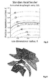
Figure 3 shows distribution of Ω/L for a standard axial swirler with αMIN = 20°, αMAX = 50°; -
Figure 4 shows schematic perspective view of eight blades standard axial swirler corresponding to L = 1.4, Ω=45°; -
Figure 5 shows radial distributions of exit flow angle of standard swirler corresponding toFigure 3 and Figure 4 ; -
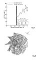
Figure 6 shows distribution of Ω/L for a lobed axial swirler; -
Figure 7 shows radial distributions of the exit flow angle for standard and lobed swirler. The exit flow angle is given in table for three values of the radius; -
Figure 8 shows schematic perspective view of lobed swirler according to prior art -
Figure 9 shows distribution of Ω/L for an axial swirler according to embodiment of the invention; -
Figure 10 shows schematic perspective view of an axial swirler according to embodiment of the invention; -
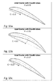
Figure 11 shows trailing edge at three different values of the radius and exit flow angle for a) standard, b) lobed and c) swirler according to the invention; -
Figure 12 shows complete airfoils in case of the three types of swirler: a) standard, b) lobed and c) swirler according to the invention, for three different radial sections; -
Figure 13 shows, for the swirler according to the invention, the non-monotonic change of maximum camber position for increasing radius necessary to keep the trailing edge along s straight line; -
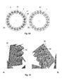
Figure 14 shows according to the embodiments of the invention: a) an example of an annular combustor with burners comprising one swirler per burner as well as in b) an example of an annular combustor with a burners comprising five swirlers per burner; -
Figure 15 shows injection of fuel from a) suction and b) pressure side of the swirler blade according to one embodiment of the invention. -
Figure 1 shows a schematic perspective view onto aconventional swirler 43. Theswirler 43 comprises an annular housing with an inner limiting wall 44', an outer limiting wall 44'', aninlet area 45, and anoutlet area 46.Vanes 3 are arranged between the inner limiting wall 44' and outer limiting wall 44''. Theswirl vanes 3 are provided with a discharge flow angle that does not depend on a distance R from aswirl axis 47, but is constant throughout the annulus. The leading edge area of eachvane 3 has a profile, which is oriented parallel to theinlet flow direction 48. The vanes are extending in radial direction between an inner radius (Rmin) and an outer radius (Rmax). In the example shown the inflow is coaxial to thelongitudinal axis 47 of theswirler 43. The profiles of thevanes 3 turn from themain flow direction 48 to impose a swirl on the flow, and resulting in an outlet-flow direction 55, which has an angle relative to theinlet flow direction 48. The main flow is coaxial to the annular swirler. The outlet flow is rotating around theaxis 47 of theswirler 43. - For better understanding and appreciation of the embodiments of the present invention, first, design of standard and lobed axial swirler from prior art will be explained.
- We refer to a class of swirlers with exit flow angle (α) whose tangent is linearly increasing in radial direction from a minimum value αMIN at the minimum radius Rmin to a maximum value αMAX at the maximum radius RMAX. The radius is normalized with its maximum value, hence RMAX=1:

- The
swirler blade 3 is characterized by a cross section at radius R defined by a given distribution of the camber line and of the blade thickness, for example, as given by NACA type airfoils as shown inFigure 2 .Swirl vane 3 has aleading edge 25, a trailingedge 24, and asuction side 22 and apressure side 23 extending each between said leading and trailing edges (25, 24). The swirler blades are obtained requiring that the radial distribution of the tangent to the airfoil camber line at the trailing edge and the swirler axis is equal to the target exit flow angle distribution α(R). - An additional condition is given by the tangent to the camber line at the leading edge aligned with the swirler axis. These two conditions determine a one-to-one relation between the distribution of Ω/L, the ratio between the azimuthal drop Ω from leading to trailing edge in a cylindrical coordinate system and swirler blade axial extension L, and the position of the maximum camber C at any given radius R.
-
Figure 3 shows the distribution of this ratio for a swirler with αMIN=20°, αMAX=50° in terms of radius R and position of maximum camber C. Any path from R=Rmin to R= Rmax represents a swirler blade nominally delivering the target exit flow distribution. A swirler for example with L = cost = 1.4 and Ω = 45° is obtained taking the radial distribution of, almost constant and equal to 0.4, as given by the black line. - This swirler is shown on the
Figure 4 , while exit flow angle as a function of non-dimensional radius R is shown inFigure 5 . - The axial lobed swirler is usually obtained by superimposing a periodic deviation in the exit flow angle to the main one characterizing the standard axial swirler. The swirler map corresponding to this design is shown in
Figure 6 . - The deviation that is used here is given by:

- The design of such a swirler is achieved, by introducing this fluctuation more or less gradually along the airfoils (sometimes suddenly) starting from the position of the maximum camber of the standard axial swirler. Such a design concept leads to a swirler with a periodically lobed trailing edge as shown in
Figure 8 for a case with b=1 and α= 10°. Exit flow angle as a function of non-dimensional radius R for lobed swirler is shown inFig 7 . - The design criteria given in the previous section for the lobed axial swirler implies a periodic fluctuation of the azimuthal drop Ω of the trailing edge. The design according to the embodiments of the invention, proposed here, consists in avoiding this fluctuation of the trailing edge by compensating with a fluctuation in the position of maximum camber C.
- The necessary distribution of the position of the maximum camber C which gives a straight trailing edge is shown from the swirler map of
Fig 9 . This is the thick dashed line of Ω / L = 32° (Figure 9 ) which implies a periodic fluctuation in position of maximum camber C, counterbalancing the lobed shape of the trailing edge. The axial swirler obtained by the selection of this maximum camber line distribution is shown inFigure 10 . This swirler displays a trailing edge which is straight and has the same discharge flow characteristics of the lobed axial swirler. - In order to have a more clear explanation, the airfoils at three different radial locations for a) standard, b) lobed and c) swirler according to the invention are shown in
Figure 11 . The figure shows the monotonic azimuthal displacement of the trailing edge, in case of standard and swirler according to the invention (as expected in case of a straight trailing edge) and the non-monotonic displacement in case of lobed swirler. The variation of angle α is however monotonic only in case of standard swirler, as required by the target distribution. -
Figure 12 shows the complete airfoils at the three different radial locations. The figure shows that the position of maximum camber is approximately constant and equal to 0.4 in case of the standard and lobed swirlers while it moves non-monotonically in case of the swirler according to the invention. This characteristic for the axial swirler according to the invention is shown in details infigure 11 . - Above described embodiment shows an example where a discharge flow angle α between a tangent 26 to the swirl
vane camber line 27 at its trailingedge 24 and theswirler axis 47 is sinusoidal function of a radial distance R from theswirler axis 47, and a position ofmaximum camber C 21 of the swirl vane is also sinusoidal function of a radial distance R from theswirler axis 47. This type of the function (sinusoidal) is not limiting. The invention covers any case wherein for at least oneswirl vane 3 said first and second functions comprise each a respective local maximum and local minimum values along said radial distance from Rmin to Rmax. Local maximum and local minimum are generally defined as follows: - Definition of a local maxima: A function f(x) has a local maximum at x0 if and only if there exists some interval I containing x0 such that f(x0) >= f (x) for all x in I.
- Definition of a local minima: A function f (x) has a local minimum at x0 if and only if there exists some interval I containing x0 such that f (x0) <= f(x) for all x in I.
- The first derivative of function at local maximum or minimum is zero.
- Other non-limiting examples of combinations for discharge flow angle α between a tangent 26 to the swirl
vane camber line 27 at its trailingedge 24 and theswirler axis 47, and a position ofmaximum camber C 21 of the swirl vane as function of a radial distance R from theswirler axis 47 are presented in the dependent claims. - The burner comprising an axial swirler as described above is characterized in that at least one of the swirl vanes is configured as an injection device with at least one fuel nozzle for introducing at least one fuel into the burner. The burner can comprise one swirler or a plurality of swirlers. A burner with one swirler typically has a circular cross section. A burner comprising a plurality of swirlers can have any cross-section but is typically circular or rectangular. Typically a plurality of burners is arranged coaxially around the axis of a gas turbine. The burner cross-section is defined by a limiting wall, which for example forms a can-like burner.
- In one embodiment the burner under full load injects fuel from the suction side or the pressure side of at least one, preferable of all swirl vanes.
- In a particularly preferred embodiment, the fuel is injected on the suction side and the pressure side of each swirler vane, i.e. from both sides of the injecting swirl vane simultaneously.
-
Figure 14 shows according to the embodiments of the invention: a) an example of an annular combustor with burners comprising one swirler per burner as well as in b) an example of an annular combustor with burners comprising five swirlers per burner. -
Figure 15 shows injection of fuel from suction and pressure side of the swirler blade according to one embodiment of the invention. -
- 1
- burner
- 3
- swirl vane
- 22
- suction side of swirl vane
- 23
- pressure side of swirl vane
- 27
- camber line
- 26
- tangent to camber line
- 25
- leading edge of swirl vane
- 24
- trailing edge of swirl vane
- 43
- axial swirler
- 47
- swirler longitudinal axis
- 48
- inlet flow direction
- 44
- limiting wall
- 44'
- inner limiting wall
- 44''
- outer limiting wall
- 45
- inlet area
- 46
- outlet area
- 51, 52
- fuel nozzles
- α
- discharge flow angle
- β
- exponent
- C
- position of the maximum camber at any given radius R
- Ω
- azimuthal drop from leading to trailing edge in a cylindrical coordinate system
- L
- swirler blade axial extension
- R
- radial distance
- α(R)
- R-dependence of α
- Rmin
- minimum R
- Rmax
- maximum R
- α(Rmin)
- minimum α
- α(Rmax)
- maximum α
- sn
- swirl number
Claims (13)
- An axial swirler (43) for a gas turbine burner, comprising a plurality of swirl vanes (3) with a streamline cross-section being arranged around a swirler axis (47) and extending in radial direction between an inner radius (Rmin) and an outer radius (Rmax), each swirl vane (3) having a leading edge (25), a trailing edge (24), and a suction side (22) and a pressure side (23) extending each between said leading and trailing edges (25,24), wherein a discharge flow angle (α) between a tangent (26) to the swirl vane camber line (27) at its trailing edge (24) and the swirler axis (47) is a first function of a radial distance (R) from the swirler axis (47), and a position of maximum camber (21) of the swirl vane is a second function of a radial distance (R) from the swirler axis (47),
characterized in that for at least one swirl vane (3) said first and second functions comprise each a respective local maximum and local minimum values along said radial distance from Rmin to Rmax. - The axial swirler (43) according to claim 1, wherein said first function of radial distance (R) from the swirler axis (47), and/or second function of radial distance (R) from the swirler axis (47) is periodic function.
- The axial swirler (43) according to any of the preceding claims, wherein a period of said first function of radial distance (R) from the swirler axis (47), or/and said second function of radial distance (R) from the swirler axis (47) is from 1 to 100 mm, preferably in the range 20-60 mm.
- The axial swirler (43) according to any of the preceding claims, wherein said first function of radial distance (R) from the swirler axis (47), and/or second function of radial distance (R) from the swirler axis (47) is a sinusoidal function.
- The axial swirler (43) according to any of the preceding claims, wherein said first function of radial distance (R) from the swirler axis (47), and said second function of radial distance (R) from the swirler axis (47) are substantially in phase from Rmin to Rmax.
- The axial swirler (43) according to any of the preceding claims, characterized in that said first periodic function of radial distance (R) from the swirler axis is given by a function:

where α0 is fixed angle, α* is maximum angle deviation, b and N are rational numbers. - The axial swirler (43) according to any of the preceding claims, characterized in that all the swirl vanes (3) are identically formed and/or in that the swirl vanes (3) are arranged around the swirler axis (47) in a circle.
- The axial swirler (43) according to any of the preceding claims wherein the said first function of radial distance (R) from the swirler axis (47) of two adjacent vanes (3) are in phase or are inverted out of phase.
- A burner (1) for a combustion chamber of a gas turbine characterized in that it comprises the axial swirler (43) according to any of the preceding claims.
- The burner (1) according to claim 9, further comprising fuel injection means.
- The burner (1) according to claim 10, wherein at least one of the swirl vanes (3) is configured as an injection device with at least one fuel nozzle (51, 52) for introducing at least one fuel into the burner (1).
- The burner (1) according to claim 10 or 11, characterized in that fuel is injected on the suction side (22) of at least one swirl vane (3).
- The burner (1) according to any of claims from 10 to 12, wherein fuel is injected on the pressure side (23) of at least one swirl vane (3).
Priority Applications (5)
| Application Number | Priority Date | Filing Date | Title |
|---|---|---|---|
| EP14176546.1A EP2966350B1 (en) | 2014-07-10 | 2014-07-10 | Axial swirler |
| US14/793,775 US10060622B2 (en) | 2014-07-10 | 2015-07-08 | Axial swirler |
| JP2015136703A JP2016017739A (en) | 2014-07-10 | 2015-07-08 | Axial swirler |
| KR1020150097682A KR20160007411A (en) | 2014-07-10 | 2015-07-09 | Axial swirler |
| CN201510403076.3A CN105258158B (en) | 2014-07-10 | 2015-07-10 | Axial swirler |
Applications Claiming Priority (1)
| Application Number | Priority Date | Filing Date | Title |
|---|---|---|---|
| EP14176546.1A EP2966350B1 (en) | 2014-07-10 | 2014-07-10 | Axial swirler |
Publications (2)
| Publication Number | Publication Date |
|---|---|
| EP2966350A1 true EP2966350A1 (en) | 2016-01-13 |
| EP2966350B1 EP2966350B1 (en) | 2018-06-13 |
Family
ID=51167732
Family Applications (1)
| Application Number | Title | Priority Date | Filing Date |
|---|---|---|---|
| EP14176546.1A Active EP2966350B1 (en) | 2014-07-10 | 2014-07-10 | Axial swirler |
Country Status (5)
| Country | Link |
|---|---|
| US (1) | US10060622B2 (en) |
| EP (1) | EP2966350B1 (en) |
| JP (1) | JP2016017739A (en) |
| KR (1) | KR20160007411A (en) |
| CN (1) | CN105258158B (en) |
Families Citing this family (30)
| Publication number | Priority date | Publication date | Assignee | Title |
|---|---|---|---|---|
| CN105716081A (en) * | 2016-01-27 | 2016-06-29 | 北京泷涛环境科技有限公司 | Low-resistance adjustable swirling disk |
| ITUA20163988A1 (en) | 2016-05-31 | 2017-12-01 | Nuovo Pignone Tecnologie Srl | FUEL NOZZLE FOR A GAS TURBINE WITH RADIAL SWIRLER AND AXIAL SWIRLER AND GAS / FUEL TURBINE NOZZLE FOR A GAS TURBINE WITH RADIAL SWIRLER AND AXIAL SWIRLER AND GAS TURBINE |
| US10502425B2 (en) | 2016-06-03 | 2019-12-10 | General Electric Company | Contoured shroud swirling pre-mix fuel injector assembly |
| US10197279B2 (en) | 2016-06-22 | 2019-02-05 | General Electric Company | Combustor assembly for a turbine engine |
| US10337738B2 (en) | 2016-06-22 | 2019-07-02 | General Electric Company | Combustor assembly for a turbine engine |
| US11022313B2 (en) | 2016-06-22 | 2021-06-01 | General Electric Company | Combustor assembly for a turbine engine |
| JP6580710B2 (en) * | 2016-07-26 | 2019-09-25 | Jfeスチール株式会社 | Auxiliary burner for electric furnace |
| CN107796623A (en) * | 2016-09-05 | 2018-03-13 | 南京理工大学 | NACA tab style adjustable cyclones for the experiment of SFRJ connecting leg |
| US10393382B2 (en) | 2016-11-04 | 2019-08-27 | General Electric Company | Multi-point injection mini mixing fuel nozzle assembly |
| US10352569B2 (en) | 2016-11-04 | 2019-07-16 | General Electric Company | Multi-point centerbody injector mini mixing fuel nozzle assembly |
| US10724740B2 (en) | 2016-11-04 | 2020-07-28 | General Electric Company | Fuel nozzle assembly with impingement purge |
| US10465909B2 (en) | 2016-11-04 | 2019-11-05 | General Electric Company | Mini mixing fuel nozzle assembly with mixing sleeve |
| US10295190B2 (en) | 2016-11-04 | 2019-05-21 | General Electric Company | Centerbody injector mini mixer fuel nozzle assembly |
| US10634353B2 (en) | 2017-01-12 | 2020-04-28 | General Electric Company | Fuel nozzle assembly with micro channel cooling |
| KR101967052B1 (en) * | 2017-07-06 | 2019-04-08 | 두산중공업 주식회사 | Nozzle for combustor and gas turbine having the same |
| US10890329B2 (en) | 2018-03-01 | 2021-01-12 | General Electric Company | Fuel injector assembly for gas turbine engine |
| KR102057605B1 (en) | 2018-04-19 | 2019-12-19 | 유부스 주식회사 | fry pan |
| EP3805641A4 (en) | 2018-06-01 | 2022-03-09 | Ihi Corporation | LIQUID FUEL INJECTOR |
| US11181269B2 (en) | 2018-11-15 | 2021-11-23 | General Electric Company | Involute trapped vortex combustor assembly |
| US10935245B2 (en) | 2018-11-20 | 2021-03-02 | General Electric Company | Annular concentric fuel nozzle assembly with annular depression and radial inlet ports |
| US11286884B2 (en) | 2018-12-12 | 2022-03-29 | General Electric Company | Combustion section and fuel injector assembly for a heat engine |
| US11073114B2 (en) | 2018-12-12 | 2021-07-27 | General Electric Company | Fuel injector assembly for a heat engine |
| US11156360B2 (en) | 2019-02-18 | 2021-10-26 | General Electric Company | Fuel nozzle assembly |
| US11187414B2 (en) * | 2020-03-31 | 2021-11-30 | General Electric Company | Fuel nozzle with improved swirler vane structure |
| CN112159681B (en) * | 2020-09-28 | 2022-03-08 | 中国石油大学(华东) | External circulation continuous type catalytic slurry oil cyclone filter |
| CN113834094B (en) * | 2021-09-15 | 2022-11-01 | 中国船舶重工集团公司第七0三研究所 | Nozzle with tangential rotational flow structure |
| US12454909B2 (en) | 2021-12-03 | 2025-10-28 | General Electric Company | Combustor size rating for a gas turbine engine using hydrogen fuel |
| US12331932B2 (en) | 2022-01-31 | 2025-06-17 | General Electric Company | Turbine engine fuel mixer |
| US12215866B2 (en) | 2022-02-18 | 2025-02-04 | General Electric Company | Combustor for a turbine engine having a fuel-air mixer including a set of mixing passages |
| CN115200048B (en) * | 2022-05-31 | 2023-09-19 | 北京航空航天大学 | Two-stage blade intensified mixing combustion chamber |
Citations (5)
| Publication number | Priority date | Publication date | Assignee | Title |
|---|---|---|---|---|
| WO2003102407A1 (en) * | 2002-05-31 | 2003-12-11 | Catalytica Energy Systems, Inc. | Fuel-air premixing system for a catalytic combustor |
| EP1394471A1 (en) * | 2002-09-02 | 2004-03-03 | Siemens Aktiengesellschaft | Burner |
| EP2522912A1 (en) | 2011-05-11 | 2012-11-14 | Alstom Technology Ltd | Flow straightener and mixer |
| US20120285173A1 (en) | 2011-05-11 | 2012-11-15 | Alstom Technology Ltd | Lobed swirler |
| EP2685164A1 (en) * | 2012-07-10 | 2014-01-15 | Alstom Technology Ltd | Axial swirler for a gas turbine burner |
Family Cites Families (3)
| Publication number | Priority date | Publication date | Assignee | Title |
|---|---|---|---|---|
| US8104286B2 (en) * | 2009-01-07 | 2012-01-31 | General Electric Company | Methods and systems to enhance flame holding in a gas turbine engine |
| US20130255261A1 (en) * | 2012-03-30 | 2013-10-03 | General Electric Company | Swirler for combustion chambers |
| EP2728260A1 (en) * | 2012-11-06 | 2014-05-07 | Alstom Technology Ltd | Axial swirler |
-
2014
- 2014-07-10 EP EP14176546.1A patent/EP2966350B1/en active Active
-
2015
- 2015-07-08 JP JP2015136703A patent/JP2016017739A/en active Pending
- 2015-07-08 US US14/793,775 patent/US10060622B2/en active Active
- 2015-07-09 KR KR1020150097682A patent/KR20160007411A/en not_active Withdrawn
- 2015-07-10 CN CN201510403076.3A patent/CN105258158B/en active Active
Patent Citations (5)
| Publication number | Priority date | Publication date | Assignee | Title |
|---|---|---|---|---|
| WO2003102407A1 (en) * | 2002-05-31 | 2003-12-11 | Catalytica Energy Systems, Inc. | Fuel-air premixing system for a catalytic combustor |
| EP1394471A1 (en) * | 2002-09-02 | 2004-03-03 | Siemens Aktiengesellschaft | Burner |
| EP2522912A1 (en) | 2011-05-11 | 2012-11-14 | Alstom Technology Ltd | Flow straightener and mixer |
| US20120285173A1 (en) | 2011-05-11 | 2012-11-15 | Alstom Technology Ltd | Lobed swirler |
| EP2685164A1 (en) * | 2012-07-10 | 2014-01-15 | Alstom Technology Ltd | Axial swirler for a gas turbine burner |
Also Published As
| Publication number | Publication date |
|---|---|
| US10060622B2 (en) | 2018-08-28 |
| US20160010856A1 (en) | 2016-01-14 |
| CN105258158B (en) | 2019-11-05 |
| KR20160007411A (en) | 2016-01-20 |
| JP2016017739A (en) | 2016-02-01 |
| EP2966350B1 (en) | 2018-06-13 |
| CN105258158A (en) | 2016-01-20 |
Similar Documents
| Publication | Publication Date | Title |
|---|---|---|
| EP2966350B1 (en) | Axial swirler | |
| EP2728261B1 (en) | Burner with axial swirler and method for operating said burner | |
| EP2685164B1 (en) | Axial swirler for a gas turbine burner | |
| KR101702854B1 (en) | Can combustor for a can-annular combustor arrangement in a gas turbine | |
| EP2904326B1 (en) | Flamesheet combustor dome | |
| US9347663B2 (en) | Swirler having vanes provided with at least two lobes in opposite transverse directions with reference to a vane central plane | |
| US10295188B2 (en) | Fuel injector for a gas turbine engine combustion chamber | |
| US9810432B2 (en) | Method for premixing air with a gaseous fuel and burner arrangement for conducting said method | |
| EP2532965A2 (en) | Fuel nozzle with swirling vanes | |
| CN106224959B (en) | Burner, burner array and burner with regulating flow quantity nozzle | |
| EP3535528B1 (en) | Method of optimizing premix fuel nozzles for a gas turbine | |
| US20160298845A1 (en) | Combustion burner, combustor, and gas turbine | |
| US20190086089A1 (en) | Burner assembly, combustor, and gas turbine | |
| EP2041494B1 (en) | Gas turbine engine premix injectors | |
| US11649963B2 (en) | Liquid fuel injector | |
| CN204127993U (en) | A kind of zigzag wall Venturi tube runner wall structure | |
| KR20170106302A (en) | Flamesheet combustor contoured liner | |
| EP3376110B1 (en) | Gas turbine electrical power plant and method for operating said gas turbine electrical power plant | |
| EP3460333B1 (en) | Combustor system |
Legal Events
| Date | Code | Title | Description |
|---|---|---|---|
| PUAI | Public reference made under article 153(3) epc to a published international application that has entered the european phase |
Free format text: ORIGINAL CODE: 0009012 |
|
| 17P | Request for examination filed |
Effective date: 20140710 |
|
| AK | Designated contracting states |
Kind code of ref document: A1 Designated state(s): AL AT BE BG CH CY CZ DE DK EE ES FI FR GB GR HR HU IE IS IT LI LT LU LV MC MK MT NL NO PL PT RO RS SE SI SK SM TR |
|
| AX | Request for extension of the european patent |
Extension state: BA ME |
|
| RAP1 | Party data changed (applicant data changed or rights of an application transferred) |
Owner name: GENERAL ELECTRIC TECHNOLOGY GMBH |
|
| RAP1 | Party data changed (applicant data changed or rights of an application transferred) |
Owner name: ANSALDO ENERGIA SWITZERLAND AG |
|
| REG | Reference to a national code |
Ref country code: DE Ref legal event code: R079 Ref document number: 602014026877 Country of ref document: DE Free format text: PREVIOUS MAIN CLASS: F23D0014240000 Ipc: F23D0014020000 |
|
| GRAP | Despatch of communication of intention to grant a patent |
Free format text: ORIGINAL CODE: EPIDOSNIGR1 |
|
| RIC1 | Information provided on ipc code assigned before grant |
Ipc: F23D 14/24 20060101ALI20171215BHEP Ipc: F23D 14/02 20060101AFI20171215BHEP Ipc: F23R 3/14 20060101ALI20171215BHEP |
|
| INTG | Intention to grant announced |
Effective date: 20180109 |
|
| GRAS | Grant fee paid |
Free format text: ORIGINAL CODE: EPIDOSNIGR3 |
|
| GRAA | (expected) grant |
Free format text: ORIGINAL CODE: 0009210 |
|
| AK | Designated contracting states |
Kind code of ref document: B1 Designated state(s): AL AT BE BG CH CY CZ DE DK EE ES FI FR GB GR HR HU IE IS IT LI LT LU LV MC MK MT NL NO PL PT RO RS SE SI SK SM TR |
|
| REG | Reference to a national code |
Ref country code: GB Ref legal event code: FG4D |
|
| REG | Reference to a national code |
Ref country code: CH Ref legal event code: EP Ref country code: AT Ref legal event code: REF Ref document number: 1008878 Country of ref document: AT Kind code of ref document: T Effective date: 20180615 |
|
| REG | Reference to a national code |
Ref country code: IE Ref legal event code: FG4D |
|
| REG | Reference to a national code |
Ref country code: DE Ref legal event code: R096 Ref document number: 602014026877 Country of ref document: DE |
|
| REG | Reference to a national code |
Ref country code: NL Ref legal event code: MP Effective date: 20180613 |
|
| REG | Reference to a national code |
Ref country code: LT Ref legal event code: MG4D |
|
| PG25 | Lapsed in a contracting state [announced via postgrant information from national office to epo] |
Ref country code: NO Free format text: LAPSE BECAUSE OF FAILURE TO SUBMIT A TRANSLATION OF THE DESCRIPTION OR TO PAY THE FEE WITHIN THE PRESCRIBED TIME-LIMIT Effective date: 20180913 Ref country code: BG Free format text: LAPSE BECAUSE OF FAILURE TO SUBMIT A TRANSLATION OF THE DESCRIPTION OR TO PAY THE FEE WITHIN THE PRESCRIBED TIME-LIMIT Effective date: 20180913 Ref country code: CY Free format text: LAPSE BECAUSE OF FAILURE TO SUBMIT A TRANSLATION OF THE DESCRIPTION OR TO PAY THE FEE WITHIN THE PRESCRIBED TIME-LIMIT Effective date: 20180613 Ref country code: LT Free format text: LAPSE BECAUSE OF FAILURE TO SUBMIT A TRANSLATION OF THE DESCRIPTION OR TO PAY THE FEE WITHIN THE PRESCRIBED TIME-LIMIT Effective date: 20180613 Ref country code: ES Free format text: LAPSE BECAUSE OF FAILURE TO SUBMIT A TRANSLATION OF THE DESCRIPTION OR TO PAY THE FEE WITHIN THE PRESCRIBED TIME-LIMIT Effective date: 20180613 Ref country code: SE Free format text: LAPSE BECAUSE OF FAILURE TO SUBMIT A TRANSLATION OF THE DESCRIPTION OR TO PAY THE FEE WITHIN THE PRESCRIBED TIME-LIMIT Effective date: 20180613 Ref country code: FI Free format text: LAPSE BECAUSE OF FAILURE TO SUBMIT A TRANSLATION OF THE DESCRIPTION OR TO PAY THE FEE WITHIN THE PRESCRIBED TIME-LIMIT Effective date: 20180613 |
|
| PG25 | Lapsed in a contracting state [announced via postgrant information from national office to epo] |
Ref country code: LV Free format text: LAPSE BECAUSE OF FAILURE TO SUBMIT A TRANSLATION OF THE DESCRIPTION OR TO PAY THE FEE WITHIN THE PRESCRIBED TIME-LIMIT Effective date: 20180613 Ref country code: HR Free format text: LAPSE BECAUSE OF FAILURE TO SUBMIT A TRANSLATION OF THE DESCRIPTION OR TO PAY THE FEE WITHIN THE PRESCRIBED TIME-LIMIT Effective date: 20180613 Ref country code: RS Free format text: LAPSE BECAUSE OF FAILURE TO SUBMIT A TRANSLATION OF THE DESCRIPTION OR TO PAY THE FEE WITHIN THE PRESCRIBED TIME-LIMIT Effective date: 20180613 Ref country code: GR Free format text: LAPSE BECAUSE OF FAILURE TO SUBMIT A TRANSLATION OF THE DESCRIPTION OR TO PAY THE FEE WITHIN THE PRESCRIBED TIME-LIMIT Effective date: 20180914 |
|
| REG | Reference to a national code |
Ref country code: AT Ref legal event code: MK05 Ref document number: 1008878 Country of ref document: AT Kind code of ref document: T Effective date: 20180613 |
|
| PG25 | Lapsed in a contracting state [announced via postgrant information from national office to epo] |
Ref country code: NL Free format text: LAPSE BECAUSE OF FAILURE TO SUBMIT A TRANSLATION OF THE DESCRIPTION OR TO PAY THE FEE WITHIN THE PRESCRIBED TIME-LIMIT Effective date: 20180613 |
|
| PG25 | Lapsed in a contracting state [announced via postgrant information from national office to epo] |
Ref country code: EE Free format text: LAPSE BECAUSE OF FAILURE TO SUBMIT A TRANSLATION OF THE DESCRIPTION OR TO PAY THE FEE WITHIN THE PRESCRIBED TIME-LIMIT Effective date: 20180613 Ref country code: IS Free format text: LAPSE BECAUSE OF FAILURE TO SUBMIT A TRANSLATION OF THE DESCRIPTION OR TO PAY THE FEE WITHIN THE PRESCRIBED TIME-LIMIT Effective date: 20181013 Ref country code: PL Free format text: LAPSE BECAUSE OF FAILURE TO SUBMIT A TRANSLATION OF THE DESCRIPTION OR TO PAY THE FEE WITHIN THE PRESCRIBED TIME-LIMIT Effective date: 20180613 Ref country code: SK Free format text: LAPSE BECAUSE OF FAILURE TO SUBMIT A TRANSLATION OF THE DESCRIPTION OR TO PAY THE FEE WITHIN THE PRESCRIBED TIME-LIMIT Effective date: 20180613 Ref country code: CZ Free format text: LAPSE BECAUSE OF FAILURE TO SUBMIT A TRANSLATION OF THE DESCRIPTION OR TO PAY THE FEE WITHIN THE PRESCRIBED TIME-LIMIT Effective date: 20180613 Ref country code: RO Free format text: LAPSE BECAUSE OF FAILURE TO SUBMIT A TRANSLATION OF THE DESCRIPTION OR TO PAY THE FEE WITHIN THE PRESCRIBED TIME-LIMIT Effective date: 20180613 Ref country code: AT Free format text: LAPSE BECAUSE OF FAILURE TO SUBMIT A TRANSLATION OF THE DESCRIPTION OR TO PAY THE FEE WITHIN THE PRESCRIBED TIME-LIMIT Effective date: 20180613 |
|
| PG25 | Lapsed in a contracting state [announced via postgrant information from national office to epo] |
Ref country code: IT Free format text: LAPSE BECAUSE OF FAILURE TO SUBMIT A TRANSLATION OF THE DESCRIPTION OR TO PAY THE FEE WITHIN THE PRESCRIBED TIME-LIMIT Effective date: 20180613 Ref country code: SM Free format text: LAPSE BECAUSE OF FAILURE TO SUBMIT A TRANSLATION OF THE DESCRIPTION OR TO PAY THE FEE WITHIN THE PRESCRIBED TIME-LIMIT Effective date: 20180613 |
|
| REG | Reference to a national code |
Ref country code: CH Ref legal event code: PL |
|
| REG | Reference to a national code |
Ref country code: DE Ref legal event code: R097 Ref document number: 602014026877 Country of ref document: DE |
|
| PG25 | Lapsed in a contracting state [announced via postgrant information from national office to epo] |
Ref country code: LU Free format text: LAPSE BECAUSE OF NON-PAYMENT OF DUE FEES Effective date: 20180710 Ref country code: MC Free format text: LAPSE BECAUSE OF FAILURE TO SUBMIT A TRANSLATION OF THE DESCRIPTION OR TO PAY THE FEE WITHIN THE PRESCRIBED TIME-LIMIT Effective date: 20180613 |
|
| REG | Reference to a national code |
Ref country code: BE Ref legal event code: MM Effective date: 20180731 |
|
| REG | Reference to a national code |
Ref country code: IE Ref legal event code: MM4A |
|
| PLBE | No opposition filed within time limit |
Free format text: ORIGINAL CODE: 0009261 |
|
| STAA | Information on the status of an ep patent application or granted ep patent |
Free format text: STATUS: NO OPPOSITION FILED WITHIN TIME LIMIT |
|
| PG25 | Lapsed in a contracting state [announced via postgrant information from national office to epo] |
Ref country code: IE Free format text: LAPSE BECAUSE OF NON-PAYMENT OF DUE FEES Effective date: 20180710 Ref country code: CH Free format text: LAPSE BECAUSE OF NON-PAYMENT OF DUE FEES Effective date: 20180731 Ref country code: LI Free format text: LAPSE BECAUSE OF NON-PAYMENT OF DUE FEES Effective date: 20180731 |
|
| 26N | No opposition filed |
Effective date: 20190314 |
|
| GBPC | Gb: european patent ceased through non-payment of renewal fee |
Effective date: 20180913 |
|
| PG25 | Lapsed in a contracting state [announced via postgrant information from national office to epo] |
Ref country code: DK Free format text: LAPSE BECAUSE OF FAILURE TO SUBMIT A TRANSLATION OF THE DESCRIPTION OR TO PAY THE FEE WITHIN THE PRESCRIBED TIME-LIMIT Effective date: 20180613 Ref country code: BE Free format text: LAPSE BECAUSE OF NON-PAYMENT OF DUE FEES Effective date: 20180731 Ref country code: SI Free format text: LAPSE BECAUSE OF FAILURE TO SUBMIT A TRANSLATION OF THE DESCRIPTION OR TO PAY THE FEE WITHIN THE PRESCRIBED TIME-LIMIT Effective date: 20180613 |
|
| PG25 | Lapsed in a contracting state [announced via postgrant information from national office to epo] |
Ref country code: FR Free format text: LAPSE BECAUSE OF NON-PAYMENT OF DUE FEES Effective date: 20180813 |
|
| PG25 | Lapsed in a contracting state [announced via postgrant information from national office to epo] |
Ref country code: GB Free format text: LAPSE BECAUSE OF NON-PAYMENT OF DUE FEES Effective date: 20180913 |
|
| PG25 | Lapsed in a contracting state [announced via postgrant information from national office to epo] |
Ref country code: AL Free format text: LAPSE BECAUSE OF FAILURE TO SUBMIT A TRANSLATION OF THE DESCRIPTION OR TO PAY THE FEE WITHIN THE PRESCRIBED TIME-LIMIT Effective date: 20180613 |
|
| PG25 | Lapsed in a contracting state [announced via postgrant information from national office to epo] |
Ref country code: MT Free format text: LAPSE BECAUSE OF NON-PAYMENT OF DUE FEES Effective date: 20180710 |
|
| PG25 | Lapsed in a contracting state [announced via postgrant information from national office to epo] |
Ref country code: TR Free format text: LAPSE BECAUSE OF FAILURE TO SUBMIT A TRANSLATION OF THE DESCRIPTION OR TO PAY THE FEE WITHIN THE PRESCRIBED TIME-LIMIT Effective date: 20180613 |
|
| PG25 | Lapsed in a contracting state [announced via postgrant information from national office to epo] |
Ref country code: PT Free format text: LAPSE BECAUSE OF FAILURE TO SUBMIT A TRANSLATION OF THE DESCRIPTION OR TO PAY THE FEE WITHIN THE PRESCRIBED TIME-LIMIT Effective date: 20180613 |
|
| PG25 | Lapsed in a contracting state [announced via postgrant information from national office to epo] |
Ref country code: MK Free format text: LAPSE BECAUSE OF NON-PAYMENT OF DUE FEES Effective date: 20180613 Ref country code: HU Free format text: LAPSE BECAUSE OF FAILURE TO SUBMIT A TRANSLATION OF THE DESCRIPTION OR TO PAY THE FEE WITHIN THE PRESCRIBED TIME-LIMIT; INVALID AB INITIO Effective date: 20140710 |
|
| P01 | Opt-out of the competence of the unified patent court (upc) registered |
Effective date: 20240430 |
|
| PGFP | Annual fee paid to national office [announced via postgrant information from national office to epo] |
Ref country code: DE Payment date: 20250722 Year of fee payment: 12 |