EP2966149A1 - Rare earth-aluminum-garnet-type inorganic oxide, phosphor, and light-emitting device using said phosphor - Google Patents
Rare earth-aluminum-garnet-type inorganic oxide, phosphor, and light-emitting device using said phosphor Download PDFInfo
- Publication number
- EP2966149A1 EP2966149A1 EP14760290.8A EP14760290A EP2966149A1 EP 2966149 A1 EP2966149 A1 EP 2966149A1 EP 14760290 A EP14760290 A EP 14760290A EP 2966149 A1 EP2966149 A1 EP 2966149A1
- Authority
- EP
- European Patent Office
- Prior art keywords
- phosphor
- light
- inorganic oxide
- less
- solid solution
- Prior art date
- Legal status (The legal status is an assumption and is not a legal conclusion. Google has not performed a legal analysis and makes no representation as to the accuracy of the status listed.)
- Granted
Links
Images


Classifications
-
- C—CHEMISTRY; METALLURGY
- C09—DYES; PAINTS; POLISHES; NATURAL RESINS; ADHESIVES; COMPOSITIONS NOT OTHERWISE PROVIDED FOR; APPLICATIONS OF MATERIALS NOT OTHERWISE PROVIDED FOR
- C09K—MATERIALS FOR MISCELLANEOUS APPLICATIONS, NOT PROVIDED FOR ELSEWHERE
- C09K11/00—Luminescent, e.g. electroluminescent, chemiluminescent materials
- C09K11/08—Luminescent, e.g. electroluminescent, chemiluminescent materials containing inorganic luminescent materials
- C09K11/77—Luminescent, e.g. electroluminescent, chemiluminescent materials containing inorganic luminescent materials containing rare earth metals
- C09K11/7783—Luminescent, e.g. electroluminescent, chemiluminescent materials containing inorganic luminescent materials containing rare earth metals containing two or more rare earth metals one of which being europium
- C09K11/7792—Aluminates
-
- C—CHEMISTRY; METALLURGY
- C01—INORGANIC CHEMISTRY
- C01G—COMPOUNDS CONTAINING METALS NOT COVERED BY SUBCLASSES C01D OR C01F
- C01G25/00—Compounds of zirconium
- C01G25/006—Compounds containing, besides zirconium, two or more other elements, with the exception of oxygen or hydrogen
-
- C—CHEMISTRY; METALLURGY
- C01—INORGANIC CHEMISTRY
- C01G—COMPOUNDS CONTAINING METALS NOT COVERED BY SUBCLASSES C01D OR C01F
- C01G27/00—Compounds of hafnium
- C01G27/006—Compounds containing, besides hafnium, two or more other elements, with the exception of oxygen or hydrogen
-
- C—CHEMISTRY; METALLURGY
- C09—DYES; PAINTS; POLISHES; NATURAL RESINS; ADHESIVES; COMPOSITIONS NOT OTHERWISE PROVIDED FOR; APPLICATIONS OF MATERIALS NOT OTHERWISE PROVIDED FOR
- C09K—MATERIALS FOR MISCELLANEOUS APPLICATIONS, NOT PROVIDED FOR ELSEWHERE
- C09K11/00—Luminescent, e.g. electroluminescent, chemiluminescent materials
- C09K11/08—Luminescent, e.g. electroluminescent, chemiluminescent materials containing inorganic luminescent materials
- C09K11/77—Luminescent, e.g. electroluminescent, chemiluminescent materials containing inorganic luminescent materials containing rare earth metals
- C09K11/7728—Luminescent, e.g. electroluminescent, chemiluminescent materials containing inorganic luminescent materials containing rare earth metals containing europium
- C09K11/7734—Aluminates
-
- H—ELECTRICITY
- H01—ELECTRIC ELEMENTS
- H01L—SEMICONDUCTOR DEVICES NOT COVERED BY CLASS H10
- H01L33/00—Semiconductor devices with at least one potential-jump barrier or surface barrier specially adapted for light emission; Processes or apparatus specially adapted for the manufacture or treatment thereof or of parts thereof; Details thereof
- H01L33/48—Semiconductor devices with at least one potential-jump barrier or surface barrier specially adapted for light emission; Processes or apparatus specially adapted for the manufacture or treatment thereof or of parts thereof; Details thereof characterised by the semiconductor body packages
- H01L33/50—Wavelength conversion elements
- H01L33/501—Wavelength conversion elements characterised by the materials, e.g. binder
- H01L33/502—Wavelength conversion materials
-
- C—CHEMISTRY; METALLURGY
- C01—INORGANIC CHEMISTRY
- C01P—INDEXING SCHEME RELATING TO STRUCTURAL AND PHYSICAL ASPECTS OF SOLID INORGANIC COMPOUNDS
- C01P2002/00—Crystal-structural characteristics
- C01P2002/50—Solid solutions
-
- C—CHEMISTRY; METALLURGY
- C01—INORGANIC CHEMISTRY
- C01P—INDEXING SCHEME RELATING TO STRUCTURAL AND PHYSICAL ASPECTS OF SOLID INORGANIC COMPOUNDS
- C01P2002/00—Crystal-structural characteristics
- C01P2002/50—Solid solutions
- C01P2002/52—Solid solutions containing elements as dopants
-
- C—CHEMISTRY; METALLURGY
- C01—INORGANIC CHEMISTRY
- C01P—INDEXING SCHEME RELATING TO STRUCTURAL AND PHYSICAL ASPECTS OF SOLID INORGANIC COMPOUNDS
- C01P2002/00—Crystal-structural characteristics
- C01P2002/70—Crystal-structural characteristics defined by measured X-ray, neutron or electron diffraction data
- C01P2002/72—Crystal-structural characteristics defined by measured X-ray, neutron or electron diffraction data by d-values or two theta-values, e.g. as X-ray diagram
-
- H—ELECTRICITY
- H01—ELECTRIC ELEMENTS
- H01L—SEMICONDUCTOR DEVICES NOT COVERED BY CLASS H10
- H01L2224/00—Indexing scheme for arrangements for connecting or disconnecting semiconductor or solid-state bodies and methods related thereto as covered by H01L24/00
- H01L2224/01—Means for bonding being attached to, or being formed on, the surface to be connected, e.g. chip-to-package, die-attach, "first-level" interconnects; Manufacturing methods related thereto
- H01L2224/42—Wire connectors; Manufacturing methods related thereto
- H01L2224/44—Structure, shape, material or disposition of the wire connectors prior to the connecting process
- H01L2224/45—Structure, shape, material or disposition of the wire connectors prior to the connecting process of an individual wire connector
- H01L2224/45001—Core members of the connector
- H01L2224/45099—Material
- H01L2224/451—Material with a principal constituent of the material being a metal or a metalloid, e.g. boron (B), silicon (Si), germanium (Ge), arsenic (As), antimony (Sb), tellurium (Te) and polonium (Po), and alloys thereof
- H01L2224/45138—Material with a principal constituent of the material being a metal or a metalloid, e.g. boron (B), silicon (Si), germanium (Ge), arsenic (As), antimony (Sb), tellurium (Te) and polonium (Po), and alloys thereof the principal constituent melting at a temperature of greater than or equal to 950°C and less than 1550°C
- H01L2224/45144—Gold (Au) as principal constituent
-
- H—ELECTRICITY
- H01—ELECTRIC ELEMENTS
- H01L—SEMICONDUCTOR DEVICES NOT COVERED BY CLASS H10
- H01L2224/00—Indexing scheme for arrangements for connecting or disconnecting semiconductor or solid-state bodies and methods related thereto as covered by H01L24/00
- H01L2224/01—Means for bonding being attached to, or being formed on, the surface to be connected, e.g. chip-to-package, die-attach, "first-level" interconnects; Manufacturing methods related thereto
- H01L2224/42—Wire connectors; Manufacturing methods related thereto
- H01L2224/47—Structure, shape, material or disposition of the wire connectors after the connecting process
- H01L2224/48—Structure, shape, material or disposition of the wire connectors after the connecting process of an individual wire connector
- H01L2224/481—Disposition
- H01L2224/48151—Connecting between a semiconductor or solid-state body and an item not being a semiconductor or solid-state body, e.g. chip-to-substrate, chip-to-passive
- H01L2224/48221—Connecting between a semiconductor or solid-state body and an item not being a semiconductor or solid-state body, e.g. chip-to-substrate, chip-to-passive the body and the item being stacked
- H01L2224/48225—Connecting between a semiconductor or solid-state body and an item not being a semiconductor or solid-state body, e.g. chip-to-substrate, chip-to-passive the body and the item being stacked the item being non-metallic, e.g. insulating substrate with or without metallisation
- H01L2224/48227—Connecting between a semiconductor or solid-state body and an item not being a semiconductor or solid-state body, e.g. chip-to-substrate, chip-to-passive the body and the item being stacked the item being non-metallic, e.g. insulating substrate with or without metallisation connecting the wire to a bond pad of the item
-
- H—ELECTRICITY
- H01—ELECTRIC ELEMENTS
- H01L—SEMICONDUCTOR DEVICES NOT COVERED BY CLASS H10
- H01L2924/00—Indexing scheme for arrangements or methods for connecting or disconnecting semiconductor or solid-state bodies as covered by H01L24/00
- H01L2924/15—Details of package parts other than the semiconductor or other solid state devices to be connected
- H01L2924/181—Encapsulation
Definitions
- the present invention relates to a rare earth aluminum garnet-type inorganic oxide, a phosphor, and a light-emitting device using the same.
- YAG a compound represented by Y 3 Al 2 (AlO 4 ) 3 , (which is hereinafter also referred to as YAG), is an artificial mineral synthesized based on the garnet, and is widely known as a name of yttrium aluminum garnet. Then, YAG is used for the purpose of a solid-state laser, translucent ceramics, a phosphor and the like (for example, refer to Non-Patent Literature 1). Moreover, it is known that the YAG includes many modification examples.
- Typical modification examples of YAG include Tb 3 Al 2 (AlO 4 ) 3 (for example, refer to Patent Literature 1), Y 3 Ga 2 (AlO 4 ) 3 (for example, refer to Non-Patent Literature 1), Y 3 Mg 2 (AlO 4 )(SiO 4 ) 2 (for example, refer to Patent Literature 2) and the like.
- the "phosphor” stands for a compound that emits fluorescence by being given a stimulus such as ultraviolet excitation. Then, when extranuclear electrons of a specific atom that composes the compound are excited by the ultraviolet ray and the like and return to a ground state thereof, then visible light is emitted due to a difference in energy level.
- rare earth ions and transition metal ions (Ce 3+ , Tb 3+ , Eu 3+ , Mn 2+ , Mn 4+ , Fe 3+ , Cr 3+ and the like), each of which functions as a light emission center, are contained in such a compound as YAG, whereby the phosphor is obtained.
- a YAG:Ce phosphor activated by Ce 3+ is particularly known as a high-efficiency phosphor, and is used in numerous light-emitting devices (for example, refer to Patent Literatures 3 and 4 and Non-Patent Literature 1).
- the YAG:Ce phosphor is characterized in, at a time of being irradiated with a corpuscular ray or an electromagnetic wave, being excited and emitting super short-afterglow visible light from yellow to green (for example, refer to Non-Patent Literature 1).
- Non-Patent Literature 1 a YAG:Eu phosphor activated by Eu 3+ is also known, and study thereof as a red phosphor for a plasma display device (PDP) is made (for example, refer to Non-Patent Literature 1).
- the conventional Eu 3+ -activated phosphor having a garnet structure does not emit red light with a good color tone. Therefore, it has been difficult to provide a light-emitting device, which emits a red light component with a good color tone by using the conventional Eu 3+ -activated phosphor having the garnet structure.
- the present invention has been made in consideration of such a problem as described above, which is inherent in the prior art. Then, it is an object of the present invention to provide a rare earth aluminum garnet-type inorganic oxide and a phosphor, each of which is capable of emitting red light, which has narrowband characteristics, and further, has a good color tone, and to provide a light-emitting device using the same.
- An inorganic oxide according to a first aspect of the present invention has a composition represented by General formula: M 2 LnX 2 (AlO 4 ) 3 (where M includes Ca, Ln includes Eu, and X includes at least either one of Zr and Hf). Then, a crystal structure of the inorganic oxide is a garnet-type structure. Eu 3+ in the inorganic oxide emits a plurality of bright line-like fluorescent components, and a principal bright line of the fluorescent component is present within a wavelength range of 600 nm or more to less than 628 nm. Moreover, a maximum height of the bright line present within a wavelength range of 700 nm or more to less than 720 nm is less than 60% of a maximum height of the principal bright line.
- An inorganic oxide according to a second aspect of the present invention is the inorganic oxide according to the first aspect, wherein M includes Ca and at least one element selected from the group consisting of alkali earth metal, Fe, Mn, Zn Cd, Co and Cu.
- Ln includes Eu and at least one element selected from the group consisting of Sc, Y, La, Ce, Pr, Nd, Sm, Tb, Gd, Dy, Ho, Er, Tm, Yb, Lu, In, Sb and Bi.
- X includes at least either one of Zr and Hf and at least one element selected from the group consisting of Si, Ge, Ti, Sn and Pb.
- An inorganic oxide according to a third aspect of the present invention is the inorganic oxide according to the second aspect, wherein M includes Ca and at least one element selected from the group consisting of alkali earth metal, Mn and Zn.
- Ln includes Eu and at least one element selected from the group consisting of Y, La, Ce, Pr, Sm, Tb, Gd, Lu and In.
- X includes at least either one of Zr and Hf and at least one element selected from the group consisting of Si, Ge, Ti and Sn.
- An inorganic oxide according to a fourth aspect of the present invention is the inorganic oxide according to the first aspect, wherein M is Ca, and Ln is Eu.
- An inorganic oxide according to a fifth aspect of the present invention is the inorganic oxide according to either one of the second and third aspects, wherein Ln is an element including Eu and at least one element selected from the group consisting of Y, Gd and Tb.
- An inorganic oxide according to a sixth aspect of the present invention is the inorganic oxide according to the fifth aspect, wherein a number of Eu moles in 1 mol of the inorganic oxide exceeds 0 mol and is less than 0.1 mol.
- a solid solution according to a seventh aspect of the present invention is a solid solution of the inorganic oxide according to any one of the first to fifth aspects and a compound that is solid-solved with the inorganic oxide and is different from the inorganic oxide in composition. Then, a number of Eu moles in 1 mol of the solid solution is 0.1 mol or more to less than 3 moles, and a crystal structure of the solid solution is the garnet-type structure.
- a solid solution according to an eighth aspect of the present invention is the solid solution according to the seventh aspect, wherein the solid solution has a composition represented by General formula: A 3 D 2 (EG 4 ) 3 (where A includes Ca and Eu and at least one element selected from alkali metal, alkali earth metal and a rare earth element, D includes the element represented by X and at least one element selected from Mg, Sc, Y, Ti, V, Zr, Hf, Zn, Al, Ga, In, Ge and Sn, E includes Al and at least one element selected from Zn, Al, Si, Ge and P, and G includes O).
- a 3 D 2 (EG 4 ) 3 (where A includes Ca and Eu and at least one element selected from alkali metal, alkali earth metal and a rare earth element, D includes the element represented by X and at least one element selected from Mg, Sc, Y, Ti, V, Zr, Hf, Zn, Al, Ga, In, Ge and Sn, E includes Al and at least one element selected from Zn, Al
- a phosphor according to a ninth aspect of the present invention is composed of the inorganic oxide according to any one of the first to sixth aspects or the solid solution according to the seventh or eighth aspect.
- a phosphor according to a tenth aspect of the present invention is the phosphor according to the ninth aspect, wherein the inorganic oxide or the solid solution forms a main skeleton of a crystal.
- a phosphor according to an eleventh aspect of the present invention is the phosphor according to either one of the ninth and tenth aspects, wherein a 1/5 spectrum width of a light emission spectrum serving as the principal bright line is 1 nm or more to less than 10 nm.
- a light-emitting device includes the phosphor according to any one of the ninth to eleventh aspects.
- the inorganic oxide of the present invention becomes the phosphor, which is capable of emitting the red light, which has the narrowband characteristics, and has good color purity. Moreover, the light-emitting device using the phosphor of the present invention is capable of emitting intense light containing a narrowband red light component in which a light emission spectrum half width is 1 nm or more to less than 10 nm.
- mineral is a solid inorganic substance, which is naturally produced, and refers to one, in which a composition can be written by a chemical formula, an array of constituent elements is regular, that is, crystalline, and physical properties remain within a narrow range.
- a term opposite to the naturally produced mineral described above includes artificial mineral, which is also called man-made mineral.
- the artificial mineral refers to one which has the same component, structure and texture as those of the naturally produced mineral and achieved by a chemical/physical method.
- the artificial mineral sometimes includes an inorganic solid, in which a structure and an elemental composition are the same as those of the natural mineral, and a component or a composition is different from that of the natural mineral, and in addition, more broadly, also includes a general inorganic solid in some case.
- a composition of the mineral concerned can be easily expressed by a mixture ratio of minerals having compositions of both ends in the composition change.
- the mineral as described above is referred to as a "solid solution” since the mineral generates such a uniform phase as in mixture of solutions although the mineral is solid.
- a compound that has the crystal structure of the garnet and contains at least rare earth, aluminum and oxygen as main components is referred to as a "rare earth aluminum garnet-type inorganic oxide".
- a rare earth aluminum garnet-type inorganic oxide which functions as a phosphor is referred to as a "rare earth aluminum garnet-type phosphor”.
- the rare earth aluminum garnet-type inorganic oxide according to this embodiment is an inorganic chemical substance created artificially with reference to natural mineral. Then, the inorganic oxide at least contains Eu 3+ , in which a crystal structure is a garnet structure.
- the inorganic oxide has a composition represented by General formula (1), in which the crystal structure is the garnet structure.
- (AlO 4 ) in General formula (1) has a tetrahedron structure.
- Eu 3+ in the above-described inorganic oxide emits a plurality of bright line-like fluorescent components. The fluorescent components are emitted when an external stimulus to be described later is given to Eu 3+ in the inorganic oxide.
- a principal bright line of the above-described fluorescent components is present within a wavelength range of 600 nm or more to less than 628 nm.
- a maximum height of a bright line present within a wavelength range of 700 nm or more to less than 720 nm is less than 60%, preferably, less than 40% of a maximum height of the above-described principal bright line.
- the "principal bright line” refers to a bright line that has a maximum value within the range of 600 nm or more to less than 628 nm.
- the inorganic oxide of this embodiment which is represented by General formula M 2 LnX 2 (AlO 4 ) 3 as described above, can exert novel fluorescent characteristics as will be described later.
- the number of Eu atoms in General formula (1) exceeds 0 and is 1 or less, then a function as the phosphor is observed.
- the number of Eu atoms be 0.1 or more to 1 or less.
- the phosphor becomes capable of emitting red light efficiently since Eu functions as a light emission center as will be described later.
- the rare earth aluminum garnet-type inorganic oxide of this embodiment contains low-concentration or high-concentration Eu, and thereby functions as fluorescent mineral (that is, as an inorganic phosphor).
- the expression "the number of Eu atoms in General formula (1) is 0.1 or more to 1 or less” is also presentable as an expression "the number of Eu moles in 1 mol of the inorganic oxide represented by General formula (1) is 0.1 mol or more to 1 mol or less”.
- the inorganic compound has numerous modification examples.
- the mineral having the crystal structure of the garnet also has numerous modification examples. Therefore, the rare earth aluminum garnet-type inorganic oxide according to this embodiment also incorporates numerous modification examples somewhat different from that in General formula (1) within the scope of not damaging the crystal structure of the garnet. This point is described by mentioning specific examples. That is to say, an elemental composition of the inorganic oxide according to this embodiment is, for example, Ca 2 EuX 2 (AlO 4 ) 3 .
- the inorganic oxide according to this embodiment is isomorphic to Ca 2 EuX 2 (AlO 4 ) 3 , and includes a modification example in which that the above-described Ca 2 EuX 2 (AlO 4 ) 3 serves as an endmember of the solid solution.
- end member is a term of the lithology, and refers to a component that forms a limit of the composition of the solid solution.
- M in General formula (1) includes at least calcium (Ca).
- Ca is partially replaceable by an element that is other than calcium and can become divalent ions. Therefore, M in General formula (1) may include Ca and at least one element selected from the group consisting of alkaline earth metal, Fe(II), Mn, Zn, Cd, Co and Cu.
- the alkaline earth metal Mg, Sr and Ba are particularly preferable. Note that, in the case of using the inorganic oxide of this embodiment as the phosphor, it is particularly preferable that M in General formula (1) include Ca and at least one element selected from the group consisting of the alkaline earth metal, Mn and Zn.
- the inorganic oxide of this embodiment it is preferable that calcium (Ca) occupy a large majority of M in General formula (1).
- Ca occupies a large majority of M means that Ca atoms occupy a large majority of an atom group that occupies M.
- the inorganic oxide of this embodiment can function as a mother material of the higher-efficiency phosphor or as the higher-efficiency phosphor itself. Note that M may be occupied by only calcium.
- Ln in General formula (1) includes at least europium (Eu).
- Eu europium
- europium is partially replaceable by an element that is other than europium and can become trivalent ions, and particularly, by a rare earth element.
- the element that can become the trivalent ions there are mentioned Sc, Y, La, Ce, Pr, Nd, Sm, Tb, Gd, Dy, Ho, Er, Tm, Yb, Lu, In, Sb, Bi and the like.
- the element is at least one selected from Sc, Y, La, Ce, Pr, Nd, Sm, Tb, Gd, Dy, Ho, Er, Tm, Yb, Lu and the like.
- Ln in General formula (1) may include Eu and at least one element selected from the group consisting of Sc, Y, La, Ce, Pr, Nd, Sm, Tb, Gd, Dy, Ho, Er, Tm, Yb, Lu, In, Sb and Bi. Note that, in the case of using the inorganic oxide of this embodiment as the phosphor, it is particularly preferable that Ln in General formula (1) include Eu and at least one element selected from the group consisting of Y, La, Ce, Pr, Sm, Tb, Gd, Lu and In.
- Eu europium
- Ln europium occupy a large majority of Ln in General formula (1).
- Eu occupies a large majority of Ln means that Eu atoms occupy a large majority of an atom group that occupies Ln. If the composition as described above is employed, then Eu itself becomes the light emission center, and accordingly, the inorganic oxide of this embodiment can function as a mother material of the higher-efficiency phosphor or as the higher-efficiency phosphor itself. Note that Ln may be occupied by only europium.
- Ln in General formula (1) contain Eu and at least one element selected from the group consisting of Y, Tb and Gd.
- Ln in General formula (1) contain at least Eu, and that the large majority of Ln be occupied by at least one element selected from the group consisting of yttrium (Y), gadolinium (Gd) and terbium (Tb).
- Y yttrium
- Gd gadolinium
- Tb terbium
- "the large majority of Ln is occupied by at least one element selected from the group consisting of Y, Gd and Tb” means that the majority of the atom group that occupies Ln is occupied by at least one type of atoms, which is selected from the group consisting of Y atoms, Gd atoms and Tb atoms.
- the phosphor that emits red light with a good color tone can be obtained, in particular, by setting the number of Eu atoms in General formula (1) at a low concentration that exceeds 0 and is less than 0.1. In other words, even if the number of Eu moles in 1 mol of the inorganic oxide represented by General formula (1) is set to exceed 0 mol and to be less than 0.1 mol, the phosphor that emits red light with a good color tone can be obtained.
- X in General formula (1) includes at least either one of zirconium (Zr) and hafnium (Hf). Zirconium and hafnium are partially replaceable by an element that is other than these elements and can become tetravalent ions. As the element that can become the tetravalent ions, Si, Ge, Ti, Sn, Pb and the like are mentioned, and Sn is preferable. Therefore, X in General formula (1) may include at least either one of Zr and Hf, and at least one element selected from the group consisting of Si, Ge, Ti, Sn and Pb.
- X in General formula (1) include at least either one of Zr and Hf and at least one element selected from the group consisting of Si, Ge, Ti and Sn.
- zirconium (Zr) and/or hafnium (Hf) occupy a large majority of X in General formula (1).
- Zr and/or Hf occupies a large majority of the element X means that Zr atoms and/or Hf atoms occupy a large majority of an atom group that occupies X.
- the inorganic oxide of this embodiment can function as the mother material of the higher-efficiency phosphor or as the higher-efficiency phosphor itself. Note that X may be occupied by only Zr and/or Hf.
- the inorganic oxide of this embodiment may form a solid solution with a compound, which is solid-solved with the inorganic oxide, and is different in composition from the inorganic oxide. Then, it is preferable that this solid solution have the garnet structure in a similar way to the inorganic oxide of this embodiment.
- the solid solution as described above can also become the rare earth aluminum garnet-type phosphor having the novel fluorescent characteristics.
- the number of Eu moles in 1 mol of the above-described solid solution is set, for example, within a range exceeding 0 mol to less than 0.1 mol, or a range of 0.1 mol or more to less than 3 moles.
- a compound having the garnet structure is preferable, and particularly, a compound isomorphic to the above-described inorganic oxide is more preferable.
- properties inherent in the above-described compound become similar to those of the inorganic oxide, and accordingly, it becomes possible to easily form the solid solution of this embodiment, which has the crystal structure of the garnet. Examples of the compound that are solid-solved in the inorganic oxide of this embodiment and form the solid solution will be described later.
- the natural garnet is usually present as the solid solution of the plural types of garnets which become the end members.
- Ca 2 EuZr 2 (AlO 4 ) 3 , Ca 2 EuHf 2 (AlO 4 ) 3 and the like in the inorganic oxide of this embodiment can be regarded as the end members. Therefore, in accordance with the solid solution of the inorganic oxide of this embodiment and of the compound that has such a different garnet structure from that of the inorganic oxide and can become the end member, it is possible to obtain numerous types of the solid solutions, each of which has the crystal structure of the garnet.
- the solid solution of this embodiment has the garnet structure as mentioned above, it is preferable that the solid solution have a composition represented by General formula (2).
- (EG 4 ) in General formula (2) has a tetrahedral structure.
- E includes Al and at least one element selected from Zn, Al, Si, Ge and P.
- G includes O.
- Such a tetrahedron (EG 4 ) in General formula (2) corresponds to the (AlO 4 ) tetrahedron in the inorganic oxide represented by General formula (1).
- This tetrahedron (EG 4 ) is partially replaceable by tetrahedrons other than the (AlO 4 ) tetrahedron.
- tetrahedrons other than the above-described (AlO 4 ) tetrahedron tetrahedrons such as (SiO 4 ), (GeO 4 ), (SiO 3 N), (ZnO 4 ), (FeO 4 ), (VO 4 ) and (PO 4 ) are mentioned.
- the solid solution is composed while being attended with charge compensation provided by any of Ca, Eu and the element X.
- the element corresponding to A in General formula (2) is Ca and Eu. Moreover, at least either one of Ca and Eu in the element A is partially replaceable by an element that can become divalent or trivalent ions. Furthermore, at least either one of Ca and Eu in the element A is replaceable by an element other than the element that can become the divalent or trivalent ions.
- an element that can partially replace Ca and Eu an element is preferable, which can become monovalent to trivalent ions while being attended with charge compensation provided by at least either one of the element X in General formula (1) and the tetrahedron other than the (AlO 4 ) tetrahedron.
- an element is preferable, in which an ion radius is 0.6 ⁇ or more to less than 1.7 ⁇ , and particularly, 0.8 ⁇ or more to less than 1.4 ⁇ .
- alkali metal such as Li, Na, K, Rb and Cs
- alkali earth metal such as Mg, Ca, Sr and Ba
- rare earth elements such as Sc, Y, La, Ce, Pr, Nd, Sm, Tb, Gd, Tb, Dy, Ho, Er, Tm, Yb and Lu
- transition metal elements such as Mn, Fe, Co, Cu and Zn.
- D in General formula (2) includes the element represented by X in General formula (1) and at least one element selected from Mg, Sc, Y, Ti, V, Zr, Hf, Zn, Al, Ga, In, Ge and Sn.
- D in General formula (2) is an element corresponding to the element X in General formula (1).
- the element X in General formula (1) includes at least either one of Zr and Hf.
- the element D in General formula (2) can be partially replaced by the element that can become the tetravalent ions.
- the element D can also be replaced by the element other than the element that can become the tetravalent ions.
- an element is preferable, which can become divalent or trivalent ions while being attended with charge compensation provided by at least any one of Ca, Tb and the tetrahedron other than the (AlO 4 ) tetrahedron.
- an element is preferable, in which an ion radius is 0.4 ⁇ or more to less than 0.95 ⁇ , and particularly, 0.5 ⁇ or more to less than 0.8 ⁇ .
- the rare earth elements such as Mg, Sc and Y
- transition metal and typical element metal such as Ti, V, Cr, Mn, Fe, Co, Ni, Cu, Zn, Al, Ga, and In.
- an index of the partial replacement of A, D and (EG 4 ) be a half or less with respect to one piece of such a replacement target element, and moreover, be a half or less with respect to one piece of the (AlO 4 ) tetrahedron in the (AlO 4 ) tetrahedron.
- Ca and Eu occupy a large majority of A in General formula (2).
- the element X occupy a large majority of D in General formula (2).
- (AlO 4 ) occupy a large majority of (EG 4 ) in General formula (2).
- the inorganic oxide according to this embodiment is capable of forming the solid solution with the compound isomorphic to the inorganic oxide. Then, as mentioned above, in order to make the solid solution characteristic in terms of the composition, it is preferable that the number of Eu moles in 1 mol of the solid solution be 0.1 mol or more to less than 3 moles. Note that, even if the number of Eu moles in 1 mol of the solid solution exceeds 0 mol and is less than 0.1 mol, the color purity of the red light can be enhanced in comparison with the conventional product.
- Y 3 Al 2 (AlO 4 ) 3 Tb 3 Al 2 (AlO 4 ) 3 , Y 3 Ga 2 (AlO 4 ) 3 , Ca 2 YZr 2 (AlO 4 ) 3 and Ca 2 YHf 2 (AlO 4 ) 3 .
- Ca 2 LaZr 2 (AlO 4 ) 3 , Ca 2 LuZr 2 (AlO 4 ) 3 , Ca 2 LuHf 2 (AlO 4 ) 3 , Ca 2 YSn 2 (AlO 4 ) 3 , Ca 2 LaSn 2 (AlO 4 ) 3 , Ca 2 TbZr 2 (AlO 4 ) 3 and the like can also be mentioned.
- the compound that forms the solid solution is not limited to these.
- the solid solution of this embodiment may contain at least one element, which is selected from H, B, C, S, F, Cl and the like, as well as the above-mentioned elements.
- the solid solution of this embodiment may contain nitrogen. That is to say, the element G in the tetrahedron (EG 4 ) in General formula (2) may contain nitrogen as well as oxygen, and the solid solution may be an oxynitride.
- Shapes of the rare earth aluminum garnet-type inorganic oxide and solid solution of this embodiment are not particularly limited. That is to say, in a similar way to the conventional YAG and the like, the rare earth aluminum garnet-type inorganic oxide and the solid solution are formable into compounds with a variety of shapes including a crystalline state of a single crystal or a polycrystal (ceramics), or a thin film shape, a thick film shape, a block shape, a granular shape, a powder shape, a nano-particle shape, and the like.
- the rare earth aluminum garnet-type inorganic oxide and solid solution of this embodiment are usable, for diverse purposes, as new industrial materials such as man-made jewel, abrasive, a ceramic material and an electron material.
- the rare earth aluminum garnet-type inorganic oxide of this embodiment can be synthesized by using a solid phase reaction known in public.
- a rare earth oxide (Sn 2 O 3 , Y 2 O 3 , La 2 O 3 , CeO 2 , Pr 6 O 11 , Eu 2 O 3 , Gd 2 O 3 , Tb 4 O 7 , Lu 2 O 3 ), which is universal ceramic raw powder, or the like is prepared.
- alkaline earth carbonate (CaCO 3 ), Al 2 O 3 , Ga 2 O 3 , ZrO 2 , HfO 2 or the like is prepared.
- such types of raw material powder are blended with each other so as to obtain a stoichiometric composition of a desired inorganic oxide or a composition approximate thereto, and are sufficiently mixed with each other by using a mortar, a ball mill or the like.
- the mixed raw materials are fired by an electric furnace or the like by using a firing container such as an alumina melting pot, whereby the inorganic oxide of this embodiment can be prepared.
- a firing container such as an alumina melting pot
- the phosphor according to this embodiment contains an inorganic oxide having the composition represented by General formula (1), in which a crystal structure is the garnet structure. Then, Eu 3+ contained in the above-described inorganic oxide emits a plurality of bright line-like fluorescent components. The fluorescent components are emitted when an external stimulus to be described later is given to Eu 3+ in the inorganic oxide. Moreover, a principal bright line of the above-described fluorescent components is present within a wavelength range of 600 nm or more to less than 628 nm. Then, a maximum height of a bright line present within a wavelength range of 700 nm or more to less than 720 nm is less than 60%, preferably, less than 40% of a maximum height of the above-described principal bright line.
- the phosphor be composed by using the rare earth aluminum garnet-type inorganic oxide (including the above-described solid solution) as a main skeleton of the crystal. That is to say, in the above-mentioned inorganic oxide, as will be described later, the inorganic oxide itself has a function to emit the fluorescence, and accordingly, the phosphor of this embodiment uses the properties of the inorganic oxide exclusively.
- the phosphor of this embodiment is a compound, which is mainly composed of the above-described inorganic oxide, and emits the fluorescence.
- the phosphor refers to a compound in which a part of the elements composing the crystal of the compound is partially replaced by the element that can become the ions having characteristics to emit the fluorescence.
- the ions having such characteristics as described above are usually referred to as the "light emission center”.
- the inorganic oxide of this embodiment includes at least calcium (Ca), europium (Eu), zirconium (Zr) and/or hafnium (Hf), aluminum (Al) and oxygen (O) as the constituent elements of the crystal.
- Eu is an element capable of forming Eu 3+ known as the light emission center that emits the red light.
- the rare earth aluminum garnet-type inorganic oxide (including the above-described solid solution) of this embodiment has a function to emit the fluorescence from the inorganic oxide itself. That is to say, the phosphor of this embodiment has such characteristics that at least Eu 3+ can become the light emission center and that Eu 3+ can emit the fluorescent component.
- Y 2 O 3 :Eu 3+ , Y 2 O 2 S:Eu 3+ , YVO 4 :Eu 3+ , Y(P,V)O 4 :Eu 3+ , (Y,Gd)BO 3 :Eu 3+ and the like are present.
- Y 2 SiO 5 :Eu 3+ , Y 3 Al 2 (AlO 4 ) 3 :Eu 3+ and the like are known.
- red phosphors which emit the red light that is good in terms of the color purity.
- Eu 3+ in the phosphor of this embodiment functions as the light emission center, it becomes possible to realize a red phosphor having a light emission spectrum equivalent to that of the conventional Y 2 O 2 S:Eu 3+ red phosphor, Y(P,V)O 4 :Eu 3+ red phosphor or the like.
- the inorganic oxide of this embodiment has a function to emit intense fluorescence by itself. However, it is preferable to modify the inorganic oxide of this embodiment as follows from a viewpoint of obtaining a higher-efficiency phosphor.
- transition metal such as Fe, Co, Ni, V, Cu, Cr and Ti is known as an element that forms an ion causing a decrease of light emission intensity of the phosphor. Then, such an ion decreases the light emission intensity of the phosphor, and accordingly, is usually called a killer center. Therefore, it is preferable that the phosphor of this embodiment should not contain these transition metals.
- the phosphor of this embodiment allow the above-described inorganic oxide or solid solution to contain a large amount of the ion that becomes the light emission center. That is to say, the inorganic oxide of this embodiment and the solid solution containing the same include at least Eu that forms Eu 3+ as the light emission center. However, in order to allow the phosphor of this embodiment to emit light more efficiently, it is also preferable to add another light emission center in addition to Eu 3+ .
- the light emission center other than Eu 3+ there is used an ion or the like, the ion being capable of emitting the fluorescence by electron energy transition in the crystal of the compound that functions as the mother material of the phosphor, that is, the above-described inorganic oxide and solid solution.
- the light emission center at least one of: Sn 2+ , Sb 3+ , Tl + , Pb 2+ and Bi 3+ , each of which is called an ns 2 -type ion light emission center; and Cr 3+ , Mn 4+ , Mn 2+ and Fe 3+ , each of which is called a transition metal ion light emission center.
- the light emission center at least one of Ce 3+ , Pr 3+ , Nd 3+ , Sm 3+ , Tb 3+ , Gd 3+ , Dy 3+ , Ho 3+ , Er 3+ , Tm 3+ , Yb 3+ , Sm 2+ , Eu 2+ and Yb 2+ , each of which is called a rare earth ion light emission center.
- the light emission center in the phosphor of this embodiment be Eu 3+ and at least one ion selected from Mn 4+ , Mn 2+ , Ce 3+ , Pr 3+ and Tb 3+ .
- the light emission center in the phosphor of this embodiment be Eu 3+ and at least one ion selected from Mn 2+ , Ce 3+ , Pr 3+ and Tb 3+ .
- the light emission center in the phosphor of this embodiment be Eu 3+ and at least one ion selected from Mn 2+ , Ce 3+ , Pr 3+ and Tb 3+ .
- the phosphor of this embodiment contains not only Eu 3+ but also, as a coactivator, the other light emission center than Eu 3+ , and particularly, at least one ion selected from Ce 3+ , Pr 3+ , Tb 3+ and Mn 2+ .
- Ce 3+ does not only function as the light emission center but also has a function to absorb the short-wavelength visible light in a case of being present in crystal lattices of the above-described inorganic oxide and solid solution. Therefore, it is also preferable that the phosphor of this embodiment is allowed to not only contain Eu 3+ but also further contain Ce 3+ . In such a way, Ce 3+ absorbs the short-wavelength visible light, and accordingly, it becomes possible to obtain a phosphor that absorbs the short-wavelength visible light.
- Ce 3+ also functions as a sensitizer, and can increase light emission intensity of Pr 3+ having a bright line-like red component. Therefore, it is also preferable that the phosphor of this embodiment contains not only Eu 3+ and Ce 3+ but also Pr 3+ . In such a way, it becomes possible to obtain a phosphor that emits not only the light emission component of Eu 3+ but also a light emission component of Pr 3+ . That is to say, it becomes possible to obtain a phosphor that combines properties to absorb the short-wavelength visible light and properties to emit the bright-line like red light generated by Eu 3+ and the bright-line like red light generated by Pr 3+ .
- Ce 3+ also functions as a sensitizer of Mn 2+ , and can increase light emission intensity of Mn 2+ having an orange component with a wide spectrum width. Therefore, it is also preferable that the phosphor of this embodiment contain not only Eu 3+ and Ce 3+ but also Mn 2+ . In such a way, it becomes possible to obtain a phosphor that emits not only the light emission component of Eu 3+ but also a light emission component of Mn 3+ .
- the phosphor of this embodiment is allowed to also contain Tb 3+ as the other light emission center than Eu 3+ .
- Tb 3+ the other light emission center
- a phosphor which emits a light component that combines a red bright line emitted by Eu 3+ and a green bright line emitted by Tb 3+ with each other, can be obtained.
- the phosphor of this embodiment contains not only Tb 3+ but also Ce 3+ , then light energy absorbed by Ce 3+ is moved to Tb 3+ efficiently, and accordingly, a phosphor, which can perform wavelength conversion for the short-wavelength visible light, into at least the green bright line, can be obtained.
- this phosphor becomes a phosphor in which the light energy moved to Tb 3+ is moved to Eu 3+ .
- the above-mentioned light emission center be contained in the above-described inorganic oxide or solid solution, which contains Eu.
- the above-described inorganic oxide and solid solution are easily excited by an external stimulus, for example, irradiation of a corpuscular ray ( ⁇ -ray. ⁇ -ray, electron beam) and an electromagnetic wave ( ⁇ -ray, X-ray, vacuum ultraviolet ray, ultraviolet ray, visible light ray) and the like, and become capable of emitting the fluorescence.
- the fluorescence emitted from the phosphor of this embodiment is any electromagnetic wave selected from the ultraviolet ray, the visible light ray and the ultraviolet ray, then the fluorescence can be used for a light-emitting device to be described later; however, preferable fluorescence for practical use is the visible light. If the emitted fluorescence is the visible light, then the fluorescence can be widely used, for example, for the light-emitting device for the display device and the lighting device.
- the rare earth aluminum garnet-type phosphor of this embodiment have not only Eu 3+ but also the other light emission center than Eu 3+ .
- the rare earth aluminum garnet-type phosphor in this embodiment contains, in the crystalline lattices, Ce, Pr, Tb and Mn as the rare earth element other than Eu. In such a way, a phosphor can be obtained, the phosphor emitting light, in which at least one light emission component of Ce 3+ , Pr 3+ , Tb 3+ and Mn 2+ is added to the light-emitting element of Eu 3+ , in a case of being excited.
- the phosphor of this embodiment becomes capable of arbitrarily controlling a color tone of the luminescent color.
- La and Gd be contained as the other rare earth element than Eu in the crystalline lattices. In such a way, a phosphor, which emits the red light with good color purity, the red light being generated by Eu 3+ , is obtained.
- the number of Eu moles per 1 mol of the inorganic oxide that becomes the phosphor is, for example, within the range exceeding 0 mol to less than 0.1 mol, or the range of 0.1 mol or more to less than 1 mol. Moreover, it is preferable that the number of moles of the element contained as the coactivator in the phosphor be 0.01 mol or more to less than 0.3 mol per 1 mol of the inorganic oxide.
- the light emission spectrum of the emitted light have the maximum value within the range of 600 nm or more to less than 628 nm, and particularly, the range from 605 nm or more to less than 620 nm.
- Apparent brightness of the light depends on visual sensitivity, and visual sensitivity of a human eye has a maximum value at 555 nm. Then, even if the energy intensity of the light is the same, the red light within the above-described range looks relatively bright, and accordingly, a phosphor with higher visibility can be obtained by providing the maximum value within this range.
- the light emission component of Eu 3+ which is emitted from the phosphor of this embodiment, is composed of the plurality of bright lines.
- Representative bright lines among the fluorescent components are three, which are: the red bright line located within the above-described wavelength range of 600 nm or more to less than 628 nm; an orange bright line located within a wavelength range of 580 nm or more to less than 595 nm; and a near-infrared bright line located within a wavelength range of 700 nm or more to less than 720 nm.
- the phosphor of this embodiment contain an inorganic oxide in which the anions on the peripheries of Eu 3+ are arranged so as not to be symmetrical to Eu 3+ .
- a half width (FWHM) of the light emission spectrum within the range of 600 nm or more to less than 628 nm is 1 nm or more to less than 10 nm.
- a 1/5 spectrum width of the light emission spectrum in the range of 600 nm or more to less than 628 nm be 1 nm or more to less than 10 nm, and it is particularly preferable that a 1/10 spectrum width thereof be 1 nm or more to less than 10 nm.
- a 1/5 spectrum width or 1/10 spectrum width of the light emission spectrum in the range of 600 nm or more to less than 628 nm be 3 nm or more to less than 10 nm.
- the phosphor of this embodiment have the principal bright line of the fluorescent components within the wavelength range of 600 nm or more to less than 628 nm, and that the half width of the light emission spectrum composed of the principal bright line be 1 nm or more to less than 10 nm.
- the 1/5 spectrum width of the light emission spectrum composed of the principal bright line be 1 nm or more to less than 10 nm, and it is particularly preferable that the 1/10 spectrum width be 1 nm or more to less than 10 nm. Moreover, it is most preferable that the 1/5 spectrum width or 1/10 spectrum width of the light emission spectrum composed of the principal bright line be 3 nm or more to less than 10 nm.
- the light emission spectrum as described above has such a bright line-like red light component, in which the light components are concentrated on the wavelength range with high visual sensitivity in the wavelength range of the red. Therefore, the phosphor as described above becomes capable of emitting a light component in which color purity of the red is good and the brightness is conspicuous.
- the 1/5 spectrum width and the 1/10 spectrum width refer to widths of the above-described light emission spectrum at positions where the intensity of the light emission spectrum becomes 1/5 and 1/10 of the maximum value of the intensity when the maximum value is taken as 1.
- the light emission spectrum of the phosphor of this embodiment has characteristics that maximum intensity of a sub-bright line located within the wavelength range of 700 nm or more to less than 720 nm is smaller than 60% of the maximum intensity of the principal bright line, and particularly, is smaller than 40% thereof.
- the phosphor of this embodiment can be appropriately mixed with a solvent such as water, an organic solvent and resin, liquid glass, and the like, and can be used in a form of slurry, paste, sol and gel.
- a solvent such as water, an organic solvent and resin, liquid glass, and the like
- the conventional Eu 3+ -activated phosphor having the garnet structure does not emit the red light with a good color tone.
- the phosphor of this embodiment has such heretofore-not-possible characteristics that the Eu 3+ ions contained in the crystal lattices of the garnet structure emit the red fluorescence with good color purity.
- the light-emitting device of this embodiment is characterized by including the above-described rare earth aluminum garnet-type phosphor.
- the phosphor of this embodiment emits the red light with good color purity and narrow band characteristics. Therefore, the light-emitting device of this embodiment becomes capable of outputting red light, which has a narrowband light emission spectrum component, by combining the above-described phosphor and an excitation source that excites the phosphor with each other.
- the light-emitting device of this embodiment broadly embraces electronic devices including a function to emit light, and is not particularly limited as long as the electronic devices emit some light. That is to say, the light-emitting device of this embodiment is a light-emitting device, which uses at least the phosphor of this embodiment, and further uses the fluorescence emitted by the phosphor at least as output light.
- the light-emitting device of this embodiment combines the above-described phosphor and the excitation source that excites the phosphor with each other. Then, the above-described phosphor absorbs energy emitted by the excitation source, and converts the absorbed energy into the narrowband red light.
- the excitation source just needs to be appropriately selected from a discharge device, an electron gun, a solid-state light emitting element and the like in accordance with excitation characteristics of the phosphor.
- the light emission spectrum of the phosphor include the spectrum component derived from the electron energy transition of Eu 3+ .
- the half width of the spectrum component within the range of 600 nm or more to less than 628 nm, preferably the 1/5 spectrum width thereof, more preferably the 1/10 spectrum width thereof is 1 nm or more to less than 10 nm.
- the maximum intensity of the light emission spectrum component within the range of 700 nm or more to less than 720 nm be smaller than 60%, and particularly, 40% of the maximum intensity of the spectrum component within the range of 600 nm or more to less than 628 nm.
- the energy transition of Eu 3+ refers to the 5 D j ⁇ 7 F j transition by the 4f 6 electron of Eu 3+ .
- a fluorescent lamp for example, a fluorescent lamp, an electron tube, a plasma display panel (PDP), a white LED, and further, a detector using the phosphor apply to the light-emitting devices.
- an illumination light source, an illumination device, a display device or the like, which uses the phosphor is also the light-emitting device, and a projector provided with a laser diode, a liquid crystal display provided with an LED backlight, or the like is also regarded as the light-emitting device.
- the light-emitting device of this embodiment can be classified depending on types of the fluorescence emitted by the phosphor, and accordingly, such classification is described.
- the fluorescence phenomenon for use in the electronic devices is academically classified into some categories, and is distinguished by terms such as photoluminescence, cathodeluminescence, and electroluminescence.
- the photoluminescence refers to fluorescence emitted by the phosphor when the phosphor is irradiated with an electromagnetic wave.
- electromagnetic wave generically refers to the X-ray, the ultraviolet ray, the visible light, the infrared ray and the like.
- the cathodeluminescence refers to fluorescence emitted by the phosphor when the phosphor is irradiated with an electron beam.
- the electroluminescence refers to fluorescence emitted by the phosphor when electrons are injected into the phosphor or an electric field is applied thereto.
- fluorescence similar to the photoluminescence in principle there is a term “thermoluminescence”, which refers to fluorescence emitted by the phosphor when the phosphor is heated.
- fluorescence similar to the cathodeluminescence in principle there is also a term “radioluminescence”, which refers to fluorescence emitted by the phosphor when the phosphor is irradiated with a radiation.
- the light-emitting device of this embodiment uses the fluorescence, which is emitted by the above-mentioned rare earth aluminum garnet-type phosphor, at least as the output light. Then, the fluorescence mentioned herein can be classified at least as mentioned above, and accordingly, the fluorescence can be replaced by at least one fluorescence phenomenon selected from the above-described pieces of luminescence.
- the light-emitting device that uses the photoluminescence of the phosphor as the output light there are mentioned an X-ray image intensifier, a fluorescent lamp, a white LED, a semiconductor laser projector using the phosphor and a laser diode, and a PDP.
- an electron tube, a fluorescent character display tube and a field emission display (FED) are mentioned.
- an inorganic electroluminescence display inorganic EL
- a light-emitting diode LED
- LD semiconductor laser
- OLED organic electroluminescence device
- an excitation source 1 is a light source that generates primary light for exciting a phosphor 2 of this embodiment.
- a radiation device can be used, which emits the corpuscular ray such as the ⁇ -ray, the ⁇ -ray and the electron beam and the electromagnetic wave such as the ⁇ -ray, the X-ray, the vacuum ultraviolet ray, the ultraviolet ray and the visible light (particularly, the short-wavelength visible light such as the purple light and the blue light).
- the excitation source 1 there can be used a generation device of a variety of radiations, an electron beam radiation device, a discharge light generation device, a solid-state light-emitting element, the solid-state light-emitting device and the like.
- a generation device of a variety of radiations an electron beam radiation device, a discharge light generation device, a solid-state light-emitting element, the solid-state light-emitting device and the like.
- an electron gun an X-ray tube, a rare gas discharge device, a mercury discharge device, a light-emitting diode, a laser light generation device including a semiconductor laser, an inorganic or organic electroluminescence element and the like.
- output light 4 is an excitation line emitted by the excitation source 1 or fluorescence emitted by the phosphor 2 excited by excitation light 3. Then, the output light 4 is used as illumination light or display light in the light-emitting device.
- FIG. 1A shows a light-emitting device with a structure in which the output light 4 from the phosphor 2 is emitted in a direction of irradiating the excitation line or the excitation light 3 onto the phosphor 2.
- a white LED light source a fluorescent lamp, an electron tube and the like are mentioned.
- FIG. 1B shows a light-emitting device with a structure in which the output light 4 from the phosphor 2 is emitted in a direction reverse to the direction of irradiating the excitation line or the excitation light 3 onto the phosphor 2.
- a plasma display device, a light source device using a phosphor wheel added with a reflecting plate, a projector and the like arc mentioned.
- the light-emitting device of this embodiment are a semiconductor light-emitting device, an illumination light source, an illumination device, an LED backlight-added liquid crystal panel, an LED projector, a laser projector, and the like, each of which is composed by using the phosphor.
- Particularly preferable specific examples of the light-emitting device are the device with a structure in which the phosphor is excited by the short-wavelength visible light and the short-wavelength visible light is emitted by the solid-state light-emitting element.
- FIG. 2 is a cross-sectional view schematically showing the semiconductor light-emitting device as a specific example of the light-emitting device according to this embodiment.
- FIG. 2 is a cross-sectional view; however, hatching showing a cross section of translucent resin 10 is omitted in consideration of visibility of the drawing.
- a substrate 5 includes: a substrate 5; a solid-state light-emitting element 6 arranged on the substrate 5; a sidewall 11 that surrounds the solid-state light-emitting element 6 on the substrate 5; and a wavelength conversion layer 9, which is formed in a space surrounded by a front surface of the substrate 5 and the sidewall 11, and emits fluorescence by an external stimulus and the like.
- the substrate 5 serves as a base for fixing the solid-state light-emitting element 6. Then, the substrate 5 is composed of ceramics such as Al 2 O 3 and AlN, metal such as Al and Cu, glass, and resin such as silicon resin and filler-contained silicon resin.
- wiring conductors 7 are provided on the substrate 5, and power feed electrodes 8 of the solid-state light-emitting element 6 and the wiring conductors 7 are electrically connected to each other by using gold wires and the like, whereby power is fed to the solid-state light-emitting element 6.
- the solid-state light-emitting element 6 as a light source that generates the primary light is an electro-optic conversion element that converts electric energy into light energy such as a near-ultraviolet ray, purple light and blue light by supply of power, which applies a voltage of at least any one selected from a direct current, an alternating current and a pulse.
- the solid-state light-emitting element 6 there can be used an LED, an LD, an inorganic electroluminescence (EL) element, an organic EL element and the like.
- the LED or the LD is preferable as the solid-state light-emitting element 6.
- FIG. 2 shows a configuration in a case where an LED is employed, which uses an InGaN-based compound as a light-emitting layer.
- the wavelength conversion layer 9 includes the phosphor 2 made of the fluorescent substance, and performs the wavelength conversion for the primary light, which is emitted by the solid-state light-emitting element 6, into light that has moved relatively to a long wavelength side. Moreover, as shown in FIG. 2 , the wavelength conversion layer 9 is surrounded by the sidewall 11, and further, particles of the phosphor 2 according to this embodiment are dispersed into the translucent resin 10. Note that the wavelength conversion layer 9 in the semiconductor light-emitting device of this embodiment can also be composed by containing the phosphor in a resin fluorescent film, translucent fluorescent ceramics, fluorescent glass and the like.
- the rare earth aluminum garnet-type phosphor according to this embodiment can be used solely as the phosphor 2; however, a phosphor different from the phosphor according to this embodiment may be contained according to needs. Moreover, plural types of the rare earth aluminum garnet-type phosphors, which are different from one another in either phase of the luminescent color and the composition, may be used in combination.
- the phosphor which can be used for the wavelength conversion layer 9 and is different from the phosphor of this embodiment, is not particularly limited as long as the phosphor absorbs the primary light emitted by the solid-state light-emitting element 6 and performs the wavelength conversion for the primary light into the light that has moved relatively to the long wavelength side.
- the phosphor can be appropriately selected from a variety of phosphors which emit the blue light, the green blue light, the blue green light, the green light, the yellow light, the orange light and the red light as the luminescent color, whereby the semiconductor light-emitting device is enabled to emit output light of a desired color.
- the Eu 3+ -activated phosphor of this embodiment can be used as the phosphor for the semiconductor light-emitting device in the case where the LED or the LD is used as the solid-state light-emitting element 6.
- the phosphor there can be used not only the Eu 3+ -activated phosphor of this embodiment but also, for example, an oxide-based phosphor such as an oxide or an acid halide, which is activated by at least any of Eu 2+ , Ce 3+ , Tb 3+ and Mn 2+ .
- a nitride-based phosphor such as a nitride and an oxynitride, which are activated by at least any of Eu 2+ , Ce 3+ , Th 3+ , and Mn 2+ or a sulfide-based phosphor such as a sulfide and an oxysulfide, which are activated thereby.
- BaMgAl 10 O 17 :Eu 2+ there are used BaMgAl 10 O 17 :Eu 2+ , CaMgSi 2 O 6 :Eu 2+ , Ba 3 MgSi 2 O 8 :Eu 2+ , Sr 10 (PO 4 ) 6 Cl 2 :Eu 2+ and the like.
- a green blue or blue green phosphor there are used Sr 4 Si 3 O 8 Cl 4 :Eu 2+ , Sr 4 Al 14 O 24 :Eu 2+ , BaAl 8 O 13 :Eu 2+ and Ba2SiO 4 :Eu 2+ .
- the green blue or blue green phosphor there are used BaZrSi 3 O 9 :Eu 2+ , Ca 2 YZr 2 (AlO 4 ) 3 :Ce 3+ , Ca 2 YHf 2 (AlO 4 ) 3 :Ce 3+ and Ca 2 YZr 2 (AlO 4 ) 3 :Ce 3+ Tb 3+ .
- a green phosphor there are used (Ba,Sr) 2 SiO 4 :Eu 2+ , Ca 8 Mg(SiO 4 ) 4 Cl 2 :Eu 2+ and Ca 8 Mg(SiO 4 ) 4 Cl 2 :Eu 2+ , Mn 2+ .
- the green phosphor there are used BaMgAl 10 O 17 :Eu 2+ ,Mn 2+ , CeMgAl 11 O 19 :Mn 2+ , Y 3 Al 2 (AlO 4 ) 3 :Ce 3+ and Lu 3 Al 2 (AlO 4 ) 3 :Ce 3+ . Furthermore, as the green phosphor, there are used Y 3 Ga 2 (AlO 4 ) 3 :Ce 3+ , Ca 3 Sc 2 Si 3 O 12 :Ce 3+ , CaSc 2 O 4 :Ce 3+ , ⁇ -Si 3 N 4 :Eu 2+ and SrSi 2 O 2 N 2 :Eu 2+ .
- the green phosphor there are used Ba 3 Si 6 O 12 N 2 :Eu 2+ , Sr 3 Si 13 Al 3 O 2 N 21 :Eu 2+ , YTbSi 4 N 6 C:Ce 3+ and SrGa 2 S 4 :Eu 2+ .
- the green phosphor there are used Ca 2 LaZr 2 (AlO 4 ) 3 :Ce 3+ , Ca 2 TbZr 2 (AlO 4 ) 3 , Ca 2 TbZr 2 (AlO 4 ) 3 :Ce 3+ and Ca 2 TbZr 2 (AlO 4 ) 3 :Ce 3+ , Pr 3+ .
- the green phosphor there are used Zn 2 SiO 4 :Mn 2+ and MgGa 2 O 4 :Mn 2+ .
- the green phosphor there are used LaPO 4 :Ce 3+ ,Tb 3+ , Y 2 SiO 4 :Ce 3+ , CeMgAl 11 O 19 :Tb 3+ and GdMgB 5 O 10 :Ce 3+ ,Tb 3+ .
- As a yellow or orange phosphor there are used (Sr,Ba) 2 SiO 4 :Eu 2+ , (Y,Gd) 3 Al 5 O 12 :Ce 3+ and ⁇ -Ca-SiAlON:Eu 2+ .
- Y 2 Si 4 N 6 C:Ce 3+ La 3 Si 6 N 11 :Ce 3+ and Y 3 MgAl(AlO 4 ) 2 (SiO 4 ):Ce 3+ .
- Y 3 MgAl(AlO 4 ) 2 (SiO 4 ):Ce 3+ As a red phosphor, there are used Sr 2 Si 5 N 8 :Eu 2+ , CaAlSiN 3 :Eu 2+ , SrAlSi 4 N 7 :Eu 2+ , CaS:Eu 2+ , La 2 O 2 S:Eu 3+ and Y 3 Mg 2 (AlO 4 )(SiO 4 ) 2 :Ce 3+ .
- red phosphor there are used Y 2 O 3 :Eu 3+ , Y 2 O 2 S:Eu 3+ , Y(P,V)O 4 :Eu 3+ and YVO 4 :Eu 3+ .
- red phosphor there are used 3.5MgO ⁇ 0.5MgF 2 ⁇ GeO 2 :Mn 4+ , K 2 SiF 6 :Mn 4+ and GdMgB 5 O 10 :Ce 3+ ,Mn 2+ .
- the phosphor for use is made of only the oxide, whereby a low-cost semiconductor light-emitting device can be realized.
- the solid-state light-emitting element 6 is fixed onto the substrate 5, on which the wiring conductors 7 are formed, by using a packaging technology.
- the power feed electrodes 8 of the solid-state light-emitting element 6 and the wiring conductors 7 are electrically connected to each other by using a wire bonding technology and the like.
- the translucent resin 10 such as silicon resin and the phosphor 2 are sufficiently mixed with each other, whereby phosphor paste adjusted so as to obtain a predetermined viscosity is prepared.
- a weight ratio of the phosphor 2 in the phosphor paste is set at several percent to several ten percent.
- the phosphor paste is dropped onto the solid-state light-emitting element 6, and so on, whereby a light extraction surface of the solid-state light-emitting element 6 is covered with the phosphor paste, and the phosphor paste is solidified by being dried, and so on. In such a way, a semiconductor light-emitting device on which the wavelength conversion layer 9 is formed can be obtained.
- the solid-state light-emitting element 6 when the solid-state light-emitting element 6 is energized and supplied with predetermined electric power, the solid-state light-emitting element 6 emits the primary light as the short-wavelength visible light. That is to say, the solid-state light-emitting element 6 emits the purple light having the light emission peak within the range of 380 nm or more to less than 420 nm, and the blue light having the light emission peak within the range of 420 nm or more to less than 470 nm. This primary light is subjected to the wavelength conversion into the red light by the rare earth aluminum garnet-type phosphor 2.
- the primary light is irradiated onto the phosphor 2 contained in the wavelength conversion layer 9, and a part thereof is absorbed by the phosphor 2.
- the primary light absorbed by the phosphor 2 is subjected, by the phosphor 2, to the wavelength conversion into the light that has moved relatively to the long wavelength side (lower energy side). Then, such wavelength conversion light subjected to the wavelength conversion by the phosphor 2 transmits through the translucent resin 10, and is emitted from the semiconductor light-emitting device. Meanwhile, the primary light that is not absorbed by the phosphor 2 also transmits through the translucent resin 10, and is emitted from the semiconductor light-emitting device.
- both of the wavelength conversion light by the phosphor 2 and the primary light that is not absorbed by the phosphor 2 are emitted from the semiconductor light-emitting device. That is to say, a light component obtained by adding and mixing of both of these with each other is outputted from the semiconductor light-emitting device.
- the thickness and light transmittance of the wavelength conversion layer 9, the type and mixture ratio of the phosphor 2 contained in the wavelength conversion layer 9, the wavelength of the primary light emitted by the solid-state light-emitting element, and the like can be adjusted appropriately. Therefore, the light source just needs to be designed so that illumination light of a desired light source color, the white color and the like can be obtained. Note that there is also a case where the primary light is entirely absorbed by the phosphor and is subjected to the wavelength conversion thereby, and in this case, the emitted light from the semiconductor light-emitting device becomes only the light subjected to the wavelength conversion by the phosphor.
- the semiconductor light-emitting device combines the solid-state light-emitting element and the rare earth aluminum garnet-type phosphor, which absorbs the light and emits the bright line-like red light component, with each other. Therefore, the semiconductor light-emitting device according to this embodiment emits at least the bright line-like red component having the light emission peak in the range of 600 nm or more to less than 628 nm. Then, while a ratio of the orange light component in the bright line-like red light component is small, a ratio of the red light component with high visual sensitivity is large.
- the semiconductor light-emitting device of this embodiment can emit the light with a high luminous flux and the red light component with a high output, and accordingly, urges improvement of an appearance of a red object in the illumination device and brightness enhancement of a red pixel in a display device.
- the semiconductor light-emitting device of this embodiment is widely usable for the illumination light source, the backlight of the liquid crystal display, the light source for the display device, and the like. That is to say, as mentioned above, unlike the Eu 3+ -activated red phosphor having the conventional garnet structure, the rare earth aluminum garnet-type phosphor of this embodiment is capable of emitting the light having the bright line-like red light component with good color purity. Therefore, in a case of using the phosphor concerned for the illumination light source and the like, an illumination light source, which has high rendering properties and high efficiency, and a display device, which is capable of wide color range-display of a high luminance screen, can be provided.
- the illumination light source as described above can be composed by combining the semiconductor light-emitting device of this embodiment, a lighting circuit that actuates the semiconductor light-emitting device concerned, and a connection component such as a base to an illumination fixture with one another. Moreover, if such illumination fixtures are combined with one another according to needs, then an illumination device and an illumination system will also be configured.
- the display device can be composed by combining such semiconductor light-emitting devices, which are arranged in a matrix shape, and a signal circuit, which switches ON/OFF these semiconductor light-emitting devices, with each other.
- a liquid crystal panel added with an LED backlight function can be mentioned.
- the display device concerned is the device in which the semiconductor light-emitting devices of this embodiment are arranged in a line shape or the matrix shape, and the semiconductor light-emitting devices are used as the backlight.
- the display device is composed by combining the backlight, a lighting circuit, which lights the backlight, or a control circuit, which controls ON/OFF of the backlight, and the liquid crystal panel with one another.
- the light-emitting device of this embodiment has good characteristics in terms of the visual sensitivity and visibility of the red light component, and accordingly, can also be widely used for those other than the above-mentioned semiconductor light-emitting device and light source device.
- rare earth aluminum garnet-type phosphors of the examples and the comparative examples were synthesized, and characteristics thereof were evaluated. Note that, in the examples here, powders of the following compounds were used as raw materials.
- AKP-G008 produced by Sumitomo Chemical Co. Ltd. was used as the above-described aluminum oxide.
- the respective raw materials and a reaction accelerator were weighed in ratios shown in Table 1.
- these raw materials and acceleration reactor were sufficiently wet-mixed together with an appropriate amount of pure water.
- the raw materials thus mixed were moved to a container, and were dried overnight at 120°C by using a dryer.
- the mixed raw materials thus dried were milled by a mortar and a pestle, and a firing target raw material was obtained.
- the firing target raw material was moved to an alumina melting pot added with a lid, and was fired in the atmosphere of 1600°C for 4 hours by using a box-type electric furnace. In such a way, compounds of Examples 1 to 4 were prepared.
- Y 3 Al 2 (AlO 4 ) 3 publicly known YAG (Y 3 Al 2 (AlO 4 ) 3 ) was prepared in a similar way to Examples 1 to 4. Moreover, from phosphor manufacturers, Y 3 Ab(AlO 4 ):Eu 3+ (Comparative example 2), Y(P,V)O 4 :Eu 3+ (Comparative example 3), Y 2 O 2 S:Eu 3+ (Comparative example 4) and Y 2 O 3 :Eu 3+ (Comparative example 5) were acquired, and were subjected to the following evaluations.
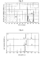
- FIGS. 3A to 3C show X-ray diffraction (XRD) patterns of the compounds of Examples 1 and YAG of Comparative example 1. Note that the XRD patterns were evaluated by an X-ray diffraction device (product name: MultiFlex, made by Rigaku Corporation).
- FIGS. 3A to 3C the XRD pattern of the compound of Example 1 is shown in FIG. 3A . Moreover, the XRD pattern of YAG of Comparative example 1 is shown in FIG. 3B , and the pattern (PDF No. 33-0040) of Al 5 Y 3 O 12 registered in the PDF (Power Diffraction Files) is shown in FIG. 3C .
- the XRD pattern of Example 1 coincides with the XRD pattern of YAG taken as Comparative example 1 and the pattern of Al 5 Y 3 O 12 in terms of shape feature. That is to say, though the XRD pattern of the compound in Example 1 is different from those of Comparative example and Conventional example in intensity ratio of diffraction peaks, the number of diffraction peaks is equal thereto. Moreover, the XRD pattern of Example 1 is formed into a shape in which the respective diffraction peaks in the XRD patterns of Comparative example and Conventional example move to a low angle side as a whole. Note that, in FIGS. 3A to 3C , a correspondence relationship between the diffraction peaks is shown by arrows.
- Such coincidence of the XRD patterns as described above indicates that the compound of Example 1 is a compound having the same garnet crystal structure as that of Y 3 Al 2 (AlO 4 ) 3 . Then, the coincidence indicates that the compound of Example 1 is a compound represented by Ca 2 EuZr 2 (AlO 4 ) 3 .
- FIG. 7A shows an XRD pattern of a compound of Example 2
- FIG. 7B shows an XRD pattern of a compound of Example 3
- FIG. 7C shows an XRD pattern of a compound of Example 4. From FIGS. 3A to 3C and FIGS. 7A to 7C , it is understood that the patterns of FIGS. 7A to 7C are mainly composed of patterns similar to that of the compound of Example 1 shown in FIG. 3A . This matter indicates that the compounds of Example 2, Example 3 and Example 4 include the compound having the garnet structure.
- the compounds of Example 2 and Example 3 include compounds represented by Ca 2 (Y 0.92 Eu 0.08 )Zr 2 (AlO 4 ) 3 and Ca 2 (Gd 0.92 Eu 0.08 )Zr 2 (AlO 4 ) 3 , respectively.
- the compound of Example 4 includes a compound represented by Ca 2 (Tb 0.92 Eu 0.08 )Zr 2 (AlO 4 ) 3 .
- excitation characteristics and light emission characteristics of the compounds (hereinafter, phosphors) of Examples 1 to 4 were evaluated by using a fluorescence spectrophotometer (product name: FP-6500, made by JASCO Corporation) and an instantaneous multi-photometer system (QE-1100, made by Otsuka Electronics Co., Ltd.) in combination.
- a fluorescence spectrophotometer product name: FP-6500, made by JASCO Corporation
- QE-1100 instantaneous multi-photometer system
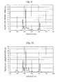
- FIG. 4 shows a light emission spectrum 24a and excitation spectrum 25a of the phosphor (Ca 2 EuZr 2 (AlO 4 ) 3 ) of Example 1.
- FIG. 5 shows a light emission spectrum 24b and excitation spectrum 25b of the phosphor (Y 3 Al 2 (AlO 4 ) 3 :Eu 3+ ) of Comparative example 2. Note that, for the purpose of enhancing measurement accuracy, the instantaneous multi-photometer system was used for measuring the light emission spectra (24a, 24b), and the fluorescence spectrophotometer was used for measuring an excitation spectra (25a, 25b).
- an excitation wavelength at a time of measuring the light emission spectra was set at 250 nm, and a monitoring wavelength at a time of measuring the excitation spectra was set at a light emission peak wavelength.
- a monitoring wavelength at a time of measuring the excitation spectra was set at a light emission peak wavelength.
- the light emission spectra and the excitation spectra are shown while maximum intensities of both thereof are being taken as 1.
- the excitation spectra of the phosphors of Example 1 and Comparative example 2 have the maximum values of the excitation intensities within the ultraviolet wavelength range of less than 300 nm.
- the excitation spectrum of the phosphor of Example 1 and the excitation spectrum of the phosphor of Comparative example 2 also have the excitation peak within the wavelength range of less than 250 nm.
- each of the light emission spectra of the phosphors of Example 1 and Comparative example 2 contains spectrum components derived from the electron energy transition of Eu 3+ . Furthermore, each of the light emission spectra of the phosphors of Example 1 and Comparative example 2 has a shape mainly composed of the light emission spectrum derived from the electron energy transition of Eu 3+ .
- FIGS. 6A, 6B and 6C collectively show the light emission spectra of Y(P,V)O 4 :Eu 3+ (Comparative example 3), Y 2 O 2 S:Eu 3+ (Comparative example 4), and Y 2 O 3 :Eu 3+ (Comparative example 5), respectively.
- Example 1 the shape of the light emission spectrum of Example 1 is similar to that of the Eu 3+ -activated red phosphor such as Y(P,V)O 4 :Eu 3+ (Comparative example 3, FIG. 6A ) and Y 2 O 2 S:Eu 3+ (Comparative example 4, FIG. 6B ), which is put into practical use in a high pressure mercury lamp and a color electron tube. Then, from FIG. 4 and FIG.
- the light emission peak wavelength thereof is 610 nm.
- a half width of the spectrum component present within the wavelength range of 600 nm or more to less than 628 nm is 1 nm or more to less than 10 nm.
- both of a 1/5 spectrum width and a 1/10 spectrum width of the spectrum component in the range are 1 nm or more to less than 10 nm.
- a maximum intensity of the spectrum component of the far-infrared range of 700 nm or more to less than 720 nm is less than 40% of a maximum intensity of the spectrum component present within the range of 600 nm or more to less than 628 nm. This matter indicates that the phosphor of Example 1 can perform the wavelength conversion into the red light containing the red bright line with high visual sensitivity.
- FIG. 8 shows the light emission spectrum of the phosphor (Ca 2 YZr 2 (AlO 4 ) 3 :Eu 3+ ) of Example 2.
- FIG. 9 shows the light emission spectrum of the phosphor (Ca 2 GdZr 2 (AlO 4 ) 3 :Eu 3+ ) of Example 3.
- FIG. 10 shows the light emission spectrum of the phosphor (Ca 2 TbZr 2 (AlO 4 ) 3 :Eu 3+ ) of Example 4. Note that the excitation wavelength at the time of measuring the light emission spectrum was set at 250 nm in a similar way to Example 1. Then, in FIGS. 8 to 10 , each of the light emission spectra is shown while maximum intensity thereof is being taken as 100. Note that, in FIGS. 8 to 10 , the excitation spectra of the compounds of Examples 2 to 4 are omitted; however, were similar to the excitation spectrum of the compound of Example 1.
- the light emission spectra of the phosphors of Examples 2 to 4 had a similar shape to that of the light emission spectrum of the phosphor of Example 1 in the wavelength range of 575 nm or more to 720 nm or less. This matter indicates that the phosphors of Examples 2 to 4 also emit the red light with a good color tone in a similar way to Example 1.
- the light emission spectra ( FIG. 8 and FIG. 9 ) of the phosphor of Example 2 and the phosphor of Example 3 and the light emission spectrum ( FIG. 4 ) of the phosphor of Example 1 are compared with each other.
- the phosphors of Examples 2 and 3 are relatively lower than the phosphor of Example 1.
- the maximum height of the near-infrared bright line in each phosphor of Examples 2 and 3 is smaller than 38% of the maximum height of the red bright line (main bright line) present within the range of 600 nm or more to less than 628 nm. This matter indicates that the phosphors of Example 2 and Example 3 can perform the wavelength conversion into red light containing the red bright line with high visual sensitivity more than the phosphor of Example 1.
- the light emission spectrum ( FIG. 10 ) of the phosphor of Example 4 has a plurality of bright lines in the orange to red wavelength range of 575 nm or more to 720 nm or less in a similar way to Example 1.
- the phosphor of Example 4 contains a spectrum component, which is derived from the electron energy transition of Tb 3+ , in the green wavelength range of 530 nm or more to less than 560 nm.
- the phosphor of Example 4 was a single-compound phosphor, which emits two light emission components derived from the electron energy transition of Eu 3+ and the electron energy transition of Tb 3+ .
- the phosphors of Examples 1 to 4 are compounds containing at least Ca, Eu, Zr, Al and oxygen, and the phosphor of Example 1 is a compound containing Eu by 1 mol in 1 mol thereof. Then, the phosphor of Example 1 is a compound having the garnet crystal structure serving as the end component.
- the phosphors of Examples 1 to 4 are different in composition from the compounds, for example, such as Ca 2 YZr 2 (AlO 4 ) 3 , Ca 2 YHf 2 (AlO 4 ) 3 , Ca 2 LaZr 2 (AlO 4 ) 3 , Ca 2 LuZr 2 (AlO 4 ) 3 and Ca 2 TbZr 2 (AlO 4 ) 3 .
- the phosphors of Examples 1 to 4 have the garnet crystal structure, and accordingly, can be said to be the compounds isomorphic to these compounds.
- the compounds of Examples 1 to 4 which are as described above, are man-made fluorescent minerals, each of which functions as the phosphor.
- the phosphor of this embodiment demonstrates that the spectrum-shape light composed of the red bright line of Eu 3+ can be realized by the garnet-type crystal structure, which has a high degree of freedom in material design, and is configurable by using a variety of elements.
- the inorganic oxide of the present invention has the crystal structure of the garnet, and accordingly, can be used for the man-made jewelry and abrasive, the ceramic material, the electronic material and the like.
- the phosphor of the present invention is the phosphor activated by Eu 3+ having the garnet-type crystal structure, the phosphor can emit the narrowband red light component with good color purity.
- the light-emitting device using this phosphor is useful as an illumination light source, a light-emitting light source, and an electronic instrument.
Abstract
Description
- The present invention relates to a rare earth aluminum garnet-type inorganic oxide, a phosphor, and a light-emitting device using the same.
- Heretofore, many compounds, each of which has a crystal structure of garnet, have been known. Natural garnet is a silicate mineral, and those with high transparency have been valued as jewelry since ancient times. Then, sand of the garnet is industrially used as abrasive.
- As famous garnet, there are almandine (Fe2+ 3Al2(SiO4)3), grossular (Ca3Al2(SiO4)3), and andradite (Ca3Fe3+ 2(SiO4)3). Moreover, there are also pyrope (Mg3Al2(SiO4)3), spessartine (Mn3Al2(SiO4)3), uvarovite (Ca3Cr2(SiO4)3), and the like.
- Here, a compound represented by Y3Al2(AlO4)3, (which is hereinafter also referred to as YAG), is an artificial mineral synthesized based on the garnet, and is widely known as a name of yttrium aluminum garnet. Then, YAG is used for the purpose of a solid-state laser, translucent ceramics, a phosphor and the like (for example, refer to Non-Patent Literature 1). Moreover, it is known that the YAG includes many modification examples. Typical modification examples of YAG include Tb3Al2(AlO4)3 (for example, refer to Patent Literature 1), Y3Ga2(AlO4)3 (for example, refer to Non-Patent Literature 1), Y3Mg2(AlO4)(SiO4)2 (for example, refer to Patent Literature 2) and the like.
- Here, the "phosphor" stands for a compound that emits fluorescence by being given a stimulus such as ultraviolet excitation. Then, when extranuclear electrons of a specific atom that composes the compound are excited by the ultraviolet ray and the like and return to a ground state thereof, then visible light is emitted due to a difference in energy level. For example, rare earth ions and transition metal ions (Ce3+, Tb3+, Eu3+, Mn2+, Mn4+, Fe3+, Cr3+ and the like), each of which functions as a light emission center, are contained in such a compound as YAG, whereby the phosphor is obtained.
- Then, a YAG:Ce phosphor activated by Ce3+ is particularly known as a high-efficiency phosphor, and is used in numerous light-emitting devices (for example, refer to
Patent Literatures 3 and 4 and Non-Patent Literature 1). The YAG:Ce phosphor is characterized in, at a time of being irradiated with a corpuscular ray or an electromagnetic wave, being excited and emitting super short-afterglow visible light from yellow to green (for example, refer to Non-Patent Literature 1). - Meanwhile, a YAG:Eu phosphor activated by Eu3+ is also known, and study thereof as a red phosphor for a plasma display device (PDP) is made (for example, refer to Non-Patent Literature 1).
-
- [PTL 1] Japanese Unexamined Patent Application Publication (Translation of
PCT Application) No. 2003-505582 - [PTL 2] International Publication No.
2010/043287 - [PTL 3] Japanese Patent No.
3503139 - [PTL 4] United States Patent No.
6812500 - [NPL 1] "Phosphor Handbook", edited by Keikoutaidougakukai, Ohmsha, Ltd., December 1987, p. 332
- However, the conventional Eu3+-activated phosphor having a garnet structure does not emit red light with a good color tone. Therefore, it has been difficult to provide a light-emitting device, which emits a red light component with a good color tone by using the conventional Eu3+-activated phosphor having the garnet structure.
- The present invention has been made in consideration of such a problem as described above, which is inherent in the prior art. Then, it is an object of the present invention to provide a rare earth aluminum garnet-type inorganic oxide and a phosphor, each of which is capable of emitting red light, which has narrowband characteristics, and further, has a good color tone, and to provide a light-emitting device using the same.
- An inorganic oxide according to a first aspect of the present invention has a composition represented by General formula:
M2LnX2(AlO4)3
(where M includes Ca, Ln includes Eu, and X includes at least either one of Zr and Hf). Then, a crystal structure of the inorganic oxide is a garnet-type structure. Eu3+ in the inorganic oxide emits a plurality of bright line-like fluorescent components, and a principal bright line of the fluorescent component is present within a wavelength range of 600 nm or more to less than 628 nm. Moreover, a maximum height of the bright line present within a wavelength range of 700 nm or more to less than 720 nm is less than 60% of a maximum height of the principal bright line. - An inorganic oxide according to a second aspect of the present invention is the inorganic oxide according to the first aspect, wherein M includes Ca and at least one element selected from the group consisting of alkali earth metal, Fe, Mn, Zn Cd, Co and Cu. Then, Ln includes Eu and at least one element selected from the group consisting of Sc, Y, La, Ce, Pr, Nd, Sm, Tb, Gd, Dy, Ho, Er, Tm, Yb, Lu, In, Sb and Bi. X includes at least either one of Zr and Hf and at least one element selected from the group consisting of Si, Ge, Ti, Sn and Pb.
- An inorganic oxide according to a third aspect of the present invention is the inorganic oxide according to the second aspect, wherein M includes Ca and at least one element selected from the group consisting of alkali earth metal, Mn and Zn. Ln includes Eu and at least one element selected from the group consisting of Y, La, Ce, Pr, Sm, Tb, Gd, Lu and In. X includes at least either one of Zr and Hf and at least one element selected from the group consisting of Si, Ge, Ti and Sn.
- An inorganic oxide according to a fourth aspect of the present invention is the inorganic oxide according to the first aspect, wherein M is Ca, and Ln is Eu.
- An inorganic oxide according to a fifth aspect of the present invention is the inorganic oxide according to either one of the second and third aspects, wherein Ln is an element including Eu and at least one element selected from the group consisting of Y, Gd and Tb.
- An inorganic oxide according to a sixth aspect of the present invention is the inorganic oxide according to the fifth aspect, wherein a number of Eu moles in 1 mol of the inorganic oxide exceeds 0 mol and is less than 0.1 mol.
- A solid solution according to a seventh aspect of the present invention is a solid solution of the inorganic oxide according to any one of the first to fifth aspects and a compound that is solid-solved with the inorganic oxide and is different from the inorganic oxide in composition. Then, a number of Eu moles in 1 mol of the solid solution is 0.1 mol or more to less than 3 moles, and a crystal structure of the solid solution is the garnet-type structure.
- A solid solution according to an eighth aspect of the present invention is the solid solution according to the seventh aspect, wherein the solid solution has a composition represented by General formula: A3D2(EG4)3 (where A includes Ca and Eu and at least one element selected from alkali metal, alkali earth metal and a rare earth element, D includes the element represented by X and at least one element selected from Mg, Sc, Y, Ti, V, Zr, Hf, Zn, Al, Ga, In, Ge and Sn, E includes Al and at least one element selected from Zn, Al, Si, Ge and P, and G includes O).
- A phosphor according to a ninth aspect of the present invention is composed of the inorganic oxide according to any one of the first to sixth aspects or the solid solution according to the seventh or eighth aspect.
- A phosphor according to a tenth aspect of the present invention is the phosphor according to the ninth aspect, wherein the inorganic oxide or the solid solution forms a main skeleton of a crystal.
- A phosphor according to an eleventh aspect of the present invention is the phosphor according to either one of the ninth and tenth aspects, wherein a 1/5 spectrum width of a light emission spectrum serving as the principal bright line is 1 nm or more to less than 10 nm.
- A light-emitting device according to a twelfth aspect of the present invention includes the phosphor according to any one of the ninth to eleventh aspects.
- The inorganic oxide of the present invention becomes the phosphor, which is capable of emitting the red light, which has the narrowband characteristics, and has good color purity. Moreover, the light-emitting device using the phosphor of the present invention is capable of emitting intense light containing a narrowband red light component in which a light emission spectrum half width is 1 nm or more to less than 10 nm.
-
-
FIGS. 1A and 1B are schematic views for explaining a light-emitting device according to an embodiment of the present invention. -
FIG. 2 is a cross-sectional view schematically showing an example of a semiconductor light-emitting device according to the embodiment of the present invention. -
FIG. 3 is a graph showing XRD patterns of compounds in Example 1 and Comparative example 1. -
FIG. 4 is a graph showing an excitation spectrum and light emission spectrum of a phosphor in Example 1. -
FIG. 5 is a graph showing an excitation spectrum and light emission spectrum of a phosphor in Comparative example 2. -
FIGS. 6A to 6C are graphs showing excitation spectra in Comparative examples 3 to 5. -
FIGS. 7A to 7C are graphs showing XRD patterns of compounds in Comparative examples 2 to 4. -
FIG. 8 is a graph showing an excitation spectrum of a phosphor in Example 2. -
FIG. 9 is a graph showing an excitation spectrum of a phosphor in Example 3. -
FIG. 10 is a graph showing an excitation spectrum of a phosphor in Example 4. - A description is made below in detail of a rare earth aluminum garnet-type inorganic oxide and a phosphor according to an embodiment of the present invention, and of a light-emitting device using the phosphor. Note that dimensional ratios of the drawings are exaggerated for convenience of explanation, and are sometimes different from actual ratios.
- First, in general, "mineral" is a solid inorganic substance, which is naturally produced, and refers to one, in which a composition can be written by a chemical formula, an array of constituent elements is regular, that is, crystalline, and physical properties remain within a narrow range. A term opposite to the naturally produced mineral described above includes artificial mineral, which is also called man-made mineral. The artificial mineral refers to one which has the same component, structure and texture as those of the naturally produced mineral and achieved by a chemical/physical method. Note that the artificial mineral sometimes includes an inorganic solid, in which a structure and an elemental composition are the same as those of the natural mineral, and a component or a composition is different from that of the natural mineral, and in addition, more broadly, also includes a general inorganic solid in some case.
- Meanwhile, it is known that elements, which are similar in charge or ion radius to one another, are substitutable for one another while keeping the same crystal structure, and accordingly, form a group of minerals having similar chemical formulae. The matter that the substances having similar chemical compositions take the same crystal structure is referred to as "isomorphism" in the field of lithology and mineralogy. Therefore, mineral species belonging to the group of the garnet are compounds isomorphic to one another.
- Moreover, it is also known that a different type of ions substitutes and enters specific sites in the crystal structure, and that the mineral species exhibit a broad composition change. A composition of the mineral concerned can be easily expressed by a mixture ratio of minerals having compositions of both ends in the composition change. The mineral as described above is referred to as a "solid solution" since the mineral generates such a uniform phase as in mixture of solutions although the mineral is solid.
- Then, in this description, a compound that has the crystal structure of the garnet and contains at least rare earth, aluminum and oxygen as main components is referred to as a "rare earth aluminum garnet-type inorganic oxide". Moreover, a rare earth aluminum garnet-type inorganic oxide which functions as a phosphor is referred to as a "rare earth aluminum garnet-type phosphor".
- First, a description is made of the rare earth aluminum garnet-type inorganic oxide according to the embodiment of the present invention.
- The rare earth aluminum garnet-type inorganic oxide according to this embodiment is an inorganic chemical substance created artificially with reference to natural mineral. Then, the inorganic oxide at least contains Eu3+, in which a crystal structure is a garnet structure.
- Specifically, the inorganic oxide has a composition represented by General formula (1), in which the crystal structure is the garnet structure. (AlO4) in General formula (1) has a tetrahedron structure.
M2LnX2(AlO4)3 (1)
where M includes calcium (Ca), Ln includes europium (Eu), and X includes at least either one of zirconium (Zr) and hafnium (Hf). Moreover, Eu3+ in the above-described inorganic oxide emits a plurality of bright line-like fluorescent components. The fluorescent components are emitted when an external stimulus to be described later is given to Eu3+ in the inorganic oxide. Moreover, a principal bright line of the above-described fluorescent components is present within a wavelength range of 600 nm or more to less than 628 nm. Then, a maximum height of a bright line present within a wavelength range of 700 nm or more to less than 720 nm is less than 60%, preferably, less than 40% of a maximum height of the above-described principal bright line. Here, the "principal bright line" refers to a bright line that has a maximum value within the range of 600 nm or more to less than 628 nm. The inorganic oxide of this embodiment, which is represented by General formula M2LnX2(AlO4)3 as described above, can exert novel fluorescent characteristics as will be described later. - Moreover, in the inorganic oxide of this embodiment, if the number of Eu atoms in General formula (1) exceeds 0 and is 1 or less, then a function as the phosphor is observed. However, in order to form the inorganic oxide into a phosphor in which a feature is conspicuous in terms of composition, it is preferable that the number of Eu atoms be 0.1 or more to 1 or less. In a case of using the inorganic oxide in which the number of Eu atoms is set within this range as the phosphor, the phosphor becomes capable of emitting red light efficiently since Eu functions as a light emission center as will be described later.
- Specifically, the rare earth aluminum garnet-type inorganic oxide of this embodiment contains low-concentration or high-concentration Eu, and thereby functions as fluorescent mineral (that is, as an inorganic phosphor). Note that the expression "the number of Eu atoms in General formula (1) is 0.1 or more to 1 or less" is also presentable as an expression "the number of Eu moles in 1 mol of the inorganic oxide represented by General formula (1) is 0.1 mol or more to 1 mol or less".
- Here, in general, the inorganic compound has numerous modification examples. Moreover, as mentioned above, the mineral having the crystal structure of the garnet also has numerous modification examples. Therefore, the rare earth aluminum garnet-type inorganic oxide according to this embodiment also incorporates numerous modification examples somewhat different from that in General formula (1) within the scope of not damaging the crystal structure of the garnet. This point is described by mentioning specific examples. That is to say, an elemental composition of the inorganic oxide according to this embodiment is, for example, Ca2EuX2(AlO4)3. At this time, it is interpreted that the inorganic oxide according to this embodiment is isomorphic to Ca2EuX2(AlO4)3, and includes a modification example in which that the above-described Ca2EuX2(AlO4)3 serves as an endmember of the solid solution. Note that the above-described "end member" is a term of the lithology, and refers to a component that forms a limit of the composition of the solid solution.
- Then, as mentioned above, M in General formula (1) includes at least calcium (Ca). However, calcium is partially replaceable by an element that is other than calcium and can become divalent ions. Therefore, M in General formula (1) may include Ca and at least one element selected from the group consisting of alkaline earth metal, Fe(II), Mn, Zn, Cd, Co and Cu. Moreover, as the alkaline earth metal, Mg, Sr and Ba are particularly preferable. Note that, in the case of using the inorganic oxide of this embodiment as the phosphor, it is particularly preferable that M in General formula (1) include Ca and at least one element selected from the group consisting of the alkaline earth metal, Mn and Zn.
- In the inorganic oxide of this embodiment, it is preferable that calcium (Ca) occupy a large majority of M in General formula (1). Here, "Ca occupies a large majority of M" means that Ca atoms occupy a large majority of an atom group that occupies M. If the composition as described above is employed, then the inorganic oxide of this embodiment can function as a mother material of the higher-efficiency phosphor or as the higher-efficiency phosphor itself. Note that M may be occupied by only calcium.
- Moreover, as mentioned above, Ln in General formula (1) includes at least europium (Eu). However, europium is partially replaceable by an element that is other than europium and can become trivalent ions, and particularly, by a rare earth element. As the element that can become the trivalent ions, there are mentioned Sc, Y, La, Ce, Pr, Nd, Sm, Tb, Gd, Dy, Ho, Er, Tm, Yb, Lu, In, Sb, Bi and the like. Preferably, the element is at least one selected from Sc, Y, La, Ce, Pr, Nd, Sm, Tb, Gd, Dy, Ho, Er, Tm, Yb, Lu and the like. Therefore, Ln in General formula (1) may include Eu and at least one element selected from the group consisting of Sc, Y, La, Ce, Pr, Nd, Sm, Tb, Gd, Dy, Ho, Er, Tm, Yb, Lu, In, Sb and Bi. Note that, in the case of using the inorganic oxide of this embodiment as the phosphor, it is particularly preferable that Ln in General formula (1) include Eu and at least one element selected from the group consisting of Y, La, Ce, Pr, Sm, Tb, Gd, Lu and In.
- In the inorganic oxide of this embodiment, in order to compose the phosphor in which the feature is conspicuous in terms of composition, it is preferable that europium (Eu) occupy a large majority of Ln in General formula (1). Here, "Eu occupies a large majority of Ln" means that Eu atoms occupy a large majority of an atom group that occupies Ln. If the composition as described above is employed, then Eu itself becomes the light emission center, and accordingly, the inorganic oxide of this embodiment can function as a mother material of the higher-efficiency phosphor or as the higher-efficiency phosphor itself. Note that Ln may be occupied by only europium.
- In the inorganic oxide of this embodiment, in order to compose the phosphor in which the feature is conspicuous in terms of composition, it is preferable that Ln in General formula (1) contain Eu and at least one element selected from the group consisting of Y, Tb and Gd.
- Moreover, in the inorganic oxide of this embodiment, it is also preferable that Ln in General formula (1) contain at least Eu, and that the large majority of Ln be occupied by at least one element selected from the group consisting of yttrium (Y), gadolinium (Gd) and terbium (Tb). Here, "the large majority of Ln is occupied by at least one element selected from the group consisting of Y, Gd and Tb" means that the majority of the atom group that occupies Ln is occupied by at least one type of atoms, which is selected from the group consisting of Y atoms, Gd atoms and Tb atoms. In a case where the inorganic oxide has such a composition, the phosphor that emits red light with a good color tone can be obtained, in particular, by setting the number of Eu atoms in General formula (1) at a low concentration that exceeds 0 and is less than 0.1. In other words, even if the number of Eu moles in 1 mol of the inorganic oxide represented by General formula (1) is set to exceed 0 mol and to be less than 0.1 mol, the phosphor that emits red light with a good color tone can be obtained.
- Furthermore, as mentioned above, X in General formula (1) includes at least either one of zirconium (Zr) and hafnium (Hf). Zirconium and hafnium are partially replaceable by an element that is other than these elements and can become tetravalent ions. As the element that can become the tetravalent ions, Si, Ge, Ti, Sn, Pb and the like are mentioned, and Sn is preferable. Therefore, X in General formula (1) may include at least either one of Zr and Hf, and at least one element selected from the group consisting of Si, Ge, Ti, Sn and Pb. Note that, in the case of using the inorganic oxide of this embodiment as the phosphor, it is particularly preferable that X in General formula (1) include at least either one of Zr and Hf and at least one element selected from the group consisting of Si, Ge, Ti and Sn.
- Moreover, in the inorganic oxide, it is preferable that zirconium (Zr) and/or hafnium (Hf) occupy a large majority of X in General formula (1). Here, "Zr and/or Hf occupies a large majority of the element X" means that Zr atoms and/or Hf atoms occupy a large majority of an atom group that occupies X. If the composition as described above is employed, then the inorganic oxide of this embodiment can function as the mother material of the higher-efficiency phosphor or as the higher-efficiency phosphor itself. Note that X may be occupied by only Zr and/or Hf.
- As such a compound, which is preferable as a fluorescent substance and isomorphic to the inorganic oxide of this embodiment, there are exemplified Ca2(Eu,Ce)Zr2(AlO4)3, Ca2(Y,Eu)Zr2(AlO4)3, Ca2(Eu,Tb)Zr2(AlO4)3 and the like. Moreover, Ca2(La,Eu)Hf2(AlO4)3, (Ca,Sr)2(Y,Eu)(Zr,Hf)2(AlO4)3, (Ca,Mg)2EuZr2(AlO4)3, Ca2(Eu,Pr)Zr2(AlO4)3 and the like. Furthermore, Ca2(Eu,Tb,Ce)Zr2(AlO4)3 and the like are also exemplified.
- The inorganic oxide of this embodiment may form a solid solution with a compound, which is solid-solved with the inorganic oxide, and is different in composition from the inorganic oxide. Then, it is preferable that this solid solution have the garnet structure in a similar way to the inorganic oxide of this embodiment. The solid solution as described above can also become the rare earth aluminum garnet-type phosphor having the novel fluorescent characteristics.
- Note that, in order to cause Eu, which is contained in the solid solution, to function as the light emission center as mentioned above, at least Eu just needs to be contained therein. Note that, in order to obtain such red light that is relatively good in terms of color purity, it is sufficient if the number of Eu moles in 1 mol of the above-described solid solution is set, for example, within a range exceeding 0 mol to less than 0.1 mol, or a range of 0.1 mol or more to less than 3 moles.
- Here, as the compound solid-solved in the inorganic oxide of this embodiment, a compound having the garnet structure is preferable, and particularly, a compound isomorphic to the above-described inorganic oxide is more preferable. In such a way, properties inherent in the above-described compound become similar to those of the inorganic oxide, and accordingly, it becomes possible to easily form the solid solution of this embodiment, which has the crystal structure of the garnet. Examples of the compound that are solid-solved in the inorganic oxide of this embodiment and form the solid solution will be described later.
- Incidentally, as mentioned above, it is known that the natural garnet is usually present as the solid solution of the plural types of garnets which become the end members. Meanwhile, for example, Ca2EuZr2(AlO4)3, Ca2EuHf2(AlO4)3 and the like in the inorganic oxide of this embodiment can be regarded as the end members. Therefore, in accordance with the solid solution of the inorganic oxide of this embodiment and of the compound that has such a different garnet structure from that of the inorganic oxide and can become the end member, it is possible to obtain numerous types of the solid solutions, each of which has the crystal structure of the garnet.
- Then, when the solid solution of this embodiment has the garnet structure as mentioned above, it is preferable that the solid solution have a composition represented by General formula (2).
A3D2(EG4)3 (2)
- Here, (EG4) in General formula (2) has a tetrahedral structure. E includes Al and at least one element selected from Zn, Al, Si, Ge and P. G includes O.
- Such a tetrahedron (EG4) in General formula (2) corresponds to the (AlO4) tetrahedron in the inorganic oxide represented by General formula (1). This tetrahedron (EG4) is partially replaceable by tetrahedrons other than the (AlO4) tetrahedron. As the tetrahedrons other than the above-described (AlO4) tetrahedron, tetrahedrons such as (SiO4), (GeO4), (SiO3N), (ZnO4), (FeO4), (VO4) and (PO4) are mentioned. Note that, in a case where the valence of the tetrahedron is deviated from the valence of the (AlO4) tetrahedron, that is, the negative pentavalent value in response to a form of the solid solution, then the solid solution is composed while being attended with charge compensation provided by any of Ca, Eu and the element X.
- The element corresponding to A in General formula (2) is Ca and Eu. Moreover, at least either one of Ca and Eu in the element A is partially replaceable by an element that can become divalent or trivalent ions. Furthermore, at least either one of Ca and Eu in the element A is replaceable by an element other than the element that can become the divalent or trivalent ions. As the element that can partially replace Ca and Eu, an element is preferable, which can become monovalent to trivalent ions while being attended with charge compensation provided by at least either one of the element X in General formula (1) and the tetrahedron other than the (AlO4) tetrahedron. In addition, an element is preferable, in which an ion radius is 0.6 Å or more to less than 1.7 Å, and particularly, 0.8 Å or more to less than 1.4 Å.
- As such an element that can partially replace Ca and Eu, in which the ion radius is 0.6 Å or more to less than 1.7 Å, there can be mentioned: alkali metal such as Li, Na, K, Rb and Cs; and alkali earth metal such as Mg, Ca, Sr and Ba. Moreover, as such an element, there can also be mentioned: rare earth elements such as Sc, Y, La, Ce, Pr, Nd, Sm, Tb, Gd, Tb, Dy, Ho, Er, Tm, Yb and Lu; and transition metal elements such as Mn, Fe, Co, Cu and Zn. Note that, in this description, the "ion radius" means an ion radius of Ahrens.
- D in General formula (2) includes the element represented by X in General formula (1) and at least one element selected from Mg, Sc, Y, Ti, V, Zr, Hf, Zn, Al, Ga, In, Ge and Sn. D in General formula (2) is an element corresponding to the element X in General formula (1). As mentioned above, the element X in General formula (1) includes at least either one of Zr and Hf. Note that the element D in General formula (2) can be partially replaced by the element that can become the tetravalent ions. Moreover, the element D can also be replaced by the element other than the element that can become the tetravalent ions. As the element that can partially replace the element D, an element is preferable, which can become divalent or trivalent ions while being attended with charge compensation provided by at least any one of Ca, Tb and the tetrahedron other than the (AlO4) tetrahedron. In addition, moreover, as the element that can partially replace the element D, an element is preferable, in which an ion radius is 0.4 Å or more to less than 0.95 Å, and particularly, 0.5 Å or more to less than 0.8 Å.
- As such an element in which the ion radius is 0.4 Å or more to less than 0.95 Å, there are mentioned: the rare earth elements such as Mg, Sc and Y; and transition metal and typical element metal, such as Ti, V, Cr, Mn, Fe, Co, Ni, Cu, Zn, Al, Ga, and In.
- Note that, in the solid solution represented by General formula (2), it is preferable that an index of the partial replacement of A, D and (EG4) be a half or less with respect to one piece of such a replacement target element, and moreover, be a half or less with respect to one piece of the (AlO4) tetrahedron in the (AlO4) tetrahedron. In other words, it is preferable that, in the solid solution, Ca and Eu occupy a large majority of A in General formula (2). Moreover, it is preferable that, in the solid solution, the element X occupy a large majority of D in General formula (2). Furthermore, it is preferable that, in the solid solution, (AlO4) occupy a large majority of (EG4) in General formula (2).
- As described above, the inorganic oxide according to this embodiment is capable of forming the solid solution with the compound isomorphic to the inorganic oxide. Then, as mentioned above, in order to make the solid solution characteristic in terms of the composition, it is preferable that the number of Eu moles in 1 mol of the solid solution be 0.1 mol or more to less than 3 moles. Note that, even if the number of Eu moles in 1 mol of the solid solution exceeds 0 mol and is less than 0.1 mol, the color purity of the red light can be enhanced in comparison with the conventional product.
- As specific examples of the compound that forms the solid solution with the inorganic oxide according to this embodiment, there can be mentioned Y3Al2(AlO4)3, Tb3Al2(AlO4)3, Y3Ga2(AlO4)3, Ca2YZr2(AlO4)3 and Ca2YHf2(AlO4)3. Moreover, as the above-described compound, Ca2LaZr2(AlO4)3, Ca2LuZr2(AlO4)3, Ca2LuHf2(AlO4)3, Ca2YSn2(AlO4)3, Ca2LaSn2(AlO4)3, Ca2TbZr2(AlO4)3 and the like can also be mentioned. Note that the compound that forms the solid solution is not limited to these.
- The solid solution of this embodiment may contain at least one element, which is selected from H, B, C, S, F, Cl and the like, as well as the above-mentioned elements. Moreover, the solid solution of this embodiment may contain nitrogen. That is to say, the element G in the tetrahedron (EG4) in General formula (2) may contain nitrogen as well as oxygen, and the solid solution may be an oxynitride.
- Shapes of the rare earth aluminum garnet-type inorganic oxide and solid solution of this embodiment are not particularly limited. That is to say, in a similar way to the conventional YAG and the like, the rare earth aluminum garnet-type inorganic oxide and the solid solution are formable into compounds with a variety of shapes including a crystalline state of a single crystal or a polycrystal (ceramics), or a thin film shape, a thick film shape, a block shape, a granular shape, a powder shape, a nano-particle shape, and the like. Moreover, in a similar way to the natural garnet, the rare earth aluminum garnet-type inorganic oxide and solid solution of this embodiment are usable, for diverse purposes, as new industrial materials such as man-made jewel, abrasive, a ceramic material and an electron material.
- It is possible to produce the rare earth aluminum garnet-type inorganic oxide of this embodiment by a method known in public. Specifically, in a similar way to YAG, the rare earth aluminum garnet-type inorganic oxide can be synthesized by using a solid phase reaction known in public.
- First, a rare earth oxide (Sn2O3, Y2O3, La2O3, CeO2, Pr6O11, Eu2O3, Gd2O3, Tb4O7, Lu2O3), which is universal ceramic raw powder, or the like is prepared. Moreover, alkaline earth carbonate (CaCO3), Al2O3, Ga2O3, ZrO2, HfO2 or the like is prepared. Next, such types of raw material powder are blended with each other so as to obtain a stoichiometric composition of a desired inorganic oxide or a composition approximate thereto, and are sufficiently mixed with each other by using a mortar, a ball mill or the like. Thereafter, the mixed raw materials are fired by an electric furnace or the like by using a firing container such as an alumina melting pot, whereby the inorganic oxide of this embodiment can be prepared. Note that, in an event of firing the mixed raw materials, it is preferable to heat the mixed raw materials at a firing temperature of 1500 to 1700°C for a few hours under the atmosphere or a weakly reductive atmosphere.
- Next, a description is made of the rare earth aluminum garnet-type phosphor according to the embodiment of the present invention.
- The phosphor according to this embodiment contains an inorganic oxide having the composition represented by General formula (1), in which a crystal structure is the garnet structure. Then, Eu3+ contained in the above-described inorganic oxide emits a plurality of bright line-like fluorescent components. The fluorescent components are emitted when an external stimulus to be described later is given to Eu3+ in the inorganic oxide. Moreover, a principal bright line of the above-described fluorescent components is present within a wavelength range of 600 nm or more to less than 628 nm. Then, a maximum height of a bright line present within a wavelength range of 700 nm or more to less than 720 nm is less than 60%, preferably, less than 40% of a maximum height of the above-described principal bright line.
- Then, it is preferable that the phosphor be composed by using the rare earth aluminum garnet-type inorganic oxide (including the above-described solid solution) as a main skeleton of the crystal. That is to say, in the above-mentioned inorganic oxide, as will be described later, the inorganic oxide itself has a function to emit the fluorescence, and accordingly, the phosphor of this embodiment uses the properties of the inorganic oxide exclusively. In other words, the phosphor of this embodiment is a compound, which is mainly composed of the above-described inorganic oxide, and emits the fluorescence.
- In general, the phosphor refers to a compound in which a part of the elements composing the crystal of the compound is partially replaced by the element that can become the ions having characteristics to emit the fluorescence. The ions having such characteristics as described above are usually referred to as the "light emission center". Then, as mentioned above, the inorganic oxide of this embodiment includes at least calcium (Ca), europium (Eu), zirconium (Zr) and/or hafnium (Hf), aluminum (Al) and oxygen (O) as the constituent elements of the crystal. Eu is an element capable of forming Eu3+ known as the light emission center that emits the red light. Moreover, Eu3+ is an ion, which is less likely to be quenched although a concentration thereof is increased, and is known as a light emission center with less concentration quenching. Therefore, the rare earth aluminum garnet-type inorganic oxide (including the above-described solid solution) of this embodiment has a function to emit the fluorescence from the inorganic oxide itself. That is to say, the phosphor of this embodiment has such characteristics that at least Eu3+ can become the light emission center and that Eu3+ can emit the fluorescent component.
- Incidentally, as a red phosphor with activated Eu3+, which has been heretofore widely used for a light-emitting device, Y2O3:Eu3+, Y2O2S:Eu3+, YVO4:Eu3+, Y(P,V)O4:Eu3+, (Y,Gd)BO3:Eu3+ and the like are present. Moreover, besides the above, Y2SiO5:Eu3+, Y3Al2(AlO4)3:Eu3+ and the like are known. Among these red phosphors, particularly, Y2O3:Eu3+, Y2O2S:Eu3+, YVO4:Eu3+, Y(P,V)O4:Eu3+ are red phosphors which emit the red light that is good in terms of the color purity. Then, in a case where Eu3+ in the phosphor of this embodiment functions as the light emission center, it becomes possible to realize a red phosphor having a light emission spectrum equivalent to that of the conventional Y2O2S:Eu3+ red phosphor, Y(P,V)O4:Eu3+ red phosphor or the like.
- As described above, the inorganic oxide of this embodiment has a function to emit intense fluorescence by itself. However, it is preferable to modify the inorganic oxide of this embodiment as follows from a viewpoint of obtaining a higher-efficiency phosphor.
- First, a description is made of elements which are preferably not contained in the inorganic oxide of this embodiment. For example, transition metal such as Fe, Co, Ni, V, Cu, Cr and Ti is known as an element that forms an ion causing a decrease of light emission intensity of the phosphor. Then, such an ion decreases the light emission intensity of the phosphor, and accordingly, is usually called a killer center. Therefore, it is preferable that the phosphor of this embodiment should not contain these transition metals.
- Next, a description is made of elements or ions which are preferably contained in the inorganic oxide of this embodiment. It is more preferable that the phosphor of this embodiment allow the above-described inorganic oxide or solid solution to contain a large amount of the ion that becomes the light emission center. That is to say, the inorganic oxide of this embodiment and the solid solution containing the same include at least Eu that forms Eu3+ as the light emission center. However, in order to allow the phosphor of this embodiment to emit light more efficiently, it is also preferable to add another light emission center in addition to Eu3+. Note that, even in a case of not radiating the fluorescence generated by Eu3+, the inorganic oxide, the solid solution and the phosphor, which satisfy the composition of the present invention, are incorporated in the technical scope of the present invention if such a light emission center ion other than Eu3+ emits the fluorescence.
- As the light emission center other than Eu3+, there is used an ion or the like, the ion being capable of emitting the fluorescence by electron energy transition in the crystal of the compound that functions as the mother material of the phosphor, that is, the above-described inorganic oxide and solid solution. Specifically, it is preferable to use, as the light emission center, at least one of: Sn2+, Sb3+, Tl+, Pb2+ and Bi3+, each of which is called an ns2-type ion light emission center; and Cr3+, Mn4+, Mn2+ and Fe3+, each of which is called a transition metal ion light emission center. Moreover, it is also preferable to use, as the light emission center, at least one of Ce3+, Pr3+, Nd3+, Sm3+, Tb3+, Gd3+, Dy3+, Ho3+, Er3+, Tm3+, Yb3+, Sm2+, Eu2+ and Yb2+, each of which is called a rare earth ion light emission center.
- Note that it is more preferable that the light emission center in the phosphor of this embodiment be Eu3+ and at least one ion selected from Mn4+, Mn2+, Ce3+, Pr3+ and Tb3+. In this case, it becomes possible to obtain a phosphor that emits multi-purpose visible light components, that is, blue, blue green, green, yellow, orange, red and white. Moreover, it is particularly preferable that the light emission center in the phosphor of this embodiment be Eu3+ and at least one ion selected from Mn2+, Ce3+, Pr3+ and Tb3+. In this case, it becomes possible to obtain a phosphor that emits blue green light, green light, orange light, red light or white light, which are more frequently used in a display device and a lighting device.
- As mentioned above, it is preferable that the phosphor of this embodiment contains not only Eu3+ but also, as a coactivator, the other light emission center than Eu3+, and particularly, at least one ion selected from Ce3+, Pr3+, Tb3+ and Mn2+. For example, Ce3+ does not only function as the light emission center but also has a function to absorb the short-wavelength visible light in a case of being present in crystal lattices of the above-described inorganic oxide and solid solution. Therefore, it is also preferable that the phosphor of this embodiment is allowed to not only contain Eu3+ but also further contain Ce3+. In such a way, Ce3+ absorbs the short-wavelength visible light, and accordingly, it becomes possible to obtain a phosphor that absorbs the short-wavelength visible light.
- Moreover, Ce3+ also functions as a sensitizer, and can increase light emission intensity of Pr3+ having a bright line-like red component. Therefore, it is also preferable that the phosphor of this embodiment contains not only Eu3+ and Ce3+ but also Pr3+. In such a way, it becomes possible to obtain a phosphor that emits not only the light emission component of Eu3+ but also a light emission component of Pr3+. That is to say, it becomes possible to obtain a phosphor that combines properties to absorb the short-wavelength visible light and properties to emit the bright-line like red light generated by Eu3+ and the bright-line like red light generated by Pr3+.
- Furthermore, Ce3+ also functions as a sensitizer of Mn2+, and can increase light emission intensity of Mn2+ having an orange component with a wide spectrum width. Therefore, it is also preferable that the phosphor of this embodiment contain not only Eu3+ and Ce3+ but also Mn2+. In such a way, it becomes possible to obtain a phosphor that emits not only the light emission component of Eu3+ but also a light emission component of Mn3+.
- Moreover, it is also preferable that the phosphor of this embodiment is allowed to also contain Tb3+ as the other light emission center than Eu3+. In such a way, a phosphor, which emits a light component that combines a red bright line emitted by Eu3+ and a green bright line emitted by Tb3+ with each other, can be obtained. In a case where the phosphor of this embodiment contains not only Tb3+ but also Ce3+, then light energy absorbed by Ce3+ is moved to Tb3+ efficiently, and accordingly, a phosphor, which can perform wavelength conversion for the short-wavelength visible light, into at least the green bright line, can be obtained. Moreover, this phosphor becomes a phosphor in which the light energy moved to Tb3+ is moved to Eu3+.
- As described above, in the rare earth aluminum garnet-type phosphor of this embodiment, it is preferable that the above-mentioned light emission center be contained in the above-described inorganic oxide or solid solution, which contains Eu. In such a way, the above-described inorganic oxide and solid solution are easily excited by an external stimulus, for example, irradiation of a corpuscular ray (α-ray. β-ray, electron beam) and an electromagnetic wave (γ-ray, X-ray, vacuum ultraviolet ray, ultraviolet ray, visible light ray) and the like, and become capable of emitting the fluorescence. Note that, if the fluorescence emitted from the phosphor of this embodiment is any electromagnetic wave selected from the ultraviolet ray, the visible light ray and the ultraviolet ray, then the fluorescence can be used for a light-emitting device to be described later; however, preferable fluorescence for practical use is the visible light. If the emitted fluorescence is the visible light, then the fluorescence can be widely used, for example, for the light-emitting device for the display device and the lighting device.
- As mentioned above, it is preferable that the rare earth aluminum garnet-type phosphor of this embodiment have not only Eu3+ but also the other light emission center than Eu3+. Specifically, it is preferable that the rare earth aluminum garnet-type phosphor in this embodiment contains, in the crystalline lattices, Ce, Pr, Tb and Mn as the rare earth element other than Eu. In such a way, a phosphor can be obtained, the phosphor emitting light, in which at least one light emission component of Ce3+, Pr3+, Tb3+ and Mn2+ is added to the light-emitting element of Eu3+, in a case of being excited. As a result, the phosphor of this embodiment becomes capable of arbitrarily controlling a color tone of the luminescent color. Note that, because of similarity in ion radius, it is also preferable that La and Gd be contained as the other rare earth element than Eu in the crystalline lattices. In such a way, a phosphor, which emits the red light with good color purity, the red light being generated by Eu3+, is obtained.
- As mentioned above, the number of Eu moles per 1 mol of the inorganic oxide that becomes the phosphor is, for example, within the range exceeding 0 mol to less than 0.1 mol, or the range of 0.1 mol or more to less than 1 mol. Moreover, it is preferable that the number of moles of the element contained as the coactivator in the phosphor be 0.01 mol or more to less than 0.3 mol per 1 mol of the inorganic oxide.
- In the phosphor of this embodiment, it is preferable that the light emission spectrum of the emitted light have the maximum value within the range of 600 nm or more to less than 628 nm, and particularly, the range from 605 nm or more to less than 620 nm. Apparent brightness of the light depends on visual sensitivity, and visual sensitivity of a human eye has a maximum value at 555 nm. Then, even if the energy intensity of the light is the same, the red light within the above-described range looks relatively bright, and accordingly, a phosphor with higher visibility can be obtained by providing the maximum value within this range.
- The light emission component of Eu3+, which is emitted from the phosphor of this embodiment, is composed of the plurality of bright lines. Representative bright lines among the fluorescent components are three, which are: the red bright line located within the above-described wavelength range of 600 nm or more to less than 628 nm; an orange bright line located within a wavelength range of 580 nm or more to less than 595 nm; and a near-infrared bright line located within a wavelength range of 700 nm or more to less than 720 nm. Note that, in a case where anions on the peripheries of Eu3+ in the phosphor are arranged so as not to be symmetrical to Eu3+, intensities of the above-described orange bright line and the above-described near-infrared bright line become relatively small with respect to intensity of the above-described red bright line. Therefore, in this case, the color purity of the red light emitted by Eu3+ in the phosphor is improved. Hence, it is preferable that the phosphor of this embodiment contain an inorganic oxide in which the anions on the peripheries of Eu3+ are arranged so as not to be symmetrical to Eu3+.
- Moreover, in the phosphor of this embodiment, it is preferable that a half width (FWHM) of the light emission spectrum within the range of 600 nm or more to less than 628 nm is 1 nm or more to less than 10 nm. In particular, it is preferable that a 1/5 spectrum width of the light emission spectrum in the range of 600 nm or more to less than 628 nm be 1 nm or more to less than 10 nm, and it is particularly preferable that a 1/10 spectrum width thereof be 1 nm or more to less than 10 nm. In the phosphor, it is most preferable that a 1/5 spectrum width or 1/10 spectrum width of the light emission spectrum in the range of 600 nm or more to less than 628 nm be 3 nm or more to less than 10 nm. In other words, it is preferable that the phosphor of this embodiment have the principal bright line of the fluorescent components within the wavelength range of 600 nm or more to less than 628 nm, and that the half width of the light emission spectrum composed of the principal bright line be 1 nm or more to less than 10 nm. In particular, it is more preferable that the 1/5 spectrum width of the light emission spectrum composed of the principal bright line be 1 nm or more to less than 10 nm, and it is particularly preferable that the 1/10 spectrum width be 1 nm or more to less than 10 nm. Moreover, it is most preferable that the 1/5 spectrum width or 1/10 spectrum width of the light emission spectrum composed of the principal bright line be 3 nm or more to less than 10 nm. The light emission spectrum as described above has such a bright line-like red light component, in which the light components are concentrated on the wavelength range with high visual sensitivity in the wavelength range of the red. Therefore, the phosphor as described above becomes capable of emitting a light component in which color purity of the red is good and the brightness is conspicuous. Note that the 1/5 spectrum width and the 1/10 spectrum width refer to widths of the above-described light emission spectrum at positions where the intensity of the light emission spectrum becomes 1/5 and 1/10 of the maximum value of the intensity when the maximum value is taken as 1.
- Moreover, the light emission spectrum of the phosphor of this embodiment has characteristics that maximum intensity of a sub-bright line located within the wavelength range of 700 nm or more to less than 720 nm is smaller than 60% of the maximum intensity of the principal bright line, and particularly, is smaller than 40% thereof.
- Note that the phosphor of this embodiment can be appropriately mixed with a solvent such as water, an organic solvent and resin, liquid glass, and the like, and can be used in a form of slurry, paste, sol and gel.
- As mentioned above, the conventional Eu3+ -activated phosphor having the garnet structure does not emit the red light with a good color tone. However, the phosphor of this embodiment has such heretofore-not-possible characteristics that the Eu3+ ions contained in the crystal lattices of the garnet structure emit the red fluorescence with good color purity.
- Next, a description is made of the light-emitting device according to the embodiment of the present invention. The light-emitting device of this embodiment is characterized by including the above-described rare earth aluminum garnet-type phosphor. As mentioned above, the phosphor of this embodiment emits the red light with good color purity and narrow band characteristics. Therefore, the light-emitting device of this embodiment becomes capable of outputting red light, which has a narrowband light emission spectrum component, by combining the above-described phosphor and an excitation source that excites the phosphor with each other.
- Note that the light-emitting device of this embodiment broadly embraces electronic devices including a function to emit light, and is not particularly limited as long as the electronic devices emit some light. That is to say, the light-emitting device of this embodiment is a light-emitting device, which uses at least the phosphor of this embodiment, and further uses the fluorescence emitted by the phosphor at least as output light.
- More specifically, the light-emitting device of this embodiment combines the above-described phosphor and the excitation source that excites the phosphor with each other. Then, the above-described phosphor absorbs energy emitted by the excitation source, and converts the absorbed energy into the narrowband red light. Note that the excitation source just needs to be appropriately selected from a discharge device, an electron gun, a solid-state light emitting element and the like in accordance with excitation characteristics of the phosphor.
- Moreover, it is preferable that the light emission spectrum of the phosphor include the spectrum component derived from the electron energy transition of Eu3+. Furthermore, in the light emission spectrum of the above-described phosphor, preferably, the half width of the spectrum component within the range of 600 nm or more to less than 628 nm, preferably the 1/5 spectrum width thereof, more preferably the 1/10 spectrum width thereof is 1 nm or more to less than 10 nm. Then, it is preferable that the maximum intensity of the light emission spectrum component within the range of 700 nm or more to less than 720 nm be smaller than 60%, and particularly, 40% of the maximum intensity of the spectrum component within the range of 600 nm or more to less than 628 nm. Note that the energy transition of Eu3+ refers to the 5Dj → 7Fj transition by the 4f6 electron of Eu3+.
- Heretofore, there have been numerous light-emitting devices using the phosphor, and for example, a fluorescent lamp, an electron tube, a plasma display panel (PDP), a white LED, and further, a detector using the phosphor apply to the light-emitting devices. In a broad sense, an illumination light source, an illumination device, a display device or the like, which uses the phosphor, is also the light-emitting device, and a projector provided with a laser diode, a liquid crystal display provided with an LED backlight, or the like is also regarded as the light-emitting device. Here, the light-emitting device of this embodiment can be classified depending on types of the fluorescence emitted by the phosphor, and accordingly, such classification is described.
- The fluorescence phenomenon for use in the electronic devices is academically classified into some categories, and is distinguished by terms such as photoluminescence, cathodeluminescence, and electroluminescence. The photoluminescence refers to fluorescence emitted by the phosphor when the phosphor is irradiated with an electromagnetic wave. Note that the term "electromagnetic wave" generically refers to the X-ray, the ultraviolet ray, the visible light, the infrared ray and the like. The cathodeluminescence refers to fluorescence emitted by the phosphor when the phosphor is irradiated with an electron beam. Moreover, the electroluminescence refers to fluorescence emitted by the phosphor when electrons are injected into the phosphor or an electric field is applied thereto. As fluorescence similar to the photoluminescence in principle, there is a term "thermoluminescence", which refers to fluorescence emitted by the phosphor when the phosphor is heated. Moreover, as fluorescence similar to the cathodeluminescence in principle, there is also a term "radioluminescence", which refers to fluorescence emitted by the phosphor when the phosphor is irradiated with a radiation.
- As previously mentioned, the light-emitting device of this embodiment uses the fluorescence, which is emitted by the above-mentioned rare earth aluminum garnet-type phosphor, at least as the output light. Then, the fluorescence mentioned herein can be classified at least as mentioned above, and accordingly, the fluorescence can be replaced by at least one fluorescence phenomenon selected from the above-described pieces of luminescence.
- Note that, as typical examples of the light-emitting device that uses the photoluminescence of the phosphor as the output light, there are mentioned an X-ray image intensifier, a fluorescent lamp, a white LED, a semiconductor laser projector using the phosphor and a laser diode, and a PDP. Moreover, as typical examples of the light-emitting device that uses the cathodeluminescence as the output light, an electron tube, a fluorescent character display tube and a field emission display (FED) are mentioned. Furthermore, as typical examples of the light-emitting device that uses the electroluminescence as the output light, there are mentioned an inorganic electroluminescence display (inorganic EL), a light-emitting diode (LED), a semiconductor laser (LD) and an organic electroluminescence device (OLED). Then, as the light-emitting device that uses the electroluminescence from the phosphor of this embodiment, for example, an inorganic electroluminescence display can be mentioned.
- A description is made below of the light-emitting device of this embodiment with reference to the drawings.
FIGS. 1A and 1B show an outline of the light-emitting device according to this embodiment. InFIG. 1A and FIG. 1B , anexcitation source 1 is a light source that generates primary light for exciting aphosphor 2 of this embodiment. As theexcitation source 1, a radiation device can be used, which emits the corpuscular ray such as the α-ray, the β-ray and the electron beam and the electromagnetic wave such as the γ-ray, the X-ray, the vacuum ultraviolet ray, the ultraviolet ray and the visible light (particularly, the short-wavelength visible light such as the purple light and the blue light). Moreover, as theexcitation source 1, there can be used a generation device of a variety of radiations, an electron beam radiation device, a discharge light generation device, a solid-state light-emitting element, the solid-state light-emitting device and the like. As representatives of theexcitation source 1, there are mentioned an electron gun, an X-ray tube, a rare gas discharge device, a mercury discharge device, a light-emitting diode, a laser light generation device including a semiconductor laser, an inorganic or organic electroluminescence element and the like. - Moreover, as shown in
FIG. 1A and FIG. 1B , output light 4 is an excitation line emitted by theexcitation source 1 or fluorescence emitted by thephosphor 2 excited byexcitation light 3. Then, the output light 4 is used as illumination light or display light in the light-emitting device. -
FIG. 1A shows a light-emitting device with a structure in which the output light 4 from thephosphor 2 is emitted in a direction of irradiating the excitation line or theexcitation light 3 onto thephosphor 2. Note that, as the light-emitting device shown inFIG. 1A , a white LED light source, a fluorescent lamp, an electron tube and the like are mentioned. Meanwhile,FIG. 1B shows a light-emitting device with a structure in which the output light 4 from thephosphor 2 is emitted in a direction reverse to the direction of irradiating the excitation line or theexcitation light 3 onto thephosphor 2. As the light-emitting device shown inFIG. 1B , a plasma display device, a light source device using a phosphor wheel added with a reflecting plate, a projector and the like arc mentioned. - Preferable specific examples of the light-emitting device of this embodiment are a semiconductor light-emitting device, an illumination light source, an illumination device, an LED backlight-added liquid crystal panel, an LED projector, a laser projector, and the like, each of which is composed by using the phosphor. Particularly preferable specific examples of the light-emitting device are the device with a structure in which the phosphor is excited by the short-wavelength visible light and the short-wavelength visible light is emitted by the solid-state light-emitting element.
- A description is made below in detail of a specific example of the semiconductor light-emitting device as the light-emitting device according to this embodiment.
FIG. 2 is a cross-sectional view schematically showing the semiconductor light-emitting device as a specific example of the light-emitting device according to this embodiment.FIG. 2 is a cross-sectional view; however, hatching showing a cross section oftranslucent resin 10 is omitted in consideration of visibility of the drawing. The semiconductor light-emitting device shown inFIG. 2 includes: a substrate 5; a solid-state light-emittingelement 6 arranged on the substrate 5; asidewall 11 that surrounds the solid-state light-emittingelement 6 on the substrate 5; and awavelength conversion layer 9, which is formed in a space surrounded by a front surface of the substrate 5 and thesidewall 11, and emits fluorescence by an external stimulus and the like. - In
FIG. 2 , the substrate 5 serves as a base for fixing the solid-state light-emittingelement 6. Then, the substrate 5 is composed of ceramics such as Al2O3 and AlN, metal such as Al and Cu, glass, and resin such as silicon resin and filler-contained silicon resin. - Moreover,
wiring conductors 7 are provided on the substrate 5, andpower feed electrodes 8 of the solid-state light-emittingelement 6 and thewiring conductors 7 are electrically connected to each other by using gold wires and the like, whereby power is fed to the solid-state light-emittingelement 6. - The solid-state light-emitting
element 6 as a light source that generates the primary light is an electro-optic conversion element that converts electric energy into light energy such as a near-ultraviolet ray, purple light and blue light by supply of power, which applies a voltage of at least any one selected from a direct current, an alternating current and a pulse. As the solid-state light-emittingelement 6, there can be used an LED, an LD, an inorganic electroluminescence (EL) element, an organic EL element and the like. In particular, in order to obtain primary light with a high output and a narrow spectrum half width, the LED or the LD is preferable as the solid-state light-emittingelement 6. Note thatFIG. 2 shows a configuration in a case where an LED is employed, which uses an InGaN-based compound as a light-emitting layer. - The
wavelength conversion layer 9 includes thephosphor 2 made of the fluorescent substance, and performs the wavelength conversion for the primary light, which is emitted by the solid-state light-emittingelement 6, into light that has moved relatively to a long wavelength side. Moreover, as shown inFIG. 2 , thewavelength conversion layer 9 is surrounded by thesidewall 11, and further, particles of thephosphor 2 according to this embodiment are dispersed into thetranslucent resin 10. Note that thewavelength conversion layer 9 in the semiconductor light-emitting device of this embodiment can also be composed by containing the phosphor in a resin fluorescent film, translucent fluorescent ceramics, fluorescent glass and the like. - For the
wavelength conversion layer 9, the rare earth aluminum garnet-type phosphor according to this embodiment can be used solely as thephosphor 2; however, a phosphor different from the phosphor according to this embodiment may be contained according to needs. Moreover, plural types of the rare earth aluminum garnet-type phosphors, which are different from one another in either phase of the luminescent color and the composition, may be used in combination. - The phosphor, which can be used for the
wavelength conversion layer 9 and is different from the phosphor of this embodiment, is not particularly limited as long as the phosphor absorbs the primary light emitted by the solid-state light-emittingelement 6 and performs the wavelength conversion for the primary light into the light that has moved relatively to the long wavelength side. The phosphor can be appropriately selected from a variety of phosphors which emit the blue light, the green blue light, the blue green light, the green light, the yellow light, the orange light and the red light as the luminescent color, whereby the semiconductor light-emitting device is enabled to emit output light of a desired color. - As mentioned above, the Eu3+-activated phosphor of this embodiment can be used as the phosphor for the semiconductor light-emitting device in the case where the LED or the LD is used as the solid-state light-emitting
element 6. Note that, as the phosphor, there can be used not only the Eu3+-activated phosphor of this embodiment but also, for example, an oxide-based phosphor such as an oxide or an acid halide, which is activated by at least any of Eu2+, Ce3+, Tb3+ and Mn2+. Moreover, as the phosphor, there can be used a nitride-based phosphor such as a nitride and an oxynitride, which are activated by at least any of Eu2+, Ce3+, Th3+, and Mn2+ or a sulfide-based phosphor such as a sulfide and an oxysulfide, which are activated thereby. - Specifically, as a blue phosphor, there are used BaMgAl10O17:Eu2+, CaMgSi2O6:Eu2+, Ba3MgSi2O8:Eu2+, Sr10(PO4)6Cl2:Eu2+ and the like. As a green blue or blue green phosphor, there are used Sr4Si3O8Cl4:Eu2+, Sr4Al14O24:Eu2+, BaAl8O13:Eu2+ and Ba2SiO4:Eu2+. Moreover, as the green blue or blue green phosphor, there are used BaZrSi3O9:Eu2+, Ca2YZr2(AlO4)3:Ce3+, Ca2YHf2(AlO4)3:Ce3+ and Ca2YZr2(AlO4)3:Ce3+Tb3+. As a green phosphor, there are used (Ba,Sr)2SiO4:Eu2+, Ca8Mg(SiO4)4Cl2:Eu2+ and Ca8Mg(SiO4)4Cl2:Eu2+, Mn2+. Moreover, as the green phosphor, there are used BaMgAl10O17:Eu2+,Mn2+, CeMgAl11O19:Mn2+, Y3Al2(AlO4)3:Ce3+ and Lu3Al2(AlO4)3:Ce3+. Furthermore, as the green phosphor, there are used Y3Ga2(AlO4)3:Ce3+, Ca3Sc2Si3O12:Ce3+, CaSc2O4:Ce3+, β-Si3N4:Eu2+ and SrSi2O2N2:Eu2+. As the green phosphor, there are used Ba3Si6O12N2:Eu2+, Sr3Si13Al3O2N21:Eu2+, YTbSi4N6C:Ce3+ and SrGa2S4:Eu2+. As the green phosphor, there are used Ca2LaZr2(AlO4)3:Ce3+, Ca2TbZr2(AlO4)3, Ca2TbZr2(AlO4)3:Ce3+ and Ca2TbZr2(AlO4)3:Ce3+, Pr3+. As the green phosphor, there are used Zn2SiO4:Mn2+ and MgGa2O4:Mn2+. As the green phosphor, there are used LaPO4:Ce3+,Tb3+, Y2SiO4:Ce3+, CeMgAl11O19:Tb3+ and GdMgB5O10:Ce3+,Tb3+. As a yellow or orange phosphor, there are used (Sr,Ba)2SiO4:Eu2+, (Y,Gd)3Al5O12:Ce3+ and α-Ca-SiAlON:Eu2+. As the yellow or orange phosphor, there are used Y2Si4N6C:Ce3+, La3Si6N11:Ce3+ and Y3MgAl(AlO4)2(SiO4):Ce3+. As a red phosphor, there are used Sr2Si5N8:Eu2+, CaAlSiN3:Eu2+, SrAlSi4N7:Eu2+, CaS:Eu2+, La2O2S:Eu3+ and Y3Mg2(AlO4)(SiO4)2:Ce3+. Moreover, as the red phosphor, there are used Y2O3:Eu3+, Y2O2S:Eu3+, Y(P,V)O4:Eu3+ and YVO4:Eu3+. As the red phosphor, there are used 3.5MgO·0.5MgF2·GeO2:Mn4+, K2SiF6:Mn4+ and GdMgB5O10:Ce3+,Mn2+.
- Note that the phosphor for use is made of only the oxide, whereby a low-cost semiconductor light-emitting device can be realized.
- Here, a description is made of an example of a manufacturing method of the semiconductor light-emitting device shown in
FIG. 2 . First, the solid-state light-emittingelement 6 is fixed onto the substrate 5, on which thewiring conductors 7 are formed, by using a packaging technology. Next, thepower feed electrodes 8 of the solid-state light-emittingelement 6 and thewiring conductors 7 are electrically connected to each other by using a wire bonding technology and the like. Meanwhile, thetranslucent resin 10 such as silicon resin and thephosphor 2 are sufficiently mixed with each other, whereby phosphor paste adjusted so as to obtain a predetermined viscosity is prepared. A weight ratio of thephosphor 2 in the phosphor paste is set at several percent to several ten percent. Thereafter, the phosphor paste is dropped onto the solid-state light-emittingelement 6, and so on, whereby a light extraction surface of the solid-state light-emittingelement 6 is covered with the phosphor paste, and the phosphor paste is solidified by being dried, and so on. In such a way, a semiconductor light-emitting device on which thewavelength conversion layer 9 is formed can be obtained. - In the semiconductor light-emitting device formed as described above, when the solid-state light-emitting
element 6 is energized and supplied with predetermined electric power, the solid-state light-emittingelement 6 emits the primary light as the short-wavelength visible light. That is to say, the solid-state light-emittingelement 6 emits the purple light having the light emission peak within the range of 380 nm or more to less than 420 nm, and the blue light having the light emission peak within the range of 420 nm or more to less than 470 nm. This primary light is subjected to the wavelength conversion into the red light by the rare earth aluminum garnet-type phosphor 2. - The primary light is irradiated onto the
phosphor 2 contained in thewavelength conversion layer 9, and a part thereof is absorbed by thephosphor 2. The primary light absorbed by thephosphor 2 is subjected, by thephosphor 2, to the wavelength conversion into the light that has moved relatively to the long wavelength side (lower energy side). Then, such wavelength conversion light subjected to the wavelength conversion by thephosphor 2 transmits through thetranslucent resin 10, and is emitted from the semiconductor light-emitting device. Meanwhile, the primary light that is not absorbed by thephosphor 2 also transmits through thetranslucent resin 10, and is emitted from the semiconductor light-emitting device. As a result, both of the wavelength conversion light by thephosphor 2 and the primary light that is not absorbed by thephosphor 2 are emitted from the semiconductor light-emitting device. That is to say, a light component obtained by adding and mixing of both of these with each other is outputted from the semiconductor light-emitting device. - Note that the thickness and light transmittance of the
wavelength conversion layer 9, the type and mixture ratio of thephosphor 2 contained in thewavelength conversion layer 9, the wavelength of the primary light emitted by the solid-state light-emitting element, and the like can be adjusted appropriately. Therefore, the light source just needs to be designed so that illumination light of a desired light source color, the white color and the like can be obtained. Note that there is also a case where the primary light is entirely absorbed by the phosphor and is subjected to the wavelength conversion thereby, and in this case, the emitted light from the semiconductor light-emitting device becomes only the light subjected to the wavelength conversion by the phosphor. - As described above, the semiconductor light-emitting device according to this embodiment combines the solid-state light-emitting element and the rare earth aluminum garnet-type phosphor, which absorbs the light and emits the bright line-like red light component, with each other. Therefore, the semiconductor light-emitting device according to this embodiment emits at least the bright line-like red component having the light emission peak in the range of 600 nm or more to less than 628 nm. Then, while a ratio of the orange light component in the bright line-like red light component is small, a ratio of the red light component with high visual sensitivity is large. Therefore, the semiconductor light-emitting device of this embodiment can emit the light with a high luminous flux and the red light component with a high output, and accordingly, urges improvement of an appearance of a red object in the illumination device and brightness enhancement of a red pixel in a display device.
- Note that the semiconductor light-emitting device of this embodiment is widely usable for the illumination light source, the backlight of the liquid crystal display, the light source for the display device, and the like. That is to say, as mentioned above, unlike the Eu3+-activated red phosphor having the conventional garnet structure, the rare earth aluminum garnet-type phosphor of this embodiment is capable of emitting the light having the bright line-like red light component with good color purity. Therefore, in a case of using the phosphor concerned for the illumination light source and the like, an illumination light source, which has high rendering properties and high efficiency, and a display device, which is capable of wide color range-display of a high luminance screen, can be provided.
- The illumination light source as described above can be composed by combining the semiconductor light-emitting device of this embodiment, a lighting circuit that actuates the semiconductor light-emitting device concerned, and a connection component such as a base to an illumination fixture with one another. Moreover, if such illumination fixtures are combined with one another according to needs, then an illumination device and an illumination system will also be configured.
- The display device can be composed by combining such semiconductor light-emitting devices, which are arranged in a matrix shape, and a signal circuit, which switches ON/OFF these semiconductor light-emitting devices, with each other. Moreover, as the display device, a liquid crystal panel added with an LED backlight function can be mentioned. Specifically, the display device concerned is the device in which the semiconductor light-emitting devices of this embodiment are arranged in a line shape or the matrix shape, and the semiconductor light-emitting devices are used as the backlight. In detail, the display device is composed by combining the backlight, a lighting circuit, which lights the backlight, or a control circuit, which controls ON/OFF of the backlight, and the liquid crystal panel with one another.
- As described above, the light-emitting device of this embodiment has good characteristics in terms of the visual sensitivity and visibility of the red light component, and accordingly, can also be widely used for those other than the above-mentioned semiconductor light-emitting device and light source device.
- A description is made below in more detail of the present invention by examples and comparative examples; however, the present invention is not limited to these examples.
- By using a preparation method using a solid phase reaction, rare earth aluminum garnet-type phosphors of the examples and the comparative examples were synthesized, and characteristics thereof were evaluated. Note that, in the examples here, powders of the following compounds were used as raw materials.
- Calcium carbonate (CaCO3): purity 2N5, produced by Kanto Chemical Co. Inc. Europium oxide (Eu2O3): purity 3N, produced by Shin-Etsu Chemical Co. Ltd. Yttrium oxide (Y2O3): purity 3N, produced by Shin-Etsu Chemical Co. Ltd. Gadolinium oxide (Gd2O3): purity 3N, produced by Shin-Etsu Chemical Co. Ltd. Terbium oxide (Tb4O7): purity 4N, produced by Shin-Etsu Chemical Co. Ltd. Zirconium oxide (ZrO2): purity 3N, produced by Kanto Chemical Co. Inc.
- Aluminum oxide (θ-Al2O3): purity 4N5, produced by Sumitomo Chemical Co. Ltd.
- For the purpose of enhancing reactivity between the raw materials, AKP-G008 produced by Sumitomo Chemical Co. Ltd. was used as the above-described aluminum oxide.
- Moreover, in the examples, powders of the following compounds were used:
- aluminum fluoride (AlF3): purity 3N, produced by Kojundo Chemical Lab. Co. Ltd; and
- potassium carbonate (K2CO3): purity 2N5, produced by Kanto Chemical Co. Inc.
- First, the respective raw materials and a reaction accelerator were weighed in ratios shown in Table 1. Next, by using a ball mill, these raw materials and acceleration reactor were sufficiently wet-mixed together with an appropriate amount of pure water. Then, the raw materials thus mixed were moved to a container, and were dried overnight at 120°C by using a dryer. The mixed raw materials thus dried were milled by a mortar and a pestle, and a firing target raw material was obtained. Thereafter, the firing target raw material was moved to an alumina melting pot added with a lid, and was fired in the atmosphere of 1600°C for 4 hours by using a box-type electric furnace. In such a way, compounds of Examples 1 to 4 were prepared.
[Table 1] CaCO3 (g) Eu2O3 (g) Y2O3 (g) Gd2O3 (g) Tb4O7 (g) ZrO2 (g) Al2O3 (g) AlF3 (g) K2CO3 (g) Example 1 10.009 8.857 - - - 12.322 8.019 0.063 0.035 Example 2 10.009 0.709 5.225 - - 12.322 8.019 0.063 0.035 Example 3 10.009 0.709 - 8.393 - 12.322 8.019 0.063 0.035 Example 4 10.009 0.709 - - 8.598 12.322 8.019 0.063 0.035 - As Comparative example 1, publicly known YAG (Y3Al2(AlO4)3) was prepared in a similar way to Examples 1 to 4. Moreover, from phosphor manufacturers, Y3Ab(AlO4):Eu3+ (Comparative example 2), Y(P,V)O4:Eu3+ (Comparative example 3), Y2O2S:Eu3+ (Comparative example 4) and Y2O3:Eu3+ (Comparative example 5) were acquired, and were subjected to the following evaluations.
- First, crystal structure analysis was performed for the compounds of Examples 1 to 4 and for YAG of Comparative example 1.
-
FIGS. 3A to 3C show X-ray diffraction (XRD) patterns of the compounds of Examples 1 and YAG of Comparative example 1. Note that the XRD patterns were evaluated by an X-ray diffraction device (product name: MultiFlex, made by Rigaku Corporation). - In
FIGS. 3A to 3C , the XRD pattern of the compound of Example 1 is shown inFIG. 3A . Moreover, the XRD pattern of YAG of Comparative example 1 is shown inFIG. 3B , and the pattern (PDF No. 33-0040) of Al5Y3O12 registered in the PDF (Power Diffraction Files) is shown inFIG. 3C . - From
FIGS. 3A to 3C , whenFIG. 3A as Example 1 is compared withFIG. 3B as Comparative example 1 andFIG. 3C as Conventional example, the XRD pattern of Example 1 coincides with the XRD pattern of YAG taken as Comparative example 1 and the pattern of Al5Y3O12 in terms of shape feature. That is to say, though the XRD pattern of the compound in Example 1 is different from those of Comparative example and Conventional example in intensity ratio of diffraction peaks, the number of diffraction peaks is equal thereto. Moreover, the XRD pattern of Example 1 is formed into a shape in which the respective diffraction peaks in the XRD patterns of Comparative example and Conventional example move to a low angle side as a whole. Note that, inFIGS. 3A to 3C , a correspondence relationship between the diffraction peaks is shown by arrows. - Such coincidence of the XRD patterns as described above indicates that the compound of Example 1 is a compound having the same garnet crystal structure as that of Y3Al2(AlO4)3. Then, the coincidence indicates that the compound of Example 1 is a compound represented by Ca2EuZr2(AlO4)3.
- Moreover,
FIG. 7A shows an XRD pattern of a compound of Example 2,FIG. 7B shows an XRD pattern of a compound of Example 3, andFIG. 7C shows an XRD pattern of a compound of Example 4. FromFIGS. 3A to 3C andFIGS. 7A to 7C , it is understood that the patterns ofFIGS. 7A to 7C are mainly composed of patterns similar to that of the compound of Example 1 shown inFIG. 3A . This matter indicates that the compounds of Example 2, Example 3 and Example 4 include the compound having the garnet structure. Then, from preparation ratios of the raw materials, it is suggested that the compounds of Example 2 and Example 3 include compounds represented by Ca2(Y0.92Eu0.08)Zr2(AlO4)3 and Ca2(Gd0.92Eu0.08)Zr2(AlO4)3, respectively. Moreover, it is suggested that the compound of Example 4 includes a compound represented by Ca2(Tb0.92Eu0.08)Zr2(AlO4)3. - Note that, as a result, in the XRD pattern of
FIG. 7B , a pattern different from the pattern of Example 1 shown inFIG. 3A was observed a little. This is conceived to be caused by mixture of a different phase, which results from the fact that production conditions are not optimized. - Next, when the compounds of Examples 1 to 4 are irradiated with an ultraviolet ray (wavelength: 365 nm), red fluorescence with good color purity was observed. That is to say, the compounds of Examples 1 to 4 were phosphors which emit the red light.
- Moreover, excitation characteristics and light emission characteristics of the compounds (hereinafter, phosphors) of Examples 1 to 4 were evaluated by using a fluorescence spectrophotometer (product name: FP-6500, made by JASCO Corporation) and an instantaneous multi-photometer system (QE-1100, made by Otsuka Electronics Co., Ltd.) in combination.
-
FIG. 4 shows alight emission spectrum 24a andexcitation spectrum 25a of the phosphor (Ca2EuZr2(AlO4)3) of Example 1. Moreover,FIG. 5 shows alight emission spectrum 24b andexcitation spectrum 25b of the phosphor (Y3Al2(AlO4)3:Eu3+) of Comparative example 2. Note that, for the purpose of enhancing measurement accuracy, the instantaneous multi-photometer system was used for measuring the light emission spectra (24a, 24b), and the fluorescence spectrophotometer was used for measuring an excitation spectra (25a, 25b). Then, an excitation wavelength at a time of measuring the light emission spectra was set at 250 nm, and a monitoring wavelength at a time of measuring the excitation spectra was set at a light emission peak wavelength. Moreover, inFIGS. 4 and5 , the light emission spectra and the excitation spectra are shown while maximum intensities of both thereof are being taken as 1. - As can be guessed from
FIG. 4 andFIG. 5 , it is regarded that the excitation spectra of the phosphors of Example 1 and Comparative example 2 have the maximum values of the excitation intensities within the ultraviolet wavelength range of less than 300 nm. Specifically, it can be guessed that the excitation spectrum of the phosphor of Example 1 and the excitation spectrum of the phosphor of Comparative example 2 also have the excitation peak within the wavelength range of less than 250 nm. - Moreover, from
FIGS. 4 and5 , it is revealed that the light emission spectra of the phosphors of Example 1 and Comparative example 2 contain spectrum components derived from the electron energy transition of Eu3+. Furthermore, each of the light emission spectra of the phosphors of Example 1 and Comparative example 2 has a shape mainly composed of the light emission spectrum derived from the electron energy transition of Eu3+. For reference,FIGS. 6A, 6B and 6C collectively show the light emission spectra of Y(P,V)O4:Eu3+ (Comparative example 3), Y2O2S:Eu3+ (Comparative example 4), and Y2O3:Eu3+ (Comparative example 5), respectively. - From
FIG. 4 andFIGS. 6A to 6C , the shape of the light emission spectrum of Example 1 is similar to that of the Eu3+-activated red phosphor such as Y(P,V)O4:Eu3+ (Comparative example 3,FIG. 6A ) and Y2O2S:Eu3+ (Comparative example 4,FIG. 6B ), which is put into practical use in a high pressure mercury lamp and a color electron tube. Then, fromFIG. 4 andFIG. 5 , in the light emission spectrum of Example 1, relative intensity of the red bright line within the range of 600 nm or more to less than 628 nm is larger than that of the publicly known Eu3+ -activated phosphor having the garnet-type crystal structure known heretofore. - Moreover, from
FIG. 4 , with regard to the light emission spectrum of the phosphor of Example 1, the light emission peak wavelength thereof is 610 nm. Furthermore, a half width of the spectrum component present within the wavelength range of 600 nm or more to less than 628 nm is 1 nm or more to less than 10 nm. Further, both of a 1/5 spectrum width and a 1/10 spectrum width of the spectrum component in the range are 1 nm or more to less than 10 nm. In addition, a maximum intensity of the spectrum component of the far-infrared range of 700 nm or more to less than 720 nm, such a far-infrared spectrum component having small visual sensitivity and less contributing to the performance of the light-emitting device, is less than 40% of a maximum intensity of the spectrum component present within the range of 600 nm or more to less than 628 nm. This matter indicates that the phosphor of Example 1 can perform the wavelength conversion into the red light containing the red bright line with high visual sensitivity. -
FIG. 8 shows the light emission spectrum of the phosphor (Ca2YZr2(AlO4)3:Eu3+) of Example 2. Moreover,FIG. 9 shows the light emission spectrum of the phosphor (Ca2GdZr2(AlO4)3:Eu3+) of Example 3. Furthermore,FIG. 10 shows the light emission spectrum of the phosphor (Ca2TbZr2(AlO4)3:Eu3+) of Example 4. Note that the excitation wavelength at the time of measuring the light emission spectrum was set at 250 nm in a similar way to Example 1. Then, inFIGS. 8 to 10 , each of the light emission spectra is shown while maximum intensity thereof is being taken as 100. Note that, inFIGS. 8 to 10 , the excitation spectra of the compounds of Examples 2 to 4 are omitted; however, were similar to the excitation spectrum of the compound of Example 1. - When
FIG. 4 andFIGS. 8 to 10 are compared with each other, the light emission spectra of the phosphors of Examples 2 to 4 had a similar shape to that of the light emission spectrum of the phosphor of Example 1 in the wavelength range of 575 nm or more to 720 nm or less. This matter indicates that the phosphors of Examples 2 to 4 also emit the red light with a good color tone in a similar way to Example 1. - Next, the light emission spectra (
FIG. 8 andFIG. 9 ) of the phosphor of Example 2 and the phosphor of Example 3 and the light emission spectrum (FIG. 4 ) of the phosphor of Example 1 are compared with each other. As a result, with regard to the maximum height of the near-infrared bright line present within the wavelength range of 700 nm or more to less than 720 nm, the phosphors of Examples 2 and 3 are relatively lower than the phosphor of Example 1. Moreover, the maximum height of the near-infrared bright line in each phosphor of Examples 2 and 3 is smaller than 38% of the maximum height of the red bright line (main bright line) present within the range of 600 nm or more to less than 628 nm. This matter indicates that the phosphors of Example 2 and Example 3 can perform the wavelength conversion into red light containing the red bright line with high visual sensitivity more than the phosphor of Example 1. - Meanwhile, the light emission spectrum (
FIG. 10 ) of the phosphor of Example 4 has a plurality of bright lines in the orange to red wavelength range of 575 nm or more to 720 nm or less in a similar way to Example 1. Moreover, the phosphor of Example 4 contains a spectrum component, which is derived from the electron energy transition of Tb3+, in the green wavelength range of 530 nm or more to less than 560 nm. As described above, the phosphor of Example 4 was a single-compound phosphor, which emits two light emission components derived from the electron energy transition of Eu3+ and the electron energy transition of Tb3+. - The phosphors of Examples 1 to 4 are compounds containing at least Ca, Eu, Zr, Al and oxygen, and the phosphor of Example 1 is a compound containing Eu by 1 mol in 1 mol thereof. Then, the phosphor of Example 1 is a compound having the garnet crystal structure serving as the end component.
- Moreover, the phosphors of Examples 1 to 4 are different in composition from the compounds, for example, such as Ca2YZr2(AlO4)3, Ca2YHf2(AlO4)3, Ca2LaZr2(AlO4)3, Ca2LuZr2(AlO4)3 and Ca2TbZr2(AlO4)3. However, the phosphors of Examples 1 to 4 have the garnet crystal structure, and accordingly, can be said to be the compounds isomorphic to these compounds. Then, the compounds of Examples 1 to 4, which are as described above, are man-made fluorescent minerals, each of which functions as the phosphor.
- Heretofore, it has been defined that the light composed of the red bright line of Eu3+ with good color purity is optimum for the illumination light source or the display device. Then, the phosphor of this embodiment demonstrates that the spectrum-shape light composed of the red bright line of Eu3+ can be realized by the garnet-type crystal structure, which has a high degree of freedom in material design, and is configurable by using a variety of elements.
- The entire contents of Japanese Patent Application No.
2013-046261 (filed on: March 8, 2013 2013-083002 (filed on: April 11, 2013 - The description has been made above of the contents of the present invention along the embodiments; however, it is self-obvious for those skilled in the art that the present invention is not limited to the description of these, and is modifiable and improvable in various ways.
- The inorganic oxide of the present invention has the crystal structure of the garnet, and accordingly, can be used for the man-made jewelry and abrasive, the ceramic material, the electronic material and the like. Moreover, though the phosphor of the present invention is the phosphor activated by Eu3+ having the garnet-type crystal structure, the phosphor can emit the narrowband red light component with good color purity. Furthermore, the light-emitting device using this phosphor is useful as an illumination light source, a light-emitting light source, and an electronic instrument.
-
- 2
- PHOSPHOR
- 6
- SOLID-STATE LIGHT-EMITTING ELEMENT
Claims (12)
- An inorganic oxide, which has a composition represented by General formula:
M2LnX2(AlO4)3
(where M includes Ca, Ln includes Eu, and X includes at least either one of Zr and Hf),
in which a crystal structure is a garnet-type structure,
wherein Eu3+ in the inorganic oxide emits a plurality of bright line-like fluorescent components,
a principal bright line of the fluorescent component is present within a wavelength range of 600 nm or more to less than 628 nm, and
a maximum height of the bright line present within a wavelength range of 700 nm or more to less than 720 nm is less than 60% of a maximum height of the principal bright line. - The inorganic oxide according to claim 1,
wherein M includes Ca and at least one element selected from the group consisting of alkali earth metal, Fe, Mn, Zn Cd, Co and Cu,
Ln includes Eu and at least one element selected from the group consisting of Sc, Y, La, Ce, Pr, Nd, Sm, Tb, Gd, Dy, Ho, Er, Tm, Yb, Lu, In, Sb and Bi, and
X includes at least either one of Zr and Hf and at least one element selected from the group consisting of Si, Ge, Ti, Sn and Pb. - The inorganic oxide according to claim 2,
wherein M includes Ca and at least one element selected from the group consisting of alkali earth metal, Mn and Zn,
Ln includes Eu and at least one element selected from the group consisting of Y, La, Ce, Pr, Sm, Tb, Gd, Lu and In, and
X includes at least either one of Zr and Hf and at least one element selected from the group consisting of Si, Ge, Ti and Sn. - The inorganic oxide according to claim 1, wherein M is Ca, and Ln is Eu.
- The inorganic oxide according to either one of claims 2 and 3,
wherein M is Ca, and
Ln includes Eu and at least one element selected from the group consisting of Y, Tb and Gd. - The inorganic oxide according to claim 5, wherein a number of Eu moles in 1 mol of the inorganic oxide exceeds 0 mol and is less than 0.1 mol.
- A solid solution of the inorganic oxide according to any one of claims 1 to 6 and a compound that is solid-solved with the inorganic oxide and is different from the inorganic oxide in composition,
wherein a number of Eu moles in 1 mol of the solid solution is 0.1 mol or more to less than 3 moles, and
a crystal structure of the solid solution is the garnet-type structure. - The solid solution according to claim 7,
wherein the solid solution has a composition represented by General formula:
A3D2(EG4)3
(where A includes Ca and Eu and at least one element selected from alkali metal, alkali earth metal and a rare earth element, D includes the element represented by X and at least one element selected from Mg, Sc, Y, Ti, V, Zr, Hf, Zn, Al, Ga, In, Ge and Sn, E includes Al and at least one element selected from Zn, Al, Si, Ge and P, and G includes O). - A phosphor comprising:either one of the inorganic oxide according to any one of claims 1 to 6 or the solid solution according to either one of claims 7 and 8.
- The phosphor according to claim 9, wherein the inorganic oxide or the solid solution forms a main skeleton of a crystal.
- The phosphor according to either one of claims 9 and 10, wherein a 1/5 spectrum width of a light emission spectrum serving as the principal bright line is 1 nm or more to less than 10 nm.
- A light-emitting device comprising:the phosphor according to any one of claims 9 to 11.
Applications Claiming Priority (3)
| Application Number | Priority Date | Filing Date | Title |
|---|---|---|---|
| JP2013046261 | 2013-03-08 | ||
| JP2013083002 | 2013-04-11 | ||
| PCT/JP2014/001062 WO2014136407A1 (en) | 2013-03-08 | 2014-02-27 | Rare earth-aluminum-garnet-type inorganic oxide, phosphor, and light-emitting device using said phosphor |
Publications (3)
| Publication Number | Publication Date |
|---|---|
| EP2966149A1 true EP2966149A1 (en) | 2016-01-13 |
| EP2966149A4 EP2966149A4 (en) | 2016-04-06 |
| EP2966149B1 EP2966149B1 (en) | 2018-01-10 |
Family
ID=51490945
Family Applications (1)
| Application Number | Title | Priority Date | Filing Date |
|---|---|---|---|
| EP14760290.8A Active EP2966149B1 (en) | 2013-03-08 | 2014-02-27 | Rare earth aluminum garnet-type inorganic oxide, phosphor and light-emitting device using same |
Country Status (5)
| Country | Link |
|---|---|
| US (1) | US9976080B2 (en) |
| EP (1) | EP2966149B1 (en) |
| JP (1) | JP6008307B2 (en) |
| CN (1) | CN104968763B (en) |
| WO (1) | WO2014136407A1 (en) |
Cited By (1)
| Publication number | Priority date | Publication date | Assignee | Title |
|---|---|---|---|---|
| WO2019048415A1 (en) * | 2017-09-07 | 2019-03-14 | Osram Opto Semiconductors Gmbh | Led, use of an led, method for operating an led, and method for producing an led |
Families Citing this family (6)
| Publication number | Priority date | Publication date | Assignee | Title |
|---|---|---|---|---|
| CN105567236B (en) * | 2014-10-15 | 2018-07-20 | 有研稀土新材料股份有限公司 | Carbuncle type fluorescent powder and preparation method and device comprising the fluorescent powder |
| CN106929017B (en) * | 2015-12-31 | 2019-08-13 | 有研稀土新材料股份有限公司 | The fluorescent powder of garnet type structure and its manufactured light emitting device |
| US11566175B2 (en) * | 2017-06-06 | 2023-01-31 | Panasonic Intellectual Property Management Co., Ltd. | Wavelength converter and method for producing thereof, and light emitting device using the wavelength converter |
| CN107779195A (en) * | 2017-12-08 | 2018-03-09 | 吉林大学 | A kind of Mn4+Aluminic acid lanthanum-strontium red fluorescence powder of ion doping and preparation method thereof |
| US11326099B2 (en) * | 2019-10-30 | 2022-05-10 | GE Precision Healthcare LLC | Ceramic scintillator based on cubic garnet compositions for positron emission tomography (PET) |
| CN115477321A (en) * | 2022-09-06 | 2022-12-16 | 五邑大学 | Red fluorescent powder and preparation method and application thereof |
Family Cites Families (18)
| Publication number | Priority date | Publication date | Assignee | Title |
|---|---|---|---|---|
| NL181063C (en) * | 1976-05-13 | 1987-06-01 | Philips Nv | LUMINESCENT SCREEN; LOW-PRESSURE MERCURY DISCHARGE LAMP; PROCESS FOR PREPARING A LUMINESCENT MATERIAL |
| BRPI9715293B1 (en) | 1996-06-26 | 2016-11-01 | Osram Ag | cover element for an optoelectronic construction element |
| TW383508B (en) | 1996-07-29 | 2000-03-01 | Nichia Kagaku Kogyo Kk | Light emitting device and display |
| CN1190997C (en) | 1999-07-23 | 2005-02-23 | 电灯专利信托有限公司 | Luminous substance for light source and light source associated therewith |
| DE19934126A1 (en) * | 1999-07-23 | 2001-01-25 | Patent Treuhand Ges Fuer Elektrische Gluehlampen Mbh | Fluorescent oxide for forming white LEDs, includes cerium-activated garnet-based oxide with terbium addition |
| DE19951790A1 (en) | 1999-10-27 | 2001-05-03 | Patent Treuhand Ges Fuer Elektrische Gluehlampen Mbh | Fluorescent for light sources and associated light source |
| RU2194736C2 (en) * | 2000-12-05 | 2002-12-20 | Сощин Наум Пинхасович | Photoluminescent phosphor with overlong-duration afterglow |
| CN101084329A (en) * | 2004-11-08 | 2007-12-05 | 东北泰克诺亚奇股份有限公司 | Pr-containing single crystal for scintillator, process for producing the same, radiation detector and inspection apparatus |
| CN102888652B (en) | 2004-11-08 | 2016-09-21 | 东北泰克诺亚奇股份有限公司 | Single crystal for scintillator containing Pr and manufacture method and radiation detector and check device |
| JP4810152B2 (en) * | 2005-07-25 | 2011-11-09 | 三井金属鉱業株式会社 | Red phosphor and white light emitting device |
| RU2009106671A (en) | 2006-07-26 | 2010-09-10 | Конинклейке Филипс Электроникс Н.В. (Nl) | CERAMIC POMEGRANATE MATERIAL BASED ON AIG, CONTAINING AT LEAST ONE MULTI-NODE ELEMENT |
| US8529791B2 (en) | 2006-10-20 | 2013-09-10 | Intematix Corporation | Green-emitting, garnet-based phosphors in general and backlighting applications |
| KR101220669B1 (en) * | 2007-09-25 | 2013-01-09 | 도시바 마테리알 가부시키가이샤 | Phosphor and led lamp using the phosphor |
| DE102008051029A1 (en) | 2008-10-13 | 2010-04-15 | Merck Patent Gmbh | Doped garnet phosphors with redshift for pcLEDs |
| DE102009020569B4 (en) * | 2009-05-08 | 2019-02-21 | Schott Ag | Phosphors based on Eu2 + (co) doped yttrium aluminum garnet crystals and their use |
| EP2730637B1 (en) * | 2011-07-05 | 2017-06-14 | Panasonic Corporation | Rare-earth aluminum garnet type fluorescent substance and light-emitting device obtained using same |
| CN102703077B (en) * | 2012-06-11 | 2016-08-10 | 中国科学院福建物质结构研究所 | A kind of fluorescent material and preparation method and application |
| EP2937315B1 (en) * | 2012-12-20 | 2018-02-14 | Panasonic Intellectual Property Management Co., Ltd. | Rare earth aluminum garnet-type inorganic oxide, phosphor and light-emitting device using same |
-
2014
- 2014-02-27 CN CN201480006772.4A patent/CN104968763B/en active Active
- 2014-02-27 WO PCT/JP2014/001062 patent/WO2014136407A1/en active Application Filing
- 2014-02-27 US US14/763,968 patent/US9976080B2/en active Active
- 2014-02-27 JP JP2015504162A patent/JP6008307B2/en active Active
- 2014-02-27 EP EP14760290.8A patent/EP2966149B1/en active Active
Cited By (1)
| Publication number | Priority date | Publication date | Assignee | Title |
|---|---|---|---|---|
| WO2019048415A1 (en) * | 2017-09-07 | 2019-03-14 | Osram Opto Semiconductors Gmbh | Led, use of an led, method for operating an led, and method for producing an led |
Also Published As
| Publication number | Publication date |
|---|---|
| EP2966149B1 (en) | 2018-01-10 |
| US9976080B2 (en) | 2018-05-22 |
| JP6008307B2 (en) | 2016-10-19 |
| US20150361340A1 (en) | 2015-12-17 |
| CN104968763A (en) | 2015-10-07 |
| JPWO2014136407A1 (en) | 2017-02-09 |
| EP2966149A4 (en) | 2016-04-06 |
| WO2014136407A1 (en) | 2014-09-12 |
| CN104968763B (en) | 2016-12-21 |
Similar Documents
| Publication | Publication Date | Title |
|---|---|---|
| EP2937315B1 (en) | Rare earth aluminum garnet-type inorganic oxide, phosphor and light-emitting device using same | |
| KR101168177B1 (en) | Phospher, process for producing the same and luminescence apparatus | |
| KR101147560B1 (en) | Fluorescent substance and light-emitting equipment | |
| EP2966149B1 (en) | Rare earth aluminum garnet-type inorganic oxide, phosphor and light-emitting device using same | |
| JP3837588B2 (en) | Phosphors and light emitting devices using phosphors | |
| JP6057213B2 (en) | Phosphor, method for manufacturing the same, light emitting device, and image display device | |
| JP2014210684A (en) | Aluminum garnet type inorganic oxide, fluorophore, and light-emitting device using the same | |
| TWI673343B (en) | Phosphor, light emitting device, illumination device and image display device | |
| US9840666B2 (en) | Phosphor having inorganic oxide with cerium and terbium activators, light-emitting device illumination light source, and illumination device using same | |
| WO2015029284A1 (en) | Phosphor and light-emitting device using same | |
| JP6176664B2 (en) | Phosphor, method for producing the same, light emitting device, image display device, pigment, and ultraviolet absorber | |
| JP2015221843A (en) | Fluophor and light-emitting device using the same | |
| JP2016176017A5 (en) | ||
| JP2016176017A (en) | Fluophor and light emitting device using the same | |
| JP2015166423A (en) | Fluophor and light-emitting device using the same | |
| US20170084797A1 (en) | Conversion phosphors | |
| JP2017179018A (en) | Phosphor, method for producing the same, light emitting device, image display, pigment, and ultraviolet absorber | |
| WO2017170453A1 (en) | Phosphor, method for producing same, light emitting device, image display, pigment and ultraviolet light absorber | |
| JP2016199696A (en) | Fluorescent material and light-emitting device | |
| JP6099089B2 (en) | Oxynitride phosphor and light emitting device | |
| JP2017088428A (en) | Acid fluoride garnet compound, fluophor, and light emitting device using the same | |
| JP2017179021A (en) | Phosphor, method for producing the same, light emitting device, image display, pigment, and ultraviolet absorber | |
| JP2017002211A (en) | Fluorescent body, method for producing the same and light-emitting device | |
| JP2015105364A (en) | Fluophor and light emitting device using the same | |
| JP2015098507A (en) | Phosphor and light-emitting device using the same |
Legal Events
| Date | Code | Title | Description |
|---|---|---|---|
| PUAI | Public reference made under article 153(3) epc to a published international application that has entered the european phase |
Free format text: ORIGINAL CODE: 0009012 |
|
| 17P | Request for examination filed |
Effective date: 20150723 |
|
| AK | Designated contracting states |
Kind code of ref document: A1 Designated state(s): AL AT BE BG CH CY CZ DE DK EE ES FI FR GB GR HR HU IE IS IT LI LT LU LV MC MK MT NL NO PL PT RO RS SE SI SK SM TR |
|
| AX | Request for extension of the european patent |
Extension state: BA ME |
|
| A4 | Supplementary search report drawn up and despatched |
Effective date: 20160308 |
|
| RIC1 | Information provided on ipc code assigned before grant |
Ipc: C01G 25/00 20060101ALI20160302BHEP Ipc: C01G 27/00 20060101ALI20160302BHEP Ipc: H01L 33/50 20100101ALI20160302BHEP Ipc: C09K 11/80 20060101AFI20160302BHEP |
|
| DAX | Request for extension of the european patent (deleted) | ||
| 17Q | First examination report despatched |
Effective date: 20161221 |
|
| GRAP | Despatch of communication of intention to grant a patent |
Free format text: ORIGINAL CODE: EPIDOSNIGR1 |
|
| INTG | Intention to grant announced |
Effective date: 20170717 |
|
| GRAS | Grant fee paid |
Free format text: ORIGINAL CODE: EPIDOSNIGR3 |
|
| GRAA | (expected) grant |
Free format text: ORIGINAL CODE: 0009210 |
|
| AK | Designated contracting states |
Kind code of ref document: B1 Designated state(s): AL AT BE BG CH CY CZ DE DK EE ES FI FR GB GR HR HU IE IS IT LI LT LU LV MC MK MT NL NO PL PT RO RS SE SI SK SM TR |
|
| REG | Reference to a national code |
Ref country code: CH Ref legal event code: EP Ref country code: AT Ref legal event code: REF Ref document number: 962411 Country of ref document: AT Kind code of ref document: T Effective date: 20180115 |
|
| REG | Reference to a national code |
Ref country code: IE Ref legal event code: FG4D |
|
| REG | Reference to a national code |
Ref country code: DE Ref legal event code: R096 Ref document number: 602014019682 Country of ref document: DE |
|
| REG | Reference to a national code |
Ref country code: NL Ref legal event code: MP Effective date: 20180110 |
|
| REG | Reference to a national code |
Ref country code: AT Ref legal event code: MK05 Ref document number: 962411 Country of ref document: AT Kind code of ref document: T Effective date: 20180110 |
|
| PG25 | Lapsed in a contracting state [announced via postgrant information from national office to epo] |
Ref country code: NL Free format text: LAPSE BECAUSE OF FAILURE TO SUBMIT A TRANSLATION OF THE DESCRIPTION OR TO PAY THE FEE WITHIN THE PRESCRIBED TIME-LIMIT Effective date: 20180110 |
|
| PG25 | Lapsed in a contracting state [announced via postgrant information from national office to epo] |
Ref country code: LT Free format text: LAPSE BECAUSE OF FAILURE TO SUBMIT A TRANSLATION OF THE DESCRIPTION OR TO PAY THE FEE WITHIN THE PRESCRIBED TIME-LIMIT Effective date: 20180110 Ref country code: ES Free format text: LAPSE BECAUSE OF FAILURE TO SUBMIT A TRANSLATION OF THE DESCRIPTION OR TO PAY THE FEE WITHIN THE PRESCRIBED TIME-LIMIT Effective date: 20180110 Ref country code: CY Free format text: LAPSE BECAUSE OF FAILURE TO SUBMIT A TRANSLATION OF THE DESCRIPTION OR TO PAY THE FEE WITHIN THE PRESCRIBED TIME-LIMIT Effective date: 20180110 Ref country code: HR Free format text: LAPSE BECAUSE OF FAILURE TO SUBMIT A TRANSLATION OF THE DESCRIPTION OR TO PAY THE FEE WITHIN THE PRESCRIBED TIME-LIMIT Effective date: 20180110 Ref country code: NO Free format text: LAPSE BECAUSE OF FAILURE TO SUBMIT A TRANSLATION OF THE DESCRIPTION OR TO PAY THE FEE WITHIN THE PRESCRIBED TIME-LIMIT Effective date: 20180410 Ref country code: FI Free format text: LAPSE BECAUSE OF FAILURE TO SUBMIT A TRANSLATION OF THE DESCRIPTION OR TO PAY THE FEE WITHIN THE PRESCRIBED TIME-LIMIT Effective date: 20180110 |
|
| PG25 | Lapsed in a contracting state [announced via postgrant information from national office to epo] |
Ref country code: BG Free format text: LAPSE BECAUSE OF FAILURE TO SUBMIT A TRANSLATION OF THE DESCRIPTION OR TO PAY THE FEE WITHIN THE PRESCRIBED TIME-LIMIT Effective date: 20180410 Ref country code: IS Free format text: LAPSE BECAUSE OF FAILURE TO SUBMIT A TRANSLATION OF THE DESCRIPTION OR TO PAY THE FEE WITHIN THE PRESCRIBED TIME-LIMIT Effective date: 20180510 Ref country code: GR Free format text: LAPSE BECAUSE OF FAILURE TO SUBMIT A TRANSLATION OF THE DESCRIPTION OR TO PAY THE FEE WITHIN THE PRESCRIBED TIME-LIMIT Effective date: 20180411 Ref country code: PL Free format text: LAPSE BECAUSE OF FAILURE TO SUBMIT A TRANSLATION OF THE DESCRIPTION OR TO PAY THE FEE WITHIN THE PRESCRIBED TIME-LIMIT Effective date: 20180110 Ref country code: SE Free format text: LAPSE BECAUSE OF FAILURE TO SUBMIT A TRANSLATION OF THE DESCRIPTION OR TO PAY THE FEE WITHIN THE PRESCRIBED TIME-LIMIT Effective date: 20180110 Ref country code: LV Free format text: LAPSE BECAUSE OF FAILURE TO SUBMIT A TRANSLATION OF THE DESCRIPTION OR TO PAY THE FEE WITHIN THE PRESCRIBED TIME-LIMIT Effective date: 20180110 Ref country code: AT Free format text: LAPSE BECAUSE OF FAILURE TO SUBMIT A TRANSLATION OF THE DESCRIPTION OR TO PAY THE FEE WITHIN THE PRESCRIBED TIME-LIMIT Effective date: 20180110 Ref country code: RS Free format text: LAPSE BECAUSE OF FAILURE TO SUBMIT A TRANSLATION OF THE DESCRIPTION OR TO PAY THE FEE WITHIN THE PRESCRIBED TIME-LIMIT Effective date: 20180110 |
|
| REG | Reference to a national code |
Ref country code: CH Ref legal event code: PL |
|
| REG | Reference to a national code |
Ref country code: DE Ref legal event code: R097 Ref document number: 602014019682 Country of ref document: DE |
|
| PG25 | Lapsed in a contracting state [announced via postgrant information from national office to epo] |
Ref country code: EE Free format text: LAPSE BECAUSE OF FAILURE TO SUBMIT A TRANSLATION OF THE DESCRIPTION OR TO PAY THE FEE WITHIN THE PRESCRIBED TIME-LIMIT Effective date: 20180110 Ref country code: MC Free format text: LAPSE BECAUSE OF FAILURE TO SUBMIT A TRANSLATION OF THE DESCRIPTION OR TO PAY THE FEE WITHIN THE PRESCRIBED TIME-LIMIT Effective date: 20180110 Ref country code: AL Free format text: LAPSE BECAUSE OF FAILURE TO SUBMIT A TRANSLATION OF THE DESCRIPTION OR TO PAY THE FEE WITHIN THE PRESCRIBED TIME-LIMIT Effective date: 20180110 Ref country code: IT Free format text: LAPSE BECAUSE OF FAILURE TO SUBMIT A TRANSLATION OF THE DESCRIPTION OR TO PAY THE FEE WITHIN THE PRESCRIBED TIME-LIMIT Effective date: 20180110 Ref country code: RO Free format text: LAPSE BECAUSE OF FAILURE TO SUBMIT A TRANSLATION OF THE DESCRIPTION OR TO PAY THE FEE WITHIN THE PRESCRIBED TIME-LIMIT Effective date: 20180110 |
|
| PLBE | No opposition filed within time limit |
Free format text: ORIGINAL CODE: 0009261 |
|
| STAA | Information on the status of an ep patent application or granted ep patent |
Free format text: STATUS: NO OPPOSITION FILED WITHIN TIME LIMIT |
|
| REG | Reference to a national code |
Ref country code: IE Ref legal event code: MM4A |
|
| REG | Reference to a national code |
Ref country code: BE Ref legal event code: MM Effective date: 20180228 |
|
| PG25 | Lapsed in a contracting state [announced via postgrant information from national office to epo] |
Ref country code: LI Free format text: LAPSE BECAUSE OF NON-PAYMENT OF DUE FEES Effective date: 20180228 Ref country code: DK Free format text: LAPSE BECAUSE OF FAILURE TO SUBMIT A TRANSLATION OF THE DESCRIPTION OR TO PAY THE FEE WITHIN THE PRESCRIBED TIME-LIMIT Effective date: 20180110 Ref country code: LU Free format text: LAPSE BECAUSE OF NON-PAYMENT OF DUE FEES Effective date: 20180227 Ref country code: CZ Free format text: LAPSE BECAUSE OF FAILURE TO SUBMIT A TRANSLATION OF THE DESCRIPTION OR TO PAY THE FEE WITHIN THE PRESCRIBED TIME-LIMIT Effective date: 20180110 Ref country code: CH Free format text: LAPSE BECAUSE OF NON-PAYMENT OF DUE FEES Effective date: 20180228 Ref country code: SM Free format text: LAPSE BECAUSE OF FAILURE TO SUBMIT A TRANSLATION OF THE DESCRIPTION OR TO PAY THE FEE WITHIN THE PRESCRIBED TIME-LIMIT Effective date: 20180110 Ref country code: SK Free format text: LAPSE BECAUSE OF FAILURE TO SUBMIT A TRANSLATION OF THE DESCRIPTION OR TO PAY THE FEE WITHIN THE PRESCRIBED TIME-LIMIT Effective date: 20180110 |
|
| REG | Reference to a national code |
Ref country code: FR Ref legal event code: ST Effective date: 20181031 |
|
| 26N | No opposition filed |
Effective date: 20181011 |
|
| GBPC | Gb: european patent ceased through non-payment of renewal fee |
Effective date: 20180410 |
|
| PG25 | Lapsed in a contracting state [announced via postgrant information from national office to epo] |
Ref country code: IE Free format text: LAPSE BECAUSE OF NON-PAYMENT OF DUE FEES Effective date: 20180227 |
|
| PG25 | Lapsed in a contracting state [announced via postgrant information from national office to epo] |
Ref country code: GB Free format text: LAPSE BECAUSE OF NON-PAYMENT OF DUE FEES Effective date: 20180410 Ref country code: FR Free format text: LAPSE BECAUSE OF NON-PAYMENT OF DUE FEES Effective date: 20180312 Ref country code: BE Free format text: LAPSE BECAUSE OF NON-PAYMENT OF DUE FEES Effective date: 20180228 Ref country code: SI Free format text: LAPSE BECAUSE OF FAILURE TO SUBMIT A TRANSLATION OF THE DESCRIPTION OR TO PAY THE FEE WITHIN THE PRESCRIBED TIME-LIMIT Effective date: 20180110 |
|
| PG25 | Lapsed in a contracting state [announced via postgrant information from national office to epo] |
Ref country code: MT Free format text: LAPSE BECAUSE OF NON-PAYMENT OF DUE FEES Effective date: 20180227 |
|
| PG25 | Lapsed in a contracting state [announced via postgrant information from national office to epo] |
Ref country code: TR Free format text: LAPSE BECAUSE OF FAILURE TO SUBMIT A TRANSLATION OF THE DESCRIPTION OR TO PAY THE FEE WITHIN THE PRESCRIBED TIME-LIMIT Effective date: 20180110 |
|
| PG25 | Lapsed in a contracting state [announced via postgrant information from national office to epo] |
Ref country code: PT Free format text: LAPSE BECAUSE OF FAILURE TO SUBMIT A TRANSLATION OF THE DESCRIPTION OR TO PAY THE FEE WITHIN THE PRESCRIBED TIME-LIMIT Effective date: 20180110 |
|
| PG25 | Lapsed in a contracting state [announced via postgrant information from national office to epo] |
Ref country code: HU Free format text: LAPSE BECAUSE OF FAILURE TO SUBMIT A TRANSLATION OF THE DESCRIPTION OR TO PAY THE FEE WITHIN THE PRESCRIBED TIME-LIMIT; INVALID AB INITIO Effective date: 20140227 Ref country code: MK Free format text: LAPSE BECAUSE OF NON-PAYMENT OF DUE FEES Effective date: 20180110 |
|
| PGFP | Annual fee paid to national office [announced via postgrant information from national office to epo] |
Ref country code: DE Payment date: 20230216 Year of fee payment: 10 |