EP2965973A1 - Track bushing for endless track - Google Patents
Track bushing for endless track Download PDFInfo
- Publication number
- EP2965973A1 EP2965973A1 EP15175115.3A EP15175115A EP2965973A1 EP 2965973 A1 EP2965973 A1 EP 2965973A1 EP 15175115 A EP15175115 A EP 15175115A EP 2965973 A1 EP2965973 A1 EP 2965973A1
- Authority
- EP
- European Patent Office
- Prior art keywords
- track
- bushing
- sleeve
- endless
- endless track
- Prior art date
- Legal status (The legal status is an assumption and is not a legal conclusion. Google has not performed a legal analysis and makes no representation as to the accuracy of the status listed.)
- Withdrawn
Links
- 239000002131 composite material Substances 0.000 claims abstract description 19
- 229910000831 Steel Inorganic materials 0.000 claims abstract description 17
- 239000010959 steel Substances 0.000 claims abstract description 17
- 239000000463 material Substances 0.000 claims abstract description 9
- 229920005989 resin Polymers 0.000 claims description 3
- 239000011347 resin Substances 0.000 claims description 3
- 229920006303 teflon fiber Polymers 0.000 claims description 3
- 230000003116 impacting effect Effects 0.000 claims 1
- 239000000356 contaminant Substances 0.000 description 3
- 239000000314 lubricant Substances 0.000 description 2
- 230000006978 adaptation Effects 0.000 description 1
- 230000000712 assembly Effects 0.000 description 1
- 238000000429 assembly Methods 0.000 description 1
- 230000009931 harmful effect Effects 0.000 description 1
- 230000007246 mechanism Effects 0.000 description 1
- 230000002028 premature Effects 0.000 description 1
- 239000003566 sealing material Substances 0.000 description 1
- 239000002689 soil Substances 0.000 description 1
Images


Classifications
-
- B—PERFORMING OPERATIONS; TRANSPORTING
- B62—LAND VEHICLES FOR TRAVELLING OTHERWISE THAN ON RAILS
- B62D—MOTOR VEHICLES; TRAILERS
- B62D55/00—Endless track vehicles
- B62D55/08—Endless track units; Parts thereof
- B62D55/18—Tracks
- B62D55/20—Tracks of articulated type, e.g. chains
- B62D55/202—Wheel engaging parts; Wheel guides on links
-
- B—PERFORMING OPERATIONS; TRANSPORTING
- B62—LAND VEHICLES FOR TRAVELLING OTHERWISE THAN ON RAILS
- B62D—MOTOR VEHICLES; TRAILERS
- B62D55/00—Endless track vehicles
- B62D55/08—Endless track units; Parts thereof
- B62D55/18—Tracks
- B62D55/20—Tracks of articulated type, e.g. chains
- B62D55/205—Connections between track links
- B62D55/21—Links connected by transverse pivot pins
Definitions
- the present invention relates to endless tracks and more specifically to extended life track systems.
- the endless track has been incorporated in certain work machines for many years. Such an arrangement has shoes which engage the soil with a significantly largerfoot print than wheels to enable significant traction and usefulness.
- Endless track assemblies are usually constructed with a series of pivotally interconnected links that form the structural foundation for shoes actually engaging the ground. The links also provide engagement with, among other things, a drive spoke that causes the assembly to move about its track.
- One of the key design features for such a system is the track pin which, while providing a pivotal interconnection for the links, also engages the teeth of the drive sprocket.
- the invention seeks to provide a track bushing for an endless track assembly that is simplified, economical and easy to install.
- the invention includes a track bushing for an endless track of a track type work machine.
- the bushing includes an outer steel sleeve with sufficient thickness and strength to resist impact loading when in use.
- An inner sleeve formed from composite bearing material is fixed to the outer steel sleeve and has an internal diameter sized to permit rotation of the track bushing relative to a component of the endless track over which the track bushing is positioned.
- the invention is an endless track for a track type work machine including a plurality of track links arranged end to end and forming an endless track.
- a plurality of pins pivotally interconnect the links.
- a track bushing is positioned over and coaxial with each pin with the track bushing including an outer steel sleeve with sufficient thickness and strength to resist impact loading when in use.
- An inner sleeve formed from composite bearing material is fixed to the outer sleeve and has an internal diameter sized to permit rotation of the track bushing relative to the bearing surface of the pin over which the track bushing is positioned.
- An advantage of the present invention is a track bushing that is simple in form and easy to install.
- the endless track assembly 10 used in a work machine (not shown).
- the endless track assembly 10 includes, among other mechanisms, a drive sprocket 12 used to power the endless track assembly 10 in a continuous loop through drive teeth 14.
- the endless track 16 is driven by the teeth 14 and provides support for a plurality of shoes 18, (only two of which are shown,) that engage the ground.
- the shoes 18 are removably fastened to the endless track 10 by appropriate fasteners 20.
- the endless tracks 16 include links 22 and 24 having center sections 26 and 28, respectively. Holes 30 and 32 provide a means to fasten the shoes 18 to links 22 and 24 respectively.
- Link 22 has an outer section 34 connected to the center section 26.
- link 28 has an outer section 36 fastened to center section 28.
- Link 26 has an inner section 38 that overlaps the adjacent outer section 34 of adjacent link 22.
- link 28 has an inner section 40 that overlaps with outer end section 36 of the adjacent link 24.
- the links 22 and 24 are interconnected to form an endless track by track pins 42.
- Track pins 42 are received within bores 44 and 46 of outer end sections 34 and 36, respectively.
- Track pin pins 42 each have a wear sleeve 48 fixed to and positioned over the pin 42. Wear sleeves 48 are received within bores 50 and 52 of inner end portions 38 and 40 so that a pivoting movement between adjacent links can be accommodated.
- track bushing 56 includes a steel sleeve 58 having sufficient thickness and strength to resist impact loads imposed during operation by the teeth 14 of sprocket 12.
- steel sleeve 58 may be formed from SAE 4050 steel hardened to 50 - 55 HRC. It should be apparent however, that other high-strength steel materials may be employed for this purpose.
- Steel sleeve 58 forms an outer sleeve and an inner sleeve is formed of a composite bearing 60.
- Composite bearing 60 is fixed to the inside of steel sleeve 58, either by press fitting or by bonding.
- Composite bearing 60 has an internal diameter 62 that is sized to permit rotating movement relative to wear sleeve 48.
- Composite bearing 60 may be formed from composite bearing material having Teflon fibers and resin in and adjacent internal diameter 62 to provide superior lubricity. While these bearings may be available from many different sources, one source is found under the brand name Polylube IFR backed bearing.
- This track bushing 54 includes an outer high-strength steel sleeve 64 with properties like those of sleeve 58.
- a composite bearing 66 is fixed to the interior of outer sleeve 64 and has an internal diameter 68 sized to be received over wear sleeve 48 of track pin 42.
- Composite bearing 66 has properties like those of composite bearing 60 but has a pair of seals 70 received in annular grooves 72 adjacent the ends of internal diameter 68. Seals 70 may be formed from appropriate sealing material.
- track bushing 56 is positioned over wear sleeve 48 and, because of composite bearing 60, is free to rotate on wear sleeve 48. This enables greatly increased service life.
- the composite bearing 60 has internal lubricity and is substantially less likely to seize or have premature failure than previous arrangements of lubricated bearings. Because composite bearing 60 has internal lubricity, it is far less likely to have a harmful effect on its ability to function in the dirt and debris laden environment typically experienced by the endless track.
- the track bushing 54 has the same resistance to outside contaminants but has the added protection of the seals 70 preventing ingress of contaminants to the area between the composite bearing 66 and the wear sleeve 48.
Landscapes
- Engineering & Computer Science (AREA)
- Chemical & Material Sciences (AREA)
- Combustion & Propulsion (AREA)
- Transportation (AREA)
- Mechanical Engineering (AREA)
- Chain Conveyers (AREA)
- Sliding-Contact Bearings (AREA)
- Bearings For Parts Moving Linearly (AREA)
Abstract
A track bushing (54, 56) for an endless track (10) of a track type work machine, said bushing (54, 56) having an outer steel sleeve (58, 64) with sufficient thickness and strength to resist impact loading when in use; and - an inner sleeve formed from composite bearing material fixed to the outer steel sleeve (58, 64) and having an internal diameter (62, 68) sized to permit rotation of said track bushing relative to a pin component of the endless track (10) over which said track bushing (54, 56) is positioned.
Description
- The present invention relates to endless tracks and more specifically to extended life track systems.
- The endless track has been incorporated in certain work machines for many years. Such an arrangement has shoes which engage the soil with a significantly largerfoot print than wheels to enable significant traction and usefulness. Endless track assemblies are usually constructed with a series of pivotally interconnected links that form the structural foundation for shoes actually engaging the ground. The links also provide engagement with, among other things, a drive spoke that causes the assembly to move about its track. One of the key design features for such a system is the track pin which, while providing a pivotal interconnection for the links, also engages the teeth of the drive sprocket. Over the years, many efforts have been applied to a structure in which the track pins have extended life.
- One such effort is to have rotating bushings that are positioned over the track pin and engage the teeth of the drive sprocket. The rotating track pin in extended life form involves a clearance between the track bushing and the track pin. This clearance is filled with appropriate lubricant to enable the rotation. Seals are provided at the axial ends of the track bushing to keep out dirt and other debris normally encountered in the operation of an endless track work machine. A problem with this arrangement is that dirt and other contaminants can migrate across the seal and destroy its effectiveness thereby allowing the lubricant to leak out and to eventually cause a termination of the service life. In addition to the cost of links, it is difficult to properly install such a track bushing so that it can be expected to have a reasonably extended service life.
- Accordingly, what is needed in the art is a track bushing for an endless track assembly that avoids the issues associated with the prior art.
- The invention seeks to provide a track bushing for an endless track assembly that is simplified, economical and easy to install.
- In one form, the invention includes a track bushing for an endless track of a track type work machine. The bushing includes an outer steel sleeve with sufficient thickness and strength to resist impact loading when in use. An inner sleeve formed from composite bearing material is fixed to the outer steel sleeve and has an internal diameter sized to permit rotation of the track bushing relative to a component of the endless track over which the track bushing is positioned.
- In another form, the invention is an endless track for a track type work machine including a plurality of track links arranged end to end and forming an endless track. A plurality of pins pivotally interconnect the links. A track bushing is positioned over and coaxial with each pin with the track bushing including an outer steel sleeve with sufficient thickness and strength to resist impact loading when in use. An inner sleeve formed from composite bearing material is fixed to the outer sleeve and has an internal diameter sized to permit rotation of the track bushing relative to the bearing surface of the pin over which the track bushing is positioned.
- An advantage of the present invention is a track bushing that is simple in form and easy to install.
- The above-mentioned and other features and advantages of this invention, and the manner of attaining them, will become more apparent and the invention will be better understood by reference to the following description of embodiments of the invention taken in conjunction with the accompanying drawings, wherein:
-
Fig. 1 shows a partial side view of an endless track assembly embodying the present invention; -
Fig. 2 is a fragmentary section view taken on lines 2-2 ofFig. 1 ; -
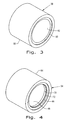
Fig. 3 shows a perspective view of a track bushing embodying the present invention; and -
Fig. 4 shows a perspective view of another track bushing embodying another form of the present invention. - Corresponding reference characters indicate corresponding parts throughout the several views. The exemplifications set out herein illustrate embodiments of the invention and such exemplifications are not to be construed as limiting the scope of the invention in any manner.
- Referring now to the drawings, and more particularly to
Fig. 1 there is shown anendless track assembly 10 used in a work machine (not shown). Theendless track assembly 10 includes, among other mechanisms, adrive sprocket 12 used to power theendless track assembly 10 in a continuous loop throughdrive teeth 14. Theendless track 16 is driven by theteeth 14 and provides support for a plurality ofshoes 18, (only two of which are shown,) that engage the ground. Theshoes 18 are removably fastened to theendless track 10 byappropriate fasteners 20. - As specifically shown in
Fig. 2 , theendless tracks 16 includelinks center sections Holes shoes 18 tolinks Link 22 has anouter section 34 connected to thecenter section 26. In corresponding fashion,link 28 has anouter section 36 fastened tocenter section 28.Link 26 has aninner section 38 that overlaps the adjacentouter section 34 ofadjacent link 22. In like fashion,link 28 has aninner section 40 that overlaps withouter end section 36 of theadjacent link 24. - The
links track pins 42.Track pins 42 are received withinbores outer end sections pin pins 42 each have awear sleeve 48 fixed to and positioned over thepin 42. Wearsleeves 48 are received withinbores inner end portions - In accordance with the present invention, the track bushings 54 or 56 are employed to greatly increase the longevity of the
endless track assembly 10. Referring specifically toFig. 3 , track bushing 56 includes asteel sleeve 58 having sufficient thickness and strength to resist impact loads imposed during operation by theteeth 14 ofsprocket 12. Preferably,steel sleeve 58 may be formed from SAE 4050 steel hardened to 50 - 55 HRC. It should be apparent however, that other high-strength steel materials may be employed for this purpose.Steel sleeve 58 forms an outer sleeve and an inner sleeve is formed of a composite bearing 60.Composite bearing 60 is fixed to the inside ofsteel sleeve 58, either by press fitting or by bonding.Composite bearing 60 has aninternal diameter 62 that is sized to permit rotating movement relative to wearsleeve 48.Composite bearing 60 may be formed from composite bearing material having Teflon fibers and resin in and adjacentinternal diameter 62 to provide superior lubricity. While these bearings may be available from many different sources, one source is found under the brand name Polylube IFR backed bearing. - Referring to
Fig. 4 , analternate track bushing 54 is illustrated. This track bushing 54 includes an outer high-strength steel sleeve 64 with properties like those ofsleeve 58. Acomposite bearing 66 is fixed to the interior ofouter sleeve 64 and has aninternal diameter 68 sized to be received overwear sleeve 48 oftrack pin 42.Composite bearing 66 has properties like those ofcomposite bearing 60 but has a pair ofseals 70 received inannular grooves 72 adjacent the ends ofinternal diameter 68.Seals 70 may be formed from appropriate sealing material. - In operation,
track bushing 56 is positioned overwear sleeve 48 and, because ofcomposite bearing 60, is free to rotate onwear sleeve 48. This enables greatly increased service life. However, thecomposite bearing 60 has internal lubricity and is substantially less likely to seize or have premature failure than previous arrangements of lubricated bearings. Becausecomposite bearing 60 has internal lubricity, it is far less likely to have a harmful effect on its ability to function in the dirt and debris laden environment typically experienced by the endless track. In like manner, thetrack bushing 54 has the same resistance to outside contaminants but has the added protection of theseals 70 preventing ingress of contaminants to the area between thecomposite bearing 66 and thewear sleeve 48. - While this invention has been described with respect to at least one embodiment, the present invention can be further modified within the spirit and scope of this disclosure. This application is therefore intended to cover any variations, uses, or adaptations of the invention using its general principles. Further, this application is intended to cover such departures from the present disclosure as come within known or customary practice in the art to which this invention pertains and which fall within the limits of the appended claims.
Claims (10)
- A track bushing (54, 56) for an endless track (10) of a track type work machine, said bushing (54, 56) comprising:- an outer steel sleeve (58, 64) with sufficient thickness and strength to resist impact loading when in use; and- an inner sleeve formed from composite bearing material fixed to the outer steel sleeve (58, 64) and having an internal diameter (62, 68) sized to permit rotation of said track bushing relative to a pin component of the endless track (10) over which said track bushing (54, 56) is positioned.
- The track bushing (54, 56) as claimed in claim 1, wherein the inner sleeve is bonded to said outer sleeve (58, 64).
- The track (54, 56) bushing as claimed in claim 1, wherein the inner sleeve is press fit into the outer sleeve (58, 64) to fix it in place.
- The track bushing (54, 56) as claimed in claim 1, further comprising inner seals (70) on the inner diameter (62, 68) of said inner sleeve adjacent the ends thereof.
- The track bushing (54, 56) as claimed in claim 1, wherein the inner sleeve is formed from a composite bearing material having Teflon fibers and resin in and adjacent the internal diameter (62, 68) of said inner sleeve.
- The track bushing (54, 56) as claimed in claim 1, wherein the outer steel sleeve (58, 64) is formed from SAE 4050 steel hardened to approximately 50-55 HRC.
- The track bushing (54, 56) as claimed in claim 6, wherein the inner sleeve is formed from a composite bearing material having Teflon fibers and resin adjacent its internal diameter (62, 68).
- An endless track (10) for a track type work machine, said endless track (10) comprising:- a plurality of track links arranged end to end forming an endless track (10);- a plurality of track pins (42) for pivotally inner connecting said links and having an outer wear surface; and- a track bushing positioned over and coaxial with each pin (42), said track bushing according to any of the previous claims.
- The endless track (10) as claimed in claim 8, further comprising a sleeve (48) fixed over said pin (42) and providing the wear surface exposed to the internal diameter (62, 68) of said composite bearing material.
- The endless track (10) as claimed in claim 8, further comprising a sprocket (12) for engaging said plurality of track bushings (54, 56) and driving the endless track (10), said sprocket (12) impacting and driving the outer diameter of the outer steel sleeve of said track bushing (10).
Applications Claiming Priority (1)
| Application Number | Priority Date | Filing Date | Title |
|---|---|---|---|
| US201462022043P | 2014-07-08 | 2014-07-08 |
Publications (1)
| Publication Number | Publication Date |
|---|---|
| EP2965973A1 true EP2965973A1 (en) | 2016-01-13 |
Family
ID=53871821
Family Applications (1)
| Application Number | Title | Priority Date | Filing Date |
|---|---|---|---|
| EP15175115.3A Withdrawn EP2965973A1 (en) | 2014-07-08 | 2015-07-02 | Track bushing for endless track |
Country Status (3)
| Country | Link |
|---|---|
| US (1) | US10322759B2 (en) |
| EP (1) | EP2965973A1 (en) |
| BR (1) | BR102015016456B1 (en) |
Families Citing this family (3)
| Publication number | Priority date | Publication date | Assignee | Title |
|---|---|---|---|---|
| US11130532B2 (en) * | 2018-09-04 | 2021-09-28 | Caterpillar Inc. | Track joint assembly and track link having wear band structured for anti-scalloping |
| US11524733B2 (en) * | 2019-08-07 | 2022-12-13 | Caterpillar Inc. | Track assembly bushing having while iron member |
| CN118953524A (en) * | 2024-10-17 | 2024-11-15 | 浙江智臻机械制造有限公司 | A crawler frame for mining tunneling machine |
Citations (5)
| Publication number | Priority date | Publication date | Assignee | Title |
|---|---|---|---|---|
| US4892365A (en) * | 1988-05-04 | 1990-01-09 | Szakacs Geza C | Track unit for use in a vehicle track assembly |
| EP1258419A1 (en) * | 2000-12-22 | 2002-11-20 | Hitachi Construction Machinery Co., Ltd. | Crawler |
| EP1591350A2 (en) * | 2004-04-27 | 2005-11-02 | Intertractor GmbH | Track for tracklaying vehicles |
| EP2114756A1 (en) * | 2007-01-30 | 2009-11-11 | Berco S.p.A. | Track joint seal system |
| JP2012116363A (en) * | 2010-12-01 | 2012-06-21 | Komatsu Ltd | Crawler bush and crawler link device |
Family Cites Families (16)
| Publication number | Priority date | Publication date | Assignee | Title |
|---|---|---|---|---|
| US2553646A (en) | 1947-08-11 | 1951-05-22 | Field Eric | Endless track or chain |
| US3218107A (en) * | 1962-04-02 | 1965-11-16 | Caterpillar Tractor Co | Seal and coupling assembly for a hinged joint |
| US3158923A (en) * | 1962-04-02 | 1964-12-01 | Caterpillar Tractor Co | Method for making a seal and coupling assembly |
| US3545005A (en) * | 1965-09-24 | 1970-12-01 | Cornelius A Gallagher | Hotbox detector |
| US5755495A (en) * | 1996-09-13 | 1998-05-26 | Industrial Fluid Technologies, Inc. | Bearing for snowmobile track |
| JP3683060B2 (en) | 1996-12-13 | 2005-08-17 | 株式会社小松製作所 | Tracked vehicle tracked vehicle |
| US6082721A (en) * | 1998-03-18 | 2000-07-04 | Kingsley; Richard J. | Bushing |
| US6145941A (en) | 1999-01-13 | 2000-11-14 | Caterpillar Inc. | Track bushing having improved abrasion and galling resistance |
| US6846051B2 (en) * | 2000-08-21 | 2005-01-25 | Caterpillar Inc | Joint assembly to resist galling |
| JP4282284B2 (en) | 2001-08-22 | 2009-06-17 | 株式会社小松製作所 | Track |
| US9616951B2 (en) | 2002-03-06 | 2017-04-11 | Deere & Company | Non-carburized components of track-type machines having a metallurgically bonded coating |
| CA2552119C (en) * | 2006-07-12 | 2012-07-10 | Jean Despres | Endless track suspension |
| US8100483B2 (en) * | 2007-10-18 | 2012-01-24 | Caterpillar Inc. | Machine and track assembly for use therewith |
| CA2688802A1 (en) * | 2008-11-28 | 2010-05-28 | David Brian Magnus | Bearing assembly comprising woven synthetic fibres |
| IT1393533B1 (en) * | 2009-03-24 | 2012-04-27 | Berco Spa | ROTARY BUSH CHAIN FOR TRACKED VEHICLES WITH IMPROVED STRIPED BEARINGS |
| US20110005876A1 (en) * | 2009-07-10 | 2011-01-13 | Scott Jenkinson | Drum wear indicator |
-
2015
- 2015-07-02 EP EP15175115.3A patent/EP2965973A1/en not_active Withdrawn
- 2015-07-08 US US14/794,219 patent/US10322759B2/en active Active
- 2015-07-08 BR BR102015016456-4A patent/BR102015016456B1/en not_active IP Right Cessation
Patent Citations (5)
| Publication number | Priority date | Publication date | Assignee | Title |
|---|---|---|---|---|
| US4892365A (en) * | 1988-05-04 | 1990-01-09 | Szakacs Geza C | Track unit for use in a vehicle track assembly |
| EP1258419A1 (en) * | 2000-12-22 | 2002-11-20 | Hitachi Construction Machinery Co., Ltd. | Crawler |
| EP1591350A2 (en) * | 2004-04-27 | 2005-11-02 | Intertractor GmbH | Track for tracklaying vehicles |
| EP2114756A1 (en) * | 2007-01-30 | 2009-11-11 | Berco S.p.A. | Track joint seal system |
| JP2012116363A (en) * | 2010-12-01 | 2012-06-21 | Komatsu Ltd | Crawler bush and crawler link device |
Also Published As
| Publication number | Publication date |
|---|---|
| US20160009324A1 (en) | 2016-01-14 |
| US10322759B2 (en) | 2019-06-18 |
| BR102015016456B1 (en) | 2022-06-21 |
| BR102015016456A2 (en) | 2017-12-05 |
Similar Documents
| Publication | Publication Date | Title |
|---|---|---|
| EP2583883B1 (en) | Track Chain Joint for a Crawler Type Work Vehicle | |
| CN101723006B (en) | Dual-bushing track chain cartridge | |
| KR101698620B1 (en) | Track with rotating bushings for track-type vehicles | |
| US20120146397A1 (en) | Roller unit | |
| US8113597B2 (en) | Track joint seal system | |
| US9745005B2 (en) | Roller assembly for a track-type machine | |
| CN107922023B (en) | Lubricating Cores for Hydraulic Mining Shovel Tracks | |
| KR102629734B1 (en) | Sealing system for tracks | |
| KR20110129962A (en) | Track with rotary bushing for track-type vehicles with improved sliding bearing | |
| US10322759B2 (en) | Track bushing for endless track | |
| US20180319448A1 (en) | Curved track pad ribs for a track chain | |
| US9656707B2 (en) | High speed metal face seal | |
| US11702157B2 (en) | Roller path of a track pad for a track chain | |
| KR102629721B1 (en) | Track joint assembly of machine tracks with pin stops for securing cartridge pins | |
| AU2011349602B2 (en) | Seal assembly | |
| KR102681583B1 (en) | A cartridge pin assembly including a sleeve bearing having a flared end, and a track chain assembly including the cartridge pin assembly. | |
| KR102744215B1 (en) | Grease bearing track | |
| JP2023505793A (en) | A track joint assembly for a ground engaging track with a track pin having an enlarged central section | |
| WO2016048778A1 (en) | Greased hydraulic excavator track seal assembly | |
| US20150197293A1 (en) | Track joint assemblies | |
| US10889342B2 (en) | Contoured double pass roller path for a track chain | |
| US20200032911A1 (en) | Metal Face Seal With Exclusion System |
Legal Events
| Date | Code | Title | Description |
|---|---|---|---|
| PUAI | Public reference made under article 153(3) epc to a published international application that has entered the european phase |
Free format text: ORIGINAL CODE: 0009012 |
|
| AK | Designated contracting states |
Kind code of ref document: A1 Designated state(s): AL AT BE BG CH CY CZ DE DK EE ES FI FR GB GR HR HU IE IS IT LI LT LU LV MC MK MT NL NO PL PT RO RS SE SI SK SM TR |
|
| AX | Request for extension of the european patent |
Extension state: BA ME |
|
| STAA | Information on the status of an ep patent application or granted ep patent |
Free format text: STATUS: THE APPLICATION HAS BEEN WITHDRAWN |
|
| 18W | Application withdrawn |
Effective date: 20160714 |