EP2964928B1 - Non-contacting seals for geared gas turbine engine bearing compartments - Google Patents
Non-contacting seals for geared gas turbine engine bearing compartments Download PDFInfo
- Publication number
- EP2964928B1 EP2964928B1 EP14759956.7A EP14759956A EP2964928B1 EP 2964928 B1 EP2964928 B1 EP 2964928B1 EP 14759956 A EP14759956 A EP 14759956A EP 2964928 B1 EP2964928 B1 EP 2964928B1
- Authority
- EP
- European Patent Office
- Prior art keywords
- seal
- gas turbine
- turbine engine
- set forth
- face
- Prior art date
- Legal status (The legal status is an assumption and is not a legal conclusion. Google has not performed a legal analysis and makes no representation as to the accuracy of the status listed.)
- Active
Links
Images
Classifications
-
- F—MECHANICAL ENGINEERING; LIGHTING; HEATING; WEAPONS; BLASTING
- F01—MACHINES OR ENGINES IN GENERAL; ENGINE PLANTS IN GENERAL; STEAM ENGINES
- F01D—NON-POSITIVE DISPLACEMENT MACHINES OR ENGINES, e.g. STEAM TURBINES
- F01D25/00—Component parts, details, or accessories, not provided for in, or of interest apart from, other groups
- F01D25/18—Lubricating arrangements
- F01D25/183—Sealing means
- F01D25/186—Sealing means for sliding contact bearing
-
- F—MECHANICAL ENGINEERING; LIGHTING; HEATING; WEAPONS; BLASTING
- F01—MACHINES OR ENGINES IN GENERAL; ENGINE PLANTS IN GENERAL; STEAM ENGINES
- F01D—NON-POSITIVE DISPLACEMENT MACHINES OR ENGINES, e.g. STEAM TURBINES
- F01D11/00—Preventing or minimising internal leakage of working-fluid, e.g. between stages
- F01D11/02—Preventing or minimising internal leakage of working-fluid, e.g. between stages by non-contact sealings, e.g. of labyrinth type
-
- F—MECHANICAL ENGINEERING; LIGHTING; HEATING; WEAPONS; BLASTING
- F01—MACHINES OR ENGINES IN GENERAL; ENGINE PLANTS IN GENERAL; STEAM ENGINES
- F01D—NON-POSITIVE DISPLACEMENT MACHINES OR ENGINES, e.g. STEAM TURBINES
- F01D25/00—Component parts, details, or accessories, not provided for in, or of interest apart from, other groups
- F01D25/16—Arrangement of bearings; Supporting or mounting bearings in casings
- F01D25/166—Sliding contact bearing
- F01D25/168—Sliding contact bearing for axial load mainly
-
- F—MECHANICAL ENGINEERING; LIGHTING; HEATING; WEAPONS; BLASTING
- F01—MACHINES OR ENGINES IN GENERAL; ENGINE PLANTS IN GENERAL; STEAM ENGINES
- F01D—NON-POSITIVE DISPLACEMENT MACHINES OR ENGINES, e.g. STEAM TURBINES
- F01D25/00—Component parts, details, or accessories, not provided for in, or of interest apart from, other groups
- F01D25/18—Lubricating arrangements
- F01D25/22—Lubricating arrangements using working-fluid or other gaseous fluid as lubricant
-
- F—MECHANICAL ENGINEERING; LIGHTING; HEATING; WEAPONS; BLASTING
- F02—COMBUSTION ENGINES; HOT-GAS OR COMBUSTION-PRODUCT ENGINE PLANTS
- F02C—GAS-TURBINE PLANTS; AIR INTAKES FOR JET-PROPULSION PLANTS; CONTROLLING FUEL SUPPLY IN AIR-BREATHING JET-PROPULSION PLANTS
- F02C7/00—Features, components parts, details or accessories, not provided for in, or of interest apart form groups F02C1/00 - F02C6/00; Air intakes for jet-propulsion plants
- F02C7/28—Arrangement of seals
-
- F—MECHANICAL ENGINEERING; LIGHTING; HEATING; WEAPONS; BLASTING
- F16—ENGINEERING ELEMENTS AND UNITS; GENERAL MEASURES FOR PRODUCING AND MAINTAINING EFFECTIVE FUNCTIONING OF MACHINES OR INSTALLATIONS; THERMAL INSULATION IN GENERAL
- F16C—SHAFTS; FLEXIBLE SHAFTS; ELEMENTS OR CRANKSHAFT MECHANISMS; ROTARY BODIES OTHER THAN GEARING ELEMENTS; BEARINGS
- F16C32/00—Bearings not otherwise provided for
- F16C32/06—Bearings not otherwise provided for with moving member supported by a fluid cushion formed, at least to a large extent, otherwise than by movement of the shaft, e.g. hydrostatic air-cushion bearings
- F16C32/0629—Bearings not otherwise provided for with moving member supported by a fluid cushion formed, at least to a large extent, otherwise than by movement of the shaft, e.g. hydrostatic air-cushion bearings supported by a liquid cushion, e.g. oil cushion
- F16C32/0633—Bearings not otherwise provided for with moving member supported by a fluid cushion formed, at least to a large extent, otherwise than by movement of the shaft, e.g. hydrostatic air-cushion bearings supported by a liquid cushion, e.g. oil cushion the liquid being retained in a gap
-
- F—MECHANICAL ENGINEERING; LIGHTING; HEATING; WEAPONS; BLASTING
- F16—ENGINEERING ELEMENTS AND UNITS; GENERAL MEASURES FOR PRODUCING AND MAINTAINING EFFECTIVE FUNCTIONING OF MACHINES OR INSTALLATIONS; THERMAL INSULATION IN GENERAL
- F16C—SHAFTS; FLEXIBLE SHAFTS; ELEMENTS OR CRANKSHAFT MECHANISMS; ROTARY BODIES OTHER THAN GEARING ELEMENTS; BEARINGS
- F16C33/00—Parts of bearings; Special methods for making bearings or parts thereof
- F16C33/72—Sealings
-
- F—MECHANICAL ENGINEERING; LIGHTING; HEATING; WEAPONS; BLASTING
- F16—ENGINEERING ELEMENTS AND UNITS; GENERAL MEASURES FOR PRODUCING AND MAINTAINING EFFECTIVE FUNCTIONING OF MACHINES OR INSTALLATIONS; THERMAL INSULATION IN GENERAL
- F16J—PISTONS; CYLINDERS; SEALINGS
- F16J15/00—Sealings
- F16J15/16—Sealings between relatively-moving surfaces
- F16J15/34—Sealings between relatively-moving surfaces with slip-ring pressed against a more or less radial face on one member
- F16J15/3404—Sealings between relatively-moving surfaces with slip-ring pressed against a more or less radial face on one member and characterised by parts or details relating to lubrication, cooling or venting of the seal
- F16J15/3408—Sealings between relatively-moving surfaces with slip-ring pressed against a more or less radial face on one member and characterised by parts or details relating to lubrication, cooling or venting of the seal at least one ring having an uneven slipping surface
- F16J15/3412—Sealings between relatively-moving surfaces with slip-ring pressed against a more or less radial face on one member and characterised by parts or details relating to lubrication, cooling or venting of the seal at least one ring having an uneven slipping surface with cavities
- F16J15/342—Sealings between relatively-moving surfaces with slip-ring pressed against a more or less radial face on one member and characterised by parts or details relating to lubrication, cooling or venting of the seal at least one ring having an uneven slipping surface with cavities with means for feeding fluid directly to the face
-
- F—MECHANICAL ENGINEERING; LIGHTING; HEATING; WEAPONS; BLASTING
- F16—ENGINEERING ELEMENTS AND UNITS; GENERAL MEASURES FOR PRODUCING AND MAINTAINING EFFECTIVE FUNCTIONING OF MACHINES OR INSTALLATIONS; THERMAL INSULATION IN GENERAL
- F16J—PISTONS; CYLINDERS; SEALINGS
- F16J15/00—Sealings
- F16J15/44—Free-space packings
- F16J15/441—Free-space packings with floating ring
-
- F—MECHANICAL ENGINEERING; LIGHTING; HEATING; WEAPONS; BLASTING
- F05—INDEXING SCHEMES RELATING TO ENGINES OR PUMPS IN VARIOUS SUBCLASSES OF CLASSES F01-F04
- F05D—INDEXING SCHEME FOR ASPECTS RELATING TO NON-POSITIVE-DISPLACEMENT MACHINES OR ENGINES, GAS-TURBINES OR JET-PROPULSION PLANTS
- F05D2220/00—Application
- F05D2220/30—Application in turbines
- F05D2220/32—Application in turbines in gas turbines
-
- F—MECHANICAL ENGINEERING; LIGHTING; HEATING; WEAPONS; BLASTING
- F05—INDEXING SCHEMES RELATING TO ENGINES OR PUMPS IN VARIOUS SUBCLASSES OF CLASSES F01-F04
- F05D—INDEXING SCHEME FOR ASPECTS RELATING TO NON-POSITIVE-DISPLACEMENT MACHINES OR ENGINES, GAS-TURBINES OR JET-PROPULSION PLANTS
- F05D2240/00—Components
- F05D2240/50—Bearings
-
- F—MECHANICAL ENGINEERING; LIGHTING; HEATING; WEAPONS; BLASTING
- F16—ENGINEERING ELEMENTS AND UNITS; GENERAL MEASURES FOR PRODUCING AND MAINTAINING EFFECTIVE FUNCTIONING OF MACHINES OR INSTALLATIONS; THERMAL INSULATION IN GENERAL
- F16C—SHAFTS; FLEXIBLE SHAFTS; ELEMENTS OR CRANKSHAFT MECHANISMS; ROTARY BODIES OTHER THAN GEARING ELEMENTS; BEARINGS
- F16C2360/00—Engines or pumps
- F16C2360/23—Gas turbine engines
-
- Y—GENERAL TAGGING OF NEW TECHNOLOGICAL DEVELOPMENTS; GENERAL TAGGING OF CROSS-SECTIONAL TECHNOLOGIES SPANNING OVER SEVERAL SECTIONS OF THE IPC; TECHNICAL SUBJECTS COVERED BY FORMER USPC CROSS-REFERENCE ART COLLECTIONS [XRACs] AND DIGESTS
- Y02—TECHNOLOGIES OR APPLICATIONS FOR MITIGATION OR ADAPTATION AGAINST CLIMATE CHANGE
- Y02T—CLIMATE CHANGE MITIGATION TECHNOLOGIES RELATED TO TRANSPORTATION
- Y02T50/00—Aeronautics or air transport
- Y02T50/60—Efficient propulsion technologies, e.g. for aircraft
Definitions
- Gas turbine engines are known and, when utilized in aircraft applications, typically include a fan delivering air into a bypass duct and into a core engine flow.
- the core engine flow passes into a compressor where the air is compressed and then delivered into a combustion section.
- the air is mixed with fuel in the combustion section and ignited. Products of that combustion pass downstream over turbine rotors, driving them to rotate.
- a fan drive turbine drove the fan through a direct drive, such that they rotated at the same speed. This restricted the speed available for the fan drive turbine, as the fan speed was limited.
- US 2012/0280458 A1 discloses a prior art gas turbine engine.
- WO 2013/180762 A1 which is prior art under Article 54(3) EPC only, discloses a thrust balance system for a gas turbine engine.
- the rotating element is a shaft rotating with a rotor having an axial face facing the seal face.
- a grooved area is formed in one of the faces, with the grooved area having a plurality of circumferentially spaced grooves generating hydrodynamic lift-off forces and allowing leakage of pressurized air across the faces and into the bearing compartment.
- the grooved area resists leakage of lubricant from the bearing compartment.
- the grooved area is formed in the rotor.
- the seal is formed with a plurality of passages to allow tapping of additional pressurized air to be delivered to the faces at a location in the proximity of the grooved area for generating hydrostatic lift-off forces.
- the seal face faces radially inwardly.
- the seal is a circumferentially segmented carbon seal.
- the rotating element is a shaft rotating with a rotor having a circumferential face facing the seal face.
- a grooved area is formed in one of the faces.
- the grooved area has a plurality of circumferentially spaced grooves for generating hydrodynamic lift-off forces and allowing leakage of pressurized air across the seal face and into the bearing compartment to resist leakage of lubricant from the bearing compartment.
- the seal is a controlled gap carbon seal having a full hoop seal and a metal band shrunk fit onto the seal, and positioned in a seal carrier.
- the seal is a carbon seal.
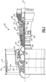
- FIG. 1 schematically illustrates a gas turbine engine 20.
- the gas turbine engine 20 is disclosed herein as a two-spool turbofan that generally incorporates a fan section 22, a compressor section 24, a combustor section 26 and a turbine section 28.
- Alternative engines might include an augmentor section (not shown) among other systems or features.
- the fan section 22 drives air along a bypass flow path B in a bypass duct defined within a nacelle 15, while the compressor section 24 drives air along a core flow path C for compression and communication into the combustor section 26 then expansion through the turbine section 28.
- the exemplary engine 20 generally includes a low speed spool 30 and a high speed spool 32 mounted for rotation about an engine central longitudinal axis A relative to an engine static structure 36 via several bearing systems 38. It should be understood that various bearing systems 38 at various locations may alternatively or additionally be provided, and the location of bearing systems 38 may be varied as appropriate to the application.
- the low speed spool 30 generally includes an inner shaft 40 that interconnects a fan 42, a low pressure compressor 44 and a low pressure turbine 46.
- the inner shaft 40 is connected to the fan 42 through a speed change mechanism, which in exemplary gas turbine engine 20 is illustrated as a geared architecture 48 to drive the fan 42 at a lower speed than the low speed spool 30.
- the high speed spool 32 includes an outer shaft 50 that interconnects a high pressure compressor 52 and high pressure turbine 54.
- a combustor 56 is arranged in exemplary gas turbine 20 between the high pressure compressor 52 and the high pressure turbine 54.
- a mid-turbine frame 57 of the engine static structure 36 is arranged generally between the high pressure turbine 54 and the low pressure turbine 46.
- the mid-turbine frame 57 further supports bearing systems 38 in the turbine section 28.
- the inner shaft 40 and the outer shaft 50 are concentric and rotate via bearing systems 38 about the engine central longitudinal axis A which is collinear with their longitudinal axes.
- the core airflow is compressed by the low pressure compressor 44 then the high pressure compressor 52, mixed and burned with fuel in the combustor 56, then expanded over the high pressure turbine 54 and low pressure turbine 46.
- the mid-turbine frame 57 includes airfoils 59 which are in the core airflow path C.
- the turbines 46, 54 rotationally drive the respective low speed spool 30 and high speed spool 32 in response to the expansion.
- each of the positions of the fan section 22, compressor section 24, combustor section 26, turbine section 28, and geared architecture 48 may be varied.
- geared architecture 48 may be located aft of combustor section 26 or even aft of turbine section 28, and fan section 22 may be positioned forward or aft of the location of geared architecture 48.
- the engine 20 in one example is a high-bypass geared aircraft engine.
- the engine 20 bypass ratio is greater than about six (6), with an example embodiment being greater than about ten (10)
- the geared architecture 48 is an epicyclic gear train, such as a planetary gear system or other gear system, with a gear reduction ratio of greater than about 2.3 and the low pressure turbine 46 has a pressure ratio that is greater than about five.
- the engine 20 bypass ratio is greater than about ten (10:1)
- the fan diameter is significantly larger than that of the low pressure compressor 44
- the low pressure turbine 46 has a pressure ratio that is greater than about five (5:1).
- Low pressure turbine 46 pressure ratio is pressure measured prior to inlet of low pressure turbine 46 as related to the pressure at the outlet of the low pressure turbine 46 prior to an exhaust nozzle.
- the geared architecture 48 may be an epicyclic gear train, such as a planetary gear system or other gear system, with a gear reduction ratio of greater than about 2.3:1. It should be understood, however, that the above parameters are only exemplary of one embodiment of a geared architecture engine.
- the fan section 22 of the engine 20 is designed for a particular flight condition -- typically cruise at about 0.8 Mach and about 35,000 feet.
- the flight condition of 0.8 Mach and 35,000 ft, with the engine at its best fuel consumption - also known as "bucket cruise Thrust Specific Fuel Consumption ('TSFC')" - is the industry standard parameter of lbm of fuel being burned divided by lbf of thrust the engine produces at that minimum point.
- "Low fan pressure ratio” is the pressure ratio across the fan blade alone, without a Fan Exit Guide Vane (“FEGV”) system.
- the low fan pressure ratio as disclosed herein according to one non-limiting embodiment is less than about 1.45.
- Low corrected fan tip speed is the actual fan tip speed in ft/sec divided by an industry standard temperature correction of [(Tram °R) / (518.7 °R)] 0.5 .
- the "Low corrected fan tip speed” as disclosed herein according to one non-limiting embodiment is less than about 1150 ft / second.
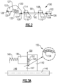
- FIG 2 shows an embodiment of an arrangement of bearing compartments 100 associated with the gas turbine engine, such as the gas turbine engine 20 illustrated in Figure 1 .
- a bearing compartment 102 is associated with a low speed shaft 92 at a location associated with the low pressure turbine.
- Bearings 106 are shown schematically as is a seal 104.
- a bearing compartment 108 is associated with a high speed rotor 90 and at the high pressure turbine of Figure 1 .
- Bearing compartment 108 includes seals 110 at each axial end and a central bearing 112.
- Another bearing compartment 114 is also associated with the high speed rotor 90 and the high pressure compressor and includes a bearing 118 and seals 116.
- a bearing compartment is associated with a fan drive gear system 122 at location 120 and with and the fan at location 123.
- Seals 126 and 128 mechanically seal the axial ends of the bearing compartment 120 and are associated with the fan rotor 127 and the low speed rotor 92.
- the seals 126, 128 are also respectively associated with the bearings 124 and 130 that are positioned within the bearing compartment 120/123.
- seals such as lift-off seals at any one or more of the locations of the seals shown in Figure 2 or in any other bearing compartment on a gas turbine engine.
- the seals may be lift-off seals and, more particularly, may be carbon lift-off seals.
- other non-contacting seals, including other lift-off seals may be used.
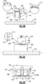
- a shaft 140 which in accordance with the invention is driven by a fan drive turbine rotating shaft in a gas turbine engine, has a mating rotor 142.
- An axial face 147 of this mating rotor 142 is sealed relative to a face 145 from a seal 144.
- the faces 145 and 147 face each other to form a mechanical seal.
- the seal 144 may be a non-contact seal such as a carbon seal lift-off seal.
- the interface between faces 145 and 147 experiences high velocities, especially when compared to the prior art.
- the high velocity is a combination of a high rotational speed of the shaft 140 and a relatively large diameter for the seal 144. Velocities greater than or equal to about 450 ft / second (137.16 meters / second) may be seen.
- seal 144 a set of shallow grooves 152 is provided by cutting into the face 147 of the rotor 142, as shown at circumferentially spaced grooves 154.
- a spring 146 biases the seal 144 toward the face 147.
- a higher pressure air is available in a chamber 148, which is on an opposed side of the seal 144 from the bearing compartment 150.
- the bearing compartment 150 is at a lower pressure than the chamber 148, and this higher pressure air passes through the grooved area 152, such that the air flow levitates (lifts-off) the sealing surface 145 of the non-rotating seal 144 from the sealing surface 147 of the rotor 142.
- the levitation is a result of hydrodynamic lifting force as the air passes into the bearing compartment 150, preventing oil from escaping the bearing compartment 150.
- Figure 3B provides the mechanical sealing between face 168 of a non-rotating seal 162 and a face 170 of a rotor in a manner somewhat similar to the Figure 3A embodiment.
- a grooved area 172 having circumferentially spaced grooves 174 with the features as described for the first embodiment that generate hydrodynamic lifting force as the gas passes from a high pressure chamber 160 into the bearing compartment 274.
- the non-rotating seal 162 has an inlet 166, a passage 164, and an outlet 180 which delivers additional high pressure air generating hydrostatic lifting forces at a radial location in the proximity of the grooved area 172, thereby providing a stronger and more stable lift-off seal compared to the first embodiment.
- the non-rotating seal 162, which is biased toward the rotor 170 by a spring 161 may be a carbon lift-off seal.
- Figure 3C shows another embodiment 182, wherein the seal 186 has a plurality of circumferentially segmented members biased by spring 184 toward a face 185 of a rotor 142 rotating with the shaft 140. Seal 186 has a radially inwardly facing face 183 providing the seal face with the mating face 185.
- One of the sealing faces either 183 or 185, has a set of shallow, circumferentially spaced grooves 210 in a grooved area 211, somewhat similar to those described in the earlier embodiments that generate a hydrodynamic force that levitates (lifts-off) the non-rotating sealing surface 183 from the rotating mating surface 185 when the high pressure chamber 188 delivers pressurized air across the seal 186 to prevent leakage of oil from the bearing compartment 190.
- Figure 3D shows an embodiment of a controlled gap non-contacting seal assembly 201.
- the shaft 140 has an outer surface spaced by a small gap 196 from two carbon seals 192.
- the gap is controlled by design, typically by sizing the sealing diameters of the seals 192 and the rotor 140 such that a small gap is maintained under all conditions.
- the shaft outer surface 193 and a radially inward facing surfaces 191 of the seals 192 provide the seal faces.
- the carbon seals 192 are full hoop members extending around the entire circumference of the shaft 140.
- a metal band 194 is shrunk fit onto the seal 192.
- a carrier 195 mounts the seals 192.
- a high pressure chamber 198 is spaced from the bearing compartment 200, such that high pressure air passes through the gap 196 to prevent the leakage of lubricant.
- All of the disclosed embodiments reduce the friction between the seal and the rotating components. This reduces heat generation due to friction, increases the durability of the seals, minimizes loss of oil, and increases the efficiency in fuel consumption of the overall engine. Moreover, as a result of the reduction in friction, less lubricant can be used, thereby also reducing the size of the applicable fluid storage tank (not shown) and the applicable cooling system fluid pumping apparatus (also not shown). Accordingly, the overall weight of the engine may be greatly reduced, thereby increasing the engine's fuel efficiency.
- the disclosed embodiments may be useful at any bearing compartment in a gas turbine engine. Although shafts are shown supported by the bearings, the disclosure would extend to other rotating elements supported by a bearing.
Landscapes
- Engineering & Computer Science (AREA)
- General Engineering & Computer Science (AREA)
- Mechanical Engineering (AREA)
- Chemical & Material Sciences (AREA)
- Combustion & Propulsion (AREA)
- Turbine Rotor Nozzle Sealing (AREA)
- Sealing Using Fluids, Sealing Without Contact, And Removal Of Oil (AREA)
- Rolling Contact Bearings (AREA)
Description
- Gas turbine engines are known and, when utilized in aircraft applications, typically include a fan delivering air into a bypass duct and into a core engine flow. The core engine flow passes into a compressor where the air is compressed and then delivered into a combustion section. The air is mixed with fuel in the combustion section and ignited. Products of that combustion pass downstream over turbine rotors, driving them to rotate.
- Historically, a fan drive turbine drove the fan through a direct drive, such that they rotated at the same speed. This restricted the speed available for the fan drive turbine, as the fan speed was limited.
- More recently, it has been proposed to include a gear reduction between the fan drive turbine and the fan. With this change, the speed of the fan drive turbine can increase.
- In gas turbine engines, there are a number of bearing compartments which are desirably sealed. In the prior art, operating at slower speeds, contact seals have been utilized, which directly contacted surfaces rotating with the shaft to seal the bearing compartments. Such contact seals were typically cooled using oil or other lubricant, which was circulated through a cooling system. For geared engines, in which certain components are enabled to rotate faster than corresponding components in non-geared engines, to achieve the same amount of cooling a larger volume of lubricant would be needed. Moreover, a larger volume of lubricant would require a larger holding tank and correspondingly larger cooling system fluid pumping apparatus. All of the larger volume of lubricant, the larger holding tank, and the larger fluid pumping apparatus would add undesirable weight to the engine.
-
US 2012/0280458 A1 discloses a prior art gas turbine engine. -
WO 2013/180762 A1 , which is prior art under Article 54(3) EPC only, discloses a thrust balance system for a gas turbine engine. - According to the present invention, there is provided a gas turbine engine as set forth in claim 1.
- In another embodiment according to any of the previous embodiments, the rotating element is a shaft rotating with a rotor having an axial face facing the seal face.
- In another embodiment according to any of the previous embodiments, a grooved area is formed in one of the faces, with the grooved area having a plurality of circumferentially spaced grooves generating hydrodynamic lift-off forces and allowing leakage of pressurized air across the faces and into the bearing compartment. The grooved area resists leakage of lubricant from the bearing compartment.
- In another embodiment according to any of the previous embodiments, the grooved area is formed in the rotor.
- In another embodiment according to any of the previous embodiments, the seal is formed with a plurality of passages to allow tapping of additional pressurized air to be delivered to the faces at a location in the proximity of the grooved area for generating hydrostatic lift-off forces.
- In another embodiment according to any of the previous embodiments, the seal face faces radially inwardly.
- In another embodiment according to any of the previous embodiments, the seal is a circumferentially segmented carbon seal.
- In another embodiment according to any of the previous embodiments, the rotating element is a shaft rotating with a rotor having a circumferential face facing the seal face.
- In another embodiment according to any of the previous embodiments, a grooved area is formed in one of the faces. The grooved area has a plurality of circumferentially spaced grooves for generating hydrodynamic lift-off forces and allowing leakage of pressurized air across the seal face and into the bearing compartment to resist leakage of lubricant from the bearing compartment.
- In another embodiment according to any of the previous embodiments, the seal is a controlled gap carbon seal having a full hoop seal and a metal band shrunk fit onto the seal, and positioned in a seal carrier.
- In another embodiment according to any of the previous embodiments, the seal is a carbon seal.
- These and other features may be best understood from the following drawings and specification.
-
-
Figure 1 schematically shows a gas turbine engine. -
Figure 2 schematically shows example locations of bearing compartments. -
Figure 3A is a first embodiment of a non-contact seal according to the present invention. -
Figure 3B shows a second embodiment of a non-contact seal according to the present invention. -
Figure 3C shows a third embodiment of a non-contact seal according to the present invention. -
Figure 3D shows a fourth embodiment of a non-contact seal assembly according to the present invention. -
Figure 1 schematically illustrates agas turbine engine 20. Thegas turbine engine 20 is disclosed herein as a two-spool turbofan that generally incorporates afan section 22, acompressor section 24, acombustor section 26 and aturbine section 28. Alternative engines might include an augmentor section (not shown) among other systems or features. Thefan section 22 drives air along a bypass flow path B in a bypass duct defined within anacelle 15, while thecompressor section 24 drives air along a core flow path C for compression and communication into thecombustor section 26 then expansion through theturbine section 28. Although depicted as a two-spool turbofan gas turbine engine in the disclosed non-limiting embodiment, it should be understood that the concepts described herein are not limited to use with two-spool turbofans as the teachings may be applied to other types of turbine engines including three-spool architectures. - The
exemplary engine 20 generally includes alow speed spool 30 and ahigh speed spool 32 mounted for rotation about an engine central longitudinal axis A relative to an enginestatic structure 36 viaseveral bearing systems 38. It should be understood thatvarious bearing systems 38 at various locations may alternatively or additionally be provided, and the location ofbearing systems 38 may be varied as appropriate to the application. - The
low speed spool 30 generally includes aninner shaft 40 that interconnects afan 42, a low pressure compressor 44 and alow pressure turbine 46. Theinner shaft 40 is connected to thefan 42 through a speed change mechanism, which in exemplarygas turbine engine 20 is illustrated as a gearedarchitecture 48 to drive thefan 42 at a lower speed than thelow speed spool 30. Thehigh speed spool 32 includes anouter shaft 50 that interconnects ahigh pressure compressor 52 andhigh pressure turbine 54. Acombustor 56 is arranged inexemplary gas turbine 20 between thehigh pressure compressor 52 and thehigh pressure turbine 54. Amid-turbine frame 57 of the enginestatic structure 36 is arranged generally between thehigh pressure turbine 54 and thelow pressure turbine 46. Themid-turbine frame 57 further supports bearingsystems 38 in theturbine section 28. Theinner shaft 40 and theouter shaft 50 are concentric and rotate viabearing systems 38 about the engine central longitudinal axis A which is collinear with their longitudinal axes. - The core airflow is compressed by the low pressure compressor 44 then the
high pressure compressor 52, mixed and burned with fuel in thecombustor 56, then expanded over thehigh pressure turbine 54 andlow pressure turbine 46. Themid-turbine frame 57 includesairfoils 59 which are in the core airflow path C. Theturbines low speed spool 30 andhigh speed spool 32 in response to the expansion. It will be appreciated that each of the positions of thefan section 22,compressor section 24,combustor section 26,turbine section 28, and gearedarchitecture 48 may be varied. For example, gearedarchitecture 48 may be located aft ofcombustor section 26 or even aft ofturbine section 28, andfan section 22 may be positioned forward or aft of the location of gearedarchitecture 48. - The
engine 20 in one example is a high-bypass geared aircraft engine. In a further example, theengine 20 bypass ratio is greater than about six (6), with an example embodiment being greater than about ten (10), the gearedarchitecture 48 is an epicyclic gear train, such as a planetary gear system or other gear system, with a gear reduction ratio of greater than about 2.3 and thelow pressure turbine 46 has a pressure ratio that is greater than about five. In one disclosed embodiment, theengine 20 bypass ratio is greater than about ten (10:1), the fan diameter is significantly larger than that of the low pressure compressor 44, and thelow pressure turbine 46 has a pressure ratio that is greater than about five (5:1).Low pressure turbine 46 pressure ratio is pressure measured prior to inlet oflow pressure turbine 46 as related to the pressure at the outlet of thelow pressure turbine 46 prior to an exhaust nozzle. The gearedarchitecture 48 may be an epicyclic gear train, such as a planetary gear system or other gear system, with a gear reduction ratio of greater than about 2.3:1. It should be understood, however, that the above parameters are only exemplary of one embodiment of a geared architecture engine. - A significant amount of thrust is provided by the bypass flow B due to the high bypass ratio. The
fan section 22 of theengine 20 is designed for a particular flight condition -- typically cruise at about 0.8 Mach and about 35,000 feet. The flight condition of 0.8 Mach and 35,000 ft, with the engine at its best fuel consumption - also known as "bucket cruise Thrust Specific Fuel Consumption ('TSFC')" - is the industry standard parameter of lbm of fuel being burned divided by lbf of thrust the engine produces at that minimum point. "Low fan pressure ratio" is the pressure ratio across the fan blade alone, without a Fan Exit Guide Vane ("FEGV") system. The low fan pressure ratio as disclosed herein according to one non-limiting embodiment is less than about 1.45. "Low corrected fan tip speed" is the actual fan tip speed in ft/sec divided by an industry standard temperature correction of [(Tram °R) / (518.7 °R)]0.5. The "Low corrected fan tip speed" as disclosed herein according to one non-limiting embodiment is less than about 1150 ft / second. -
Figure 2 shows an embodiment of an arrangement of bearingcompartments 100 associated with the gas turbine engine, such as thegas turbine engine 20 illustrated inFigure 1 . As shown, abearing compartment 102 is associated with alow speed shaft 92 at a location associated with the low pressure turbine.Bearings 106 are shown schematically as is aseal 104. - A
bearing compartment 108 is associated with ahigh speed rotor 90 and at the high pressure turbine ofFigure 1 .Bearing compartment 108 includesseals 110 at each axial end and acentral bearing 112. - Another
bearing compartment 114 is also associated with thehigh speed rotor 90 and the high pressure compressor and includes abearing 118 and seals 116. - Finally, a bearing compartment is associated with a fan
drive gear system 122 atlocation 120 and with and the fan atlocation 123.Seals bearing compartment 120 and are associated with thefan rotor 127 and thelow speed rotor 92. Theseals bearings bearing compartment 120/123. - There are challenges with sealing the bearing compartments in a geared turbofan engine. Accordingly, various arrangements disclosed herein relate to the use of non-contacting seals such as lift-off seals at any one or more of the locations of the seals shown in
Figure 2 or in any other bearing compartment on a gas turbine engine. In some embodiments, the seals may be lift-off seals and, more particularly, may be carbon lift-off seals. Of course, in other embodiments other non-contacting seals, including other lift-off seals may be used. - Thus, as shown in
Figure 3A , ashaft 140, which in accordance with the invention is driven by a fan drive turbine rotating shaft in a gas turbine engine, has amating rotor 142. Anaxial face 147 of thismating rotor 142 is sealed relative to aface 145 from a seal 144. The faces 145 and 147 face each other to form a mechanical seal. The seal 144 may be a non-contact seal such as a carbon seal lift-off seal. The interface betweenfaces shaft 140 and a relatively large diameter for the seal 144. Velocities greater than or equal to about 450 ft / second (137.16 meters / second) may be seen. - In the
Figure 3A embodiment seal 144, a set ofshallow grooves 152 is provided by cutting into theface 147 of therotor 142, as shown at circumferentially spacedgrooves 154. Aspring 146 biases the seal 144 toward theface 147. A higher pressure air is available in achamber 148, which is on an opposed side of the seal 144 from thebearing compartment 150. Thebearing compartment 150 is at a lower pressure than thechamber 148, and this higher pressure air passes through thegrooved area 152, such that the air flow levitates (lifts-off) thesealing surface 145 of the non-rotating seal 144 from the sealingsurface 147 of therotor 142. The levitation is a result of hydrodynamic lifting force as the air passes into thebearing compartment 150, preventing oil from escaping thebearing compartment 150. - Another embodiment is illustrated in
Figure 3B. Figure 3B provides the mechanical sealing betweenface 168 of anon-rotating seal 162 and aface 170 of a rotor in a manner somewhat similar to theFigure 3A embodiment. There is agrooved area 172 having circumferentially spacedgrooves 174 with the features as described for the first embodiment that generate hydrodynamic lifting force as the gas passes from ahigh pressure chamber 160 into thebearing compartment 274. Furthermore, thenon-rotating seal 162 has aninlet 166, apassage 164, and anoutlet 180 which delivers additional high pressure air generating hydrostatic lifting forces at a radial location in the proximity of thegrooved area 172, thereby providing a stronger and more stable lift-off seal compared to the first embodiment. As shown, there is a plurality of circumferentially spacedoutlets 180. Thenon-rotating seal 162, which is biased toward therotor 170 by aspring 161, may be a carbon lift-off seal. -
Figure 3C shows anotherembodiment 182, wherein theseal 186 has a plurality of circumferentially segmented members biased byspring 184 toward aface 185 of arotor 142 rotating with theshaft 140.Seal 186 has a radially inwardly facingface 183 providing the seal face with themating face 185. One of the sealing faces, either 183 or 185, has a set of shallow, circumferentially spacedgrooves 210 in agrooved area 211, somewhat similar to those described in the earlier embodiments that generate a hydrodynamic force that levitates (lifts-off) thenon-rotating sealing surface 183 from therotating mating surface 185 when thehigh pressure chamber 188 delivers pressurized air across theseal 186 to prevent leakage of oil from thebearing compartment 190. -
Figure 3D shows an embodiment of a controlled gapnon-contacting seal assembly 201. Theshaft 140 has an outer surface spaced by asmall gap 196 from two carbon seals 192. The gap is controlled by design, typically by sizing the sealing diameters of theseals 192 and therotor 140 such that a small gap is maintained under all conditions. The shaftouter surface 193 and a radially inward facingsurfaces 191 of theseals 192 provide the seal faces. In one embodiment, the carbon seals 192 are full hoop members extending around the entire circumference of theshaft 140. Ametal band 194 is shrunk fit onto theseal 192. Acarrier 195 mounts theseals 192. Ahigh pressure chamber 198 is spaced from thebearing compartment 200, such that high pressure air passes through thegap 196 to prevent the leakage of lubricant. - All of the disclosed embodiments reduce the friction between the seal and the rotating components. This reduces heat generation due to friction, increases the durability of the seals, minimizes loss of oil, and increases the efficiency in fuel consumption of the overall engine. Moreover, as a result of the reduction in friction, less lubricant can be used, thereby also reducing the size of the applicable fluid storage tank (not shown) and the applicable cooling system fluid pumping apparatus (also not shown). Accordingly, the overall weight of the engine may be greatly reduced, thereby increasing the engine's fuel efficiency.
- The disclosed embodiments may be useful at any bearing compartment in a gas turbine engine. Although shafts are shown supported by the bearings, the disclosure would extend to other rotating elements supported by a bearing.
- Although various embodiments of this invention have been disclosed, a worker of ordinary skill in this art would recognize that certain modifications would come within the scope of this invention. For that reason, the following claims should be studied to determine the true scope and content of this invention.
Claims (11)
- A gas turbine engine comprising:a compressor section (24), a combustor (26), and a turbine section (25), a rotating element (140) and at least one bearing compartment (150; 274; 190; 200) including a bearing (106, 112, 118, 124, 130) for supporting said rotating element (140), seals (144; 162; 186; 192) associated with each of two opposed axial ends on either axial side of said bearing (106, 112, 118, 124, 130) for resisting leakage of lubricant outwardly of said bearing compartment (150; 274; 190; 200) and for allowing pressurized air to flow from a chamber (148; 160; 188; 198) across said seals (144; 162; 186; 192) into the bearing compartment (150; 274; 190; 200); andsaid seals (144; 162; 186; 192) each having a seal face (145; 168; 183; 191) facing a rotating face (147; 170; 185; 193) rotating with said rotating element (140), and said seals (144; 162; 186; 192) each being a non-contact seal;whereinthe gas turbine engine further comprises a fan (22) and a fan drive turbine driving said fan (22) through a gear reduction, and in that the rotating element (140) is driven by the fan drive turbine, and said bearing compartment is associated with said gear reduction and with said fan (22).
- The gas turbine engine (20) as set forth in claim 1, wherein said rotating element (140) is a shaft rotating with a rotor (142) having an axial face (147; 170; 185; 193) facing said seal face (145; 168; 183; 191).
- The gas turbine engine (20) as set forth in claim 2, wherein a grooved area (152; 172; 211) is formed in one of said faces (147; 170; 185; 193), with said grooved area (152; 172; 211) having a plurality of circumferentially spaced grooves (154; 174; 210) for generating hydrodynamic lift-off forces and allowing leakage of pressurized air across said seal face (145; 168; 183; 191) and into the bearing compartment (150; 274; 190; 200) to resist leakage of lubricant from the bearing compartment (150; 274; 190; 200).
- The gas turbine engine (20) as set forth in claim 3, wherein said grooved area (152; 172; 211) is formed in said rotor (140).
- The gas turbine engine (20) as set forth in claim 3 or 4, wherein said seal (162) being formed with a plurality of passages (164) to allow tapping of additional pressurized air to be delivered to the faces (168, 170) at a location in the proximity of the grooved area (172) for generating hydrostatic lift-off forces.
- The gas turbine engine (20) as set forth in any preceding claim, wherein said seal (144; 162; 186; 192) is a carbon seal.
- The gas turbine engine as set forth in any preceding claim, wherein said seal face (145; 168; 183; 191) faces radially inwardly.
- The gas turbine engine as set forth in claim 7, wherein said seal (144; 162; 186; 192) is a circumferentially segmented carbon seal.
- The gas turbine engine (20) as set forth in claim 8, wherein said rotating element (140) is a shaft rotating with a rotor (142) having a circumferential face (147; 170; 185; 193) facing said seal face (145; 168; 183; 191).
- The gas turbine engine (20) as set forth in claim 9, wherein a grooved area (152; 172; 211) is formed in one of said faces (147; 170; 185; 193), with said grooved area (152; 172; 211) having a plurality of circumferentially spaced grooves (154; 174; 210) for generating hydrodynamic lift-off forces and allowing leakage of pressurized air across said seal face (145; 168; 183; 191) and into the bearing compartment (150; 274; 190; 200) to resist leakage of lubricant from the bearing compartment (150; 274; 190; 200).
- The gas turbine engine (20) as set forth in any of claims 7 to 10, wherein said seal (192) is a controlled gap carbon seal having a full hoop seal and a metal band (194) shrunk fit onto the seal, and positioned in a seal carrier (195).
Applications Claiming Priority (2)
| Application Number | Priority Date | Filing Date | Title |
|---|---|---|---|
| US13/787,919 US8641366B1 (en) | 2013-03-07 | 2013-03-07 | Non-contacting seals for geared gas turbine engine bearing compartments |
| PCT/US2014/020462 WO2014138143A1 (en) | 2013-03-07 | 2014-03-05 | Non-contacting seals for geared gas turbine engine bearing compartments |
Publications (3)
| Publication Number | Publication Date |
|---|---|
| EP2964928A1 EP2964928A1 (en) | 2016-01-13 |
| EP2964928A4 EP2964928A4 (en) | 2016-03-09 |
| EP2964928B1 true EP2964928B1 (en) | 2024-08-07 |
Family
ID=50001573
Family Applications (1)
| Application Number | Title | Priority Date | Filing Date |
|---|---|---|---|
| EP14759956.7A Active EP2964928B1 (en) | 2013-03-07 | 2014-03-05 | Non-contacting seals for geared gas turbine engine bearing compartments |
Country Status (3)
| Country | Link |
|---|---|
| US (4) | US8641366B1 (en) |
| EP (1) | EP2964928B1 (en) |
| WO (1) | WO2014138143A1 (en) |
Families Citing this family (17)
| Publication number | Priority date | Publication date | Assignee | Title |
|---|---|---|---|---|
| US10443443B2 (en) | 2013-03-07 | 2019-10-15 | United Technologies Corporation | Non-contacting seals for geared gas turbine engine bearing compartments |
| US8641366B1 (en) | 2013-03-07 | 2014-02-04 | United Technologies Corporation | Non-contacting seals for geared gas turbine engine bearing compartments |
| WO2014184603A1 (en) * | 2013-05-16 | 2014-11-20 | Dresser-Rand Sa | Bi-directional shaft seal |
| US20160003142A1 (en) | 2014-06-11 | 2016-01-07 | United Technologies Corporation | Geared turbofan with gearbox seal |
| US10502094B2 (en) * | 2014-07-22 | 2019-12-10 | United Technologies Corporation | Bearing compartment sealing system with passive cooling |
| CN104500743B (en) * | 2014-12-15 | 2016-06-01 | 中国燃气涡轮研究院 | Tightness system between a kind of reversion axle |
| GB201510719D0 (en) * | 2015-06-18 | 2015-08-05 | Rolls Royce Plc | Sealing element |
| US10196986B2 (en) | 2015-09-04 | 2019-02-05 | General Electric Company | Hydrodynamic seals in bearing compartments of gas turbine engines |
| US20170130732A1 (en) * | 2015-11-06 | 2017-05-11 | United Technologies Corporation | Compressor exit seal |
| US9909438B2 (en) | 2016-04-12 | 2018-03-06 | United Technologies Corporation | Hydrodynamic carbon face seal pressure booster |
| US10914195B2 (en) | 2016-04-18 | 2021-02-09 | General Electric Company | Rotary machine with gas bearings |
| US10247017B2 (en) * | 2016-06-29 | 2019-04-02 | General Electric Company | System and method for gas bearing support of turbine |
| EP3372793B1 (en) * | 2017-03-10 | 2020-05-13 | United Technologies Corporation | Non-contacting seals for geared gas turbine engine bearing compartments |
| US11078807B2 (en) | 2018-09-19 | 2021-08-03 | Borgwarner Inc. | Turbocharger and mating ring included therein |
| US11384772B2 (en) | 2018-09-19 | 2022-07-12 | Borgwarner Inc. | Rotating machine and mating ring included therein |
| US11920605B2 (en) | 2018-09-19 | 2024-03-05 | Borgwarner Inc. | Rotating machine and mating ring included therein |
| US11781481B2 (en) | 2021-06-11 | 2023-10-10 | Rtx Corporation | Oil circulation system for hybrid electric engine |
Citations (15)
| Publication number | Priority date | Publication date | Assignee | Title |
|---|---|---|---|---|
| EP0297381A1 (en) | 1987-07-03 | 1989-01-04 | Feodor Burgmann Dichtungswerke GmbH & Co. | Sealing arrangement for a shaft |
| US5107676A (en) * | 1989-07-21 | 1992-04-28 | Rolls-Royce Plc | Reduction gear assembly and a gas turbine engine |
| US5174584A (en) | 1991-07-15 | 1992-12-29 | General Electric Company | Fluid bearing face seal for gas turbine engines |
| US5619850A (en) | 1995-05-09 | 1997-04-15 | Alliedsignal Inc. | Gas turbine engine with bleed air buffer seal |
| US6142729A (en) | 1998-06-26 | 2000-11-07 | Techspace Aero | Sealing device for a turbomachine bearing chamber |
| US20020020967A1 (en) | 1995-04-20 | 2002-02-21 | Philippe Jacques Auber | Fail safe l-shaped spring carrier for gas seals |
| US7093418B2 (en) | 2004-04-21 | 2006-08-22 | Honeywell International, Inc. | Gas turbine engine including a low pressure sump seal buffer source and thermally isolated sump |
| US7175388B2 (en) | 2005-04-21 | 2007-02-13 | Pratt & Whitney Canada Corp. | Integrated labyrinth and carbon seal |
| EP1887199A2 (en) | 2006-07-31 | 2008-02-13 | General Electric Company | Gas turbine engine assembly |
| US20090314881A1 (en) | 2008-06-02 | 2009-12-24 | Suciu Gabriel L | Engine mount system for a turbofan gas turbine engine |
| US7726660B2 (en) | 2004-05-04 | 2010-06-01 | Rexnord Industries, Llc | Non-contacting seal for rotating surfaces |
| EP2362081A1 (en) | 2010-02-19 | 2011-08-31 | United Technologies Corporation | Bearing compartment pressurization and shaft ventilation system |
| EP2474711A2 (en) | 2011-01-10 | 2012-07-11 | United Technologies Corporation | Runner for circumferential seals |
| US20120280458A1 (en) | 2011-05-04 | 2012-11-08 | United Technologies Corporation | Hydrodynamic non-contacting seal |
| WO2013180762A1 (en) * | 2012-01-27 | 2013-12-05 | United Technologies Corporation | Thrust balance system for gas turbine engine |
Family Cites Families (20)
| Publication number | Priority date | Publication date | Assignee | Title |
|---|---|---|---|---|
| US3383033A (en) * | 1966-04-27 | 1968-05-14 | Gen Electric | Sealing means for axial flow compressor discharge |
| DE3447102A1 (en) * | 1984-12-22 | 1986-07-10 | MAN Gutehoffnungshütte GmbH, 4200 Oberhausen | HYDROSTATIC SHAFT SEAL OR HYDRODYNAMIC SHAFT SEAL |
| US5224714A (en) * | 1990-07-18 | 1993-07-06 | Ebara Corporation | Noncontacting face seal |
| US5284347A (en) * | 1991-03-25 | 1994-02-08 | General Electric Company | Gas bearing sealing means |
| CA2096759A1 (en) * | 1992-08-06 | 1994-02-07 | Mark G. Pospisil | Mechanical end face seal system |
| US6145843A (en) | 1998-10-19 | 2000-11-14 | Stein Seal Company | Hydrodynamic lift seal for use with compressible fluids |
| US8162322B2 (en) | 2006-10-25 | 2012-04-24 | Rexnord Industries, Llc | Hydrodynamic seal with circumferentially varying lift force |
| US8206083B2 (en) * | 2007-01-26 | 2012-06-26 | Stein Seal Company | Carbon hydrostatic face seal |
| US8109716B2 (en) * | 2007-08-17 | 2012-02-07 | United Technologies Corp. | Gas turbine engine systems involving hydrostatic face seals with anti-fouling provisioning |
| US20090051120A1 (en) * | 2007-08-23 | 2009-02-26 | United Technologies Corp. | Gas Turbine Engine Systems Involving Hydrostatic Face Seals |
| US9097350B2 (en) * | 2012-04-02 | 2015-08-04 | United Technologies Corporation | Axial non-contact seal |
| US8641366B1 (en) | 2013-03-07 | 2014-02-04 | United Technologies Corporation | Non-contacting seals for geared gas turbine engine bearing compartments |
| WO2015147967A1 (en) * | 2014-03-27 | 2015-10-01 | United Technologies Corporation | Gas turbine engine and seal assembly therefore |
| US20150285152A1 (en) * | 2014-04-03 | 2015-10-08 | United Technologies Corporation | Gas turbine engine and seal assembly therefore |
| US10167723B2 (en) * | 2014-06-06 | 2019-01-01 | United Technologies Corporation | Thermally isolated turbine section for a gas turbine engine |
| US20160003142A1 (en) * | 2014-06-11 | 2016-01-07 | United Technologies Corporation | Geared turbofan with gearbox seal |
| US10502094B2 (en) | 2014-07-22 | 2019-12-10 | United Technologies Corporation | Bearing compartment sealing system with passive cooling |
| CA2923329A1 (en) | 2015-03-19 | 2016-09-19 | Daniel Bernard KUPRATIS | Geared turbofan gas turbine engine architecture |
| US10570763B2 (en) * | 2015-06-22 | 2020-02-25 | United Technologies Corporation | Gas turbine engine seal installation protection |
| US20170130732A1 (en) * | 2015-11-06 | 2017-05-11 | United Technologies Corporation | Compressor exit seal |
-
2013
- 2013-03-07 US US13/787,919 patent/US8641366B1/en not_active Expired - Fee Related
- 2013-10-15 US US14/053,648 patent/US8770918B1/en active Active
-
2014
- 2014-03-05 EP EP14759956.7A patent/EP2964928B1/en active Active
- 2014-03-05 WO PCT/US2014/020462 patent/WO2014138143A1/en not_active Ceased
- 2014-04-02 US US14/243,003 patent/US9574459B2/en active Active
-
2017
- 2017-01-10 US US15/402,316 patent/US10352195B2/en active Active
Patent Citations (15)
| Publication number | Priority date | Publication date | Assignee | Title |
|---|---|---|---|---|
| EP0297381A1 (en) | 1987-07-03 | 1989-01-04 | Feodor Burgmann Dichtungswerke GmbH & Co. | Sealing arrangement for a shaft |
| US5107676A (en) * | 1989-07-21 | 1992-04-28 | Rolls-Royce Plc | Reduction gear assembly and a gas turbine engine |
| US5174584A (en) | 1991-07-15 | 1992-12-29 | General Electric Company | Fluid bearing face seal for gas turbine engines |
| US20020020967A1 (en) | 1995-04-20 | 2002-02-21 | Philippe Jacques Auber | Fail safe l-shaped spring carrier for gas seals |
| US5619850A (en) | 1995-05-09 | 1997-04-15 | Alliedsignal Inc. | Gas turbine engine with bleed air buffer seal |
| US6142729A (en) | 1998-06-26 | 2000-11-07 | Techspace Aero | Sealing device for a turbomachine bearing chamber |
| US7093418B2 (en) | 2004-04-21 | 2006-08-22 | Honeywell International, Inc. | Gas turbine engine including a low pressure sump seal buffer source and thermally isolated sump |
| US7726660B2 (en) | 2004-05-04 | 2010-06-01 | Rexnord Industries, Llc | Non-contacting seal for rotating surfaces |
| US7175388B2 (en) | 2005-04-21 | 2007-02-13 | Pratt & Whitney Canada Corp. | Integrated labyrinth and carbon seal |
| EP1887199A2 (en) | 2006-07-31 | 2008-02-13 | General Electric Company | Gas turbine engine assembly |
| US20090314881A1 (en) | 2008-06-02 | 2009-12-24 | Suciu Gabriel L | Engine mount system for a turbofan gas turbine engine |
| EP2362081A1 (en) | 2010-02-19 | 2011-08-31 | United Technologies Corporation | Bearing compartment pressurization and shaft ventilation system |
| EP2474711A2 (en) | 2011-01-10 | 2012-07-11 | United Technologies Corporation | Runner for circumferential seals |
| US20120280458A1 (en) | 2011-05-04 | 2012-11-08 | United Technologies Corporation | Hydrodynamic non-contacting seal |
| WO2013180762A1 (en) * | 2012-01-27 | 2013-12-05 | United Technologies Corporation | Thrust balance system for gas turbine engine |
Non-Patent Citations (3)
| Title |
|---|
| "The Jet Engine", 1 January 1996, ROLLS ROYCE, ISBN: 0-902121-23-5, article ANONYMOUS: "4: Combustion chambers", pages: 35 - 44, XP009561746 |
| D15 - INVOICE "JANE’S AERO-ENGINES" |
| SHAUGHNESSY DENNIS, DOBEK LOU: "HIGH MISALIGNMENT CARBON SEALS FOR THE FAN DRIVE GEAR SYSTEM TECHNOLOGIES", NASA, 1 January 2006 (2006-01-01), pages 149 - 166, XP093278560, Retrieved from the Internet <URL:https://ntrs.nasa.gov/api/citations/20070003001/downloads/20070003001.pdf> |
Also Published As
| Publication number | Publication date |
|---|---|
| US8641366B1 (en) | 2014-02-04 |
| EP2964928A4 (en) | 2016-03-09 |
| US20140255156A1 (en) | 2014-09-11 |
| EP2964928A1 (en) | 2016-01-13 |
| US10352195B2 (en) | 2019-07-16 |
| WO2014138143A1 (en) | 2014-09-12 |
| US20170122127A1 (en) | 2017-05-04 |
| US8770918B1 (en) | 2014-07-08 |
| US9574459B2 (en) | 2017-02-21 |
Similar Documents
| Publication | Publication Date | Title |
|---|---|---|
| EP2964928B1 (en) | Non-contacting seals for geared gas turbine engine bearing compartments | |
| EP2809908B1 (en) | Mid-turbine frame buffer system | |
| US9546560B2 (en) | Compact double grounded mechanical carbon seal | |
| EP2944774B1 (en) | Gas turbine engine with fluid damper | |
| US20150285152A1 (en) | Gas turbine engine and seal assembly therefore | |
| US10605352B2 (en) | Transfer bearing for geared turbofan | |
| US11047249B2 (en) | Labyrinth seal with passive check valve | |
| EP3453838B1 (en) | Contacting dry face seal with tapered carbon nose | |
| EP3054141B1 (en) | Gear reduction for geared turbofan | |
| US11624325B2 (en) | Face seal arrangement for reduced force and pressure | |
| US10746049B2 (en) | Gas turbine engine case including bearing compartment | |
| US10443443B2 (en) | Non-contacting seals for geared gas turbine engine bearing compartments | |
| EP2963242A1 (en) | Gas turbine engine with short transition duct | |
| EP2955332B1 (en) | Geared turbofan engine with gearbox seal | |
| EP3719268B1 (en) | Seal runner with deflector and catcher for gas turbine engine | |
| EP3372793B1 (en) | Non-contacting seals for geared gas turbine engine bearing compartments | |
| EP3489465B1 (en) | Seal for a vane seal system and method for managing damping in a vane seal system | |
| US10774684B2 (en) | Gas turbine engine seal assemblies | |
| EP4006311B1 (en) | Face seal arrangement with reduced force and pressure |
Legal Events
| Date | Code | Title | Description |
|---|---|---|---|
| PUAI | Public reference made under article 153(3) epc to a published international application that has entered the european phase |
Free format text: ORIGINAL CODE: 0009012 |
|
| 17P | Request for examination filed |
Effective date: 20151006 |
|
| AK | Designated contracting states |
Kind code of ref document: A1 Designated state(s): AL AT BE BG CH CY CZ DE DK EE ES FI FR GB GR HR HU IE IS IT LI LT LU LV MC MK MT NL NO PL PT RO RS SE SI SK SM TR |
|
| AX | Request for extension of the european patent |
Extension state: BA ME |
|
| A4 | Supplementary search report drawn up and despatched |
Effective date: 20160210 |
|
| RIC1 | Information provided on ipc code assigned before grant |
Ipc: F16C 32/06 20060101ALI20160204BHEP Ipc: F01D 25/22 20060101ALI20160204BHEP Ipc: F01D 25/18 20060101ALI20160204BHEP Ipc: F01D 11/02 20060101ALI20160204BHEP Ipc: F16J 15/34 20060101ALI20160204BHEP Ipc: F02C 7/06 20060101AFI20160204BHEP Ipc: F02C 7/28 20060101ALI20160204BHEP Ipc: F16J 15/44 20060101ALI20160204BHEP Ipc: F01D 25/16 20060101ALI20160204BHEP |
|
| DAX | Request for extension of the european patent (deleted) | ||
| RAP1 | Party data changed (applicant data changed or rights of an application transferred) |
Owner name: UNITED TECHNOLOGIES CORPORATION |
|
| STAA | Information on the status of an ep patent application or granted ep patent |
Free format text: STATUS: EXAMINATION IS IN PROGRESS |
|
| 17Q | First examination report despatched |
Effective date: 20180810 |
|
| REG | Reference to a national code |
Ref country code: DE Ref legal event code: R079 Free format text: PREVIOUS MAIN CLASS: F02C0007060000 Ipc: F16C0033720000 |
|
| RIC1 | Information provided on ipc code assigned before grant |
Ipc: F16J 15/44 20060101ALI20190305BHEP Ipc: F01D 25/18 20060101ALI20190305BHEP Ipc: F16C 33/72 20060101AFI20190305BHEP Ipc: F16J 15/34 20060101ALI20190305BHEP Ipc: F02C 7/28 20060101ALI20190305BHEP Ipc: F16C 32/06 20060101ALI20190305BHEP Ipc: F01D 25/22 20060101ALI20190305BHEP Ipc: F01D 11/02 20060101ALI20190305BHEP Ipc: F01D 25/16 20060101ALI20190305BHEP |
|
| RAP1 | Party data changed (applicant data changed or rights of an application transferred) |
Owner name: RAYTHEON TECHNOLOGIES CORPORATION |
|
| RAP3 | Party data changed (applicant data changed or rights of an application transferred) |
Owner name: RTX CORPORATION |
|
| GRAP | Despatch of communication of intention to grant a patent |
Free format text: ORIGINAL CODE: EPIDOSNIGR1 |
|
| STAA | Information on the status of an ep patent application or granted ep patent |
Free format text: STATUS: GRANT OF PATENT IS INTENDED |
|
| INTG | Intention to grant announced |
Effective date: 20240227 |
|
| GRAS | Grant fee paid |
Free format text: ORIGINAL CODE: EPIDOSNIGR3 |
|
| GRAA | (expected) grant |
Free format text: ORIGINAL CODE: 0009210 |
|
| STAA | Information on the status of an ep patent application or granted ep patent |
Free format text: STATUS: THE PATENT HAS BEEN GRANTED |
|
| AK | Designated contracting states |
Kind code of ref document: B1 Designated state(s): AL AT BE BG CH CY CZ DE DK EE ES FI FR GB GR HR HU IE IS IT LI LT LU LV MC MK MT NL NO PL PT RO RS SE SI SK SM TR |
|
| REG | Reference to a national code |
Ref country code: GB Ref legal event code: FG4D |
|
| REG | Reference to a national code |
Ref country code: CH Ref legal event code: EP |
|
| REG | Reference to a national code |
Ref country code: DE Ref legal event code: R096 Ref document number: 602014090648 Country of ref document: DE |
|
| REG | Reference to a national code |
Ref country code: IE Ref legal event code: FG4D |
|
| REG | Reference to a national code |
Ref country code: SE Ref legal event code: TRGR |
|
| REG | Reference to a national code |
Ref country code: LT Ref legal event code: MG9D |
|
| REG | Reference to a national code |
Ref country code: NL Ref legal event code: MP Effective date: 20240807 |
|
| PG25 | Lapsed in a contracting state [announced via postgrant information from national office to epo] |
Ref country code: NO Free format text: LAPSE BECAUSE OF FAILURE TO SUBMIT A TRANSLATION OF THE DESCRIPTION OR TO PAY THE FEE WITHIN THE PRESCRIBED TIME-LIMIT Effective date: 20241107 |
|
| REG | Reference to a national code |
Ref country code: AT Ref legal event code: MK05 Ref document number: 1711238 Country of ref document: AT Kind code of ref document: T Effective date: 20240807 |
|
| PG25 | Lapsed in a contracting state [announced via postgrant information from national office to epo] |
Ref country code: NL Free format text: LAPSE BECAUSE OF FAILURE TO SUBMIT A TRANSLATION OF THE DESCRIPTION OR TO PAY THE FEE WITHIN THE PRESCRIBED TIME-LIMIT Effective date: 20240807 Ref country code: FI Free format text: LAPSE BECAUSE OF FAILURE TO SUBMIT A TRANSLATION OF THE DESCRIPTION OR TO PAY THE FEE WITHIN THE PRESCRIBED TIME-LIMIT Effective date: 20240807 Ref country code: GR Free format text: LAPSE BECAUSE OF FAILURE TO SUBMIT A TRANSLATION OF THE DESCRIPTION OR TO PAY THE FEE WITHIN THE PRESCRIBED TIME-LIMIT Effective date: 20241108 Ref country code: PT Free format text: LAPSE BECAUSE OF FAILURE TO SUBMIT A TRANSLATION OF THE DESCRIPTION OR TO PAY THE FEE WITHIN THE PRESCRIBED TIME-LIMIT Effective date: 20241209 Ref country code: PL Free format text: LAPSE BECAUSE OF FAILURE TO SUBMIT A TRANSLATION OF THE DESCRIPTION OR TO PAY THE FEE WITHIN THE PRESCRIBED TIME-LIMIT Effective date: 20240807 |
|
| PG25 | Lapsed in a contracting state [announced via postgrant information from national office to epo] |
Ref country code: BG Free format text: LAPSE BECAUSE OF FAILURE TO SUBMIT A TRANSLATION OF THE DESCRIPTION OR TO PAY THE FEE WITHIN THE PRESCRIBED TIME-LIMIT Effective date: 20240807 |
|
| PG25 | Lapsed in a contracting state [announced via postgrant information from national office to epo] |
Ref country code: LV Free format text: LAPSE BECAUSE OF FAILURE TO SUBMIT A TRANSLATION OF THE DESCRIPTION OR TO PAY THE FEE WITHIN THE PRESCRIBED TIME-LIMIT Effective date: 20240807 |
|
| PG25 | Lapsed in a contracting state [announced via postgrant information from national office to epo] |
Ref country code: IS Free format text: LAPSE BECAUSE OF FAILURE TO SUBMIT A TRANSLATION OF THE DESCRIPTION OR TO PAY THE FEE WITHIN THE PRESCRIBED TIME-LIMIT Effective date: 20241207 Ref country code: AT Free format text: LAPSE BECAUSE OF FAILURE TO SUBMIT A TRANSLATION OF THE DESCRIPTION OR TO PAY THE FEE WITHIN THE PRESCRIBED TIME-LIMIT Effective date: 20240807 |
|
| PG25 | Lapsed in a contracting state [announced via postgrant information from national office to epo] |
Ref country code: HR Free format text: LAPSE BECAUSE OF FAILURE TO SUBMIT A TRANSLATION OF THE DESCRIPTION OR TO PAY THE FEE WITHIN THE PRESCRIBED TIME-LIMIT Effective date: 20240807 |
|
| PG25 | Lapsed in a contracting state [announced via postgrant information from national office to epo] |
Ref country code: RS Free format text: LAPSE BECAUSE OF FAILURE TO SUBMIT A TRANSLATION OF THE DESCRIPTION OR TO PAY THE FEE WITHIN THE PRESCRIBED TIME-LIMIT Effective date: 20241107 Ref country code: ES Free format text: LAPSE BECAUSE OF FAILURE TO SUBMIT A TRANSLATION OF THE DESCRIPTION OR TO PAY THE FEE WITHIN THE PRESCRIBED TIME-LIMIT Effective date: 20240807 |
|
| PG25 | Lapsed in a contracting state [announced via postgrant information from national office to epo] |
Ref country code: RS Free format text: LAPSE BECAUSE OF FAILURE TO SUBMIT A TRANSLATION OF THE DESCRIPTION OR TO PAY THE FEE WITHIN THE PRESCRIBED TIME-LIMIT Effective date: 20241107 Ref country code: PT Free format text: LAPSE BECAUSE OF FAILURE TO SUBMIT A TRANSLATION OF THE DESCRIPTION OR TO PAY THE FEE WITHIN THE PRESCRIBED TIME-LIMIT Effective date: 20241209 Ref country code: PL Free format text: LAPSE BECAUSE OF FAILURE TO SUBMIT A TRANSLATION OF THE DESCRIPTION OR TO PAY THE FEE WITHIN THE PRESCRIBED TIME-LIMIT Effective date: 20240807 Ref country code: NO Free format text: LAPSE BECAUSE OF FAILURE TO SUBMIT A TRANSLATION OF THE DESCRIPTION OR TO PAY THE FEE WITHIN THE PRESCRIBED TIME-LIMIT Effective date: 20241107 Ref country code: NL Free format text: LAPSE BECAUSE OF FAILURE TO SUBMIT A TRANSLATION OF THE DESCRIPTION OR TO PAY THE FEE WITHIN THE PRESCRIBED TIME-LIMIT Effective date: 20240807 Ref country code: LV Free format text: LAPSE BECAUSE OF FAILURE TO SUBMIT A TRANSLATION OF THE DESCRIPTION OR TO PAY THE FEE WITHIN THE PRESCRIBED TIME-LIMIT Effective date: 20240807 Ref country code: IS Free format text: LAPSE BECAUSE OF FAILURE TO SUBMIT A TRANSLATION OF THE DESCRIPTION OR TO PAY THE FEE WITHIN THE PRESCRIBED TIME-LIMIT Effective date: 20241207 Ref country code: HR Free format text: LAPSE BECAUSE OF FAILURE TO SUBMIT A TRANSLATION OF THE DESCRIPTION OR TO PAY THE FEE WITHIN THE PRESCRIBED TIME-LIMIT Effective date: 20240807 Ref country code: GR Free format text: LAPSE BECAUSE OF FAILURE TO SUBMIT A TRANSLATION OF THE DESCRIPTION OR TO PAY THE FEE WITHIN THE PRESCRIBED TIME-LIMIT Effective date: 20241108 Ref country code: FI Free format text: LAPSE BECAUSE OF FAILURE TO SUBMIT A TRANSLATION OF THE DESCRIPTION OR TO PAY THE FEE WITHIN THE PRESCRIBED TIME-LIMIT Effective date: 20240807 Ref country code: ES Free format text: LAPSE BECAUSE OF FAILURE TO SUBMIT A TRANSLATION OF THE DESCRIPTION OR TO PAY THE FEE WITHIN THE PRESCRIBED TIME-LIMIT Effective date: 20240807 Ref country code: BG Free format text: LAPSE BECAUSE OF FAILURE TO SUBMIT A TRANSLATION OF THE DESCRIPTION OR TO PAY THE FEE WITHIN THE PRESCRIBED TIME-LIMIT Effective date: 20240807 Ref country code: AT Free format text: LAPSE BECAUSE OF FAILURE TO SUBMIT A TRANSLATION OF THE DESCRIPTION OR TO PAY THE FEE WITHIN THE PRESCRIBED TIME-LIMIT Effective date: 20240807 |
|
| PGFP | Annual fee paid to national office [announced via postgrant information from national office to epo] |
Ref country code: DE Payment date: 20250218 Year of fee payment: 12 |
|
| PG25 | Lapsed in a contracting state [announced via postgrant information from national office to epo] |
Ref country code: RO Free format text: LAPSE BECAUSE OF FAILURE TO SUBMIT A TRANSLATION OF THE DESCRIPTION OR TO PAY THE FEE WITHIN THE PRESCRIBED TIME-LIMIT Effective date: 20240807 Ref country code: DK Free format text: LAPSE BECAUSE OF FAILURE TO SUBMIT A TRANSLATION OF THE DESCRIPTION OR TO PAY THE FEE WITHIN THE PRESCRIBED TIME-LIMIT Effective date: 20240807 Ref country code: SM Free format text: LAPSE BECAUSE OF FAILURE TO SUBMIT A TRANSLATION OF THE DESCRIPTION OR TO PAY THE FEE WITHIN THE PRESCRIBED TIME-LIMIT Effective date: 20240807 |
|
| PGFP | Annual fee paid to national office [announced via postgrant information from national office to epo] |
Ref country code: SE Payment date: 20250218 Year of fee payment: 12 |
|
| PG25 | Lapsed in a contracting state [announced via postgrant information from national office to epo] |
Ref country code: EE Free format text: LAPSE BECAUSE OF FAILURE TO SUBMIT A TRANSLATION OF THE DESCRIPTION OR TO PAY THE FEE WITHIN THE PRESCRIBED TIME-LIMIT Effective date: 20240807 |
|
| PG25 | Lapsed in a contracting state [announced via postgrant information from national office to epo] |
Ref country code: CZ Free format text: LAPSE BECAUSE OF FAILURE TO SUBMIT A TRANSLATION OF THE DESCRIPTION OR TO PAY THE FEE WITHIN THE PRESCRIBED TIME-LIMIT Effective date: 20240807 |
|
| PGFP | Annual fee paid to national office [announced via postgrant information from national office to epo] |
Ref country code: FR Payment date: 20250218 Year of fee payment: 12 |
|
| PG25 | Lapsed in a contracting state [announced via postgrant information from national office to epo] |
Ref country code: SK Free format text: LAPSE BECAUSE OF FAILURE TO SUBMIT A TRANSLATION OF THE DESCRIPTION OR TO PAY THE FEE WITHIN THE PRESCRIBED TIME-LIMIT Effective date: 20240807 |
|
| PGFP | Annual fee paid to national office [announced via postgrant information from national office to epo] |
Ref country code: GB Payment date: 20250221 Year of fee payment: 12 |
|
| REG | Reference to a national code |
Ref country code: DE Ref legal event code: R026 Ref document number: 602014090648 Country of ref document: DE |
|
| PLBI | Opposition filed |
Free format text: ORIGINAL CODE: 0009260 |
|
| PLAX | Notice of opposition and request to file observation + time limit sent |
Free format text: ORIGINAL CODE: EPIDOSNOBS2 |
|
| 26 | Opposition filed |
Opponent name: SAFRAN AIRCRAFT ENGINES Effective date: 20250507 |
|
| PGFP | Annual fee paid to national office [announced via postgrant information from national office to epo] |
Ref country code: CH Payment date: 20250401 Year of fee payment: 12 |
|
| PLBB | Reply of patent proprietor to notice(s) of opposition received |
Free format text: ORIGINAL CODE: EPIDOSNOBS3 |
|
| PG25 | Lapsed in a contracting state [announced via postgrant information from national office to epo] |
Ref country code: MC Free format text: LAPSE BECAUSE OF FAILURE TO SUBMIT A TRANSLATION OF THE DESCRIPTION OR TO PAY THE FEE WITHIN THE PRESCRIBED TIME-LIMIT Effective date: 20240807 |
|
| PG25 | Lapsed in a contracting state [announced via postgrant information from national office to epo] |
Ref country code: LU Free format text: LAPSE BECAUSE OF NON-PAYMENT OF DUE FEES Effective date: 20250305 |