EP2964857B1 - Lock core with recessed pop out knob - Google Patents
Lock core with recessed pop out knob Download PDFInfo
- Publication number
- EP2964857B1 EP2964857B1 EP14711863.2A EP14711863A EP2964857B1 EP 2964857 B1 EP2964857 B1 EP 2964857B1 EP 14711863 A EP14711863 A EP 14711863A EP 2964857 B1 EP2964857 B1 EP 2964857B1
- Authority
- EP
- European Patent Office
- Prior art keywords
- operating member
- lock core
- lock
- control member
- core according
- Prior art date
- Legal status (The legal status is an assumption and is not a legal conclusion. Google has not performed a legal analysis and makes no representation as to the accuracy of the status listed.)
- Active
Links
Images


Classifications
-
- E—FIXED CONSTRUCTIONS
- E05—LOCKS; KEYS; WINDOW OR DOOR FITTINGS; SAFES
- E05B—LOCKS; ACCESSORIES THEREFOR; HANDCUFFS
- E05B47/00—Operating or controlling locks or other fastening devices by electric or magnetic means
- E05B47/0001—Operating or controlling locks or other fastening devices by electric or magnetic means with electric actuators; Constructional features thereof
- E05B47/0002—Operating or controlling locks or other fastening devices by electric or magnetic means with electric actuators; Constructional features thereof with electromagnets
- E05B47/0003—Operating or controlling locks or other fastening devices by electric or magnetic means with electric actuators; Constructional features thereof with electromagnets having a movable core
- E05B47/0005—Operating or controlling locks or other fastening devices by electric or magnetic means with electric actuators; Constructional features thereof with electromagnets having a movable core said core being rotary movable
-
- E—FIXED CONSTRUCTIONS
- E05—LOCKS; KEYS; WINDOW OR DOOR FITTINGS; SAFES
- E05B—LOCKS; ACCESSORIES THEREFOR; HANDCUFFS
- E05B47/00—Operating or controlling locks or other fastening devices by electric or magnetic means
- E05B47/0001—Operating or controlling locks or other fastening devices by electric or magnetic means with electric actuators; Constructional features thereof
-
- E—FIXED CONSTRUCTIONS
- E05—LOCKS; KEYS; WINDOW OR DOOR FITTINGS; SAFES
- E05B—LOCKS; ACCESSORIES THEREFOR; HANDCUFFS
- E05B47/00—Operating or controlling locks or other fastening devices by electric or magnetic means
- E05B47/06—Controlling mechanically-operated bolts by electro-magnetically-operated detents
- E05B47/0611—Cylinder locks with electromagnetic control
-
- E—FIXED CONSTRUCTIONS
- E05—LOCKS; KEYS; WINDOW OR DOOR FITTINGS; SAFES
- E05B—LOCKS; ACCESSORIES THEREFOR; HANDCUFFS
- E05B47/00—Operating or controlling locks or other fastening devices by electric or magnetic means
- E05B47/06—Controlling mechanically-operated bolts by electro-magnetically-operated detents
- E05B47/0611—Cylinder locks with electromagnetic control
- E05B47/0615—Cylinder locks with electromagnetic control operated by handles, e.g. by knobs
-
- E—FIXED CONSTRUCTIONS
- E05—LOCKS; KEYS; WINDOW OR DOOR FITTINGS; SAFES
- E05B—LOCKS; ACCESSORIES THEREFOR; HANDCUFFS
- E05B49/00—Electric permutation locks; Circuits therefor ; Mechanical aspects of electronic locks; Mechanical keys therefor
- E05B49/002—Keys with mechanical characteristics, e.g. notches, perforations, opaque marks
-
- E—FIXED CONSTRUCTIONS
- E05—LOCKS; KEYS; WINDOW OR DOOR FITTINGS; SAFES
- E05B—LOCKS; ACCESSORIES THEREFOR; HANDCUFFS
- E05B5/00—Handles completely let into the surface of the wing
- E05B5/006—Handles completely let into the surface of the wing essentially defining a completely closed surface together with the wing
-
- G—PHYSICS
- G07—CHECKING-DEVICES
- G07C—TIME OR ATTENDANCE REGISTERS; REGISTERING OR INDICATING THE WORKING OF MACHINES; GENERATING RANDOM NUMBERS; VOTING OR LOTTERY APPARATUS; ARRANGEMENTS, SYSTEMS OR APPARATUS FOR CHECKING NOT PROVIDED FOR ELSEWHERE
- G07C9/00—Individual registration on entry or exit
- G07C9/00174—Electronically operated locks; Circuits therefor; Nonmechanical keys therefor, e.g. passive or active electrical keys or other data carriers without mechanical keys
-
- E—FIXED CONSTRUCTIONS
- E05—LOCKS; KEYS; WINDOW OR DOOR FITTINGS; SAFES
- E05B—LOCKS; ACCESSORIES THEREFOR; HANDCUFFS
- E05B47/00—Operating or controlling locks or other fastening devices by electric or magnetic means
- E05B47/0001—Operating or controlling locks or other fastening devices by electric or magnetic means with electric actuators; Constructional features thereof
- E05B2047/0014—Constructional features of actuators or power transmissions therefor
- E05B2047/0015—Output elements of actuators
- E05B2047/0017—Output elements of actuators with rotary motion
-
- E—FIXED CONSTRUCTIONS
- E05—LOCKS; KEYS; WINDOW OR DOOR FITTINGS; SAFES
- E05B—LOCKS; ACCESSORIES THEREFOR; HANDCUFFS
- E05B47/00—Operating or controlling locks or other fastening devices by electric or magnetic means
- E05B2047/0048—Circuits, feeding, monitoring
- E05B2047/0065—Saving energy
-
- E—FIXED CONSTRUCTIONS
- E05—LOCKS; KEYS; WINDOW OR DOOR FITTINGS; SAFES
- E05B—LOCKS; ACCESSORIES THEREFOR; HANDCUFFS
- E05B47/00—Operating or controlling locks or other fastening devices by electric or magnetic means
- E05B2047/0072—Operation
-
- E—FIXED CONSTRUCTIONS
- E05—LOCKS; KEYS; WINDOW OR DOOR FITTINGS; SAFES
- E05B—LOCKS; ACCESSORIES THEREFOR; HANDCUFFS
- E05B47/00—Operating or controlling locks or other fastening devices by electric or magnetic means
- E05B2047/0084—Key or electric means; Emergency release
- E05B2047/0088—Key-operated switch
-
- E—FIXED CONSTRUCTIONS
- E05—LOCKS; KEYS; WINDOW OR DOOR FITTINGS; SAFES
- E05B—LOCKS; ACCESSORIES THEREFOR; HANDCUFFS
- E05B47/00—Operating or controlling locks or other fastening devices by electric or magnetic means
- E05B2047/0094—Mechanical aspects of remotely controlled locks
Definitions
- the invention relates generally to lock assemblies, and more particularly to lock assemblies having an operating member recessed within the lock core.
- a lock typically comprises a lock member, such as a latch for example, an operating member such as a handle, which is operable to release the latch, and an operating mechanism for connecting the operating member to the latch.
- the operating mechanism is generally enabled by the presentation of a suitable key to the lock. Without the key, the operating member cannot be operated to release the latch. In some locks, the key itself is the operating member.
- Some more modern locks have replaced the conventional metal key with a card having a magnetic strip bearing an access code.
- the lock is provided with a card reading device which is associated with the lock operating mechanism.
- the lock operating mechanism includes an electromechanical device which receives electrical signals from the card reader, and whether or not the operating mechanism is enabled depends on whether or not the electromechanical device is energized.
- the present invention provides a lock core for a lock assembly, as claimed in claim 1.
- the present invention also provides a method of unlocking a lock assembly, as claimed in claim 12.
- FIG. 1 An electromechanical lock core 20 of a lock assembly is illustrated in FIG. 1 .
- the lock core 20 includes an outer housing 22 within which various components of the lock core 20 are housed.
- An operating member 30 is arranged adjacent a first end 24 of the housing 22, and is movable generally linearly between a retracted position and an extended position. When the operating member 30 is in the retracted position, as shown in FIG. 1 , the operating member 30 is recessed within the housing 22 such that a first surface 32 of the operating member 30 is adjacent to or substantially aligned with the first end 24 of the housing 22.
- the first surface 32 of the operating member 30 has a generally non-round shape that prevents rotation of the operating member 30 about an axis X when recessed within the housing 22.
- the operating member 30 may be formed from a durable material resistant to drilling and vandalism.
- the housing 22, or a portion thereof, such as the first end 24 for example, may similarly be formed from a strengthen material capable of withstanding vandalism.
- the operating member 30 is operably coupled to a mechanical lock member (illustrated schematically by block LM) arranged adjacent the second end 26 of the housing 22.
- the operating member 30 may include a shaft 34 that extends at least partially into the interior of the housing 22.
- the shaft 34 extends through the entire interior of the housing 22 to the adjacent lock member LM.
- at least one engagement area 36 such as a protrusion or a recess for example, is arranged on a portion of the operating member 30.
- the shaft 34 includes a first engagement area 36' and a second engagement area 36" separated by a distance.
- the shape of the at least one engagement area 36 may be selected to prevent translation or rotation of the shaft 34 about an axis X as a result of interference with adjacent components housed within the housing 22.
- the housing 22 additionally houses a controller 40 operably coupled to an actuator 42.
- a replaceable battery 41 may be configured to provide power to the controller 40 and the actuator 42.
- the controller 40 is configured to receive an authentication signal from an external authentication device, such as a smartphone or an electronic key for example.
- the authentication device may be physically or wirelessly coupled to the controller 40.
- an antenna (not shown) is coupled to the controller 40 and is arranged about the exterior of the housing 22, such as adjacent the first end 24 for example.
- the actuator 42 may be directly or indirectly coupled to a control member 46.
- the control member 46 is configured to retain the operating member 30 in the retracted position, recessed within the interior of the housing 22, until the controller 40 receives a valid authentication signal.
- control member 46 is a generally L-shaped lever pivotable about a first end 48 and connected to the actuator 42 with a biasing mechanism 52.
- An obstruction or protrusion may extend from a portion of the housing 22 adjacent the control member 46 to limit movement of the control member 46 when the controller 40 has not received a valid authentication signal, such as when the lock core 20 is vibrated or vandalized for example.
- a second end 50 of the control member 46 is arranged in contact with the at least one engagement area 36 to prevent the operating member 30 from translating about the axis X to the extended position.
- a person places an authentication device, such as a key or a cell phone for example, near the antenna, and thus the first end 24 of the lock core 20.
- the antenna transmits the authentication signal from the authentication device to the controller 40.
- the controller 40 will operate the actuator 42. In one embodiment, this movement of the actuator 42 will pivot the control member 46 out of engagement with the operating member 30; however, in the illustrated embodiment, rotation of the actuator 42 creates a stored energy in the biasing mechanism 52 ( FIG. 2 ).
- Application of a force to the front surface 32 of the operating member 30 causes the engagement area 36 to translate along axis X out of contact with the control member 46.
- the stored energy of the biasing mechanism 52 is released, causing the control member 46 to rotate away from the operating member 30 ( FIG. 3 ).
- the operating member 30 is biased to the extended position ( FIG. 4 ), such as by a biasing mechanism (not shown) positioned about shaft 34 for example.
- the power required by the lock core 20 is minimized or eliminated when the operating member 30 is biased to the extended position; however, once the operating member 30 is returned to the retracted position, normal operation will resume.
- the operating member 30 may be rotated, as shown in FIG. 5 , to operate the lock member LM coupled thereto, for example to open a door.
- the oblong shape of the operating member 30 assists an operator in rotating the operating member 30 to unlock the lock member LM.
- the operating member 30 is automatically returned to the retracted position within the housing 22 and the lock member LM coupled thereto is relocked.
- a user must actively move the operating member 30 to the retracted position for the control member 46 to re-engage the operating member 30 and the lock member LM to lock.
- the operating member 30 includes a button configured to translate along an axis X between a retracted position and an extended position.
- the control member 46 arranged generally adjacent the operating member 30, is pivotable about an axis of rotation Y and includes a contact portion 56, such as a flange for example, extending partially about the periphery of the control member 46.
- the contact portion 56 of the control member 46 is configured to selectively engage the engagement area 36 of the operating member 30.
- the controller 40 is similarly coupled to the control member 46 via an actuator 42 (not shown in FIG. 6 ).
- the actuator 42 coupled to the controller 40 rotates the control member 46 about axis Y, to a first position, out of engagement with the engagement area 36 of the operating member 30.
- a sensor (not shown), operably coupled to the controller 40, may be used to detect if the operating member 30 is in the retracted position. If the sensor detects that the operating member is not in the retracted position, the controller may not operate the actuator upon receipt of a valid authentication signal.
- a biasing mechanism 54 is configured to bias the operating member 30 to the extended position after the control member 46 is rotated out of contact with the engagement area 36 of the operating member 30. Once extended, translational or rotational movement of the operating member 30 may operate the lock member LM coupled thereto.
- translation of the operating member 30 back to the recessed position operates the lock member LM, for example to release a door.
- translation of the operating member 30 back to the recessed position may also cause the control member 46 to automatically reengage a portion of the operating member 30.
- the lock core 20 may additionally include a core removal mechanism (not shown).
- the actuator 42 rotates the control member 46 about axis Y to a second position, distinct from the first position. In this second position, the operating member 30 couples to the core removal mechanism.
- the core removal mechanism may be configured for use in replacing the battery 41 or for other purposes known to a person having ordinary skill in the art.
- the lock core 20 is resilient to unauthorized access.
- the lock core 20 may be arranged within the thickness of a door, such that the front surface 32 of the operating member 30 is substantially flush with the plane of the door. Because the operating member 30 generally does not take up any extra space outside of the lock core 20, the lock core 20 will also be less susceptible to vandalism.
Landscapes
- Physics & Mathematics (AREA)
- Electromagnetism (AREA)
- General Physics & Mathematics (AREA)
- Lock And Its Accessories (AREA)
Description
- The invention relates generally to lock assemblies, and more particularly to lock assemblies having an operating member recessed within the lock core.
- Typically, a lock comprises a lock member, such as a latch for example, an operating member such as a handle, which is operable to release the latch, and an operating mechanism for connecting the operating member to the latch. The operating mechanism is generally enabled by the presentation of a suitable key to the lock. Without the key, the operating member cannot be operated to release the latch. In some locks, the key itself is the operating member.
- Some more modern locks have replaced the conventional metal key with a card having a magnetic strip bearing an access code. The lock is provided with a card reading device which is associated with the lock operating mechanism. Typically, the lock operating mechanism includes an electromechanical device which receives electrical signals from the card reader, and whether or not the operating mechanism is enabled depends on whether or not the electromechanical device is energized.
- Numerous problems exist with conventional mechanical and/or electrical locking systems. Firstly, mechanical keys for the most part can be easily copied and distributed to unauthorized users. Also, if the key is ever lost or stolen, the entire lock cylinder may need replacing in order to assure that an unauthorized user does not gain access. When the door lock system is placed on the outside of the door, the lock may be tampered with or subject to vandalism. In addition, it can also be difficult to provide electronic lock hardware that mechanically interacts with existing door locks, and it can be especially difficult to provide electronic lock hardware that can be retrofitted into installed or mounted conventional door locks. Other related art includes
WO 2011/089612 A1 which is directed towards an anti-vandalism electronic cylinder lock. - The present invention provides a lock core for a lock assembly, as claimed in claim 1.
- The present invention also provides a method of unlocking a lock assembly, as claimed in claim 12.
- These and other advantages and features will become more apparent from the following description taken in conjunction with the drawings.
- The subject matter, which is regarded as the invention, is particularly pointed out and distinctly claimed in the claims at the conclusion of the specification. The foregoing and other features, and advantages of the invention are apparent from the following detailed description taken in conjunction with the accompanying drawings in which:
-
FIG. 1 is a perspective view of a lock core with a substantially transparent housing according to an embodiment of the invention; -
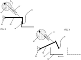
FIG. 2 is a schematic illustration of a portion of the lock core after a controller receives a valid authentication signal according to an embodiment of the invention; -
FIG. 3 is a schematic illustration of a portion of the lock core after a force is applied to the operating member according to an embodiment of the invention; -
FIG. 4 is a perspective view of the lock core when the operating member is in an extended position according to an embodiment of the invention; -
FIG. 5 is perspective view of the lock core when the operating member is in an extended position according to an embodiment of the invention; and -
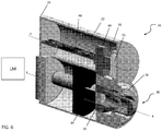
FIG. 6 is a cross-sectional view of another lock core not falling under the scope of the invention as defined by the appended claims. - An
electromechanical lock core 20 of a lock assembly is illustrated inFIG. 1 . Thelock core 20 includes anouter housing 22 within which various components of thelock core 20 are housed. Anoperating member 30 is arranged adjacent afirst end 24 of thehousing 22, and is movable generally linearly between a retracted position and an extended position. When theoperating member 30 is in the retracted position, as shown inFIG. 1 , theoperating member 30 is recessed within thehousing 22 such that afirst surface 32 of theoperating member 30 is adjacent to or substantially aligned with thefirst end 24 of thehousing 22. In one embodiment, thefirst surface 32 of theoperating member 30 has a generally non-round shape that prevents rotation of theoperating member 30 about an axis X when recessed within thehousing 22. Theoperating member 30 may be formed from a durable material resistant to drilling and vandalism. Thehousing 22, or a portion thereof, such as thefirst end 24 for example, may similarly be formed from a strengthen material capable of withstanding vandalism. - The
operating member 30 is operably coupled to a mechanical lock member (illustrated schematically by block LM) arranged adjacent thesecond end 26 of thehousing 22. Theoperating member 30 may include ashaft 34 that extends at least partially into the interior of thehousing 22. In the illustrated embodiment, theshaft 34 extends through the entire interior of thehousing 22 to the adjacent lock member LM. In one embodiment, at least oneengagement area 36, such as a protrusion or a recess for example, is arranged on a portion of theoperating member 30. For example, as shown inFIG. 1 , theshaft 34 includes a first engagement area 36' and asecond engagement area 36" separated by a distance. The shape of the at least oneengagement area 36 may be selected to prevent translation or rotation of theshaft 34 about an axis X as a result of interference with adjacent components housed within thehousing 22. - The
housing 22 additionally houses acontroller 40 operably coupled to anactuator 42. Areplaceable battery 41 may be configured to provide power to thecontroller 40 and theactuator 42. Thecontroller 40 is configured to receive an authentication signal from an external authentication device, such as a smartphone or an electronic key for example. The authentication device may be physically or wirelessly coupled to thecontroller 40. In one embodiment, an antenna (not shown) is coupled to thecontroller 40 and is arranged about the exterior of thehousing 22, such as adjacent thefirst end 24 for example. Theactuator 42 may be directly or indirectly coupled to acontrol member 46. Thecontrol member 46 is configured to retain theoperating member 30 in the retracted position, recessed within the interior of thehousing 22, until thecontroller 40 receives a valid authentication signal. In the illustrated embodiment, thecontrol member 46 is a generally L-shaped lever pivotable about afirst end 48 and connected to theactuator 42 with abiasing mechanism 52. An obstruction or protrusion (not shown) may extend from a portion of thehousing 22 adjacent thecontrol member 46 to limit movement of thecontrol member 46 when thecontroller 40 has not received a valid authentication signal, such as when thelock core 20 is vibrated or vandalized for example. When theoperating member 30 is recessed within thehousing 22, asecond end 50 of thecontrol member 46 is arranged in contact with the at least oneengagement area 36 to prevent theoperating member 30 from translating about the axis X to the extended position. - To operate the
lock core 20 illustrated inFIG. 1 , a person places an authentication device, such as a key or a cell phone for example, near the antenna, and thus thefirst end 24 of thelock core 20. The antenna transmits the authentication signal from the authentication device to thecontroller 40. In response to a valid authentication signal, thecontroller 40 will operate theactuator 42. In one embodiment, this movement of theactuator 42 will pivot thecontrol member 46 out of engagement with theoperating member 30; however, in the illustrated embodiment, rotation of theactuator 42 creates a stored energy in the biasing mechanism 52 (FIG. 2 ). Application of a force to thefront surface 32 of theoperating member 30 causes theengagement area 36 to translate along axis X out of contact with thecontrol member 46. As a result, the stored energy of thebiasing mechanism 52 is released, causing thecontrol member 46 to rotate away from the operating member 30 (FIG. 3 ). Once thecontrol member 46 is moved away from theoperating member 30, theoperating member 30 is biased to the extended position (FIG. 4 ), such as by a biasing mechanism (not shown) positioned aboutshaft 34 for example. - To extend the life of the
battery 41, the power required by thelock core 20 is minimized or eliminated when theoperating member 30 is biased to the extended position; however, once theoperating member 30 is returned to the retracted position, normal operation will resume. In the extended position, theoperating member 30 may be rotated, as shown inFIG. 5 , to operate the lock member LM coupled thereto, for example to open a door. The oblong shape of theoperating member 30 assists an operator in rotating theoperating member 30 to unlock the lock member LM. In one embodiment, once theoperating member 30 reaches its end of travel, theoperating member 30 is automatically returned to the retracted position within thehousing 22 and the lock member LM coupled thereto is relocked. In another embodiment, a user must actively move theoperating member 30 to the retracted position for thecontrol member 46 to re-engage theoperating member 30 and the lock member LM to lock. - A
lock core 20 that does not fall under the scope of the invention as defined by the appended claims is shown inFIG. 6 . In the illustrated embodiment, the operatingmember 30 includes a button configured to translate along an axis X between a retracted position and an extended position. Thecontrol member 46, arranged generally adjacent the operatingmember 30, is pivotable about an axis of rotation Y and includes acontact portion 56, such as a flange for example, extending partially about the periphery of thecontrol member 46. Thecontact portion 56 of thecontrol member 46 is configured to selectively engage theengagement area 36 of the operatingmember 30. When thecontact portion 56 of thecontrol member 46 and theengagement area 36 of the operatingmember 30 are in contact, the operatingmember 30 cannot translate generally linearly along axis X between the retracted position and the extended position. Thecontroller 40 is similarly coupled to thecontrol member 46 via an actuator 42 (not shown inFIG. 6 ). - Upon receipt of a valid authentication signal, the
actuator 42 coupled to thecontroller 40 rotates thecontrol member 46 about axis Y, to a first position, out of engagement with theengagement area 36 of the operatingmember 30. A sensor (not shown), operably coupled to thecontroller 40, may be used to detect if the operatingmember 30 is in the retracted position. If the sensor detects that the operating member is not in the retracted position, the controller may not operate the actuator upon receipt of a valid authentication signal. In one embodiment, abiasing mechanism 54 is configured to bias the operatingmember 30 to the extended position after thecontrol member 46 is rotated out of contact with theengagement area 36 of the operatingmember 30. Once extended, translational or rotational movement of the operatingmember 30 may operate the lock member LM coupled thereto. In one embodiment, translation of the operatingmember 30 back to the recessed position, such as by application of a force to thefront surface 32, operates the lock member LM, for example to release a door. In addition, translation of the operatingmember 30 back to the recessed position may also cause thecontrol member 46 to automatically reengage a portion of the operatingmember 30. - In another embodiment, the
lock core 20 may additionally include a core removal mechanism (not shown). Upon receipt of a unique identification signal, theactuator 42 rotates thecontrol member 46 about axis Y to a second position, distinct from the first position. In this second position, the operatingmember 30 couples to the core removal mechanism. The core removal mechanism may be configured for use in replacing thebattery 41 or for other purposes known to a person having ordinary skill in the art. - By retaining the operating
member 30 in a retracted position, recessed within thelock core 20 until a valid authentication signal is provided, thelock core 20 is resilient to unauthorized access. Thelock core 20 may be arranged within the thickness of a door, such that thefront surface 32 of the operatingmember 30 is substantially flush with the plane of the door. Because the operatingmember 30 generally does not take up any extra space outside of thelock core 20, thelock core 20 will also be less susceptible to vandalism. - While the invention has been described in detail in connection with only a limited number of embodiments, it should be readily understood that the invention is not limited to such disclosed embodiments. Rather, the invention can be modified to incorporate any number of variations, alterations, substitutions or equivalent arrangements not heretofore described, but which are commensurate with the invention, as defined by the appended claims. Additionally, while various embodiments of the invention have been described, it is to be understood that aspects of the invention may include only some of the described embodiments. Accordingly, the invention is not to be seen as limited by the foregoing description, but is only limited by the scope of the appended claims.
Claims (14)
- A lock core (20) for a lock assembly, comprising:a housing (22) having a first end (24);an operating member (30) configured to move between a retracted position and an extended position, wherein when the operating member is in the retracted position, the operating member is at least partially recessed within the housing;a control member (46) arranged within the housing and configured to selectively limit movement of the operating member between the retracted position and the extended position; and characterised by comprisinga first biasing mechanism configured to bias the operating member from the retracted position to the extended position; anda second biasing mechanism (52) extending between the actuator (42) and the control member, such that activation of the actuator creates a stored energy in the second biasing mechanism;wherein engagement between the control member and a portion of the operating member retains the control member first position after the stored energy is created in the second biasing mechanism;wherein the stored energy in the second biasing mechanism biases the control member out of engagement with the operating member when a force is applied to the operating member.
- The lock core according to claim 1, wherein the operating member (30) is generally non-round in shape.
- The lock core according to claim 1, wherein when the operating member (30) is in the retracted position, a front surface of the operating member is generally flush with the first end of the housing.
- The lock core according to claim 1, wherein the control member (46) is configured to engage a portion of the operating member to limit movement thereof.
- The lock core according to claim 4, wherein the controller (40) is operably coupled to the actuator (42) and is configured to activate the actuator to move the control member (46) to a first position out of engagement with the operating member upon receipt of a valid authentication signal.
- The lock core according to claim 4, wherein the operating member (30) includes at least one engagement area (36), and the control member (46) is configured to engage the at least one engagement area of the operating member to limit movement of the operating member from the retracted position.
- The lock core according to claim 6, wherein the control member (46) includes a contact portion (56) extending partially about its periphery.
- The lock core according to claim 4, further comprising:
a core removal mechanism, wherein the controller is operably coupled to the actuator (42) and is configured to activate the actuator to move the control member (46) to a second position out of engagement with the operating member such that the operating member couples to the core removal mechanism upon receipt of a unique identification signal. - The lock core according to claim 1, wherein a lock member is operably coupled to the operating member (30) and application of a force to the operating member, when in the extended position, operates the lock member.
- The lock core according to claim 9, wherein the operating member (30) is configured to bias to the retracted position once the lock member is operated.
- The lock core according to claim 9, wherein movement of the operating member (30) from the extended position to the retracted position causes the control member (46) to engage a portion of the operating member.
- A method of unlocking a lock assembly comprising a lock core according any of the claims 1-11, comprising:receiving a valid authentication signal;moving an actuator (42) coupled to a control member (46) configured to limit movement of an adjacent operating member (30); and characterised by comprising:disengaging the control member to allow movement of the operating member between the retracted position and an extended position, wherein application of a force to the operating member causes the control member and the operating member to disengage; andbiasing the operating member to the extended position.
- The method according to claim 12, further comprising applying a force to the operating member (30) to operate a lock member coupled thereto.
- The method according to claim 12, wherein a controller (40) receives a valid authentication signal from an external authentication device.
Applications Claiming Priority (2)
| Application Number | Priority Date | Filing Date | Title |
|---|---|---|---|
| US201361772855P | 2013-03-05 | 2013-03-05 | |
| PCT/US2014/018276 WO2014137665A1 (en) | 2013-03-05 | 2014-02-25 | Lock core with recessed pop out knob |
Publications (2)
| Publication Number | Publication Date |
|---|---|
| EP2964857A1 EP2964857A1 (en) | 2016-01-13 |
| EP2964857B1 true EP2964857B1 (en) | 2019-04-03 |
Family
ID=50343823
Family Applications (1)
| Application Number | Title | Priority Date | Filing Date |
|---|---|---|---|
| EP14711863.2A Active EP2964857B1 (en) | 2013-03-05 | 2014-02-25 | Lock core with recessed pop out knob |
Country Status (5)
| Country | Link |
|---|---|
| US (1) | US9708832B2 (en) |
| EP (1) | EP2964857B1 (en) |
| CN (1) | CN105378197B (en) |
| ES (1) | ES2725625T3 (en) |
| WO (1) | WO2014137665A1 (en) |
Families Citing this family (5)
| Publication number | Priority date | Publication date | Assignee | Title |
|---|---|---|---|---|
| EP2964857B1 (en) * | 2013-03-05 | 2019-04-03 | UTC Fire & Security Corporation | Lock core with recessed pop out knob |
| US10199826B2 (en) | 2014-09-30 | 2019-02-05 | Mosaic Power, LLC | System and method for combining load response and energy storage for grid regulation |
| US11952801B2 (en) | 2019-04-05 | 2024-04-09 | dormakaba USA, Inc | Electro-mechanical lock core with a cam member tailpiece |
| WO2020205863A1 (en) * | 2019-04-05 | 2020-10-08 | Dormakaba Usa Inc. | Electro-mechanical lock core with a cam member tailpiece |
| GB2618148A (en) * | 2022-04-29 | 2023-11-01 | Anti Ligature Shop Ltd | Anti-ligature keyless access control device |
Family Cites Families (10)
| Publication number | Priority date | Publication date | Assignee | Title |
|---|---|---|---|---|
| US5715713A (en) * | 1996-01-11 | 1998-02-10 | General Motors Corporation | Door latch locking actuator assembly |
| US6612141B2 (en) * | 2000-01-19 | 2003-09-02 | Schlage Lock Company | Interconnected lock with remote locking mechanism |
| WO2003064794A1 (en) | 2002-01-29 | 2003-08-07 | Investigación Y Transferencia De Tecnología, S.L. | Safety lock |
| US7296447B2 (en) * | 2005-02-24 | 2007-11-20 | The Stanley Works | Vending machine lock assembly |
| JP2007023686A (en) * | 2005-07-20 | 2007-02-01 | Toyota Motor Corp | Unlocking control device |
| US20110083482A1 (en) * | 2008-03-05 | 2011-04-14 | Knock N'lock Ltd. | Cam lock |
| US8544302B2 (en) * | 2010-01-25 | 2013-10-01 | Knock N'lock Ltd. | Door cylinder lock |
| AU2011213786B2 (en) * | 2010-09-09 | 2014-09-25 | Assa Abloy Australia Pty Limited | A Cavity Door End Pull Lock Set and Latch Set |
| CA2783072C (en) * | 2011-07-15 | 2020-02-18 | Medeco Security Locks, Inc. | Electronically-controlled removable core lock |
| EP2964857B1 (en) * | 2013-03-05 | 2019-04-03 | UTC Fire & Security Corporation | Lock core with recessed pop out knob |
-
2014
- 2014-02-25 EP EP14711863.2A patent/EP2964857B1/en active Active
- 2014-02-25 US US14/772,454 patent/US9708832B2/en active Active
- 2014-02-25 CN CN201480012795.6A patent/CN105378197B/en active Active
- 2014-02-25 ES ES14711863T patent/ES2725625T3/en active Active
- 2014-02-25 WO PCT/US2014/018276 patent/WO2014137665A1/en not_active Ceased
Non-Patent Citations (1)
| Title |
|---|
| None * |
Also Published As
| Publication number | Publication date |
|---|---|
| WO2014137665A1 (en) | 2014-09-12 |
| US9708832B2 (en) | 2017-07-18 |
| CN105378197A (en) | 2016-03-02 |
| US20160017639A1 (en) | 2016-01-21 |
| CN105378197B (en) | 2018-09-07 |
| EP2964857A1 (en) | 2016-01-13 |
| ES2725625T3 (en) | 2019-09-25 |
Similar Documents
| Publication | Publication Date | Title |
|---|---|---|
| US12624574B2 (en) | Locking assembly with spring mechanism | |
| US20190003206A1 (en) | Locking device with anti-jam mechanism | |
| US9708832B2 (en) | Lock core with recessed pop out knob | |
| US3999411A (en) | Lock knob control mechanism | |
| CN111226017A (en) | Mortise lock assembly with electric lock actuator | |
| US10724271B2 (en) | Independent RX spring cartridge for a mortise lock | |
| CN114096732A (en) | Door opener and door opening system for a motor vehicle | |
| US10017964B2 (en) | Latch mechanism for an exit device | |
| US10352067B2 (en) | Key monitoring door lock, door lock key monitoring system, and method thereof | |
| US20140331723A1 (en) | Electronic Locking Device | |
| US20210180364A1 (en) | Mortise lock and mortise lock systems and methods | |
| JP4170578B2 (en) | Plane handle | |
| EP2423414B1 (en) | Lock system and building locking system | |
| JP4723618B2 (en) | Locking device | |
| CN110939317B (en) | Control handle with entry monitoring system | |
| JP4711357B2 (en) | Lock handle device for door | |
| CN101189402A (en) | electronic lock system | |
| KR101990693B1 (en) | Locking device for screens preventing crimees and insections | |
| JP2015190197A (en) | Locking device for disaster prevention warehouse | |
| AU2014262187B2 (en) | Lock assembly with electrically controlled lock mechanism | |
| GB2552677A (en) | Lock assembly | |
| WO2025027999A1 (en) | Key storage device | |
| TR2024001120A1 (en) | A bipolar lock that can be locked both electromechanically and manually. | |
| NZ701861B (en) | Lock assembly with electrically controlled lock mechanism | |
| JP2010168874A (en) | Key storage system |
Legal Events
| Date | Code | Title | Description |
|---|---|---|---|
| PUAI | Public reference made under article 153(3) epc to a published international application that has entered the european phase |
Free format text: ORIGINAL CODE: 0009012 |
|
| 17P | Request for examination filed |
Effective date: 20150924 |
|
| AK | Designated contracting states |
Kind code of ref document: A1 Designated state(s): AL AT BE BG CH CY CZ DE DK EE ES FI FR GB GR HR HU IE IS IT LI LT LU LV MC MK MT NL NO PL PT RO RS SE SI SK SM TR |
|
| AX | Request for extension of the european patent |
Extension state: BA ME |
|
| DAX | Request for extension of the european patent (deleted) | ||
| GRAP | Despatch of communication of intention to grant a patent |
Free format text: ORIGINAL CODE: EPIDOSNIGR1 |
|
| STAA | Information on the status of an ep patent application or granted ep patent |
Free format text: STATUS: GRANT OF PATENT IS INTENDED |
|
| INTG | Intention to grant announced |
Effective date: 20180913 |
|
| GRAS | Grant fee paid |
Free format text: ORIGINAL CODE: EPIDOSNIGR3 |
|
| GRAA | (expected) grant |
Free format text: ORIGINAL CODE: 0009210 |
|
| STAA | Information on the status of an ep patent application or granted ep patent |
Free format text: STATUS: THE PATENT HAS BEEN GRANTED |
|
| AK | Designated contracting states |
Kind code of ref document: B1 Designated state(s): AL AT BE BG CH CY CZ DE DK EE ES FI FR GB GR HR HU IE IS IT LI LT LU LV MC MK MT NL NO PL PT RO RS SE SI SK SM TR |
|
| REG | Reference to a national code |
Ref country code: GB Ref legal event code: FG4D |
|
| REG | Reference to a national code |
Ref country code: CH Ref legal event code: EP Ref country code: CH Ref legal event code: NV Representative=s name: VALIPAT S.A. C/O BOVARD SA NEUCHATEL, CH Ref country code: AT Ref legal event code: REF Ref document number: 1115927 Country of ref document: AT Kind code of ref document: T Effective date: 20190415 |
|
| REG | Reference to a national code |
Ref country code: DE Ref legal event code: R096 Ref document number: 602014043975 Country of ref document: DE |
|
| REG | Reference to a national code |
Ref country code: IE Ref legal event code: FG4D |
|
| REG | Reference to a national code |
Ref country code: NL Ref legal event code: MP Effective date: 20190403 |
|
| REG | Reference to a national code |
Ref country code: LT Ref legal event code: MG4D |
|
| REG | Reference to a national code |
Ref country code: AT Ref legal event code: MK05 Ref document number: 1115927 Country of ref document: AT Kind code of ref document: T Effective date: 20190403 |
|
| REG | Reference to a national code |
Ref country code: ES Ref legal event code: FG2A Ref document number: 2725625 Country of ref document: ES Kind code of ref document: T3 Effective date: 20190925 |
|
| PG25 | Lapsed in a contracting state [announced via postgrant information from national office to epo] |
Ref country code: NL Free format text: LAPSE BECAUSE OF FAILURE TO SUBMIT A TRANSLATION OF THE DESCRIPTION OR TO PAY THE FEE WITHIN THE PRESCRIBED TIME-LIMIT Effective date: 20190403 |
|
| PG25 | Lapsed in a contracting state [announced via postgrant information from national office to epo] |
Ref country code: AL Free format text: LAPSE BECAUSE OF FAILURE TO SUBMIT A TRANSLATION OF THE DESCRIPTION OR TO PAY THE FEE WITHIN THE PRESCRIBED TIME-LIMIT Effective date: 20190403 Ref country code: SE Free format text: LAPSE BECAUSE OF FAILURE TO SUBMIT A TRANSLATION OF THE DESCRIPTION OR TO PAY THE FEE WITHIN THE PRESCRIBED TIME-LIMIT Effective date: 20190403 Ref country code: PT Free format text: LAPSE BECAUSE OF FAILURE TO SUBMIT A TRANSLATION OF THE DESCRIPTION OR TO PAY THE FEE WITHIN THE PRESCRIBED TIME-LIMIT Effective date: 20190803 Ref country code: NO Free format text: LAPSE BECAUSE OF FAILURE TO SUBMIT A TRANSLATION OF THE DESCRIPTION OR TO PAY THE FEE WITHIN THE PRESCRIBED TIME-LIMIT Effective date: 20190703 Ref country code: FI Free format text: LAPSE BECAUSE OF FAILURE TO SUBMIT A TRANSLATION OF THE DESCRIPTION OR TO PAY THE FEE WITHIN THE PRESCRIBED TIME-LIMIT Effective date: 20190403 Ref country code: LT Free format text: LAPSE BECAUSE OF FAILURE TO SUBMIT A TRANSLATION OF THE DESCRIPTION OR TO PAY THE FEE WITHIN THE PRESCRIBED TIME-LIMIT Effective date: 20190403 Ref country code: HR Free format text: LAPSE BECAUSE OF FAILURE TO SUBMIT A TRANSLATION OF THE DESCRIPTION OR TO PAY THE FEE WITHIN THE PRESCRIBED TIME-LIMIT Effective date: 20190403 Ref country code: CZ Free format text: LAPSE BECAUSE OF FAILURE TO SUBMIT A TRANSLATION OF THE DESCRIPTION OR TO PAY THE FEE WITHIN THE PRESCRIBED TIME-LIMIT Effective date: 20190403 |
|
| PG25 | Lapsed in a contracting state [announced via postgrant information from national office to epo] |
Ref country code: RS Free format text: LAPSE BECAUSE OF FAILURE TO SUBMIT A TRANSLATION OF THE DESCRIPTION OR TO PAY THE FEE WITHIN THE PRESCRIBED TIME-LIMIT Effective date: 20190403 Ref country code: LV Free format text: LAPSE BECAUSE OF FAILURE TO SUBMIT A TRANSLATION OF THE DESCRIPTION OR TO PAY THE FEE WITHIN THE PRESCRIBED TIME-LIMIT Effective date: 20190403 Ref country code: BG Free format text: LAPSE BECAUSE OF FAILURE TO SUBMIT A TRANSLATION OF THE DESCRIPTION OR TO PAY THE FEE WITHIN THE PRESCRIBED TIME-LIMIT Effective date: 20190703 Ref country code: GR Free format text: LAPSE BECAUSE OF FAILURE TO SUBMIT A TRANSLATION OF THE DESCRIPTION OR TO PAY THE FEE WITHIN THE PRESCRIBED TIME-LIMIT Effective date: 20190704 Ref country code: PL Free format text: LAPSE BECAUSE OF FAILURE TO SUBMIT A TRANSLATION OF THE DESCRIPTION OR TO PAY THE FEE WITHIN THE PRESCRIBED TIME-LIMIT Effective date: 20190403 |
|
| PG25 | Lapsed in a contracting state [announced via postgrant information from national office to epo] |
Ref country code: IS Free format text: LAPSE BECAUSE OF FAILURE TO SUBMIT A TRANSLATION OF THE DESCRIPTION OR TO PAY THE FEE WITHIN THE PRESCRIBED TIME-LIMIT Effective date: 20190803 Ref country code: AT Free format text: LAPSE BECAUSE OF FAILURE TO SUBMIT A TRANSLATION OF THE DESCRIPTION OR TO PAY THE FEE WITHIN THE PRESCRIBED TIME-LIMIT Effective date: 20190403 |
|
| REG | Reference to a national code |
Ref country code: DE Ref legal event code: R097 Ref document number: 602014043975 Country of ref document: DE |
|
| PG25 | Lapsed in a contracting state [announced via postgrant information from national office to epo] |
Ref country code: EE Free format text: LAPSE BECAUSE OF FAILURE TO SUBMIT A TRANSLATION OF THE DESCRIPTION OR TO PAY THE FEE WITHIN THE PRESCRIBED TIME-LIMIT Effective date: 20190403 Ref country code: DK Free format text: LAPSE BECAUSE OF FAILURE TO SUBMIT A TRANSLATION OF THE DESCRIPTION OR TO PAY THE FEE WITHIN THE PRESCRIBED TIME-LIMIT Effective date: 20190403 Ref country code: RO Free format text: LAPSE BECAUSE OF FAILURE TO SUBMIT A TRANSLATION OF THE DESCRIPTION OR TO PAY THE FEE WITHIN THE PRESCRIBED TIME-LIMIT Effective date: 20190403 Ref country code: SK Free format text: LAPSE BECAUSE OF FAILURE TO SUBMIT A TRANSLATION OF THE DESCRIPTION OR TO PAY THE FEE WITHIN THE PRESCRIBED TIME-LIMIT Effective date: 20190403 |
|
| PLBE | No opposition filed within time limit |
Free format text: ORIGINAL CODE: 0009261 |
|
| STAA | Information on the status of an ep patent application or granted ep patent |
Free format text: STATUS: NO OPPOSITION FILED WITHIN TIME LIMIT |
|
| PG25 | Lapsed in a contracting state [announced via postgrant information from national office to epo] |
Ref country code: SM Free format text: LAPSE BECAUSE OF FAILURE TO SUBMIT A TRANSLATION OF THE DESCRIPTION OR TO PAY THE FEE WITHIN THE PRESCRIBED TIME-LIMIT Effective date: 20190403 Ref country code: IT Free format text: LAPSE BECAUSE OF FAILURE TO SUBMIT A TRANSLATION OF THE DESCRIPTION OR TO PAY THE FEE WITHIN THE PRESCRIBED TIME-LIMIT Effective date: 20190403 |
|
| 26N | No opposition filed |
Effective date: 20200106 |
|
| PG25 | Lapsed in a contracting state [announced via postgrant information from national office to epo] |
Ref country code: TR Free format text: LAPSE BECAUSE OF FAILURE TO SUBMIT A TRANSLATION OF THE DESCRIPTION OR TO PAY THE FEE WITHIN THE PRESCRIBED TIME-LIMIT Effective date: 20190403 |
|
| PG25 | Lapsed in a contracting state [announced via postgrant information from national office to epo] |
Ref country code: SI Free format text: LAPSE BECAUSE OF FAILURE TO SUBMIT A TRANSLATION OF THE DESCRIPTION OR TO PAY THE FEE WITHIN THE PRESCRIBED TIME-LIMIT Effective date: 20190403 |
|
| REG | Reference to a national code |
Ref country code: BE Ref legal event code: MM Effective date: 20200229 |
|
| PG25 | Lapsed in a contracting state [announced via postgrant information from national office to epo] |
Ref country code: MC Free format text: LAPSE BECAUSE OF FAILURE TO SUBMIT A TRANSLATION OF THE DESCRIPTION OR TO PAY THE FEE WITHIN THE PRESCRIBED TIME-LIMIT Effective date: 20190403 Ref country code: LU Free format text: LAPSE BECAUSE OF NON-PAYMENT OF DUE FEES Effective date: 20200225 |
|
| PG25 | Lapsed in a contracting state [announced via postgrant information from national office to epo] |
Ref country code: IE Free format text: LAPSE BECAUSE OF NON-PAYMENT OF DUE FEES Effective date: 20200225 |
|
| PG25 | Lapsed in a contracting state [announced via postgrant information from national office to epo] |
Ref country code: BE Free format text: LAPSE BECAUSE OF NON-PAYMENT OF DUE FEES Effective date: 20200229 |
|
| PGFP | Annual fee paid to national office [announced via postgrant information from national office to epo] |
Ref country code: CH Payment date: 20220120 Year of fee payment: 9 |
|
| PG25 | Lapsed in a contracting state [announced via postgrant information from national office to epo] |
Ref country code: MT Free format text: LAPSE BECAUSE OF FAILURE TO SUBMIT A TRANSLATION OF THE DESCRIPTION OR TO PAY THE FEE WITHIN THE PRESCRIBED TIME-LIMIT Effective date: 20190403 Ref country code: CY Free format text: LAPSE BECAUSE OF FAILURE TO SUBMIT A TRANSLATION OF THE DESCRIPTION OR TO PAY THE FEE WITHIN THE PRESCRIBED TIME-LIMIT Effective date: 20190403 |
|
| PG25 | Lapsed in a contracting state [announced via postgrant information from national office to epo] |
Ref country code: MK Free format text: LAPSE BECAUSE OF FAILURE TO SUBMIT A TRANSLATION OF THE DESCRIPTION OR TO PAY THE FEE WITHIN THE PRESCRIBED TIME-LIMIT Effective date: 20190403 |
|
| P01 | Opt-out of the competence of the unified patent court (upc) registered |
Effective date: 20230602 |
|
| REG | Reference to a national code |
Ref country code: CH Ref legal event code: PL |
|
| PG25 | Lapsed in a contracting state [announced via postgrant information from national office to epo] |
Ref country code: LI Free format text: LAPSE BECAUSE OF NON-PAYMENT OF DUE FEES Effective date: 20230228 Ref country code: CH Free format text: LAPSE BECAUSE OF NON-PAYMENT OF DUE FEES Effective date: 20230228 |
|
| REG | Reference to a national code |
Ref country code: GB Ref legal event code: 732E Free format text: REGISTERED BETWEEN 20240905 AND 20240911 |
|
| REG | Reference to a national code |
Ref country code: DE Ref legal event code: R081 Ref document number: 602014043975 Country of ref document: DE Owner name: HONEYWELL INTERNATIONAL INC. (N.D.GES.D.STAATE, US Free format text: FORMER OWNER: UTC FIRE & SECURITY CORP., FARMINGTON, CONN., US Ref country code: DE Ref legal event code: R081 Ref document number: 602014043975 Country of ref document: DE Owner name: CARRIER FIRE & SECURITY LLC (N.D.GES.D.STAATES, US Free format text: FORMER OWNER: UTC FIRE & SECURITY CORP., FARMINGTON, CONN., US Ref country code: DE Ref legal event code: R081 Ref document number: 602014043975 Country of ref document: DE Owner name: CARRIER FIRE & SECURITY CORP. (N.D.GES.D.STAAT, US Free format text: FORMER OWNER: UTC FIRE & SECURITY CORP., FARMINGTON, CONN., US |
|
| REG | Reference to a national code |
Ref country code: ES Ref legal event code: PC2A Owner name: CARRIER FIRE & SECURITY , LLC Effective date: 20241121 |
|
| REG | Reference to a national code |
Ref country code: DE Ref legal event code: R081 Ref document number: 602014043975 Country of ref document: DE Owner name: HONEYWELL INTERNATIONAL INC. (N.D.GES.D.STAATE, US Free format text: FORMER OWNER: CARRIER FIRE & SECURITY CORP. (N.D.GES.D.STAATES DELAWARE), FARMINGTON, CT, US Ref country code: DE Ref legal event code: R081 Ref document number: 602014043975 Country of ref document: DE Owner name: CARRIER FIRE & SECURITY LLC (N.D.GES.D.STAATES, US Free format text: FORMER OWNER: CARRIER FIRE & SECURITY CORP. (N.D.GES.D.STAATES DELAWARE), FARMINGTON, CT, US |
|
| REG | Reference to a national code |
Ref country code: DE Ref legal event code: R081 Ref document number: 602014043975 Country of ref document: DE Owner name: HONEYWELL INTERNATIONAL INC. (N.D.GES.D.STAATE, US Free format text: FORMER OWNER: CARRIER FIRE & SECURITY LLC (N.D.GES.D.STAATES DELAWARE), FARMINGTON, CT, US |
|
| PGFP | Annual fee paid to national office [announced via postgrant information from national office to epo] |
Ref country code: GB Payment date: 20260223 Year of fee payment: 13 |
|
| PGFP | Annual fee paid to national office [announced via postgrant information from national office to epo] |
Ref country code: ES Payment date: 20260317 Year of fee payment: 13 |
|
| PGFP | Annual fee paid to national office [announced via postgrant information from national office to epo] |
Ref country code: DE Payment date: 20260220 Year of fee payment: 13 |
|
| PGFP | Annual fee paid to national office [announced via postgrant information from national office to epo] |
Ref country code: FR Payment date: 20260224 Year of fee payment: 13 |