EP2963834A1 - Tuning circuit and receiver - Google Patents
Tuning circuit and receiver Download PDFInfo
- Publication number
- EP2963834A1 EP2963834A1 EP15174473.7A EP15174473A EP2963834A1 EP 2963834 A1 EP2963834 A1 EP 2963834A1 EP 15174473 A EP15174473 A EP 15174473A EP 2963834 A1 EP2963834 A1 EP 2963834A1
- Authority
- EP
- European Patent Office
- Prior art keywords
- frequency
- band
- adjustment portion
- pass filter
- tuning circuit
- Prior art date
- Legal status (The legal status is an assumption and is not a legal conclusion. Google has not performed a legal analysis and makes no representation as to the accuracy of the status listed.)
- Granted
Links
Images




Classifications
-
- H—ELECTRICITY
- H04—ELECTRIC COMMUNICATION TECHNIQUE
- H04N—PICTORIAL COMMUNICATION, e.g. TELEVISION
- H04N5/00—Details of television systems
- H04N5/44—Receiver circuitry for the reception of television signals according to analogue transmission standards
- H04N5/50—Tuning indicators; Automatic tuning control
-
- H—ELECTRICITY
- H04—ELECTRIC COMMUNICATION TECHNIQUE
- H04B—TRANSMISSION
- H04B1/00—Details of transmission systems, not covered by a single one of groups H04B3/00 - H04B13/00; Details of transmission systems not characterised by the medium used for transmission
- H04B1/06—Receivers
- H04B1/10—Means associated with receiver for limiting or suppressing noise or interference
- H04B1/1027—Means associated with receiver for limiting or suppressing noise or interference assessing signal quality or detecting noise/interference for the received signal
-
- H—ELECTRICITY
- H04—ELECTRIC COMMUNICATION TECHNIQUE
- H04B—TRANSMISSION
- H04B1/00—Details of transmission systems, not covered by a single one of groups H04B3/00 - H04B13/00; Details of transmission systems not characterised by the medium used for transmission
- H04B1/06—Receivers
- H04B1/16—Circuits
- H04B1/1638—Special circuits to enhance selectivity of receivers not otherwise provided for
-
- H—ELECTRICITY
- H04—ELECTRIC COMMUNICATION TECHNIQUE
- H04B—TRANSMISSION
- H04B1/00—Details of transmission systems, not covered by a single one of groups H04B3/00 - H04B13/00; Details of transmission systems not characterised by the medium used for transmission
- H04B1/06—Receivers
- H04B1/16—Circuits
- H04B1/26—Circuits for superheterodyne receivers
- H04B1/28—Circuits for superheterodyne receivers the receiver comprising at least one semiconductor device having three or more electrodes
-
- H—ELECTRICITY
- H04—ELECTRIC COMMUNICATION TECHNIQUE
- H04N—PICTORIAL COMMUNICATION, e.g. TELEVISION
- H04N21/00—Selective content distribution, e.g. interactive television or video on demand [VOD]
- H04N21/40—Client devices specifically adapted for the reception of or interaction with content, e.g. set-top-box [STB]; Operations thereof
- H04N21/41—Structure of client; Structure of client peripherals
- H04N21/426—Internal components of the client ; Characteristics thereof
- H04N21/42607—Internal components of the client ; Characteristics thereof for processing the incoming bitstream
-
- H—ELECTRICITY
- H04—ELECTRIC COMMUNICATION TECHNIQUE
- H04N—PICTORIAL COMMUNICATION, e.g. TELEVISION
- H04N21/00—Selective content distribution, e.g. interactive television or video on demand [VOD]
- H04N21/40—Client devices specifically adapted for the reception of or interaction with content, e.g. set-top-box [STB]; Operations thereof
- H04N21/47—End-user applications
-
- H—ELECTRICITY
- H04—ELECTRIC COMMUNICATION TECHNIQUE
- H04B—TRANSMISSION
- H04B1/00—Details of transmission systems, not covered by a single one of groups H04B3/00 - H04B13/00; Details of transmission systems not characterised by the medium used for transmission
- H04B1/06—Receivers
- H04B1/10—Means associated with receiver for limiting or suppressing noise or interference
- H04B1/1027—Means associated with receiver for limiting or suppressing noise or interference assessing signal quality or detecting noise/interference for the received signal
- H04B2001/1072—Means associated with receiver for limiting or suppressing noise or interference assessing signal quality or detecting noise/interference for the received signal by tuning the receiver frequency
-
- H—ELECTRICITY
- H04—ELECTRIC COMMUNICATION TECHNIQUE
- H04N—PICTORIAL COMMUNICATION, e.g. TELEVISION
- H04N21/00—Selective content distribution, e.g. interactive television or video on demand [VOD]
- H04N21/40—Client devices specifically adapted for the reception of or interaction with content, e.g. set-top-box [STB]; Operations thereof
- H04N21/43—Processing of content or additional data, e.g. demultiplexing additional data from a digital video stream; Elementary client operations, e.g. monitoring of home network or synchronising decoder's clock; Client middleware
- H04N21/438—Interfacing the downstream path of the transmission network originating from a server, e.g. retrieving encoded video stream packets from an IP network
- H04N21/4383—Accessing a communication channel
Definitions
- the present invention relates to a tuning circuit that extracts a signal corresponding to a predetermined channel form a television radio wave.
- a tuning circuit is used for extracting a band part corresponding to the selected channel from the television radio wave received by an antenna.
- the tuning circuit can extract a broadcast program by passing only a part synchronizing with the band of the selected channel.
- the tuning circuit using a superheterodyne method is disclosed as the tuning circuit.
- the tuning circuit using the superheterodyne method extracts a desired output signal by mixing the television radio wave with a local signal corresponding to the selected channel.
- noise can occur in the output signal due to an area where the broadcast program is watched, an environment where the antenna is installed in a house, and influence of radiation from peripheral devices. If the noise occurs in the output signal, noise images are generated on a screen output by an output device (e.g., display panel). This adversely affects viewing of the broadcast program.
- an output device e.g., display panel
- the present invention provides a receiver that can improve a quality of the output signal.
- One aspect of the present invention provides a tuning circuit that outputs an output signal corresponding to a selected channel from a broadcast signal, comprising: a first band-pass filter that passes a first predetermined frequency band corresponding to the selected channel in the broadcast signal; a mixing circuit that generates a mixed signal by mixing a signal having a predetermined frequency band corresponding to the selected channel with the broadcast signal passed through the first band-pass filter; and a second band-pass filter that passes a second predetermined frequency band in the mixed signal, wherein at least one of a first frequency of the first band-pass filter and a second frequency of the second band-pass filter of the selected channel is changed.
- At least one of a first adjustment portion that specifies the first frequency of the first band-pass filter and a second adjustment portion that specifies the second frequency of the second band-pass filter is provided.
- the first adjustment portion and the second adjustment portion adjust the first frequency and the second frequency to make an evaluation value of an output signal output from the second band-pass filter become a predetermined value.
- the first and the second band-pass filters can be any band-pass filter as long as it can change a predetermined frequency pass band with a center frequency as a reference.
- the evaluation value is a value by which the output signal can be evaluated.
- a C/N ratio Carrier to noise ratio
- a BER Bit Error Rate
- the C/N ratio means a power ratio between a carrier C and a noise N in the output signal.
- the BER is a value showing an error rate of the output signal.
- the predetermined value can be a value exceeding a preliminarily determined optimal value (threshold value), a best value in a plurality of measurement, and an average value of a plurality of measurement.
- the first adjustment portion and the second adjustment portion can acquire the evaluation value of the externally detected output signal or calculate the evaluation value from the output signal received by the first adjustment portion.
- the signal passed through the second band-pass filter is output from a predetermined output circuit.
- the output circuit is a general term of a circuit for amplifying, demodulating and error-correcting the signal passed through the second band-pass filter.
- the first adjustment portion adjusts the first frequency (frequency pass band) of the first variable band-pass filter to make the evaluation value of the output signal of the first variable band-pass filter become a predetermined value.
- the second adjustment portion adjusts the second frequency (frequency pass band) of the second variable band-pass filter to make the evaluation value of the output signal of the second variable band-pass filter become a predetermined value. Therefore, the noise component can be efficiently removed from the input signal. Thus, the quality (e.g., image quality) of the program to be viewed can be improved.
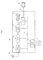
- Fig. 1 is a block diagram showing a receiver 100 as an example.
- the receiver 100 shown in Fig. 1 is a recording device having a tuning circuit 40.
- the tuning circuit 40 is connected to an antenna 200.
- the tuning circuit 40 extracts a signal (TS packet) corresponding to the selected channel from the television radio wave received by the antenna 200.
- the tuning circuit 40 outputs the output signal corresponding to the selected channel from the broadcast signal.
- the TS packet is comprised of image and sound of the selected channel and program information. Note that the specific configuration of the tuning circuit 40 will be explained later.
- An encoder 50 is connected to an output side of the tuning circuit 40.
- the encoder 50 encodes the signal output from the tuning circuit 40.
- a stream controller 51 is connected to an output side of the encoder 50.
- the stream controller 51 records the TS packet encoded by the encoder 50 in a storage area of an auxiliary storage device 52.
- the auxiliary storage device 52 can be magnetic storage devices such as an HDD, semiconductor storage devices such as an SSD (solid state drive) and optical discs such as a DVD and a BD.
- a decoder 53 is connected to the stream controller 51. When reproducing the TS packet recorded in the auxiliary storage device 52, the stream controller 51 outputs the TS packet to the decoder 53.
- the decoder 53 decodes the read TS packet and outputs it via an output terminal 56.
- a display device 60 which functions as an output device, can be connected to the output terminal 56. The display device 60 outputs the signal received via the output terminal 56 as image and sound.
- Each components of the receiver 100 is connected to a system controller 55 via a bus 54.
- the system controller 55 includes not illustrated CPU, ROM and RAM.
- the system controller 55 expands programs recorded in the ROM to the RAM and executes them.
- the system controller can control driving of the receiver 100 such as tuning executed by the tuning circuit 40 and recording of the TS packet.
- the system controller 55 can receive operation commands from a remote controller 70. When a user operates the remote controller 70, the system controller 55 controls the tuning circuit 40 via the bus 54 to select the channel.
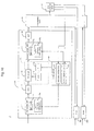
- Fig. 2 is a block diagram showing the tuning circuit 40 as an example.
- the tuning circuit 40 performs the tuning processing using the superheterodyne method. Namely, the tuning circuit 40 synthesizes an RF signal with a local signal and extracts a mixed signal (TS packet) corresponding to the selected channel.
- the tuning circuit 40 shown in Fig. 2 includes a tuner 10, a demodulation circuit 30 and an error correction circuit 31.
- the tuner 10 extracts the signal of the channel (band) selected by the tuning in the television radio wave received by the antenna 200.
- the demodulation circuit 30 demodulates the signal extracted by the tuner 10.
- the error correction circuit 31 corrects errors of the signal demodulated by the demodulation circuit 30.
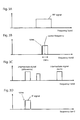
- Figs. 3A to 3D are diagrams explaining a change of the signal generated in the tuning circuit 40.
- Fig. 3A shows an input signal (RF signal) at a point A of Fig. 2 .
- Fig. 3B shows the signal at a point B of Fig. 2 .
- Fig. 3C shows the signal at a point C of Fig. 2 .
- Fig. 3D shows the signal at a point D of Fig. 2 .
- a first variable band-pass filter 11 is connected to an input terminal.
- the first variable band-pass filter 11 will be also referred to as a first variable BPF 11.
- a frequency pass band of the first variable band-pass filter 11 is, for example, set to 6 MHz with a center frequency as a reference.
- the RF signal ( Fig. 3A ) passing through the first variable BPF 11 only the frequency component that belongs to the frequency pass band of 6 MHz with the center frequency as the center is passed, and the frequency component of other bands is attenuated ( Fig. 3B ). Note that, in Fig. 3B , a noise is included in the lowest frequency of the frequency pass band.
- the first variable BPF 11 includes a BPF block 11a and a center frequency setting block 11b.
- the BPF block 11a passes only the frequency pass band located above and below a predetermined center frequency.
- the center frequency setting block 11b specifies the center frequency. By shifting the center frequency above and below (also expressed as back and forth) according to the frequency of the selected channel selected in the tuning, a predetermined frequency pass band can be changed. As explained above, the first band-pass filter11 passes the frequency band corresponding to the selected channel from the broadcast signal.
- a mixing circuit 13 is connected to an output side of the first variable BPF 11 via an LNA 12.
- the LNA 12 applies low noise amplification to the RF signal passed through the first variable BPF 11.
- the mixing circuit 13 mixes the local signal corresponding to the selected channel with the RF signal passed through the first variable BPF 11 to generate a mixed signal.
- the mixing circuit 13 shown in Fig. 2 includes a VCO 15, a PLL 16 and a MIX circuit 14.
- the VCO 15 generates the local signal corresponding to the selected channel.
- the PLL 16 specifies the frequency band of the VCO 15.
- the MIX circuit 14 synthesizes the local signal with the RF signal output from the LNA 12. According to the control signal sent from a later mentioned control portion 20, the PLL 16 specifies the frequency band corresponding to the selected channel.
- the mixing circuit 13 From the RF signal mixed with the local signal by the mixing circuit 13, the mixed signals having the frequency of sum and difference of the RF signal and the local signal are generated.
- a second variable band-pass filter 17 is connected to an output side of the mixing circuit 13.
- the second variable band-pass filter 17 passes only the low frequency component and attenuates other bands.
- the second variable BPF 17 includes a BPF block 17a and a center frequency setting block 17b.
- the BPF block 17a passes only the frequency pass band located above and below a predetermined center frequency.
- the center frequency setting block 17b specifies the center frequency.
- the center frequency and the frequency pass band of the second variable BPF 17 are set individually for each selected channel. Therefore, as shown in Fig. 3D , only the low frequency component in the mixed signal passes through the second variable BPF 17 and the high frequency component is attenuated.
- a width of the pass band of the second variable band-pass filter 17 is set to 6 MHz, for example. Note that, in Fig. 3D , a noise is included in the lowest frequency of the frequency pass band. As explained above, the second band-pass filter17 passes a predetermined frequency band of the mixed signal.
- An AMP (amplifier) 18 is connected to an output side of the second variable BPF 17.
- the AMP 18 amplifies the mixed signal passed through the second variable BPF 17.
- the demodulation circuit 30 is connected to an output side of the AMP 18.
- the demodulation circuit 30 demodulates the mixed signal output from the AMP 18 and generates an IF signal (output signal).
- the error correction circuit 31 is connected to the demodulation circuit 30.
- the error correction circuit 31 corrects errors of the IF signal demodulated by the demodulation circuit 30.
- the error correction circuit 31 calculates a C/N ratio and a BER as an evaluation value evaluating a reception state.
- the error correction circuit 31 is connected to the control portion 20.
- the error correction circuit 31 outputs the evaluation value to the control portion 20. In this embodiment, the error correction circuit 31 outputs the evaluation value.
- the demodulation circuit 30 can be used for outputting the evaluation value, other evaluation value calculating circuits can be used instead.
- the control portion 20 applies the frequency band of the VCO signal corresponding to the selected channel to the mixing circuit 13.
- the control portion 20 performs a feedback control of the first variable band-pass filter 11 and the second variable band-pass filter 17 based on the evaluation value output from the error correction circuit 31.
- the control portion 20 adjusts the frequency pass bands of the first variable band-pass filter 11 and the second variable band-pass filter 17 according to the output of the error correction circuit 31.
- the control portion 20 shown in Fig. 2 includes a first adjustment portion 21 and a second adjustment portion 22.
- the first adjustment portion 21 adjusts the first frequency and the frequency pass band of the first variable BPF 11 to make the C/N ratio obtained as the evaluation value become an optimum value.
- the second adjustment portion 22 adjusts the second frequency and the frequency pass band of the second variable BPF 17 to make the BER obtained as the evaluation value become an optimum value.
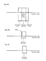
- Figs. 4A to 4C are diagrams explaining a process of improving quality of the IF signal by using the first adjustment portion 21 and the second adjustment portion 22.
- Fig. 4A is a diagram showing a relation between a frequency pass band and an attenuation band of the first BPF 11 as an example.
- the frequency band in a predetermined range above and below the center frequency is the frequency pass band.
- the frequency band above or below the frequency pass band is an attenuation band. In the attenuation band, the frequency component is gradually attenuated. Above or below the attenuation band, the frequency component is almost completely blocked.
- Fig. 4B is a diagram showing the signal (signal passed through the first variable BPF 11) on which the noise is superposed.
- Fig. 4C is a diagram showing the signal (signal passed through the first variable BPF 11) on which the noise is not superposed.
- the frequency pass band is passed and the signal is attenuated in the attenuation band.
- noise is superposed on the signal of the frequency pass band of the first BPF 11. If the noise is superposed on the signal, quality of the IF signal, which is generated later, is deteriorated. Therefore, the first adjustment portion 21 adjusts the center frequency and the frequency pass band of the first BPF 11 back and forth, and the band on which the noise is superposed is set to be the attenuation band of the first BPF 11.
- the noise can be reduced and the quality of the IF signal can be improved.
- the noise is attenuated in the attenuation band by shifting the frequency pass band of the first BPF 11 to the high frequency side.
- the noise when the noise is generated at a slightly lower frequency side of the frequency pass band, the noise can be included in the attenuation band by slightly shifting the center frequency to the high frequency side.
- the signal on which the noise is not superposed can be obtained.
- the evaluation value is improved as explained later.
- the center frequency can be specified so that the evaluation value becomes the optimum value or the evaluation value exceeds a predetermined threshold value. In other words, whether the evaluation value is improved or not should be judged by comparing the evaluation value with an index value.
- the quality of the IF signal can be improved by adjusting the frequency pass band and attenuating the noise.
- the first adjustment portion 21 and the second adjustment portion 22 adjust the first frequency and the second frequency to make the evaluation value of the output signal output from the first and second band-pass filters 11, 17 become a predetermined value.
- control portion 20 performs a process of improving quality each time when the user operates the remote controller 70 to select the channel.
- the process of improving quality the noise component of the IF signal is reduced and the quality of the output of the display device 60 can be improved.
- Fig. 5 is a flow chart explaining the process of improving quality performed by the tuning circuit 40.
- step S1 of Fig. 5 the control portion 20 turns on the function of improving quality of the RF signal, and the procedure advances to step S2.
- step S2 the control portion 20 (first adjustment portion 21) specifies the frequency pass band (initial value) corresponding to the selected channel and acquires an initial value A of the C/N ratio of the IF signal.
- the C/N ratio can be acquired from the error correction circuit 31, for example.
- the control portion 20 stores the center frequency and the frequency pass band for each channel to be selected.
- the control portion 20 applies the frequency pass band corresponding to the selected channel to the mixing circuit 13. Note that the control portion 20 only needs to record at least either of the center frequency and the frequency pass band for each channel to be selected.
- step S3 the control portion 20 changes the frequency pass band of the first variable BPF 11.
- the control portion 20 minutely changes the center frequency of the frequency pass band to change the frequency pass band of the first variable BPF 11. Specifically, when the control portion 20 changes the center frequency of the first variable BPF 11, the frequency pass band is changed.
- the process that the control portion 20 changes the frequency pass band of the first variable BPF 11 is also referred to as "the control portion 20 adjusts the frequency pass band of the first variable BPF 11.”
- step S4 the control portion 20 acquires a C/N ratio C of the IF signal, which is acquired by the frequency pass band after the adjustment.
- step S5 the control portion 20 compares the initial value A with the C/N ratio C and judges whether or not the C/N ratio is improved. If the initial value A is lower than the acquired C/N ratio C, the C/N ratio is improved. Therefore, the control portion 20 finishes the adjustment of the first BPF 11, and the procedure advances to step S8. On the other hand, if the initial value A is higher than the C/N ratio C, the C/N ratio is not improved. Therefore, the procedure advances to step S6.
- step S6 the control portion 20 refers to a count frequency a, which is the number of times of adjusting the frequency pass band.
- T1 a threshold value
- the procedure advances to step S7.
- step S7 the control portion 20 adds 1 to the count frequency a, and the procedure returns to step S3.
- step S4 the control portion 20 adjusts the frequency pass band of the first variable BPF 11.
- step S4 the control portion 20 acquires the C/N ratio C after the adjustment. Then, the control portion 20 compares the initial value A with the C/N ratio C of the IF signal after the frequency pass band is adjusted. If the C/N ratio is not improved (A ⁇ C), the procedure returns to steps S6.
- step S6 if the count frequency a is equal to or more than the threshold value (step S6: a ⁇ T1), the procedure advances to step S8.
- the center frequency is further changed when the evaluation value is improved.
- the setting of the center frequency is finished when the evaluation value is not improved so as not to further deteriorate the evaluation value.
- a target center frequency can be stored and the target center frequency can be revised by applying the current first frequency as a candidate for the target center frequency only when the evaluation value is improved. Then, steps S3 to S7 are repeated. In this way, when the loop of the above procedures is finished, the evaluation value is improved the most when the target center frequency is applied.
- the first adjustment portion 21 acquires the evaluation value corresponding to the changed first frequency after the first frequency is changed, and the first adjustment portion 21 applies the changed first frequency to the first band-pass filter 11 when the evaluation value is improved.
- the evaluation value is a carrier/noise ratio.
- the first adjustment portion 21 uses the carrier/noise ratio as the evaluation value.
- step S8 the control portion 20 specifies the center frequency and the frequency pass band of the second variable BPF 17 corresponding to the selected channel, and acquires an initial value B of a BER value.
- step S9 the control portion 20 adjusts the frequency pass band of the second variable BPF 17.
- step S9 the control portion 20 increases and decreases the center frequency of the frequency pass band of the second variable BPF 17 to adjust the frequency pass band. Note that the control portion 20 only needs to record at least either of the center frequency and the frequency pass band for each channel to be selected.
- step S10 the control portion 20 acquires a BER value D of the IF signal, which is acquired by the frequency pass band after the adjustment.
- step S11 the control portion 20 compares the initial value B with the BER value D and judges whether or not the BER value is improved. If the BER value D is improved (B>D), the procedure advances to steps S 14. On the other hand, if the BER value D is not improved (B ⁇ D), the procedure advances to steps S12.
- step S12 the control portion 20 refers to a count frequency b, which is the number of times of adjusting the frequency pass band.
- T2 a threshold value
- the control portion 20 adds 1 to the count frequency b.
- step S10 the control portion 20 acquires the BER value D of the IF signal after the frequency pass band is changed. If the BER value is improved (step S12: B>D) or the count frequency b is equal to or more than the threshold value T2 (step S13: b ⁇ T2), the procedure advances to step S14.
- the center frequency is further changed when the evaluation value is improved.
- the setting of the center frequency is finished when the evaluation value is not improved so as not to further deteriorate the evaluation value.
- the center frequency of the second variable BPF 17 can be stored each time when the evaluation value is improved.
- the finally stored center frequency can be the target center frequency.
- the target center frequency can be stored and the target center frequency can be revised by applying the current first frequency as a candidate for the target center frequency only when the evaluation value is improved. Then, steps S10 to S13 are repeated. In this way, when the loop of the above procedures is finished, the evaluation value is improved the most when the target center frequency is applied.
- the second adjustment portion 22 acquires the evaluation value corresponding to the changed second frequency after the first frequency is changed, and the second adjustment portion 22 applies the changed second frequency to the second band-pass filter17 when the evaluation value is improved.
- the evaluation value is a bit error rate.
- the second adjustment portion 22 uses the bit error rate as the evaluation value.
- step S14 the control portion 20 displays the result of improvement of the C/N ratio and the BER value on a screen.
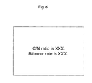
- Fig. 6 shows an OSD screen displayed on the display device 60 as an example. In the OSD screen shown in Fig. 6 , both the C/N ratio and the BER value after improving the quality are displayed on the screen.
- step S14 corresponds to a display portion that displays the evaluation values acquired after the first frequency and the second frequency are adjusted.
- the second adjustment portion 22 adjusts the second frequency pass band of the second variable band-pass filter 17 to make the BER of the IF signal become an optimum value. Therefore, the noise component can be efficiently removed from the IF signal and the quality (e.g., image quality) of the program to be viewed can be improved.
- the first adjustment portion 21 uses the carrier/noise ratio as the evaluation value
- the second adjustment portion 22 uses the bit error rate as the evaluation value. Since the quality of the IF signal can be evaluated by using the different evaluation values, the quality can be further improved. Thus, the evaluation value used in the first adjustment portion 21 is different from the evaluation value used in the second adjustment portion 22. Namely, a kind of the evaluation value used is different between the first adjustment portion and the second adjustment portion.
- first adjustment portion 21 and the second adjustment portion 22 adjust the frequency pass bands of the first BPF 11 and the second BPF 17 each time when the channel is selected, adequate quality of the output signal is maintained when the channel is selected. In other words, the first adjustment portion 21 and the second adjustment portion 22 adjust the first frequency and the second frequency when the channel is selected.
- Fig. 7 is a flow chart explaining a process of improving quality executed by the tuning circuit 40 in the second embodiment. Also in the second embodiment, the frequency pass bands of the first BPF 11 and the second BPF 17 are adjusted based on the C/N ratio and the BER value of the IF signal.
- step S21 of Fig. 7 the control portion 20 turns on the function of improving quality of the RF signal, and the procedure advances to step S22.
- step S22 the control portion 20 specifies the frequency pass band corresponding to the selected channel and acquires a C/N ratio Ci of the IF signal.
- "i" is a value of identifying the acquired C/N ratio.
- the control portion 20 stores the center frequency and the frequency pass band for each channel to be selected.
- step S23 the control portion 20 adjusts the frequency pass band of the first variable BPF 11.
- step S24 the control portion 20 acquires the C/N ratio Ci of the IF signal.
- step S25 the control portion 20 refers to the count frequency a, which is the number of times of adjusting the frequency pass band.
- the control portion 20 finishes the adjustment of the frequency pass band of the first variable BPF 11 when the count frequency a is equal to or more than the threshold value T1.
- the procedure advances to step S26.
- step S26 the control portion 20 adds 1 to the count frequency a, and the procedure returns to step S23.
- step S23 the control portion 20 adjusts the frequency pass band of the first variable BPF 11.
- step S24 the control portion 20 acquires the C/N ratio Ci after the adjustment.
- step S25 if the count frequency a is equal to or more than the threshold value T1 (step S25: a ⁇ T1), the procedure advances to step S27.
- step S27 the control portion 20 determines the most optimal C/N ratio Ci from the acquired C/N ratios Ci and applies the frequency pass band corresponding to the most optimal C/N ratio Ci to the first BPF 11. For example, if the C/N ratios C0 to CT1 are stored and the C/N ratio Ci is the most optimal value, the center frequency when the C/N ratio Ci is acquired is applied to the center frequency of the first BPF 11. This center frequency can be calculated as the frequency that is adjusted i times from the initial value.
- the center frequency corresponding to the most optimal evaluation value is calculated. Therefore, the first frequency is changed and the evaluation values corresponding to each of the changed first frequency are acquired. Then, the most optimal evaluation value is selected from the acquired evaluation values and the center frequency corresponding to the most optimal evaluation value is applied to the first frequency of the first band-pass filter.
- the evaluation value to be selected is not limited to the most optimal value. For example, the evaluation value exceeding a predetermined value or the evaluation value equal to a predetermined value can be selected instead.
- step S28 the control portion 20 acquires the BER value Dj of the IF signal.
- "j" is a value of identifying the acquired BER value.
- the control portion 20 stores the center frequency and the frequency pass band for each channel to be selected.
- step S29 the control portion 20 adjusts the frequency pass band of the second variable BPF 17.
- step S29 the control portion 20 increases and decreases the center frequency of the frequency pass band of the second variable BPF 17 to adjust the frequency pass band.
- step S30 the control portion 20 acquires the BER value Dj of the IF signal, which is acquired by the frequency pass band after the adjustment.
- step S31 the control portion 20 refers to the count frequency b, which is the number of times of adjusting the frequency pass band.
- the procedure advances to step S32.
- step S32 the control portion 20 adds 1 to the count frequency b.
- control portion 20 After returned to step S29, the control portion 20 adjusts the frequency pass band of the second variable BPF 17. In step S30, the control portion 20 acquires the BER value Dj of the IF signal after the frequency pass band is adjusted.
- step S21 If the count frequency b is equal to or more than the threshold value T2 (step S21: b ⁇ T2), the procedure advances to step S33.
- step S33 the control portion 20 determines the most optimal BER value from the acquired BER values Dj and applies the frequency pass band corresponding to the most optimal BER value to the second BPF 17.
- the center frequency corresponding to the most optimal evaluation value is calculated. Therefore, the second frequency is changed and the evaluation values corresponding to each of the changed second frequency are acquired. Then, the most optimal evaluation value is selected from the acquired evaluation values and the center frequency corresponding to the most optimal evaluation value is applied to the second frequency of the second band-pass filter.
- the evaluation value to be selected is not limited to the most optimal value. For example, the evaluation value exceeding a predetermined value or the evaluation value equal to a predetermined value can be selected instead.
- step S34 the control portion 20 displays the result of improvement of the C/N ratio and the BER value on a screen. Therefore, both the C/N ratio and the BER value after improving the quality are displayed on the display device 60.
- all of the C/N ratios and the BER values are stored when the center frequency is gradually changed. Therefore, the value that appears as a peak suddenly can be ignored by judging that the value is influenced by the noise.
- a representative value not influenced by the noise can be used by calculating an average value of three continuous values. The method of calculating the representative value is not limited to the above method. Various methods can be used instead.
- the first adjustment portion 21 and the second adjustment portion 22 change the first frequency and the second frequency, and then acquire the evaluation values corresponding to the changed first frequency and second frequency. Then, the first adjustment portion 21 and the second adjustment portion 22 select a representative evaluation value from the acquired evaluation values based on a plurality of evaluation values, and apply the center frequency corresponding to the representative evaluation value to the first frequency of the first band-pass filter 11 or the second frequency of the second band-pass filter 17.
- the frequency pass band explained in the first embodiment and the second embodiment is stored for each channel, and the frequency pass band corresponding to the selected channel is applied when the channel is selected.
- Fig. 8 is a block diagram showing the tuning circuit of the third embodiment.
- the tuning circuit 40 shown in Fig. 8 includes a memory (storage portion) 19 in addition to the first BPF 11, the LNA 12, the mixing circuit 13, the second BPF 17, AMP 18, the control portion 20 and the demodulation circuit 30.
- the control portion 20 functionally includes a setting portion 23 in addition to the first adjustment portion 21 and the second adjustment portion 22.
- the memory 19 stores the center frequency and the frequency pass band (first frequency pass band) of the first BPF 11 and the center frequency and the frequency pass band (second frequency pass band) of the second BPF 17 in association with the channel.
- Fig. 9 is a diagram explaining the frequency pass band stored in a memory 19.
- the first frequency pass band and the second frequency pass band are stored for each of the selected channel preliminarily set in the control portion 20.
- the first frequency pass band is a value that the first adjustment portion 21 applies to the first BPF 11 by using the process explained in the first embodiment or the second embodiment.
- the second frequency pass band is a value that the second adjustment portion 22 applies to the second BPF 17 by using the process explained in the first embodiment or the second embodiment.
- the memory 19 can be any device as long as it is a volatile memory capable of rewriting data. For example, a PROM and a flash memory can be used.
- the setting portion 23 applies the first frequency pass band stored in the memory 19 to the first variable BPF 11 and applies the second frequency pass band stored in the memory 19 to the second variable BPF 17 each time when the channel is selected.
- the adjustment of the first frequency pass band and the second frequency pass band is not performed each time when the channel is selected.
- the adjustment is performed only when it is required. Since the process of the adjustment is not performed each time when the channel is selected, a load of the control portion 20 can be reduced.
- the stored center frequency can be normally used and an optimal center frequency can be searched in a predetermined timing, e.g., after a predetermined period has passed. This can prevent an influence caused by change due to passage of time.
- the receiver 100 can include a plurality of tuning circuits. Each of the tuning circuits can have the function of improving quality shown in the first embodiment and the second embodiment.
- Fig. 10 is a diagram showing a part of the receiver 100 of the fourth embodiment.
- three tuners 10#1 to 10#3 are provided.
- Each of the tuners 10#1 to 10#3 is connected to the demodulation circuit 30.
- the tuners 10#1 to 10#3 can extract the IF signal corresponding to the selected channel from the RF signal received from the antenna 200.
- the tuners 10#1 to 10#3 include the first variable BPF, the mixing circuit, the second variable BPF, the AMP and the control portion.
- the demodulation circuit 30 is connected to the error correction circuit 31.
- the error correction circuit 31 is connected to the control portion 20.
- the error correction circuit 31 outputs the C/N ratio and the BER value of the IF signal to the control portion 20.
- the demodulation circuit 30 is commonly used for the tuners 10#1 to 10#3. However, the demodulation circuit 30 can be separately provided each for the tuners 10#1 to 10#3. From the above, in the fourth embodiment, the receiver 100 includes a plurality of tuning circuits 40.
- the receiver 100 when the receiver 100 includes a plurality of tuning circuits, the quality of the output signal can be improved for each of the selected channel.
- the receiver 100 includes at least two tuning circuits.
- the recording device used in the explanation is merely an example of the receiver.
- the receiver can be any devises as long as it has a tuning function.
- a set-top box, a television receiver and a personal computer can be used as the receiver.
- the tuner 10 can have a band-pass filter for acquiring the frequency band of UHF 470 to 578 MHz, which is the frequency band in which digital television broadcast is broadcasted, before the first variable BPF.
Landscapes
- Engineering & Computer Science (AREA)
- Signal Processing (AREA)
- Computer Networks & Wireless Communication (AREA)
- Multimedia (AREA)
- Circuits Of Receivers In General (AREA)
- Two-Way Televisions, Distribution Of Moving Picture Or The Like (AREA)
- Noise Elimination (AREA)
Abstract
Description
- This patent specification is based on Japanese patent application, No.
2014-136239 filed on July 1, 2014 - The present invention relates to a tuning circuit that extracts a signal corresponding to a predetermined channel form a television radio wave.
- A tuning circuit is used for extracting a band part corresponding to the selected channel from the television radio wave received by an antenna. The tuning circuit can extract a broadcast program by passing only a part synchronizing with the band of the selected channel.
- In
Patent documents - In the Patent documents, filters are provided before and after a mixing circuit and pass bands of the filters are fixed. Therefore, an input signal input from the antenna passes through the filter and then is mixed with the local signal by a mixer. Then, an output from the mixer is input to the filter, amplified by an amplifier, and output to a demodulation circuit as shown in
Patent documents - [Patent Document 1] Japanese Patent Application Laid-Open No.
2009-058485 - [Patent Document 2] Japanese Patent Application Laid-Open No.
2009-016912 - In some cases, noise can occur in the output signal due to an area where the broadcast program is watched, an environment where the antenna is installed in a house, and influence of radiation from peripheral devices. If the noise occurs in the output signal, noise images are generated on a screen output by an output device (e.g., display panel). This adversely affects viewing of the broadcast program.
- The present invention provides a receiver that can improve a quality of the output signal.
- One aspect of the present invention provides a tuning circuit that outputs an output signal corresponding to a selected channel from a broadcast signal, comprising: a first band-pass filter that passes a first predetermined frequency band corresponding to the selected channel in the broadcast signal; a mixing circuit that generates a mixed signal by mixing a signal having a predetermined frequency band corresponding to the selected channel with the broadcast signal passed through the first band-pass filter; and a second band-pass filter that passes a second predetermined frequency band in the mixed signal, wherein at least one of a first frequency of the first band-pass filter and a second frequency of the second band-pass filter of the selected channel is changed.
- In another aspect of the present invention, at least one of a first adjustment portion that specifies the first frequency of the first band-pass filter and a second adjustment portion that specifies the second frequency of the second band-pass filter is provided.
- In another aspect of the present invention, the first adjustment portion and the second adjustment portion adjust the first frequency and the second frequency to make an evaluation value of an output signal output from the second band-pass filter become a predetermined value.
- The first and the second band-pass filters can be any band-pass filter as long as it can change a predetermined frequency pass band with a center frequency as a reference.
- The evaluation value is a value by which the output signal can be evaluated. A C/N ratio (Carrier to noise ratio), a BER (Bit Error Rate), and a combination of them can be used as the evaluation value. The C/N ratio means a power ratio between a carrier C and a noise N in the output signal. The BER is a value showing an error rate of the output signal.
- The predetermined value can be a value exceeding a preliminarily determined optimal value (threshold value), a best value in a plurality of measurement, and an average value of a plurality of measurement.
- The first adjustment portion and the second adjustment portion can acquire the evaluation value of the externally detected output signal or calculate the evaluation value from the output signal received by the first adjustment portion.
- The signal passed through the second band-pass filter is output from a predetermined output circuit. The output circuit is a general term of a circuit for amplifying, demodulating and error-correcting the signal passed through the second band-pass filter.
- The first adjustment portion adjusts the first frequency (frequency pass band) of the first variable band-pass filter to make the evaluation value of the output signal of the first variable band-pass filter become a predetermined value. The second adjustment portion adjusts the second frequency (frequency pass band) of the second variable band-pass filter to make the evaluation value of the output signal of the second variable band-pass filter become a predetermined value. Therefore, the noise component can be efficiently removed from the input signal. Thus, the quality (e.g., image quality) of the program to be viewed can be improved.
-
-
Fig. 1 is a block diagram showing areceiver 100 as an example. -
Fig. 2 is a block diagram showing atuning circuit 40 as an example. -
Figs. 3A to 3D are diagrams explaining a change of a signal generated in thetuning circuit 40. -
Figs. 4A to 4C are diagrams explaining a process of improving quality of an IF signal by using afirst adjustment portion 21 and asecond adjustment portion 22. -
Fig. 5 is a flow chart explaining a change of the signal changed in the process inFig. 4 . -
Fig. 6 is a diagram showing an OSD screen displayed on adisplay device 60 as an example. -
Fig. 7 is a flow chart explaining a process of improving quality executed by thetuning circuit 40 in the second embodiment. -
Fig. 8 is a block diagram showing the tuning circuit of the third embodiment. -
Fig. 9 is a diagram explaining a frequency pass band stored in amemory 19. -
Fig. 10 is a diagram showing a part of areceiver 100 of the fourth embodiment. - Hereafter, embodiments of the present invention will be explained according to the following order.
- 1. First embodiment:
- (1) Configuration of receiver
- (2) Configuration of tuning circuit
- (3) Method of improving quality
- 2. Second embodiment:
- 3. Third embodiment:
- 4. Fourth embodiment:
- 5. Other embodiments:
-
Fig. 1 is a block diagram showing areceiver 100 as an example. Thereceiver 100 shown inFig. 1 is a recording device having a tuningcircuit 40. Thetuning circuit 40 is connected to anantenna 200. Thetuning circuit 40 extracts a signal (TS packet) corresponding to the selected channel from the television radio wave received by theantenna 200. In other words, thetuning circuit 40 outputs the output signal corresponding to the selected channel from the broadcast signal. The TS packet is comprised of image and sound of the selected channel and program information. Note that the specific configuration of thetuning circuit 40 will be explained later. - An
encoder 50 is connected to an output side of thetuning circuit 40. Theencoder 50 encodes the signal output from thetuning circuit 40. Astream controller 51 is connected to an output side of theencoder 50. Thestream controller 51 records the TS packet encoded by theencoder 50 in a storage area of anauxiliary storage device 52. Theauxiliary storage device 52 can be magnetic storage devices such as an HDD, semiconductor storage devices such as an SSD (solid state drive) and optical discs such as a DVD and a BD. Adecoder 53 is connected to thestream controller 51. When reproducing the TS packet recorded in theauxiliary storage device 52, thestream controller 51 outputs the TS packet to thedecoder 53. Thedecoder 53 decodes the read TS packet and outputs it via anoutput terminal 56. Adisplay device 60, which functions as an output device, can be connected to theoutput terminal 56. Thedisplay device 60 outputs the signal received via theoutput terminal 56 as image and sound. - Each components of the
receiver 100 is connected to asystem controller 55 via abus 54. Thesystem controller 55 includes not illustrated CPU, ROM and RAM. Thesystem controller 55 expands programs recorded in the ROM to the RAM and executes them. Thus, the system controller can control driving of thereceiver 100 such as tuning executed by thetuning circuit 40 and recording of the TS packet. In addition, thesystem controller 55 can receive operation commands from aremote controller 70. When a user operates theremote controller 70, thesystem controller 55 controls thetuning circuit 40 via thebus 54 to select the channel. - Next, the configuration of the
tuning circuit 40 will be explained in detail.Fig. 2 is a block diagram showing thetuning circuit 40 as an example. Thetuning circuit 40 performs the tuning processing using the superheterodyne method. Namely, thetuning circuit 40 synthesizes an RF signal with a local signal and extracts a mixed signal (TS packet) corresponding to the selected channel. Thetuning circuit 40 shown inFig. 2 includes atuner 10, ademodulation circuit 30 and anerror correction circuit 31. Thetuner 10 extracts the signal of the channel (band) selected by the tuning in the television radio wave received by theantenna 200. Thedemodulation circuit 30 demodulates the signal extracted by thetuner 10. Theerror correction circuit 31 corrects errors of the signal demodulated by thedemodulation circuit 30. -
Figs. 3A to 3D are diagrams explaining a change of the signal generated in thetuning circuit 40.Fig. 3A shows an input signal (RF signal) at a point A ofFig. 2 .Fig. 3B shows the signal at a point B ofFig. 2 .Fig. 3C shows the signal at a point C ofFig. 2 .Fig. 3D shows the signal at a point D ofFig. 2 . - The configuration of the
tuner 10 shown inFig. 2 will be explained. A first variable band-pass filter 11 is connected to an input terminal. Hereafter, the first variable band-pass filter 11 will be also referred to as a firstvariable BPF 11. A frequency pass band of the first variable band-pass filter 11 is, for example, set to 6 MHz with a center frequency as a reference. In the RF signal (Fig. 3A ) passing through the firstvariable BPF 11, only the frequency component that belongs to the frequency pass band of 6 MHz with the center frequency as the center is passed, and the frequency component of other bands is attenuated (Fig. 3B ). Note that, inFig. 3B , a noise is included in the lowest frequency of the frequency pass band. The firstvariable BPF 11 includes aBPF block 11a and a centerfrequency setting block 11b. TheBPF block 11a passes only the frequency pass band located above and below a predetermined center frequency. The centerfrequency setting block 11b specifies the center frequency. By shifting the center frequency above and below (also expressed as back and forth) according to the frequency of the selected channel selected in the tuning, a predetermined frequency pass band can be changed. As explained above, the first band-pass filter11 passes the frequency band corresponding to the selected channel from the broadcast signal. - A mixing
circuit 13 is connected to an output side of the firstvariable BPF 11 via anLNA 12. TheLNA 12 applies low noise amplification to the RF signal passed through the firstvariable BPF 11. - The mixing
circuit 13 mixes the local signal corresponding to the selected channel with the RF signal passed through the firstvariable BPF 11 to generate a mixed signal. The mixingcircuit 13 shown inFig. 2 includes aVCO 15, aPLL 16 and aMIX circuit 14. TheVCO 15 generates the local signal corresponding to the selected channel. ThePLL 16 specifies the frequency band of theVCO 15. TheMIX circuit 14 synthesizes the local signal with the RF signal output from theLNA 12. According to the control signal sent from a later mentionedcontrol portion 20, thePLL 16 specifies the frequency band corresponding to the selected channel. - As shown in
Fig. 3C , from the RF signal mixed with the local signal by the mixingcircuit 13, the mixed signals having the frequency of sum and difference of the RF signal and the local signal are generated. - A second variable band-
pass filter 17 is connected to an output side of the mixingcircuit 13. In the mixed signal containing a low frequency component (difference) and a high frequency component (sum), the second variable band-pass filter 17 passes only the low frequency component and attenuates other bands. The secondvariable BPF 17 includes aBPF block 17a and a centerfrequency setting block 17b. TheBPF block 17a passes only the frequency pass band located above and below a predetermined center frequency. The centerfrequency setting block 17b specifies the center frequency. The center frequency and the frequency pass band of the secondvariable BPF 17 are set individually for each selected channel. Therefore, as shown inFig. 3D , only the low frequency component in the mixed signal passes through the secondvariable BPF 17 and the high frequency component is attenuated. A width of the pass band of the second variable band-pass filter 17 is set to 6 MHz, for example. Note that, inFig. 3D , a noise is included in the lowest frequency of the frequency pass band. As explained above, the second band-pass filter17 passes a predetermined frequency band of the mixed signal. - An AMP (amplifier) 18 is connected to an output side of the second
variable BPF 17. TheAMP 18 amplifies the mixed signal passed through the secondvariable BPF 17. - The
demodulation circuit 30 is connected to an output side of theAMP 18. Thedemodulation circuit 30 demodulates the mixed signal output from theAMP 18 and generates an IF signal (output signal). Theerror correction circuit 31 is connected to thedemodulation circuit 30. Theerror correction circuit 31 corrects errors of the IF signal demodulated by thedemodulation circuit 30. In addition, theerror correction circuit 31 calculates a C/N ratio and a BER as an evaluation value evaluating a reception state. Theerror correction circuit 31 is connected to thecontrol portion 20. Theerror correction circuit 31 outputs the evaluation value to thecontrol portion 20. In this embodiment, theerror correction circuit 31 outputs the evaluation value. Although thedemodulation circuit 30 can be used for outputting the evaluation value, other evaluation value calculating circuits can be used instead. - The
control portion 20 applies the frequency band of the VCO signal corresponding to the selected channel to the mixingcircuit 13. In addition, thecontrol portion 20 performs a feedback control of the first variable band-pass filter 11 and the second variable band-pass filter 17 based on the evaluation value output from theerror correction circuit 31. Specifically, thecontrol portion 20 adjusts the frequency pass bands of the first variable band-pass filter 11 and the second variable band-pass filter 17 according to the output of theerror correction circuit 31. Thecontrol portion 20 shown inFig. 2 includes afirst adjustment portion 21 and asecond adjustment portion 22. Thefirst adjustment portion 21 adjusts the first frequency and the frequency pass band of the firstvariable BPF 11 to make the C/N ratio obtained as the evaluation value become an optimum value. Thesecond adjustment portion 22 adjusts the second frequency and the frequency pass band of the secondvariable BPF 17 to make the BER obtained as the evaluation value become an optimum value. -
Figs. 4A to 4C are diagrams explaining a process of improving quality of the IF signal by using thefirst adjustment portion 21 and thesecond adjustment portion 22.Fig. 4A is a diagram showing a relation between a frequency pass band and an attenuation band of thefirst BPF 11 as an example. The frequency band in a predetermined range above and below the center frequency is the frequency pass band. The frequency band above or below the frequency pass band is an attenuation band. In the attenuation band, the frequency component is gradually attenuated. Above or below the attenuation band, the frequency component is almost completely blocked.Fig. 4B is a diagram showing the signal (signal passed through the first variable BPF 11) on which the noise is superposed.Fig. 4C is a diagram showing the signal (signal passed through the first variable BPF 11) on which the noise is not superposed. - As shown in
Fig. 4A , in the RF signal passing through thefirst BPF 11, the frequency pass band is passed and the signal is attenuated in the attenuation band. InFig. 4B , noise is superposed on the signal of the frequency pass band of thefirst BPF 11. If the noise is superposed on the signal, quality of the IF signal, which is generated later, is deteriorated. Therefore, thefirst adjustment portion 21 adjusts the center frequency and the frequency pass band of thefirst BPF 11 back and forth, and the band on which the noise is superposed is set to be the attenuation band of thefirst BPF 11. Thus, the noise can be reduced and the quality of the IF signal can be improved. InFig. 4C , the noise is attenuated in the attenuation band by shifting the frequency pass band of thefirst BPF 11 to the high frequency side. Specifically, as shown inFig. 4B , when the noise is generated at a slightly lower frequency side of the frequency pass band, the noise can be included in the attenuation band by slightly shifting the center frequency to the high frequency side. As a result, as shown inFig. 4C , the signal on which the noise is not superposed can be obtained. In addition, since the noise is not superposed, the evaluation value is improved as explained later. In other words, if the center frequency is specified so that the evaluation value is improved, the noise can be prevented from being superposed. The center frequency can be specified so that the evaluation value becomes the optimum value or the evaluation value exceeds a predetermined threshold value. In other words, whether the evaluation value is improved or not should be judged by comparing the evaluation value with an index value. - Similarly, also in the
second BPF 17, the quality of the IF signal can be improved by adjusting the frequency pass band and attenuating the noise. - As explained above, the
first adjustment portion 21 and thesecond adjustment portion 22 adjust the first frequency and the second frequency to make the evaluation value of the output signal output from the first and second band-pass filters - Next, a method of improving quality using the
tuning circuit 40 will be explained. - In the first embodiment, the
control portion 20 performs a process of improving quality each time when the user operates theremote controller 70 to select the channel. By the process of improving quality, the noise component of the IF signal is reduced and the quality of the output of thedisplay device 60 can be improved. -
Fig. 5 is a flow chart explaining the process of improving quality performed by thetuning circuit 40. - In step S1 of
Fig. 5 , thecontrol portion 20 turns on the function of improving quality of the RF signal, and the procedure advances to step S2. - In step S2, the control portion 20 (first adjustment portion 21) specifies the frequency pass band (initial value) corresponding to the selected channel and acquires an initial value A of the C/N ratio of the IF signal. The C/N ratio can be acquired from the
error correction circuit 31, for example. For example, thecontrol portion 20 stores the center frequency and the frequency pass band for each channel to be selected. When the signal of the channel selected by the user is received via thesystem controller 55, thecontrol portion 20 applies the frequency pass band corresponding to the selected channel to the mixingcircuit 13. Note that thecontrol portion 20 only needs to record at least either of the center frequency and the frequency pass band for each channel to be selected. - In step S3, the
control portion 20 changes the frequency pass band of the firstvariable BPF 11. As shown inFig. 4A , thecontrol portion 20 minutely changes the center frequency of the frequency pass band to change the frequency pass band of the firstvariable BPF 11. Specifically, when thecontrol portion 20 changes the center frequency of the firstvariable BPF 11, the frequency pass band is changed. Hereafter, the process that thecontrol portion 20 changes the frequency pass band of the firstvariable BPF 11 is also referred to as "thecontrol portion 20 adjusts the frequency pass band of the firstvariable BPF 11." In step S4, thecontrol portion 20 acquires a C/N ratio C of the IF signal, which is acquired by the frequency pass band after the adjustment. - In step S5, the
control portion 20 compares the initial value A with the C/N ratio C and judges whether or not the C/N ratio is improved. If the initial value A is lower than the acquired C/N ratio C, the C/N ratio is improved. Therefore, thecontrol portion 20 finishes the adjustment of thefirst BPF 11, and the procedure advances to step S8. On the other hand, if the initial value A is higher than the C/N ratio C, the C/N ratio is not improved. Therefore, the procedure advances to step S6. - In step S6, the
control portion 20 refers to a count frequency a, which is the number of times of adjusting the frequency pass band. In the first embodiment, thecontrol portion 20 finishes the adjustment of the frequency pass band of the first variable band-pass filter 11 when the count frequency a is equal to or more than a threshold value T1 (e.g. T1=10). Here, since the count frequency a is less than the threshold value T1, the procedure advances to step S7. - In step S7, the
control portion 20 adds 1 to the count frequency a, and the procedure returns to step S3. - After returned to step S3, the
control portion 20 adjusts the frequency pass band of the firstvariable BPF 11. In step S4, thecontrol portion 20 acquires the C/N ratio C after the adjustment. Then, thecontrol portion 20 compares the initial value A with the C/N ratio C of the IF signal after the frequency pass band is adjusted. If the C/N ratio is not improved (A≥C), the procedure returns to steps S6. - In step S6, if the count frequency a is equal to or more than the threshold value (step S6: a≥T1), the procedure advances to step S8.
- In other words, the center frequency is further changed when the evaluation value is improved. On the other hand, the setting of the center frequency is finished when the evaluation value is not improved so as not to further deteriorate the evaluation value.
- As another method, a target center frequency can be stored and the target center frequency can be revised by applying the current first frequency as a candidate for the target center frequency only when the evaluation value is improved. Then, steps S3 to S7 are repeated. In this way, when the loop of the above procedures is finished, the evaluation value is improved the most when the target center frequency is applied.
- In the above described process, the
first adjustment portion 21 acquires the evaluation value corresponding to the changed first frequency after the first frequency is changed, and thefirst adjustment portion 21 applies the changed first frequency to the first band-pass filter 11 when the evaluation value is improved. - In the above described process, the evaluation value is a carrier/noise ratio. The
first adjustment portion 21 uses the carrier/noise ratio as the evaluation value. - In step S8, the
control portion 20 specifies the center frequency and the frequency pass band of the secondvariable BPF 17 corresponding to the selected channel, and acquires an initial value B of a BER value. - In step S9, the
control portion 20 adjusts the frequency pass band of the secondvariable BPF 17. In step S9, thecontrol portion 20 increases and decreases the center frequency of the frequency pass band of the secondvariable BPF 17 to adjust the frequency pass band. Note that thecontrol portion 20 only needs to record at least either of the center frequency and the frequency pass band for each channel to be selected. - In step S10, the
control portion 20 acquires a BER value D of the IF signal, which is acquired by the frequency pass band after the adjustment. - In step S11, the
control portion 20 compares the initial value B with the BER value D and judges whether or not the BER value is improved. If the BER value D is improved (B>D), the procedure advances tosteps S 14. On the other hand, if the BER value D is not improved (B≤D), the procedure advances to steps S12. - In step S12, the
control portion 20 refers to a count frequency b, which is the number of times of adjusting the frequency pass band. In the first embodiment, thecontrol portion 20 finishes the adjustment of the frequency pass band of the second variable band-pass filter 17 when the count frequency b is equal to or more than a threshold value T2 (e.g. T2=10). Here, since the count frequency b is less than the threshold value T2, the procedure advances to step S13. In step S13, thecontrol portion 20 adds 1 to the count frequency b. - After returned to step S9, the
control portion 20 changes the frequency pass band of the secondvariable BPF 17. In step S10, thecontrol portion 20 acquires the BER value D of the IF signal after the frequency pass band is changed. If the BER value is improved (step S12: B>D) or the count frequency b is equal to or more than the threshold value T2 (step S13: b≥T2), the procedure advances to step S14. - In other words, the center frequency is further changed when the evaluation value is improved. On the other hand, the setting of the center frequency is finished when the evaluation value is not improved so as not to further deteriorate the evaluation value.
- As another method, the center frequency of the second
variable BPF 17 can be stored each time when the evaluation value is improved. In this way, the finally stored center frequency can be the target center frequency. Specifically, the target center frequency can be stored and the target center frequency can be revised by applying the current first frequency as a candidate for the target center frequency only when the evaluation value is improved. Then, steps S10 to S13 are repeated. In this way, when the loop of the above procedures is finished, the evaluation value is improved the most when the target center frequency is applied. - In the above described process, the
second adjustment portion 22 acquires the evaluation value corresponding to the changed second frequency after the first frequency is changed, and thesecond adjustment portion 22 applies the changed second frequency to the second band-pass filter17 when the evaluation value is improved. - In the above described process, the evaluation value is a bit error rate. The
second adjustment portion 22 uses the bit error rate as the evaluation value. - In step S14, the
control portion 20 displays the result of improvement of the C/N ratio and the BER value on a screen.Fig. 6 shows an OSD screen displayed on thedisplay device 60 as an example. In the OSD screen shown inFig. 6 , both the C/N ratio and the BER value after improving the quality are displayed on the screen. - Therefore, the process of step S14 corresponds to a display portion that displays the evaluation values acquired after the first frequency and the second frequency are adjusted.
- As explained above, in the first embodiment, after the
first adjustment portion 21 adjusts the first frequency pass band of the first variable band-pass filter 11 to make the C/N ratio of the IF signal become an optimum value, thesecond adjustment portion 22 adjusts the second frequency pass band of the second variable band-pass filter 17 to make the BER of the IF signal become an optimum value. Therefore, the noise component can be efficiently removed from the IF signal and the quality (e.g., image quality) of the program to be viewed can be improved. - The
first adjustment portion 21 uses the carrier/noise ratio as the evaluation value, and thesecond adjustment portion 22 uses the bit error rate as the evaluation value. Since the quality of the IF signal can be evaluated by using the different evaluation values, the quality can be further improved. Thus, the evaluation value used in thefirst adjustment portion 21 is different from the evaluation value used in thesecond adjustment portion 22. Namely, a kind of the evaluation value used is different between the first adjustment portion and the second adjustment portion. - Since the
first adjustment portion 21 and thesecond adjustment portion 22 adjust the frequency pass bands of thefirst BPF 11 and thesecond BPF 17 each time when the channel is selected, adequate quality of the output signal is maintained when the channel is selected. In other words, thefirst adjustment portion 21 and thesecond adjustment portion 22 adjust the first frequency and the second frequency when the channel is selected. -
Fig. 7 is a flow chart explaining a process of improving quality executed by thetuning circuit 40 in the second embodiment. Also in the second embodiment, the frequency pass bands of thefirst BPF 11 and thesecond BPF 17 are adjusted based on the C/N ratio and the BER value of the IF signal. - In step S21 of
Fig. 7 , thecontrol portion 20 turns on the function of improving quality of the RF signal, and the procedure advances to step S22. - In step S22, the
control portion 20 specifies the frequency pass band corresponding to the selected channel and acquires a C/N ratio Ci of the IF signal. In the above, "i" is a value of identifying the acquired C/N ratio. Here, since the C/N ratio is acquired for the first time, i=0. Also in the second embodiment, thecontrol portion 20 stores the center frequency and the frequency pass band for each channel to be selected. - In step S23, the
control portion 20 adjusts the frequency pass band of the firstvariable BPF 11. In step S24, thecontrol portion 20 acquires the C/N ratio Ci of the IF signal. - In step S25, the
control portion 20 refers to the count frequency a, which is the number of times of adjusting the frequency pass band. In the second embodiment, thecontrol portion 20 finishes the adjustment of the frequency pass band of the firstvariable BPF 11 when the count frequency a is equal to or more than the threshold value T1. - Here, since the count frequency a is less than the threshold value T1 (e.g. 10), the procedure advances to step S26.
- In step S26, the
control portion 20 adds 1 to the count frequency a, and the procedure returns to step S23. - In step S23, the
control portion 20 adjusts the frequency pass band of the firstvariable BPF 11. In step S24, thecontrol portion 20 acquires the C/N ratio Ci after the adjustment. - In step S25, if the count frequency a is equal to or more than the threshold value T1 (step S25: a≥T1), the procedure advances to step S27.
- In step S27, the
control portion 20 determines the most optimal C/N ratio Ci from the acquired C/N ratios Ci and applies the frequency pass band corresponding to the most optimal C/N ratio Ci to thefirst BPF 11. For example, if the C/N ratios C0 to CT1 are stored and the C/N ratio Ci is the most optimal value, the center frequency when the C/N ratio Ci is acquired is applied to the center frequency of thefirst BPF 11. This center frequency can be calculated as the frequency that is adjusted i times from the initial value. - In the above described process, the center frequency corresponding to the most optimal evaluation value is calculated. Therefore, the first frequency is changed and the evaluation values corresponding to each of the changed first frequency are acquired. Then, the most optimal evaluation value is selected from the acquired evaluation values and the center frequency corresponding to the most optimal evaluation value is applied to the first frequency of the first band-pass filter. Of course, the evaluation value to be selected is not limited to the most optimal value. For example, the evaluation value exceeding a predetermined value or the evaluation value equal to a predetermined value can be selected instead.
- In step S28, the
control portion 20 acquires the BER value Dj of the IF signal. In the above, "j" is a value of identifying the acquired BER value. Here, since the BER value is acquired for the first time, j=0. Also in the second embodiment, thecontrol portion 20 stores the center frequency and the frequency pass band for each channel to be selected. - In step S29, the
control portion 20 adjusts the frequency pass band of the secondvariable BPF 17. In step S29, thecontrol portion 20 increases and decreases the center frequency of the frequency pass band of the secondvariable BPF 17 to adjust the frequency pass band. - In step S30, the
control portion 20 acquires the BER value Dj of the IF signal, which is acquired by the frequency pass band after the adjustment. - In step S31, the
control portion 20 refers to the count frequency b, which is the number of times of adjusting the frequency pass band. In the second embodiment, thecontrol portion 20 finishes the adjustment of the frequency pass band of the second variable band-pass filter 17 when the count frequency b is equal to or more than the threshold value T2 (e.g., T2=10). Here, since the count frequency b is less than the threshold value T2, the procedure advances to step S32. In step S32, thecontrol portion 20 adds 1 to the count frequency b. - After returned to step S29, the
control portion 20 adjusts the frequency pass band of the secondvariable BPF 17. In step S30, thecontrol portion 20 acquires the BER value Dj of the IF signal after the frequency pass band is adjusted. - If the count frequency b is equal to or more than the threshold value T2 (step S21: b≥T2), the procedure advances to step S33.
- In step S33, the
control portion 20 determines the most optimal BER value from the acquired BER values Dj and applies the frequency pass band corresponding to the most optimal BER value to thesecond BPF 17. - In the above described process, the center frequency corresponding to the most optimal evaluation value is calculated. Therefore, the second frequency is changed and the evaluation values corresponding to each of the changed second frequency are acquired. Then, the most optimal evaluation value is selected from the acquired evaluation values and the center frequency corresponding to the most optimal evaluation value is applied to the second frequency of the second band-pass filter. Of course, the evaluation value to be selected is not limited to the most optimal value. For example, the evaluation value exceeding a predetermined value or the evaluation value equal to a predetermined value can be selected instead.
- In step S34, the
control portion 20 displays the result of improvement of the C/N ratio and the BER value on a screen. Therefore, both the C/N ratio and the BER value after improving the quality are displayed on thedisplay device 60. - In the second embodiment, all of the C/N ratios and the BER values are stored when the center frequency is gradually changed. Therefore, the value that appears as a peak suddenly can be ignored by judging that the value is influenced by the noise. In addition, a representative value not influenced by the noise can be used by calculating an average value of three continuous values. The method of calculating the representative value is not limited to the above method. Various methods can be used instead.
- As explained above, without individually evaluating the evaluation value when the center frequency is changed, a plurality of evaluation values can be simultaneously used for evaluating the evaluation value. In the above described embodiment, the
first adjustment portion 21 and thesecond adjustment portion 22 change the first frequency and the second frequency, and then acquire the evaluation values corresponding to the changed first frequency and second frequency. Then, thefirst adjustment portion 21 and thesecond adjustment portion 22 select a representative evaluation value from the acquired evaluation values based on a plurality of evaluation values, and apply the center frequency corresponding to the representative evaluation value to the first frequency of the first band-pass filter 11 or the second frequency of the second band-pass filter 17. - As explained above, in the second embodiment, same effect as the first embodiment can be obtained.
- In the third embodiment, the frequency pass band explained in the first embodiment and the second embodiment is stored for each channel, and the frequency pass band corresponding to the selected channel is applied when the channel is selected.
-
Fig. 8 is a block diagram showing the tuning circuit of the third embodiment. Thetuning circuit 40 shown inFig. 8 includes a memory (storage portion) 19 in addition to thefirst BPF 11, theLNA 12, the mixingcircuit 13, thesecond BPF 17,AMP 18, thecontrol portion 20 and thedemodulation circuit 30. Thecontrol portion 20 functionally includes a settingportion 23 in addition to thefirst adjustment portion 21 and thesecond adjustment portion 22. - The
memory 19 stores the center frequency and the frequency pass band (first frequency pass band) of thefirst BPF 11 and the center frequency and the frequency pass band (second frequency pass band) of thesecond BPF 17 in association with the channel.Fig. 9 is a diagram explaining the frequency pass band stored in amemory 19. InFig. 9 , the first frequency pass band and the second frequency pass band are stored for each of the selected channel preliminarily set in thecontrol portion 20. Here, the first frequency pass band is a value that thefirst adjustment portion 21 applies to thefirst BPF 11 by using the process explained in the first embodiment or the second embodiment. The second frequency pass band is a value that thesecond adjustment portion 22 applies to thesecond BPF 17 by using the process explained in the first embodiment or the second embodiment. Thememory 19 can be any device as long as it is a volatile memory capable of rewriting data. For example, a PROM and a flash memory can be used. - The setting
portion 23 applies the first frequency pass band stored in thememory 19 to the firstvariable BPF 11 and applies the second frequency pass band stored in thememory 19 to the secondvariable BPF 17 each time when the channel is selected. - In other words, in the third embodiment, the adjustment of the first frequency pass band and the second frequency pass band is not performed each time when the channel is selected. The adjustment is performed only when it is required. Since the process of the adjustment is not performed each time when the channel is selected, a load of the
control portion 20 can be reduced. - As explained above, the
memory 19, which corresponds to the storage portion, stores the first frequency adjusted by thefirst adjustment portion 21 and the second frequency adjusted by thesecond adjustment portion 22. Then, each time when the channel is selected, the first frequency stored in the memory 19 (storage portion) is applied to the first band-pass filter 11 and the second frequency stored in the memory 19 (storage portion) is applied to the second band-pass filter17. The process of applying the center frequency is performed by the settingportion 23 of thecontrol portion 20. - In addition, the stored center frequency can be normally used and an optimal center frequency can be searched in a predetermined timing, e.g., after a predetermined period has passed. This can prevent an influence caused by change due to passage of time.
- The
receiver 100 can include a plurality of tuning circuits. Each of the tuning circuits can have the function of improving quality shown in the first embodiment and the second embodiment. -
Fig. 10 is a diagram showing a part of thereceiver 100 of the fourth embodiment. InFig. 10 , threetuners 10#1 to 10#3 are provided. Each of thetuners 10#1 to 10#3 is connected to thedemodulation circuit 30. Thetuners 10#1 to 10#3 can extract the IF signal corresponding to the selected channel from the RF signal received from theantenna 200. Same as the first embodiment, thetuners 10#1 to 10#3 include the first variable BPF, the mixing circuit, the second variable BPF, the AMP and the control portion. Thedemodulation circuit 30 is connected to theerror correction circuit 31. Theerror correction circuit 31 is connected to thecontrol portion 20. Theerror correction circuit 31 outputs the C/N ratio and the BER value of the IF signal to thecontrol portion 20. InFig. 10 , thedemodulation circuit 30 is commonly used for thetuners 10#1 to 10#3. However, thedemodulation circuit 30 can be separately provided each for thetuners 10#1 to 10#3. From the above, in the fourth embodiment, thereceiver 100 includes a plurality of tuningcircuits 40. - As explained above, in the fourth embodiment, when the
receiver 100 includes a plurality of tuning circuits, the quality of the output signal can be improved for each of the selected channel. In other words, thereceiver 100 includes at least two tuning circuits. - The recording device used in the explanation is merely an example of the receiver. The receiver can be any devises as long as it has a tuning function. For example, a set-top box, a television receiver and a personal computer can be used as the receiver.
- The
tuner 10 can have a band-pass filter for acquiring the frequency band of UHF 470 to 578 MHz, which is the frequency band in which digital television broadcast is broadcasted, before the first variable BPF. - Note that, this invention is not limited to the above-mentioned embodiments. Although it is to those skilled in the art, the following are disclosed as the one embodiment of this invention.
- Mutually substitutable members, configurations, etc. disclosed in the embodiment can be used with their combination altered appropriately.
- Although not disclosed in the embodiment, members, configurations, etc. that belong to the known technology and can be substituted with the members, the configurations, etc. disclosed in the embodiment can be appropriately substituted or are used by altering their combination.
- Although not disclosed in the embodiment, members, configurations, etc. that those skilled in the art can consider as substitutions of the members, the configurations, etc. disclosed in the embodiment are substituted with the above mentioned appropriately or are used by altering its combination.
Claims (15)
- A tuning circuit that outputs an output signal corresponding to a selected channel from a broadcast signal, comprising:a first band-pass filter that passes a first predetermined frequency band corresponding to the selected channel in the broadcast signal;a mixing circuit that generates a mixed signal by mixing a signal having a frequency band corresponding to the selected channel with the broadcast signal passed through the first band-pass filter; anda second band-pass filter that passes a second predetermined frequency band in the mixed signal, whereinat least one of a first frequency of the first band-pass filter and a second frequency of the second band-pass filter of the selected channel is changed.
- The tuning circuit according to claim 1, wherein
at least one of a first adjustment portion that specifies the first frequency of the first band-pass filter and a second adjustment portion that specifies the second frequency of the second band-pass filter is provided. - The tuning circuit according to claim 2, wherein
the first adjustment portion and the second adjustment portion adjust the first frequency and the second frequency to make an evaluation value of an output signal output from the second band-pass filter become a predetermined value. - The tuning circuit according to claim 3, wherein
the evaluation value includes at least one of a carrier/noise ratio and a bit error rate. - The tuning circuit according to claim 3 or 4, wherein
the evaluation value used in the first adjustment portion is different from the evaluation value used in the second adjustment portion. - The tuning circuit according to claim 4 or 5, wherein
the first adjustment portion uses the carrier/noise ratio as the evaluation value and, the second adjustment portion uses the bit error rate as the evaluation value. - The tuning circuit according to any one of claims 3 to 6, wherein
the first adjustment portion acquires the evaluation value each time when the first frequency is changed, and
if the evaluation value is improved, the first adjustment portion applies the changed first frequency to the first band-pass filter. - The tuning circuit according to any one of claims 3 to 6, wherein
the first adjustment portion acquires a plurality of evaluation values by changing the first frequency, and
when one of the acquired plurality of evaluation values exceeds the predetermined value, the first adjustment portion applies the first frequency corresponding to the one of the acquired plurality of evaluation values to the first band-pass filter. - The tuning circuit according to any one of claims 3 to 8, wherein
the second adjustment portion acquires the evaluation value each time when the second frequency is changed, and
if the evaluation value is improved, the second adjustment portion applies the changed second frequency to the second band-pass filter. - The tuning circuit according to any one of claims 3 to 8, wherein
the second adjustment portion acquires a plurality of evaluation values by changing the second frequency, and
when one of the acquired plurality of evaluation values exceeds the predetermined value, the second adjustment portion applies the second frequency corresponding to the one of the acquired plurality of evaluation value to the second band-pass filter. - The tuning circuit according to any one of claims 2 to 10, wherein
the first adjustment portion and the second adjustment portion adjust the first frequency and the second frequency when the channel is selected. - The tuning circuit according to any one of claims 2 to 11, further comprising:a storage portion that stores the first frequency adjusted by the first adjustment portion and the second frequency adjusted by the second adjustment portion; anda setting portion that applies the first frequency stored in the storage portion to the first band-pass filter each time when the channel is selected and applies the second frequency stored in the storage portion to the second band-pass filter each time when the channel is selected.
- The tuning circuit according to claim 12, wherein
the first adjustment portion and the second adjustment portion adjust the first frequency and the second frequency in a predetermined timing, and
the storage portion stores the adjusted first frequency and second frequency. - A receiver including the tuning circuit according to any one of claims 1 to 13.
- The receiver according to claim 14, further comprising:a display portion that displays the evaluation values acquired after the first frequency and the second frequency are adjusted.
Applications Claiming Priority (1)
| Application Number | Priority Date | Filing Date | Title |
|---|---|---|---|
| JP2014136239A JP6379746B2 (en) | 2014-07-01 | 2014-07-01 | Tuning circuit, receiver |
Publications (2)
| Publication Number | Publication Date |
|---|---|
| EP2963834A1 true EP2963834A1 (en) | 2016-01-06 |
| EP2963834B1 EP2963834B1 (en) | 2018-10-31 |
Family
ID=53491406
Family Applications (1)
| Application Number | Title | Priority Date | Filing Date |
|---|---|---|---|
| EP15174473.7A Not-in-force EP2963834B1 (en) | 2014-07-01 | 2015-06-30 | Tuning circuit and receiver |
Country Status (3)
| Country | Link |
|---|---|
| US (1) | US9491395B2 (en) |
| EP (1) | EP2963834B1 (en) |
| JP (1) | JP6379746B2 (en) |
Cited By (2)
| Publication number | Priority date | Publication date | Assignee | Title |
|---|---|---|---|---|
| WO2018138068A1 (en) * | 2017-01-30 | 2018-08-02 | Thomson Licensing | Method and apparatus for operating a digital signal receiver |
| WO2019068568A1 (en) * | 2017-10-02 | 2019-04-11 | Thomson Licensing | Method and apparatus for operating a digital signal receiver |
Families Citing this family (1)
| Publication number | Priority date | Publication date | Assignee | Title |
|---|---|---|---|---|
| EP4167491A1 (en) | 2021-10-18 | 2023-04-19 | Nokia Technologies Oy | Channel filtering in a user equipment |
Citations (3)
| Publication number | Priority date | Publication date | Assignee | Title |
|---|---|---|---|---|
| US5097221A (en) * | 1990-12-21 | 1992-03-17 | The United States Of America As Represented By The Secretary Of The Navy | Adaptive filter technique for suppression of wideband or offset narrowband radio frequency interference |
| JP2009016912A (en) | 2007-06-29 | 2009-01-22 | Toshiba Corp | Gain control circuit, receiver, and gain control method used for receiver |
| JP2009058485A (en) | 2007-09-03 | 2009-03-19 | Sony Corp | Interference wave test equipment and bandpass filter |
Family Cites Families (12)
| Publication number | Priority date | Publication date | Assignee | Title |
|---|---|---|---|---|
| JPH07297732A (en) * | 1994-04-25 | 1995-11-10 | Mitsubishi Electric Corp | Receiver |
| JPH10145250A (en) * | 1996-11-12 | 1998-05-29 | Nec Corp | Wireless receiver |
| CN1172439C (en) * | 1998-11-12 | 2004-10-20 | 松下电器产业株式会社 | Receiver for digital terrestrial broadcasting and method for selecting receiving channel |
| JP3850673B2 (en) * | 2001-03-19 | 2006-11-29 | シャープ株式会社 | Automatic gain control method and automatic gain control circuit |
| US7369827B1 (en) * | 2001-09-07 | 2008-05-06 | Microtune (Texas), L.P. | System and method for communicating stored power measurement parameters between devices in a communications system |
| JP4089275B2 (en) * | 2002-04-22 | 2008-05-28 | ソニー株式会社 | Reception control method, reception control device, and reception device |
| JP4229816B2 (en) * | 2003-11-25 | 2009-02-25 | シャープ株式会社 | Receiver |
| JP2006339961A (en) * | 2005-06-01 | 2006-12-14 | Funai Electric Co Ltd | Broadcasting image receiving device, broadcasting receiver, method for selecting channel and channel selecting program |
| JP2007243662A (en) * | 2006-03-09 | 2007-09-20 | Matsushita Electric Ind Co Ltd | Frequency variable filter circuit |
| JP5119965B2 (en) * | 2008-02-14 | 2013-01-16 | パナソニック株式会社 | Receiving device and electronic device using the same |
| US20100197257A1 (en) * | 2009-02-04 | 2010-08-05 | Qualcomm Incorporated | Adjustable receive filter responsive to frequency spectrum information |
| JP6400267B2 (en) * | 2012-08-01 | 2018-10-03 | ホーチキ株式会社 | Notification broadcast receiver |
-
2014
- 2014-07-01 JP JP2014136239A patent/JP6379746B2/en not_active Expired - Fee Related
-
2015
- 2015-06-30 EP EP15174473.7A patent/EP2963834B1/en not_active Not-in-force
- 2015-06-30 US US14/754,703 patent/US9491395B2/en not_active Expired - Fee Related
Patent Citations (3)
| Publication number | Priority date | Publication date | Assignee | Title |
|---|---|---|---|---|
| US5097221A (en) * | 1990-12-21 | 1992-03-17 | The United States Of America As Represented By The Secretary Of The Navy | Adaptive filter technique for suppression of wideband or offset narrowband radio frequency interference |
| JP2009016912A (en) | 2007-06-29 | 2009-01-22 | Toshiba Corp | Gain control circuit, receiver, and gain control method used for receiver |
| JP2009058485A (en) | 2007-09-03 | 2009-03-19 | Sony Corp | Interference wave test equipment and bandpass filter |
Cited By (2)
| Publication number | Priority date | Publication date | Assignee | Title |
|---|---|---|---|---|
| WO2018138068A1 (en) * | 2017-01-30 | 2018-08-02 | Thomson Licensing | Method and apparatus for operating a digital signal receiver |
| WO2019068568A1 (en) * | 2017-10-02 | 2019-04-11 | Thomson Licensing | Method and apparatus for operating a digital signal receiver |
Also Published As
| Publication number | Publication date |
|---|---|
| EP2963834B1 (en) | 2018-10-31 |
| JP6379746B2 (en) | 2018-08-29 |
| US20160006972A1 (en) | 2016-01-07 |
| JP2016015594A (en) | 2016-01-28 |
| US9491395B2 (en) | 2016-11-08 |
Similar Documents
| Publication | Publication Date | Title |
|---|---|---|
| US8019027B2 (en) | Digital broadcasting receiver | |
| JP2010514370A (en) | Techniques for deterministically reducing signal interference. | |
| US9491395B2 (en) | Tuning circuit and receiver | |
| CN1275385C (en) | Method for optimizing RF signal level by comparing RF signal quality in different operating modes | |
| EP2315363A1 (en) | Reception device, reception method, and program | |
| US8456579B2 (en) | Dynamic RF AGC switch/mixer for optimal NTSC video detection | |
| US20100060800A1 (en) | Receiving device, reception method, and program | |
| KR101332051B1 (en) | Signal processing apparatus, system and method for automatic gain control using the same | |
| US20080218637A1 (en) | Receiving apparatus, method of controlling apparatus, and program for implementing the method | |
| US8330872B2 (en) | Receiving apparatus and receiving method | |
| KR102745693B1 (en) | Broadcast receiving apparatus and method for controlling thereof | |
| US20170026068A1 (en) | Receiving device | |
| JP2009016912A (en) | Gain control circuit, receiver, and gain control method used for receiver | |
| US20170041163A1 (en) | Receiving device | |
| KR20150068036A (en) | Broadcast receiving apparatus and control method thereof | |
| KR101953618B1 (en) | Multi tunner and method thereof | |
| US20080216128A1 (en) | Apparatus for Receiving Satellite Broadcasting and Method Thereof | |
| JP4955229B2 (en) | Receiving terminal device and receiving system | |
| JP2008177983A (en) | Digital broadcast receiver | |
| JP4117490B2 (en) | Television and broadcast signal receiving circuit | |
| US8451376B1 (en) | Automatic gain control (AGC) for analog TV signals using feed-forward signal path delay | |
| CN101083730B (en) | receiver device | |
| KR100982464B1 (en) | Method of adjusting image display mode of digital broadcasting receiver and its digital broadcasting receiver | |
| KR20070040858A (en) | Tuner for optional automatic tuning | |
| KR20050073136A (en) | Overload prevention method in device for receiving digital broadcasting signal |
Legal Events
| Date | Code | Title | Description |
|---|---|---|---|
| PUAI | Public reference made under article 153(3) epc to a published international application that has entered the european phase |
Free format text: ORIGINAL CODE: 0009012 |
|
| AK | Designated contracting states |
Kind code of ref document: A1 Designated state(s): AL AT BE BG CH CY CZ DE DK EE ES FI FR GB GR HR HU IE IS IT LI LT LU LV MC MK MT NL NO PL PT RO RS SE SI SK SM TR |
|
| AX | Request for extension of the european patent |
Extension state: BA ME |
|
| 17P | Request for examination filed |
Effective date: 20160701 |
|
| RBV | Designated contracting states (corrected) |
Designated state(s): AL AT BE BG CH CY CZ DE DK EE ES FI FR GB GR HR HU IE IS IT LI LT LU LV MC MK MT NL NO PL PT RO RS SE SI SK SM TR |
|
| GRAP | Despatch of communication of intention to grant a patent |
Free format text: ORIGINAL CODE: EPIDOSNIGR1 |
|
| RIC1 | Information provided on ipc code assigned before grant |
Ipc: H04B 1/10 20060101AFI20180529BHEP Ipc: H04B 1/16 20060101ALI20180529BHEP Ipc: H04B 1/28 20060101ALI20180529BHEP |
|
| STAA | Information on the status of an ep patent application or granted ep patent |
Free format text: STATUS: GRANT OF PATENT IS INTENDED |
|
| INTG | Intention to grant announced |
Effective date: 20180705 |
|
| GRAS | Grant fee paid |
Free format text: ORIGINAL CODE: EPIDOSNIGR3 |
|
| GRAA | (expected) grant |
Free format text: ORIGINAL CODE: 0009210 |
|
| STAA | Information on the status of an ep patent application or granted ep patent |
Free format text: STATUS: THE PATENT HAS BEEN GRANTED |
|
| AK | Designated contracting states |
Kind code of ref document: B1 Designated state(s): AL AT BE BG CH CY CZ DE DK EE ES FI FR GB GR HR HU IE IS IT LI LT LU LV MC MK MT NL NO PL PT RO RS SE SI SK SM TR |
|
| REG | Reference to a national code |
Ref country code: CH Ref legal event code: EP Ref country code: GB Ref legal event code: FG4D |
|
| REG | Reference to a national code |
Ref country code: AT Ref legal event code: REF Ref document number: 1060626 Country of ref document: AT Kind code of ref document: T Effective date: 20181115 |
|
| REG | Reference to a national code |
Ref country code: DE Ref legal event code: R096 Ref document number: 602015018984 Country of ref document: DE |
|
| REG | Reference to a national code |
Ref country code: IE Ref legal event code: FG4D |
|
| REG | Reference to a national code |
Ref country code: NL Ref legal event code: MP Effective date: 20181031 |
|
| REG | Reference to a national code |
Ref country code: LT Ref legal event code: MG4D |
|
| REG | Reference to a national code |
Ref country code: AT Ref legal event code: MK05 Ref document number: 1060626 Country of ref document: AT Kind code of ref document: T Effective date: 20181031 |
|
| PG25 | Lapsed in a contracting state [announced via postgrant information from national office to epo] |
Ref country code: NO Free format text: LAPSE BECAUSE OF FAILURE TO SUBMIT A TRANSLATION OF THE DESCRIPTION OR TO PAY THE FEE WITHIN THE PRESCRIBED TIME-LIMIT Effective date: 20190131 Ref country code: LT Free format text: LAPSE BECAUSE OF FAILURE TO SUBMIT A TRANSLATION OF THE DESCRIPTION OR TO PAY THE FEE WITHIN THE PRESCRIBED TIME-LIMIT Effective date: 20181031 Ref country code: BG Free format text: LAPSE BECAUSE OF FAILURE TO SUBMIT A TRANSLATION OF THE DESCRIPTION OR TO PAY THE FEE WITHIN THE PRESCRIBED TIME-LIMIT Effective date: 20190131 Ref country code: HR Free format text: LAPSE BECAUSE OF FAILURE TO SUBMIT A TRANSLATION OF THE DESCRIPTION OR TO PAY THE FEE WITHIN THE PRESCRIBED TIME-LIMIT Effective date: 20181031 Ref country code: PL Free format text: LAPSE BECAUSE OF FAILURE TO SUBMIT A TRANSLATION OF THE DESCRIPTION OR TO PAY THE FEE WITHIN THE PRESCRIBED TIME-LIMIT Effective date: 20181031 Ref country code: FI Free format text: LAPSE BECAUSE OF FAILURE TO SUBMIT A TRANSLATION OF THE DESCRIPTION OR TO PAY THE FEE WITHIN THE PRESCRIBED TIME-LIMIT Effective date: 20181031 Ref country code: LV Free format text: LAPSE BECAUSE OF FAILURE TO SUBMIT A TRANSLATION OF THE DESCRIPTION OR TO PAY THE FEE WITHIN THE PRESCRIBED TIME-LIMIT Effective date: 20181031 Ref country code: ES Free format text: LAPSE BECAUSE OF FAILURE TO SUBMIT A TRANSLATION OF THE DESCRIPTION OR TO PAY THE FEE WITHIN THE PRESCRIBED TIME-LIMIT Effective date: 20181031 Ref country code: AT Free format text: LAPSE BECAUSE OF FAILURE TO SUBMIT A TRANSLATION OF THE DESCRIPTION OR TO PAY THE FEE WITHIN THE PRESCRIBED TIME-LIMIT Effective date: 20181031 Ref country code: IS Free format text: LAPSE BECAUSE OF FAILURE TO SUBMIT A TRANSLATION OF THE DESCRIPTION OR TO PAY THE FEE WITHIN THE PRESCRIBED TIME-LIMIT Effective date: 20190228 |
|
| PG25 | Lapsed in a contracting state [announced via postgrant information from national office to epo] |
Ref country code: PT Free format text: LAPSE BECAUSE OF FAILURE TO SUBMIT A TRANSLATION OF THE DESCRIPTION OR TO PAY THE FEE WITHIN THE PRESCRIBED TIME-LIMIT Effective date: 20190301 Ref country code: SE Free format text: LAPSE BECAUSE OF FAILURE TO SUBMIT A TRANSLATION OF THE DESCRIPTION OR TO PAY THE FEE WITHIN THE PRESCRIBED TIME-LIMIT Effective date: 20181031 Ref country code: NL Free format text: LAPSE BECAUSE OF FAILURE TO SUBMIT A TRANSLATION OF THE DESCRIPTION OR TO PAY THE FEE WITHIN THE PRESCRIBED TIME-LIMIT Effective date: 20181031 Ref country code: RS Free format text: LAPSE BECAUSE OF FAILURE TO SUBMIT A TRANSLATION OF THE DESCRIPTION OR TO PAY THE FEE WITHIN THE PRESCRIBED TIME-LIMIT Effective date: 20181031 Ref country code: AL Free format text: LAPSE BECAUSE OF FAILURE TO SUBMIT A TRANSLATION OF THE DESCRIPTION OR TO PAY THE FEE WITHIN THE PRESCRIBED TIME-LIMIT Effective date: 20181031 Ref country code: GR Free format text: LAPSE BECAUSE OF FAILURE TO SUBMIT A TRANSLATION OF THE DESCRIPTION OR TO PAY THE FEE WITHIN THE PRESCRIBED TIME-LIMIT Effective date: 20190201 |
|
| PG25 | Lapsed in a contracting state [announced via postgrant information from national office to epo] |
Ref country code: DK Free format text: LAPSE BECAUSE OF FAILURE TO SUBMIT A TRANSLATION OF THE DESCRIPTION OR TO PAY THE FEE WITHIN THE PRESCRIBED TIME-LIMIT Effective date: 20181031 Ref country code: IT Free format text: LAPSE BECAUSE OF FAILURE TO SUBMIT A TRANSLATION OF THE DESCRIPTION OR TO PAY THE FEE WITHIN THE PRESCRIBED TIME-LIMIT Effective date: 20181031 Ref country code: CZ Free format text: LAPSE BECAUSE OF FAILURE TO SUBMIT A TRANSLATION OF THE DESCRIPTION OR TO PAY THE FEE WITHIN THE PRESCRIBED TIME-LIMIT Effective date: 20181031 |
|
| REG | Reference to a national code |
Ref country code: DE Ref legal event code: R097 Ref document number: 602015018984 Country of ref document: DE |
|
| PG25 | Lapsed in a contracting state [announced via postgrant information from national office to epo] |
Ref country code: SK Free format text: LAPSE BECAUSE OF FAILURE TO SUBMIT A TRANSLATION OF THE DESCRIPTION OR TO PAY THE FEE WITHIN THE PRESCRIBED TIME-LIMIT Effective date: 20181031 Ref country code: SM Free format text: LAPSE BECAUSE OF FAILURE TO SUBMIT A TRANSLATION OF THE DESCRIPTION OR TO PAY THE FEE WITHIN THE PRESCRIBED TIME-LIMIT Effective date: 20181031 Ref country code: EE Free format text: LAPSE BECAUSE OF FAILURE TO SUBMIT A TRANSLATION OF THE DESCRIPTION OR TO PAY THE FEE WITHIN THE PRESCRIBED TIME-LIMIT Effective date: 20181031 Ref country code: RO Free format text: LAPSE BECAUSE OF FAILURE TO SUBMIT A TRANSLATION OF THE DESCRIPTION OR TO PAY THE FEE WITHIN THE PRESCRIBED TIME-LIMIT Effective date: 20181031 |
|
| PLBE | No opposition filed within time limit |
Free format text: ORIGINAL CODE: 0009261 |
|
| STAA | Information on the status of an ep patent application or granted ep patent |
Free format text: STATUS: NO OPPOSITION FILED WITHIN TIME LIMIT |
|
| 26N | No opposition filed |
Effective date: 20190801 |
|
| PG25 | Lapsed in a contracting state [announced via postgrant information from national office to epo] |
Ref country code: SI Free format text: LAPSE BECAUSE OF FAILURE TO SUBMIT A TRANSLATION OF THE DESCRIPTION OR TO PAY THE FEE WITHIN THE PRESCRIBED TIME-LIMIT Effective date: 20181031 |
|
| PG25 | Lapsed in a contracting state [announced via postgrant information from national office to epo] |
Ref country code: MC Free format text: LAPSE BECAUSE OF FAILURE TO SUBMIT A TRANSLATION OF THE DESCRIPTION OR TO PAY THE FEE WITHIN THE PRESCRIBED TIME-LIMIT Effective date: 20181031 |
|
| REG | Reference to a national code |
Ref country code: CH Ref legal event code: PL |
|
| GBPC | Gb: european patent ceased through non-payment of renewal fee |
Effective date: 20190630 |
|
| REG | Reference to a national code |
Ref country code: BE Ref legal event code: MM Effective date: 20190630 |
|
| PG25 | Lapsed in a contracting state [announced via postgrant information from national office to epo] |
Ref country code: TR Free format text: LAPSE BECAUSE OF FAILURE TO SUBMIT A TRANSLATION OF THE DESCRIPTION OR TO PAY THE FEE WITHIN THE PRESCRIBED TIME-LIMIT Effective date: 20181031 |
|
| PG25 | Lapsed in a contracting state [announced via postgrant information from national office to epo] |
Ref country code: GB Free format text: LAPSE BECAUSE OF NON-PAYMENT OF DUE FEES Effective date: 20190630 Ref country code: IE Free format text: LAPSE BECAUSE OF NON-PAYMENT OF DUE FEES Effective date: 20190630 |
|
| PG25 | Lapsed in a contracting state [announced via postgrant information from national office to epo] |
Ref country code: BE Free format text: LAPSE BECAUSE OF NON-PAYMENT OF DUE FEES Effective date: 20190630 Ref country code: LU Free format text: LAPSE BECAUSE OF NON-PAYMENT OF DUE FEES Effective date: 20190630 Ref country code: LI Free format text: LAPSE BECAUSE OF NON-PAYMENT OF DUE FEES Effective date: 20190630 Ref country code: CH Free format text: LAPSE BECAUSE OF NON-PAYMENT OF DUE FEES Effective date: 20190630 |
|
| PG25 | Lapsed in a contracting state [announced via postgrant information from national office to epo] |
Ref country code: FR Free format text: LAPSE BECAUSE OF NON-PAYMENT OF DUE FEES Effective date: 20190630 |
|
| PG25 | Lapsed in a contracting state [announced via postgrant information from national office to epo] |
Ref country code: CY Free format text: LAPSE BECAUSE OF FAILURE TO SUBMIT A TRANSLATION OF THE DESCRIPTION OR TO PAY THE FEE WITHIN THE PRESCRIBED TIME-LIMIT Effective date: 20181031 |
|
| PG25 | Lapsed in a contracting state [announced via postgrant information from national office to epo] |
Ref country code: HU Free format text: LAPSE BECAUSE OF FAILURE TO SUBMIT A TRANSLATION OF THE DESCRIPTION OR TO PAY THE FEE WITHIN THE PRESCRIBED TIME-LIMIT; INVALID AB INITIO Effective date: 20150630 Ref country code: MT Free format text: LAPSE BECAUSE OF FAILURE TO SUBMIT A TRANSLATION OF THE DESCRIPTION OR TO PAY THE FEE WITHIN THE PRESCRIBED TIME-LIMIT Effective date: 20181031 |
|
| PG25 | Lapsed in a contracting state [announced via postgrant information from national office to epo] |
Ref country code: MK Free format text: LAPSE BECAUSE OF FAILURE TO SUBMIT A TRANSLATION OF THE DESCRIPTION OR TO PAY THE FEE WITHIN THE PRESCRIBED TIME-LIMIT Effective date: 20181031 |
|
| PGFP | Annual fee paid to national office [announced via postgrant information from national office to epo] |
Ref country code: DE Payment date: 20240507 Year of fee payment: 10 |
|
| REG | Reference to a national code |
Ref country code: DE Ref legal event code: R119 Ref document number: 602015018984 Country of ref document: DE |
|
| PG25 | Lapsed in a contracting state [announced via postgrant information from national office to epo] |
Ref country code: DE Free format text: LAPSE BECAUSE OF NON-PAYMENT OF DUE FEES Effective date: 20260101 |