EP2963647B1 - Approach for partially preserving music in the presence of intelligible speech - Google Patents
Approach for partially preserving music in the presence of intelligible speech Download PDFInfo
- Publication number
- EP2963647B1 EP2963647B1 EP15171024.1A EP15171024A EP2963647B1 EP 2963647 B1 EP2963647 B1 EP 2963647B1 EP 15171024 A EP15171024 A EP 15171024A EP 2963647 B1 EP2963647 B1 EP 2963647B1
- Authority
- EP
- European Patent Office
- Prior art keywords
- signal
- audio
- level
- signal level
- value
- Prior art date
- Legal status (The legal status is an assumption and is not a legal conclusion. Google has not performed a legal analysis and makes no representation as to the accuracy of the status listed.)
- Active
Links
Images


Classifications
-
- H—ELECTRICITY
- H04—ELECTRIC COMMUNICATION TECHNIQUE
- H04R—LOUDSPEAKERS, MICROPHONES, GRAMOPHONE PICK-UPS OR LIKE ACOUSTIC ELECTROMECHANICAL TRANSDUCERS; DEAF-AID SETS; PUBLIC ADDRESS SYSTEMS
- H04R3/00—Circuits for transducers, loudspeakers or microphones
- H04R3/002—Damping circuit arrangements for transducers, e.g. motional feedback circuits
-
- G—PHYSICS
- G10—MUSICAL INSTRUMENTS; ACOUSTICS
- G10L—SPEECH ANALYSIS OR SYNTHESIS; SPEECH RECOGNITION; SPEECH OR VOICE PROCESSING; SPEECH OR AUDIO CODING OR DECODING
- G10L21/00—Processing of the speech or voice signal to produce another audible or non-audible signal, e.g. visual or tactile, in order to modify its quality or its intelligibility
- G10L21/02—Speech enhancement, e.g. noise reduction or echo cancellation
- G10L21/0316—Speech enhancement, e.g. noise reduction or echo cancellation by changing the amplitude
- G10L21/0364—Speech enhancement, e.g. noise reduction or echo cancellation by changing the amplitude for improving intelligibility
-
- G—PHYSICS
- G10—MUSICAL INSTRUMENTS; ACOUSTICS
- G10L—SPEECH ANALYSIS OR SYNTHESIS; SPEECH RECOGNITION; SPEECH OR VOICE PROCESSING; SPEECH OR AUDIO CODING OR DECODING
- G10L21/00—Processing of the speech or voice signal to produce another audible or non-audible signal, e.g. visual or tactile, in order to modify its quality or its intelligibility
- G10L21/02—Speech enhancement, e.g. noise reduction or echo cancellation
-
- G—PHYSICS
- G10—MUSICAL INSTRUMENTS; ACOUSTICS
- G10L—SPEECH ANALYSIS OR SYNTHESIS; SPEECH RECOGNITION; SPEECH OR VOICE PROCESSING; SPEECH OR AUDIO CODING OR DECODING
- G10L25/00—Speech or voice analysis techniques not restricted to a single one of groups G10L15/00 - G10L21/00
- G10L25/78—Detection of presence or absence of voice signals
- G10L25/84—Detection of presence or absence of voice signals for discriminating voice from noise
-
- H—ELECTRICITY
- H03—ELECTRONIC CIRCUITRY
- H03G—CONTROL OF AMPLIFICATION
- H03G9/00—Combinations of two or more types of control, e.g. gain control and tone control
- H03G9/005—Combinations of two or more types of control, e.g. gain control and tone control of digital or coded signals
-
- H—ELECTRICITY
- H03—ELECTRONIC CIRCUITRY
- H03G—CONTROL OF AMPLIFICATION
- H03G9/00—Combinations of two or more types of control, e.g. gain control and tone control
- H03G9/02—Combinations of two or more types of control, e.g. gain control and tone control in untuned amplifiers
- H03G9/025—Combinations of two or more types of control, e.g. gain control and tone control in untuned amplifiers frequency-dependent volume compression or expansion, e.g. multiple-band systems
-
- H—ELECTRICITY
- H04—ELECTRIC COMMUNICATION TECHNIQUE
- H04R—LOUDSPEAKERS, MICROPHONES, GRAMOPHONE PICK-UPS OR LIKE ACOUSTIC ELECTROMECHANICAL TRANSDUCERS; DEAF-AID SETS; PUBLIC ADDRESS SYSTEMS
- H04R1/00—Details of transducers, loudspeakers or microphones
- H04R1/10—Earpieces; Attachments therefor ; Earphones; Monophonic headphones
- H04R1/1041—Mechanical or electronic switches, or control elements
-
- H—ELECTRICITY
- H04—ELECTRIC COMMUNICATION TECHNIQUE
- H04R—LOUDSPEAKERS, MICROPHONES, GRAMOPHONE PICK-UPS OR LIKE ACOUSTIC ELECTROMECHANICAL TRANSDUCERS; DEAF-AID SETS; PUBLIC ADDRESS SYSTEMS
- H04R3/00—Circuits for transducers, loudspeakers or microphones
- H04R3/005—Circuits for transducers, loudspeakers or microphones for combining the signals of two or more microphones
-
- H—ELECTRICITY
- H04—ELECTRIC COMMUNICATION TECHNIQUE
- H04R—LOUDSPEAKERS, MICROPHONES, GRAMOPHONE PICK-UPS OR LIKE ACOUSTIC ELECTROMECHANICAL TRANSDUCERS; DEAF-AID SETS; PUBLIC ADDRESS SYSTEMS
- H04R3/00—Circuits for transducers, loudspeakers or microphones
- H04R3/04—Circuits for transducers, loudspeakers or microphones for correcting frequency response
-
- H—ELECTRICITY
- H04—ELECTRIC COMMUNICATION TECHNIQUE
- H04R—LOUDSPEAKERS, MICROPHONES, GRAMOPHONE PICK-UPS OR LIKE ACOUSTIC ELECTROMECHANICAL TRANSDUCERS; DEAF-AID SETS; PUBLIC ADDRESS SYSTEMS
- H04R2420/00—Details of connection covered by H04R, not provided for in its groups
- H04R2420/01—Input selection or mixing for amplifiers or loudspeakers
-
- H—ELECTRICITY
- H04—ELECTRIC COMMUNICATION TECHNIQUE
- H04R—LOUDSPEAKERS, MICROPHONES, GRAMOPHONE PICK-UPS OR LIKE ACOUSTIC ELECTROMECHANICAL TRANSDUCERS; DEAF-AID SETS; PUBLIC ADDRESS SYSTEMS
- H04R2420/00—Details of connection covered by H04R, not provided for in its groups
- H04R2420/07—Applications of wireless loudspeakers or wireless microphones
-
- H—ELECTRICITY
- H04—ELECTRIC COMMUNICATION TECHNIQUE
- H04R—LOUDSPEAKERS, MICROPHONES, GRAMOPHONE PICK-UPS OR LIKE ACOUSTIC ELECTROMECHANICAL TRANSDUCERS; DEAF-AID SETS; PUBLIC ADDRESS SYSTEMS
- H04R2430/00—Signal processing covered by H04R, not provided for in its groups
- H04R2430/01—Aspects of volume control, not necessarily automatic, in sound systems
Definitions
- Embodiments of the present disclosure relate generally to audio signal processing and, more specifically, to an approach for partially preserving music in the presence of intelligible speech.
- Headphones, earphones, earbuds, and other personal listening devices are commonly used by individuals who desire to listen to a particular type of audio source, such as music, speech, or movie soundtracks, without disturbing other people in the nearby vicinity.
- These types of audio sources are referred to herein as "entertainment" signals, and each is typically characterized as an audio signal that is present over a sustained period of time.
- these personal listening devices include an audio plug for insertion into an audio output of an audio playback device. The audio plug connects to a cable that carries the audio signal from the audio playback device to the personal listening device.
- Such personal listening devices include speaker components that typically cover the entire ear or completely seal the ear canal.
- the personal listening device is designed to provide a good acoustic seal, thereby reducing audio signal leakage and improving the quality of the listener's experience, particularly with respect to bass response.
- Document US 2007/0189544 A1 discloses a method of adjusting an output of a media player comprising capturing an ambient audio signal, processing the ambient audio signal to determine whether one or more characteristic forms are present within the ambient audio signal, and reducing an output of a media player from a first volume to a second volume of the one or more characteristic forms are present within the ambient audio signal.
- the characteristic forms may be, for example, a name or personal identifier of a user of the media player, the voice of a user of the media player, or an alarm or siren.
- Document WO 2011/112382 A1 discloses a method and system for filtering a multi-channel audio signal having a speech channel and at least one non-speech channel, to improve intelligibility of speech determined by the signal.
- the method includes steps of determining at least one attenuation control value indicative of a measure of similarity between speech-related content determined by the speech channel and speech-related content determined by the non-speech channel, and attenuating the non-speech channel in response to the at least one attenuation control value.
- the attenuating step includes scaling of a raw attenuation control signal (e.g. ducking gain control signal) for the non-speech channel in response to the at least one attenuation control value.
- a raw attenuation control signal e.g. ducking gain control signal
- Document WO 2014/022359 A2 discloses an earphone system and method for automatically directing ambient sound to an earphone device.
- An ambient microphone signal from an ambient microphone proximate a sound isolating earphone or headset device is directed to a receiver within an earphone device according to mixing circuitry.
- the mixing circuitry is controlled by voice activity of the earphone device wearer. This enables hands-free operation of an earphone system to allow the earphone device wearer to maintain situation awareness with the surrounding environment.
- incoming audio content is attenuated while ambient sound is increased and provided to the earphone device.
- User voice activity is detected by analysis of at least one of an ear canal microphone signal or an ambient sound microphone signal.
- One drawback of the personal listening devices described above is that, because the devices form a good acoustic seal with the ear, the ability of the listener to hear environmental sound is substantially reduced. As a result, the listener may be unable to hear certain important sounds from the environment, such as the sound of an oncoming vehicle, human speech, or an alarm. These types of important sounds emanating from the environment are referred to herein as “priority" or “alert” signals, and each is typically characterized as an audio signal that is intermittent, acting as an interruption.
- One solution to the above problem is to acoustically or electronically mix or combine environmental sound, including any alert signal present in the environmental sound, detected by one or more microphones with the entertainment signal. The listener is then able to hear both the entertainment signal and the environmental sound, including any alert signal.
- One drawback with such solutions, though, is that the alert signal may be unintelligible (or may even be inaudible) if the entertainment signal is too loud relative to the alert signal.
- One or more embodiments set forth an audio processing system for a listening device that includes an input device, a voice activity detector and a ratio-based attenuator.
- the input device is configured to receive a first audio signal emanating from an environment and including a signal of interest.
- the voice activity detector is configured to receive a first control signal from a voice separator, determine that the signal of interest is present in the first audio signal by determining that the first control signal exceeds a ducker threshold, and generate a second control signal in response to the first audio signal.
- the ratio-based attenuator is configured to receive the second control signal from the voice activity detector.
- the ratio-based attenuator is further configured to determine whether a first signal level associated with the first audio signal exceeds a second signal level associated with a second audio signal received from an audio playback device by at least a target difference.
- the ratio-based attenuator is further configured to, if the first signal level exceeds the second signal level by at least a target difference, then maintain an audio level of the second audio signal.
- the ratio-based attenuator is further configured to if the first signal level does not exceed the second signal level by at least the target difference, then cause the audio level of the second audio signal to be adjusted from a first value to a second value, wherein, at the second value, the first signal level exceeds the second signal level by at least the target difference.
- inventions include, without limitation, a computer readable medium including instructions for performing one or more aspects of the disclosed techniques, as well as a method for performing one or more aspects of the disclosed techniques.
- At least one advantage of the disclosed approach is that a listener who uses the disclosed listening device equipped with the audio processing system 100 hears a high-quality audio signal from an audio playback device plus certain alert signals from the environmental sound, while, at the same time, other sounds from the environmental sound are suppressed relative to the alert signal.
- an audio processing system in a listening device determines when an alert signal is present in the environmental sound and, in response, intelligently attenuates or ducks the audio level of an entertainment signal to maintain a voice-to-music ratio (VMR) at or near a target value. Stated another way, the audio processing system maintains a relatively constant alert signal level to entertainment signal level ratio (AER).
- VMR voice-to-music ratio
- AER alert signal level to entertainment signal level ratio
- the disclosed techniques are described in the context of a personal listening device, the techniques may also be applied to other audio systems, including, without limitation, a public address system.
- the entertainment signal level corresponds to the volume setting on a playback device as set by a listener.
- the alert signal level corresponds to the strength of a signal of interest, such as speech, present in the environment.
- a low alert signal level could result from a soft-spoken server at a restaurant announcing that the table is ready. If the server's announcement is quieter than the voices of patrons, other servers, or the downward d', the entertainment signal is more heavily attenuated so that the server's voice can be heard.
- a low alert signal level could result from a fellow cyclist speaking at some distance away from the listener wearing earbuds that include microphones. Because sound levels are reduced over space due to acoustic spreading, a cyclist who is 20 feet away from the listener sounds quieter than a cyclist who is 6 feet away. As a result, the amount of ducking applied to the entertainment signal increases as the strength of the entertainment signal increases. However, the amount of ducking applied to the entertainment signal decreases as the strength of the alert signal increases.
- the audio processing system applies intelligent ducking when an alert signal is actually present in the environment audio and is sufficiently loud. Therefore, if there is no alert signal or if a signal of interest, referred to herein as a potential alert signal, is at a negligible level, then audio processing system does not apply ducking to the entertainment signal. As a result, low-level, steady-state background sounds, such as distant, quiet, conversations at a large distance, are prevented from engaging the ducking system. This audio processing system is now described in greater detail.
- FIG. 1 illustrates an audio processing system 100 configured to implement one or more aspects of the various embodiments.
- audio processing system 100 includes, without limitation, sound environment processor 130, voice separator 135, ambience separator 140, microphone root-mean square (RMS) detector 145, audio input RMS detector 150, voice activity detector 155, ratio-based attenuator 165, intelligent system monitor 160, attack release logic 170, voltage controlled amplifier 175, and mixer 180.
- sound environment processor 130 voice separator 135, ambience separator 140, microphone root-mean square (RMS) detector 145, audio input RMS detector 150, voice activity detector 155, ratio-based attenuator 165, intelligent system monitor 160, attack release logic 170, voltage controlled amplifier 175, and mixer 180.
- RMS microphone root-mean square
- Sound environment processor 130 receives a microphone (mic) input signal 105 from one or more microphones that capture sound emanating from the environment.
- sound environment processor 130 receives sound emanating from the environment electronically rather than via one or more microphones.
- Sound environment processor 130 performs noise reduction on the microphone input.
- Sound environment processor 130 cleans and enhances the microphone input by removing one or more noise signals, including, without limitation, microphone (mic) hiss, steady-state noise, very low frequency sounds (such as traffic din), and other low-level, steady-state sounds, while leaving intact any potential alert signal.
- a low-level sound is a sound with a signal level that is below a threshold of loudness.
- a gate may be used to remove such low-level signals from the input signal before transmitting the processed signal as an output.
- a steady-state sound is a sound with a signal amplitude that remains relatively constant over time, in contrast to a transient sound with a signal amplitude that changes over time.
- the sound of an idling car could be considered a steady-state sound while the sound of an accelerating car or a car with a revving engine would not be considered a steady-state sound.
- the sound of operatic singing could be considered a steady-state sound while the sound of speech would not be considered a steady-state sound.
- the sound of very slow, symphonic music could be considered a steady-state sound while the sound of relatively faster, percussive music would not be considered a steady-state sound.
- the potential alert signal includes sounds that are not low-level, steady-state sound, such as human speech or an automobile horn.
- Sound environment processor 130 transmits a high-fidelity noise-reduced signal to mixer 180. Sound environment processor 130 also transmits a control signal to voice separator 135, ambience separator 140, and microphone RMS detector 145. In some embodiments, each of the control signals transmitted to voice separator 135, ambience separator 140, and microphone RMS detector 145 may be identical copies of the same signal.
- the control signal may be a lower fidelity version of the noise-reduced audio that is transmitted to mixer 180.
- Voice separator 135 receives a control signal from sound environment processor 130. Voice separator 135 extracts any potential alert signal, such as speech, that is present in the received control signal. In some embodiments, voice separator 135 performs this function by applying a bandpass filter followed by an RMS detector to detect voice signals and other transient signals. In some embodiments, voice separator 135 may determine that audio energy in the range of 500 Hz to 3,000 Hz is considered to be a potential alert signal. In these embodiments, the output from voice separator 135 may be the RMS level of the audio energy in the range of 500 Hz to 3,000 Hz. If the RMS level of the audio in this frequency range exceeds a given threshold, voice separator 135 may determine that a potential alert signal is present. Voice separator 135 transmits a control signal to voice activity detector 155.
- Ambience separator 140 is an optional module that receives a control signal from sound environment processor 130. Ambience separator 140 compares the RMS level of the microphone input against a threshold level to detect ambient signals, such as traffic noise, construction noise and other background noise, that pass through sound environment processor 130. In some embodiments, ambience separator 140 performs this function via a feature extraction approach. Ambience separator 140 transmits a control signal to voice activity detector 155.
- Microphone RMS detector 145 receives a control signal from voice separator 135. Microphone RMS detector 145 detects the root mean square (RMS) level of the processed microphone input signal received from voice separator 135. Microphone RMS detector 145 calculates the energy of the processed microphone input signal in the log (dB units) domain. In some embodiments, microphone RMS detector 145 may employ an alternative signal level measurement technique other than detecting the RMS level of the signal. In one example, and without limitation, microphone RMS detector 145 employs a more sophisticated psychoacoustic signal level measurement technique. Microphone RMS detector 145 transmits a control signal, corresponding to the detected microphone RMS level, to ratio-based attenuator 165.
- RMS root mean square
- Audio input RMS detector 150 receives an entertainment signal from an audio playback device via audio input 110. Audio input RMS detector 150 detects the root mean square (RMS) level of the entertainment signal received via audio input 110. Audio input RMS detector 150 calculates the energy of the entertainment signal in the log (dB units) domain. In some embodiments, audio RMS detector 150 may employ an alternative signal level measurement technique other than detecting the RMS level of the signal. In one example, and without limitation, audio RMS detector 150 employs a more sophisticated psychoacoustic signal level measurement technique. Audio input RMS detector 150 transmits a control signal, corresponding to the calculated entertainment signal input RMS level, to ratio-based attenuator 165.
- RMS root mean square
- Voice activity detector 155 receives control signals from voice separator 135, ambience separator 140, and intelligent system monitor 160. Voice activity detector 155 analyzes the received control signals from voice separator 135 and ambience separator 140 and compares these two control signals against a ducker threshold 115 to detect the presence of an alert signal and, if an alert signal is present, whether or not to duck the entertainment audio received via audio input 110. In some embodiments, the ducker threshold 115 may be set via a user control. Voice activity detector 155 determines that an alert signal is present when the control signal received from voice separator 135 exceeds the ducker threshold 115.
- voice activity detector 155 When ambience separator 140 is present, voice activity detector 155 further determines that an alert signal is present when the control signal received from voice separator 135 includes an alert signal that ambience separator 140 does not identify as an ambient signal. As a result, voice activity detector 155 reduces the likelihood that louder, low-frequency, steady-state sounds are misclassified as alert signals.
- voice activity detector 155 may calculate a control signal based on the ratio of the signal from voice separator 135 versus the ducker threshold 115 If voice activity detector 155 determines that no alert signal is present, then voice activity detector 155 may set this control signal to 1, that is, unity gain, to inhibit ducking of the audio input 110. As further discussed herein, when voice activity detector 155 determines that an alert signal is no longer present, voice activity 155 continues to apply ducking during a ducking hold signal received from intelligent system monitor 160. Voice activity detector 155 transmits a control signal to intelligent system monitor 160 and to ratio-based attenuator 165.
- Intelligent system monitor 160 receives a control signal from voice activity detector 155. Intelligent system monitor 160 determines the duration of ducking and the speed of ducking, based on the received control signal.
- human speech could vary in volume, where some portions of the human speech could be louder while other portions of the human speech are quieter. In addition, no human speech would be present between words or during short pauses. In such cases, audio ducking could be applied and removed multiple times during speech. Consequently, the entertainment signal present on audio input 110 would be ducked and released from ducking in rapid succession, resulting in an unpleasant listener experience. Intelligent system monitor 160 could effectively apply a hold time to maintain a ducking function for a threshold duration of time after an alert signal is no longer present at the microphone input 105. As a result, ducking would be maintained over short gaps, such as between words or short pauses, but ducking would be released when a relatively long pause is detected.
- intelligent system monitor 160 may determine that duration of ducking may be zero, resulting in no ducking. Intelligent system monitor 160 generates a control signal that identifies when ducking hold time should be applied. Intelligent system monitor 160 transmits the control signal to voice activity detector 155 and attack/release logic 170. Intelligent system monitor 160 optionally transmits the control signal to ratio-based attenuator 165.
- Ratio-based attenuator 165 receives RMS audio levels from microphone RMS detector 145 and audio input RMS detector 150. Ratio-based attenuator 165 also receives control signals from voice activity detector 155 and optionally from intelligent system monitor 160. Ratio-based attenuator 165 determines the amount of gain reduction to be applied to the entertainment signal received via audio input 110. Ratio-based attenuator 165 receives a voice-to-music ratio (VMR) 120 that specifies a target level by which the audio input 110 is ducked relative to the microphone input 105. In some embodiments, the VMR 120 may be set via a user control.
- VMR voice-to-music ratio
- ratio-based attenuator 165 sets the attenuation of the signal received at audio input 110 so that the level of audio input 110 is at least -30 dB relative to the microphone input 105. If the control signal from intelligent system monitor 160 indicates that ducking hold time is applied, then ratio-based attenuator 165 maintains the most recent ducking level until the ducking hold is removed. During ducking hold time, ratio-based attenuator 165 neither increases nor decreases the ducking level. Ratio-based attenuator 165 generates a control signal that indicates the amount that the audio input 110 signal is to be ducked.
- ratio-based attenuator 165 modifies the level of the entertainment signal via attenuation, rather than amplification, so the gain of the entertainment signal does not exceed unity.
- Ratio-based attenuator 165 transmits this control signal to attack/release logic 170.
- Attack/release logic 170 receives control signals from intelligent system monitor 160 and ratio-based attenuator 165. Based on these control signals, attack/release logic 170 applies a smoothing function to the gain reduction resulting from ducking in order to prevent undesirable modulation of the entertainment signal received via audio input 110.
- attack/release logic 170 may employ asymmetric attack and release profiles, such as a relatively fast attack profile and a relatively slower release profile. Attack/release logic 170 applies a fast attack to quickly duck the audio input 110 signal when a new alert signal is detected in order to avoid cutting off the beginning of the alert signal and, thereby, preserve the intelligibility of speech. Attack/release logic 170 applies a relatively slower release to avoid abrupt changes to the entertainment signal when an alert signal is no longer detected.
- attack/release logic 170 may apply a hysteresis logic to prevent undesirable modulation of the entertainment signal when the ducker is engaged. Via this hysteresis logic, attack/release logic 170 employs a slower attack/slower release profile when audio ducking is near the target ducking level, based on the control signal received from intelligent system monitor 160. This control signal indicates whether an alert signal has recently appeared or disappeared in the microphone input 105 signal, or whether the signal of interest has been present for a threshold duration of time. If an alert signal has recently appeared or disappeared, then attack/release logic 170 applies a fast attack/slow release profile.
- attack/release logic 170 applies a slower attack/slower release profile.
- the slower attack/slower release profile still responds to changes in RMS levels received from the microphone input 105 and audio input 110, but at a slower response rate relative to the fast attack/slow release profile.
- Attack/release logic 170 transmits a smoothed gain control signal to voltage controlled amplifier 175.
- Voltage controlled amplifier 175 receives a smoothed gain control signal from attack/release logic 170. Voltage controlled amplifier 175 receives the entertainment signal via the audio input 110. Voltage controlled amplifier 175 applies the smoothed gain control signal to the entertainment signal to generate a ducked entertainment signal. When audio ducking is applied, voltage controlled amplifier 175 applies more attenuation to the entertainment signal when the entertainment signal received via the audio input 110 is relatively louder or when the alert signal received via the microphone input 105 is relatively quieter. When no audio ducking is applied, voltage controlled amplifier 175 passes the entertainment signal received via the audio input 110 without attenuation. Voltage controlled amplifier 175 passes the resulting ducked entertainment signal to mixer 180.
- Mixer 180 receives noise-reduced microphone audio from sound environment processor 130 and the ducked entertainment signal from voltage controlled amplifier 175. Mixer 180 mixes or combines the two received audio signals to generate an output signal. In some embodiments, mixer 180 may perform a simple additive or multiplicative mix on the two audio signals. In other embodiments, mixer 180 may perform any technically feasible mix or combine function on the two audio signals. Mixer 180 transmits the output signal to one or more speakers via audio output 125.
- audio processing system 100 may be implemented as a state machine, a central processing unit (CPU), digital signal processor (DSP), a microcontroller, an application-specific integrated circuit (ASIC), or any device or structure configured to process data and execute software applications.
- one or more of the blocks illustrated in Figure 1 may be implemented with discrete analog or digital circuitry.
- the voltage controlled amplifier 175 and mixer 180 could be implemented with analog components.
- Audio processing system 100 may be associated with a mobile computer, dash-mounted device, personal digital assistant, mobile phone, wearable device, mobile device or any other device suitable for practicing one or more embodiments of the present invention.
- Audio processing system 100 may be configured to implement an intelligent audio processing system 100, as further described herein.
- This audio processing system 100 may be implemented in any technically feasible form factor, including, without limitation, headphones or ear buds with situational awareness (e.g via microphones), broadcast systems, interruptible foldback (IFB) systems, or paging systems.
- IFB interruptible foldback
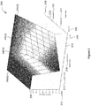
- Figure 2 illustrates an exemplary audio ducking function 200 performed by the audio processing system 100 of Figure 1 , according to various embodiments.
- the audio ducking function 200 is superimposed onto a 3-axis coordinate system, where the three axes include a speech level axis 210, a music level axis 220, and a desired music gain axis 230.
- the speech level axis 210 includes discrete levels for negligible speech 212, quieter speech 214, normal speech 216, and yelling 218.
- the music level axis 220 includes discrete levels for fortissimo (very loud) music 222, average music 224, pianissimo (very soft) music 226, and none (no music) 228. Although discrete levels are indicated on the speech level axis 210 and on the music level axis 220, both of these axes are continuous and include values between the discrete levels as shown.
- the desired music gain axis 230 indicates a multiplier to apply to the incoming music signal based on the speech level, as shown on the speech level axis 210, and on the music level, as shown on the music level axis 220.
- a value of 1 on the desired music gain axis 230 indicates that the incoming music is multiplied by 1
- a value of 0.9 on the desired music gain axis 230 indicates that the incoming music is multiplied by 0.9
- value of 0.8 on the desired music gain axis 230 indicates that the incoming music is multiplied by 0.8, and so on.
- a "unity" gain of 1.0 indicates no attenuation of the input music signal
- a “null” gain of 0.0 indicates heavy attenuation (e.g. 30dB) of the input music signal.
- Line segment 240(0) corresponding to a negligible speech level, the desired music gain is 1 regardless of the music level.
- Line segment 240(0) indicates that there is no attenuation of the music signal when the speech level is negligible. Therefore, the listener hears only the music signal.
- the desired music gain is approximately 0.18 when the music level is fortissimo.
- the desired music gain increases as the music level decreases until the desired music gain is 1 when there is no music signal.
- Line segment 240(1) indicates that a fortissimo music signal is significantly attenuated to ensure that a quieter speech level is audible over very loud music. Less attenuation is warranted for lower music levels, and no attenuation is needed when no music signal is present, such as during the silent gaps between songs.
- the prior ducking level may be maintained for a threshold period of time in order to prevent a change in ducking level between songs.
- the desired music gain is approximately 0.32 when the music level is fortissimo.
- the desired music gain increases as the music level decreases until the desired music gain is 1 when there is no music signal.
- Line segment 240(2) indicates that a fortissimo music signal is moderately attenuated to ensure that a normal speech level is audible over very loud music. Less attenuation is warranted for lower music levels, and no attenuation is needed when no music signal is present.
- the desired music gain is approximately 0.50 when the music level is fortissimo.
- the desired music gain increases as the music level decreases until the desired music gain is 1 when there is no music signal.
- Line segment 240(3) indicates that a fortissimo music signal is lightly attenuated to ensure that a loud level speech is audible over very loud music. Less attenuation is warranted for lower music levels, and no attenuation is needed when no music signal is present.
- the audio ducking function 200 illustrated in Figure 2 bases the desired music gain on both the speech level and the music level in order to adapt to various combinations of music and speech levels.
- the desired music gain increases as the music level decreases.
- the desired music gain remains constant as the speech level increases from negligible until quieter speech is detected.
- the desired music level then sharply decreases to a relatively low level and then gradually increases as the speech level increases from quieter speech to very loud speech.
- Figure 3 sets forth an exemplary set of waveforms 300 that illustrates the audio ducking function performed by the audio processing system 100 of Figure 1 , according to various embodiments.
- the set of waveforms 300 includes an input speech waveform 310, an input music waveform 320, and an output music waveform 330. These three waveforms are superimposed onto a 2-axis coordinate system.
- the vertical axis 340 indicates audio voltage level in dBu, a root mean square (RMS) measurement of voltage referenced to approximately 0.775 V RMS.
- the horizontal axis 350 indicates time in seconds.
- the input speech waveform 310 indicates that no speech (approximately -90 dBu input level) is present. During this period, no ducking occurs, and the level of the output music waveform 330 remains at the level of the input music waveform 320.
- the input speech waveform 310 indicates that speech is present at a level of -15 dBu. The input music level is ducked to a level that is 11 dB below the speech level. Because the input music level is at -16 dBu (below the input speech level), the level of the output music waveform 330 is ducked 10 dB to -26 dBu.
- the input speech waveform 310 indicates that speech is present at a quieter level of -27 dBu.
- the input music level is ducked 22dB to a level that is 11 dB below the speech level, or -38 dBu.
- the input speech waveform 310 indicates that speech is present at a quieter level of -27 dBu.
- the input music level is ducked to a level that is 11 dB below the speech level. Because the input music level is at -35 dBu (below the input speech level), the level of the output music waveform 330 is ducked 3 dB to -38 dBu.
- the rapid attack function allows the speech signal to pass through the listening device quickly to avoid cutting the initial portion of the speech signal.
- the long release function allows the audio ducking to release slowly, providing a less jarring experience for the listener and allowing for short gaps and pauses during speech before fully releasing the ducking function.
- FIGS 4A-4B set forth a flow diagram of method steps for processing entertainment signals and alert signals, according to various embodiments. Although the method steps are described in conjunction with the systems of Figures 1-3 , persons skilled in the art will understand that any system configured to perform the method steps, in any order, is within the scope of the present disclosure.
- a method 400 begins at step 402, where sound environment processor 130 receives environmental sound via a microphone input 105 and an entertainment signal via an audio input 110.
- the environmental sound represents the sound present in the environment of a listener.
- the entertainment signal represents music or other audio selected by the listener, such as music from an audio playback device.
- sound environment processor 130 performs noise reduction on the environmental sound to remove low-level, steady-state sounds from the microphone input 105 signal, such as traffic noise and low-level microphone hiss.
- the microphone RMS detector 145 calculates the RMS level of the voice separated sound received via the voice separator 135.
- audio input RMS detector 150 calculates the RMS level of the entertainment signal received via the audio input 110.
- voice separator 135 detects that a potential alert signal, such as human speech, is present in the microphone input signal.
- the voice separator 135 may perform this function by applying a first bandpass filter to the microphone input signal to generate a filtered microphone input signal.
- the voice separator 135 may calculate the RMS level associated with the filtered microphone input signal. If this RMS exceeds a threshold level, then an alert signal may be present in the microphone input signal.
- ambience separator 140 detects that ambient noise, such as background construction noise or background conversation noise, is present in the microphone input signal. Such ambient sound may still be present in the microphone input signal if the ambient noise is too loud or irregular to be filtered by noise reduction.
- the ambience separator 140 may perform this function by applying a second bandpass filter to the microphone input signal to generate a filtered microphone input signal.
- the ambience separator 140 may calculate the RMS level associated with the filtered microphone input signal.
- the first and second bandpass filters may have the same frequency response, but the response time for ambient RMS detection may be slower than the response time for microphone input RMS detection.
- voice activity detector 155 determines whether the RMS level of the potential alert signal, such as voice or human speech, exceeds the RMS level of the ambient sound. If the RMS level of the signal of interest does not exceed the RMS level of the ambient sound, then the method 400 proceeds to step 402, described above. If, on the other hand, the RMS level of the signal of interest exceeds the RMS level of the ambient sound, then the method 400 proceeds to step 414, where the voice activity detector 155 determines whether the RMS level of the potential alert signal, such as voice or human speech, exceeds a ducker threshold level. If the RMS level of the signal of interest does not exceed the ducker threshold level, then the method 400 proceeds to step 402, described above.
- step 418 ratio-based attenuator 165 determines whether the RMS level of the microphone input 105 exceeds the RMS level of the audio input 110 by at least a target difference, such as a voice-to-music ratio (VMR).
- VMR voice-to-music ratio
- the target difference may be a fixed value. In other embodiments, the target difference may be user adjustable, or may depend on the entertainment signal level or on the alert signal level. If the RMS level of the microphone input 105 exceeds the RMS level of the audio input 110 by at least the VMR, then the method 400 proceeds to step 402, described above.
- step 420 ratio-based attenuator 165 calculates a reduction amount for the audio input 110 such that the RMS level of the microphone input 105 equals the RMS level of the audio input by the target difference.
- attack/release logic 170 applies an attack/release profile to the audio input 110.
- attack/release logic 170 may apply a fast attack/slow release profile when presence or removal of an alert signal is first detected.
- Attack/release logic 170 may apply a slower attack/slower release profile when the alert signal has been present for a minimum duration of time.
- voltage controlled amplifier 175 attenuates the audio input 110 based on the level of ducking determined in the prior steps.
- mixer 180 combines the noise-reduced microphone input and the attenuated audio input.
- intelligent system monitor 160 determines that the alert signal is no longer present in the microphone input 105.
- intelligent system monitor 160 maintains the audio level of the audio input 110 at the attenuated level for a minimum duration of time.
- intelligent system monitor 160 causes the audio level of the audio input 110 to increase to the pre-adjusted level.
- the method 400 then proceeds to step 402, described above.
- the steps of method 400 may be performed in a continuous loop until certain events occur, such as powering down a device that includes the audio processing system 100.
- an audio processing system 100 combines environmental sound with an entertainment signal, such as music from an audio playback device, allowing the listener to continue to hear the entertainment signal at a reduced level relative to the environmental sound when an alert signal, such as speech, is present in the environmental sound.
- the audio processing system 100 attenuates or ducks the entertainment signal only enough to ensure that the alert signal is intelligible without attenuating the entertainment signal more than necessary, based on the levels of the entertainment signal and the alert signal.
- the audio processing system 100 receives a target voice-to-music (VMR) ratio, typically via a user control.
- the audio processing system 100 attenuates the entertainment signal just enough to maintain this target VMR ratio.
- the audio processing system 100 intelligently automatically detects the presence of an alert signal in noisy, loud, and complex sound environments, without end-user input or intervention.
- At least one advantage of the approach described herein is that a listener who uses the disclosed listening device equipped with the audio processing system 100 hears a high-quality audio signal from an audio playback device plus certain alert signals from the environmental sound, while, at the same time, other sounds from the environmental sound are suppressed relative to the alert signal.
- the entertainment signal is reduced only when an alert signal is present in the environment sound and only to the degree necessary to hear the alert signal.
- the listener hears alert signals from the environment along with an improved entertainment signal relative to prior approaches, leading to a better quality audio experience for the listener.
- aspects of the present embodiments may be embodied as a system, method or computer program product. Accordingly, aspects of the present disclosure may take the form of an entirely hardware embodiment, an entirely software embodiment (including firmware, resident software, micro-code, etc.) or an embodiment combining software and hardware aspects that may all generally be referred to herein as a "circuit,” “module” or “system.” Furthermore, aspects of the present disclosure may take the form of a computer program product embodied in one or more computer readable medium(s) having computer readable program code embodied thereon.
- the computer readable medium may be a computer readable signal medium or a computer readable storage medium.
- a computer readable storage medium may be, for example, but not limited to, an electronic, magnetic, optical, electromagnetic, infrared, or semiconductor system, apparatus, or device, or any suitable combination of the foregoing.
- a computer readable storage medium may be any tangible medium that can contain, or store a program for use by or in connection with an instruction execution system, apparatus, or device.
- each block in the flowchart or block diagrams may represent a module, segment, or portion of code, which comprises one or more executable instructions for implementing the specified logical function(s).
- the functions noted in the block may occur out of the order noted in the figures. For example, and without limitation, two blocks shown in succession may, in fact, be executed substantially concurrently, or the blocks may sometimes be executed in the reverse order, depending upon the functionality involved.
Description
- This application claims the benefit of United States provisional patent application titled, "APPROACH FOR PARTIALLY PRESERVING MUSIC IN THE PRESENCE OF INTELLIGIBLE SPEECH," filed on June 9, 2014 and having Serial No.
62/009,851 - Embodiments of the present disclosure relate generally to audio signal processing and, more specifically, to an approach for partially preserving music in the presence of intelligible speech.
- Headphones, earphones, earbuds, and other personal listening devices are commonly used by individuals who desire to listen to a particular type of audio source, such as music, speech, or movie soundtracks, without disturbing other people in the nearby vicinity. These types of audio sources are referred to herein as "entertainment" signals, and each is typically characterized as an audio signal that is present over a sustained period of time. Typically, these personal listening devices include an audio plug for insertion into an audio output of an audio playback device. The audio plug connects to a cable that carries the audio signal from the audio playback device to the personal listening device. In order to provide high quality audio, such personal listening devices include speaker components that typically cover the entire ear or completely seal the ear canal. The personal listening device is designed to provide a good acoustic seal, thereby reducing audio signal leakage and improving the quality of the listener's experience, particularly with respect to bass response.
- Document
US 2007/0189544 A1 discloses a method of adjusting an output of a media player comprising capturing an ambient audio signal, processing the ambient audio signal to determine whether one or more characteristic forms are present within the ambient audio signal, and reducing an output of a media player from a first volume to a second volume of the one or more characteristic forms are present within the ambient audio signal. The characteristic forms may be, for example, a name or personal identifier of a user of the media player, the voice of a user of the media player, or an alarm or siren. - Document
WO 2011/112382 A1 discloses a method and system for filtering a multi-channel audio signal having a speech channel and at least one non-speech channel, to improve intelligibility of speech determined by the signal. In typical embodiments, the method includes steps of determining at least one attenuation control value indicative of a measure of similarity between speech-related content determined by the speech channel and speech-related content determined by the non-speech channel, and attenuating the non-speech channel in response to the at least one attenuation control value. Typically, the attenuating step includes scaling of a raw attenuation control signal (e.g. ducking gain control signal) for the non-speech channel in response to the at least one attenuation control value. - Document
WO 2014/022359 A2 discloses an earphone system and method for automatically directing ambient sound to an earphone device. An ambient microphone signal from an ambient microphone proximate a sound isolating earphone or headset device is directed to a receiver within an earphone device according to mixing circuitry. The mixing circuitry is controlled by voice activity of the earphone device wearer. This enables hands-free operation of an earphone system to allow the earphone device wearer to maintain situation awareness with the surrounding environment. During detected voice activity, incoming audio content is attenuated while ambient sound is increased and provided to the earphone device. User voice activity is detected by analysis of at least one of an ear canal microphone signal or an ambient sound microphone signal. - One drawback of the personal listening devices described above is that, because the devices form a good acoustic seal with the ear, the ability of the listener to hear environmental sound is substantially reduced. As a result, the listener may be unable to hear certain important sounds from the environment, such as the sound of an oncoming vehicle, human speech, or an alarm. These types of important sounds emanating from the environment are referred to herein as "priority" or "alert" signals, and each is typically characterized as an audio signal that is intermittent, acting as an interruption.
- One solution to the above problem is to acoustically or electronically mix or combine environmental sound, including any alert signal present in the environmental sound, detected by one or more microphones with the entertainment signal. The listener is then able to hear both the entertainment signal and the environmental sound, including any alert signal. One drawback with such solutions, though, is that the alert signal may be unintelligible (or may even be inaudible) if the entertainment signal is too loud relative to the alert signal.
- As the foregoing illustrates, more effective techniques for providing entertainment signals and alert signals to users of listening devices would be useful.
- One or more embodiments set forth an audio processing system for a listening device that includes an input device, a voice activity detector and a ratio-based attenuator. The input device is configured to receive a first audio signal emanating from an environment and including a signal of interest. The voice activity detector is configured to receive a first control signal from a voice separator, determine that the signal of interest is present in the first audio signal by determining that the first control signal exceeds a ducker threshold, and generate a second control signal in response to the first audio signal. The ratio-based attenuator is configured to receive the second control signal from the voice activity detector. The ratio-based attenuator is further configured to determine whether a first signal level associated with the first audio signal exceeds a second signal level associated with a second audio signal received from an audio playback device by at least a target difference. The ratio-based attenuator is further configured to, if the first signal level exceeds the second signal level by at least a target difference, then maintain an audio level of the second audio signal. The ratio-based attenuator is further configured to if the first signal level does not exceed the second signal level by at least the target difference, then cause the audio level of the second audio signal to be adjusted from a first value to a second value, wherein, at the second value, the first signal level exceeds the second signal level by at least the target difference.
- Other embodiments include, without limitation, a computer readable medium including instructions for performing one or more aspects of the disclosed techniques, as well as a method for performing one or more aspects of the disclosed techniques.
- At least one advantage of the disclosed approach is that a listener who uses the disclosed listening device equipped with the
audio processing system 100 hears a high-quality audio signal from an audio playback device plus certain alert signals from the environmental sound, while, at the same time, other sounds from the environmental sound are suppressed relative to the alert signal. - So that the manner in which the above recited features of embodiments of the invention can be understood in detail, a more particular description of the invention, briefly summarized above, may be had by reference to embodiments, some of which are illustrated in the appended drawings. It is to be noted, however, that the appended drawings illustrate only typical embodiments of this invention and are therefore not to be considered limiting of its scope, for the invention may admit to other equally effective embodiments.
-
Figure 1 illustrates an audio processing system configured to implement one or more aspects of the various embodiments; -
Figure 2 illustrates an exemplary audio ducking function performed by the audio processing system ofFigure 1 , according to various embodiments; -
Figure 3 sets forth an exemplary set of waveforms that illustrates the audio ducking function performed by the audio processing system ofFigure 1 , according to various embodiments; and -
Figures 4A-4B set forth a flow diagram of method steps for processing entertainment signals and alert signals, according to various embodiments. - In the following description, numerous specific details are set forth to provide a more thorough understanding of certain specific embodiments. However, it will be apparent to one of skill in the art that other embodiments may be practiced without one or more of these specific details or with additional specific details.
- As described herein, an audio processing system in a listening device determines when an alert signal is present in the environmental sound and, in response, intelligently attenuates or ducks the audio level of an entertainment signal to maintain a voice-to-music ratio (VMR) at or near a target value. Stated another way, the audio processing system maintains a relatively constant alert signal level to entertainment signal level ratio (AER). Although the disclosed techniques are described in the context of a personal listening device, the techniques may also be applied to other audio systems, including, without limitation, a public address system. In general, the entertainment signal level corresponds to the volume setting on a playback device as set by a listener. The alert signal level corresponds to the strength of a signal of interest, such as speech, present in the environment. In one example, and without limitation, a low alert signal level could result from a soft-spoken server at a restaurant announcing that the table is ready. If the server's announcement is quieter than the voices of patrons, other servers, or the maître d', the entertainment signal is more heavily attenuated so that the server's voice can be heard. In another example, and without limitation, a low alert signal level could result from a fellow cyclist speaking at some distance away from the listener wearing earbuds that include microphones. Because sound levels are reduced over space due to acoustic spreading, a cyclist who is 20 feet away from the listener sounds quieter than a cyclist who is 6 feet away. As a result, the amount of ducking applied to the entertainment signal increases as the strength of the entertainment signal increases. However, the amount of ducking applied to the entertainment signal decreases as the strength of the alert signal increases.
- The audio processing system applies intelligent ducking when an alert signal is actually present in the environment audio and is sufficiently loud. Therefore, if there is no alert signal or if a signal of interest, referred to herein as a potential alert signal, is at a negligible level, then audio processing system does not apply ducking to the entertainment signal. As a result, low-level, steady-state background sounds, such as distant, quiet, conversations at a large distance, are prevented from engaging the ducking system. This audio processing system is now described in greater detail.
-
Figure 1 illustrates anaudio processing system 100 configured to implement one or more aspects of the various embodiments. As shown,audio processing system 100 includes, without limitation,sound environment processor 130,voice separator 135,ambience separator 140, microphone root-mean square (RMS)detector 145, audioinput RMS detector 150,voice activity detector 155, ratio-basedattenuator 165, intelligent system monitor 160,attack release logic 170, voltage controlledamplifier 175, andmixer 180. -
Sound environment processor 130 receives a microphone (mic)input signal 105 from one or more microphones that capture sound emanating from the environment. In some embodiments,sound environment processor 130 receives sound emanating from the environment electronically rather than via one or more microphones.Sound environment processor 130 performs noise reduction on the microphone input.Sound environment processor 130 cleans and enhances the microphone input by removing one or more noise signals, including, without limitation, microphone (mic) hiss, steady-state noise, very low frequency sounds (such as traffic din), and other low-level, steady-state sounds, while leaving intact any potential alert signal. In general, a low-level sound is a sound with a signal level that is below a threshold of loudness. In some embodiments, a gate may be used to remove such low-level signals from the input signal before transmitting the processed signal as an output. In general, a steady-state sound is a sound with a signal amplitude that remains relatively constant over time, in contrast to a transient sound with a signal amplitude that changes over time. In one example, and without limitation, the sound of an idling car could be considered a steady-state sound while the sound of an accelerating car or a car with a revving engine would not be considered a steady-state sound. In another example, and without limitation, the sound of operatic singing could be considered a steady-state sound while the sound of speech would not be considered a steady-state sound. In yet another example, and without limitation, the sound of very slow, symphonic music could be considered a steady-state sound while the sound of relatively faster, percussive music would not be considered a steady-state sound. The potential alert signal includes sounds that are not low-level, steady-state sound, such as human speech or an automobile horn.Sound environment processor 130 transmits a high-fidelity noise-reduced signal tomixer 180.Sound environment processor 130 also transmits a control signal to voiceseparator 135,ambience separator 140, andmicrophone RMS detector 145. In some embodiments, each of the control signals transmitted tovoice separator 135,ambience separator 140, andmicrophone RMS detector 145 may be identical copies of the same signal. The control signal may be a lower fidelity version of the noise-reduced audio that is transmitted tomixer 180. -
Voice separator 135 receives a control signal fromsound environment processor 130.Voice separator 135 extracts any potential alert signal, such as speech, that is present in the received control signal. In some embodiments,voice separator 135 performs this function by applying a bandpass filter followed by an RMS detector to detect voice signals and other transient signals. In some embodiments,voice separator 135 may determine that audio energy in the range of 500 Hz to 3,000 Hz is considered to be a potential alert signal. In these embodiments, the output fromvoice separator 135 may be the RMS level of the audio energy in the range of 500 Hz to 3,000 Hz. If the RMS level of the audio in this frequency range exceeds a given threshold,voice separator 135 may determine that a potential alert signal is present.Voice separator 135 transmits a control signal to voiceactivity detector 155. -
Ambience separator 140 is an optional module that receives a control signal fromsound environment processor 130.Ambience separator 140 compares the RMS level of the microphone input against a threshold level to detect ambient signals, such as traffic noise, construction noise and other background noise, that pass throughsound environment processor 130. In some embodiments,ambience separator 140 performs this function via a feature extraction approach.Ambience separator 140 transmits a control signal to voiceactivity detector 155. -
Microphone RMS detector 145 receives a control signal fromvoice separator 135.Microphone RMS detector 145 detects the root mean square (RMS) level of the processed microphone input signal received fromvoice separator 135.Microphone RMS detector 145 calculates the energy of the processed microphone input signal in the log (dB units) domain. In some embodiments,microphone RMS detector 145 may employ an alternative signal level measurement technique other than detecting the RMS level of the signal. In one example, and without limitation,microphone RMS detector 145 employs a more sophisticated psychoacoustic signal level measurement technique.Microphone RMS detector 145 transmits a control signal, corresponding to the detected microphone RMS level, to ratio-basedattenuator 165. - Audio
input RMS detector 150 receives an entertainment signal from an audio playback device viaaudio input 110. Audioinput RMS detector 150 detects the root mean square (RMS) level of the entertainment signal received viaaudio input 110. Audioinput RMS detector 150 calculates the energy of the entertainment signal in the log (dB units) domain. In some embodiments,audio RMS detector 150 may employ an alternative signal level measurement technique other than detecting the RMS level of the signal. In one example, and without limitation,audio RMS detector 150 employs a more sophisticated psychoacoustic signal level measurement technique. Audioinput RMS detector 150 transmits a control signal, corresponding to the calculated entertainment signal input RMS level, to ratio-basedattenuator 165. -
Voice activity detector 155 receives control signals fromvoice separator 135,ambience separator 140, and intelligent system monitor 160.Voice activity detector 155 analyzes the received control signals fromvoice separator 135 andambience separator 140 and compares these two control signals against aducker threshold 115 to detect the presence of an alert signal and, if an alert signal is present, whether or not to duck the entertainment audio received viaaudio input 110. In some embodiments, theducker threshold 115 may be set via a user control.Voice activity detector 155 determines that an alert signal is present when the control signal received fromvoice separator 135 exceeds theducker threshold 115. Whenambience separator 140 is present,voice activity detector 155 further determines that an alert signal is present when the control signal received fromvoice separator 135 includes an alert signal thatambience separator 140 does not identify as an ambient signal. As a result,voice activity detector 155 reduces the likelihood that louder, low-frequency, steady-state sounds are misclassified as alert signals. - In some embodiments, if
voice activity detector 155 determines that an alert signal is present,voice activity detector 155 may calculate a control signal based on the ratio of the signal fromvoice separator 135 versus theducker threshold 115 Ifvoice activity detector 155 determines that no alert signal is present, then voiceactivity detector 155 may set this control signal to 1, that is, unity gain, to inhibit ducking of theaudio input 110. As further discussed herein, whenvoice activity detector 155 determines that an alert signal is no longer present,voice activity 155 continues to apply ducking during a ducking hold signal received from intelligent system monitor 160.Voice activity detector 155 transmits a control signal to intelligent system monitor 160 and to ratio-basedattenuator 165. - Intelligent system monitor 160 receives a control signal from
voice activity detector 155. Intelligent system monitor 160 determines the duration of ducking and the speed of ducking, based on the received control signal. As one example, and without limitation, human speech could vary in volume, where some portions of the human speech could be louder while other portions of the human speech are quieter. In addition, no human speech would be present between words or during short pauses. In such cases, audio ducking could be applied and removed multiple times during speech. Consequently, the entertainment signal present onaudio input 110 would be ducked and released from ducking in rapid succession, resulting in an unpleasant listener experience. Intelligent system monitor 160 could effectively apply a hold time to maintain a ducking function for a threshold duration of time after an alert signal is no longer present at themicrophone input 105. As a result, ducking would be maintained over short gaps, such as between words or short pauses, but ducking would be released when a relatively long pause is detected. - In some embodiments, intelligent system monitor 160 may determine that duration of ducking may be zero, resulting in no ducking. Intelligent system monitor 160 generates a control signal that identifies when ducking hold time should be applied. Intelligent system monitor 160 transmits the control signal to voice
activity detector 155 and attack/release logic 170. Intelligent system monitor 160 optionally transmits the control signal to ratio-basedattenuator 165. - Ratio-based
attenuator 165 receives RMS audio levels frommicrophone RMS detector 145 and audioinput RMS detector 150. Ratio-basedattenuator 165 also receives control signals fromvoice activity detector 155 and optionally from intelligent system monitor 160. Ratio-basedattenuator 165 determines the amount of gain reduction to be applied to the entertainment signal received viaaudio input 110. Ratio-basedattenuator 165 receives a voice-to-music ratio (VMR) 120 that specifies a target level by which theaudio input 110 is ducked relative to themicrophone input 105. In some embodiments, theVMR 120 may be set via a user control. For example, and without limitation, if theVMR 120 is set to -30 dB and ducking is applied, then ratio-basedattenuator 165 sets the attenuation of the signal received ataudio input 110 so that the level ofaudio input 110 is at least -30 dB relative to themicrophone input 105. If the control signal from intelligent system monitor 160 indicates that ducking hold time is applied, then ratio-basedattenuator 165 maintains the most recent ducking level until the ducking hold is removed. During ducking hold time, ratio-basedattenuator 165 neither increases nor decreases the ducking level. Ratio-basedattenuator 165 generates a control signal that indicates the amount that theaudio input 110 signal is to be ducked. In general, ratio-basedattenuator 165 modifies the level of the entertainment signal via attenuation, rather than amplification, so the gain of the entertainment signal does not exceed unity. Ratio-basedattenuator 165 transmits this control signal to attack/release logic 170. - Attack/
release logic 170 receives control signals from intelligent system monitor 160 and ratio-basedattenuator 165. Based on these control signals, attack/release logic 170 applies a smoothing function to the gain reduction resulting from ducking in order to prevent undesirable modulation of the entertainment signal received viaaudio input 110. In some embodiments, attack/release logic 170 may employ asymmetric attack and release profiles, such as a relatively fast attack profile and a relatively slower release profile. Attack/release logic 170 applies a fast attack to quickly duck theaudio input 110 signal when a new alert signal is detected in order to avoid cutting off the beginning of the alert signal and, thereby, preserve the intelligibility of speech. Attack/release logic 170 applies a relatively slower release to avoid abrupt changes to the entertainment signal when an alert signal is no longer detected. - Additionally, in some embodiments, attack/
release logic 170 may apply a hysteresis logic to prevent undesirable modulation of the entertainment signal when the ducker is engaged. Via this hysteresis logic, attack/release logic 170 employs a slower attack/slower release profile when audio ducking is near the target ducking level, based on the control signal received from intelligent system monitor 160. This control signal indicates whether an alert signal has recently appeared or disappeared in themicrophone input 105 signal, or whether the signal of interest has been present for a threshold duration of time. If an alert signal has recently appeared or disappeared, then attack/release logic 170 applies a fast attack/slow release profile. If, on the other hand, an alert signal has been present for a threshold period of time, then attack/release logic 170 applies a slower attack/slower release profile. The slower attack/slower release profile still responds to changes in RMS levels received from themicrophone input 105 andaudio input 110, but at a slower response rate relative to the fast attack/slow release profile. Attack/release logic 170 transmits a smoothed gain control signal to voltage controlledamplifier 175. - Voltage controlled
amplifier 175 receives a smoothed gain control signal from attack/release logic 170. Voltage controlledamplifier 175 receives the entertainment signal via theaudio input 110. Voltage controlledamplifier 175 applies the smoothed gain control signal to the entertainment signal to generate a ducked entertainment signal. When audio ducking is applied, voltage controlledamplifier 175 applies more attenuation to the entertainment signal when the entertainment signal received via theaudio input 110 is relatively louder or when the alert signal received via themicrophone input 105 is relatively quieter. When no audio ducking is applied, voltage controlledamplifier 175 passes the entertainment signal received via theaudio input 110 without attenuation. Voltage controlledamplifier 175 passes the resulting ducked entertainment signal tomixer 180. -
Mixer 180 receives noise-reduced microphone audio fromsound environment processor 130 and the ducked entertainment signal from voltage controlledamplifier 175.Mixer 180 mixes or combines the two received audio signals to generate an output signal. In some embodiments,mixer 180 may perform a simple additive or multiplicative mix on the two audio signals. In other embodiments,mixer 180 may perform any technically feasible mix or combine function on the two audio signals.Mixer 180 transmits the output signal to one or more speakers viaaudio output 125. - In various embodiments,
audio processing system 100 may be implemented as a state machine, a central processing unit (CPU), digital signal processor (DSP), a microcontroller, an application-specific integrated circuit (ASIC), or any device or structure configured to process data and execute software applications. In some embodiments, one or more of the blocks illustrated inFigure 1 may be implemented with discrete analog or digital circuitry. In one example, and without limitation, the voltage controlledamplifier 175 andmixer 180 could be implemented with analog components.Audio processing system 100 may be associated with a mobile computer, dash-mounted device, personal digital assistant, mobile phone, wearable device, mobile device or any other device suitable for practicing one or more embodiments of the present invention.Audio processing system 100 may be configured to implement an intelligentaudio processing system 100, as further described herein. Thisaudio processing system 100 may be implemented in any technically feasible form factor, including, without limitation, headphones or ear buds with situational awareness (e.g via microphones), broadcast systems, interruptible foldback (IFB) systems, or paging systems. -
Figure 2 illustrates an exemplaryaudio ducking function 200 performed by theaudio processing system 100 ofFigure 1 , according to various embodiments. As shown, and without limitation, theaudio ducking function 200 is superimposed onto a 3-axis coordinate system, where the three axes include aspeech level axis 210, amusic level axis 220, and a desiredmusic gain axis 230. - The
speech level axis 210 includes discrete levels fornegligible speech 212,quieter speech 214,normal speech 216, and yelling 218. Similarly, themusic level axis 220 includes discrete levels for fortissimo (very loud)music 222,average music 224, pianissimo (very soft)music 226, and none (no music) 228. Although discrete levels are indicated on thespeech level axis 210 and on themusic level axis 220, both of these axes are continuous and include values between the discrete levels as shown. The desiredmusic gain axis 230 indicates a multiplier to apply to the incoming music signal based on the speech level, as shown on thespeech level axis 210, and on the music level, as shown on themusic level axis 220. A value of 1 on the desiredmusic gain axis 230 indicates that the incoming music is multiplied by 1, a value of 0.9 on the desiredmusic gain axis 230 indicates that the incoming music is multiplied by 0.9, value of 0.8 on the desiredmusic gain axis 230 indicates that the incoming music is multiplied by 0.8, and so on. As shown, A "unity" gain of 1.0 (dark red) indicates no attenuation of the input music signal, and a "null" gain of 0.0 (dark blue) indicates heavy attenuation (e.g. 30dB) of the input music signal. - Following the line segment 240(0), corresponding to a negligible speech level, the desired music gain is 1 regardless of the music level. Line segment 240(0) indicates that there is no attenuation of the music signal when the speech level is negligible. Therefore, the listener hears only the music signal.
- Following the line segment 240(1), corresponding to a quieter speech level, the desired music gain is approximately 0.18 when the music level is fortissimo. The desired music gain increases as the music level decreases until the desired music gain is 1 when there is no music signal. Line segment 240(1) indicates that a fortissimo music signal is significantly attenuated to ensure that a quieter speech level is audible over very loud music. Less attenuation is warranted for lower music levels, and no attenuation is needed when no music signal is present, such as during the silent gaps between songs. In one embodiment, when no music signal is present, the prior ducking level may be maintained for a threshold period of time in order to prevent a change in ducking level between songs.
- Following the line segment 240(2), corresponding to a normal speech level, the desired music gain is approximately 0.32 when the music level is fortissimo. The desired music gain increases as the music level decreases until the desired music gain is 1 when there is no music signal. Line segment 240(2) indicates that a fortissimo music signal is moderately attenuated to ensure that a normal speech level is audible over very loud music. Less attenuation is warranted for lower music levels, and no attenuation is needed when no music signal is present.
- Following the line segment 240(3), corresponding to a very loud speech level, such as yelling, the desired music gain is approximately 0.50 when the music level is fortissimo. The desired music gain increases as the music level decreases until the desired music gain is 1 when there is no music signal. Line segment 240(3) indicates that a fortissimo music signal is lightly attenuated to ensure that a loud level speech is audible over very loud music. Less attenuation is warranted for lower music levels, and no attenuation is needed when no music signal is present.
- The
audio ducking function 200 illustrated inFigure 2 bases the desired music gain on both the speech level and the music level in order to adapt to various combinations of music and speech levels. In general, the desired music gain increases as the music level decreases. The desired music gain remains constant as the speech level increases from negligible until quieter speech is detected. The desired music level then sharply decreases to a relatively low level and then gradually increases as the speech level increases from quieter speech to very loud speech. -
Figure 3 sets forth an exemplary set ofwaveforms 300 that illustrates the audio ducking function performed by theaudio processing system 100 ofFigure 1 , according to various embodiments. As shown, and without limitation, the set ofwaveforms 300 includes aninput speech waveform 310, aninput music waveform 320, and anoutput music waveform 330. These three waveforms are superimposed onto a 2-axis coordinate system. Thevertical axis 340 indicates audio voltage level in dBu, a root mean square (RMS) measurement of voltage referenced to approximately 0.775 V RMS. Thehorizontal axis 350 indicates time in seconds. - The input music level, as shown by
input music waveform 320 begins at -16 dBu during the time interval t=0 to t=30. The input music level reduces to -35 dBu during the time interval t=30 to t=60. The input music level reduces further to -75 dBu during the time interval t=60 to t=90. - During the time interval t=0 to t=5, the
input speech waveform 310 indicates that no speech (approximately -90 dBu input level) is present. During this period, no ducking occurs, and the level of theoutput music waveform 330 remains at the level of theinput music waveform 320. During the time period t=5 to t=10, theinput speech waveform 310 indicates that speech is present at a level of -15 dBu. The input music level is ducked to a level that is 11 dB below the speech level. Because the input music level is at -16 dBu (below the input speech level), the level of theoutput music waveform 330 is ducked 10 dB to -26 dBu. During the time period t=10 to t=20, no speech (approximately -90 dBu input level) is present, and the ducking function is released, allowing the output music level to return to the -16 dBu level. During the time period t=20 to t=25, theinput speech waveform 310 indicates that speech is present at a quieter level of -27 dBu. The input music level is ducked 22dB to a level that is 11 dB below the speech level, or -38 dBu. - During the time interval t=25 to t=35, the
input speech waveform 310 indicates that no speech (approximately -90 dBu input level) is present. During this period, no ducking occurs, and the level of theoutput music waveform 330 returns to the level of theinput music waveform 320. At time t=30, the input music level, and, correspondingly, the output music level, is reduced to -35 dBu. During the time period t=35 to t=40, theinput speech waveform 310 indicates that speech is present at a level of -15 dBu. Because the input music level is already more than 11 dB below the speech level, no ducking occurs. During the time period t=40 to t=50, no speech (approximately -90 dBu input level) is present, and the output music level remains at the input music level of -35 dBu. During the time period t=50 to t=55, theinput speech waveform 310 indicates that speech is present at a quieter level of -27 dBu. The input music level is ducked to a level that is 11 dB below the speech level. Because the input music level is at -35 dBu (below the input speech level), the level of theoutput music waveform 330 is ducked 3 dB to -38 dBu. - During the time interval t=55 to t=65, the
input speech waveform 310 indicates that no speech (approximately -90 dBu input level) is present. During this period, no ducking occurs, and the level of theoutput music waveform 330 returns to the level of theinput music waveform 320. At time t=60, the input music level, and, correspondingly, the output music level, is reduced to -75 dBu. During the time period t=65 to t=70, theinput speech waveform 310 indicates that speech is present at a level of -15 dBu. Because the input music level is already more than 11 dB below the speech level, no ducking occurs. During the time period t=70 to t=80, no speech (approximately -90 dBu input level) is present, and the output music level remains at the input music level of -75 dBu. During the time period t=80 to t=85, theinput speech waveform 310 indicates that speech is present at a quieter level of -27 dBu. Again, the input music level is already more than 11 dB below the speech level, and no ducking occurs. Finally, during the time period t=85 to t=90, no speech (approximately -90 dBu input level) is present, and the output music level remains at the input music level of -75 dBu. - Note that the
output music waveform 330 indicates a fast attack time when applying ducking at t=5, t=20, and t=50, as illustrated by the relatively short fall time. Theoutput music waveform 330 indicates a slower release time when releasing ducking at t=10, t=25, and t=55, as illustrated by the longer rise time. The rapid attack function allows the speech signal to pass through the listening device quickly to avoid cutting the initial portion of the speech signal. The long release function allows the audio ducking to release slowly, providing a less jarring experience for the listener and allowing for short gaps and pauses during speech before fully releasing the ducking function. -
Figures 4A-4B set forth a flow diagram of method steps for processing entertainment signals and alert signals, according to various embodiments. Although the method steps are described in conjunction with the systems ofFigures 1-3 , persons skilled in the art will understand that any system configured to perform the method steps, in any order, is within the scope of the present disclosure. - As shown, a
method 400 begins atstep 402, wheresound environment processor 130 receives environmental sound via amicrophone input 105 and an entertainment signal via anaudio input 110. The environmental sound represents the sound present in the environment of a listener. The entertainment signal represents music or other audio selected by the listener, such as music from an audio playback device. Atstep 404,sound environment processor 130 performs noise reduction on the environmental sound to remove low-level, steady-state sounds from themicrophone input 105 signal, such as traffic noise and low-level microphone hiss. Atstep 406, themicrophone RMS detector 145 calculates the RMS level of the voice separated sound received via thevoice separator 135. At step 408, audioinput RMS detector 150 calculates the RMS level of the entertainment signal received via theaudio input 110. - At
step 410,voice separator 135 detects that a potential alert signal, such as human speech, is present in the microphone input signal. In some embodiments, thevoice separator 135 may perform this function by applying a first bandpass filter to the microphone input signal to generate a filtered microphone input signal. Thevoice separator 135 may calculate the RMS level associated with the filtered microphone input signal. If this RMS exceeds a threshold level, then an alert signal may be present in the microphone input signal. - At
step 412,ambience separator 140 detects that ambient noise, such as background construction noise or background conversation noise, is present in the microphone input signal. Such ambient sound may still be present in the microphone input signal if the ambient noise is too loud or irregular to be filtered by noise reduction. In some embodiments, theambience separator 140 may perform this function by applying a second bandpass filter to the microphone input signal to generate a filtered microphone input signal. Theambience separator 140 may calculate the RMS level associated with the filtered microphone input signal. The first and second bandpass filters may have the same frequency response, but the response time for ambient RMS detection may be slower than the response time for microphone input RMS detection. - At
step 414,voice activity detector 155 determines whether the RMS level of the potential alert signal, such as voice or human speech, exceeds the RMS level of the ambient sound. If the RMS level of the signal of interest does not exceed the RMS level of the ambient sound, then themethod 400 proceeds to step 402, described above. If, on the other hand, the RMS level of the signal of interest exceeds the RMS level of the ambient sound, then themethod 400 proceeds to step 414, where thevoice activity detector 155 determines whether the RMS level of the potential alert signal, such as voice or human speech, exceeds a ducker threshold level. If the RMS level of the signal of interest does not exceed the ducker threshold level, then themethod 400 proceeds to step 402, described above. If, on the other hand, the RMS level of the signal of interest exceeds the ducker threshold level, then themethod 400 proceeds to step 418, where ratio-basedattenuator 165 determines whether the RMS level of themicrophone input 105 exceeds the RMS level of theaudio input 110 by at least a target difference, such as a voice-to-music ratio (VMR). In some embodiments, the target difference may be a fixed value. In other embodiments, the target difference may be user adjustable, or may depend on the entertainment signal level or on the alert signal level. If the RMS level of themicrophone input 105 exceeds the RMS level of theaudio input 110 by at least the VMR, then themethod 400 proceeds to step 402, described above. If, on the other hand, the RMS level of themicrophone input 105 does not exceed the RMS level of theaudio input 110 by at least a target difference, then themethod 400 proceeds to step 420, where ratio-basedattenuator 165 calculates a reduction amount for theaudio input 110 such that the RMS level of themicrophone input 105 equals the RMS level of the audio input by the target difference. - At
step 422, attack/release logic 170 applies an attack/release profile to theaudio input 110. In some embodiments, attack/release logic 170 may apply a fast attack/slow release profile when presence or removal of an alert signal is first detected. Attack/release logic 170 may apply a slower attack/slower release profile when the alert signal has been present for a minimum duration of time. Atstep 424, voltage controlledamplifier 175 attenuates theaudio input 110 based on the level of ducking determined in the prior steps. Atstep 426,mixer 180 combines the noise-reduced microphone input and the attenuated audio input. - At
step 428, intelligent system monitor 160 determines that the alert signal is no longer present in themicrophone input 105. Atstep 430, intelligent system monitor 160 maintains the audio level of theaudio input 110 at the attenuated level for a minimum duration of time. Atstep 432, after expiration of the minimum duration of time, intelligent system monitor 160 causes the audio level of theaudio input 110 to increase to the pre-adjusted level. Themethod 400 then proceeds to step 402, described above. In various embodiments, the steps ofmethod 400 may be performed in a continuous loop until certain events occur, such as powering down a device that includes theaudio processing system 100. - In sum, an
audio processing system 100 combines environmental sound with an entertainment signal, such as music from an audio playback device, allowing the listener to continue to hear the entertainment signal at a reduced level relative to the environmental sound when an alert signal, such as speech, is present in the environmental sound. Theaudio processing system 100 attenuates or ducks the entertainment signal only enough to ensure that the alert signal is intelligible without attenuating the entertainment signal more than necessary, based on the levels of the entertainment signal and the alert signal. Theaudio processing system 100 receives a target voice-to-music (VMR) ratio, typically via a user control. Theaudio processing system 100 attenuates the entertainment signal just enough to maintain this target VMR ratio. Theaudio processing system 100 intelligently automatically detects the presence of an alert signal in noisy, loud, and complex sound environments, without end-user input or intervention. - At least one advantage of the approach described herein is that a listener who uses the disclosed listening device equipped with the
audio processing system 100 hears a high-quality audio signal from an audio playback device plus certain alert signals from the environmental sound, while, at the same time, other sounds from the environmental sound are suppressed relative to the alert signal. The entertainment signal is reduced only when an alert signal is present in the environment sound and only to the degree necessary to hear the alert signal. As a result, the listener hears alert signals from the environment along with an improved entertainment signal relative to prior approaches, leading to a better quality audio experience for the listener. - The descriptions of the various embodiments have been presented for purposes of illustration, but are not intended to be exhaustive or limited to the embodiments disclosed. Many modifications and variations will be apparent to those of ordinary skill in the art without departing from the scope of the described embodiments. The scope of the invention is defined by the appended claims.
- Aspects of the present embodiments may be embodied as a system, method or computer program product. Accordingly, aspects of the present disclosure may take the form of an entirely hardware embodiment, an entirely software embodiment (including firmware, resident software, micro-code, etc.) or an embodiment combining software and hardware aspects that may all generally be referred to herein as a "circuit," "module" or "system." Furthermore, aspects of the present disclosure may take the form of a computer program product embodied in one or more computer readable medium(s) having computer readable program code embodied thereon.
- Any combination of one or more computer readable medium(s) may be utilized. The computer readable medium may be a computer readable signal medium or a computer readable storage medium. A computer readable storage medium may be, for example, but not limited to, an electronic, magnetic, optical, electromagnetic, infrared, or semiconductor system, apparatus, or device, or any suitable combination of the foregoing. More specific examples (a non-exhaustive list) of the computer readable storage medium would include the following: an electrical connection having one or more wires, a portable computer diskette, a hard disk, a random access memory (RAM), a read-only memory (ROM), an erasable programmable read-only memory (EPROM or Flash memory), an optical fiber, a portable compact disc read-only memory (CD-ROM), an optical storage device, a magnetic storage device, or any suitable combination of the foregoing. In the context of this document, a computer readable storage medium may be any tangible medium that can contain, or store a program for use by or in connection with an instruction execution system, apparatus, or device.
- Aspects of the present disclosure are described above with reference to flowchart illustrations and/or block diagrams of methods, apparatus (systems) and computer program products according to embodiments of the disclosure. It will be understood that each block of the flowchart illustrations and/or block diagrams, and combinations of blocks in the flowchart illustrations and/or block diagrams, can be implemented by computer program instructions. These computer program instructions may be provided to a processor of a general purpose computer, special purpose computer, or other programmable data processing apparatus to produce a machine, such that the instructions, which execute via the processor of the computer or other programmable data processing apparatus, enable the implementation of the functions/acts specified in the flowchart and/or block diagram block or blocks. Such processors may be, without limitation, general purpose processors, special-purpose processors, application-specific processors, or field-programmable
- The flowchart and block diagrams in the Figures illustrate the architecture, functionality, and operation of possible implementations of systems, methods and computer program products according to various embodiments of the present disclosure. In this regard, each block in the flowchart or block diagrams may represent a module, segment, or portion of code, which comprises one or more executable instructions for implementing the specified logical function(s). It should also be noted that, in some alternative implementations, the functions noted in the block may occur out of the order noted in the figures. For example, and without limitation, two blocks shown in succession may, in fact, be executed substantially concurrently, or the blocks may sometimes be executed in the reverse order, depending upon the functionality involved. It will also be noted that each block of the block diagrams and/or flowchart illustration, and combinations of blocks in the block diagrams and/or flowchart illustration, can be implemented by special purpose hardware-based systems that perform the specified functions or acts, or combinations of special purpose hardware and computer instructions.
- While the preceding is directed to embodiments of the present disclosure, other and further embodiments of the disclosure may be devised without departing from the basic scope thereof, and the scope thereof is determined by the claims that follow.
Claims (15)
- An audio processing system (100), comprising:an input device configured to receive a first audio signal (105) emanating from an environment and including a signal of interest;a voice activity detector (155) configured to:receive a first control signal from a voice separator (135),determine that the signal of interest is present in the first audio signal (105) by determining that the first control signal exceeds a ducker threshold, andgenerate a second control signal in response to the first audio signal (105); anda ratio-based attenuator (165) configured to:receive the second control signal from the voice activity detector (155),determine whether a first signal level associated with the first audio signal (105) exceeds a second signal level associated with a second audio signal (110) received from an audio playback device by at least a target difference, andif the first signal level exceeds the second signal level by at least a target difference, then maintain an audio level of the second audio signal, andif the first signal level does not exceed the second signal level by at least the target difference, then cause the audio level of the second audio signal (110) to be adjusted from a first value to a second value, wherein, at the second value, the first signal level exceeds the second signal level by at least the target difference.
- The audio processing system (100) of claim 1, further comprising a sound environment analyzer (130) configured to perform one or more noise reduction operations on the first audio signal (105) to remove a noise signal from the first audio signal (105).
- The audio processing system (100) of claim 1 or 2, further comprising the voice separator (135) configured to:apply a first bandpass filter to the first audio signal (105) to generate a first filtered audio signal;calculate a third signal level associated with the first filtered audio signal; andgenerate the first control signal based on the third signal level.
- The audio processing system (100) of claim 3, further comprising an ambience separator (140) configured to:apply a second bandpass filter to the first audio signal (105) to generate a second filtered audio signal;calculate a fourth signal level associated with the second filtered audio signal; andgenerate a third control signal based on the fourth signal level.
- The audio processing system (100) of claim 4, wherein the first bandpass filter and the second bandpass filter have substantially the same frequency range.
- The audio processing system (100) of claim 4, wherein the voice activity detector (155) is further configured to:receive the third control signal from the ambience separator (140); andfurther determine that the signal of interest is present in the first audio signal (105) by determining that the first control signal also exceeds the third control signal.
- The audio processing system (100) of any of claims 1 - 6, further comprising:a first signal level detector configured to calculate the first signal level; anda second signal level detector configured to calculate the second signal level.
- The audio processing system (100) of any of claims 1-7, wherein the ratio-based attenuator (165) is further configured to generate a fourth control signal that indicates an amount that the second audio level is to be adjusted, and further comprising a voltage controlled amplifier (175) configured to attenuate the second audio signal (110) based on the fourth control signal to generate a third audio signal.
- The audio processing system (100) of claim 8, further comprising at least one of:an intelligent system monitor (160) configured to determine that the audio level of the second audio signal (110) has been adjusted, subsequently, determine that the signal of interest is no longer present in the first audio signal (105), maintain the audio level of the second audio signal (110) at the second level for a threshold duration of time, and, after expiration of the threshold duration of time, cause the audio level of the second audio signal (110) to increase to the first level;attack/release logic configured to apply a first attack/release profile to the second audio signal (110) when presence or removal of the signal of interest is first detected and apply a second attack/release profile to the second audio signal (110) when the presence of the signal of interest has been detected for a threshold duration of time;a mixer (180) configured to combine the first audio signal (105) with the third audio signal to generate an output signal (125) and transmit the output signal (125) to a speaker.
- A method for processing entertainment signals and alert signals, the method comprising:receiving a first audio signal (105) emanating from an environment and including a signal of interest;determining that a signal of interest is present in the first audio signal (105) by determining that a first control signal associated with the first audio signal (105) exceeds a ducker threshold;determining whether a first signal level associated with the first audio signal (105) exceeds a second signal level associated with a second audio signal (110) received from an audio playback device by at least a target difference, andif the first signal level exceeds the second signal level by at least a target difference, then maintaining an audio level of the second audio signal (110), andif the first signal level does not exceed the second signal level by at least the target difference, then causing the audio level of the second audio signal (110) to be adjusted from a first value to a second value, wherein, at the second value, the first signal level exceeds the second signal level by at least the target difference.
- The method of claim 10, further comprising:applying a first bandpass filter to the first audio signal (105) to generate a first filtered audio signal;calculating a third signal level associated with the first filtered audio signal;generating the first control signal based on the third signal level;applying a second bandpass filter to the first audio signal (105) to generate a second filtered audio signal;calculating a fourth signal level associated with the second filtered audio signal;generating a second control signal based on the fourth signal level; andfurther determining that the signal of interest is present in the first audio signal (105) by determining that the first control signal also exceeds the second control signal.
- The method of claim 11, wherein the first bandpass filter and the second bandpass filter have substantially the same frequency range.
- The method of any of claims 10 - 12, wherein the first signal level exceeds the second signal level by at least the target difference, and further comprising:determining that the second signal level has increased from a third value to a fourth value;determining that, at the fourth value, the first signal level does not exceed the second signal level by at least the target difference; andcausing the audio level of the second audio signal to be adjusted from a fifth value to a sixth value, wherein, at the sixth value, the first signal level exceeds the second signal level by at least the target difference;or wherein the first signal level does not exceed the second signal level by at least the target difference, and further comprising:determining that the first signal level has increased from a third value to a fourth value;determining that, at the fourth value, the first signal level exceeds the second signal level by at least the target difference; andcausing the audio level of the second audio signal (110) to be adjusted from the second value to the first value.
- The method of any of claims 10 - 12, wherein the first signal level does not exceed the second signal level by at least the target difference, and further comprising:determining that the first signal level has decreased from a third value to a fourth value; andcausing the audio level of the second audio signal (110) to be adjusted from the second value to a fifth value, wherein, at the fifth value, the first signal level exceeds the second signal level by at least the target difference.
- A computer-readable storage medium including instructions that, when executed by a processor, cause the processor to process entertainment signals and alert signals, by performing the method of any of claims 10 - 14.
Applications Claiming Priority (1)
| Application Number | Priority Date | Filing Date | Title |
|---|---|---|---|
| US201462009851P | 2014-06-09 | 2014-06-09 |
Publications (2)
| Publication Number | Publication Date |
|---|---|
| EP2963647A1 EP2963647A1 (en) | 2016-01-06 |
| EP2963647B1 true EP2963647B1 (en) | 2019-07-31 |
Family
ID=53298257
Family Applications (1)
| Application Number | Title | Priority Date | Filing Date |
|---|---|---|---|
| EP15171024.1A Active EP2963647B1 (en) | 2014-06-09 | 2015-06-08 | Approach for partially preserving music in the presence of intelligible speech |
Country Status (3)
| Country | Link |
|---|---|
| US (2) | US9615170B2 (en) |
| EP (1) | EP2963647B1 (en) |
| CN (1) | CN105185383B (en) |
Cited By (1)
| Publication number | Priority date | Publication date | Assignee | Title |
|---|---|---|---|---|
| US11856375B2 (en) | 2007-05-04 | 2023-12-26 | Staton Techiya Llc | Method and device for in-ear echo suppression |
Families Citing this family (89)
| Publication number | Priority date | Publication date | Assignee | Title |
|---|---|---|---|---|
| US11683643B2 (en) | 2007-05-04 | 2023-06-20 | Staton Techiya Llc | Method and device for in ear canal echo suppression |
| EP2996352B1 (en) * | 2014-09-15 | 2019-04-17 | Nxp B.V. | Audio system and method using a loudspeaker output signal for wind noise reduction |
| US11068234B2 (en) | 2014-09-23 | 2021-07-20 | Zophonos Inc. | Methods for collecting and managing public music performance royalties and royalty payouts |
| US11544036B2 (en) | 2014-09-23 | 2023-01-03 | Zophonos Inc. | Multi-frequency sensing system with improved smart glasses and devices |
| US11150868B2 (en) | 2014-09-23 | 2021-10-19 | Zophonos Inc. | Multi-frequency sensing method and apparatus using mobile-clusters |
| US10656906B2 (en) * | 2014-09-23 | 2020-05-19 | Levaughn Denton | Multi-frequency sensing method and apparatus using mobile-based clusters |
| TWI543072B (en) * | 2014-11-18 | 2016-07-21 | 美律實業股份有限公司 | Mobile device and operation method thereof |
| EP3251376B1 (en) | 2015-01-22 | 2022-03-16 | Eers Global Technologies Inc. | Active hearing protection device and method therefore |
| US20160269841A1 (en) * | 2015-03-10 | 2016-09-15 | Nvidia Corporation | Alert based on recognition of a particular sound pattern |
| US9590580B1 (en) * | 2015-09-13 | 2017-03-07 | Guoguang Electric Company Limited | Loudness-based audio-signal compensation |
| KR102549689B1 (en) * | 2015-12-24 | 2023-06-30 | 삼성전자 주식회사 | Electronic device and method for controlling an operation thereof |
| US10142754B2 (en) | 2016-02-22 | 2018-11-27 | Sonos, Inc. | Sensor on moving component of transducer |
| US10264030B2 (en) | 2016-02-22 | 2019-04-16 | Sonos, Inc. | Networked microphone device control |
| US10743101B2 (en) | 2016-02-22 | 2020-08-11 | Sonos, Inc. | Content mixing |
| US9965247B2 (en) | 2016-02-22 | 2018-05-08 | Sonos, Inc. | Voice controlled media playback system based on user profile |
| US10509626B2 (en) | 2016-02-22 | 2019-12-17 | Sonos, Inc | Handling of loss of pairing between networked devices |
| US10095470B2 (en) | 2016-02-22 | 2018-10-09 | Sonos, Inc. | Audio response playback |
| US9947316B2 (en) | 2016-02-22 | 2018-04-17 | Sonos, Inc. | Voice control of a media playback system |
| US9749733B1 (en) * | 2016-04-07 | 2017-08-29 | Harman Intenational Industries, Incorporated | Approach for detecting alert signals in changing environments |
| US9978390B2 (en) | 2016-06-09 | 2018-05-22 | Sonos, Inc. | Dynamic player selection for audio signal processing |
| US10152969B2 (en) | 2016-07-15 | 2018-12-11 | Sonos, Inc. | Voice detection by multiple devices |
| US10134399B2 (en) | 2016-07-15 | 2018-11-20 | Sonos, Inc. | Contextualization of voice inputs |
| US10057681B2 (en) | 2016-08-01 | 2018-08-21 | Bose Corporation | Entertainment audio processing |
| US9693164B1 (en) | 2016-08-05 | 2017-06-27 | Sonos, Inc. | Determining direction of networked microphone device relative to audio playback device |
| US10115400B2 (en) | 2016-08-05 | 2018-10-30 | Sonos, Inc. | Multiple voice services |
| WO2018047437A1 (en) * | 2016-09-08 | 2018-03-15 | 株式会社ソシオネクスト | Audio signal processing device |
| US9794720B1 (en) | 2016-09-22 | 2017-10-17 | Sonos, Inc. | Acoustic position measurement |
| US9942678B1 (en) | 2016-09-27 | 2018-04-10 | Sonos, Inc. | Audio playback settings for voice interaction |
| US9743204B1 (en) | 2016-09-30 | 2017-08-22 | Sonos, Inc. | Multi-orientation playback device microphones |
| US10181323B2 (en) | 2016-10-19 | 2019-01-15 | Sonos, Inc. | Arbitration-based voice recognition |
| US10621980B2 (en) * | 2017-03-21 | 2020-04-14 | Harman International Industries, Inc. | Execution of voice commands in a multi-device system |
| US11183181B2 (en) | 2017-03-27 | 2021-11-23 | Sonos, Inc. | Systems and methods of multiple voice services |
| CN107424629A (en) * | 2017-07-10 | 2017-12-01 | 昆明理工大学 | It is a kind of to distinguish system for electrical teaching and method for what broadcast prison was broadcast |
| US11489691B2 (en) | 2017-07-12 | 2022-11-01 | Universal Electronics Inc. | Apparatus, system and method for directing voice input in a controlling device |
| US10930276B2 (en) * | 2017-07-12 | 2021-02-23 | Universal Electronics Inc. | Apparatus, system and method for directing voice input in a controlling device |
| US10475449B2 (en) | 2017-08-07 | 2019-11-12 | Sonos, Inc. | Wake-word detection suppression |
| US10284939B2 (en) * | 2017-08-30 | 2019-05-07 | Harman International Industries, Incorporated | Headphones system |
| US10048930B1 (en) | 2017-09-08 | 2018-08-14 | Sonos, Inc. | Dynamic computation of system response volume |
| US10446165B2 (en) | 2017-09-27 | 2019-10-15 | Sonos, Inc. | Robust short-time fourier transform acoustic echo cancellation during audio playback |
| US10482868B2 (en) | 2017-09-28 | 2019-11-19 | Sonos, Inc. | Multi-channel acoustic echo cancellation |
| US10621981B2 (en) | 2017-09-28 | 2020-04-14 | Sonos, Inc. | Tone interference cancellation |
| US10051366B1 (en) | 2017-09-28 | 2018-08-14 | Sonos, Inc. | Three-dimensional beam forming with a microphone array |
| US10466962B2 (en) | 2017-09-29 | 2019-11-05 | Sonos, Inc. | Media playback system with voice assistance |
| US10880650B2 (en) | 2017-12-10 | 2020-12-29 | Sonos, Inc. | Network microphone devices with automatic do not disturb actuation capabilities |
| US10818290B2 (en) | 2017-12-11 | 2020-10-27 | Sonos, Inc. | Home graph |
| WO2019152722A1 (en) | 2018-01-31 | 2019-08-08 | Sonos, Inc. | Device designation of playback and network microphone device arrangements |
| US10540985B2 (en) * | 2018-01-31 | 2020-01-21 | Ford Global Technologies, Llc | In-vehicle media vocal suppression |
| US11320391B2 (en) * | 2018-02-24 | 2022-05-03 | Bora Fadil Aykin | System and method for auto-ranging/auto-calibrating universal ion-selective probe mobile technology interface |
| US10462422B1 (en) * | 2018-04-09 | 2019-10-29 | Facebook, Inc. | Audio selection based on user engagement |
| US11175880B2 (en) | 2018-05-10 | 2021-11-16 | Sonos, Inc. | Systems and methods for voice-assisted media content selection |
| US10847178B2 (en) | 2018-05-18 | 2020-11-24 | Sonos, Inc. | Linear filtering for noise-suppressed speech detection |
| US10959029B2 (en) | 2018-05-25 | 2021-03-23 | Sonos, Inc. | Determining and adapting to changes in microphone performance of playback devices |
| US10681460B2 (en) | 2018-06-28 | 2020-06-09 | Sonos, Inc. | Systems and methods for associating playback devices with voice assistant services |
| US10869128B2 (en) | 2018-08-07 | 2020-12-15 | Pangissimo Llc | Modular speaker system |
| US10461710B1 (en) | 2018-08-28 | 2019-10-29 | Sonos, Inc. | Media playback system with maximum volume setting |
| US11076035B2 (en) | 2018-08-28 | 2021-07-27 | Sonos, Inc. | Do not disturb feature for audio notifications |
| US10878811B2 (en) | 2018-09-14 | 2020-12-29 | Sonos, Inc. | Networked devices, systems, and methods for intelligently deactivating wake-word engines |
| US10587430B1 (en) | 2018-09-14 | 2020-03-10 | Sonos, Inc. | Networked devices, systems, and methods for associating playback devices based on sound codes |
| US11024331B2 (en) | 2018-09-21 | 2021-06-01 | Sonos, Inc. | Voice detection optimization using sound metadata |
| US10811015B2 (en) | 2018-09-25 | 2020-10-20 | Sonos, Inc. | Voice detection optimization based on selected voice assistant service |
| US11100923B2 (en) | 2018-09-28 | 2021-08-24 | Sonos, Inc. | Systems and methods for selective wake word detection using neural network models |
| US10692518B2 (en) | 2018-09-29 | 2020-06-23 | Sonos, Inc. | Linear filtering for noise-suppressed speech detection via multiple network microphone devices |
| US11899519B2 (en) | 2018-10-23 | 2024-02-13 | Sonos, Inc. | Multiple stage network microphone device with reduced power consumption and processing load |
| EP3654249A1 (en) | 2018-11-15 | 2020-05-20 | Snips | Dilated convolutions and gating for efficient keyword spotting |
| US11183183B2 (en) | 2018-12-07 | 2021-11-23 | Sonos, Inc. | Systems and methods of operating media playback systems having multiple voice assistant services |
| US11132989B2 (en) | 2018-12-13 | 2021-09-28 | Sonos, Inc. | Networked microphone devices, systems, and methods of localized arbitration |
| US10602268B1 (en) | 2018-12-20 | 2020-03-24 | Sonos, Inc. | Optimization of network microphone devices using noise classification |
| US10867604B2 (en) | 2019-02-08 | 2020-12-15 | Sonos, Inc. | Devices, systems, and methods for distributed voice processing |
| US11315556B2 (en) | 2019-02-08 | 2022-04-26 | Sonos, Inc. | Devices, systems, and methods for distributed voice processing by transmitting sound data associated with a wake word to an appropriate device for identification |
| US11120794B2 (en) | 2019-05-03 | 2021-09-14 | Sonos, Inc. | Voice assistant persistence across multiple network microphone devices |
| CA3084189C (en) * | 2019-05-23 | 2021-03-23 | Zophonos Inc. | Multi-frequency sensing method and apparatus using mobile-clusters |
| KR20200137349A (en) * | 2019-05-30 | 2020-12-09 | 삼성전자주식회사 | Semiconductor device |
| US11200894B2 (en) | 2019-06-12 | 2021-12-14 | Sonos, Inc. | Network microphone device with command keyword eventing |
| US10586540B1 (en) | 2019-06-12 | 2020-03-10 | Sonos, Inc. | Network microphone device with command keyword conditioning |
| US11361756B2 (en) | 2019-06-12 | 2022-06-14 | Sonos, Inc. | Conditional wake word eventing based on environment |
| US11138969B2 (en) | 2019-07-31 | 2021-10-05 | Sonos, Inc. | Locally distributed keyword detection |
| US10871943B1 (en) | 2019-07-31 | 2020-12-22 | Sonos, Inc. | Noise classification for event detection |
| US11138975B2 (en) | 2019-07-31 | 2021-10-05 | Sonos, Inc. | Locally distributed keyword detection |
| US11189286B2 (en) | 2019-10-22 | 2021-11-30 | Sonos, Inc. | VAS toggle based on device orientation |
| US11200900B2 (en) | 2019-12-20 | 2021-12-14 | Sonos, Inc. | Offline voice control |
| US11562740B2 (en) | 2020-01-07 | 2023-01-24 | Sonos, Inc. | Voice verification for media playback |
| US11556307B2 (en) | 2020-01-31 | 2023-01-17 | Sonos, Inc. | Local voice data processing |
| US11308958B2 (en) | 2020-02-07 | 2022-04-19 | Sonos, Inc. | Localized wakeword verification |
| US11308962B2 (en) | 2020-05-20 | 2022-04-19 | Sonos, Inc. | Input detection windowing |
| US11482224B2 (en) | 2020-05-20 | 2022-10-25 | Sonos, Inc. | Command keywords with input detection windowing |
| US11727919B2 (en) | 2020-05-20 | 2023-08-15 | Sonos, Inc. | Memory allocation for keyword spotting engines |
| US11698771B2 (en) | 2020-08-25 | 2023-07-11 | Sonos, Inc. | Vocal guidance engines for playback devices |
| US11551700B2 (en) | 2021-01-25 | 2023-01-10 | Sonos, Inc. | Systems and methods for power-efficient keyword detection |
| EP4068809A1 (en) * | 2021-04-02 | 2022-10-05 | Arçelik Anonim Sirketi | Smart home appliance and audio control method thereof |
Family Cites Families (21)
| Publication number | Priority date | Publication date | Assignee | Title |
|---|---|---|---|---|
| US7146315B2 (en) * | 2002-08-30 | 2006-12-05 | Siemens Corporate Research, Inc. | Multichannel voice detection in adverse environments |
| US20070189544A1 (en) | 2005-01-15 | 2007-08-16 | Outland Research, Llc | Ambient sound responsive media player |
| US8041025B2 (en) * | 2006-08-07 | 2011-10-18 | International Business Machines Corporation | Systems and arrangements for controlling modes of audio devices based on user selectable parameters |
| CN101166017B (en) * | 2006-10-20 | 2011-12-07 | 松下电器产业株式会社 | Automatic murmur compensation method and device for sound generation apparatus |
| CN101203059A (en) * | 2006-12-15 | 2008-06-18 | 英业达股份有限公司 | Earphone for playing environment sound |
| US20080153537A1 (en) * | 2006-12-21 | 2008-06-26 | Charbel Khawand | Dynamically learning a user's response via user-preferred audio settings in response to different noise environments |
| JP5401759B2 (en) * | 2007-01-16 | 2014-01-29 | ソニー株式会社 | Audio output device, audio output method, audio output system, and audio output processing program |
| JP2010021627A (en) * | 2008-07-08 | 2010-01-28 | Sony Corp | Device, method, and program for volume control |
| CN101741409A (en) * | 2008-11-11 | 2010-06-16 | 博通集成电路(上海)有限公司 | Two-way communication equipment |
| US9202455B2 (en) * | 2008-11-24 | 2015-12-01 | Qualcomm Incorporated | Systems, methods, apparatus, and computer program products for enhanced active noise cancellation |
| WO2010071521A1 (en) * | 2008-12-19 | 2010-06-24 | Telefonaktiebolaget L M Ericsson (Publ) | Systems and methods for improving the intelligibility of speech in a noisy environment |
| US8428758B2 (en) | 2009-02-16 | 2013-04-23 | Apple Inc. | Dynamic audio ducking |
| US9598070B2 (en) * | 2010-03-02 | 2017-03-21 | GM Global Technology Operations LLC | Infotainment system control |
| TWI459828B (en) | 2010-03-08 | 2014-11-01 | Dolby Lab Licensing Corp | Method and system for scaling ducking of speech-relevant channels in multi-channel audio |
| CA2819906A1 (en) * | 2010-12-01 | 2012-06-07 | Sonomax Technologies Inc. | Advanced communication earpiece device and method |
| JP5641326B2 (en) * | 2010-12-21 | 2014-12-17 | ソニー株式会社 | Content reproduction apparatus and method, and program |
| KR101866774B1 (en) * | 2011-12-22 | 2018-06-19 | 삼성전자주식회사 | Apparatus and method for controlling volume in portable terminal |
| US9491542B2 (en) * | 2012-07-30 | 2016-11-08 | Personics Holdings, Llc | Automatic sound pass-through method and system for earphones |
| CA2897539C (en) * | 2013-04-04 | 2016-05-17 | James S. RAND | Unified communications system and method |
| US9300268B2 (en) * | 2013-10-18 | 2016-03-29 | Apple Inc. | Content aware audio ducking |
| US9654076B2 (en) * | 2014-03-25 | 2017-05-16 | Apple Inc. | Metadata for ducking control |
-
2015
- 2015-06-04 US US14/545,672 patent/US9615170B2/en active Active
- 2015-06-08 EP EP15171024.1A patent/EP2963647B1/en active Active
- 2015-06-09 CN CN201510312430.1A patent/CN105185383B/en active Active
-
2017
- 2017-03-31 US US15/530,989 patent/US10368164B2/en active Active
Non-Patent Citations (1)
| Title |
|---|
| None * |
Cited By (1)
| Publication number | Priority date | Publication date | Assignee | Title |
|---|---|---|---|---|
| US11856375B2 (en) | 2007-05-04 | 2023-12-26 | Staton Techiya Llc | Method and device for in-ear echo suppression |
Also Published As
| Publication number | Publication date |
|---|---|
| US9615170B2 (en) | 2017-04-04 |
| CN105185383A (en) | 2015-12-23 |
| US20170223451A1 (en) | 2017-08-03 |
| US10368164B2 (en) | 2019-07-30 |
| EP2963647A1 (en) | 2016-01-06 |
| CN105185383B (en) | 2021-04-27 |
| US20150358730A1 (en) | 2015-12-10 |
Similar Documents
| Publication | Publication Date | Title |
|---|---|---|
| EP2963647B1 (en) | Approach for partially preserving music in the presence of intelligible speech | |
| US10582288B2 (en) | Sports headphone with situational awareness | |
| EP2532176B1 (en) | Controller for a headphone arrangement | |
| TW201621887A (en) | Apparatus and method for digital signal processing with microphones | |
| US10555069B2 (en) | Approach for detecting alert signals in changing environments | |
| WO2008091874A2 (en) | Method and device for acute sound detection and reproduction | |
| WO2017066709A1 (en) | Active noise cancelation with controllable levels | |
| WO2018205366A1 (en) | Audio signal adjustment method and system | |
| EP3777114B1 (en) | Dynamically adjustable sidetone generation | |
| WO2019024278A1 (en) | Audio noise reduction method and apparatus | |
| US20150263690A1 (en) | Level adjustment device and method | |
| WO2017027397A2 (en) | Event detection for playback management in an audio device | |
| US11894006B2 (en) | Compressor target curve to avoid boosting noise | |
| KR20200026896A (en) | Voice signal leveling | |
| US9813039B2 (en) | Multiband ducker | |
| JP6690285B2 (en) | Sound signal adjusting device, sound signal adjusting program, and acoustic device | |
| CN115668370A (en) | Voice detector of hearing device | |
| EP3332558A2 (en) | Event detection for playback management in an audio device | |
| JPH10224897A (en) | Processing circuit for audio signal | |
| JP2008288786A (en) | Sound emitting apparatus | |
| TW200924380A (en) | Sound volume adjustment apparatus and method thereof |
Legal Events
| Date | Code | Title | Description |
|---|---|---|---|
| PUAI | Public reference made under article 153(3) epc to a published international application that has entered the european phase |
Free format text: ORIGINAL CODE: 0009012 |
|
| AK | Designated contracting states |
Kind code of ref document: A1 Designated state(s): AL AT BE BG CH CY CZ DE DK EE ES FI FR GB GR HR HU IE IS IT LI LT LU LV MC MK MT NL NO PL PT RO RS SE SI SK SM TR |
|
| AX | Request for extension of the european patent |
Extension state: BA ME |
|
| 17P | Request for examination filed |
Effective date: 20160706 |
|
| RBV | Designated contracting states (corrected) |
Designated state(s): AL AT BE BG CH CY CZ DE DK EE ES FI FR GB GR HR HU IE IS IT LI LT LU LV MC MK MT NL NO PL PT RO RS SE SI SK SM TR |
|
| GRAP | Despatch of communication of intention to grant a patent |
Free format text: ORIGINAL CODE: EPIDOSNIGR1 |
|
| STAA | Information on the status of an ep patent application or granted ep patent |
Free format text: STATUS: GRANT OF PATENT IS INTENDED |
|
| RIC1 | Information provided on ipc code assigned before grant |
Ipc: H03G 9/00 20060101ALI20190116BHEP Ipc: H03G 9/02 20060101ALI20190116BHEP Ipc: H04R 3/00 20060101ALI20190116BHEP Ipc: G10L 21/0364 20130101AFI20190116BHEP Ipc: H04S 7/00 20060101ALI20190116BHEP Ipc: H04R 1/10 20060101ALI20190116BHEP Ipc: G10L 25/84 20130101ALN20190116BHEP |
|
| INTG | Intention to grant announced |
Effective date: 20190204 |
|
| GRAS | Grant fee paid |
Free format text: ORIGINAL CODE: EPIDOSNIGR3 |
|
| GRAA | (expected) grant |
Free format text: ORIGINAL CODE: 0009210 |
|
| STAA | Information on the status of an ep patent application or granted ep patent |
Free format text: STATUS: THE PATENT HAS BEEN GRANTED |
|
| AK | Designated contracting states |
Kind code of ref document: B1 Designated state(s): AL AT BE BG CH CY CZ DE DK EE ES FI FR GB GR HR HU IE IS IT LI LT LU LV MC MK MT NL NO PL PT RO RS SE SI SK SM TR |
|
| REG | Reference to a national code |
Ref country code: CH Ref legal event code: EP Ref country code: GB Ref legal event code: FG4D |
|
| REG | Reference to a national code |
Ref country code: DE Ref legal event code: R096 Ref document number: 602015034655 Country of ref document: DE |
|
| REG | Reference to a national code |
Ref country code: AT Ref legal event code: REF Ref document number: 1161764 Country of ref document: AT Kind code of ref document: T Effective date: 20190815 |
|
| REG | Reference to a national code |
Ref country code: IE Ref legal event code: FG4D |
|
| REG | Reference to a national code |
Ref country code: NL Ref legal event code: MP Effective date: 20190731 |
|
| REG | Reference to a national code |
Ref country code: LT Ref legal event code: MG4D |
|
| REG | Reference to a national code |
Ref country code: AT Ref legal event code: MK05 Ref document number: 1161764 Country of ref document: AT Kind code of ref document: T Effective date: 20190731 |
|
| PG25 | Lapsed in a contracting state [announced via postgrant information from national office to epo] |
Ref country code: FI Free format text: LAPSE BECAUSE OF FAILURE TO SUBMIT A TRANSLATION OF THE DESCRIPTION OR TO PAY THE FEE WITHIN THE PRESCRIBED TIME-LIMIT Effective date: 20190731 Ref country code: SE Free format text: LAPSE BECAUSE OF FAILURE TO SUBMIT A TRANSLATION OF THE DESCRIPTION OR TO PAY THE FEE WITHIN THE PRESCRIBED TIME-LIMIT Effective date: 20190731 Ref country code: BG Free format text: LAPSE BECAUSE OF FAILURE TO SUBMIT A TRANSLATION OF THE DESCRIPTION OR TO PAY THE FEE WITHIN THE PRESCRIBED TIME-LIMIT Effective date: 20191031 Ref country code: AT Free format text: LAPSE BECAUSE OF FAILURE TO SUBMIT A TRANSLATION OF THE DESCRIPTION OR TO PAY THE FEE WITHIN THE PRESCRIBED TIME-LIMIT Effective date: 20190731 Ref country code: NL Free format text: LAPSE BECAUSE OF FAILURE TO SUBMIT A TRANSLATION OF THE DESCRIPTION OR TO PAY THE FEE WITHIN THE PRESCRIBED TIME-LIMIT Effective date: 20190731 Ref country code: HR Free format text: LAPSE BECAUSE OF FAILURE TO SUBMIT A TRANSLATION OF THE DESCRIPTION OR TO PAY THE FEE WITHIN THE PRESCRIBED TIME-LIMIT Effective date: 20190731 Ref country code: NO Free format text: LAPSE BECAUSE OF FAILURE TO SUBMIT A TRANSLATION OF THE DESCRIPTION OR TO PAY THE FEE WITHIN THE PRESCRIBED TIME-LIMIT Effective date: 20191031 Ref country code: LT Free format text: LAPSE BECAUSE OF FAILURE TO SUBMIT A TRANSLATION OF THE DESCRIPTION OR TO PAY THE FEE WITHIN THE PRESCRIBED TIME-LIMIT Effective date: 20190731 Ref country code: PT Free format text: LAPSE BECAUSE OF FAILURE TO SUBMIT A TRANSLATION OF THE DESCRIPTION OR TO PAY THE FEE WITHIN THE PRESCRIBED TIME-LIMIT Effective date: 20191202 |
|
| PG25 | Lapsed in a contracting state [announced via postgrant information from national office to epo] |
Ref country code: IS Free format text: LAPSE BECAUSE OF FAILURE TO SUBMIT A TRANSLATION OF THE DESCRIPTION OR TO PAY THE FEE WITHIN THE PRESCRIBED TIME-LIMIT Effective date: 20191130 Ref country code: GR Free format text: LAPSE BECAUSE OF FAILURE TO SUBMIT A TRANSLATION OF THE DESCRIPTION OR TO PAY THE FEE WITHIN THE PRESCRIBED TIME-LIMIT Effective date: 20191101 Ref country code: LV Free format text: LAPSE BECAUSE OF FAILURE TO SUBMIT A TRANSLATION OF THE DESCRIPTION OR TO PAY THE FEE WITHIN THE PRESCRIBED TIME-LIMIT Effective date: 20190731 Ref country code: RS Free format text: LAPSE BECAUSE OF FAILURE TO SUBMIT A TRANSLATION OF THE DESCRIPTION OR TO PAY THE FEE WITHIN THE PRESCRIBED TIME-LIMIT Effective date: 20190731 Ref country code: AL Free format text: LAPSE BECAUSE OF FAILURE TO SUBMIT A TRANSLATION OF THE DESCRIPTION OR TO PAY THE FEE WITHIN THE PRESCRIBED TIME-LIMIT Effective date: 20190731 Ref country code: ES Free format text: LAPSE BECAUSE OF FAILURE TO SUBMIT A TRANSLATION OF THE DESCRIPTION OR TO PAY THE FEE WITHIN THE PRESCRIBED TIME-LIMIT Effective date: 20190731 |
|
| PG25 | Lapsed in a contracting state [announced via postgrant information from national office to epo] |
Ref country code: TR Free format text: LAPSE BECAUSE OF FAILURE TO SUBMIT A TRANSLATION OF THE DESCRIPTION OR TO PAY THE FEE WITHIN THE PRESCRIBED TIME-LIMIT Effective date: 20190731 |
|
| PG25 | Lapsed in a contracting state [announced via postgrant information from national office to epo] |
Ref country code: RO Free format text: LAPSE BECAUSE OF FAILURE TO SUBMIT A TRANSLATION OF THE DESCRIPTION OR TO PAY THE FEE WITHIN THE PRESCRIBED TIME-LIMIT Effective date: 20190731 Ref country code: PL Free format text: LAPSE BECAUSE OF FAILURE TO SUBMIT A TRANSLATION OF THE DESCRIPTION OR TO PAY THE FEE WITHIN THE PRESCRIBED TIME-LIMIT Effective date: 20190731 Ref country code: EE Free format text: LAPSE BECAUSE OF FAILURE TO SUBMIT A TRANSLATION OF THE DESCRIPTION OR TO PAY THE FEE WITHIN THE PRESCRIBED TIME-LIMIT Effective date: 20190731 Ref country code: IT Free format text: LAPSE BECAUSE OF FAILURE TO SUBMIT A TRANSLATION OF THE DESCRIPTION OR TO PAY THE FEE WITHIN THE PRESCRIBED TIME-LIMIT Effective date: 20190731 Ref country code: DK Free format text: LAPSE BECAUSE OF FAILURE TO SUBMIT A TRANSLATION OF THE DESCRIPTION OR TO PAY THE FEE WITHIN THE PRESCRIBED TIME-LIMIT Effective date: 20190731 |
|
| PG25 | Lapsed in a contracting state [announced via postgrant information from national office to epo] |
Ref country code: SK Free format text: LAPSE BECAUSE OF FAILURE TO SUBMIT A TRANSLATION OF THE DESCRIPTION OR TO PAY THE FEE WITHIN THE PRESCRIBED TIME-LIMIT Effective date: 20190731 Ref country code: CZ Free format text: LAPSE BECAUSE OF FAILURE TO SUBMIT A TRANSLATION OF THE DESCRIPTION OR TO PAY THE FEE WITHIN THE PRESCRIBED TIME-LIMIT Effective date: 20190731 Ref country code: SM Free format text: LAPSE BECAUSE OF FAILURE TO SUBMIT A TRANSLATION OF THE DESCRIPTION OR TO PAY THE FEE WITHIN THE PRESCRIBED TIME-LIMIT Effective date: 20190731 Ref country code: IS Free format text: LAPSE BECAUSE OF FAILURE TO SUBMIT A TRANSLATION OF THE DESCRIPTION OR TO PAY THE FEE WITHIN THE PRESCRIBED TIME-LIMIT Effective date: 20200224 |
|
| REG | Reference to a national code |
Ref country code: DE Ref legal event code: R097 Ref document number: 602015034655 Country of ref document: DE |
|
| PLBE | No opposition filed within time limit |
Free format text: ORIGINAL CODE: 0009261 |
|
| STAA | Information on the status of an ep patent application or granted ep patent |
Free format text: STATUS: NO OPPOSITION FILED WITHIN TIME LIMIT |
|
| PG2D | Information on lapse in contracting state deleted |
Ref country code: IS |
|
| PG25 | Lapsed in a contracting state [announced via postgrant information from national office to epo] |
Ref country code: IS Free format text: LAPSE BECAUSE OF FAILURE TO SUBMIT A TRANSLATION OF THE DESCRIPTION OR TO PAY THE FEE WITHIN THE PRESCRIBED TIME-LIMIT Effective date: 20191030 |
|
| 26N | No opposition filed |
Effective date: 20200603 |
|
| PG25 | Lapsed in a contracting state [announced via postgrant information from national office to epo] |
Ref country code: SI Free format text: LAPSE BECAUSE OF FAILURE TO SUBMIT A TRANSLATION OF THE DESCRIPTION OR TO PAY THE FEE WITHIN THE PRESCRIBED TIME-LIMIT Effective date: 20190731 |
|
| PG25 | Lapsed in a contracting state [announced via postgrant information from national office to epo] |
Ref country code: MC Free format text: LAPSE BECAUSE OF FAILURE TO SUBMIT A TRANSLATION OF THE DESCRIPTION OR TO PAY THE FEE WITHIN THE PRESCRIBED TIME-LIMIT Effective date: 20190731 |
|
| REG | Reference to a national code |
Ref country code: CH Ref legal event code: PL |
|
| PG25 | Lapsed in a contracting state [announced via postgrant information from national office to epo] |
Ref country code: LU Free format text: LAPSE BECAUSE OF NON-PAYMENT OF DUE FEES Effective date: 20200608 |
|
| REG | Reference to a national code |
Ref country code: BE Ref legal event code: MM Effective date: 20200630 |
|
| PG25 | Lapsed in a contracting state [announced via postgrant information from national office to epo] |
Ref country code: IE Free format text: LAPSE BECAUSE OF NON-PAYMENT OF DUE FEES Effective date: 20200608 Ref country code: CH Free format text: LAPSE BECAUSE OF NON-PAYMENT OF DUE FEES Effective date: 20200630 Ref country code: LI Free format text: LAPSE BECAUSE OF NON-PAYMENT OF DUE FEES Effective date: 20200630 Ref country code: FR Free format text: LAPSE BECAUSE OF NON-PAYMENT OF DUE FEES Effective date: 20200630 |
|
| PG25 | Lapsed in a contracting state [announced via postgrant information from national office to epo] |
Ref country code: BE Free format text: LAPSE BECAUSE OF NON-PAYMENT OF DUE FEES Effective date: 20200630 |
|
| PG25 | Lapsed in a contracting state [announced via postgrant information from national office to epo] |
Ref country code: MT Free format text: LAPSE BECAUSE OF FAILURE TO SUBMIT A TRANSLATION OF THE DESCRIPTION OR TO PAY THE FEE WITHIN THE PRESCRIBED TIME-LIMIT Effective date: 20190731 Ref country code: CY Free format text: LAPSE BECAUSE OF FAILURE TO SUBMIT A TRANSLATION OF THE DESCRIPTION OR TO PAY THE FEE WITHIN THE PRESCRIBED TIME-LIMIT Effective date: 20190731 |
|
| PG25 | Lapsed in a contracting state [announced via postgrant information from national office to epo] |
Ref country code: MK Free format text: LAPSE BECAUSE OF FAILURE TO SUBMIT A TRANSLATION OF THE DESCRIPTION OR TO PAY THE FEE WITHIN THE PRESCRIBED TIME-LIMIT Effective date: 20190731 |
|
| P01 | Opt-out of the competence of the unified patent court (upc) registered |
Effective date: 20230527 |
|
| PGFP | Annual fee paid to national office [announced via postgrant information from national office to epo] |
Ref country code: DE Payment date: 20230523 Year of fee payment: 9 |
|
| PGFP | Annual fee paid to national office [announced via postgrant information from national office to epo] |
Ref country code: GB Payment date: 20230523 Year of fee payment: 9 |