EP2963446A1 - Obstacle data model construction system with range sensor shadows and use in motion planning - Google Patents
Obstacle data model construction system with range sensor shadows and use in motion planning Download PDFInfo
- Publication number
- EP2963446A1 EP2963446A1 EP15174719.3A EP15174719A EP2963446A1 EP 2963446 A1 EP2963446 A1 EP 2963446A1 EP 15174719 A EP15174719 A EP 15174719A EP 2963446 A1 EP2963446 A1 EP 2963446A1
- Authority
- EP
- European Patent Office
- Prior art keywords
- scanning
- vehicle
- regions
- positions
- shrouded
- Prior art date
- Legal status (The legal status is an assumption and is not a legal conclusion. Google has not performed a legal analysis and makes no representation as to the accuracy of the status listed.)
- Withdrawn
Links
- 238000010276 construction Methods 0.000 title claims abstract description 14
- 238000013499 data model Methods 0.000 title claims abstract description 12
- 230000033001 locomotion Effects 0.000 title description 5
- 238000000034 method Methods 0.000 claims abstract description 29
- 238000001514 detection method Methods 0.000 claims description 5
- 210000004027 cell Anatomy 0.000 description 10
- 230000005540 biological transmission Effects 0.000 description 3
- 238000010586 diagram Methods 0.000 description 3
- 230000004075 alteration Effects 0.000 description 1
- 125000004122 cyclic group Chemical group 0.000 description 1
- 239000006185 dispersion Substances 0.000 description 1
- 230000003760 hair shine Effects 0.000 description 1
- 210000004457 myocytus nodalis Anatomy 0.000 description 1
- 230000009257 reactivity Effects 0.000 description 1
- 239000007787 solid Substances 0.000 description 1
- 238000006467 substitution reaction Methods 0.000 description 1
Images


Classifications
-
- G—PHYSICS
- G01—MEASURING; TESTING
- G01S—RADIO DIRECTION-FINDING; RADIO NAVIGATION; DETERMINING DISTANCE OR VELOCITY BY USE OF RADIO WAVES; LOCATING OR PRESENCE-DETECTING BY USE OF THE REFLECTION OR RERADIATION OF RADIO WAVES; ANALOGOUS ARRANGEMENTS USING OTHER WAVES
- G01S17/00—Systems using the reflection or reradiation of electromagnetic waves other than radio waves, e.g. lidar systems
- G01S17/88—Lidar systems specially adapted for specific applications
- G01S17/93—Lidar systems specially adapted for specific applications for anti-collision purposes
- G01S17/933—Lidar systems specially adapted for specific applications for anti-collision purposes of aircraft or spacecraft
-
- G—PHYSICS
- G01—MEASURING; TESTING
- G01C—MEASURING DISTANCES, LEVELS OR BEARINGS; SURVEYING; NAVIGATION; GYROSCOPIC INSTRUMENTS; PHOTOGRAMMETRY OR VIDEOGRAMMETRY
- G01C21/00—Navigation; Navigational instruments not provided for in groups G01C1/00 - G01C19/00
- G01C21/20—Instruments for performing navigational calculations
-
- G—PHYSICS
- G01—MEASURING; TESTING
- G01S—RADIO DIRECTION-FINDING; RADIO NAVIGATION; DETERMINING DISTANCE OR VELOCITY BY USE OF RADIO WAVES; LOCATING OR PRESENCE-DETECTING BY USE OF THE REFLECTION OR RERADIATION OF RADIO WAVES; ANALOGOUS ARRANGEMENTS USING OTHER WAVES
- G01S17/00—Systems using the reflection or reradiation of electromagnetic waves other than radio waves, e.g. lidar systems
- G01S17/02—Systems using the reflection of electromagnetic waves other than radio waves
- G01S17/04—Systems determining the presence of a target
-
- G—PHYSICS
- G01—MEASURING; TESTING
- G01S—RADIO DIRECTION-FINDING; RADIO NAVIGATION; DETERMINING DISTANCE OR VELOCITY BY USE OF RADIO WAVES; LOCATING OR PRESENCE-DETECTING BY USE OF THE REFLECTION OR RERADIATION OF RADIO WAVES; ANALOGOUS ARRANGEMENTS USING OTHER WAVES
- G01S7/00—Details of systems according to groups G01S13/00, G01S15/00, G01S17/00
- G01S7/48—Details of systems according to groups G01S13/00, G01S15/00, G01S17/00 of systems according to group G01S17/00
- G01S7/4808—Evaluating distance, position or velocity data
-
- G—PHYSICS
- G01—MEASURING; TESTING
- G01S—RADIO DIRECTION-FINDING; RADIO NAVIGATION; DETERMINING DISTANCE OR VELOCITY BY USE OF RADIO WAVES; LOCATING OR PRESENCE-DETECTING BY USE OF THE REFLECTION OR RERADIATION OF RADIO WAVES; ANALOGOUS ARRANGEMENTS USING OTHER WAVES
- G01S7/00—Details of systems according to groups G01S13/00, G01S15/00, G01S17/00
- G01S7/48—Details of systems according to groups G01S13/00, G01S15/00, G01S17/00 of systems according to group G01S17/00
- G01S7/481—Constructional features, e.g. arrangements of optical elements
- G01S7/4817—Constructional features, e.g. arrangements of optical elements relating to scanning
Definitions
- the subject matter disclosed herein relates to an obstacle data model construction system and, more particularly, the use of an obstacle data model construction system with range sensor shadows in motion planning.
- Light-based range sensors operate by returning the range of a reflecting surface they "shine" on.
- the returned ranges can then be used in the construction of a surface of the exposed object by sensor hits being stored in a world-model database and cleaving to an occupancy grid representing space occupied by the exposed surface.
- the occupancy grid and the hits do not normally capture a rigidity of the underlying surface.
- a corresponding flight planner can use only surface information as a way to define an obstacle space and could compute a plan that avoids the surface but nevertheless goes into and through solid obstacles.
- subsequent exposure of an object may eventually resolve its solidity, the need for subsequent exposures may lead to inefficient planning or late avoidance reactivity.
- a method of operating an obstacle data model construction system of an aircraft includes, with a vehicle moving through a vehicle obstacle space from a first to a second position, scanning the vehicle obstacle space at the first and second positions, generating first and second boundary data sets from results of the scanning at the first and second positions, respectively, deriving first and second shrouded regions from the first and second boundary data sets, respectively, and identifying a high confidence occupancy region from intersecting portions of the first and second shrouded regions.
- the scanning includes conical scanning ahead of the vehicle, a cone-shape of the conical scanning being defined by a field of view of a light detection and ranging (LIDAR) sensor.
- LIDAR light detection and ranging
- the scanning is executed at the first and second positions and at additional positions, wherein the deriving and identifying employ the results of the scanning at the first and second positions and results of the scanning at the additional positions.
- the deriving includes assuming that an obstacle exists behind boundaries, which are respectively represented by the first and second boundary data sets, relative to a location of the vehicle at the first and second positions.
- the first and second shrouded regions are movable within the vehicle obstacle space and the deriving includes introducing a decay factor modifying the first and second boundary data sets
- the method further includes adjusting a mission plan to avoid the high confidence occupancy region.
- the adjusting includes constructing a roadmap for the vehicle.
- the method further includes limiting additional scanning in the high confidence region.
- a method of operating an obstacle data model construction system of an aircraft includes, with a vehicle moving through a vehicle obstacle space, scanning the vehicle obstacle space at multiple positions, generating boundary data sets from results of the scanning at each of the multiple positions, respectively, deriving shrouded regions from the boundary data sets, respectively, and identifying an occupancy region from a union of the shrouded regions.
- the scanning includes conical scanning ahead of the vehicle, a cone-shape of the conical scanning being defined by a field of view of a light detection and ranging (LIDAR) sensor.
- LIDAR light detection and ranging
- the deriving includes assuming that an obstacle exists behind boundaries, which are respectively represented by the boundary data sets, relative to a location of the vehicle at the multiple positions.
- the shrouded regions are movable within the vehicle obstacle space in accordance with movement of an associated obstacle and the deriving includes introducing a decay factor modifying the boundary data sets.
- the method further includes adjusting a mission plan to avoid the occupancy region.
- the adjusting includes constructing a roadmap for the vehicle.
- the method further includes limiting additional scanning in the occupancy region.
- a vehicle such as a ground-based vehicle or an aircraft 1
- the aircraft 1 includes an airframe 2, which may be formed to define a cabin that can accommodate a pilot and at least one or more crewmen or passengers and has an upper portion 3 and a tail portion 4.
- a main rotor apparatus 5 is operably disposed at the upper portion 3 and a tail rotor apparatus 6 is operably disposed at the tail portion 4.
- the main rotor apparatus 5 may be provided as a single rotor or at coaxial counterrotating rotors.
- the tail rotor apparatus 6 may be provided as a tail rotor or a propeller. In either case, operations of the main rotor apparatus 5 and the tail rotor apparatus 6 relative to the airframe 2 drive mission operations of the aircraft 1.
- the airframe 2 is further formed to encompass an engine 7, a transmission 8 and a mission computer 9, which is operably coupled to the main rotor apparatus 5, the tail rotor apparatus 6, the engine 7 and the transmission 8.
- the engine 7 drives the operations of the main rotor apparatus 5 and the tail rotor apparatus 6 via the transmission 8 for mission control and navigation purposes.
- the mission computer 9 additionally issues collective and cyclic servo commands to the main rotor apparatus 6 and the tail rotor apparatus 6 to provide for additional mission controls and navigation.
- the mission computer 9 includes a memory unit 90, a processor unit 91 and a sensor system 92.
- the sensor system 92 may be provided as a light detection and ranging (LIDAR) system or as another range sensing system and may be disposed at various points on the airframe 2 and senses various characteristics of a vehicle obstacle space surrounding the aircraft 1.
- the processor unit 91 receives information from the sensor system 92 and analyzes that information in accordance with executable instructions stored on the memory unit 90. The information and analysis will be described in greater detail below.
- FIGS. 1 and 2 Although illustrated in FIGS. 1 and 2 as a piloted helicopter, it is to be understood that this is merely exemplary and that the aircraft 1 can be any type of ground- or air-based vehicle and can be manned, unmanned or remotely piloted.
- a method of operating an obstacle data model construction system of the aircraft 1 described above is provided.
- the method includes scanning the vehicle obstacle space 10 at least at the first position 11 and the second positions 12 (operation 100).
- the method further includes generating at least first and second boundary data sets (see boundary data 20 in FIG. 4 ) from results of the scanning at the first position 11 and the second position 12, respectively (operation 110), and deriving at least first and second shrouded regions (see shrouded regions 30 in FIGS. 4 and 6 ) from the first and second boundary data sets, respectively (operation 120).
- the generation of the first and second boundary data sets is made possible when the scanning shines light on an obstacle (see the obstacle rectangle in FIGS. 4 and 6 ) in the vehicle obstacle space 10.
- This obstacle reflects light back toward the aircraft 1 whereupon the sensor system 92 builds a data set that is representative of the reflective surface of the obstacle.
- This data set is used to then generate the boundary data sets of operation 110.
- the deriving of operation 120 proceeds and includes assuming that an obstacle 60 exists behind boundaries, which may be manifested as grid lines generated on a graphical user interface or display. For the scanning at the first and second positions 11 and 12, the boundaries would be respectively represented by the first and second boundary data sets, relative to a location of the vehicle at the first and second positions 11 and 12.
- a LIDAR registered hit may occur at an inertial location (X, Y, Z) with range R and at an incident direction shown by inclination angles ( ⁇ , ⁇ ) and a maximum LIDAR detection range of R_max.
- a LIDAR subcone may be defined with a registered point shown with a "tile" at range R of size R ⁇ assuming a LIDAR beam dispersion of ⁇ . This tile casts a shadow volume behind until the LIDAR range R_max.
- a series on non-intersecting shadow sub-cones can be generated and combined together to form a single shadow volume per scan.
- a new shadow volume may be generated and intersected with the previous shadow region(s). The intersections would provide a volume of high-confidence that an obstacle exists.
- the union of shadow regions minus the intersections would be regions of lower confidence and can be decayed in probability with time.
- intersections of subsequent shadow volumes C + from a series of LIDAR scans provide for a shadow volume region that has a higher confidence of being occupied.
- the union of all sensor shadows minus C + which is represented by C- below, can be included as a region where the confidence of occupancy is lower and may decay at an appropriate "forgetting" rate.
- C ij is the i th sub-cone in the j th LIDAR scan.
- C j UC ij is shadow region, i.e. the union of all sub-cones in the j th LIDAR scan.
- C + ⁇ C j is the intersection of all shadow regions (which grows confidence)
- C- U C j - ⁇ C j is the intersection of all shadow (which may decay in confidence)
- the grid cells that fall within the current sensor scanning range, but do not fall under the current sensor shadow volume, can be reduced in confidence by a higher "forgetting rate,” such as ⁇ P delete .
- the grid cells that do not fall within the current sensor scanning range, can be reduced in confidence by a lower “forgetting rate” ⁇ P forget .
- the grid cells that fall within the current sensor scanning range and fall under the C + are incremented in confidence by ⁇ P increase .
- the "forgetting rate” is a decrement value in the probability of occupancy applied after each scan.
- the shadow region in order to register a shadow region in a world model, can be represented by a polytope (polygonal volume) or can be broken down into 3D grid cells and registered into a grid or octree data base.
- the grid approach may be easier to implement and intersect, update and recompute than the polygonal shape approach but requires more memory space than the polygonal shape approach.
- LIDAR points that are closely registered can be attributed to a common line or surface and surface-identification algorithms can in real-time construct these surfaces based on streamed LIDAR data (see again boundary data 20 in FIG. 4 ). These algorithms can reject outliers, fill gaps and construct a tight estimate of the surface. This tight surface estimate can result in a tighter estimate of the shadow region for a particular scan.
- the method includes either identifying a high confidence occupancy region (see sequential high confidence occupancy regions 41, 42 and 43 in FIG. 6 with highest confidence occupancy region being region 43) from intersecting portions of the first and second shrouded regions (operation 130) or conservatively identifying an occupancy region (see occupancy region 50 in FIG. 6 ) from the union of the first and second shrouded regions (operation 140).
- the scanning of operation 100 may be performed by the sensor system 92.
- the sensor system 92 may be disposed at a front and/or rear end of the airframe 2.
- the scanning of operation 100 may be performed as conical scanning operations of the vehicle obstacle space 10 in three dimensions, where a cone-shape of the conical scanning may be defined by a field of view of a LIDAR sensor.
- the scanning of operation 100 may be performed as cone-shaped scanning operations in two dimensions.
- the scanning of operation 100 is described above with respect to the first and second positions 11 and 12 specifically, it is to be understood that the scanning of operation 100 may be conducted or performed at multiple additional positions.
- the generating, deriving and identifying operations relate to and use the results of the scanning performed at the first and second positions 11 and 12 as well as the scanning performed at the multiple additional positions.
- This additional scanning and subsequent computation requires additional computing resources but may tend to increase an overall accuracy of the identified high confidence occupancy or occupancy region by virtue of additional data points being available for the computations.
- any obstacle associated with a high confidence occupancy region or an occupancy region in the vehicle space 10 may be moving relative to the aircraft 1 or that the aircraft 1 is simply moving relative to the obstacle/occupancy region in the vehicle space 10.
- the first and second shrouded regions 30 may be movable within the vehicle obstacle space 10 in accordance with the relative movement of the obstacle with respect to the aircraft 1, and the deriving of operation 120 includes introducing a time-based forgetting or decay factor into the computations used in the identifying of operations 130 and 140 (operation 121). This decay factor would modify the first and second boundary data sets and weigh earlier derived shrouded regions less than later derived shrouded regions in the identifying of operations 130 and 140.
- the obstacle data model construction system described above may be employed to adjust a mission plan of the aircraft 1 during in- mission operations in order to avoid the high confidence occupancy regions 41, 42 and 43.
- Such employment may be conservative in that the adjustment can be a substantial redirection of the aircraft 1 and/or in that the adjustment can be based on a avoiding a singularly derived shrouded region 30 (see FIG. 4 ) or a relatively low level high confidence region such as high confidence region 41 of FIG. 6 .
- the adjustment of the mission plan may include construction of a roadmap 70 for the aircraft 1 that avoids the identified obstacle 60.
- the method may further include limiting additional scanning within a high confidence region 41, 42 and 43 (operation 150) in order to reduce computing resource and computational requirements.
- aircraft 1 may proceed through vehicle obstacle space 10 and the mission computer 9 will cause the sensor system 92 to begin scanning the vehicle obstacle space 10.
- obstacle 60 i.e., a building
- the sensor system 92 will shine on the obstacle 60 and the surface of the obstacle 60 will reflect light back toward the aircraft 1.
- This reflected light will be sensed by the sensor system 92 with the aircraft at position 11 and the processing unit 91 will generate a boundary data set that is reflective of the obstacle 60 surface.
- the processing unit 91 will then assume that an obstacle exists behind the boundary data set in deriving a shrouded region. As the aircraft proceeds through positions 12, 13 and 14, this process will repeat until the high confidence occupancy regions 41, 42 and 43 are generated in areas where the shrouded regions intersect or overlap.
- the processing unit 91 will determine whether the mission plan of the aircraft 1 needs to be adjusted in order to avoid the obstacle 60. This determination may be executed conservatively to the extent possible to reduce the likelihood of an error. In addition, the processing unit 91 may limit additional scanning of the shrouded regions and the high confidence occupancy regions 41, 42 and 43 in order to reduce computing resource and computational requirements.
Landscapes
- Engineering & Computer Science (AREA)
- Physics & Mathematics (AREA)
- Radar, Positioning & Navigation (AREA)
- Remote Sensing (AREA)
- General Physics & Mathematics (AREA)
- Computer Networks & Wireless Communication (AREA)
- Electromagnetism (AREA)
- Aviation & Aerospace Engineering (AREA)
- Automation & Control Theory (AREA)
- Traffic Control Systems (AREA)
- Optical Radar Systems And Details Thereof (AREA)
Abstract
Description
- The subject matter disclosed herein relates to an obstacle data model construction system and, more particularly, the use of an obstacle data model construction system with range sensor shadows in motion planning.
- Light-based range sensors operate by returning the range of a reflecting surface they "shine" on. The returned ranges can then be used in the construction of a surface of the exposed object by sensor hits being stored in a world-model database and cleaving to an occupancy grid representing space occupied by the exposed surface.
- The occupancy grid and the hits do not normally capture a rigidity of the underlying surface. As such, a corresponding flight planner can use only surface information as a way to define an obstacle space and could compute a plan that avoids the surface but nevertheless goes into and through solid obstacles. Although, subsequent exposure of an object may eventually resolve its solidity, the need for subsequent exposures may lead to inefficient planning or late avoidance reactivity.
- According to one aspect of the invention, a method of operating an obstacle data model construction system of an aircraft is provided. The method includes, with a vehicle moving through a vehicle obstacle space from a first to a second position, scanning the vehicle obstacle space at the first and second positions, generating first and second boundary data sets from results of the scanning at the first and second positions, respectively, deriving first and second shrouded regions from the first and second boundary data sets, respectively, and identifying a high confidence occupancy region from intersecting portions of the first and second shrouded regions.
- In accordance with additional or alternative embodiments, the scanning includes conical scanning ahead of the vehicle, a cone-shape of the conical scanning being defined by a field of view of a light detection and ranging (LIDAR) sensor.
- In accordance with additional or alternative embodiments, the scanning is executed at the first and second positions and at additional positions, wherein the deriving and identifying employ the results of the scanning at the first and second positions and results of the scanning at the additional positions.
- In accordance with additional or alternative embodiments, the deriving includes assuming that an obstacle exists behind boundaries, which are respectively represented by the first and second boundary data sets, relative to a location of the vehicle at the first and second positions.
- In accordance with additional or alternative embodiments, the first and second shrouded regions are movable within the vehicle obstacle space and the deriving includes introducing a decay factor modifying the first and second boundary data sets
- In accordance with additional or alternative embodiments, wherein the method further includes adjusting a mission plan to avoid the high confidence occupancy region.
- In accordance with additional or alternative embodiments, wherein the adjusting includes constructing a roadmap for the vehicle.
- In accordance with additional or alternative embodiments, wherein the method further includes limiting additional scanning in the high confidence region.
- According to one aspect of the invention, a method of operating an obstacle data model construction system of an aircraft is provided. The method includes, with a vehicle moving through a vehicle obstacle space, scanning the vehicle obstacle space at multiple positions, generating boundary data sets from results of the scanning at each of the multiple positions, respectively, deriving shrouded regions from the boundary data sets, respectively, and identifying an occupancy region from a union of the shrouded regions.
- In accordance with additional or alternative embodiments, the scanning includes conical scanning ahead of the vehicle, a cone-shape of the conical scanning being defined by a field of view of a light detection and ranging (LIDAR) sensor.
- In accordance with additional or alternative embodiments, the deriving includes assuming that an obstacle exists behind boundaries, which are respectively represented by the boundary data sets, relative to a location of the vehicle at the multiple positions.
- In accordance with additional or alternative embodiments, the shrouded regions are movable within the vehicle obstacle space in accordance with movement of an associated obstacle and the deriving includes introducing a decay factor modifying the boundary data sets.
- In accordance with additional or alternative embodiments, wherein the method further includes adjusting a mission plan to avoid the occupancy region.
- In accordance with additional or alternative embodiments, wherein the adjusting includes constructing a roadmap for the vehicle.
- In accordance with additional or alternative embodiments, the method further includes limiting additional scanning in the occupancy region.
- These and other advantages and features will become more apparent from the following description taken in conjunction with the drawings.
- The subject matter, which is regarded as the invention, is particularly pointed out and distinctly claimed in the claims at the conclusion of the specification. The foregoing and other features, and advantages of the invention are apparent from the following detailed description taken in conjunction with the accompanying drawings in which:
-
FIG. 1 is a schematic illustration of an aircraft in accordance with embodiments; -
FIG. 2 is a schematic illustration of components of the aircraft ofFIG. 1 ; -
FIG. 3 is a flow diagram illustrating a method of operating an obstacle data model construction system in accordance with embodiments; -
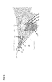
FIG. 4 is diagram of an operation of an obstacle data model construction system in accordance with embodiments; -
FIG. 5 is a graphical depiction of a LIDAR cone in accordance with embodiments; and -
FIG. 6 is a flow diagram of an operation of an obstacle data model construction system with range sensor shadows for use in motion planning in accordance with embodiments. - The detailed description explains embodiments of the invention, together with advantages and features, by way of example with reference to the drawings.
- As will be described below, a method of using "sensor shadows" as a way to estimate an extent of an obstacle in a vehicle obstacle space is provided.
- With reference to
FIGS. 1 and 2 , a vehicle such as a ground-based vehicle or anaircraft 1 is provided. In the case of the vehicle being anaircraft 1, theaircraft 1 includes anairframe 2, which may be formed to define a cabin that can accommodate a pilot and at least one or more crewmen or passengers and has anupper portion 3 and a tail portion 4. Amain rotor apparatus 5 is operably disposed at theupper portion 3 and atail rotor apparatus 6 is operably disposed at the tail portion 4. Themain rotor apparatus 5 may be provided as a single rotor or at coaxial counterrotating rotors. Thetail rotor apparatus 6 may be provided as a tail rotor or a propeller. In either case, operations of themain rotor apparatus 5 and thetail rotor apparatus 6 relative to theairframe 2 drive mission operations of theaircraft 1. - As shown in
FIG. 2 , theairframe 2 is further formed to encompass an engine 7, a transmission 8 and amission computer 9, which is operably coupled to themain rotor apparatus 5, thetail rotor apparatus 6, the engine 7 and the transmission 8. In accordance with commands issued by themission computer 9, the engine 7 drives the operations of themain rotor apparatus 5 and thetail rotor apparatus 6 via the transmission 8 for mission control and navigation purposes. Themission computer 9 additionally issues collective and cyclic servo commands to themain rotor apparatus 6 and thetail rotor apparatus 6 to provide for additional mission controls and navigation. - The
mission computer 9 includes amemory unit 90, aprocessor unit 91 and asensor system 92. Thesensor system 92 may be provided as a light detection and ranging (LIDAR) system or as another range sensing system and may be disposed at various points on theairframe 2 and senses various characteristics of a vehicle obstacle space surrounding theaircraft 1. Theprocessor unit 91 receives information from thesensor system 92 and analyzes that information in accordance with executable instructions stored on thememory unit 90. The information and analysis will be described in greater detail below. - Although illustrated in
FIGS. 1 and 2 as a piloted helicopter, it is to be understood that this is merely exemplary and that theaircraft 1 can be any type of ground- or air-based vehicle and can be manned, unmanned or remotely piloted. - With reference to
FIGS. 3-6 and, in accordance with an aspect, a method of operating an obstacle data model construction system of theaircraft 1 described above is provided. With a vehicle, such as theaircraft 1, moving through avehicle obstacle space 10 from afirst position 11 to asecond position 12 and then to third and fourthsequential positions vehicle obstacle space 10 at least at thefirst position 11 and the second positions 12 (operation 100). The method further includes generating at least first and second boundary data sets (seeboundary data 20 inFIG. 4 ) from results of the scanning at thefirst position 11 and thesecond position 12, respectively (operation 110), and deriving at least first and second shrouded regions (see shroudedregions 30 inFIGS. 4 and6 ) from the first and second boundary data sets, respectively (operation 120). - The generation of the first and second boundary data sets is made possible when the scanning shines light on an obstacle (see the obstacle rectangle in
FIGS. 4 and6 ) in thevehicle obstacle space 10. This obstacle reflects light back toward theaircraft 1 whereupon thesensor system 92 builds a data set that is representative of the reflective surface of the obstacle. This data set is used to then generate the boundary data sets ofoperation 110. Once the boundary data sets are generated, the deriving ofoperation 120 proceeds and includes assuming that anobstacle 60 exists behind boundaries, which may be manifested as grid lines generated on a graphical user interface or display. For the scanning at the first andsecond positions second positions - More particularly and with reference to
FIG. 5 , in a case where thesensor system 92 is provided as a LIDAR system, a LIDAR registered hit may occur at an inertial location (X, Y, Z) with range R and at an incident direction shown by inclination angles (λ, φ) and a maximum LIDAR detection range of R_max. In such a case, a LIDAR subcone may be defined with a registered point shown with a "tile" at range R of size RΔθ assuming a LIDAR beam dispersion of Δθ. This tile casts a shadow volume behind until the LIDAR range R_max. Given a series of scan points (within a single LIDAR scan), a series on non-intersecting shadow sub-cones can be generated and combined together to form a single shadow volume per scan. For each subsequent scan, a new shadow volume may be generated and intersected with the previous shadow region(s). The intersections would provide a volume of high-confidence that an obstacle exists. The union of shadow regions minus the intersections, would be regions of lower confidence and can be decayed in probability with time. - With the above in mind, intersections of subsequent shadow volumes C+ from a series of LIDAR scans provide for a shadow volume region that has a higher confidence of being occupied. Alternatively, the union of all sensor shadows minus C+, which is represented by C- below, can be included as a region where the confidence of occupancy is lower and may decay at an appropriate "forgetting" rate. Thus, the following is true.
- Cij is the ith sub-cone in the jth LIDAR scan.
Cj = UCij is shadow region, i.e. the union of all sub-cones in the jth LIDAR scan.
C + = ∩ Cj is the intersection of all shadow regions (which grows confidence)
C- =U Cj - ∩ Cj is the intersection of all shadow (which may decay in confidence) - In case the region is represented in the form of a grid, the grid cells that fall within the current sensor scanning range, but do not fall under the current sensor shadow volume, can be reduced in confidence by a higher "forgetting rate," such as ΔPdelete. The grid cells that do not fall within the current sensor scanning range, can be reduced in confidence by a lower "forgetting rate" ΔPforget. The grid cells that fall within the current sensor scanning range and fall under the C+ are incremented in confidence by ΔPincrease. Here, the "forgetting rate" is a decrement value in the probability of occupancy applied after each scan. A representation of the cell probability update can therefore be:

- Of course, P(cell i, scan k) is bound below by zero and bounded above by 1. So the update law works within these limits.
- In accordance with embodiments, in order to register a shadow region in a world model, the shadow region can be represented by a polytope (polygonal volume) or can be broken down into 3D grid cells and registered into a grid or octree data base. The grid approach may be easier to implement and intersect, update and recompute than the polygonal shape approach but requires more memory space than the polygonal shape approach. In accordance with further embodiments, LIDAR points that are closely registered can be attributed to a common line or surface and surface-identification algorithms can in real-time construct these surfaces based on streamed LIDAR data (see again
boundary data 20 inFIG. 4 ). These algorithms can reject outliers, fill gaps and construct a tight estimate of the surface. This tight surface estimate can result in a tighter estimate of the shadow region for a particular scan. - Subsequently, the method includes either identifying a high confidence occupancy region (see sequential high
confidence occupancy regions FIG. 6 with highest confidence occupancy region being region 43) from intersecting portions of the first and second shrouded regions (operation 130) or conservatively identifying an occupancy region (see occupancy region 50 inFIG. 6 ) from the union of the first and second shrouded regions (operation 140). - Especially in the case of the vehicle being the
aircraft 1 or some other type of helicopter or aircraft, the scanning ofoperation 100 may be performed by thesensor system 92. In such cases, thesensor system 92 may be disposed at a front and/or rear end of theairframe 2. The scanning ofoperation 100 may be performed as conical scanning operations of thevehicle obstacle space 10 in three dimensions, where a cone-shape of the conical scanning may be defined by a field of view of a LIDAR sensor. Conversely, where the vehicle is a ground based vehicle, such as a car, the scanning ofoperation 100 may be performed as cone-shaped scanning operations in two dimensions. - In accordance with embodiments, although the scanning of
operation 100 is described above with respect to the first andsecond positions operation 100 may be conducted or performed at multiple additional positions. In such cases, the generating, deriving and identifying operations relate to and use the results of the scanning performed at the first andsecond positions - In accordance with further embodiments, it will be understood that any obstacle associated with a high confidence occupancy region or an occupancy region in the
vehicle space 10 may be moving relative to theaircraft 1 or that theaircraft 1 is simply moving relative to the obstacle/occupancy region in thevehicle space 10. In such cases, the first and second shroudedregions 30 may be movable within thevehicle obstacle space 10 in accordance with the relative movement of the obstacle with respect to theaircraft 1, and the deriving ofoperation 120 includes introducing a time-based forgetting or decay factor into the computations used in the identifying ofoperations 130 and 140 (operation 121). This decay factor would modify the first and second boundary data sets and weigh earlier derived shrouded regions less than later derived shrouded regions in the identifying ofoperations - The obstacle data model construction system described above may be employed to adjust a mission plan of the
aircraft 1 during in- mission operations in order to avoid the highconfidence occupancy regions aircraft 1 and/or in that the adjustment can be based on a avoiding a singularly derived shrouded region 30 (seeFIG. 4 ) or a relatively low level high confidence region such ashigh confidence region 41 ofFIG. 6 . In any case, the adjustment of the mission plan may include construction of aroadmap 70 for theaircraft 1 that avoids the identifiedobstacle 60. - In accordance with further embodiments, the method may further include limiting additional scanning within a
high confidence region - For a particular mission instance for a vehicle, as shown in
FIG. 6 ,aircraft 1 may proceed throughvehicle obstacle space 10 and themission computer 9 will cause thesensor system 92 to begin scanning thevehicle obstacle space 10. In an event that obstacle 60 (i.e., a building) exists in thevehicle obstacle space 10, thesensor system 92 will shine on theobstacle 60 and the surface of theobstacle 60 will reflect light back toward theaircraft 1. This reflected light will be sensed by thesensor system 92 with the aircraft atposition 11 and theprocessing unit 91 will generate a boundary data set that is reflective of theobstacle 60 surface. Theprocessing unit 91 will then assume that an obstacle exists behind the boundary data set in deriving a shrouded region. As the aircraft proceeds throughpositions confidence occupancy regions - Once the
processing unit 91 identifies the shrouded regions and the highconfidence occupancy regions processing unit 91 will determine whether the mission plan of theaircraft 1 needs to be adjusted in order to avoid theobstacle 60. This determination may be executed conservatively to the extent possible to reduce the likelihood of an error. In addition, theprocessing unit 91 may limit additional scanning of the shrouded regions and the highconfidence occupancy regions - While the invention has been described in detail in connection with only a limited number of embodiments, it should be readily understood that the invention is not limited to such disclosed embodiments. Rather, the invention can be modified to incorporate any number of variations, alterations, substitutions or equivalent arrangements not heretofore described, but which are commensurate with the spirit and scope of the invention. Additionally, while various embodiments of the invention have been described, it is to be understood that aspects of the invention may include only some of the described embodiments. Accordingly, the invention is not to be seen as limited by the foregoing description, but is only limited by the scope of the appended claims.
Claims (10)
- A method of operating an obstacle data model construction system, comprising:with a vehicle (1) moving through a vehicle obstacle space (10), scanning (100) the vehicle obstacle space (10) at multiple positions;generating (110) boundary data sets (20) from results of the scanning at each of the multiple positions, respectively;deriving (120) shrouded regions (30) from the boundary data sets (20), respectively; andidentifying (130) a high confidence occupancy region from intersecting portions of the shrouded regions (30) and/or identifying an occupancy region from a union of the shrouded regions (30).
- The method according to claim 1, wherein the scanning (100) comprises conical scanning ahead of the vehicle (1), a cone-shape of the conical scanning being defined by a field of view of a light detection and ranging (LIDAR) sensor.
- The method according to either of claims 1 or 2, comprising:with the vehicle (1) moving through the vehicle obstacle space (10) from a first
position (11) to a second position (12), scanning the vehicle obstacle space (10) at the first and the second positions (11, 12);generating first and second boundary data sets (20) from results of the scanning at the
first and second positions (11, 12), respectively;deriving first and second shrouded regions (30) from the first and second boundary
data sets (20), respectively; andidentifying a high confidence occupancy region from intersecting portions of the first
and second shrouded regions (11, 12). - The method according to claim 3, wherein the scanning (100) is executed at the first and second positions (11, 12) and at additional positions (13, 14), wherein the deriving (120) and identifying (130) employ the results of the scanning (100) at the first and second positions (11, 12) and results of the scanning (100) at the additional positions (13, 14).
- The method according to any of claims 1-4, wherein the deriving (120) comprises assuming that an obstacle exists behind boundaries, which are respectively represented by the boundary data sets (20), relative to a location of the vehicle (1) at the multiple positions.
- The method according to any of claims 1-5, wherein the shrouded regions (30) are movable within the vehicle obstacle space (10) and the deriving (120) comprises introducing a decay factor modifying the boundary data sets (20).
- The method according to any of claims 1-6, further comprising adjusting a mission plan to avoid the high confidence occupancy region.
- The method according to claim 7, wherein the adjusting comprises constructing a roadmap (70) for the vehicle (1).
- The method according to claim any of claims 1-8, further comprising limiting additional scanning in the high confidence region.
- The method according to any of claims 1-9, wherein the vehicle (1) is an aircraft.
Applications Claiming Priority (1)
| Application Number | Priority Date | Filing Date | Title |
|---|---|---|---|
| US201462019607P | 2014-07-01 | 2014-07-01 |
Publications (1)
| Publication Number | Publication Date |
|---|---|
| EP2963446A1 true EP2963446A1 (en) | 2016-01-06 |
Family
ID=53510695
Family Applications (1)
| Application Number | Title | Priority Date | Filing Date |
|---|---|---|---|
| EP15174719.3A Withdrawn EP2963446A1 (en) | 2014-07-01 | 2015-07-01 | Obstacle data model construction system with range sensor shadows and use in motion planning |
Country Status (2)
| Country | Link |
|---|---|
| US (1) | US9798007B2 (en) |
| EP (1) | EP2963446A1 (en) |
Cited By (2)
| Publication number | Priority date | Publication date | Assignee | Title |
|---|---|---|---|---|
| CN108225323A (en) * | 2017-12-26 | 2018-06-29 | 中国人民解放军63920部队 | Determine to settle in an area method, medium and the equipment on boundary based on deviation effects directional combination |
| WO2023009907A1 (en) * | 2021-07-29 | 2023-02-02 | Qualcomm Incorporated | Occupancy mapping for autonomous control of a vehicle |
Families Citing this family (10)
| Publication number | Priority date | Publication date | Assignee | Title |
|---|---|---|---|---|
| DE102016122296A1 (en) * | 2016-11-21 | 2018-05-24 | Valeo Schalter Und Sensoren Gmbh | Method for detecting and classifying an object by means of at least one sensor device based on an occupancy map, driver assistance system and motor vehicle |
| US20180203100A1 (en) * | 2017-01-19 | 2018-07-19 | Honeywell International Inc. | Quality metric for ranging sensor in a degraded visual environment for a situational awareness system |
| US11487988B2 (en) * | 2017-08-31 | 2022-11-01 | Ford Global Technologies, Llc | Augmenting real sensor recordings with simulated sensor data |
| US11455565B2 (en) * | 2017-08-31 | 2022-09-27 | Ford Global Technologies, Llc | Augmenting real sensor recordings with simulated sensor data |
| CN108225328A (en) * | 2017-12-29 | 2018-06-29 | 北京领航视觉科技有限公司 | A kind of interior three dimensional data collection method |
| US10948578B2 (en) * | 2018-10-10 | 2021-03-16 | International Business Machines Corporation | Distinguishing holographic objects from physical objects |
| US10460581B1 (en) * | 2019-05-15 | 2019-10-29 | Cognitive Systems Corp. | Determining a confidence for a motion zone identified as a location of motion for motion detected by wireless signals |
| CN114114200B (en) * | 2021-03-23 | 2025-10-21 | 北京京东振世信息技术有限公司 | Data processing method and device |
| US20230113589A1 (en) * | 2021-10-08 | 2023-04-13 | Arizona Board Of Regents On Behalf Of Arizona State University | Biometeorological sensing device with embedded computer vision |
| WO2024070460A1 (en) * | 2022-09-30 | 2024-04-04 | 本田技研工業株式会社 | Mobile body control system, control method therefor, program, and mobile body |
Citations (1)
| Publication number | Priority date | Publication date | Assignee | Title |
|---|---|---|---|---|
| DE102007013023A1 (en) * | 2007-03-19 | 2008-09-25 | Ibeo Automobile Sensor Gmbh | Recursive method for providing raster card, involves assigning actual individual value to free lattice cell of single measuring raster, where actual individual value is based on distance from free lattice cell to ambient environment sensor |
Family Cites Families (12)
| Publication number | Priority date | Publication date | Assignee | Title |
|---|---|---|---|---|
| IL117792A (en) * | 1995-05-08 | 2003-10-31 | Rafael Armament Dev Authority | Autonomous command and control unit for mobile platform |
| US5831724A (en) * | 1997-07-22 | 1998-11-03 | The United States Of America As Represented By The Secretary Of The Navy | Imaging lidar-based aim verification method and system |
| KR100446635B1 (en) | 2001-11-27 | 2004-09-04 | 삼성전자주식회사 | Apparatus and method for depth image-based representation of 3-dimensional object |
| AU2006306523B2 (en) | 2005-10-21 | 2011-05-19 | Deere & Company | Systems and methods for switching between autonomous and manual operation of a vehicle |
| KR101321303B1 (en) | 2005-12-08 | 2013-10-25 | 어드밴스트 사이언티픽 컨셉츠 인크. | Laser ranging, tracking and designation using 3-d focal planes |
| US8050863B2 (en) | 2006-03-16 | 2011-11-01 | Gray & Company, Inc. | Navigation and control system for autonomous vehicles |
| US7974460B2 (en) | 2007-02-06 | 2011-07-05 | Honeywell International Inc. | Method and system for three-dimensional obstacle mapping for navigation of autonomous vehicles |
| AU2008229615B2 (en) | 2007-03-21 | 2012-05-17 | Commonwealth Scientific And Industrial Research Organisation | Method for planning and executing obstacle-free paths for rotating excavation machinery |
| US20100053593A1 (en) | 2008-08-26 | 2010-03-04 | Honeywell International Inc. | Apparatus, systems, and methods for rotating a lidar device to map objects in an environment in three dimensions |
| US8260539B2 (en) | 2010-05-12 | 2012-09-04 | GM Global Technology Operations LLC | Object and vehicle detection and tracking using 3-D laser rangefinder |
| US8918209B2 (en) | 2010-05-20 | 2014-12-23 | Irobot Corporation | Mobile human interface robot |
| US8958911B2 (en) | 2012-02-29 | 2015-02-17 | Irobot Corporation | Mobile robot |
-
2015
- 2015-06-30 US US14/755,784 patent/US9798007B2/en active Active
- 2015-07-01 EP EP15174719.3A patent/EP2963446A1/en not_active Withdrawn
Patent Citations (1)
| Publication number | Priority date | Publication date | Assignee | Title |
|---|---|---|---|---|
| DE102007013023A1 (en) * | 2007-03-19 | 2008-09-25 | Ibeo Automobile Sensor Gmbh | Recursive method for providing raster card, involves assigning actual individual value to free lattice cell of single measuring raster, where actual individual value is based on distance from free lattice cell to ambient environment sensor |
Non-Patent Citations (2)
| Title |
|---|
| BESL P J ET AL: "A METHOD FOR REGISTRATION OF 3-D SHAPES", IEEE TRANSACTIONS ON PATTERN ANALYSIS AND MACHINE INTELLIGENCE, IEEE COMPUTER SOCIETY, USA, vol. 14, no. 2, 1 February 1992 (1992-02-01), pages 239 - 256, XP000248481, ISSN: 0162-8828, DOI: 10.1109/34.121791 * |
| HOSEINNEZHAD R ET AL: "Sensor fusion for ultrasonic and laser arrays in mobile robotics: a comparative study of fuzzy, dempster and bayesian approaches", PROCEEDINGS OF IEEE SENSORS 2002. ORLANDO, FL, JUNE 12 - 14, 2002; [IEEE INTERNATIONAL CONFERENCE ON SENSORS], NEW YORK, NY : IEEE, US, vol. 2, 12 June 2002 (2002-06-12), pages 1682 - 1689, XP010605376, ISBN: 978-0-7803-7454-6, DOI: 10.1109/ICSENS.2002.1037377 * |
Cited By (4)
| Publication number | Priority date | Publication date | Assignee | Title |
|---|---|---|---|---|
| CN108225323A (en) * | 2017-12-26 | 2018-06-29 | 中国人民解放军63920部队 | Determine to settle in an area method, medium and the equipment on boundary based on deviation effects directional combination |
| CN108225323B (en) * | 2017-12-26 | 2021-04-06 | 中国人民解放军63920部队 | Method, medium, and apparatus for determining landing zone boundaries based on deviation influence direction combinations |
| WO2023009907A1 (en) * | 2021-07-29 | 2023-02-02 | Qualcomm Incorporated | Occupancy mapping for autonomous control of a vehicle |
| US12103540B2 (en) | 2021-07-29 | 2024-10-01 | Qualcomm Incorporated | Occupancy mapping for autonomous control of a vehicle |
Also Published As
| Publication number | Publication date |
|---|---|
| US9798007B2 (en) | 2017-10-24 |
| US20160216377A1 (en) | 2016-07-28 |
Similar Documents
| Publication | Publication Date | Title |
|---|---|---|
| US9798007B2 (en) | Obstacle data model construction system with range sensor shadows and use in motion planning | |
| US11898855B2 (en) | Assistance control system that prioritizes route candidates based on unsuitable sections thereof | |
| CN111366938B (en) | Method, device and vehicle for measuring trailer angle | |
| US10131446B1 (en) | Addressing multiple time around (MTA) ambiguities, particularly for lidar systems, and particularly for autonomous aircraft | |
| CN109141446B (en) | Method, apparatus, device and computer-readable storage medium for obtaining map | |
| EP3932763A1 (en) | Method and apparatus for generating route planning model, and device | |
| CN111201448B (en) | Methods and apparatus for generating inverse sensor models and methods for identifying obstacles | |
| US10571916B2 (en) | Control method for autonomous vehicles | |
| JP7611659B2 (en) | System and method for generating a flight path for navigating an aircraft - Patents.com | |
| EP3842836B1 (en) | Method, apparatus and storage medium for positioning object | |
| EP4052189A1 (en) | Training trajectory scoring neural networks to accurately assign scores | |
| WO2018221453A1 (en) | Output device, control method, program, and storage medium | |
| RU2764708C1 (en) | Methods and systems for processing lidar sensor data | |
| CN112183180A (en) | Method and apparatus for three-dimensional object bounding of two-dimensional image data | |
| EP3846074B1 (en) | Predicting future events in self driving cars | |
| CN112539943B (en) | Method and system for testing overtaking capability, test management center and storage medium | |
| CN115951713A (en) | How to control the drone | |
| US20170261996A1 (en) | Location and mapping device and method | |
| KR102137313B1 (en) | Method and system for controlling lidar sensor | |
| CN112256052A (en) | Speed control method, device, unmanned aerial vehicle and storage medium of unmanned aerial vehicle | |
| CN115597649A (en) | occupancy grid calibration | |
| CN120215558A (en) | A method, device and medium for controlling fixed-point landing of unmanned aerial vehicle | |
| Zimmermann et al. | Integration of a visibility graph based path planning method in the ACT/FHS rotorcraft | |
| CN120352884A (en) | Velocity correction in object pose determination | |
| US11774596B2 (en) | Streaming object detection within sensor data |
Legal Events
| Date | Code | Title | Description |
|---|---|---|---|
| PUAI | Public reference made under article 153(3) epc to a published international application that has entered the european phase |
Free format text: ORIGINAL CODE: 0009012 |
|
| AK | Designated contracting states |
Kind code of ref document: A1 Designated state(s): AL AT BE BG CH CY CZ DE DK EE ES FI FR GB GR HR HU IE IS IT LI LT LU LV MC MK MT NL NO PL PT RO RS SE SI SK SM TR |
|
| AX | Request for extension of the european patent |
Extension state: BA ME |
|
| 17P | Request for examination filed |
Effective date: 20160615 |
|
| RBV | Designated contracting states (corrected) |
Designated state(s): AL AT BE BG CH CY CZ DE DK EE ES FI FR GB GR HR HU IE IS IT LI LT LU LV MC MK MT NL NO PL PT RO RS SE SI SK SM TR |
|
| STAA | Information on the status of an ep patent application or granted ep patent |
Free format text: STATUS: EXAMINATION IS IN PROGRESS |
|
| 17Q | First examination report despatched |
Effective date: 20190509 |
|
| GRAP | Despatch of communication of intention to grant a patent |
Free format text: ORIGINAL CODE: EPIDOSNIGR1 |
|
| STAA | Information on the status of an ep patent application or granted ep patent |
Free format text: STATUS: GRANT OF PATENT IS INTENDED |
|
| INTG | Intention to grant announced |
Effective date: 20200728 |
|
| STAA | Information on the status of an ep patent application or granted ep patent |
Free format text: STATUS: THE APPLICATION IS DEEMED TO BE WITHDRAWN |
|
| 18D | Application deemed to be withdrawn |
Effective date: 20201208 |