EP2963141A1 - Suspension plasma spray apparatus and use methods - Google Patents
Suspension plasma spray apparatus and use methods Download PDFInfo
- Publication number
- EP2963141A1 EP2963141A1 EP15171676.8A EP15171676A EP2963141A1 EP 2963141 A1 EP2963141 A1 EP 2963141A1 EP 15171676 A EP15171676 A EP 15171676A EP 2963141 A1 EP2963141 A1 EP 2963141A1
- Authority
- EP
- European Patent Office
- Prior art keywords
- suspension
- vibrator
- line
- plasma spray
- supply line
- Prior art date
- Legal status (The legal status is an assumption and is not a legal conclusion. Google has not performed a legal analysis and makes no representation as to the accuracy of the status listed.)
- Granted
Links
Images
Classifications
-
- B—PERFORMING OPERATIONS; TRANSPORTING
- B01—PHYSICAL OR CHEMICAL PROCESSES OR APPARATUS IN GENERAL
- B01F—MIXING, e.g. DISSOLVING, EMULSIFYING OR DISPERSING
- B01F23/00—Mixing according to the phases to be mixed, e.g. dispersing or emulsifying
- B01F23/50—Mixing liquids with solids
- B01F23/55—Mixing liquids with solids the mixture being submitted to electrical, sonic or similar energy
- B01F23/551—Mixing liquids with solids the mixture being submitted to electrical, sonic or similar energy using vibrations
-
- B—PERFORMING OPERATIONS; TRANSPORTING
- B05—SPRAYING OR ATOMISING IN GENERAL; APPLYING FLUENT MATERIALS TO SURFACES, IN GENERAL
- B05B—SPRAYING APPARATUS; ATOMISING APPARATUS; NOZZLES
- B05B7/00—Spraying apparatus for discharge of liquids or other fluent materials from two or more sources, e.g. of liquid and air, of powder and gas
- B05B7/16—Spraying apparatus for discharge of liquids or other fluent materials from two or more sources, e.g. of liquid and air, of powder and gas incorporating means for heating or cooling the material to be sprayed
- B05B7/22—Spraying apparatus for discharge of liquids or other fluent materials from two or more sources, e.g. of liquid and air, of powder and gas incorporating means for heating or cooling the material to be sprayed electrically, magnetically or electromagnetically, e.g. by arc
- B05B7/222—Spraying apparatus for discharge of liquids or other fluent materials from two or more sources, e.g. of liquid and air, of powder and gas incorporating means for heating or cooling the material to be sprayed electrically, magnetically or electromagnetically, e.g. by arc using an arc
-
- B—PERFORMING OPERATIONS; TRANSPORTING
- B01—PHYSICAL OR CHEMICAL PROCESSES OR APPARATUS IN GENERAL
- B01D—SEPARATION
- B01D3/00—Distillation or related exchange processes in which liquids are contacted with gaseous media, e.g. stripping
- B01D3/006—Distillation or related exchange processes in which liquids are contacted with gaseous media, e.g. stripping by vibration
-
- B—PERFORMING OPERATIONS; TRANSPORTING
- B01—PHYSICAL OR CHEMICAL PROCESSES OR APPARATUS IN GENERAL
- B01F—MIXING, e.g. DISSOLVING, EMULSIFYING OR DISPERSING
- B01F31/00—Mixers with shaking, oscillating, or vibrating mechanisms
- B01F31/60—Mixers with shaking, oscillating, or vibrating mechanisms with a vibrating receptacle
-
- B—PERFORMING OPERATIONS; TRANSPORTING
- B05—SPRAYING OR ATOMISING IN GENERAL; APPLYING FLUENT MATERIALS TO SURFACES, IN GENERAL
- B05B—SPRAYING APPARATUS; ATOMISING APPARATUS; NOZZLES
- B05B7/00—Spraying apparatus for discharge of liquids or other fluent materials from two or more sources, e.g. of liquid and air, of powder and gas
- B05B7/14—Spraying apparatus for discharge of liquids or other fluent materials from two or more sources, e.g. of liquid and air, of powder and gas designed for spraying particulate materials
- B05B7/1404—Arrangements for supplying particulate material
- B05B7/144—Arrangements for supplying particulate material the means for supplying particulate material comprising moving mechanical means
- B05B7/1445—Arrangements for supplying particulate material the means for supplying particulate material comprising moving mechanical means involving vibrations
-
- B—PERFORMING OPERATIONS; TRANSPORTING
- B05—SPRAYING OR ATOMISING IN GENERAL; APPLYING FLUENT MATERIALS TO SURFACES, IN GENERAL
- B05B—SPRAYING APPARATUS; ATOMISING APPARATUS; NOZZLES
- B05B7/00—Spraying apparatus for discharge of liquids or other fluent materials from two or more sources, e.g. of liquid and air, of powder and gas
- B05B7/16—Spraying apparatus for discharge of liquids or other fluent materials from two or more sources, e.g. of liquid and air, of powder and gas incorporating means for heating or cooling the material to be sprayed
- B05B7/22—Spraying apparatus for discharge of liquids or other fluent materials from two or more sources, e.g. of liquid and air, of powder and gas incorporating means for heating or cooling the material to be sprayed electrically, magnetically or electromagnetically, e.g. by arc
- B05B7/222—Spraying apparatus for discharge of liquids or other fluent materials from two or more sources, e.g. of liquid and air, of powder and gas incorporating means for heating or cooling the material to be sprayed electrically, magnetically or electromagnetically, e.g. by arc using an arc
- B05B7/226—Spraying apparatus for discharge of liquids or other fluent materials from two or more sources, e.g. of liquid and air, of powder and gas incorporating means for heating or cooling the material to be sprayed electrically, magnetically or electromagnetically, e.g. by arc using an arc the material being originally a particulate material
-
- C—CHEMISTRY; METALLURGY
- C23—COATING METALLIC MATERIAL; COATING MATERIAL WITH METALLIC MATERIAL; CHEMICAL SURFACE TREATMENT; DIFFUSION TREATMENT OF METALLIC MATERIAL; COATING BY VACUUM EVAPORATION, BY SPUTTERING, BY ION IMPLANTATION OR BY CHEMICAL VAPOUR DEPOSITION, IN GENERAL; INHIBITING CORROSION OF METALLIC MATERIAL OR INCRUSTATION IN GENERAL
- C23C—COATING METALLIC MATERIAL; COATING MATERIAL WITH METALLIC MATERIAL; SURFACE TREATMENT OF METALLIC MATERIAL BY DIFFUSION INTO THE SURFACE, BY CHEMICAL CONVERSION OR SUBSTITUTION; COATING BY VACUUM EVAPORATION, BY SPUTTERING, BY ION IMPLANTATION OR BY CHEMICAL VAPOUR DEPOSITION, IN GENERAL
- C23C4/00—Coating by spraying the coating material in the molten state, e.g. by flame, plasma or electric discharge
- C23C4/04—Coating by spraying the coating material in the molten state, e.g. by flame, plasma or electric discharge characterised by the coating material
- C23C4/10—Oxides, borides, carbides, nitrides or silicides; Mixtures thereof
-
- C—CHEMISTRY; METALLURGY
- C23—COATING METALLIC MATERIAL; COATING MATERIAL WITH METALLIC MATERIAL; CHEMICAL SURFACE TREATMENT; DIFFUSION TREATMENT OF METALLIC MATERIAL; COATING BY VACUUM EVAPORATION, BY SPUTTERING, BY ION IMPLANTATION OR BY CHEMICAL VAPOUR DEPOSITION, IN GENERAL; INHIBITING CORROSION OF METALLIC MATERIAL OR INCRUSTATION IN GENERAL
- C23C—COATING METALLIC MATERIAL; COATING MATERIAL WITH METALLIC MATERIAL; SURFACE TREATMENT OF METALLIC MATERIAL BY DIFFUSION INTO THE SURFACE, BY CHEMICAL CONVERSION OR SUBSTITUTION; COATING BY VACUUM EVAPORATION, BY SPUTTERING, BY ION IMPLANTATION OR BY CHEMICAL VAPOUR DEPOSITION, IN GENERAL
- C23C4/00—Coating by spraying the coating material in the molten state, e.g. by flame, plasma or electric discharge
- C23C4/12—Coating by spraying the coating material in the molten state, e.g. by flame, plasma or electric discharge characterised by the method of spraying
- C23C4/134—Plasma spraying
-
- H—ELECTRICITY
- H05—ELECTRIC TECHNIQUES NOT OTHERWISE PROVIDED FOR
- H05H—PLASMA TECHNIQUE; PRODUCTION OF ACCELERATED ELECTRICALLY-CHARGED PARTICLES OR OF NEUTRONS; PRODUCTION OR ACCELERATION OF NEUTRAL MOLECULAR OR ATOMIC BEAMS
- H05H1/00—Generating plasma; Handling plasma
- H05H1/24—Generating plasma
- H05H1/26—Plasma torches
- H05H1/32—Plasma torches using an arc
- H05H1/42—Plasma torches using an arc with provisions for introducing materials into the plasma, e.g. powder or liquid
-
- Y—GENERAL TAGGING OF NEW TECHNOLOGICAL DEVELOPMENTS; GENERAL TAGGING OF CROSS-SECTIONAL TECHNOLOGIES SPANNING OVER SEVERAL SECTIONS OF THE IPC; TECHNICAL SUBJECTS COVERED BY FORMER USPC CROSS-REFERENCE ART COLLECTIONS [XRACs] AND DIGESTS
- Y10—TECHNICAL SUBJECTS COVERED BY FORMER USPC
- Y10T—TECHNICAL SUBJECTS COVERED BY FORMER US CLASSIFICATION
- Y10T29/00—Metal working
- Y10T29/49—Method of mechanical manufacture
- Y10T29/49826—Assembling or joining
- Y10T29/49828—Progressively advancing of work assembly station or assembled portion of work
Definitions
- the disclosure relates to suspension plasma spray. More particularly, the disclosure relates to suspension plasma spray feeder apparatus.
- Suspension plasma spray is a form of plasma spray wherein a particulate suspended in a carrier liquid is delivered to the plasma spray gun. This may be distinguished, for example, from other systems wherein powder is fed directly into the gun to interact with plasma and any residual carrier gas or from non-powder systems (e.g., wire systems). Suspension plasma spray systems present issues of clogging not relevant to other spray systems. It has been known to use an orifice in the flowpath to control out feed rate and pressure of the output. Filters may be employed to prohibit large agglomerates or particles from building up in the flow path or reaching an orifice.
- a recirculating flowpath is used to prevent clogging when the gun is not spraying.
- a valve is provided in a suspension supply line somewhere between a suspension source and the gun. The valve may shut off suspension flow to the gun.
- a return line/flowpath is provided branching from the supply line/flowpath to the source just upstream of the valve. This return flowpath may have its own valve or, equivalently, the first valve may be a three-way valve.
- the branch flowpath may contain an orifice for providing a sufficient pressure restriction to limit the flow rate of the recirculating flow.
- the feeder apparatus comprises a suspension line and a vibrator mounted to vibrate the suspension line.
- a further embodiment may additionally and/or alternatively include the suspension line being either: a suspension supply line for passing suspension from the suspension source to the plasma spray gun; or if present, a suspension recirculation line coupled to the suspension supply line to return suspension to the suspension source.
- the suspension line being either: a suspension supply line for passing suspension from the suspension source to the plasma spray gun; or if present, a suspension recirculation line coupled to the suspension supply line to return suspension to the suspension source.
- a further embodiment may additionally and/or alternatively include: the vibrator being a first vibrator mounted to vibrate the suspension supply line; the apparatus including the suspension recirculation line; and a second vibrator being mounted to vibrate the suspension recirculation line.
- a further embodiment may additionally and/or alternatively include a purge fluid supply line being coupled to the suspension line and the vibrator being downstream of a junction of the purge fluid supply line.
- a further embodiment may additionally and/or alternatively include the purge fluid supply line comprising a purge liquid supply line and a purge gas supply line.
- a further embodiment may additionally and/or alternatively include the vibrator being an air vibrator.
- a further embodiment may additionally and/or alternatively include the vibrator being a turbine vibrator.
- a further embodiment may additionally and/or alternatively include the suspension line comprising a metallic member and the vibrator being clamped to the metallic member.
- a further embodiment may additionally and/or alternatively include the vibrator being on or adjacent a filter housing or an orifice housing.
- a further embodiment may additionally and/or alternatively include the vibrator being within 20cm of a filter housing or an orifice housing.
- a further embodiment may additionally and/or alternatively include a suspension plasma spray apparatus including the suspension plasma spray feeder apparatus.
- a plasma spray gun is coupled to the suspension line or adjacent an outlet of the suspension line.
- a further embodiment may additionally and/or alternatively include a suspension supply coupled to the suspension supply line.
- a further embodiment may additionally and/or alternatively include the suspension supply comprising ceramic particulate in an alcohol-based carrier.
- a further embodiment may additionally and/or alternatively include a carrier gas supply coupled to the plasma spray gun.
- a further embodiment may additionally and/or alternatively include a power line coupled to the plasma spray gun.
- a further embodiment may additionally and/or alternatively include a method for manufacturing the suspension plasma spray feeder apparatus.
- the method comprises clamping the vibrator to the suspension line.
- a further embodiment may additionally and/or alternatively include connecting the vibrator to an air supply.
- a further embodiment may additionally and/or alternatively include the clamping being to or adjacent a filter housing or an orifice housing.
- a further embodiment may additionally and/or alternatively include a method for using the suspension plasma spray feeder apparatus.
- the method comprises: detecting a pressure parameter; and responsive to the detected pressure parameter, running the vibrator.
- a further embodiment may additionally and/or alternatively include: the suspension line being a suspension supply line; the vibrator being a first vibrator mounted to vibrate the suspension supply line; a suspension recirculation line branching from the suspension supply line; and a second vibrator being mounted to vibrate the suspension recirculation line.
- a further embodiment may additionally and/or alternatively include the running of the vibrator comprising delivering compressed air to the vibrator.
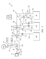
- FIG. 1 shows a suspension plasma spray system (SPS) 20 for applying a coating 22 to a workpiece 24.
- the exemplary workpiece 24 is a gas turbine engine component such as a blade, vane, combustor panel, outer air seal, or the like.
- An exemplary workpiece includes a metallic substrate which may be formed of an exemplary alloy such as a nickel-based superalloy. The substrate may bear one or more additional coating layers which may have been applied by SPS or other techniques (e.g., bond coats and the like).
- Exemplary coatings are ceramic coatings.
- Exemplary ceramic coatings are zirconia-based coatings such as yttria-stabilized zirconia (YSZ) and gadolinia-stabilized zirconia (GSZ).
- Exemplary coatings are discharged as a spray 28 carried by plasma discharge from an outlet 30 of a plasma gun 32.
- the system 20 includes a suspension source 34.
- the exemplary source 34 may contain a reservoir of a mixture of coating particles and a liquid carrier suspending the particles. Other variations may involve mixing the particles and the carrier at the source.
- the suspension source 34 may include items such as: one or more pumps and/or gas sources (e.g., air, Ar, and/or N 2 ) for pressurizing the suspension to drive suspension flow from the suspension source to the gun; meters; sensors; valves; diagnostic hardware; and the like.
- exemplary particles are of a ceramic such as a zirconia-based ceramic (e.g., at least 50% zirconia by weight).
- Exemplary liquid carrier is alcohol-based (e.g., at least 50% alcohol by weight).
- a flowpath (suspension supply flowpath) 36 extends from an outlet 38 of the suspension source 34 to a suspension 42 outlet.
- the exemplary outlet is external to the gun suspension outlet so that a suspension flow along the flowpath 36 may mix with carrier gas and/or associated plasma to be propelled as the spray 28.
- FIG. 1 shows plural gas sources 50-1 to 50-N of gases such as argon, helium, nitrogen, hydrogen, and the like as may be appropriate for the desired chemistry and physics of the particular gun and spray. These may have associated gas lines 52 and associated flowpaths extending to a mixer 54 which may include appropriate valves and the like for mixing in desired proportions.
- a line 56 extends from the mixer to the gun.
- FIG. 1 further shows a power source 60 coupled to the gun by wiring 62 to provide energy for generating the plasma.
- Alternative guns may integrate the suspension line into the gun body such that the mixing of the suspension with the plasma and carrier gas is internal to the gun (e.g., via internal outlets of each) with the mixture then leaving an overall outlet of the gun.
- FIG. 1 further shows a suspension supply line 70 extending along the flowpath 36 from the suspension source outlet 38 to the gun inlet 42.
- One or more valves 82 may be located along the suspension supply line and used as discussed below.
- a metering orifice 180 could be placed at or near the outlet 42.
- One or more filters may be located along the flowpath 36 to prevent agglomerates/large particles from plugging the orifice or building up in undesirable locations.
- proximate the orifice and/or the filter one may locate a vibrator to reduce any plugging buildup.
- the exemplary system 20 adds a recirculation flowpath (return flowpath) 84 comprising a suspension recirculation line (return line) 86 extending from a junction 88 with the supply flowpath 36 to an inlet or return port 90 of the suspension source 34.
- An exemplary valve 82 is a three-way for controlling flow along the return flowpath 84 in addition to flow along the supply flowpath.
- Recirculation by directing a return flow along the flowpath 84 may be used to prevent stagnation of the suspension and associated clogging.
- the use of a vibrator along the line 70/flowpath 36 may reduce the need for and advantages of such recirculation by preventing settling of suspended particulate in the line 70/flowpath 36.
- the flowpath 84 is used only when the gun is not in operation.
- the valve 82 may be closed/shut. This closing/shutting may be in addition to closing/shutting of a valve (not shown) at the gun.
- the gun valve may be closed only for relatively short durations during a spray process while the valve 82 may shut the supply flowpath for longer durations of gun non-use. With the valve 82 shutting/closing the supply flowpath, it is desired to prevent stagnation in the portion of the suspension supply flowpath 36 extending between the suspension source outlet 38 and the valve 82.
- valve 82 This may be achieved by configuring the valve 82 to enable a return flow along the flowpath 84. The result is that suspension will continue to recirculate in a loop 94 and will tend not to become stagnant and thus not clog the line 70.
- the valve 82 (which might be replaced by multiple valves) is configured to provide at least two conditions: a gun-off condition wherein flow recirculates along the loop 94 but flow from upstream to downstream of the valve along the supply flowpath 36 is blocked; and a gun-on condition wherein flow from upstream to downstream along the supply flowpath is permitted. In various implementations, this latter condition may or may not include flow through the recirculation line.
- the exemplary embodiment also provides a flush action for flushing the line 70 downstream of the valve 82.
- a purge fluid comprises sequential introduction of a purge liquid (e.g., water or water-based solution) for cleaning and a purge gas (e.g., air) for drying.
- FIG. 1 further shows a water supply 100 and an air supply 102.
- the supplies 100 ad 102 may be portions of or otherwise incorporate existing factory deionized water and compressed air systems but may include the addition of appropriate valving, sensors, and the like.
- FIG. 1 further shows water and air lines 104 and 106 merging and joining the flowpath 36 and line 70 at a junction 110.
- the exemplary junction 110 is just downstream of the valve 82.
- Valves 112 and 114 are shown for controlling respective flows of water and.air.
- key plugging points include the filter(s) and orifice(s).
- Filters can be anywhere along the flowpath 36. Exemplary locations are just after the reservoir and before any restrictions (e.g., the orifice) as this captures the large particles and prevents them from plugging the whole flow path. Orifice are used to meter flow on and flowpath.
- One exemplary orifice 180 is along the flowpath 36 (e.g., at near the outlet 42 and possibly internal to the gun if mixing occurs in the gun).
- Another exemplary orifice 222 is somewhere along the recirculation flowpath. Screens 230, 220 are slso shown in the supply and recirculation lines.
- These means include one or more vibrators 120, 122.
- one of the vibrators 122 is along the loop 94 while the other 120 is along the flowpath 36 downstream of the valve 82 (i.e., outside the loop 94).
- the vibrator 122 along the loop 94 is along the return flowpath 84 and line 86.
- the exemplary vibrator is an air vibrator.
- An exemplary air vibrator is an air turbine vibrator.
- An exemplary air turbine vibrator is the CVT-P-10 of Cleveland Vibrator Company of Cleveland, Ohio.
- Air vibrators may, thus, be connected to the same air supply 102 as is used to supply air to other components.
- FIG. 1 shows respective air supply lines 140 and 142 for the two vibrators each with a control valve 144, 146.
- Each of the exemplary vibrators has an inlet 150 coupled to the associated line 140, 142 and an outlet 152.
- the outlet 152 is exposed to the factory environment and, when the vibrator is operational, discharges an outlet air stream 154.
- FIG. 1 shows an exemplary pressure sensor 160 relatively upstream along the suspension supply line and flowpath.
- a partial blockage downstream of the sensor may cause an increase in pressure measured by the sensor. Responsive to this sensed increase, the vibrators could be actuated. Both vibrators may be simultaneously actuated or, depending upon the operational situation only one may be actuated even in situations where there are two or more vibrators.
- Yet other implementations involve pressure sensors wherein a pressure drop at the sensor indicates a blockage upstream of the sensor and, thereby, triggers vibration to clear lines of partial blockage.
- FIG. 1 further shows a controller 400.
- the controller may receive user inputs from an input device (e.g., switches, keyboard, or the like) and sensors (not shown, e.g., pressure sensors, flow meters, temperature sensors, and the like at various system locations).
- the controller may be coupled to the sensors and controllable system components (e.g., valves, pumps, and the like) via control lines (e.g., hardwired or wireless communication paths).
- the controller may include one or more: processors; memory (e.g., for storing program information for execution by the processor to perform the operational methods and for storing data used or generated by the program(s)); and hardware interface devices (e.g., ports) for interfacing with input/output devices and controllable system components.
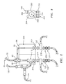
- FIG. 2 shows further details of an exemplary feeder system (subsystem) within the suspension plasma spray system 20 of FIG. 1 .
- Components are held by a bracket or housing structure (support) 200 and the exemplary orientation is illustrated as would be present in the factory with the flowpath 36 and line 70 approaching from above and departing below.
- a housing of the exemplary valve 82 provides the junction 88.
- the exemplary valve housing may be rigidly mounted to the support 200.
- the associated lines may include respective bulkhead unions 210, 212 engaging the support 200.
- Metallic tube extensions 214, 216 may rigidly depend from the unions and provide a robust line segment for which to mate the associated vibrator.
- an inline screen or filter assembly 220 is immediately downstream of the tube 216 and an orifice assembly 222 is immediately downstream of the screen assembly 220.
- the orifice and screen are particularly susceptible to clogging. Accordingly, this implementation provides vibration advantageously close to the potential clog location. Also, this configuration using metallic fittings along this location helps translate that vibration.
- Other line portions e.g., downstream of the orifice assembly 222 and upstream of the bulkhead union 212) may more appropriately be flexible polymeric tubing allowing easy routing and movement.
- the vibrator 120 is proximate a screen assembly 230.
- the proximity may mean on the housing of the screen/filter or orifice or appropriately adjacent thereto.
- polymeric tubing instead of exemplary metal (e.g., stainless steel)
- clamping of the vibrator to the polymeric tubing may have a closer desired proximity than with metal tubing.
- Exemplary proximity places the vibrator housing within 20cm (more narrowly 10cm or 5cm) of the housing of the screen/filter or orifice and within 25cm (more narrowly 12cm or 8cm) of the actual screen/filter media or orifice aperture. Nevertheless, more remote vibrator locations may still have a general benefit.
- the vibrator is upstream of the associated screen/filter or orifice. This has some benefit of helping break up agglomerations prior to reaching the element and being closer to the upstream side of the element where plugging is likely to develop.
- downstream locations are also possible, particularly in retrofit situations if space is more available downstream.
- FIG. 3 shows further details of the exemplary vibrator.
- the vibrator includes a main body 300 with the inlet 150 being formed along an inlet fitting 302 to the body.
- the outlet 152 is formed along a muffler 304 attached to the body.
- the body contains a turbine schematically shown as 300.
- a clamp 310 is matable to the body (e.g., via fasteners such as cap screws 312).
- the clamp and body define a space for capturing the associated line (e.g., a groove 314 in the body facing the clamp). Accordingly, in assembly (original manufacture or retrofit) a technician may place the clamp body adjacent the line with the groove 314 partially receiving the associated segment of line.
- the clamp 310 may be put in place and the cap screws inserted and tightened to securely mount the vibrator to the associated line.
- first, second, and the like in the following claims is for differentiation within the claim only and does not necessarily indicate relative or absolute importance or temporal order. Similarly, the identification in a claim of one element as “first” (or the like) does not preclude such "first” element from identifying an element that is referred to as “second” (or the like) in another claim or in the description.
Landscapes
- Chemical & Material Sciences (AREA)
- Engineering & Computer Science (AREA)
- Physics & Mathematics (AREA)
- Plasma & Fusion (AREA)
- Chemical Kinetics & Catalysis (AREA)
- Mechanical Engineering (AREA)
- Materials Engineering (AREA)
- Metallurgy (AREA)
- Organic Chemistry (AREA)
- Electromagnetism (AREA)
- Spectroscopy & Molecular Physics (AREA)
- Dispersion Chemistry (AREA)
- Nozzles (AREA)
Abstract
Description
- The disclosure relates to suspension plasma spray. More particularly, the disclosure relates to suspension plasma spray feeder apparatus.
- Suspension plasma spray (SPS) is a form of plasma spray wherein a particulate suspended in a carrier liquid is delivered to the plasma spray gun. This may be distinguished, for example, from other systems wherein powder is fed directly into the gun to interact with plasma and any residual carrier gas or from non-powder systems (e.g., wire systems). Suspension plasma spray systems present issues of clogging not relevant to other spray systems. It has been known to use an orifice in the flowpath to control out feed rate and pressure of the output. Filters may be employed to prohibit large agglomerates or particles from building up in the flow path or reaching an orifice.
- In some examples, a recirculating flowpath is used to prevent clogging when the gun is not spraying. For example, a valve is provided in a suspension supply line somewhere between a suspension source and the gun. The valve may shut off suspension flow to the gun. To prevent blockage upstream of the valve, a return line/flowpath is provided branching from the supply line/flowpath to the source just upstream of the valve. This return flowpath may have its own valve or, equivalently, the first valve may be a three-way valve. Thus, when the flow to the gun is shut off, flow along the branch flowpath is opened and flow can recirculate to avoid clogging. The branch flowpath may contain an orifice for providing a sufficient pressure restriction to limit the flow rate of the recirculating flow.
- One aspect of the disclosure involves a suspension plasma spray feeder apparatus for delivering a suspension from a suspension source to a plasma spray gun. The feeder apparatus comprises a suspension line and a vibrator mounted to vibrate the suspension line.
- A further embodiment may additionally and/or alternatively include the suspension line being either: a suspension supply line for passing suspension from the suspension source to the plasma spray gun; or if present, a suspension recirculation line coupled to the suspension supply line to return suspension to the suspension source.
- A further embodiment may additionally and/or alternatively include: the vibrator being a first vibrator mounted to vibrate the suspension supply line; the apparatus including the suspension recirculation line; and a second vibrator being mounted to vibrate the suspension recirculation line.
- A further embodiment may additionally and/or alternatively include a purge fluid supply line being coupled to the suspension line and the vibrator being downstream of a junction of the purge fluid supply line.
- A further embodiment may additionally and/or alternatively include the purge fluid supply line comprising a purge liquid supply line and a purge gas supply line.
- A further embodiment may additionally and/or alternatively include the vibrator being an air vibrator.
- A further embodiment may additionally and/or alternatively include the vibrator being a turbine vibrator.
- A further embodiment may additionally and/or alternatively include the suspension line comprising a metallic member and the vibrator being clamped to the metallic member.
- A further embodiment may additionally and/or alternatively include the vibrator being on or adjacent a filter housing or an orifice housing.
- A further embodiment may additionally and/or alternatively include the vibrator being within 20cm of a filter housing or an orifice housing.
- A further embodiment may additionally and/or alternatively include a suspension plasma spray apparatus including the suspension plasma spray feeder apparatus. A plasma spray gun is coupled to the suspension line or adjacent an outlet of the suspension line.
- A further embodiment may additionally and/or alternatively include a suspension supply coupled to the suspension supply line.
- A further embodiment may additionally and/or alternatively include the suspension supply comprising ceramic particulate in an alcohol-based carrier.
- A further embodiment may additionally and/or alternatively include a carrier gas supply coupled to the plasma spray gun.
- A further embodiment may additionally and/or alternatively include a power line coupled to the plasma spray gun.
- A further embodiment may additionally and/or alternatively include a method for manufacturing the suspension plasma spray feeder apparatus. The method comprises clamping the vibrator to the suspension line.
- A further embodiment may additionally and/or alternatively include connecting the vibrator to an air supply.
- A further embodiment may additionally and/or alternatively include the clamping being to or adjacent a filter housing or an orifice housing.
- A further embodiment may additionally and/or alternatively include a method for using the suspension plasma spray feeder apparatus. The method comprises: detecting a pressure parameter; and responsive to the detected pressure parameter, running the vibrator.
- A further embodiment may additionally and/or alternatively include: the suspension line being a suspension supply line; the vibrator being a first vibrator mounted to vibrate the suspension supply line; a suspension recirculation line branching from the suspension supply line; and a second vibrator being mounted to vibrate the suspension recirculation line.
- A further embodiment may additionally and/or alternatively include the running of the vibrator comprising delivering compressed air to the vibrator.
- The details of one or more embodiments are set forth in the accompanying drawings and the description below. Other features, objects, and advantages will be apparent from the description and drawings, and from the claims.
-
-
FIG. 1 is a schematic view of a suspension plasma spray apparatus. -
FIG. 2 is a view of a feeder of the apparatus ofFIG. 1 . -
FIG. 3 is a view of a vibrator for use with the feeder ofFIG. 2 . - Like reference numbers and designations in the various drawings indicate like elements.
-
FIG. 1 shows a suspension plasma spray system (SPS) 20 for applying acoating 22 to aworkpiece 24. Theexemplary workpiece 24 is a gas turbine engine component such as a blade, vane, combustor panel, outer air seal, or the like. An exemplary workpiece includes a metallic substrate which may be formed of an exemplary alloy such as a nickel-based superalloy. The substrate may bear one or more additional coating layers which may have been applied by SPS or other techniques (e.g., bond coats and the like). Exemplary coatings are ceramic coatings. Exemplary ceramic coatings are zirconia-based coatings such as yttria-stabilized zirconia (YSZ) and gadolinia-stabilized zirconia (GSZ). Exemplary coatings are discharged as aspray 28 carried by plasma discharge from anoutlet 30 of aplasma gun 32. - The
system 20 includes asuspension source 34. Theexemplary source 34 may contain a reservoir of a mixture of coating particles and a liquid carrier suspending the particles. Other variations may involve mixing the particles and the carrier at the source. Thesuspension source 34 may include items such as: one or more pumps and/or gas sources (e.g., air, Ar, and/or N2) for pressurizing the suspension to drive suspension flow from the suspension source to the gun; meters; sensors; valves; diagnostic hardware; and the like. As noted above, exemplary particles are of a ceramic such as a zirconia-based ceramic (e.g., at least 50% zirconia by weight). Exemplary liquid carrier is alcohol-based (e.g., at least 50% alcohol by weight). - A flowpath (suspension supply flowpath) 36 extends from an
outlet 38 of thesuspension source 34 to asuspension 42 outlet. The exemplary outlet is external to the gun suspension outlet so that a suspension flow along theflowpath 36 may mix with carrier gas and/or associated plasma to be propelled as thespray 28.FIG. 1 shows plural gas sources 50-1 to 50-N of gases such as argon, helium, nitrogen, hydrogen, and the like as may be appropriate for the desired chemistry and physics of the particular gun and spray. These may have associatedgas lines 52 and associated flowpaths extending to amixer 54 which may include appropriate valves and the like for mixing in desired proportions. Aline 56 extends from the mixer to the gun.FIG. 1 further shows apower source 60 coupled to the gun by wiring 62 to provide energy for generating the plasma. - Alternative guns may integrate the suspension line into the gun body such that the mixing of the suspension with the plasma and carrier gas is internal to the gun (e.g., via internal outlets of each) with the mixture then leaving an overall outlet of the gun.
-
FIG. 1 further shows asuspension supply line 70 extending along the flowpath 36 from thesuspension source outlet 38 to thegun inlet 42. One ormore valves 82 may be located along the suspension supply line and used as discussed below. - This represents a basic system for performing SPS. As with prior art systems, a
metering orifice 180 could be placed at or near theoutlet 42. One or more filters may be located along theflowpath 36 to prevent agglomerates/large particles from plugging the orifice or building up in undesirable locations. As is discussed further below, proximate the orifice and/or the filter one may locate a vibrator to reduce any plugging buildup. - As an optional variation, the
exemplary system 20 adds a recirculation flowpath (return flowpath) 84 comprising a suspension recirculation line (return line) 86 extending from ajunction 88 with thesupply flowpath 36 to an inlet or returnport 90 of thesuspension source 34. Anexemplary valve 82 is a three-way for controlling flow along thereturn flowpath 84 in addition to flow along the supply flowpath. - Recirculation by directing a return flow along the
flowpath 84 may be used to prevent stagnation of the suspension and associated clogging. However, the use of a vibrator along theline 70/flowpath 36 may reduce the need for and advantages of such recirculation by preventing settling of suspended particulate in theline 70/flowpath 36. - In one example where recirculation is present, the
flowpath 84 is used only when the gun is not in operation. In this example, when the gun is in operation, flow proceeds from thesuspension source outlet 38 along theflowpath 36 to and through the gun. When the gun is not in use, thevalve 82 may be closed/shut. This closing/shutting may be in addition to closing/shutting of a valve (not shown) at the gun. For example, the gun valve may be closed only for relatively short durations during a spray process while thevalve 82 may shut the supply flowpath for longer durations of gun non-use. With thevalve 82 shutting/closing the supply flowpath, it is desired to prevent stagnation in the portion of thesuspension supply flowpath 36 extending between thesuspension source outlet 38 and thevalve 82. This may be achieved by configuring thevalve 82 to enable a return flow along theflowpath 84. The result is that suspension will continue to recirculate in aloop 94 and will tend not to become stagnant and thus not clog theline 70. Thus, with the recirculation system the valve 82 (which might be replaced by multiple valves) is configured to provide at least two conditions: a gun-off condition wherein flow recirculates along theloop 94 but flow from upstream to downstream of the valve along thesupply flowpath 36 is blocked; and a gun-on condition wherein flow from upstream to downstream along the supply flowpath is permitted. In various implementations, this latter condition may or may not include flow through the recirculation line. - The exemplary embodiment also provides a flush action for flushing the
line 70 downstream of thevalve 82. In the aforementioned example, when thevalve 82 is shut, the gun valve, if any, may be reopened and a purge fluid driven through the portion of theline 70 and associatedflowpath 36 downstream of thevalve 82. An exemplary purge fluid comprises sequential introduction of a purge liquid (e.g., water or water-based solution) for cleaning and a purge gas (e.g., air) for drying. Accordingly,FIG. 1 further shows awater supply 100 and anair supply 102. Thesupplies 100ad 102 may be portions of or otherwise incorporate existing factory deionized water and compressed air systems but may include the addition of appropriate valving, sensors, and the like.FIG. 1 further shows water andair lines flowpath 36 andline 70 at ajunction 110. Theexemplary junction 110 is just downstream of thevalve 82.Valves - As noted above, key plugging points include the filter(s) and orifice(s). Filters can be anywhere along the
flowpath 36. Exemplary locations are just after the reservoir and before any restrictions (e.g., the orifice) as this captures the large particles and prevents them from plugging the whole flow path. Orifice are used to meter flow on and flowpath. Oneexemplary orifice 180 is along the flowpath 36 (e.g., at near theoutlet 42 and possibly internal to the gun if mixing occurs in the gun). Anotherexemplary orifice 222 is somewhere along the recirculation flowpath.Screens - As was mentioned above, yet further means are provided for reducing/limiting/relieving suspension clogging in the system. These means include one or
more vibrators - In the exemplary system including a
recirculation path 84 and associatedflow loop 94, one of thevibrators 122 is along theloop 94 while the other 120 is along theflowpath 36 downstream of the valve 82 (i.e., outside the loop 94). In this particular embodiment, thevibrator 122 along theloop 94 is along thereturn flowpath 84 andline 86. - The exemplary vibrator is an air vibrator. An exemplary air vibrator is an air turbine vibrator. An exemplary air turbine vibrator is the CVT-P-10 of Cleveland Vibrator Company of Cleveland, Ohio. Air vibrators may, thus, be connected to the
same air supply 102 as is used to supply air to other components.FIG. 1 shows respectiveair supply lines control valve inlet 150 coupled to the associatedline outlet 152. Theoutlet 152 is exposed to the factory environment and, when the vibrator is operational, discharges anoutlet air stream 154. - Numerous control protocols for the vibrators are possible. A most basic system keeps them running all the time. Other variations may have them running on a timer for discrete intervals. Yet more involved implementations engage the vibrators responsive to sensed or calculated conditions. For example, partial blockage in the system may cause pressure changes. These changes may be sensed and the vibrators actuated in response.
FIG. 1 shows anexemplary pressure sensor 160 relatively upstream along the suspension supply line and flowpath. A partial blockage downstream of the sensor may cause an increase in pressure measured by the sensor. Responsive to this sensed increase, the vibrators could be actuated. Both vibrators may be simultaneously actuated or, depending upon the operational situation only one may be actuated even in situations where there are two or more vibrators. Yet other implementations involve pressure sensors wherein a pressure drop at the sensor indicates a blockage upstream of the sensor and, thereby, triggers vibration to clear lines of partial blockage. -
FIG. 1 further shows acontroller 400. The controller may receive user inputs from an input device (e.g., switches, keyboard, or the like) and sensors (not shown, e.g., pressure sensors, flow meters, temperature sensors, and the like at various system locations). The controller may be coupled to the sensors and controllable system components (e.g., valves, pumps, and the like) via control lines (e.g., hardwired or wireless communication paths). The controller may include one or more: processors; memory (e.g., for storing program information for execution by the processor to perform the operational methods and for storing data used or generated by the program(s)); and hardware interface devices (e.g., ports) for interfacing with input/output devices and controllable system components. -
FIG. 2 shows further details of an exemplary feeder system (subsystem) within the suspensionplasma spray system 20 ofFIG. 1 . Components are held by a bracket or housing structure (support) 200 and the exemplary orientation is illustrated as would be present in the factory with theflowpath 36 andline 70 approaching from above and departing below. A housing of theexemplary valve 82 provides thejunction 88. The exemplary valve housing may be rigidly mounted to thesupport 200. Along theflowpaths junction 88, the associated lines may includerespective bulkhead unions support 200.Metallic tube extensions - In this embodiment, an inline screen or
filter assembly 220 is immediately downstream of thetube 216 and anorifice assembly 222 is immediately downstream of thescreen assembly 220. The orifice and screen are particularly susceptible to clogging. Accordingly, this implementation provides vibration advantageously close to the potential clog location. Also, this configuration using metallic fittings along this location helps translate that vibration. Other line portions (e.g., downstream of theorifice assembly 222 and upstream of the bulkhead union 212) may more appropriately be flexible polymeric tubing allowing easy routing and movement. - Similarly to the proximity of the
vibrator 122 to thescreen assembly 220, thevibrator 120 is proximate ascreen assembly 230. In both cases, the proximity may mean on the housing of the screen/filter or orifice or appropriately adjacent thereto. With polymeric tubing instead of exemplary metal (e.g., stainless steel), clamping of the vibrator to the polymeric tubing may have a closer desired proximity than with metal tubing. Exemplary proximity places the vibrator housing within 20cm (more narrowly 10cm or 5cm) of the housing of the screen/filter or orifice and within 25cm (more narrowly 12cm or 8cm) of the actual screen/filter media or orifice aperture. Nevertheless, more remote vibrator locations may still have a general benefit. In both illustrated cases the vibrator is upstream of the associated screen/filter or orifice. This has some benefit of helping break up agglomerations prior to reaching the element and being closer to the upstream side of the element where plugging is likely to develop. However, downstream locations are also possible, particularly in retrofit situations if space is more available downstream. -
FIG. 3 shows further details of the exemplary vibrator. The vibrator includes amain body 300 with theinlet 150 being formed along an inlet fitting 302 to the body. Theoutlet 152 is formed along amuffler 304 attached to the body. The body contains a turbine schematically shown as 300. Aclamp 310 is matable to the body (e.g., via fasteners such as cap screws 312). The clamp and body define a space for capturing the associated line (e.g., agroove 314 in the body facing the clamp). Accordingly, in assembly (original manufacture or retrofit) a technician may place the clamp body adjacent the line with thegroove 314 partially receiving the associated segment of line. Theclamp 310 may be put in place and the cap screws inserted and tightened to securely mount the vibrator to the associated line. - The use of "first", "second", and the like in the following claims is for differentiation within the claim only and does not necessarily indicate relative or absolute importance or temporal order. Similarly, the identification in a claim of one element as "first" (or the like) does not preclude such "first" element from identifying an element that is referred to as "second" (or the like) in another claim or in the description.
- Where a measure is given in English units followed by a parenthetical containing SI or other units, the parenthetical's units are a conversion and should not imply a degree of precision not found in the English units.
- One or more embodiments have been described. Nevertheless, it will be understood that various modifications may be made. For example, when applied to an existing baseline configuration, details of such baseline may influence details of particular implementations. Accordingly, other embodiments are within the scope of the following claims.
Claims (15)
- A suspension plasma spray feeder apparatus for delivering a suspension from a suspension source (34) to a plasma spray gun (32), the feeder apparatus comprising:a suspension line (70, 86); anda vibrator (122, 120) mounted to vibrate the suspension line (70, 86).
- The suspension plasma spray feeder apparatus of claim 1 wherein the suspension line is either:a suspension supply line (70) for passing suspension from the suspension source (34) to the plasma spray gun (32); orif present, a suspension recirculation line (86) coupled to the suspension supply line (70) to return suspension to the suspension source (34).
- The suspension plasma spray feeder apparatus of claim 2 wherein:the vibrator is a first vibrator (120) mounted to vibrate the suspension supply line (70);the apparatus includes the suspension recirculation line (86); anda second vibrator (122) is mounted to vibrate the suspension recirculation line (86).
- The suspension plasma spray feeder apparatus of claim 2 or 3 wherein:a purge fluid supply line (104, 106) is coupled to the suspension line (70, 86); andthe vibrator (120) is downstream of a junction (110) of the purge fluid supply line (104, 106).
- The suspension plasma spray feeder apparatus of claim 4 wherein:the purge fluid supply line (104, 106) comprises a purge liquid supply line (104) and a purge gas supply line (106).
- The suspension plasma spray feeder apparatus of any preceding claim wherein:the vibrator (120, 122) is an air vibrator and /or a turbine vibrator.
- The suspension plasma spray feeder apparatus of any preceding claim wherein:the suspension line (70, 86) comprises a metallic member; andthe vibrator (120, 122) is clamped to the metallic member.
- The suspension plasma spray feeder apparatus of any preceding claim wherein:the vibrator is on, adjacent, or within 20cm of a filter (210, 230) housing or an orifice (180, 222) housing.
- A suspension plasma spray apparatus including the suspension plasma spray feeder apparatus of any preceding claim and further comprising:a plasma spray gun (32) coupled to the suspension line (70, 86) or adjacent an outlet (42) of the suspension line (70, 86).
- The suspension plasma spray apparatus of claim 9 further comprising:a suspension supply (34) coupled to the suspension supply line; and/ora carrier gas supply (50-1, 50-N) coupled to the plasma spray gun (32); and/ora power line (62) coupled to the plasma spray gun (32); and/or wherein, optionally,:the suspension supply comprises ceramic particulate in an alcohol-based carrier.
- A method for manufacturing the suspension plasma spray feeder apparatus of any preceding claim, the method comprising:clamping (310) the vibrator (120, 122) to the suspension line.
- The method of claim 11 further comprising:connecting the vibrator (120, 122) to an air supply (102) and/or, whereinthe clamping is to or adjacent a filter housing (210, 230) or an orifice housing (180, 222).
- A method for using the suspension plasma spray feeder apparatus of any of claims 1 to 10, the method comprising:detecting a pressure parameter; andresponsive to the detected pressure parameter, running the vibrator (120, 122).
- The method of claim 13 wherein:the suspension line is a suspension supply line (70);the vibrator (120) is a first vibrator mounted to vibrate the suspension supply line (70);the apparatus includes a suspension recirculation line (86) branching from the suspension supply line (70); anda second vibrator (122) is mounted to vibrate the suspension recirculation line (86).
- The method of claim 13 or 14 wherein:the running of the vibrator (120, 122) comprises delivering compressed air to the vibrator (120, 122).
Applications Claiming Priority (1)
| Application Number | Priority Date | Filing Date | Title |
|---|---|---|---|
| US201462010907P | 2014-06-11 | 2014-06-11 |
Publications (2)
| Publication Number | Publication Date |
|---|---|
| EP2963141A1 true EP2963141A1 (en) | 2016-01-06 |
| EP2963141B1 EP2963141B1 (en) | 2017-01-04 |
Family
ID=53539468
Family Applications (1)
| Application Number | Title | Priority Date | Filing Date |
|---|---|---|---|
| EP15171676.8A Active EP2963141B1 (en) | 2014-06-11 | 2015-06-11 | Suspension plasma spray apparatus and use methods |
Country Status (2)
| Country | Link |
|---|---|
| US (1) | US9669365B2 (en) |
| EP (1) | EP2963141B1 (en) |
Cited By (1)
| Publication number | Priority date | Publication date | Assignee | Title |
|---|---|---|---|---|
| US10858725B2 (en) | 2017-06-26 | 2020-12-08 | Rolls-Royce Corporation | High density bond coat for ceramic or ceramic matrix composites |
Families Citing this family (1)
| Publication number | Priority date | Publication date | Assignee | Title |
|---|---|---|---|---|
| US20190017177A1 (en) | 2017-07-17 | 2019-01-17 | Rolls-Royce Corporation | Thermal barrier coatings for components in high-temperature mechanical systems |
Citations (3)
| Publication number | Priority date | Publication date | Assignee | Title |
|---|---|---|---|---|
| WO2006116844A1 (en) * | 2005-05-02 | 2006-11-09 | National Research Council Of Canada | Method and apparatus for fine particle liquid suspension feed for thermal spray system and coatings formed therefrom |
| WO2008036887A2 (en) * | 2006-09-22 | 2008-03-27 | Inframat Corporation | Methods of making finely structured thermally sprayed coatings |
| DE102006047101A1 (en) * | 2006-09-28 | 2008-04-03 | Siemens Ag | Method for feeding particles of a layer material into a thermal spraying process |
Family Cites Families (4)
| Publication number | Priority date | Publication date | Assignee | Title |
|---|---|---|---|---|
| US4500038A (en) * | 1982-11-01 | 1985-02-19 | Avco Corporation | Powder feed system with recirculator for plasma spray apparatus |
| US7232543B2 (en) * | 2003-12-18 | 2007-06-19 | 3M Innovative Properties Company | Power feeding method and apparatus |
| US7598188B2 (en) * | 2005-12-30 | 2009-10-06 | 3M Innovative Properties Company | Ceramic materials and methods of making and using the same |
| US20100243963A1 (en) * | 2009-03-31 | 2010-09-30 | Integrated Photovoltaics, Incorporated | Doping and milling of granular silicon |
-
2015
- 2015-06-10 US US14/735,211 patent/US9669365B2/en active Active
- 2015-06-11 EP EP15171676.8A patent/EP2963141B1/en active Active
Patent Citations (3)
| Publication number | Priority date | Publication date | Assignee | Title |
|---|---|---|---|---|
| WO2006116844A1 (en) * | 2005-05-02 | 2006-11-09 | National Research Council Of Canada | Method and apparatus for fine particle liquid suspension feed for thermal spray system and coatings formed therefrom |
| WO2008036887A2 (en) * | 2006-09-22 | 2008-03-27 | Inframat Corporation | Methods of making finely structured thermally sprayed coatings |
| DE102006047101A1 (en) * | 2006-09-28 | 2008-04-03 | Siemens Ag | Method for feeding particles of a layer material into a thermal spraying process |
Cited By (1)
| Publication number | Priority date | Publication date | Assignee | Title |
|---|---|---|---|---|
| US10858725B2 (en) | 2017-06-26 | 2020-12-08 | Rolls-Royce Corporation | High density bond coat for ceramic or ceramic matrix composites |
Also Published As
| Publication number | Publication date |
|---|---|
| US20150361543A1 (en) | 2015-12-17 |
| EP2963141B1 (en) | 2017-01-04 |
| US9669365B2 (en) | 2017-06-06 |
Similar Documents
| Publication | Publication Date | Title |
|---|---|---|
| EP2530332B1 (en) | Centrifugal compressor and cleaning method | |
| CA2816903C (en) | Pressure based liquid feed system for suspension plasma spray coatings | |
| CN107787251B (en) | Spray Tool System | |
| EP2963141B1 (en) | Suspension plasma spray apparatus and use methods | |
| EP2862633B1 (en) | Cleaning device and cleaning method for liquid material discharge device | |
| SG10201802105UA (en) | Systems and methods for flow monitoring in a precursor vapor supply system of a substrate processing system | |
| JP2016517013A5 (en) | ||
| WO2016111848A3 (en) | Fluid dispensing system | |
| CN104471504A (en) | Fluid mixing and rinsing system for a flow cytometer | |
| CN104460707B (en) | Micro-flow control system | |
| CN101334132B (en) | Triple valve inlet assembly | |
| CN107073496A (en) | Powder output device and powder coating equipment for carrying out powder spray to object | |
| US20190270181A1 (en) | Vapor blast system with fixed pot pressure | |
| CN105865961A (en) | Test apparatus for thermal shock life evaluation of thermal barrier coating | |
| CN103464343A (en) | Adhesive conveying system with dosage control | |
| CA2984779A1 (en) | Method for preventing deposits in pipes | |
| JP6083868B2 (en) | Multi-component mixing device | |
| JP2006153746A (en) | Exhaust gas analyzer and mixing system | |
| US9718075B2 (en) | Suspension plasma injector system and method of flushing the system | |
| CN223288039U (en) | An aerosol generator | |
| US20200023415A1 (en) | Automatic cleaning and spraying device | |
| CN103941598B (en) | A kind of gas control system and method thereof | |
| JP2006272211A (en) | Paint flow rate feedback controlling system in painting | |
| EP3192891B1 (en) | Suspension plasma spray apparatus and use methods | |
| TR2025005691A2 (en) | THREE CHAMBER APPLICATION PUMP WORKING METHOD FOR POWDER COATING |
Legal Events
| Date | Code | Title | Description |
|---|---|---|---|
| PUAI | Public reference made under article 153(3) epc to a published international application that has entered the european phase |
Free format text: ORIGINAL CODE: 0009012 |
|
| AK | Designated contracting states |
Kind code of ref document: A1 Designated state(s): AL AT BE BG CH CY CZ DE DK EE ES FI FR GB GR HR HU IE IS IT LI LT LU LV MC MK MT NL NO PL PT RO RS SE SI SK SM TR |
|
| AX | Request for extension of the european patent |
Extension state: BA ME |
|
| 17P | Request for examination filed |
Effective date: 20160215 |
|
| RBV | Designated contracting states (corrected) |
Designated state(s): AL AT BE BG CH CY CZ DE DK EE ES FI FR GB GR HR HU IE IS IT LI LT LU LV MC MK MT NL NO PL PT RO RS SE SI SK SM TR |
|
| GRAP | Despatch of communication of intention to grant a patent |
Free format text: ORIGINAL CODE: EPIDOSNIGR1 |
|
| INTG | Intention to grant announced |
Effective date: 20160719 |
|
| RAP1 | Party data changed (applicant data changed or rights of an application transferred) |
Owner name: UNITED TECHNOLOGIES CORPORATION |
|
| GRAS | Grant fee paid |
Free format text: ORIGINAL CODE: EPIDOSNIGR3 |
|
| GRAA | (expected) grant |
Free format text: ORIGINAL CODE: 0009210 |
|
| AK | Designated contracting states |
Kind code of ref document: B1 Designated state(s): AL AT BE BG CH CY CZ DE DK EE ES FI FR GB GR HR HU IE IS IT LI LT LU LV MC MK MT NL NO PL PT RO RS SE SI SK SM TR |
|
| REG | Reference to a national code |
Ref country code: GB Ref legal event code: FG4D |
|
| REG | Reference to a national code |
Ref country code: CH Ref legal event code: EP |
|
| REG | Reference to a national code |
Ref country code: AT Ref legal event code: REF Ref document number: 859332 Country of ref document: AT Kind code of ref document: T Effective date: 20170115 |
|
| REG | Reference to a national code |
Ref country code: IE Ref legal event code: FG4D |
|
| REG | Reference to a national code |
Ref country code: DE Ref legal event code: R096 Ref document number: 602015001203 Country of ref document: DE |
|
| REG | Reference to a national code |
Ref country code: LT Ref legal event code: MG4D Ref country code: NL Ref legal event code: MP Effective date: 20170104 |
|
| REG | Reference to a national code |
Ref country code: FR Ref legal event code: PLFP Year of fee payment: 3 |
|
| REG | Reference to a national code |
Ref country code: AT Ref legal event code: MK05 Ref document number: 859332 Country of ref document: AT Kind code of ref document: T Effective date: 20170104 |
|
| PG25 | Lapsed in a contracting state [announced via postgrant information from national office to epo] |
Ref country code: NL Free format text: LAPSE BECAUSE OF FAILURE TO SUBMIT A TRANSLATION OF THE DESCRIPTION OR TO PAY THE FEE WITHIN THE PRESCRIBED TIME-LIMIT Effective date: 20170104 |
|
| REG | Reference to a national code |
Ref country code: DE Ref legal event code: R082 Ref document number: 602015001203 Country of ref document: DE Representative=s name: SCHMITT-NILSON SCHRAUD WAIBEL WOHLFROM PATENTA, DE |
|
| PG25 | Lapsed in a contracting state [announced via postgrant information from national office to epo] |
Ref country code: IS Free format text: LAPSE BECAUSE OF FAILURE TO SUBMIT A TRANSLATION OF THE DESCRIPTION OR TO PAY THE FEE WITHIN THE PRESCRIBED TIME-LIMIT Effective date: 20170504 Ref country code: HR Free format text: LAPSE BECAUSE OF FAILURE TO SUBMIT A TRANSLATION OF THE DESCRIPTION OR TO PAY THE FEE WITHIN THE PRESCRIBED TIME-LIMIT Effective date: 20170104 Ref country code: LT Free format text: LAPSE BECAUSE OF FAILURE TO SUBMIT A TRANSLATION OF THE DESCRIPTION OR TO PAY THE FEE WITHIN THE PRESCRIBED TIME-LIMIT Effective date: 20170104 Ref country code: FI Free format text: LAPSE BECAUSE OF FAILURE TO SUBMIT A TRANSLATION OF THE DESCRIPTION OR TO PAY THE FEE WITHIN THE PRESCRIBED TIME-LIMIT Effective date: 20170104 Ref country code: GR Free format text: LAPSE BECAUSE OF FAILURE TO SUBMIT A TRANSLATION OF THE DESCRIPTION OR TO PAY THE FEE WITHIN THE PRESCRIBED TIME-LIMIT Effective date: 20170405 Ref country code: NO Free format text: LAPSE BECAUSE OF FAILURE TO SUBMIT A TRANSLATION OF THE DESCRIPTION OR TO PAY THE FEE WITHIN THE PRESCRIBED TIME-LIMIT Effective date: 20170404 |
|
| PG25 | Lapsed in a contracting state [announced via postgrant information from national office to epo] |
Ref country code: RS Free format text: LAPSE BECAUSE OF FAILURE TO SUBMIT A TRANSLATION OF THE DESCRIPTION OR TO PAY THE FEE WITHIN THE PRESCRIBED TIME-LIMIT Effective date: 20170104 Ref country code: PT Free format text: LAPSE BECAUSE OF FAILURE TO SUBMIT A TRANSLATION OF THE DESCRIPTION OR TO PAY THE FEE WITHIN THE PRESCRIBED TIME-LIMIT Effective date: 20170504 Ref country code: ES Free format text: LAPSE BECAUSE OF FAILURE TO SUBMIT A TRANSLATION OF THE DESCRIPTION OR TO PAY THE FEE WITHIN THE PRESCRIBED TIME-LIMIT Effective date: 20170104 Ref country code: LV Free format text: LAPSE BECAUSE OF FAILURE TO SUBMIT A TRANSLATION OF THE DESCRIPTION OR TO PAY THE FEE WITHIN THE PRESCRIBED TIME-LIMIT Effective date: 20170104 Ref country code: PL Free format text: LAPSE BECAUSE OF FAILURE TO SUBMIT A TRANSLATION OF THE DESCRIPTION OR TO PAY THE FEE WITHIN THE PRESCRIBED TIME-LIMIT Effective date: 20170104 Ref country code: AT Free format text: LAPSE BECAUSE OF FAILURE TO SUBMIT A TRANSLATION OF THE DESCRIPTION OR TO PAY THE FEE WITHIN THE PRESCRIBED TIME-LIMIT Effective date: 20170104 Ref country code: SE Free format text: LAPSE BECAUSE OF FAILURE TO SUBMIT A TRANSLATION OF THE DESCRIPTION OR TO PAY THE FEE WITHIN THE PRESCRIBED TIME-LIMIT Effective date: 20170104 Ref country code: BG Free format text: LAPSE BECAUSE OF FAILURE TO SUBMIT A TRANSLATION OF THE DESCRIPTION OR TO PAY THE FEE WITHIN THE PRESCRIBED TIME-LIMIT Effective date: 20170404 |
|
| REG | Reference to a national code |
Ref country code: DE Ref legal event code: R097 Ref document number: 602015001203 Country of ref document: DE |
|
| PG25 | Lapsed in a contracting state [announced via postgrant information from national office to epo] |
Ref country code: CZ Free format text: LAPSE BECAUSE OF FAILURE TO SUBMIT A TRANSLATION OF THE DESCRIPTION OR TO PAY THE FEE WITHIN THE PRESCRIBED TIME-LIMIT Effective date: 20170104 Ref country code: RO Free format text: LAPSE BECAUSE OF FAILURE TO SUBMIT A TRANSLATION OF THE DESCRIPTION OR TO PAY THE FEE WITHIN THE PRESCRIBED TIME-LIMIT Effective date: 20170104 Ref country code: SK Free format text: LAPSE BECAUSE OF FAILURE TO SUBMIT A TRANSLATION OF THE DESCRIPTION OR TO PAY THE FEE WITHIN THE PRESCRIBED TIME-LIMIT Effective date: 20170104 Ref country code: EE Free format text: LAPSE BECAUSE OF FAILURE TO SUBMIT A TRANSLATION OF THE DESCRIPTION OR TO PAY THE FEE WITHIN THE PRESCRIBED TIME-LIMIT Effective date: 20170104 |
|
| PLBE | No opposition filed within time limit |
Free format text: ORIGINAL CODE: 0009261 |
|
| STAA | Information on the status of an ep patent application or granted ep patent |
Free format text: STATUS: NO OPPOSITION FILED WITHIN TIME LIMIT |
|
| PG25 | Lapsed in a contracting state [announced via postgrant information from national office to epo] |
Ref country code: DK Free format text: LAPSE BECAUSE OF FAILURE TO SUBMIT A TRANSLATION OF THE DESCRIPTION OR TO PAY THE FEE WITHIN THE PRESCRIBED TIME-LIMIT Effective date: 20170104 Ref country code: SM Free format text: LAPSE BECAUSE OF FAILURE TO SUBMIT A TRANSLATION OF THE DESCRIPTION OR TO PAY THE FEE WITHIN THE PRESCRIBED TIME-LIMIT Effective date: 20170104 |
|
| PG25 | Lapsed in a contracting state [announced via postgrant information from national office to epo] |
Ref country code: MC Free format text: LAPSE BECAUSE OF FAILURE TO SUBMIT A TRANSLATION OF THE DESCRIPTION OR TO PAY THE FEE WITHIN THE PRESCRIBED TIME-LIMIT Effective date: 20170104 |
|
| PG25 | Lapsed in a contracting state [announced via postgrant information from national office to epo] |
Ref country code: SI Free format text: LAPSE BECAUSE OF FAILURE TO SUBMIT A TRANSLATION OF THE DESCRIPTION OR TO PAY THE FEE WITHIN THE PRESCRIBED TIME-LIMIT Effective date: 20170104 |
|
| REG | Reference to a national code |
Ref country code: IE Ref legal event code: MM4A |
|
| PG25 | Lapsed in a contracting state [announced via postgrant information from national office to epo] |
Ref country code: LU Free format text: LAPSE BECAUSE OF NON-PAYMENT OF DUE FEES Effective date: 20170611 Ref country code: IE Free format text: LAPSE BECAUSE OF NON-PAYMENT OF DUE FEES Effective date: 20170611 |
|
| REG | Reference to a national code |
Ref country code: BE Ref legal event code: MM Effective date: 20170630 |
|
| REG | Reference to a national code |
Ref country code: FR Ref legal event code: PLFP Year of fee payment: 4 |
|
| PG25 | Lapsed in a contracting state [announced via postgrant information from national office to epo] |
Ref country code: BE Free format text: LAPSE BECAUSE OF NON-PAYMENT OF DUE FEES Effective date: 20170630 |
|
| PG25 | Lapsed in a contracting state [announced via postgrant information from national office to epo] |
Ref country code: MT Free format text: LAPSE BECAUSE OF NON-PAYMENT OF DUE FEES Effective date: 20170611 |
|
| REG | Reference to a national code |
Ref country code: CH Ref legal event code: PL |
|
| PG25 | Lapsed in a contracting state [announced via postgrant information from national office to epo] |
Ref country code: CH Free format text: LAPSE BECAUSE OF NON-PAYMENT OF DUE FEES Effective date: 20180630 Ref country code: LI Free format text: LAPSE BECAUSE OF NON-PAYMENT OF DUE FEES Effective date: 20180630 |
|
| PG25 | Lapsed in a contracting state [announced via postgrant information from national office to epo] |
Ref country code: HU Free format text: LAPSE BECAUSE OF FAILURE TO SUBMIT A TRANSLATION OF THE DESCRIPTION OR TO PAY THE FEE WITHIN THE PRESCRIBED TIME-LIMIT; INVALID AB INITIO Effective date: 20150611 |
|
| PG25 | Lapsed in a contracting state [announced via postgrant information from national office to epo] |
Ref country code: CY Free format text: LAPSE BECAUSE OF FAILURE TO SUBMIT A TRANSLATION OF THE DESCRIPTION OR TO PAY THE FEE WITHIN THE PRESCRIBED TIME-LIMIT Effective date: 20170104 |
|
| PG25 | Lapsed in a contracting state [announced via postgrant information from national office to epo] |
Ref country code: MK Free format text: LAPSE BECAUSE OF FAILURE TO SUBMIT A TRANSLATION OF THE DESCRIPTION OR TO PAY THE FEE WITHIN THE PRESCRIBED TIME-LIMIT Effective date: 20170104 |
|
| PG25 | Lapsed in a contracting state [announced via postgrant information from national office to epo] |
Ref country code: TR Free format text: LAPSE BECAUSE OF FAILURE TO SUBMIT A TRANSLATION OF THE DESCRIPTION OR TO PAY THE FEE WITHIN THE PRESCRIBED TIME-LIMIT Effective date: 20170104 |
|
| PG25 | Lapsed in a contracting state [announced via postgrant information from national office to epo] |
Ref country code: AL Free format text: LAPSE BECAUSE OF FAILURE TO SUBMIT A TRANSLATION OF THE DESCRIPTION OR TO PAY THE FEE WITHIN THE PRESCRIBED TIME-LIMIT Effective date: 20170104 |
|
| REG | Reference to a national code |
Ref country code: DE Ref legal event code: R081 Ref document number: 602015001203 Country of ref document: DE Owner name: RAYTHEON TECHNOLOGIES CORPORATION (N.D.GES.D.S, US Free format text: FORMER OWNER: UNITED TECHNOLOGIES CORPORATION, FARMINGTON, CONN., US Ref country code: DE Ref legal event code: R081 Ref document number: 602015001203 Country of ref document: DE Owner name: RTX CORPORATION (N.D.GES.D. STAATES DELAWARE),, US Free format text: FORMER OWNER: UNITED TECHNOLOGIES CORPORATION, FARMINGTON, CONN., US |
|
| P01 | Opt-out of the competence of the unified patent court (upc) registered |
Effective date: 20230520 |
|
| PGFP | Annual fee paid to national office [announced via postgrant information from national office to epo] |
Ref country code: DE Payment date: 20250520 Year of fee payment: 11 |
|
| PGFP | Annual fee paid to national office [announced via postgrant information from national office to epo] |
Ref country code: GB Payment date: 20250520 Year of fee payment: 11 |
|
| PGFP | Annual fee paid to national office [announced via postgrant information from national office to epo] |
Ref country code: IT Payment date: 20250520 Year of fee payment: 11 |
|
| PGFP | Annual fee paid to national office [announced via postgrant information from national office to epo] |
Ref country code: FR Payment date: 20250520 Year of fee payment: 11 |
|
| REG | Reference to a national code |
Ref country code: DE Ref legal event code: R081 Ref document number: 602015001203 Country of ref document: DE Owner name: RTX CORPORATION (N.D.GES.D. STAATES DELAWARE),, US Free format text: FORMER OWNER: RAYTHEON TECHNOLOGIES CORPORATION (N.D.GES.D.STAATES DELAWARE), ARLINGTON, VA, US |