EP2962805A1 - Water jet peening device - Google Patents
Water jet peening device Download PDFInfo
- Publication number
- EP2962805A1 EP2962805A1 EP14757284.6A EP14757284A EP2962805A1 EP 2962805 A1 EP2962805 A1 EP 2962805A1 EP 14757284 A EP14757284 A EP 14757284A EP 2962805 A1 EP2962805 A1 EP 2962805A1
- Authority
- EP
- European Patent Office
- Prior art keywords
- water jet
- frame
- nozzle
- spray
- spray nozzle
- Prior art date
- Legal status (The legal status is an assumption and is not a legal conclusion. Google has not performed a legal analysis and makes no representation as to the accuracy of the status listed.)
- Granted
Links
Images






Classifications
-
- B—PERFORMING OPERATIONS; TRANSPORTING
- B24—GRINDING; POLISHING
- B24C—ABRASIVE OR RELATED BLASTING WITH PARTICULATE MATERIAL
- B24C1/00—Methods for use of abrasive blasting for producing particular effects; Use of auxiliary equipment in connection with such methods
- B24C1/10—Methods for use of abrasive blasting for producing particular effects; Use of auxiliary equipment in connection with such methods for compacting surfaces, e.g. shot-peening
-
- B—PERFORMING OPERATIONS; TRANSPORTING
- B24—GRINDING; POLISHING
- B24C—ABRASIVE OR RELATED BLASTING WITH PARTICULATE MATERIAL
- B24C7/00—Equipment for feeding abrasive material; Controlling the flowability, constitution, or other physical characteristics of abrasive blasts
- B24C7/0007—Equipment for feeding abrasive material; Controlling the flowability, constitution, or other physical characteristics of abrasive blasts the abrasive material being fed in a liquid carrier
-
- B—PERFORMING OPERATIONS; TRANSPORTING
- B24—GRINDING; POLISHING
- B24C—ABRASIVE OR RELATED BLASTING WITH PARTICULATE MATERIAL
- B24C7/00—Equipment for feeding abrasive material; Controlling the flowability, constitution, or other physical characteristics of abrasive blasts
- B24C7/0084—Equipment for feeding abrasive material; Controlling the flowability, constitution, or other physical characteristics of abrasive blasts the abrasive material being fed in a mixture of liquid and gas
-
- G—PHYSICS
- G05—CONTROLLING; REGULATING
- G05B—CONTROL OR REGULATING SYSTEMS IN GENERAL; FUNCTIONAL ELEMENTS OF SUCH SYSTEMS; MONITORING OR TESTING ARRANGEMENTS FOR SUCH SYSTEMS OR ELEMENTS
- G05B19/00—Program-control systems
- G05B19/02—Program-control systems electric
- G05B19/18—Numerical control [NC], i.e. automatically operating machines, in particular machine tools, e.g. in a manufacturing environment, so as to execute positioning, movement or co-ordinated operations by means of program data in numerical form
- G05B19/404—Numerical control [NC], i.e. automatically operating machines, in particular machine tools, e.g. in a manufacturing environment, so as to execute positioning, movement or co-ordinated operations by means of program data in numerical form characterised by control arrangements for compensation, e.g. for backlash, overshoot, tool offset, tool wear, temperature, machine construction errors, load, inertia
-
- G—PHYSICS
- G21—NUCLEAR PHYSICS; NUCLEAR ENGINEERING
- G21C—NUCLEAR REACTORS
- G21C17/00—Monitoring; Testing ; Maintaining
- G21C17/003—Remote inspection of vessels, e.g. pressure vessels
- G21C17/01—Inspection of the inner surfaces of vessels
-
- G—PHYSICS
- G21—NUCLEAR PHYSICS; NUCLEAR ENGINEERING
- G21C—NUCLEAR REACTORS
- G21C19/00—Arrangements for treating, for handling, or for facilitating the handling of, fuel or other materials which are used within the reactor, e.g. within its pressure vessel
- G21C19/20—Arrangements for introducing objects into the pressure vessel; Arrangements for handling objects within the pressure vessel; Arrangements for removing objects from the pressure vessel
-
- G—PHYSICS
- G21—NUCLEAR PHYSICS; NUCLEAR ENGINEERING
- G21C—NUCLEAR REACTORS
- G21C19/00—Arrangements for treating, for handling, or for facilitating the handling of, fuel or other materials which are used within the reactor, e.g. within its pressure vessel
- G21C19/20—Arrangements for introducing objects into the pressure vessel; Arrangements for handling objects within the pressure vessel; Arrangements for removing objects from the pressure vessel
- G21C19/207—Assembling, maintenance or repair of reactor components
-
- G—PHYSICS
- G21—NUCLEAR PHYSICS; NUCLEAR ENGINEERING
- G21C—NUCLEAR REACTORS
- G21C19/00—Arrangements for treating, for handling, or for facilitating the handling of, fuel or other materials which are used within the reactor, e.g. within its pressure vessel
- G21C19/28—Arrangements for introducing fluent material into the reactor core; Arrangements for removing fluent material from the reactor core
-
- Y—GENERAL TAGGING OF NEW TECHNOLOGICAL DEVELOPMENTS; GENERAL TAGGING OF CROSS-SECTIONAL TECHNOLOGIES SPANNING OVER SEVERAL SECTIONS OF THE IPC; TECHNICAL SUBJECTS COVERED BY FORMER USPC CROSS-REFERENCE ART COLLECTIONS [XRACs] AND DIGESTS
- Y02—TECHNOLOGIES OR APPLICATIONS FOR MITIGATION OR ADAPTATION AGAINST CLIMATE CHANGE
- Y02E—REDUCTION OF GREENHOUSE GAS [GHG] EMISSIONS, RELATED TO ENERGY GENERATION, TRANSMISSION OR DISTRIBUTION
- Y02E30/00—Energy generation of nuclear origin
- Y02E30/30—Nuclear fission reactors
Definitions
- the present invention relates to a water jet peening device for repairing an inner surface of a tube support provided in a nuclear power generation plant.
- a light water which is a primary cooling water is used as a nuclear reactor coolant and a neutron moderator to generate high-temperature and high-pressure water which is not boiled over the entire reactor core
- the high-temperature and high-pressure water is fed to a steam generator to generate steam by heat exchange, the steam is fed to a turbine generator, and thus, electricity is generated.
- the reactor vessel body includes an outlet side tube support for supplying the primary cooling water to the steam generator and an inlet side tube support for adsorbing the primary cooling water which is heat-exchanged by the steam generator.
- a primary cooling water pipe communicating with the steam generator is connected to the tube support by welding.
- a safe end pipe is connected between the tube support and the primary cooling water pipe by welding.
- Residual tensile stress generated in a welding portion of the tube support and the periphery thereof may cause stress corrosion cracking.
- a water jet peening technology for preventing the stress corrosion cracking by improving the residual tensile stress on the surface into residual compressive stress.
- the residual tensile stress on a surface of a metal member is improved into the residual compressive stress by spraying high-pressure water including cavitation air bubbles on the surface of the metal member in water.
- the water jet peening device there is a water jet peening device disclosed in PTL 1 below.
- a guide is attached around the spray nozzle, a slight pressing force is applied to the guide by a pressing device, and the guide comes into contact with the surface to be constructed to trace the shape of the surface to be constructed.
- water jet peening is performed on a welding portion of an instrumentation tube support penetrating a lower mirror of a reactor vessel body and the periphery thereof in a state where a spray nozzle is directed downward or a direction inclined to the instrumentation tube support.
- the water jet peening is performed on not only the lower portion of the tube support but also the upper portion thereof.
- the spray nozzle is pushed downward by a reaction force and gravity of the water jet, the pressing force of the guide decreases, and thus, the contact between the surface to be constructed and the guide cannot be maintained, that is, there is a concern that the distance between the spray nozzle and the surface to be constructed cannot be kept to be constant.
- the spray nozzle is pushed downward by the gravity, the pressing force of the guide increases, a load is applied with respect to the tracing of the shape of the surface to be constructed, and there is a concern that the spray nozzle cannot be moved smoothly. As a result, it is not possible to perform the water jet peening in a suitable state of construction.
- the present invention is made to solve the above-described problems, and an object thereof is to provide a water jet peening device capable of keeping the distance between the spray nozzle and the surface to be constructed so as to be constant, moving the spray nozzle smoothly, and performing the water jet peening in a suitable state of construction.
- a water jet peening device in which a spray nozzle for spraying water jet is provided so as to be movable along a predetermined movement trajectory so that a spray port of the spray nozzle is directed upward and downward, including: a guide portion which includes a tip portion disposed at a position aligned with a predetermined distance over which the water jet is sprayed from the spray port, and is provided so as to be movable with the spray nozzle along the movement trajectory; a pressing movement mechanism which presses and moves the spray nozzle and the guide portion along a direction in which the water jet is sprayed from the spray port; nozzle position detection means for detecting a movement position of the spray port in the movement trajectory; and control means for controlling a pressing force of the pressing movement mechanism on the guide portion, on the basis of the movement position of the spray port detected by the nozzle position detection means.
- the control means controls the pressing movement mechanism so as to increase the pressing force, and increases the pressing force which presses the guide portion upward against the reaction force and the gravity of the water jet. Accordingly, since it is possible to prevent the tip portion of the guide portion from being separated from the surface to be constructed, the spray distance of the water jet between the spray port and the surface to be constructed is maintained, and it is possible to maintain an operation of the water jet peening with respect to the surface to be constructed.
- the control means controls the pressing movement mechanism, and decreases a pressing force by which the guide portion is pressed downward against the spray nozzle being pushed downward by the gravity. Accordingly, since it is possible to prevent a contact pressure when the tip portion of the guide portion comes into contact with the surface to be constructed from increasing, the spray nozzle can smoothly move along the movement trajectory of the spray nozzle. That is, regardless of the movement position of the spray port, it is possible to keep the contact pressure of the tip portion of the guide portion so as to be constant.
- the water jet peening device related to the first aspect may further include: contact detection means for detecting contact of the tip portion of the guide portion.
- the contact detection means since the contact detection means is provided, it is possible to confirm that the tip portion of the guide portion comes into contact with the surface to be constructed, and thus, it is possible to securely maintain a predetermine distance over which the water jet is sprayed from the spray port, and it is possible to improve construction accuracy of the water jet peening.
- the water jet peening device may spray the water jet to an inner surface of a tube support which includes an opening portion on a wall surface and extends to include a horizontal component
- the water jet peening device may further include: a frame which supports the spray nozzle and the guide portion and is provided so as to be inserted into the inner portion of the tube support; an external abutment member which is provided on the frame and abuts the wall surface when the frame is inserted into a predetermined position inside the tube support; internal abutment members which are provided at a plurality of locations around the frame in a portion of the frame inserted into the inner portion of the tube support and is provided so as to be movable forward and rearward in a radial direction centered around the frame; and suction means which is provided on the frame and can be sucked to the wall surface when the frame is inserted into the predetermined position inside the tube support.
- the external abutment member since the external abutment member is provided, it is possible to position the state where the frame is inserted into the predetermined position inside the tube support.
- the internal abutment member since the internal abutment member is provided, it is possible to align a center position of the frame with a center position of the tube support.
- the suction means since the suction means is provided, it is possible to maintain the state where the frame inserted into the inner portion of the tube support is positioned by the external abutment member, and the state where the center position of the frame is aligned with the center position of the tube support by the internal abutment member.
- the water jet peening device related to the third aspect may further include: abutment detection means for detecting abutment of the external abutment member on the wall surface.
- the abutment detection means since the abutment detection means is provided, it is possible to recognize the state where the external abutment member abuts the wall surface, that is, an intent that the frame inserted into the inner portion of the tube support by the external abutment member is positioned.
- the water jet peening device related to the third or the fourth aspect may further include: photographing means for photographing an insertion tip side of the frame, which is inserted into the tube support, from an insertion rear end side, and the photographing means may be provided on the frame.
- Fig. 1 is a schematic configuration showing an example of a nuclear power generation plant.
- the nuclear power generation plant shown in Fig. 1 includes a Pressurized Water Reactor (PWR).
- PWR Pressurized Water Reactor
- a reactor vessel 101, a pressurizer 102, a steam generator 103, and a primary cooling water pump 104 of the Pressurized Water Reactor are sequentially connected to one another by a primary cooling water pipe 105, and a circulation path of primary cooling water is configured.
- a fuel assembly 120 is stored inside the reactor vessel 101 in a sealed state, and includes a reactor vessel body 101a and a reactor vessel cover 101b which is mounted on the upper portion of the reactor vessel body 101a to insert and extract the fuel assembly 120.
- An inlet side tube support 101c and an outlet side tube support 101d for supplying and discharging light water which is primary cooling water are provided on the upper portion of the reactor vessel body 101a.
- a primary cooling water pipe 105 is connected to the outlet side tube support 101d so that the outlet side tube support communicates with an inlet side water chamber 103a of a steam generator 103.
- the primary cooling water pipe 105 is connected to the inlet side tube support 101c so that the inlet side tube support communicates with an outlet side water chamber 103b of the steam generator 103.
- the inlet side water chamber 103a and the outlet side water chamber 103b are provided so as to be partitioned by a partition plate 103c.
- the inlet side water chamber 103a and the outlet side water chamber 103b are partitioned with the upper portion side of the steam generator 103 by a tube plate 103d provided on the ceiling portions of the chambers 103a and 103b.
- a heat transfer pipe 103e having an inverted U shape is provided on the upper portion side of the steam generator 103.
- End portions of the heat transfer pipe 103e are supported by the tube plate 103d so that the heat transfer pipe 103e is connected to the inlet side water chamber 103a and the outlet side water chamber 103b.
- the inlet side water chamber 103a is connected to the inlet side primary cooling water pipe 105
- the outlet side water chamber 103b is connected to the outlet side primary cooling water pipe 105.
- an outlet side secondary cooling water pipe 106a is connected to the upper end of the upper portion side which is partitioned by the tube plate 103d, and an inlet side secondary cooling water pipe 106b is connected to the side portion of the upper portion side.
- the steam generator 103 is connected to a steam turbine 107 via the secondary cooling water pipes 106a and 106b outside the reactor container 100, and thus, a circulation path of secondary cooling water is configured.
- the steam turbine 107 includes a high-pressure turbine 108 and a low-pressure turbine 109, and a generator 110 is connected to the steam turbine 107.
- a moisture separating heater 111 is branched from the secondary cooling water pipe 106a and is connected to the high-pressure turbine 108 and the low-pressure turbine 109.
- the low-pressure turbine 109 is connected to a condenser 112.
- the condenser 112 is connected to the secondary cooling water pipe 106b.
- the secondary cooling water pipe 106b is connected to the steam generator 103 and reaches the steam generator 103 from the condenser 112, and a condensate pump 113, a low-pressure water supply heater 114, a deaerator 115, a main water supply pump 116, and a high-pressure water supply heater 117 are provided in the secondary cooling water pipe 106b.
- the primary cooling water is heated in the reactor vessel 101 to increase the temperature and the pressure, is pressurized in the pressurizer 102 to maintain the pressure so as to be constant, and is supplied to the steam generator 103 via the primary cooling water pipe 105.
- the steam generator 103 heat exchange between the primary cooling water and the secondary cooling water is performed, and thus, the secondary cooling water is evaporated, and steam is generated.
- the cooled primary cooling water after the heat exchange is recovered to the primary cooling water pump 104 side via the primary cooling water pipe 105, and is returned to the reactor vessel 101. Meanwhile, the secondary cooling water evaporated by the heat exchange is supplied to the steam turbine 107.
- the moisture separating heater 111 removes moisture from the exhaust of the high-pressure turbine 108, and after the exhaust is further heated so as to be overheated, the exhaust is fed to the low-pressure turbine 109.
- the steam turbine 107 is driven by steam of the secondary cooling water, the power is transmitted to the generator 110, and electricity is generated.
- the steam supplied to the driving of the turbine is discharged to the condenser 112.
- cooling water for example, sea water
- the steam discharged from the low-pressure turbine 109 are heat-exchanged, and thus, the steam is condensed so as to be returned to a low-pressure saturated liquid.
- the cooling water used in the heat exchange is discharged from a drain pipe 112c.
- the condensed saturated liquid becomes the secondary cooling water and is discharged to the outside of the condenser 112 via the secondary cooling water pipe 106b by the condensate pump 113.
- the secondary cooling water passing through the secondary cooling water pipe 106b is heated by low-pressure steam extracted from the low-pressure turbine 109 in the low-pressure water supply heater 114, and after impurities of the secondary cooling water such as dissolved oxygen or non-condensable gas (ammonia gas) are removed by the deaerator 115, the secondary cooling water is fed by the main water supply pump 116.
- the secondary cooling water is returned to the steam generator 103.
- the primary cooling water pipe 105 is connected to the inlet side tube support 101c and the outlet side tube support 101d. Moreover, since materials of the inlet side tube support 101c and the outlet side tube support 101d are different from a material of the primary cooling water pipe 105, a safe end pipe 121 is connected to a portion therebetween by welding (groove welding portion 122) (refer to Figs. 3 and 4 ).
- tensile stress may remain in the groove welding portion 122 and the periphery thereof, and thus, probability of stress corrosion cracking occurring due to use for a long period increases. Therefore, the residual tensile stress of the groove welding portion 122 which is an object to be repaired and the inner surfaces of the tube supports 101c and 101d which are the peripheries thereof is improved to residual compressive stress by a water jet peening device which is a device for repairing the reactor, and thus, the stress corrosion cracking is prevented.
- the water jet peening device sprays high-pressure water including cavitation air bubbles on a surface of a metal member in water, and improves the residual tensile stress of the surface of the metal member to the residual compressive stress.
- the water jet peening device is inserted into the inner portions of the tube support 101c and 101d to perform work.
- Fig. 2 is a schematic view showing an installation state of the water jet peening device.
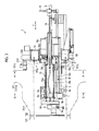
- Fig. 3 is a side sectional view showing the water jet peening device.
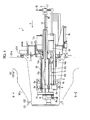
- Fig. 4 is a side sectional view showing another use state of the water jet peening device.
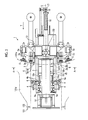
- Fig. 5 is a plan view showing the water jet peening device.
- Fig. 6 is a sectional view taken along line A-A in Figs. 3 and 5 .
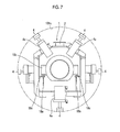
- Fig. 7 is a sectional view taken along line B-B in Fig. 4 .
- Fig. 8 is a sectional view taken along line C-C in Fig. 3 .
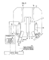
- Fig. 9 is a front view showing a pressing movement mechanism of the water jet peening device.
- Fig. 9 is a front view showing a pressing movement mechanism of the water jet peening device.
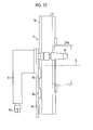
- Fig. 10 is a side view showing the pressing movement mechanism of the water jet peening device.
- Fig. 11 is a schematic view showing an operation of the water jet peening device.
- Fig. 12 is a sectional view showing contact detection means of the water jet peening device.
- a water jet peening device 1 is inserted into and fixed to the inner portions of the inlet side tube support 101c or the outlet side tube support 101d of the reactor vessel 101 (reactor vessel body 101a).
- a working floor 151 is provided in a reactor building (not shown), a cavity 152 is provided below the working floor 151, and cooling water is stored in the cavity 152.
- the reactor vessel 101 is disposed inside the cavity 152 and is supported in a suspended manner.
- a pair of parallel guide rails 155 is provided on both sides of the cavity 152, and a mobile crane 156 is movably supported by the rails 155.
- the mobile crane 156 is movable in one direction (right-left direction in Fig. 2 ) in a horizontal direction, and an electric hoist 157 which is movable in the other direction (a direction orthogonal to the paper surface in Fig.
- the electric hoist 157 includes a hook 158 which can be lifted and lowered in the vertical direction.
- An installation pole 159 is suspended via the hook 158.
- the installation pole 159 is a long member and has a predetermined length, and the water jet peening device 1 can be connected to the lower end portion of the installation pole 159.
- the installation pole 159 is configured of a plurality of division poles, and the flange portions of the upper ends and the lower ends of the division poles come into close contact with each other, and it is possible to fasten the upper ends and the lower ends by a plurality of swing bolts.
- each of the tube supports 101c and 101d includes an opening portion 101f on a wall surface 101e inside the reactor vessel 101 and is provided to extend in a horizontal direction (or including a horizontal component).
- the water jet peening device 1 is inserted into and fixed to the inner portions of the tube supports 101c and 101d from the opening portions 101f.
- the installation pole 159 is used as an installation tool used to install the water jet peening device 1.
- the present invention is not limited to this, and for example, a wire, a cable, a lope, or the like may be used.
- the water jet peening device 1 includes a frame 2 which is connected to the installation pole 159.
- the frame 2 has an outer shape which can be inserted into the inner portions of the tube supports 101c and 101d and is formed in a tube shape extending along an insertion direction T.
- An external abutment member 3, an internal abutment member 4, suction means 5, abutment detection means 6, photographing means 7, a spray nozzle 8, a pressing movement mechanism 9, and a guide portion 10 are provided on the frame 2.
- the external abutment member 3 abuts the wall surface 101e.
- the external abutment member 3 is attached to a support member 13, which extends to the outside of the frame 2 and is fixed to the frame 2, so as to protrude toward the tip on the insertion tip side (insertion direction T side) of the frame 2.
- the external abutment members 3 are disposed at a total of six locations, that is, two locations one each on the right and left above the support member 13, and four locations two each on the right and left below the support member 13.
- the two upper external abutment members 3 and the two lower external abutment members 3 which are slightly close to the upper side are configured so as to change the positions of the tips toward the insertion tip side of the frame 2 according to presence or absence of spacers 3a.
- the two lower external abutment member 3 which are slightly close to the lower side are configured so as to be movable to change the positions of tips toward the insertion tip side of the frame 2 by an actuator (pneumatic cylinder) 3b.
- the shape of the opening portion 101f of the inlet side tube support 101c is different from that of the opening portion 101f of the outlet side tube support 101d. That is, a protrusion 101g is formed on the outlet side tube support 101d, and the inlet side tube support 101c and the outlet side tube support 101d are distinguished according to the presence or the absence of the protrusion 101g.
- the plurality of internal abutment members 4 are provided on the periphery centered around the frame 2 (center axis S) on a portion in which the frame 2 is inserted into the inner portions of the tube supports 101c and 101d, and are provided to protrude toward the tips on the outside in a radial direction.
- the internal abutment members 4 are disposed at a total of seven locations, that is, as shown in Fig.
- the internal abutment members 4 are configured so as to be movable forward and rearward in the radial direction centered around the frame 2 by an actuator (pneumatic cylinder) 4a.
- the internal abutment members 4 which are moved forward and rearward by the actuator 4a abut the inner surfaces of the tube supports 101c and 101d.
- the one internal abutment member 4 below the center position of the frame 2 is positioned below the two internal abutment members 4 positioned at the front side in the insertion direction T of the frame 2 on the right and the left of the upper side, and is used to align the center position of the frame 2 with the center position of the inlet side tube support 101c when the internal abutment members 4 are inserted into the inlet side tube support 101c at five locations including the above-described three locations and two internal abutment members 4 on both sides in the vicinity of the center position of the frame 2. Meanwhile, as shown in Figs.
- a tire 4b rolling in the insertion direction T is provided as the internal abutment member 4, which does not move forward and rearward, on the rear side of one internal abutment member 4 below the center position of the frame 2.
- the tire 4b is positioned below two internal abutment members 4 on the rear side in the insertion direction T of the frame 2 on the right and left of the upper side, and is used to align the center position of the frame 2 with the center position of the outlet side tube support 101d when the two internal abutment members 4 are inserted into the outlet side tube support 101d at five locations on both sides of the height in the vicinity of the center position of the frame 2.
- the hole shape of the inlet side tube support 101c is different from that of the outlet side tube support 101d.
- an inclination is formed on the inner surface so that the diameter of the inlet side tube support 101c decreases toward the inner portion, and the inclination is not formed on the outlet side tube support 101d. Accordingly, the internal abutment members 4 are used to align the center position of the frame 2 with the center positions of the tube supports 101c and 101d according to the presence and absence of the inclination.
- the suction means 5 is provided so as to be sucked to the wall surface 101e when the frame 2 is inserted into predetermined positions inside the tube supports 101c and 101d.
- the suction means 5 is attached to the support member 13 so that a suction surface of the suction means is directed to the insertion tip side (insertion direction T side) of the frame 2.
- the suction means 5 is disposed at a total of four locations, that is, two location one each on the right and left above the support member 13 and two locations one each on the right and left below the support member 13.
- the suction means 5 is provided so as to be movable along the insertion direction T by an actuator (pneumatic cylinder) 5a. Moreover, as shown in Fig. 5 , the suction means 5 is provided so as to be swung in the right-left direction with respect to a rod 5b of the actuator 5a to correspond to the inclination of the wall surface 101e.
- the abutment detection means 6 detects that the external abutment members 3 abut the wall surface 101e.
- the abutment detection means 6 is disposed on the side portions of the upper external abutment member 3 and is attached to the support member 13 so that the tip of a contactor 6a is directed to the insertion tip side (insertion direction T side) of the frame 2.
- the contactor 6a is provided so as to be movable along the insertion direction T with respect to a casing 6b, and is biased by a spring (not shown) so as to protrude toward the insertion direction T side at all times.
- a proximity sensor (not shown) is provided inside the casing 6b, and detects that the contactor 6a moves in a direction opposite to the insertion direction T.
- the contactor 6a moves in a direction opposite to the insertion direction T.
- the abutment detection means 6 detects that the external abutment members 3 abut the wall surface 101e.
- the abutment detection means 6 since the abutment detection means 6 is provided, it is possible to recognize the state where the external abutment members 3 abut the wall surface 101e, that is, an intent in which the frame 2 inserted inside the tube supports 101c and 101d is positioned by the external abutment members 3.
- the photographing means 7 is disposed at a total of four locations one each with respect to the support members 13, that is, the upper, lower, right, left locations of the frame 2.
- the photographing means 7 includes a camera 7a and an illumination 7b, and the camera and illumination are provided so as to be directed toward the insertion tip side (insertion direction T) of the frame 2.
- the photographing means 7 photographs the insertion tip side of the frame 2 inserted into the tube supports 101c and 101d, from the insertion rear end side.
- the spray nozzle 8 sprays water jet to inner surfaces of the tube supports 101c and 101d. As shown in Figs. 3 , 4 , and 9 , the spray nozzle 8 is disposed at a nozzle support portion 14 provided on the insertion tip side of the frame 2 so that a spray port 8a spraying the water jet is directed toward the inner surfaces of the tube supports 101c and 101d.
- the nozzle support portion 14 is rotatably supported around the center axis S (center axes of the tube supports 101c and 101d) of the frame 2 with respect to the frame 2.
- the nozzle support portion 14 is supported by the nozzle rotating mechanism 15.
- the nozzle rotating mechanism 15 includes a rotating shaft portion 15a.
- the nozzle support portion 14 is attached to the rotating shaft portion 15a, and the rotating shaft portion 15a is rotatably supported about the center axis S with respect to the frame 2.
- the rotating shaft portion 15a is formed in a cylindrical shape extending along the center axis S, and a driven gear 15b is attached to the outer circumference of the rotating shaft portion 15a.
- the driven gear 15b engages with a driving gear 15d which is provided on an output axis of a rotating motor 15c fixed to the frame 2.
- the rotation of the driving gear 15d is transmitted to the driven gear 15b by the driving of the rotating motor 15c, and thus, the rotating shaft portion 15a is rotated.
- the nozzle support portion 14 supported by the rotating shaft portion 15a is rotated accompanying the spray nozzle 8.
- the spray nozzle 8 rotates and moves along a predetermined movement trajectory around the center axis S.
- the spray nozzle 8 is disposed on the nozzle support portion 14 so that the spray port 8a spraying the water jet is directed toward the inner surfaces of the tube supports 101c and 101d. Accordingly, in the spray nozzle 8 which is rotated and moved by the nozzle rotating mechanism 15, the spray port 8a rotates and moves along the predetermined movement trajectory in the circumferential direction of the tube supports 101c and 101d while being directed toward the inner surfaces of the tube supports 101c and 101d. That is, in the direction of the spray port 8a of the spray nozzle 8, a perpendicular downward rotation angle is defined as 0°, and the spray port 8a is rotated 360° along the circumferential directions of the tube supports 101c and 101d via a perpendicular upward rotation angle of 180°.
- the movement position of the spray port 8a in the movement trajectory is detected by nozzle position detection means 15e (refer to Fig. 9 ) provided in the nozzle rotating mechanism 15.
- the rotating motor 15c is configured of a servo motor, and thus, the movement position of the spray port 8a in the movement trajectory is detected by the nozzle position detection means 15e.
- a high-pressure water supply pipe 16 for supplying high-pressure water to the spray nozzle 8 is disposed inside the rotating shaft portion 15a.
- the high-pressure water supply pipe 16 is provided to extend along the center axis S from the insertion rear end side of the frame 2 in the rotating shaft portion 15a, and a swivel bearing 17 is disposed on the extended end portion.
- the high-pressure water supply pipe 16 extends upward from the swivel bearing 17, and as shown in Fig. 2 , is connected to a high-pressure water pump 160 which is installed on the working floor 151 and feeds high-pressure water.
- the high-pressure water fed from the high-pressure water pump 160 is supplied to the spray nozzle 8 via the high-pressure water supply pipe 16, and is sprayed to the inner surfaces of the tube supports 101c and 101d from the spray port 8a as water jet.
- the spray nozzle 8 is rotated around the center axis S by the nozzle rotating mechanism 15, and thus, the water jet is sprayed to the inner surfaces of the tube supports 101c and 101d along the circumstantial directions of the tube supports 101c and 101d.
- the rotating shaft portion 15a is rotated by the nozzle rotating mechanism 15, the high-pressure water supply pipe 16 inside the rotating shaft portion 15a is also rotated.
- the swivel bearing 17 is provided in the intermediate of the high-pressure water supply pipe 16, it is possible to prevent the high-pressure water supply pipe 16 from being twisted.
- the nozzle support portion 14 is supported so as to be movable forward and rearward along the center axis S (center axes of the tube supports 101c and 101d) of the frame 2 with respect to the frame 2.
- the nozzle support portion 14 is supported by a nozzle forward/rearward movement mechanism 18 which is provided inside the frame 2.
- the nozzle forward/rearward movement mechanism 18 includes slide rails 18a, a slide frame 18b, sliders 18c, a ball screw 18d, a nut portion 18e, and a forward/rearward movement motor 18f.
- a pair of slide rails 18a extends so as to be parallel with the center axis S of the frame 2 and is provided right and left.
- the slide frame 18b is supported so as to be moveable in the extension directions of the slide rails 18a with respect to the slide rails 18a.
- the sliders 18c are attached via the slide rails 18a, and fixed to the slide frame 18b.
- the ball screw 18d is provided to extend along the center axis S of the frame 2 so as to be parallel with the slide rails 18a, and is rotatably supported about an axis parallel with the center axis S with respect to the frame 2.
- the nut portion 18e is screwed to the ball screw 18d.
- the forward/rearward movement motor 18f is connected to the ball screw 18d to rotate the ball screw 18d.
- the sliders 18c move accompanying the slide frame 18b in the extension direction (the direction parallel with the center axis S) of the ball screw 18d along with the nut portion 18e.
- the rotating shaft portion 15a of the above-described nozzle rotating mechanism 15 which supports the nozzle support portion 14 is attached to the slide frame 18b. That is, the rotating shaft portion 15a moves in the direction parallel with the center axis S along with the slide frame 18b accompanying the nozzle support portion 14 to which the spray nozzle 8 is supported. As a result, the spray nozzle 8 moves forward and rearward along the center axis S.
- the rotating shaft portion 15a is rotated around the center axis S, and thus, the rotating shaft portion 15a is attached in the state where the rotating shaft portion 15a can rotate with respect to the slide frame 18b.
- the rotating shaft portion 15a is provided so that the driven gear 15b is movable along the center axis S.
- the movement of the driven gear 15b along the center axis S is regulated in the state where the meshing between driven gear 15b and the driving gear 15d is maintained. Accordingly, the transmission of the driving for rotating the rotating shaft portion 15a is constantly maintained when the rotating shaft portion 15a moves forward and rearward by the nozzle forward/rearward movement mechanism 18. That is, the rotating shaft portion 15a is provided so that the rotating shaft portion 15a itself is rotated and the forward and rearward movements thereof along the center axis S are performed.
- the pressing movement mechanism 9 presses and moves the spray nozzle 8 along the direction in which the water jet is sprayed from the spray port 8a.
- the pressing movement mechanism 9 is provided on the nozzle support portion 14, and includes slide rails 9a, sliders 9b, a slide frame 9c, and actuators 9d.
- the pair of slide rails 9a is provided to extend in the direction orthogonal to the center axis S.
- the sliders 9b are supported so as to be movable in the extension directions of the slide rails 9a.
- the slide frame 9c is supported by the sliders 9b, and is provided so as to be movable in the extension directions of the slide rails 9a.
- the spray nozzle 8 is fixed to the slide frame 9c so that the spray port 8a is directed in the extension directions of the slide rails 9a.
- Each of the actuators 9d is provided on the nozzle support portion 14 so as to be disposed on the side portion of each slide rail 9a, and is connected to the slide frame 9c.
- the actuator 9d moves the slide frame 9c in the extension direction of the slide rail 9a, and in the present embodiment, is configured of a pneumatic cylinder.
- the actuator 9d is not limited to the pneumatic cylinder, and may be any cylinder as long as it can move the slide frame 9c in the extension directions of the slide rails 9a.
- the slide frame 9c moves in the direction orthogonal to the center axis S accompanying the spray nozzle 8 by the driving of the actuator 9d. That is, in the state where the spray port 8a of the spray nozzle 8 opposes the inner surfaces of the tube supports 101c and 101d, the spray port 8a is pressed and moved so that the spray port 8a approaches and is separated from the inner surfaces of the tube supports 101c and 101d. As a result, a spray distance of the water jet which is the distance from the spray port 8a to the inner surfaces of the tube supports 101c and 101d is adjusted. As the spray distance of the water jet, 130 mm ⁇ 10 mm is defined as a predetermined distance.
- the guide portion 10 is fixed to the slide frame 9c of the pressing movement mechanism 9 along with the spray nozzle 8. Accordingly, the guide portion 10 performs the rotational movement, forward and rearward movements, and the press movement along with the spray nozzle 8.
- the guide portion 10 is provided so as to be parallel with the spray nozzle 8, and a tip portion 10a is disposed at a position aligned with the predetermined distance over which the water jet J is sprayed from the spray port 8a. That is, the guide portion 10 is pressed and moved along with the spray nozzle 8 by the pressing movement mechanism 9, and as shown in Fig. 11 , the tip portion 10a comes into contact with the inner surfaces of the tube supports 101c and 101d, and thus, a predetermined distance L over which the water jet J is sprayed from the spray port 8a is maintained.
- the spray nozzle 8 is moved forward and rearward to the position, at which the spray port 8a is directed toward predetermined inner surfaces of the tube supports 101c and 101d subjected to the water jet peening, by the nozzle forward/rearward movement mechanism 18. Thereafter, the spray nozzle 8 is pressed and moved until the tip portion 10a of the guide portion 10 comes into contact with the inner surfaces of the tube supports 101c and 101d by the pressing movement mechanism 9.
- the spray nozzle 8 is rotated and moved by the nozzle rotating mechanism 15 while the water jet is sprayed from the spray port 8a of the spray nozzle 8. Accordingly, the water jet peening is constructed on the predetermined inner surfaces of the tube supports 101c and 101d.
- contact detection means 19 is provided in order to detect contact of the tip portion 10a in the guide portion 10.
- the contact detection means 19 is configured of tip portion movement detection means 19A.
- the tip portion movement detection means 19A is provided so that the tip portion 10a moves in a direction in which the tip portion 10a is pressed and moved to the main body portion 10b.
- the tip portion 10a is biased so as to constantly protrude by a spring 10c which is disposed inside the main body portion 10b.
- a proximity sensor 10d facing the tip portion 10a is provided inside the main body portion 10b. The proximity sensor 10d detects that the tip portion 10a approaches the inner surfaces of the tube supports 101c and 101d, that is, the tip portion 10a comes into contact with the inner surfaces of the tube supports 101c and 101d and the tip portion 10a is pushed into the inner portion of the main body portion 10b.
- detection signals in which the contact of the tip portion 10a in the guide portion 10 is detected by the contact detection means 19 (tip portion movement detection means 19A), are input to control means 20.
- the control means 20 determines that the tip portion 10a of the guide portion 10 comes into contact with the inner surfaces of the tube supports 101c and 101d by the input of the detection signals generated by the contact of the tip portion 10a in the guide portion 10.
- the contact detection means 19 (tip portion movement detection means 19A) is provided, it is possible to confirm that the tip portion 10a of the guide portion 10 comes into contact with the inner surfaces of the tube supports 101c and 101d. Accordingly, it is possible to securely maintain the predetermined distance L over which the water jet is sprayed from the spray port 8a, and it is possible to improve construction accuracy of the water jet peening.
- the surfaces to be constructed on which the water jet peening is performed are the inner surfaces of the tube supports 101c and 101d which extend to include horizontal components. Accordingly, the direction of the spray port 8a is directed upward and downward so that the spray port 8a is directed toward the inner surfaces of the tube supports 101c and 101d according to the movement trajectory of the spray nozzle 8 which is rotated and moved around the center axis S by the nozzle rotating mechanism 15. In addition, in upward water jet peening in which the spray port 8a is directed upward, since the spray nozzle 8 is pushed downward by a reaction force and gravity of the water jet, the pressing force of the guide portion 10 decreases.
- the tip portion 10a of the guide portion 10 is separated from the inner surfaces of the tube supports 101c and 101d, the spray distance L of the water jet from the spray port 8a to the inner surfaces of the tube supports 101c and 101d cannot be maintained, and effects of the water jet peening with respect to the inner surfaces of the tube supports 101c and 101d decrease. Meanwhile, in downward water jet peening in which the spray port 8a is directed downward, since the spray nozzle 8 is pushed downward by the gravity, the pressing force of the guide portion 10 increases.
- control means 20 inputs the movement position of the spray port 8a which is detected by the nozzle position detection means 15e, and controls the pressing force of the guide portion 10 generated by the pressing movement mechanism 9, on the basis of the movement position of the spray port 8a.
- the control means 20 inputs the detection signals of the movement position (rotation angle) of the spray port 8a in the movement trajectory of the spray nozzle 8, from the nozzle position detection means 15e.
- the actuator 9d is configured of a pneumatic cylinder and includes a pneumatic unit 9e which operates the pneumatic cylinder.
- air pressure of the pneumatic cylinder is adjusted by an electro-pneumatic regulator 9f, and air pressure command is obtained from the signals by the control means 20.
- the control means 20 sets air pressure command in advance according to the movement position (rotation angle) of the spray port 8a, and outputs the signals of the air pressure command to the electro-pneumatic regulator 9f.
- the control means 20 stores air pressure in advance, which is calculated considering the reaction force and the gravity of the water jet in the movement position (rotation angle) of the spray port 8a in the movement trajectory of the spray nozzle 8.
- the control means 20 controls the electro-pneumatic regulator 9f according to the movement position of the spray port 8a input from the nozzle position detection means 15e, and outputs voltage corresponding to the required air pressure to the actuator 9d. That is, in the movement position of the spray port 8a, when the direction of the spray port 8a is the movement position including the upward component, as shown in Fig.
- the control means 20 controls the electro-pneumatic regulator 9f of the pneumatic unit 9e in the pressing movement mechanism 9 to increase the air pressure, and increase the pressing force by which the guide portion 10 is pressed upward (to the inners surfaces of the tube supports 101c and 101d) against the reaction force and gravity of the water jet.
- the air pressure gradually increases from the horizontal state, the highest air pressures is set at the vertical position, and the air pressure gradually decreases while being returned to the horizontal state.
- the spray distance L of the water jet from the spray port 8a to the inner surfaces of the tube supports 101c and 101d is maintained, and it is possible to maintain effects of the water jet peening with respect to the inner surfaces of the tube supports 101c and 101d.
- the direction of the spray port 8a is the movement position including the downward component, as shown in Fig.
- the control means 20 controls the electro-pneumatic regulator 9f of the pneumatic unit 9e in the pressing movement mechanism 9 to decrease the air pressure, and decreases the pressing force by which the guide portion 10 is pressed downward (to the inners surfaces of the tube supports 101c and 101d) against the spray nozzle 8 being pushed downward by the gravity.
- the air pressure gradually decreases from the horizontal state, the lowest air pressures is set at the vertical position, and the air pressure gradually increases while being returned to the horizontal state.
- the load applied to the nozzle rotating mechanism 15 decreases, and thus, it is possible to smoothly perform the rotational movement of the spray nozzle 8. That is, regardless of the movement position of the spray port 8a, it is possible to keep the contact pressure of the tip portion 10a in the guide portion 10 so as to be constant.
Landscapes
- Engineering & Computer Science (AREA)
- Physics & Mathematics (AREA)
- Plasma & Fusion (AREA)
- General Engineering & Computer Science (AREA)
- High Energy & Nuclear Physics (AREA)
- Mechanical Engineering (AREA)
- Human Computer Interaction (AREA)
- Manufacturing & Machinery (AREA)
- General Physics & Mathematics (AREA)
- Automation & Control Theory (AREA)
- Monitoring And Testing Of Nuclear Reactors (AREA)
- Nozzles (AREA)
Abstract
Description
- The present invention relates to a water jet peening device for repairing an inner surface of a tube support provided in a nuclear power generation plant.
- For example, in a nuclear power generation plant including a Pressurized Water Reactor (PWR), a light water which is a primary cooling water is used as a nuclear reactor coolant and a neutron moderator to generate high-temperature and high-pressure water which is not boiled over the entire reactor core, the high-temperature and high-pressure water is fed to a steam generator to generate steam by heat exchange, the steam is fed to a turbine generator, and thus, electricity is generated.
- In the nuclear power generation plant, in order to secure sufficient stability and reliability of the Pressurized Water Reactor, it is necessary to examine various structures or the like periodically. In addition, when the examination is performed and defects are found, necessary locations related to the defects are repaired. For example, in the Pressurized Water Reactor, the reactor vessel body includes an outlet side tube support for supplying the primary cooling water to the steam generator and an inlet side tube support for adsorbing the primary cooling water which is heat-exchanged by the steam generator. A primary cooling water pipe communicating with the steam generator is connected to the tube support by welding. In addition, since a material of the tube support is different from that of the primary cooling water pipe, a safe end pipe is connected between the tube support and the primary cooling water pipe by welding.
- Residual tensile stress generated in a welding portion of the tube support and the periphery thereof may cause stress corrosion cracking. Accordingly, in the related art, there is a water jet peening technology for preventing the stress corrosion cracking by improving the residual tensile stress on the surface into residual compressive stress. In this water jet peening, the residual tensile stress on a surface of a metal member is improved into the residual compressive stress by spraying high-pressure water including cavitation air bubbles on the surface of the metal member in water. For example, as the water jet peening device, there is a water jet peening device disclosed in
PTL 1 below. - In the water jet peening device disclosed in
PTL 1, in order to keep a distance between a spray nozzle and a surface to be constructed so as to be constant, a guide is attached around the spray nozzle, a slight pressing force is applied to the guide by a pressing device, and the guide comes into contact with the surface to be constructed to trace the shape of the surface to be constructed. - [PTL 1]
Japanese Unexamined Patent Application Publication No. 6-114735 - In the water jet peening device disclosed in
PTL 1, water jet peening is performed on a welding portion of an instrumentation tube support penetrating a lower mirror of a reactor vessel body and the periphery thereof in a state where a spray nozzle is directed downward or a direction inclined to the instrumentation tube support. However, in the case of the tube support of the above-described reactor vessel body, the water jet peening is performed on not only the lower portion of the tube support but also the upper portion thereof. Accordingly, in the water jet peening with respect to the upper portion, the spray nozzle is pushed downward by a reaction force and gravity of the water jet, the pressing force of the guide decreases, and thus, the contact between the surface to be constructed and the guide cannot be maintained, that is, there is a concern that the distance between the spray nozzle and the surface to be constructed cannot be kept to be constant. Meanwhile, in the water jet peening with respect to the lower portion, the spray nozzle is pushed downward by the gravity, the pressing force of the guide increases, a load is applied with respect to the tracing of the shape of the surface to be constructed, and there is a concern that the spray nozzle cannot be moved smoothly. As a result, it is not possible to perform the water jet peening in a suitable state of construction. - The present invention is made to solve the above-described problems, and an object thereof is to provide a water jet peening device capable of keeping the distance between the spray nozzle and the surface to be constructed so as to be constant, moving the spray nozzle smoothly, and performing the water jet peening in a suitable state of construction.
- In order to achieve the object, according to a first aspect of the present invention, there is provided a water jet peening device in which a spray nozzle for spraying water jet is provided so as to be movable along a predetermined movement trajectory so that a spray port of the spray nozzle is directed upward and downward, including: a guide portion which includes a tip portion disposed at a position aligned with a predetermined distance over which the water jet is sprayed from the spray port, and is provided so as to be movable with the spray nozzle along the movement trajectory; a pressing movement mechanism which presses and moves the spray nozzle and the guide portion along a direction in which the water jet is sprayed from the spray port; nozzle position detection means for detecting a movement position of the spray port in the movement trajectory; and control means for controlling a pressing force of the pressing movement mechanism on the guide portion, on the basis of the movement position of the spray port detected by the nozzle position detection means.
- According to the water jet peening device, for example, when the direction of the spray port is the movement position including an upward component, the control means controls the pressing movement mechanism so as to increase the pressing force, and increases the pressing force which presses the guide portion upward against the reaction force and the gravity of the water jet. Accordingly, since it is possible to prevent the tip portion of the guide portion from being separated from the surface to be constructed, the spray distance of the water jet between the spray port and the surface to be constructed is maintained, and it is possible to maintain an operation of the water jet peening with respect to the surface to be constructed. Meanwhile, when the direction of the spray port is the movement position including a downward component, the control means controls the pressing movement mechanism, and decreases a pressing force by which the guide portion is pressed downward against the spray nozzle being pushed downward by the gravity. Accordingly, since it is possible to prevent a contact pressure when the tip portion of the guide portion comes into contact with the surface to be constructed from increasing, the spray nozzle can smoothly move along the movement trajectory of the spray nozzle. That is, regardless of the movement position of the spray port, it is possible to keep the contact pressure of the tip portion of the guide portion so as to be constant.
- According to a second aspect of the invention, the water jet peening device related to the first aspect may further include: contact detection means for detecting contact of the tip portion of the guide portion.
- According to the water jet peening device, since the contact detection means is provided, it is possible to confirm that the tip portion of the guide portion comes into contact with the surface to be constructed, and thus, it is possible to securely maintain a predetermine distance over which the water jet is sprayed from the spray port, and it is possible to improve construction accuracy of the water jet peening.
- According to a third aspect of the invention, in the water jet peening device related to the first or the second aspect, the water jet peening device may spray the water jet to an inner surface of a tube support which includes an opening portion on a wall surface and extends to include a horizontal component, and the water jet peening device may further include: a frame which supports the spray nozzle and the guide portion and is provided so as to be inserted into the inner portion of the tube support; an external abutment member which is provided on the frame and abuts the wall surface when the frame is inserted into a predetermined position inside the tube support; internal abutment members which are provided at a plurality of locations around the frame in a portion of the frame inserted into the inner portion of the tube support and is provided so as to be movable forward and rearward in a radial direction centered around the frame; and suction means which is provided on the frame and can be sucked to the wall surface when the frame is inserted into the predetermined position inside the tube support.
- According to the water jet peening device, since the external abutment member is provided, it is possible to position the state where the frame is inserted into the predetermined position inside the tube support. In addition, since the internal abutment member is provided, it is possible to align a center position of the frame with a center position of the tube support. Moreover, since the suction means is provided, it is possible to maintain the state where the frame inserted into the inner portion of the tube support is positioned by the external abutment member, and the state where the center position of the frame is aligned with the center position of the tube support by the internal abutment member.
- According to a fourth aspect of the invention, the water jet peening device related to the third aspect may further include: abutment detection means for detecting abutment of the external abutment member on the wall surface.
- According to the water jet peening device, since the abutment detection means is provided, it is possible to recognize the state where the external abutment member abuts the wall surface, that is, an intent that the frame inserted into the inner portion of the tube support by the external abutment member is positioned.
- According to a fifth aspect of the invention, the water jet peening device related to the third or the fourth aspect may further include: photographing means for photographing an insertion tip side of the frame, which is inserted into the tube support, from an insertion rear end side, and the photographing means may be provided on the frame.
- According to the water jet peening device, since the photographing means is provided, it is possible to monitor the state of the frame inserted into the tube support. Advantageous Effects of Invention
- According to the present invention, it is possible to keep a distance between a spray nozzle and a surface to be constructed so as to be constant, smoothly move the spray nozzle, and perform water jet peening in a suitable state of construction.
-
-
Fig. 1 is a schematic configuration view showing an example of a nuclear power generation plant. -
Fig. 2 is a schematic view showing an installation state of water jet peening device. -
Fig. 3 is a side sectional view showing the water jet peening device. -
Fig. 4 is a side sectional view showing another use state of the water jet peening device. -
Fig. 5 is a plan view showing the water jet peening device. -
Fig. 6 is a sectional view taken along line A-A inFigs. 3 and5 . -
Fig. 7 is a sectional view taken along line B-B inFig. 4 . -
Fig. 8 is a sectional view taken along line C-C inFig. 3 . -
Fig. 9 is a front view showing a pressing movement mechanism of the water jet peening device. -
Fig. 10 is a side view showing the pressing movement mechanism of the water jet peening device. -
Fig. 11 is a schematic view showing an operation of the water jet peening device. -
Fig. 12 is a sectional view showing contact detection means of the water jet peening device. Description of Embodiments - Hereinafter, an embodiment of the present invention will be described in detail with reference to the drawings. In addition, the present invention is not limited by the embodiment. Moreover, components in the embodiment below include components replaceable by a person skilled in the art or substantially the same components.
-
Fig. 1 is a schematic configuration showing an example of a nuclear power generation plant. The nuclear power generation plant shown inFig. 1 includes a Pressurized Water Reactor (PWR). In the nuclear power generation plant, in areactor container 100, areactor vessel 101, apressurizer 102, asteam generator 103, and a primarycooling water pump 104 of the Pressurized Water Reactor are sequentially connected to one another by a primarycooling water pipe 105, and a circulation path of primary cooling water is configured. - A
fuel assembly 120 is stored inside thereactor vessel 101 in a sealed state, and includes areactor vessel body 101a and areactor vessel cover 101b which is mounted on the upper portion of thereactor vessel body 101a to insert and extract thefuel assembly 120. An inletside tube support 101c and an outletside tube support 101d for supplying and discharging light water which is primary cooling water are provided on the upper portion of thereactor vessel body 101a. A primarycooling water pipe 105 is connected to the outletside tube support 101d so that the outlet side tube support communicates with an inletside water chamber 103a of asteam generator 103. In addition, the primarycooling water pipe 105 is connected to the inletside tube support 101c so that the inlet side tube support communicates with an outletside water chamber 103b of thesteam generator 103. - In the lower portion of the
steam generator 103 which is configured in a semispherical shape, the inletside water chamber 103a and the outletside water chamber 103b are provided so as to be partitioned by apartition plate 103c. The inletside water chamber 103a and the outletside water chamber 103b are partitioned with the upper portion side of thesteam generator 103 by atube plate 103d provided on the ceiling portions of thechambers heat transfer pipe 103e having an inverted U shape is provided on the upper portion side of thesteam generator 103. End portions of theheat transfer pipe 103e are supported by thetube plate 103d so that theheat transfer pipe 103e is connected to the inletside water chamber 103a and the outletside water chamber 103b. In addition, the inletside water chamber 103a is connected to the inlet side primarycooling water pipe 105, and the outletside water chamber 103b is connected to the outlet side primarycooling water pipe 105. Moreover, in thesteam generator 103, an outlet side secondarycooling water pipe 106a is connected to the upper end of the upper portion side which is partitioned by thetube plate 103d, and an inlet side secondarycooling water pipe 106b is connected to the side portion of the upper portion side. - In addition, in the nuclear power generation plant, the
steam generator 103 is connected to asteam turbine 107 via the secondarycooling water pipes reactor container 100, and thus, a circulation path of secondary cooling water is configured. - The
steam turbine 107 includes a high-pressure turbine 108 and a low-pressure turbine 109, and agenerator 110 is connected to thesteam turbine 107. Moreover, amoisture separating heater 111 is branched from the secondarycooling water pipe 106a and is connected to the high-pressure turbine 108 and the low-pressure turbine 109. In addition, the low-pressure turbine 109 is connected to acondenser 112. Thecondenser 112 is connected to the secondarycooling water pipe 106b. As described above, the secondarycooling water pipe 106b is connected to thesteam generator 103 and reaches thesteam generator 103 from thecondenser 112, and acondensate pump 113, a low-pressurewater supply heater 114, adeaerator 115, a mainwater supply pump 116, and a high-pressurewater supply heater 117 are provided in the secondarycooling water pipe 106b. - Accordingly, in the nuclear power generation plant, the primary cooling water is heated in the
reactor vessel 101 to increase the temperature and the pressure, is pressurized in thepressurizer 102 to maintain the pressure so as to be constant, and is supplied to thesteam generator 103 via the primarycooling water pipe 105. In thesteam generator 103, heat exchange between the primary cooling water and the secondary cooling water is performed, and thus, the secondary cooling water is evaporated, and steam is generated. The cooled primary cooling water after the heat exchange is recovered to the primarycooling water pump 104 side via the primarycooling water pipe 105, and is returned to thereactor vessel 101. Meanwhile, the secondary cooling water evaporated by the heat exchange is supplied to thesteam turbine 107. In thesteam turbine 107, themoisture separating heater 111 removes moisture from the exhaust of the high-pressure turbine 108, and after the exhaust is further heated so as to be overheated, the exhaust is fed to the low-pressure turbine 109. Thesteam turbine 107 is driven by steam of the secondary cooling water, the power is transmitted to thegenerator 110, and electricity is generated. The steam supplied to the driving of the turbine is discharged to thecondenser 112. In thecondenser 112, cooling water (for example, sea water) taken by apump 112b via anintake pipe 112a and the steam discharged from the low-pressure turbine 109 are heat-exchanged, and thus, the steam is condensed so as to be returned to a low-pressure saturated liquid. The cooling water used in the heat exchange is discharged from adrain pipe 112c. In addition, the condensed saturated liquid becomes the secondary cooling water and is discharged to the outside of thecondenser 112 via the secondarycooling water pipe 106b by thecondensate pump 113. In addition, the secondary cooling water passing through the secondarycooling water pipe 106b is heated by low-pressure steam extracted from the low-pressure turbine 109 in the low-pressurewater supply heater 114, and after impurities of the secondary cooling water such as dissolved oxygen or non-condensable gas (ammonia gas) are removed by thedeaerator 115, the secondary cooling water is fed by the mainwater supply pump 116. In addition, for example, after the secondary cooling water is heated by high-pressure steam extracted from the high-pressure turbine 108 using the high-pressurewater supply heater 117, the secondary cooling water is returned to thesteam generator 103. - In the Pressurized Water Reactor of the nuclear power generation plant configured in this way, as described above, in the
reactor vessel 101, the primarycooling water pipe 105 is connected to the inletside tube support 101c and the outletside tube support 101d. Moreover, since materials of the inletside tube support 101c and the outletside tube support 101d are different from a material of the primarycooling water pipe 105, asafe end pipe 121 is connected to a portion therebetween by welding (groove welding portion 122) (refer toFigs. 3 and4 ). - Accordingly, tensile stress may remain in the
groove welding portion 122 and the periphery thereof, and thus, probability of stress corrosion cracking occurring due to use for a long period increases. Therefore, the residual tensile stress of thegroove welding portion 122 which is an object to be repaired and the inner surfaces of the tube supports 101c and 101d which are the peripheries thereof is improved to residual compressive stress by a water jet peening device which is a device for repairing the reactor, and thus, the stress corrosion cracking is prevented. The water jet peening device sprays high-pressure water including cavitation air bubbles on a surface of a metal member in water, and improves the residual tensile stress of the surface of the metal member to the residual compressive stress. - In addition, when the residual tensile stress of the
groove welding portion 122 and the inner surfaces of thetube support tube support -
Fig. 2 is a schematic view showing an installation state of the water jet peening device.Fig. 3 is a side sectional view showing the water jet peening device.Fig. 4 is a side sectional view showing another use state of the water jet peening device.Fig. 5 is a plan view showing the water jet peening device.Fig. 6 is a sectional view taken along line A-A inFigs. 3 and5 .Fig. 7 is a sectional view taken along line B-B inFig. 4 .Fig. 8 is a sectional view taken along line C-C inFig. 3 .Fig. 9 is a front view showing a pressing movement mechanism of the water jet peening device.Fig. 10 is a side view showing the pressing movement mechanism of the water jet peening device.Fig. 11 is a schematic view showing an operation of the water jet peening device.Fig. 12 is a sectional view showing contact detection means of the water jet peening device. - As shown in
Fig. 2 , a waterjet peening device 1 is inserted into and fixed to the inner portions of the inletside tube support 101c or the outletside tube support 101d of the reactor vessel 101 (reactor vessel body 101a). - Moreover, in the nuclear power generation plant, a working
floor 151 is provided in a reactor building (not shown), acavity 152 is provided below the workingfloor 151, and cooling water is stored in thecavity 152. Thereactor vessel 101 is disposed inside thecavity 152 and is supported in a suspended manner. In the reactor building, a pair ofparallel guide rails 155 is provided on both sides of thecavity 152, and amobile crane 156 is movably supported by therails 155. Themobile crane 156 is movable in one direction (right-left direction inFig. 2 ) in a horizontal direction, and an electric hoist 157 which is movable in the other direction (a direction orthogonal to the paper surface inFig. 2 ) intersecting (orthogonal to) the one direction in the horizontal direction is provided in themobile crane 156. In addition, the electric hoist 157 includes ahook 158 which can be lifted and lowered in the vertical direction. Aninstallation pole 159 is suspended via thehook 158. - The
installation pole 159 is a long member and has a predetermined length, and the waterjet peening device 1 can be connected to the lower end portion of theinstallation pole 159. Theinstallation pole 159 is configured of a plurality of division poles, and the flange portions of the upper ends and the lower ends of the division poles come into close contact with each other, and it is possible to fasten the upper ends and the lower ends by a plurality of swing bolts. - As shown in
Figs. 3 to 5 , each of the tube supports 101c and 101d includes anopening portion 101f on awall surface 101e inside thereactor vessel 101 and is provided to extend in a horizontal direction (or including a horizontal component). The waterjet peening device 1 is inserted into and fixed to the inner portions of the tube supports 101c and 101d from the openingportions 101f. In addition, in the present embodiment, theinstallation pole 159 is used as an installation tool used to install the waterjet peening device 1. However, the present invention is not limited to this, and for example, a wire, a cable, a lope, or the like may be used. - The water
jet peening device 1 includes aframe 2 which is connected to theinstallation pole 159. Theframe 2 has an outer shape which can be inserted into the inner portions of the tube supports 101c and 101d and is formed in a tube shape extending along an insertion direction T. Anexternal abutment member 3, aninternal abutment member 4, suction means 5, abutment detection means 6, photographingmeans 7, aspray nozzle 8, apressing movement mechanism 9, and aguide portion 10 are provided on theframe 2. - As shown in
Figs. 3 to 5 , when theframe 2 is inserted into predetermined positions inside the tube supports 101c and 101d, theexternal abutment member 3 abuts thewall surface 101e. As shown inFigs. 3 to 6 , theexternal abutment member 3 is attached to asupport member 13, which extends to the outside of theframe 2 and is fixed to theframe 2, so as to protrude toward the tip on the insertion tip side (insertion direction T side) of theframe 2. In the present embodiment, theexternal abutment members 3 are disposed at a total of six locations, that is, two locations one each on the right and left above thesupport member 13, and four locations two each on the right and left below thesupport member 13. - As shown in
Figs. 3 and5 , the two upperexternal abutment members 3 and the two lowerexternal abutment members 3 which are slightly close to the upper side are configured so as to change the positions of the tips toward the insertion tip side of theframe 2 according to presence or absence ofspacers 3a. In addition, as shown inFigs. 3 to 5 , the two lowerexternal abutment member 3 which are slightly close to the lower side are configured so as to be movable to change the positions of tips toward the insertion tip side of theframe 2 by an actuator (pneumatic cylinder) 3b. The shape of theopening portion 101f of the inletside tube support 101c is different from that of theopening portion 101f of the outletside tube support 101d. That is, aprotrusion 101g is formed on the outletside tube support 101d, and the inletside tube support 101c and the outletside tube support 101d are distinguished according to the presence or the absence of theprotrusion 101g. - In this way, since the
external abutment members 3 are provided, it is possible to position the state where theframe 2 is inserted into predetermined positions inside the tube supports 101c and 101d. - As shown in
Figs. 3 to 5 ,7 , and8 , the plurality ofinternal abutment members 4 are provided on the periphery centered around the frame 2 (center axis S) on a portion in which theframe 2 is inserted into the inner portions of the tube supports 101c and 101d, and are provided to protrude toward the tips on the outside in a radial direction. In the present embodiment, theinternal abutment members 4 are disposed at a total of seven locations, that is, as shown inFig. 5 , four locations two each at the front and the rear in the insertion direction T of theframe 2 one each on the right and the left above the center of theframe 2, two locations on both sides in the vicinity of the center position of theframe 2, and as shown inFigs. 4 and7 , one location below the center position of theframe 2. Theinternal abutment members 4 are configured so as to be movable forward and rearward in the radial direction centered around theframe 2 by an actuator (pneumatic cylinder) 4a. Theinternal abutment members 4 which are moved forward and rearward by theactuator 4a abut the inner surfaces of the tube supports 101c and 101d. - As shown in
Figs. 4 and7 , the oneinternal abutment member 4 below the center position of theframe 2 is positioned below the twointernal abutment members 4 positioned at the front side in the insertion direction T of theframe 2 on the right and the left of the upper side, and is used to align the center position of theframe 2 with the center position of the inletside tube support 101c when theinternal abutment members 4 are inserted into the inletside tube support 101c at five locations including the above-described three locations and twointernal abutment members 4 on both sides in the vicinity of the center position of theframe 2. Meanwhile, as shown inFigs. 3 and8 , atire 4b rolling in the insertion direction T is provided as theinternal abutment member 4, which does not move forward and rearward, on the rear side of oneinternal abutment member 4 below the center position of theframe 2. Thetire 4b is positioned below twointernal abutment members 4 on the rear side in the insertion direction T of theframe 2 on the right and left of the upper side, and is used to align the center position of theframe 2 with the center position of the outletside tube support 101d when the twointernal abutment members 4 are inserted into the outletside tube support 101d at five locations on both sides of the height in the vicinity of the center position of theframe 2. The hole shape of the inletside tube support 101c is different from that of the outletside tube support 101d. That is, an inclination is formed on the inner surface so that the diameter of the inletside tube support 101c decreases toward the inner portion, and the inclination is not formed on the outletside tube support 101d. Accordingly, theinternal abutment members 4 are used to align the center position of theframe 2 with the center positions of the tube supports 101c and 101d according to the presence and absence of the inclination. - In this way, since the
internal abutment members 4 are provided, it is possible to align the center position of theframe 2 with the center positions of the tube supports 101c and 101d. - As shown in
Fig. 5 , the suction means 5 is provided so as to be sucked to thewall surface 101e when theframe 2 is inserted into predetermined positions inside the tube supports 101c and 101d. As shown inFigs. 5 and6 , the suction means 5 is attached to thesupport member 13 so that a suction surface of the suction means is directed to the insertion tip side (insertion direction T side) of theframe 2. In the present embodiment, the suction means 5 is disposed at a total of four locations, that is, two location one each on the right and left above thesupport member 13 and two locations one each on the right and left below thesupport member 13. In addition, as shown inFig. 5 , the suction means 5 is provided so as to be movable along the insertion direction T by an actuator (pneumatic cylinder) 5a. Moreover, as shown inFig. 5 , the suction means 5 is provided so as to be swung in the right-left direction with respect to arod 5b of theactuator 5a to correspond to the inclination of thewall surface 101e. - In this way, since the suction means 5 is provided, it is possible to maintain the state where the
frame 2 inserted into the inner portions of the tube supports 101c and 101d is positioned by theexternal abutment members 3, and the state where the center position of theframe 2 and the center positions of the tube supports 101c and 101d are aligned with each other by theinternal abutment members 4. - As shown in
Fig. 5 , the abutment detection means 6 detects that theexternal abutment members 3 abut thewall surface 101e. As shown inFigs. 5 and6 , the abutment detection means 6 is disposed on the side portions of the upperexternal abutment member 3 and is attached to thesupport member 13 so that the tip of acontactor 6a is directed to the insertion tip side (insertion direction T side) of theframe 2. Thecontactor 6a is provided so as to be movable along the insertion direction T with respect to acasing 6b, and is biased by a spring (not shown) so as to protrude toward the insertion direction T side at all times. A proximity sensor (not shown) is provided inside thecasing 6b, and detects that thecontactor 6a moves in a direction opposite to the insertion direction T. In addition, when theexternal abutment members 3 abut thewall surface 101e, and simultaneously, thecontactor 6a abuts thewall surface 101e and moves in the direction opposite to the insertion direction T, the movement of thecontactor 6a is detected by the proximity sensor, and the abutment detection means 6 detects that theexternal abutment members 3 abut thewall surface 101e. - In this way, since the abutment detection means 6 is provided, it is possible to recognize the state where the
external abutment members 3 abut thewall surface 101e, that is, an intent in which theframe 2 inserted inside the tube supports 101c and 101d is positioned by theexternal abutment members 3. - As shown in
Figs. 3 ,4 , and6 , the photographingmeans 7 is disposed at a total of four locations one each with respect to thesupport members 13, that is, the upper, lower, right, left locations of theframe 2. The photographing means 7 includes acamera 7a and anillumination 7b, and the camera and illumination are provided so as to be directed toward the insertion tip side (insertion direction T) of theframe 2. The photographing means 7 photographs the insertion tip side of theframe 2 inserted into the tube supports 101c and 101d, from the insertion rear end side. - In this way, since the photographing
means 7 is provided, it is possible to monitor the state of theframe 2 inserted into the tube supports 101c and 101d. - Accordingly, in the case where the
frame 2 is inserted into the tube supports 101c and 101d, when detection signals of the abutment detection means 6 are input while monitoring an image, which is photographed by the photographingmeans 7, by a monitor (not shown) disposed on the workingfloor 151, it is recognized that theexternal abutment members 3 abut thewall surface 101e. Thereafter, theinternal abutment members 4 abut the inner surfaces of the tube supports 101c and 101d, and the suction means 5 is sucked to the wall surfaces 101e of the tube supports 101c and 101d. - The
spray nozzle 8 sprays water jet to inner surfaces of the tube supports 101c and 101d. As shown inFigs. 3 ,4 , and9 , thespray nozzle 8 is disposed at anozzle support portion 14 provided on the insertion tip side of theframe 2 so that aspray port 8a spraying the water jet is directed toward the inner surfaces of the tube supports 101c and 101d. - As shown in
Figs. 3 and4 , thenozzle support portion 14 is rotatably supported around the center axis S (center axes of the tube supports 101c and 101d) of theframe 2 with respect to theframe 2. Specifically, thenozzle support portion 14 is supported by thenozzle rotating mechanism 15. Thenozzle rotating mechanism 15 includes arotating shaft portion 15a. Thenozzle support portion 14 is attached to therotating shaft portion 15a, and therotating shaft portion 15a is rotatably supported about the center axis S with respect to theframe 2. Therotating shaft portion 15a is formed in a cylindrical shape extending along the center axis S, and a drivengear 15b is attached to the outer circumference of therotating shaft portion 15a. The drivengear 15b engages with adriving gear 15d which is provided on an output axis of arotating motor 15c fixed to theframe 2. In thenozzle rotating mechanism 15, the rotation of thedriving gear 15d is transmitted to the drivengear 15b by the driving of therotating motor 15c, and thus, therotating shaft portion 15a is rotated. Accordingly, thenozzle support portion 14 supported by therotating shaft portion 15a is rotated accompanying thespray nozzle 8. As a result, thespray nozzle 8 rotates and moves along a predetermined movement trajectory around the center axis S. - As described above, the
spray nozzle 8 is disposed on thenozzle support portion 14 so that thespray port 8a spraying the water jet is directed toward the inner surfaces of the tube supports 101c and 101d. Accordingly, in thespray nozzle 8 which is rotated and moved by thenozzle rotating mechanism 15, thespray port 8a rotates and moves along the predetermined movement trajectory in the circumferential direction of the tube supports 101c and 101d while being directed toward the inner surfaces of the tube supports 101c and 101d. That is, in the direction of thespray port 8a of thespray nozzle 8, a perpendicular downward rotation angle is defined as 0°, and thespray port 8a is rotated 360° along the circumferential directions of the tube supports 101c and 101d via a perpendicular upward rotation angle of 180°. The movement position of thespray port 8a in the movement trajectory is detected by nozzle position detection means 15e (refer toFig. 9 ) provided in thenozzle rotating mechanism 15. In the present embodiment, therotating motor 15c is configured of a servo motor, and thus, the movement position of thespray port 8a in the movement trajectory is detected by the nozzle position detection means 15e. - As shown in
Figs. 3 and4 , in the above-described nozzlerotating mechanism 15, a high-pressurewater supply pipe 16 for supplying high-pressure water to thespray nozzle 8 is disposed inside therotating shaft portion 15a. The high-pressurewater supply pipe 16 is provided to extend along the center axis S from the insertion rear end side of theframe 2 in therotating shaft portion 15a, and a swivel bearing 17 is disposed on the extended end portion. The high-pressurewater supply pipe 16 extends upward from the swivel bearing 17, and as shown inFig. 2 , is connected to a high-pressure water pump 160 which is installed on the workingfloor 151 and feeds high-pressure water. That is, the high-pressure water fed from the high-pressure water pump 160 is supplied to thespray nozzle 8 via the high-pressurewater supply pipe 16, and is sprayed to the inner surfaces of the tube supports 101c and 101d from thespray port 8a as water jet. In addition, thespray nozzle 8 is rotated around the center axis S by thenozzle rotating mechanism 15, and thus, the water jet is sprayed to the inner surfaces of the tube supports 101c and 101d along the circumstantial directions of the tube supports 101c and 101d. In addition, when therotating shaft portion 15a is rotated by thenozzle rotating mechanism 15, the high-pressurewater supply pipe 16 inside therotating shaft portion 15a is also rotated. However, since the swivel bearing 17 is provided in the intermediate of the high-pressurewater supply pipe 16, it is possible to prevent the high-pressurewater supply pipe 16 from being twisted. - Moreover, as shown in
Figs. 3 and4 , thenozzle support portion 14 is supported so as to be movable forward and rearward along the center axis S (center axes of the tube supports 101c and 101d) of theframe 2 with respect to theframe 2. Specifically, thenozzle support portion 14 is supported by a nozzle forward/rearward movement mechanism 18 which is provided inside theframe 2. As shown inFigs. 3 to 5 ,7 , and8 , the nozzle forward/rearward movement mechanism 18 includesslide rails 18a, aslide frame 18b,sliders 18c, aball screw 18d, anut portion 18e, and a forward/rearward movement motor 18f. A pair ofslide rails 18a extends so as to be parallel with the center axis S of theframe 2 and is provided right and left. Theslide frame 18b is supported so as to be moveable in the extension directions of theslide rails 18a with respect to theslide rails 18a. Thesliders 18c are attached via theslide rails 18a, and fixed to theslide frame 18b. Theball screw 18d is provided to extend along the center axis S of theframe 2 so as to be parallel with theslide rails 18a, and is rotatably supported about an axis parallel with the center axis S with respect to theframe 2. Thenut portion 18e is screwed to theball screw 18d. The forward/rearward movement motor 18f is connected to theball screw 18d to rotate theball screw 18d. In addition, in the nozzle forward/rearward movement mechanism 18, since theball screw 18d is rotated by the driving of the forward/rearward movement motor 18f, thesliders 18c move accompanying theslide frame 18b in the extension direction (the direction parallel with the center axis S) of theball screw 18d along with thenut portion 18e. Therotating shaft portion 15a of the above-described nozzlerotating mechanism 15 which supports thenozzle support portion 14 is attached to theslide frame 18b. That is, therotating shaft portion 15a moves in the direction parallel with the center axis S along with theslide frame 18b accompanying thenozzle support portion 14 to which thespray nozzle 8 is supported. As a result, thespray nozzle 8 moves forward and rearward along the center axis S. - As described above, the
rotating shaft portion 15a is rotated around the center axis S, and thus, therotating shaft portion 15a is attached in the state where therotating shaft portion 15a can rotate with respect to theslide frame 18b. In addition, therotating shaft portion 15a is provided so that the drivengear 15b is movable along the center axis S. Moreover, the movement of the drivengear 15b along the center axis S is regulated in the state where the meshing between drivengear 15b and thedriving gear 15d is maintained. Accordingly, the transmission of the driving for rotating therotating shaft portion 15a is constantly maintained when therotating shaft portion 15a moves forward and rearward by the nozzle forward/rearward movement mechanism 18. That is, therotating shaft portion 15a is provided so that therotating shaft portion 15a itself is rotated and the forward and rearward movements thereof along the center axis S are performed. - The
pressing movement mechanism 9 presses and moves thespray nozzle 8 along the direction in which the water jet is sprayed from thespray port 8a. As shown inFigs. 9 and10 , thepressing movement mechanism 9 is provided on thenozzle support portion 14, and includesslide rails 9a,sliders 9b, aslide frame 9c, andactuators 9d. The pair ofslide rails 9a is provided to extend in the direction orthogonal to the center axis S. Thesliders 9b are supported so as to be movable in the extension directions of theslide rails 9a. Theslide frame 9c is supported by thesliders 9b, and is provided so as to be movable in the extension directions of theslide rails 9a. Thespray nozzle 8 is fixed to theslide frame 9c so that thespray port 8a is directed in the extension directions of theslide rails 9a. Each of theactuators 9d is provided on thenozzle support portion 14 so as to be disposed on the side portion of eachslide rail 9a, and is connected to theslide frame 9c. Theactuator 9d moves theslide frame 9c in the extension direction of theslide rail 9a, and in the present embodiment, is configured of a pneumatic cylinder. Theactuator 9d is not limited to the pneumatic cylinder, and may be any cylinder as long as it can move theslide frame 9c in the extension directions of theslide rails 9a. In addition, in thepressing movement mechanism 9, theslide frame 9c moves in the direction orthogonal to the center axis S accompanying thespray nozzle 8 by the driving of theactuator 9d. That is, in the state where thespray port 8a of thespray nozzle 8 opposes the inner surfaces of the tube supports 101c and 101d, thespray port 8a is pressed and moved so that thespray port 8a approaches and is separated from the inner surfaces of the tube supports 101c and 101d. As a result, a spray distance of the water jet which is the distance from thespray port 8a to the inner surfaces of the tube supports 101c and 101d is adjusted. As the spray distance of the water jet, 130 mm ± 10 mm is defined as a predetermined distance. - As shown in
Figs. 9 and11 , theguide portion 10 is fixed to theslide frame 9c of thepressing movement mechanism 9 along with thespray nozzle 8. Accordingly, theguide portion 10 performs the rotational movement, forward and rearward movements, and the press movement along with thespray nozzle 8. Theguide portion 10 is provided so as to be parallel with thespray nozzle 8, and atip portion 10a is disposed at a position aligned with the predetermined distance over which the water jet J is sprayed from thespray port 8a. That is, theguide portion 10 is pressed and moved along with thespray nozzle 8 by thepressing movement mechanism 9, and as shown inFig. 11 , thetip portion 10a comes into contact with the inner surfaces of the tube supports 101c and 101d, and thus, a predetermined distance L over which the water jet J is sprayed from thespray port 8a is maintained. - Accordingly, in the state where the
frame 2 is inserted into the inner portions of the tube supports 101c and 101d by theexternal abutment members 3, theinternal abutment members 4, and the suction means 5, thespray nozzle 8 is moved forward and rearward to the position, at which thespray port 8a is directed toward predetermined inner surfaces of the tube supports 101c and 101d subjected to the water jet peening, by the nozzle forward/rearward movement mechanism 18. Thereafter, thespray nozzle 8 is pressed and moved until thetip portion 10a of theguide portion 10 comes into contact with the inner surfaces of the tube supports 101c and 101d by thepressing movement mechanism 9. Thereafter, thespray nozzle 8 is rotated and moved by thenozzle rotating mechanism 15 while the water jet is sprayed from thespray port 8a of thespray nozzle 8. Accordingly, the water jet peening is constructed on the predetermined inner surfaces of the tube supports 101c and 101d. - In addition, in the water
jet peening device 1 of the present embodiment, in order to detect contact of thetip portion 10a in theguide portion 10, contact detection means 19 is provided. As shown inFig. 9 , the contact detection means 19 is configured of tip portion movement detection means 19A. - As shown in
Fig. 12 , the tip portion movement detection means 19A is provided so that thetip portion 10a moves in a direction in which thetip portion 10a is pressed and moved to themain body portion 10b. Thetip portion 10a is biased so as to constantly protrude by aspring 10c which is disposed inside themain body portion 10b. Moreover, aproximity sensor 10d facing thetip portion 10a is provided inside themain body portion 10b. Theproximity sensor 10d detects that thetip portion 10a approaches the inner surfaces of the tube supports 101c and 101d, that is, thetip portion 10a comes into contact with the inner surfaces of the tube supports 101c and 101d and thetip portion 10a is pushed into the inner portion of themain body portion 10b. - As shown in
Fig. 9 , detection signals, in which the contact of thetip portion 10a in theguide portion 10 is detected by the contact detection means 19 (tip portion movement detection means 19A), are input to controlmeans 20. The control means 20 determines that thetip portion 10a of theguide portion 10 comes into contact with the inner surfaces of the tube supports 101c and 101d by the input of the detection signals generated by the contact of thetip portion 10a in theguide portion 10. - In this way, since the contact detection means 19 (tip portion movement detection means 19A) is provided, it is possible to confirm that the
tip portion 10a of theguide portion 10 comes into contact with the inner surfaces of the tube supports 101c and 101d. Accordingly, it is possible to securely maintain the predetermined distance L over which the water jet is sprayed from thespray port 8a, and it is possible to improve construction accuracy of the water jet peening. - In the present embodiment, the surfaces to be constructed on which the water jet peening is performed are the inner surfaces of the tube supports 101c and 101d which extend to include horizontal components. Accordingly, the direction of the
spray port 8a is directed upward and downward so that thespray port 8a is directed toward the inner surfaces of the tube supports 101c and 101d according to the movement trajectory of thespray nozzle 8 which is rotated and moved around the center axis S by thenozzle rotating mechanism 15. In addition, in upward water jet peening in which thespray port 8a is directed upward, since thespray nozzle 8 is pushed downward by a reaction force and gravity of the water jet, the pressing force of theguide portion 10 decreases. Accordingly, thetip portion 10a of theguide portion 10 is separated from the inner surfaces of the tube supports 101c and 101d, the spray distance L of the water jet from thespray port 8a to the inner surfaces of the tube supports 101c and 101d cannot be maintained, and effects of the water jet peening with respect to the inner surfaces of the tube supports 101c and 101d decrease. Meanwhile, in downward water jet peening in which thespray port 8a is directed downward, since thespray nozzle 8 is pushed downward by the gravity, the pressing force of theguide portion 10 increases. Accordingly, a contact pressure when thetip portion 10a of theguide portion 10 comes into contact with the inner surfaces of the tube supports 101c and 101d increases, a load is applied to thenozzle rotating mechanism 15, and thus, there is a concern that the rotational movement of thespray nozzle 8 may not be smoothly performed. - Accordingly, in the water
jet peening device 1 of the present embodiment, the control means 20 inputs the movement position of thespray port 8a which is detected by the nozzle position detection means 15e, and controls the pressing force of theguide portion 10 generated by thepressing movement mechanism 9, on the basis of the movement position of thespray port 8a. - As described above, the control means 20 inputs the detection signals of the movement position (rotation angle) of the
spray port 8a in the movement trajectory of thespray nozzle 8, from the nozzle position detection means 15e. In addition, as shown inFig. 9 , theactuator 9d is configured of a pneumatic cylinder and includes apneumatic unit 9e which operates the pneumatic cylinder. In thepneumatic unit 9e, air pressure of the pneumatic cylinder is adjusted by an electro-pneumatic regulator 9f, and air pressure command is obtained from the signals by the control means 20. The control means 20 sets air pressure command in advance according to the movement position (rotation angle) of thespray port 8a, and outputs the signals of the air pressure command to the electro-pneumatic regulator 9f. - The control means 20 stores air pressure in advance, which is calculated considering the reaction force and the gravity of the water jet in the movement position (rotation angle) of the
spray port 8a in the movement trajectory of thespray nozzle 8. In addition, the control means 20 controls the electro-pneumatic regulator 9f according to the movement position of thespray port 8a input from the nozzle position detection means 15e, and outputs voltage corresponding to the required air pressure to theactuator 9d. That is, in the movement position of thespray port 8a, when the direction of thespray port 8a is the movement position including the upward component, as shown inFig. 9 , the control means 20 controls the electro-pneumatic regulator 9f of thepneumatic unit 9e in thepressing movement mechanism 9 to increase the air pressure, and increase the pressing force by which theguide portion 10 is pressed upward (to the inners surfaces of the tube supports 101c and 101d) against the reaction force and gravity of the water jet. Specifically, in a trajectory in which the direction of thespray port 8a is directed upward from the horizontal direction and returned to the horizontal direction, the air pressure gradually increases from the horizontal state, the highest air pressures is set at the vertical position, and the air pressure gradually decreases while being returned to the horizontal state. Accordingly, since it is possible to prevent thetip portion 10a of theguide portion 10 from being separated from the inner surfaces of the tube supports 101c and 101d, the spray distance L of the water jet from thespray port 8a to the inner surfaces of the tube supports 101c and 101d is maintained, and it is possible to maintain effects of the water jet peening with respect to the inner surfaces of the tube supports 101c and 101d. Meanwhile, when the direction of thespray port 8a is the movement position including the downward component, as shown inFig. 9 , the control means 20 controls the electro-pneumatic regulator 9f of thepneumatic unit 9e in thepressing movement mechanism 9 to decrease the air pressure, and decreases the pressing force by which theguide portion 10 is pressed downward (to the inners surfaces of the tube supports 101c and 101d) against thespray nozzle 8 being pushed downward by the gravity. Specifically, in a trajectory in which the direction of thespray port 8a is directed downward from the horizontal direction and returned to the horizontal direction, the air pressure gradually decreases from the horizontal state, the lowest air pressures is set at the vertical position, and the air pressure gradually increases while being returned to the horizontal state. Accordingly, since it is possible to prevent the contact pressure from increasing when thetip portion 10a of theguide portion 10 comes into contact with the inner surfaces of the tube supports 101c and 101d, the load applied to thenozzle rotating mechanism 15 decreases, and thus, it is possible to smoothly perform the rotational movement of thespray nozzle 8. That is, regardless of the movement position of thespray port 8a, it is possible to keep the contact pressure of thetip portion 10a in theguide portion 10 so as to be constant. -
- 1: WATER JET PEENING DEVICE
- 2: FRAME
- 3: EXTERNAL ABUTMENT MEMBER
- 4: INTERNAL ABUTMENT MEMBER
- 5: SUCTION MEANS
- 6: ABUTMENT DETECTION MEANS
- 7: PHOTOGRAPHING MEANS
- 8: SPRAY NOZZLE
- 8a: SPRAY PORT
- 9: PRESSING MOVEMENT MECHANISM
- 10: GUIDE PORTION
- 10a: tip portion
- 15: NOZZLE ROTATING MECHANISM
- 18: NOZZLE FORWARD/REARWARD MOVEMENT MECHANISM
- 19: CONTACT DETECTION MEANS
- 19A: TIP PORTION MOVEMENT DETECTION MEANS
- 19B: PRESSING OPERATION FORCE DETECTION MEANS
- 20: CONTROL MEANS
- 100: REACTOR CONTAINER
- 101c, 101d: TUBE SUPPORT
- 101e: WALL SURFACE
- 101f: OPENING PORTION
- 101g: PROTRUSION
Claims (5)
- A water jet peening device in which a spray nozzle for spraying water jet is provided so as to be movable along a predetermined movement trajectory so that a spray port of the spray nozzle is directed upward and downward, comprising:a guide portion which includes a tip portion disposed at a position aligned with a predetermined distance over which the water jet is sprayed from the spray port, and is provided so as to be movable with the spray nozzle along the movement trajectory;a pressing movement mechanism which presses and moves the spray nozzle and the guide portion along a direction in which the water jet is sprayed from the spray port;nozzle position detection means for detecting a movement position of the spray port in the movement trajectory; andcontrol means for controlling a pressing force of the pressing movement mechanism on the guide portion, on the basis of the movement position of the spray port detected by the nozzle position detection means.
- The water jet peening device according to claim 1, further comprising:contact detection means for detecting contact of the tip portion of the guide portion.
- The water jet peening device according to claim 1 or 2,
wherein the water jet peening device sprays the water jet to an inner surface of a tube support which includes an opening portion on a wall surface and extends to include a horizontal component, and
wherein the water jet peening device includes:a frame which supports the spray nozzle and the guide portion and is provided so as to be inserted into the inner portion of the tube support;an external abutment member which is provided on the frame and abuts the wall surface when the frame is inserted into a predetermined position inside the tube support;internal abutment members which are provided at a plurality of locations around the frame in a portion of the frame inserted into the inner portion of the tube support and is provided so as to be movable forward and rearward in a radial direction centered around the frame; andsuction means which is provided on the frame and can be sucked to the wall surface when the frame is inserted into the predetermined position inside the tube support. - The water jet peening device according to claim 3, further comprising:abutment detection means for detecting abutment of the external abutment member on the wall surface.
- The water jet peening device according to claim 3 or 4, further comprising:photographing means for photographing an insertion tip side of the frame, which is inserted into the tube support, from an insertion rear end side,wherein the photographing means is provided on the frame.
Applications Claiming Priority (2)
| Application Number | Priority Date | Filing Date | Title |
|---|---|---|---|
| JP2013037607A JP6129583B2 (en) | 2013-02-27 | 2013-02-27 | Water jet peening equipment |
| PCT/JP2014/050260 WO2014132678A1 (en) | 2013-02-27 | 2014-01-09 | Water jet peening device |
Publications (3)
| Publication Number | Publication Date |
|---|---|
| EP2962805A1 true EP2962805A1 (en) | 2016-01-06 |
| EP2962805A4 EP2962805A4 (en) | 2016-12-21 |
| EP2962805B1 EP2962805B1 (en) | 2019-08-14 |
Family
ID=51427952
Family Applications (1)
| Application Number | Title | Priority Date | Filing Date |
|---|---|---|---|
| EP14757284.6A Active EP2962805B1 (en) | 2013-02-27 | 2014-01-09 | Water jet peening device |
Country Status (4)
| Country | Link |
|---|---|
| US (1) | US9884405B2 (en) |
| EP (1) | EP2962805B1 (en) |
| JP (1) | JP6129583B2 (en) |
| WO (1) | WO2014132678A1 (en) |
Families Citing this family (5)
| Publication number | Priority date | Publication date | Assignee | Title |
|---|---|---|---|---|
| JP6511016B2 (en) | 2016-05-30 | 2019-05-08 | 三菱重工業株式会社 | Push force evaluation method |
| JP7343780B2 (en) * | 2020-01-15 | 2023-09-13 | 日本製鉄株式会社 | Metal tube inner surface resin coating equipment |
| JP7272308B2 (en) * | 2020-03-31 | 2023-05-12 | 新東工業株式会社 | Shot processing device and shot processing method |
| CN111964868B (en) * | 2020-07-10 | 2022-05-20 | 江苏大学 | A device for multi-station and multi-level detection of jet morphology |
| CN112091829B (en) * | 2020-08-31 | 2021-12-21 | 江苏大学 | A fuzzy adaptive sliding mode control method for sandblasting and derusting parallel robot to compensate sudden change in friction force |
Family Cites Families (22)
| Publication number | Priority date | Publication date | Assignee | Title |
|---|---|---|---|---|
| US3728891A (en) * | 1970-10-07 | 1973-04-24 | Raymond P Wolgast | Vacuum cup |
| US4112535A (en) * | 1976-06-21 | 1978-09-12 | C. H. Heist Corporation | High pressure jet wall cleaner apparatus |
| DE2640055C3 (en) * | 1976-09-06 | 1979-07-19 | Kraftwerk Union Ag, 4330 Muelheim | Tube crimping manipulator, especially for ultrasonic testing in nuclear reactor systems |
| JPS5518962A (en) * | 1978-07-27 | 1980-02-09 | Hitachi Ltd | Device for detecting in nuclear reactor vessel |
| GB2057697B (en) * | 1979-07-25 | 1984-02-01 | Nuclear Power Co Ltd | Remote surface testing and inspection vehicle |
| US4316628A (en) * | 1979-07-25 | 1982-02-23 | Nuclear Power Company Limited | Suction pads for supporting loads |
| JP2774008B2 (en) * | 1992-01-24 | 1998-07-09 | 株式会社日立製作所 | Method and apparatus for improving residual stress in nuclear reactor structure |
| JP2824610B2 (en) * | 1992-09-30 | 1998-11-11 | 株式会社日立製作所 | Water jet peening method and apparatus |
| US5418824A (en) * | 1993-05-19 | 1995-05-23 | General Electric Company | In situ inlet mixer cleaning system |
| JPH0919884A (en) | 1995-07-05 | 1997-01-21 | Toshiba Corp | Mobile robot |
| FR2742858B1 (en) * | 1995-12-22 | 1998-03-06 | Framatome Sa | METHOD AND DEVICE FOR CLEANING A TUBULAR PLATE OF A HEAT EXCHANGER FROM THE INSIDE OF THE HEAT EXCHANGER BEAM |
| US5838752A (en) * | 1996-02-20 | 1998-11-17 | Kabushiki Kaisha Toshiba | Apparatus and method for carrying out workings at reactor bottom |
| US5778713A (en) * | 1997-05-13 | 1998-07-14 | Waterjet Technology, Inc. | Method and apparatus for ultra high pressure water jet peening |
| JP3990006B2 (en) * | 1997-07-09 | 2007-10-10 | バブコック日立株式会社 | Water jet construction device and water jet construction method at pipe end |
| JP3803734B2 (en) * | 1999-01-26 | 2006-08-02 | 株式会社日立製作所 | Water jet peening equipment |
| JP2001219269A (en) * | 2000-02-07 | 2001-08-14 | Hitachi Ltd | Underwater processing device and its processing method |
| JP2001264482A (en) | 2000-03-23 | 2001-09-26 | Toshiba Corp | Piping inner surface inspection device |
| JP2002200528A (en) | 2000-12-27 | 2002-07-16 | Mitsubishi Heavy Ind Ltd | Residual stress reducing method for small-bore pipe interior surface |
| JP4965867B2 (en) * | 2006-02-13 | 2012-07-04 | 株式会社東芝 | Underwater mobile repair inspection device and underwater mobile repair inspection method |
| JP4486697B2 (en) * | 2009-05-29 | 2010-06-23 | ウォータージェット・テクノロジー・インコーポレーテッド | Ultra high pressure water peening method and apparatus |
| JP2011185925A (en) * | 2010-02-15 | 2011-09-22 | Toshiba Corp | In-pipe work device |
| JP5778555B2 (en) * | 2011-11-18 | 2015-09-16 | 日立Geニュークリア・エナジー株式会社 | Preventive maintenance device and preventive maintenance method for piping inner surface |
-
2013
- 2013-02-27 JP JP2013037607A patent/JP6129583B2/en active Active
-
2014
- 2014-01-09 US US14/758,639 patent/US9884405B2/en not_active Expired - Fee Related
- 2014-01-09 WO PCT/JP2014/050260 patent/WO2014132678A1/en not_active Ceased
- 2014-01-09 EP EP14757284.6A patent/EP2962805B1/en active Active
Also Published As
| Publication number | Publication date |
|---|---|
| WO2014132678A1 (en) | 2014-09-04 |
| US20150340108A1 (en) | 2015-11-26 |
| EP2962805B1 (en) | 2019-08-14 |
| JP6129583B2 (en) | 2017-05-17 |
| EP2962805A4 (en) | 2016-12-21 |
| JP2014161982A (en) | 2014-09-08 |
| US9884405B2 (en) | 2018-02-06 |
Similar Documents
| Publication | Publication Date | Title |
|---|---|---|
| EP2962805B1 (en) | Water jet peening device | |
| JP5653780B2 (en) | Fastening and loosening device | |
| EP2944935B1 (en) | Water jet peening compressive residual stress test method, test device, and test facility | |
| US20130185932A1 (en) | Fastening and loosening device | |
| US9914186B2 (en) | Water jet peening device | |
| EP2979803B1 (en) | Treatment apparatus for waste steam generator | |
| JP4865334B2 (en) | Tip tool guide device and method for loading tip tool guide device | |
| US9728285B2 (en) | Water jet peening apparatus and water jet peening method | |
| JP5778555B2 (en) | Preventive maintenance device and preventive maintenance method for piping inner surface | |
| JP2014163902A (en) | Weld section repair method and weld section repair device | |
| WO2012105411A1 (en) | Bolt tensioner | |
| JP2013011494A (en) | Liquid penetrant testing device and method | |
| US20120269311A1 (en) | In-reactor piping work device and in-reactor piping work method | |
| EP2253883B1 (en) | Device for guiding front end tool | |
| US9468984B2 (en) | Broaching device | |
| US10020080B2 (en) | Nuclear reactor nozzle repair method | |
| CN108480808A (en) | A kind of titanium alloy component vacuum welding case control device | |
| WO2015045491A1 (en) | Long-body insertion/extraction device | |
| JP6104636B2 (en) | Inspection method and inspection apparatus | |
| JP5755060B2 (en) | Method and apparatus for removing support pin for control rod cluster guide tube | |
| JP2012163292A (en) | Method for assembling tube bank outer cylinder, method for assembling steam generator, and device for moving tube bank outer cylinder | |
| CN210650423U (en) | Special wrench for boiler drum of thermal power plant | |
| KR200412327Y1 (en) | Heat pipe inner diameter cutting device on the upper part of fixed plate | |
| JP2012210696A (en) | Cutting apparatus | |
| KR20090007397U (en) | Drawing device of steam generator heat pipe |
Legal Events
| Date | Code | Title | Description |
|---|---|---|---|
| PUAI | Public reference made under article 153(3) epc to a published international application that has entered the european phase |
Free format text: ORIGINAL CODE: 0009012 |
|
| 17P | Request for examination filed |
Effective date: 20150622 |
|
| AK | Designated contracting states |
Kind code of ref document: A1 Designated state(s): AL AT BE BG CH CY CZ DE DK EE ES FI FR GB GR HR HU IE IS IT LI LT LU LV MC MK MT NL NO PL PT RO RS SE SI SK SM TR |
|
| AX | Request for extension of the european patent |
Extension state: BA ME |
|
| DAX | Request for extension of the european patent (deleted) | ||
| REG | Reference to a national code |
Ref country code: DE Ref legal event code: R079 Ref document number: 602014051767 Country of ref document: DE Free format text: PREVIOUS MAIN CLASS: B23P0017000000 Ipc: B23P0009040000 |
|
| A4 | Supplementary search report drawn up and despatched |
Effective date: 20161118 |
|
| RIC1 | Information provided on ipc code assigned before grant |
Ipc: B23P 9/04 20060101AFI20161114BHEP Ipc: G05B 19/404 20060101ALI20161114BHEP |
|
| GRAP | Despatch of communication of intention to grant a patent |
Free format text: ORIGINAL CODE: EPIDOSNIGR1 |
|
| STAA | Information on the status of an ep patent application or granted ep patent |
Free format text: STATUS: GRANT OF PATENT IS INTENDED |
|
| INTG | Intention to grant announced |
Effective date: 20190409 |
|
| GRAS | Grant fee paid |
Free format text: ORIGINAL CODE: EPIDOSNIGR3 |
|
| GRAA | (expected) grant |
Free format text: ORIGINAL CODE: 0009210 |
|
| STAA | Information on the status of an ep patent application or granted ep patent |
Free format text: STATUS: THE PATENT HAS BEEN GRANTED |
|
| AK | Designated contracting states |
Kind code of ref document: B1 Designated state(s): AL AT BE BG CH CY CZ DE DK EE ES FI FR GB GR HR HU IE IS IT LI LT LU LV MC MK MT NL NO PL PT RO RS SE SI SK SM TR |
|
| REG | Reference to a national code |
Ref country code: GB Ref legal event code: FG4D |
|
| REG | Reference to a national code |
Ref country code: CH Ref legal event code: EP Ref country code: AT Ref legal event code: REF Ref document number: 1166457 Country of ref document: AT Kind code of ref document: T Effective date: 20190815 |
|
| REG | Reference to a national code |
Ref country code: IE Ref legal event code: FG4D |
|
| REG | Reference to a national code |
Ref country code: DE Ref legal event code: R096 Ref document number: 602014051767 Country of ref document: DE |
|
| REG | Reference to a national code |
Ref country code: NL Ref legal event code: MP Effective date: 20190814 |
|
| REG | Reference to a national code |
Ref country code: LT Ref legal event code: MG4D |
|
| PG25 | Lapsed in a contracting state [announced via postgrant information from national office to epo] |
Ref country code: PT Free format text: LAPSE BECAUSE OF FAILURE TO SUBMIT A TRANSLATION OF THE DESCRIPTION OR TO PAY THE FEE WITHIN THE PRESCRIBED TIME-LIMIT Effective date: 20191216 Ref country code: NO Free format text: LAPSE BECAUSE OF FAILURE TO SUBMIT A TRANSLATION OF THE DESCRIPTION OR TO PAY THE FEE WITHIN THE PRESCRIBED TIME-LIMIT Effective date: 20191114 Ref country code: SE Free format text: LAPSE BECAUSE OF FAILURE TO SUBMIT A TRANSLATION OF THE DESCRIPTION OR TO PAY THE FEE WITHIN THE PRESCRIBED TIME-LIMIT Effective date: 20190814 Ref country code: HR Free format text: LAPSE BECAUSE OF FAILURE TO SUBMIT A TRANSLATION OF THE DESCRIPTION OR TO PAY THE FEE WITHIN THE PRESCRIBED TIME-LIMIT Effective date: 20190814 Ref country code: LT Free format text: LAPSE BECAUSE OF FAILURE TO SUBMIT A TRANSLATION OF THE DESCRIPTION OR TO PAY THE FEE WITHIN THE PRESCRIBED TIME-LIMIT Effective date: 20190814 Ref country code: FI Free format text: LAPSE BECAUSE OF FAILURE TO SUBMIT A TRANSLATION OF THE DESCRIPTION OR TO PAY THE FEE WITHIN THE PRESCRIBED TIME-LIMIT Effective date: 20190814 Ref country code: NL Free format text: LAPSE BECAUSE OF FAILURE TO SUBMIT A TRANSLATION OF THE DESCRIPTION OR TO PAY THE FEE WITHIN THE PRESCRIBED TIME-LIMIT Effective date: 20190814 Ref country code: BG Free format text: LAPSE BECAUSE OF FAILURE TO SUBMIT A TRANSLATION OF THE DESCRIPTION OR TO PAY THE FEE WITHIN THE PRESCRIBED TIME-LIMIT Effective date: 20191114 |
|
| REG | Reference to a national code |
Ref country code: AT Ref legal event code: MK05 Ref document number: 1166457 Country of ref document: AT Kind code of ref document: T Effective date: 20190814 |
|
| PG25 | Lapsed in a contracting state [announced via postgrant information from national office to epo] |
Ref country code: AL Free format text: LAPSE BECAUSE OF FAILURE TO SUBMIT A TRANSLATION OF THE DESCRIPTION OR TO PAY THE FEE WITHIN THE PRESCRIBED TIME-LIMIT Effective date: 20190814 Ref country code: LV Free format text: LAPSE BECAUSE OF FAILURE TO SUBMIT A TRANSLATION OF THE DESCRIPTION OR TO PAY THE FEE WITHIN THE PRESCRIBED TIME-LIMIT Effective date: 20190814 Ref country code: ES Free format text: LAPSE BECAUSE OF FAILURE TO SUBMIT A TRANSLATION OF THE DESCRIPTION OR TO PAY THE FEE WITHIN THE PRESCRIBED TIME-LIMIT Effective date: 20190814 Ref country code: RS Free format text: LAPSE BECAUSE OF FAILURE TO SUBMIT A TRANSLATION OF THE DESCRIPTION OR TO PAY THE FEE WITHIN THE PRESCRIBED TIME-LIMIT Effective date: 20190814 Ref country code: IS Free format text: LAPSE BECAUSE OF FAILURE TO SUBMIT A TRANSLATION OF THE DESCRIPTION OR TO PAY THE FEE WITHIN THE PRESCRIBED TIME-LIMIT Effective date: 20191214 Ref country code: GR Free format text: LAPSE BECAUSE OF FAILURE TO SUBMIT A TRANSLATION OF THE DESCRIPTION OR TO PAY THE FEE WITHIN THE PRESCRIBED TIME-LIMIT Effective date: 20191115 |
|
| PG25 | Lapsed in a contracting state [announced via postgrant information from national office to epo] |
Ref country code: TR Free format text: LAPSE BECAUSE OF FAILURE TO SUBMIT A TRANSLATION OF THE DESCRIPTION OR TO PAY THE FEE WITHIN THE PRESCRIBED TIME-LIMIT Effective date: 20190814 |
|
| PG25 | Lapsed in a contracting state [announced via postgrant information from national office to epo] |
Ref country code: IT Free format text: LAPSE BECAUSE OF FAILURE TO SUBMIT A TRANSLATION OF THE DESCRIPTION OR TO PAY THE FEE WITHIN THE PRESCRIBED TIME-LIMIT Effective date: 20190814 Ref country code: RO Free format text: LAPSE BECAUSE OF FAILURE TO SUBMIT A TRANSLATION OF THE DESCRIPTION OR TO PAY THE FEE WITHIN THE PRESCRIBED TIME-LIMIT Effective date: 20190814 Ref country code: PL Free format text: LAPSE BECAUSE OF FAILURE TO SUBMIT A TRANSLATION OF THE DESCRIPTION OR TO PAY THE FEE WITHIN THE PRESCRIBED TIME-LIMIT Effective date: 20190814 Ref country code: DK Free format text: LAPSE BECAUSE OF FAILURE TO SUBMIT A TRANSLATION OF THE DESCRIPTION OR TO PAY THE FEE WITHIN THE PRESCRIBED TIME-LIMIT Effective date: 20190814 Ref country code: EE Free format text: LAPSE BECAUSE OF FAILURE TO SUBMIT A TRANSLATION OF THE DESCRIPTION OR TO PAY THE FEE WITHIN THE PRESCRIBED TIME-LIMIT Effective date: 20190814 Ref country code: AT Free format text: LAPSE BECAUSE OF FAILURE TO SUBMIT A TRANSLATION OF THE DESCRIPTION OR TO PAY THE FEE WITHIN THE PRESCRIBED TIME-LIMIT Effective date: 20190814 |
|
| PG25 | Lapsed in a contracting state [announced via postgrant information from national office to epo] |
Ref country code: IS Free format text: LAPSE BECAUSE OF FAILURE TO SUBMIT A TRANSLATION OF THE DESCRIPTION OR TO PAY THE FEE WITHIN THE PRESCRIBED TIME-LIMIT Effective date: 20200224 Ref country code: SM Free format text: LAPSE BECAUSE OF FAILURE TO SUBMIT A TRANSLATION OF THE DESCRIPTION OR TO PAY THE FEE WITHIN THE PRESCRIBED TIME-LIMIT Effective date: 20190814 Ref country code: SK Free format text: LAPSE BECAUSE OF FAILURE TO SUBMIT A TRANSLATION OF THE DESCRIPTION OR TO PAY THE FEE WITHIN THE PRESCRIBED TIME-LIMIT Effective date: 20190814 Ref country code: CZ Free format text: LAPSE BECAUSE OF FAILURE TO SUBMIT A TRANSLATION OF THE DESCRIPTION OR TO PAY THE FEE WITHIN THE PRESCRIBED TIME-LIMIT Effective date: 20190814 |
|
| REG | Reference to a national code |
Ref country code: DE Ref legal event code: R097 Ref document number: 602014051767 Country of ref document: DE |
|
| PLBE | No opposition filed within time limit |
Free format text: ORIGINAL CODE: 0009261 |
|
| STAA | Information on the status of an ep patent application or granted ep patent |
Free format text: STATUS: NO OPPOSITION FILED WITHIN TIME LIMIT |
|
| PG2D | Information on lapse in contracting state deleted |
Ref country code: IS |
|
| REG | Reference to a national code |
Ref country code: DE Ref legal event code: R119 Ref document number: 602014051767 Country of ref document: DE |
|
| 26N | No opposition filed |
Effective date: 20200603 |
|
| PG25 | Lapsed in a contracting state [announced via postgrant information from national office to epo] |
Ref country code: MC Free format text: LAPSE BECAUSE OF FAILURE TO SUBMIT A TRANSLATION OF THE DESCRIPTION OR TO PAY THE FEE WITHIN THE PRESCRIBED TIME-LIMIT Effective date: 20190814 Ref country code: SI Free format text: LAPSE BECAUSE OF FAILURE TO SUBMIT A TRANSLATION OF THE DESCRIPTION OR TO PAY THE FEE WITHIN THE PRESCRIBED TIME-LIMIT Effective date: 20190814 |
|
| REG | Reference to a national code |
Ref country code: CH Ref legal event code: PL |
|
| GBPC | Gb: european patent ceased through non-payment of renewal fee |
Effective date: 20200109 |
|
| REG | Reference to a national code |
Ref country code: BE Ref legal event code: MM Effective date: 20200131 |
|
| PG25 | Lapsed in a contracting state [announced via postgrant information from national office to epo] |
Ref country code: LU Free format text: LAPSE BECAUSE OF NON-PAYMENT OF DUE FEES Effective date: 20200109 Ref country code: DE Free format text: LAPSE BECAUSE OF NON-PAYMENT OF DUE FEES Effective date: 20200801 Ref country code: GB Free format text: LAPSE BECAUSE OF NON-PAYMENT OF DUE FEES Effective date: 20200109 |
|
| PG25 | Lapsed in a contracting state [announced via postgrant information from national office to epo] |
Ref country code: BE Free format text: LAPSE BECAUSE OF NON-PAYMENT OF DUE FEES Effective date: 20200131 Ref country code: LI Free format text: LAPSE BECAUSE OF NON-PAYMENT OF DUE FEES Effective date: 20200131 Ref country code: CH Free format text: LAPSE BECAUSE OF NON-PAYMENT OF DUE FEES Effective date: 20200131 |
|
| PG25 | Lapsed in a contracting state [announced via postgrant information from national office to epo] |
Ref country code: IE Free format text: LAPSE BECAUSE OF NON-PAYMENT OF DUE FEES Effective date: 20200109 |
|
| PGFP | Annual fee paid to national office [announced via postgrant information from national office to epo] |
Ref country code: FR Payment date: 20201210 Year of fee payment: 8 |
|
| PG25 | Lapsed in a contracting state [announced via postgrant information from national office to epo] |
Ref country code: MT Free format text: LAPSE BECAUSE OF FAILURE TO SUBMIT A TRANSLATION OF THE DESCRIPTION OR TO PAY THE FEE WITHIN THE PRESCRIBED TIME-LIMIT Effective date: 20190814 Ref country code: CY Free format text: LAPSE BECAUSE OF FAILURE TO SUBMIT A TRANSLATION OF THE DESCRIPTION OR TO PAY THE FEE WITHIN THE PRESCRIBED TIME-LIMIT Effective date: 20190814 |
|
| PG25 | Lapsed in a contracting state [announced via postgrant information from national office to epo] |
Ref country code: MK Free format text: LAPSE BECAUSE OF FAILURE TO SUBMIT A TRANSLATION OF THE DESCRIPTION OR TO PAY THE FEE WITHIN THE PRESCRIBED TIME-LIMIT Effective date: 20190814 |
|
| PG25 | Lapsed in a contracting state [announced via postgrant information from national office to epo] |
Ref country code: FR Free format text: LAPSE BECAUSE OF NON-PAYMENT OF DUE FEES Effective date: 20220131 |