EP2962722A1 - Disposable connector for hemofiltration - Google Patents
Disposable connector for hemofiltration Download PDFInfo
- Publication number
- EP2962722A1 EP2962722A1 EP15177186.2A EP15177186A EP2962722A1 EP 2962722 A1 EP2962722 A1 EP 2962722A1 EP 15177186 A EP15177186 A EP 15177186A EP 2962722 A1 EP2962722 A1 EP 2962722A1
- Authority
- EP
- European Patent Office
- Prior art keywords
- connector
- duct
- main body
- membrane
- soft element
- Prior art date
- Legal status (The legal status is an assumption and is not a legal conclusion. Google has not performed a legal analysis and makes no representation as to the accuracy of the status listed.)
- Granted
Links
Images




Classifications
-
- A—HUMAN NECESSITIES
- A61—MEDICAL OR VETERINARY SCIENCE; HYGIENE
- A61M—DEVICES FOR INTRODUCING MEDIA INTO, OR ONTO, THE BODY; DEVICES FOR TRANSDUCING BODY MEDIA OR FOR TAKING MEDIA FROM THE BODY; DEVICES FOR PRODUCING OR ENDING SLEEP OR STUPOR
- A61M39/00—Tubes, tube connectors, tube couplings, valves, access sites or the like, specially adapted for medical use
- A61M39/10—Tube connectors or tube couplings
-
- A—HUMAN NECESSITIES
- A61—MEDICAL OR VETERINARY SCIENCE; HYGIENE
- A61M—DEVICES FOR INTRODUCING MEDIA INTO, OR ONTO, THE BODY; DEVICES FOR TRANSDUCING BODY MEDIA OR FOR TAKING MEDIA FROM THE BODY; DEVICES FOR PRODUCING OR ENDING SLEEP OR STUPOR
- A61M1/00—Suction or pumping devices for medical purposes; Devices for carrying-off, for treatment of, or for carrying-over, body-liquids; Drainage systems
- A61M1/36—Other treatment of blood in a by-pass of the natural circulatory system, e.g. temperature adaptation, irradiation ; Extra-corporeal blood circuits
- A61M1/3621—Extra-corporeal blood circuits
- A61M1/367—Circuit parts not covered by the preceding subgroups of group A61M1/3621
-
- A—HUMAN NECESSITIES
- A61—MEDICAL OR VETERINARY SCIENCE; HYGIENE
- A61M—DEVICES FOR INTRODUCING MEDIA INTO, OR ONTO, THE BODY; DEVICES FOR TRANSDUCING BODY MEDIA OR FOR TAKING MEDIA FROM THE BODY; DEVICES FOR PRODUCING OR ENDING SLEEP OR STUPOR
- A61M39/00—Tubes, tube connectors, tube couplings, valves, access sites or the like, specially adapted for medical use
- A61M39/02—Access sites
- A61M39/06—Haemostasis valves, i.e. gaskets sealing around a needle, catheter or the like, closing on removal thereof
-
- F—MECHANICAL ENGINEERING; LIGHTING; HEATING; WEAPONS; BLASTING
- F16—ENGINEERING ELEMENTS AND UNITS; GENERAL MEASURES FOR PRODUCING AND MAINTAINING EFFECTIVE FUNCTIONING OF MACHINES OR INSTALLATIONS; THERMAL INSULATION IN GENERAL
- F16L—PIPES; JOINTS OR FITTINGS FOR PIPES; SUPPORTS FOR PIPES, CABLES OR PROTECTIVE TUBING; MEANS FOR THERMAL INSULATION IN GENERAL
- F16L55/00—Devices or appurtenances for use in, or in connection with, pipes or pipe systems
-
- A—HUMAN NECESSITIES
- A61—MEDICAL OR VETERINARY SCIENCE; HYGIENE
- A61M—DEVICES FOR INTRODUCING MEDIA INTO, OR ONTO, THE BODY; DEVICES FOR TRANSDUCING BODY MEDIA OR FOR TAKING MEDIA FROM THE BODY; DEVICES FOR PRODUCING OR ENDING SLEEP OR STUPOR
- A61M39/00—Tubes, tube connectors, tube couplings, valves, access sites or the like, specially adapted for medical use
- A61M39/10—Tube connectors or tube couplings
- A61M2039/1027—Quick-acting type connectors
-
- A—HUMAN NECESSITIES
- A61—MEDICAL OR VETERINARY SCIENCE; HYGIENE
- A61M—DEVICES FOR INTRODUCING MEDIA INTO, OR ONTO, THE BODY; DEVICES FOR TRANSDUCING BODY MEDIA OR FOR TAKING MEDIA FROM THE BODY; DEVICES FOR PRODUCING OR ENDING SLEEP OR STUPOR
- A61M39/00—Tubes, tube connectors, tube couplings, valves, access sites or the like, specially adapted for medical use
- A61M39/10—Tube connectors or tube couplings
- A61M2039/1077—Adapters, e.g. couplings adapting a connector to one or several other connectors
-
- Y—GENERAL TAGGING OF NEW TECHNOLOGICAL DEVELOPMENTS; GENERAL TAGGING OF CROSS-SECTIONAL TECHNOLOGIES SPANNING OVER SEVERAL SECTIONS OF THE IPC; TECHNICAL SUBJECTS COVERED BY FORMER USPC CROSS-REFERENCE ART COLLECTIONS [XRACs] AND DIGESTS
- Y10—TECHNICAL SUBJECTS COVERED BY FORMER USPC
- Y10T—TECHNICAL SUBJECTS COVERED BY FORMER US CLASSIFICATION
- Y10T137/00—Fluid handling
- Y10T137/9029—With coupling
Definitions
- the invention concerns a disposable connector intended to be used for medical purposes; in particular a connector intended to be used during hemofiltration and/or hemodiafiltration treatments.
- the blood circuit comprises an out-tube intended to supply blood from the patient to the heanodialysis machine, where blood is passed through a filter in order to remove waste products.
- the blood circuit further comprises an in-tube intended to supply filtered blood from the hemodialysis machine back to the patient.
- Hemofiltration treatment implies the removal of some waste water from the blood and, accordingly, it needs also to compensate the removal by means of the addition of saline solution, i.e. the so called substitution liquid. Where such treatment is combined with a traditional hemodialysis, the so called hemodiafiltration treatment is obtained.
- hemodiafiltration reference will be made both to the actual hemofiltration and to the hemodiafiltration treatments.
- Such recent hemodialysis machines further need a substitution line intended to supply the substitution liquid in the blood flow directed to the patient.
- the substitution line is obtained from the water system (see fig. 1 ).
- water coming from the water system is subjected to an ultrafiltration treatment by the machine itself, then in the ultrafiltered water salts are dissolved which are needed for making it a physiological solution usable as a substitution liquid.
- the machine comprises a port (shown in detail in figures 2 and 3 ) intended to supply the substitution liquid.
- a disposable connector according to the prior art is shown in figures 4 and 5 .
- Such prior art connector although widely used and appreciated, is not defect-free. It comprises four different components: a main body, a fixing thread, an o-ring seal, and a slotted membrane.
- the prior art connector comprises at least one removable cap or, in the most complicated version shown in figure 4 , two removable caps.
- the main body and the fixing thread are usually obtained from polycarbonate or some other rigid material suitable for medical use.
- the o-ring seal and the slotted membrane are usually obtained from silicone or some other soft material suitable for medical use.
- the assembly of the disposable connector of the known type requires that the membrane is inserted in its seat obtained along the duct of the main body, till it rests on the shoulder. Then also the fixing thread has to be inserted along the same duct, till it contacts the membrane. The main body and the fixing thread are then joined together by means of ultrasound welding, so as to hold the silicone membrane in place. The assembly of the known connector is then finished by slipping the o-ring seal along the main body to its seat and, in case, by putting on the two caps.
- the prior art connector is quite complex and relatively expensive.
- the relatively high number of pieces, with respect to the overall dimensions of the connector, requires a time-consuming assembly.
- the ultrasound welding step requires both dedicated equipments and qualified personnel.
- the aim of the present invention is therefore to at least partially solve the drawbacks highlighted in relation to known connectors for hemofiltration treatments.
- a task of the present invention is to provide a disposable connector having a simple structure, i.e. made of fewer components with respect to the known one.
- Another task of the present invention is to reduce the production and assembly costs of the disposable connector.
- the reference 20 indicates a disposable connector suitable for engagement on the substitution port 180 of a hemofiltration machine 18.
- the connector 20 comprises: a rigid main body 22 defining a duct 220; and a soft element 24 fitted on an end of the main body 22.
- the soft element 24 comprises a membrane 240 occluding the duct 220 and performing a valve function; and a seal portion 242 radially expanding outward of the duct 220.
- the main body 22 is preferably obtained from polycarbonate (PC), acrylonitrile-butadienestyrene (ABS), unplasticized polyvinyl chloride (uPVC) or some other rigid material suitable for medical use.
- the soft element 24 is preferably obtained from silicone, thermoplastic elastomer (TPE) or some other soft material suitable for medical use.
- the connector 20 according to the invention is, as a whole, L-shaped. Specifically, duct 220 defined by the main body 22 is L-shaped, having a main axis X and a secondary axis Y, see in particular figure 6 . Conversely, according to the embodiment shown in the attached figure 13 , the connector 20 according to the invention has a straight development. Specifically, duct 220 defined by the main body 22 has a straight development, having one axis X only. In the following description reference will be made principally to axis X.
- the term “axial” refers to the direction of a straight line parallel to axis X
- the term “radial” refers to the direction of a half-line having its origin on axis X and perpendicular thereto
- the term “circumferential” refers to the direction of a circumference having its centre on axis X and laying on a plane perpendicular thereto.
- the port 180 of the machine 18 comprises an inner cone 184 and a coaxial outer sleeve 182.
- the inner cone 184 defines a supply channel for the substitution liquid
- the outer sleeve 182 defines a protected interspace 188 around the inner cone 184.
- the outer sleeve 182 further defines a drain channel 186 which is used during the preparatory step for the hemofiltration treatment. Such step is schematically shown in figure 3 where the port 18 is closed by a proper plug. In such condition the substitution liquid coming from the machine 18 is forced to circulate between the outer wall of the inner cone 184 and the inner wall of the outer sleeve 182, and then to flow out through the drain channel 186. Such circulation allows an accurate washing of the port 18, so as to assure hygiene of the connection.
- the membrane 240 is suitable for alternatively assuming a closed configuration or an open configuration.
- membrane 240 preferably assumes the closed configuration in a spontaneous manner, or at rest, i.e. in absence of any force directly acting upon it. See in this regard figure 6 wherein connector 20 is shown isolated, disengaged from the machine 18.
- membrane 240 assumes the open configuration after engagement of the connector 20 on the machine 18, in particular because of the specific conformation of the port 180 on which connector 20 is engaged. See in this regard figure 7 wherein connector 20 is shown engaged with port 180; it can be noticed that the inner cone 184 pushes the membrane 240, forcing it to the open configuration. In such condition duct 220 of connector 20 becomes an extension of the supply channel defined by the inner cone 184. Moreover, in the open configuration, the membrane 240 adheres on the outer wall of the inner cone 184, thus sealing the supply channel from the interspace 188. A successive disengagement of the connector 20 from the port 180, removing all the forces acting on the membrane 240, entails that the latter spontaneously assumes back its closed configuration, thus closing duct 220.
- the membrane 240 comprises a simple diametrical slot 241.
- the membrane 240 comprises a Y-shaped slot 241, i.e. a slot formed of three cuts extending radially from the center of the membrane and spaced by 120° one from the other.
- the soft element 24 comprises also a seal portion 242, intended to cooperate with the port 180 of the machine 18.
- the seal portion 242 is intended to make contact with the inner wall of the outer sleeve 182 so as to seal the interspace 188 from the outer environment.
- Engagement between connector 20 and port 180 of the machine 18 entails a slight interference between the seal portion 242 and the inner wall of the outer sleeve 182.
- the seal portion 242 radially extends outward and has a substantially semicircular cross section.
- the seal portion 242 has a smaller radial extension and a squashed cross section.
- the main body 22 comprises an undercut 224 and an axial shoulder 226 which radially extends outward.
- the undercut 224 is placed near the end of the main body 22 upon which the soft element 24 is fitted.
- the soft element 24 comprises a radial step 244 which protrudes inward.
- the axial end 246 of the soft element 24 contacts the shoulder 226 and the radial step 244 engages the undercut 224. In such a manner a shape coupling is established between the soft element 24 and the main body 22.
- the shape coupling assures that the connector 20 remains firmly assembled during its use. According to some embodiments, such coupling is further strengthened by the specific shape of the soft element 24, or by the finish of the contact surfaces, or by both of them.
- the coupling can be strengthened by the reciprocal positions of the radial step 244 and of the seal portion 242 with respect to the axial end 246.
- the distance D between the radial step 244 and the axial end 246 is longer than or equal to the distance d between the seal portion 242 and the axial end 246.
- the coupling between the main body 22 and the soft element 24 can also be strengthened by the finish of the respective surfaces which contact each other.
- a very smooth surface finish entails a strong adhesion between the two surfaces.
- the contact zone 228 of the main body 22 (see figure 9 ) and the contact zone 248 of the soft element 24 (see figure 11 ) have very smooth surfaces, i.e. polished or lapped surfaces.
- polishing and/or lapping treatments are actually carried out on the respective areas of the moulds, rather than on each single plastic piece.
- connector 20 further comprises one or two caps referenced to with 26 and 28 respectively.
- caps which are suitable for plugging the ends of the duct 220, are intended to be removed before use.
- Figure 6 shows the connector 20 with both caps 26 and 28.
- Figure 7 shows the same connector 20 of figure 6 engaged on the port 180 and still having its cap 28 on.
- Figure 12 shows a different embodiment of the connector 20 wherein only cap 26 is provided. Accordingly the other end of duct 220 is open and, in particular, is suitable for receiving a delivery tube to be glued therein.
- the present invention overcomes most of the drawbacks pointed out with respect to the prior art.
- the present invention provides a disposable connector having a simple structure, i.e. a disposable connector made of fewer components with respect to the known one.
- figure 9 showing an exploded view of the connector according to the invention
- figure 8 showing an exploded view of the connector according to the prior art.
- the present invention reduces the production and assembly costs of the disposable connector, as a matter of fact, assembly of the connector according to the invention simply requires to fit the soft element 24 on the main body 22.
- the person skilled in the art can bring modifications and/or replacements of described element with equivalent elements to the embodiments of the connector according to the invention described above, in order to satisfy specific requirements, without for this reason departing from the scope of the attached claims.
Landscapes
- Health & Medical Sciences (AREA)
- Heart & Thoracic Surgery (AREA)
- Engineering & Computer Science (AREA)
- Public Health (AREA)
- Anesthesiology (AREA)
- Biomedical Technology (AREA)
- Hematology (AREA)
- Life Sciences & Earth Sciences (AREA)
- Animal Behavior & Ethology (AREA)
- General Health & Medical Sciences (AREA)
- Veterinary Medicine (AREA)
- Pulmonology (AREA)
- General Engineering & Computer Science (AREA)
- Vascular Medicine (AREA)
- Mechanical Engineering (AREA)
- Cardiology (AREA)
- External Artificial Organs (AREA)
- Infusion, Injection, And Reservoir Apparatuses (AREA)
- Separation Using Semi-Permeable Membranes (AREA)
- Quick-Acting Or Multi-Walled Pipe Joints (AREA)
Abstract
Description
- The invention concerns a disposable connector intended to be used for medical purposes; in particular a connector intended to be used during hemofiltration and/or hemodiafiltration treatments.
- Hemodialysis treatments require an extracorporeal blood circulation. The blood circuit comprises an out-tube intended to supply blood from the patient to the heanodialysis machine, where blood is passed through a filter in order to remove waste products. The blood circuit further comprises an in-tube intended to supply filtered blood from the hemodialysis machine back to the patient.
- Most of the recent hemodialysis machines are designed to perform also the so called hemofiltration and/or hemodiafiltration treatments. Hemofiltration treatment implies the removal of some waste water from the blood and, accordingly, it needs also to compensate the removal by means of the addition of saline solution, i.e. the so called substitution liquid. Where such treatment is combined with a traditional hemodialysis, the so called hemodiafiltration treatment is obtained. In the following, for sake of simplicity, with the term "hemofiltration" reference will be made both to the actual hemofiltration and to the hemodiafiltration treatments.
- Such recent hemodialysis machines further need a substitution line intended to supply the substitution liquid in the blood flow directed to the patient. According to some machines, for example the one disclosed in
EP 2 059 279 , the substitution line is obtained from the water system (seefig. 1 ). In particular, water coming from the water system is subjected to an ultrafiltration treatment by the machine itself, then in the ultrafiltered water salts are dissolved which are needed for making it a physiological solution usable as a substitution liquid. Thus the machine comprises a port (shown in detail infigures 2 and 3 ) intended to supply the substitution liquid. - The substitution line of the disposable tubing set needs to be connected to the substitution port of the machine by means of a disposable connector. A disposable connector according to the prior art is shown in
figures 4 and5 . Such prior art connector, although widely used and appreciated, is not defect-free. It comprises four different components: a main body, a fixing thread, an o-ring seal, and a slotted membrane. In addition, the prior art connector comprises at least one removable cap or, in the most complicated version shown infigure 4 , two removable caps. The main body and the fixing thread are usually obtained from polycarbonate or some other rigid material suitable for medical use. The o-ring seal and the slotted membrane are usually obtained from silicone or some other soft material suitable for medical use. - The assembly of the disposable connector of the known type requires that the membrane is inserted in its seat obtained along the duct of the main body, till it rests on the shoulder. Then also the fixing thread has to be inserted along the same duct, till it contacts the membrane. The main body and the fixing thread are then joined together by means of ultrasound welding, so as to hold the silicone membrane in place. The assembly of the known connector is then finished by slipping the o-ring seal along the main body to its seat and, in case, by putting on the two caps.
- As can be easily appreciated by the skilled person, the prior art connector is quite complex and relatively expensive. The relatively high number of pieces, with respect to the overall dimensions of the connector, requires a time-consuming assembly. Moreover, the ultrasound welding step requires both dedicated equipments and qualified personnel.
- The aim of the present invention is therefore to at least partially solve the drawbacks highlighted in relation to known connectors for hemofiltration treatments.
- A task of the present invention is to provide a disposable connector having a simple structure, i.e. made of fewer components with respect to the known one.
- Another task of the present invention is to reduce the production and assembly costs of the disposable connector.
- The aim and the tasks indicated above are accomplished by a disposable connector according to claim 1.
- The characteristics and the further advantages of the invention shall become clear from the following description of some embodiments, given for indicating and not limiting purposes with reference to the attached drawings, in which:
-
Figure 1 schematically represents a hemofiltration machine and the related extracorporeal circuit used in a hemofiltration treatment of a patient's blood; -
Figure 2 schematically represents a lateral cross section of the substitution port of the hemofiltration machine infigure 1 ; -
Figure 3 schematically represents the port offigure 2 in a different configuration; -
Figure 4 schematically represents a cross section of a connector according to the prior art in a disconnected configuration; -
Figure 5 schematically represents a cross section of the connector offigure 4 connected to the hemofiltration machine; -
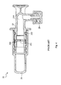
Figure 6 schematically represents a cross section of a connector according to the invention in a disconnected configuration; -
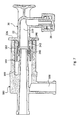
Figure 7 schematically represents a cross section of the connector offigure 6 connected to the hemofiltration machine; -
Figure 8 represents an exploded lateral view of the connector offigure 4 ; -
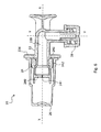
Figure 9 represents an exploded lateral view of the connector offigure 6 ; -
Figures 10 and 11 schematically represent two views of a detail of the connector according to the invention; -
Figure 12 schematically represents a cross section of a connector according to a different embodiment of the invention; -
Figure 13 schematically represents a cross section of a connector according to a different embodiment of the invention. - Referring to the enclosed figures, the
reference 20 indicates a disposable connector suitable for engagement on thesubstitution port 180 of ahemofiltration machine 18. Theconnector 20 comprises: a rigidmain body 22 defining aduct 220; and asoft element 24 fitted on an end of themain body 22. In theconnector 20 according to the invention, thesoft element 24 comprises amembrane 240 occluding theduct 220 and performing a valve function; and aseal portion 242 radially expanding outward of theduct 220. - In the attached figures, same references are used for elements which have same or similar functions, both in the connector according to the invention and in the one according to the prior art.
- The
main body 22 is preferably obtained from polycarbonate (PC), acrylonitrile-butadienestyrene (ABS), unplasticized polyvinyl chloride (uPVC) or some other rigid material suitable for medical use. Thesoft element 24 is preferably obtained from silicone, thermoplastic elastomer (TPE) or some other soft material suitable for medical use. - According to the embodiments shown in the attached
figures 6 ,7 ,9 and12 , theconnector 20 according to the invention is, as a whole, L-shaped. Specifically,duct 220 defined by themain body 22 is L-shaped, having a main axis X and a secondary axis Y, see in particularfigure 6 . Conversely, according to the embodiment shown in the attachedfigure 13 , theconnector 20 according to the invention has a straight development. Specifically,duct 220 defined by themain body 22 has a straight development, having one axis X only. In the following description reference will be made principally to axis X. Consequently, except in case of explicit contrary indication, the term "axial" refers to the direction of a straight line parallel to axis X, the term "radial" refers to the direction of a half-line having its origin on axis X and perpendicular thereto, the term "circumferential" refers to the direction of a circumference having its centre on axis X and laying on a plane perpendicular thereto. - As can be noticed in
figures 2 and 3 , theport 180 of themachine 18 comprises aninner cone 184 and a coaxialouter sleeve 182. Theinner cone 184 defines a supply channel for the substitution liquid, while theouter sleeve 182 defines a protectedinterspace 188 around theinner cone 184. Theouter sleeve 182 further defines adrain channel 186 which is used during the preparatory step for the hemofiltration treatment. Such step is schematically shown infigure 3 where theport 18 is closed by a proper plug. In such condition the substitution liquid coming from themachine 18 is forced to circulate between the outer wall of theinner cone 184 and the inner wall of theouter sleeve 182, and then to flow out through thedrain channel 186. Such circulation allows an accurate washing of theport 18, so as to assure hygiene of the connection. - According to some embodiments of the
disposable connector 20, themembrane 240 is suitable for alternatively assuming a closed configuration or an open configuration. In particular,membrane 240 preferably assumes the closed configuration in a spontaneous manner, or at rest, i.e. in absence of any force directly acting upon it. See in this regardfigure 6 whereinconnector 20 is shown isolated, disengaged from themachine 18. - Conversely,
membrane 240 assumes the open configuration after engagement of theconnector 20 on themachine 18, in particular because of the specific conformation of theport 180 on whichconnector 20 is engaged. See in this regardfigure 7 whereinconnector 20 is shown engaged withport 180; it can be noticed that theinner cone 184 pushes themembrane 240, forcing it to the open configuration. Insuch condition duct 220 ofconnector 20 becomes an extension of the supply channel defined by theinner cone 184. Moreover, in the open configuration, themembrane 240 adheres on the outer wall of theinner cone 184, thus sealing the supply channel from theinterspace 188. A successive disengagement of theconnector 20 from theport 180, removing all the forces acting on themembrane 240, entails that the latter spontaneously assumes back its closed configuration, thus closingduct 220. - According to some embodiments of the invention, e.g. the one shown in
figures 6 ,7 ,9 and13 , themembrane 240 comprises a simplediametrical slot 241. According to other embodiments of the invention, e.g. the one shown infigures 10, 11 and 12 , themembrane 240 comprises a Y-shapedslot 241, i.e. a slot formed of three cuts extending radially from the center of the membrane and spaced by 120° one from the other. - As disclosed above, the
soft element 24 comprises also aseal portion 242, intended to cooperate with theport 180 of themachine 18. In particular, theseal portion 242 is intended to make contact with the inner wall of theouter sleeve 182 so as to seal theinterspace 188 from the outer environment. Engagement betweenconnector 20 andport 180 of themachine 18 entails a slight interference between theseal portion 242 and the inner wall of theouter sleeve 182. As can be noticed infigures 9 and11 , wherein theseal portion 242 is free from any contact, theseal portion 242 radially extends outward and has a substantially semicircular cross section. On the contrary infigure 7 , wherein theseal portion 242 is constricted by the inner wall of theouter sleeve 182, theseal portion 242 has a smaller radial extension and a squashed cross section. - According to the embodiments shown in the attached figures, see in particular
figure 9 , themain body 22 comprises an undercut 224 and anaxial shoulder 226 which radially extends outward. The undercut 224 is placed near the end of themain body 22 upon which thesoft element 24 is fitted. Complementarily, thesoft element 24 comprises aradial step 244 which protrudes inward. When thesoft element 24 is forcedly fitted on the end of themain body 22, theaxial end 246 of thesoft element 24 contacts theshoulder 226 and theradial step 244 engages the undercut 224. In such a manner a shape coupling is established between thesoft element 24 and themain body 22. - The shape coupling assures that the
connector 20 remains firmly assembled during its use. According to some embodiments, such coupling is further strengthened by the specific shape of thesoft element 24, or by the finish of the contact surfaces, or by both of them. - In particular, the coupling can be strengthened by the reciprocal positions of the
radial step 244 and of theseal portion 242 with respect to theaxial end 246. As can be noticed infigure 11 , the distance D between theradial step 244 and theaxial end 246 is longer than or equal to the distance d between theseal portion 242 and theaxial end 246. When theconnector 20 is engaged on theport 180, the specific relationship between D and d allows to exploit the radial pressure exerted by theouter sleeve 182 on theseal portion 242 in order to prevent theradial step 244 from any possible disengagement from the undercut 224 due to its deformation. - The coupling between the
main body 22 and thesoft element 24 can also be strengthened by the finish of the respective surfaces which contact each other. In particular, a very smooth surface finish entails a strong adhesion between the two surfaces. Accordingly, thecontact zone 228 of the main body 22 (seefigure 9 ) and thecontact zone 248 of the soft element 24 (seefigure 11 ) have very smooth surfaces, i.e. polished or lapped surfaces. As the skilled person will appreciate, since both themain body 22 and thesoft element 24 are made of plastic materials, polishing and/or lapping treatments are actually carried out on the respective areas of the moulds, rather than on each single plastic piece. - According to some embodiments,
connector 20 further comprises one or two caps referenced to with 26 and 28 respectively. Such caps, which are suitable for plugging the ends of theduct 220, are intended to be removed before use.Figure 6 shows theconnector 20 with bothcaps Figure 7 shows thesame connector 20 offigure 6 engaged on theport 180 and still having itscap 28 on.Figure 12 shows a different embodiment of theconnector 20 wherein only cap 26 is provided. Accordingly the other end ofduct 220 is open and, in particular, is suitable for receiving a delivery tube to be glued therein. - In view of the above description, the skilled person will easily appreciate that the present invention overcomes most of the drawbacks pointed out with respect to the prior art. In particular, the present invention provides a disposable connector having a simple structure, i.e. a disposable connector made of fewer components with respect to the known one. This can be further appreciated by comparison of
figure 9 , showing an exploded view of the connector according to the invention, withfigure 8 , showing an exploded view of the connector according to the prior art. Accordingly, the present invention reduces the production and assembly costs of the disposable connector, as a matter of fact, assembly of the connector according to the invention simply requires to fit thesoft element 24 on themain body 22. The person skilled in the art can bring modifications and/or replacements of described element with equivalent elements to the embodiments of the connector according to the invention described above, in order to satisfy specific requirements, without for this reason departing from the scope of the attached claims.
Claims (15)
- Connector (20) suitable for engagement on a substitution port (180) of a machine (18) for carrying out a hemofiltration or a hemodiafiltration treatment of a patient's blood, the connector (20) comprising:- a rigid main body (22) defining a duct (220); and- a soft element (24) fitted on an end of the main body (22);wherein said soft element (24) comprises a membrane (240) occluding the duct (220) and performing a valve function; and a seal portion (242) radially expanding outward of the duct (220).
- Connector (20) according to claim 1, characterized by being, as a whole, L-shaped and wherein the duct (220) defined by the main body (22) is also L-shaped.
- Connector (20) according to claim 1 or 2, wherein the substitution port (180) of the machine (18) comprises an inner cone (184) defining a supply channel for the substitution liquid, and a coaxial outer sleeve (182) defining a protected interspace (188) around the inner cone (184).
- Connector (20) according to any one of the preceding claims, wherein the membrane (240) is suitable for alternatively assuming a closed configuration or an open configuration, and wherein the membrane (240) assumes the closed configuration at rest, i.e. in absence of any force directly acting upon it.
- Connector (20) according to claim 4, wherein the membrane (240) assumes the open configuration after engagement of the connector (20) on the port (180), due to the inner cone (184) forcing it to the open configuration.
- Connector (20) according to any one of the preceding claims, wherein, in the open configuration, the membrane (240) adheres on the outer wall of the inner cone (184), thus sealing the duct (220) from the interspace (188).
- Connector (20) according to any one of the preceding claims, wherein the membrane (240) comprises a diametrical slot (241).
- Connector (20) according to any claim 1 to 6, wherein the membrane (240) comprises a Y-shaped slot (241).
- Connector (20) according to any one of the preceding claims, wherein the seal portion (242) is intended to make contact with the inner wall of the outer sleeve (182) of the port (180) so as to seal the interspace (188) from the outer environment.
- Connector (20) according to any one of the preceding claims, wherein:- the main body (22) comprises an undercut (224) near the end and an axial shoulder (226) radially extending outward;- the soft element (24) comprises an axial end and a radial step (244) protruding inward; andwhen the soft element (24) is forcedly fitted on the end of the main body (22), the axial end (246) of the soft element (24) contacts the shoulder (226) and the radial step (244) engages the undercut (224), thus a shape coupling is established between the soft element (24) and the main body (22).
- Connector (20) according to the preceding claim, wherein in the soft element (24) the distance D between the radial step (244) and the axial end (246) is longer than or equal to the distance d between the seal portion (242) and the axial end (246).
- Connector (20) according to any one of the preceding claims, wherein the contact zone (228) of the main body (22) and the contact zone (248) of the soft element (24) have polished or lapped surfaces.
- Connector (20) according to any one of the preceding claims, further comprising two caps (26, 28) suitable for plugging the ends of the duct (220) and intended to be removed before use.
- Connector (20) according to any claim 1 to 9, further comprising a cap (26) suitable for plugging an end of the duct (220) and intended to be removed before use; and wherein the other end of duct (220) is open and suitable for receiving a delivery tube to be glued therein.
- Assembly comprising a connector (20) according to any one of the preceding claims engaged on a substitution port (180) of a machine (18) for carrying out a hemofiltration or a hemodiafiltration treatment of a patient's blood.
Priority Applications (1)
| Application Number | Priority Date | Filing Date | Title |
|---|---|---|---|
| EP24208164.4A EP4470596A3 (en) | 2010-07-06 | 2011-06-21 | Disposable connector for hemofiltration |
Applications Claiming Priority (3)
| Application Number | Priority Date | Filing Date | Title |
|---|---|---|---|
| EP20100168559 EP2404637A1 (en) | 2010-07-06 | 2010-07-06 | Disposable connector for hemofiltration |
| PCT/EP2011/060314 WO2012004123A1 (en) | 2010-07-06 | 2011-06-21 | Disposable connector for hemofiltration |
| EP11726435.8A EP2590707B1 (en) | 2010-07-06 | 2011-06-21 | Disposable connector for hemofiltration |
Related Parent Applications (2)
| Application Number | Title | Priority Date | Filing Date |
|---|---|---|---|
| EP11726435.8A Division EP2590707B1 (en) | 2010-07-06 | 2011-06-21 | Disposable connector for hemofiltration |
| EP11726435.8A Division-Into EP2590707B1 (en) | 2010-07-06 | 2011-06-21 | Disposable connector for hemofiltration |
Related Child Applications (1)
| Application Number | Title | Priority Date | Filing Date |
|---|---|---|---|
| EP24208164.4A Division EP4470596A3 (en) | 2010-07-06 | 2011-06-21 | Disposable connector for hemofiltration |
Publications (3)
| Publication Number | Publication Date |
|---|---|
| EP2962722A1 true EP2962722A1 (en) | 2016-01-06 |
| EP2962722C0 EP2962722C0 (en) | 2024-10-23 |
| EP2962722B1 EP2962722B1 (en) | 2024-10-23 |
Family
ID=43243685
Family Applications (4)
| Application Number | Title | Priority Date | Filing Date |
|---|---|---|---|
| EP20100168559 Withdrawn EP2404637A1 (en) | 2010-07-06 | 2010-07-06 | Disposable connector for hemofiltration |
| EP15177186.2A Active EP2962722B1 (en) | 2010-07-06 | 2011-06-21 | Disposable connector for hemofiltration |
| EP11726435.8A Active EP2590707B1 (en) | 2010-07-06 | 2011-06-21 | Disposable connector for hemofiltration |
| EP24208164.4A Pending EP4470596A3 (en) | 2010-07-06 | 2011-06-21 | Disposable connector for hemofiltration |
Family Applications Before (1)
| Application Number | Title | Priority Date | Filing Date |
|---|---|---|---|
| EP20100168559 Withdrawn EP2404637A1 (en) | 2010-07-06 | 2010-07-06 | Disposable connector for hemofiltration |
Family Applications After (2)
| Application Number | Title | Priority Date | Filing Date |
|---|---|---|---|
| EP11726435.8A Active EP2590707B1 (en) | 2010-07-06 | 2011-06-21 | Disposable connector for hemofiltration |
| EP24208164.4A Pending EP4470596A3 (en) | 2010-07-06 | 2011-06-21 | Disposable connector for hemofiltration |
Country Status (15)
| Country | Link |
|---|---|
| US (2) | US9352139B2 (en) |
| EP (4) | EP2404637A1 (en) |
| JP (1) | JP5901626B2 (en) |
| CN (1) | CN102958559B (en) |
| CY (1) | CY1117866T1 (en) |
| DE (1) | DE202011110793U1 (en) |
| DK (1) | DK2590707T3 (en) |
| ES (2) | ES2585629T3 (en) |
| HR (1) | HRP20160927T1 (en) |
| HU (1) | HUE029274T2 (en) |
| PL (1) | PL2590707T3 (en) |
| PT (1) | PT2590707T (en) |
| RS (1) | RS54969B1 (en) |
| SI (1) | SI2590707T1 (en) |
| WO (1) | WO2012004123A1 (en) |
Families Citing this family (6)
| Publication number | Priority date | Publication date | Assignee | Title |
|---|---|---|---|---|
| US9545472B2 (en) * | 2012-03-02 | 2017-01-17 | Medtronic, Inc. | Extracorporeal blood circuit reservoir with angled venous inlet luer port |
| TWI889914B (en) * | 2020-10-07 | 2025-07-11 | 德商費森尤斯醫療護理德國有限責任公司 | Disposable and system with a port |
| EP3991764B1 (en) | 2020-10-27 | 2024-03-06 | Bellco S.r.l. | Flowmeter for proportioning water in dialysis system |
| US12318528B2 (en) | 2020-10-30 | 2025-06-03 | Mozarc Medical Us Llc | Variable orifice fistula graft |
| ES3007240T3 (en) | 2020-10-30 | 2025-03-19 | Bellco Srl | Dialysis cassette with pump features |
| EP4008376A1 (en) | 2020-12-03 | 2022-06-08 | Medtronic, Inc. | Flexible tube routing accessory for peritoneal dialysis system |
Citations (8)
| Publication number | Priority date | Publication date | Assignee | Title |
|---|---|---|---|---|
| CA1191413A (en) * | 1981-05-28 | 1985-08-06 | William J. O'neill | Removable hemostasis valve |
| US5501426A (en) * | 1992-06-04 | 1996-03-26 | Vernay Laboratories, Inc. | Medical coupling site valve body |
| EP1181946A1 (en) * | 2000-08-04 | 2002-02-27 | Alan David Mogg | Catheter adapter |
| US20030158539A1 (en) * | 2002-02-19 | 2003-08-21 | Laddvanh Bouphavichith | Low profile adaptor for use with a medical catheter |
| US20080093571A1 (en) * | 2006-10-23 | 2008-04-24 | Baxter International Inc. | Luer activated device with minimal fluid displacement |
| WO2008150781A1 (en) * | 2007-06-05 | 2008-12-11 | Dsu Medical Corporation | Fluid flow connector permitting forceful lateral separation |
| JP2009006051A (en) * | 2007-06-29 | 2009-01-15 | Goodman Co Ltd | Medical connector |
| EP2059279A1 (en) | 2006-09-07 | 2009-05-20 | Fresenius Medical Care Deutschland GmbH | Blood processing device and method for purging a set of blood lines on a blood processing device |
Family Cites Families (3)
| Publication number | Priority date | Publication date | Assignee | Title |
|---|---|---|---|---|
| JPS59155255A (en) * | 1983-02-23 | 1984-09-04 | テルモ株式会社 | Connector with valve body |
| CH671159A5 (en) * | 1986-06-20 | 1989-08-15 | Contempo Products | |
| US5957898A (en) * | 1997-05-20 | 1999-09-28 | Baxter International Inc. | Needleless connector |
-
2010
- 2010-07-06 EP EP20100168559 patent/EP2404637A1/en not_active Withdrawn
-
2011
- 2011-06-21 US US13/808,683 patent/US9352139B2/en active Active
- 2011-06-21 PL PL11726435.8T patent/PL2590707T3/en unknown
- 2011-06-21 CN CN201180033283.4A patent/CN102958559B/en active Active
- 2011-06-21 HR HRP20160927TT patent/HRP20160927T1/en unknown
- 2011-06-21 PT PT117264358T patent/PT2590707T/en unknown
- 2011-06-21 DE DE202011110793.4U patent/DE202011110793U1/en not_active Expired - Lifetime
- 2011-06-21 EP EP15177186.2A patent/EP2962722B1/en active Active
- 2011-06-21 ES ES11726435.8T patent/ES2585629T3/en active Active
- 2011-06-21 HU HUE11726435A patent/HUE029274T2/en unknown
- 2011-06-21 DK DK11726435.8T patent/DK2590707T3/en active
- 2011-06-21 RS RS20160566A patent/RS54969B1/en unknown
- 2011-06-21 EP EP11726435.8A patent/EP2590707B1/en active Active
- 2011-06-21 JP JP2013517168A patent/JP5901626B2/en active Active
- 2011-06-21 ES ES15177186T patent/ES3005337T3/en active Active
- 2011-06-21 EP EP24208164.4A patent/EP4470596A3/en active Pending
- 2011-06-21 WO PCT/EP2011/060314 patent/WO2012004123A1/en not_active Ceased
- 2011-06-21 SI SI201130908A patent/SI2590707T1/en unknown
-
2016
- 2016-03-30 US US15/084,520 patent/US10279158B2/en active Active
- 2016-08-02 CY CY20161100758T patent/CY1117866T1/en unknown
Patent Citations (8)
| Publication number | Priority date | Publication date | Assignee | Title |
|---|---|---|---|---|
| CA1191413A (en) * | 1981-05-28 | 1985-08-06 | William J. O'neill | Removable hemostasis valve |
| US5501426A (en) * | 1992-06-04 | 1996-03-26 | Vernay Laboratories, Inc. | Medical coupling site valve body |
| EP1181946A1 (en) * | 2000-08-04 | 2002-02-27 | Alan David Mogg | Catheter adapter |
| US20030158539A1 (en) * | 2002-02-19 | 2003-08-21 | Laddvanh Bouphavichith | Low profile adaptor for use with a medical catheter |
| EP2059279A1 (en) | 2006-09-07 | 2009-05-20 | Fresenius Medical Care Deutschland GmbH | Blood processing device and method for purging a set of blood lines on a blood processing device |
| US20080093571A1 (en) * | 2006-10-23 | 2008-04-24 | Baxter International Inc. | Luer activated device with minimal fluid displacement |
| WO2008150781A1 (en) * | 2007-06-05 | 2008-12-11 | Dsu Medical Corporation | Fluid flow connector permitting forceful lateral separation |
| JP2009006051A (en) * | 2007-06-29 | 2009-01-15 | Goodman Co Ltd | Medical connector |
Also Published As
| Publication number | Publication date |
|---|---|
| SI2590707T1 (en) | 2016-09-30 |
| JP2013530762A (en) | 2013-08-01 |
| HRP20160927T1 (en) | 2016-10-07 |
| EP2590707A1 (en) | 2013-05-15 |
| EP2962722C0 (en) | 2024-10-23 |
| ES3005337T3 (en) | 2025-03-14 |
| RS54969B1 (en) | 2016-11-30 |
| CY1117866T1 (en) | 2017-05-17 |
| EP4470596A3 (en) | 2025-03-12 |
| US10279158B2 (en) | 2019-05-07 |
| US20160271383A1 (en) | 2016-09-22 |
| EP2404637A1 (en) | 2012-01-11 |
| CN102958559B (en) | 2017-05-24 |
| EP2962722B1 (en) | 2024-10-23 |
| ES2585629T3 (en) | 2016-10-07 |
| PT2590707T (en) | 2016-08-17 |
| WO2012004123A1 (en) | 2012-01-12 |
| DK2590707T3 (en) | 2016-08-01 |
| PL2590707T3 (en) | 2016-11-30 |
| DE202011110793U1 (en) | 2016-05-25 |
| CN102958559A (en) | 2013-03-06 |
| US20130112301A1 (en) | 2013-05-09 |
| JP5901626B2 (en) | 2016-04-13 |
| US9352139B2 (en) | 2016-05-31 |
| EP4470596A2 (en) | 2024-12-04 |
| HUE029274T2 (en) | 2017-02-28 |
| EP2590707B1 (en) | 2016-05-04 |
Similar Documents
| Publication | Publication Date | Title |
|---|---|---|
| US10279158B2 (en) | Disposable connector for hemofiltration | |
| JP5891179B2 (en) | A set of easy-to-clean connectors for liquid circuits | |
| US10359139B2 (en) | Connector | |
| CA2848530C (en) | Collar connector | |
| JP4286073B2 (en) | Coupler for dialyzer connection | |
| JP2013066794A (en) | Safety connector assembly | |
| EP2207586B1 (en) | Medical connector able to connect specific medical tube and input port. | |
| CN109803716A (en) | Medical fluid pipe connector | |
| JP2015188571A (en) | Cap for indwelling needle, extracorporeal circulation indwelling needle with cap, blood circuit, and priming method of blood circuit | |
| US12397145B2 (en) | Self-sealing fluid connectors | |
| CN215608036U (en) | A negative pressure tee joint that can be connected in series | |
| WO2008035422A1 (en) | Joint for medical tools and medical instrument |
Legal Events
| Date | Code | Title | Description |
|---|---|---|---|
| PUAI | Public reference made under article 153(3) epc to a published international application that has entered the european phase |
Free format text: ORIGINAL CODE: 0009012 |
|
| AC | Divisional application: reference to earlier application |
Ref document number: 2590707 Country of ref document: EP Kind code of ref document: P |
|
| AK | Designated contracting states |
Kind code of ref document: A1 Designated state(s): AL AT BE BG CH CY CZ DE DK EE ES FI FR GB GR HR HU IE IS IT LI LT LU LV MC MK MT NL NO PL PT RO RS SE SI SK SM TR |
|
| 17P | Request for examination filed |
Effective date: 20160704 |
|
| RBV | Designated contracting states (corrected) |
Designated state(s): AL AT BE BG CH CY CZ DE DK EE ES FI FR GB GR HR HU IE IS IT LI LT LU LV MC MK MT NL NO PL PT RO RS SE SI SK SM TR |
|
| STAA | Information on the status of an ep patent application or granted ep patent |
Free format text: STATUS: EXAMINATION IS IN PROGRESS |
|
| 17Q | First examination report despatched |
Effective date: 20180711 |
|
| GRAP | Despatch of communication of intention to grant a patent |
Free format text: ORIGINAL CODE: EPIDOSNIGR1 |
|
| STAA | Information on the status of an ep patent application or granted ep patent |
Free format text: STATUS: GRANT OF PATENT IS INTENDED |
|
| RIC1 | Information provided on ipc code assigned before grant |
Ipc: A61M 39/10 20060101ALI20240531BHEP Ipc: A61M 39/06 20060101AFI20240531BHEP |
|
| INTG | Intention to grant announced |
Effective date: 20240628 |
|
| GRAS | Grant fee paid |
Free format text: ORIGINAL CODE: EPIDOSNIGR3 |
|
| GRAA | (expected) grant |
Free format text: ORIGINAL CODE: 0009210 |
|
| STAA | Information on the status of an ep patent application or granted ep patent |
Free format text: STATUS: THE PATENT HAS BEEN GRANTED |
|
| AC | Divisional application: reference to earlier application |
Ref document number: 2590707 Country of ref document: EP Kind code of ref document: P |
|
| AK | Designated contracting states |
Kind code of ref document: B1 Designated state(s): AL AT BE BG CH CY CZ DE DK EE ES FI FR GB GR HR HU IE IS IT LI LT LU LV MC MK MT NL NO PL PT RO RS SE SI SK SM TR |
|
| P01 | Opt-out of the competence of the unified patent court (upc) registered |
Free format text: CASE NUMBER: APP_52144/2024 Effective date: 20240917 |
|
| REG | Reference to a national code |
Ref country code: GB Ref legal event code: FG4D |
|
| REG | Reference to a national code |
Ref country code: CH Ref legal event code: EP |
|
| REG | Reference to a national code |
Ref country code: DE Ref legal event code: R096 Ref document number: 602011075054 Country of ref document: DE |
|
| REG | Reference to a national code |
Ref country code: IE Ref legal event code: FG4D |
|
| U01 | Request for unitary effect filed |
Effective date: 20241121 |
|
| P04 | Withdrawal of opt-out of the competence of the unified patent court (upc) registered |
Free format text: CASE NUMBER: APP_62748/2024 Effective date: 20241125 |
|
| U07 | Unitary effect registered |
Designated state(s): AT BE BG DE DK EE FI FR IT LT LU LV MT NL PT RO SE SI Effective date: 20241127 |
|
| REG | Reference to a national code |
Ref country code: ES Ref legal event code: FG2A Ref document number: 3005337 Country of ref document: ES Kind code of ref document: T3 Effective date: 20250314 |
|
| PG25 | Lapsed in a contracting state [announced via postgrant information from national office to epo] |
Ref country code: IS Free format text: LAPSE BECAUSE OF FAILURE TO SUBMIT A TRANSLATION OF THE DESCRIPTION OR TO PAY THE FEE WITHIN THE PRESCRIBED TIME-LIMIT Effective date: 20250223 Ref country code: HR Free format text: LAPSE BECAUSE OF FAILURE TO SUBMIT A TRANSLATION OF THE DESCRIPTION OR TO PAY THE FEE WITHIN THE PRESCRIBED TIME-LIMIT Effective date: 20241023 |
|
| PG25 | Lapsed in a contracting state [announced via postgrant information from national office to epo] |
Ref country code: NO Free format text: LAPSE BECAUSE OF FAILURE TO SUBMIT A TRANSLATION OF THE DESCRIPTION OR TO PAY THE FEE WITHIN THE PRESCRIBED TIME-LIMIT Effective date: 20250123 |
|
| PG25 | Lapsed in a contracting state [announced via postgrant information from national office to epo] |
Ref country code: GR Free format text: LAPSE BECAUSE OF FAILURE TO SUBMIT A TRANSLATION OF THE DESCRIPTION OR TO PAY THE FEE WITHIN THE PRESCRIBED TIME-LIMIT Effective date: 20250124 |
|
| PG25 | Lapsed in a contracting state [announced via postgrant information from national office to epo] |
Ref country code: PL Free format text: LAPSE BECAUSE OF FAILURE TO SUBMIT A TRANSLATION OF THE DESCRIPTION OR TO PAY THE FEE WITHIN THE PRESCRIBED TIME-LIMIT Effective date: 20241023 |
|
| PG25 | Lapsed in a contracting state [announced via postgrant information from national office to epo] |
Ref country code: RS Free format text: LAPSE BECAUSE OF FAILURE TO SUBMIT A TRANSLATION OF THE DESCRIPTION OR TO PAY THE FEE WITHIN THE PRESCRIBED TIME-LIMIT Effective date: 20250123 |
|
| PG25 | Lapsed in a contracting state [announced via postgrant information from national office to epo] |
Ref country code: SM Free format text: LAPSE BECAUSE OF FAILURE TO SUBMIT A TRANSLATION OF THE DESCRIPTION OR TO PAY THE FEE WITHIN THE PRESCRIBED TIME-LIMIT Effective date: 20241023 |
|
| PG25 | Lapsed in a contracting state [announced via postgrant information from national office to epo] |
Ref country code: SK Free format text: LAPSE BECAUSE OF FAILURE TO SUBMIT A TRANSLATION OF THE DESCRIPTION OR TO PAY THE FEE WITHIN THE PRESCRIBED TIME-LIMIT Effective date: 20241023 |
|
| PG25 | Lapsed in a contracting state [announced via postgrant information from national office to epo] |
Ref country code: CZ Free format text: LAPSE BECAUSE OF FAILURE TO SUBMIT A TRANSLATION OF THE DESCRIPTION OR TO PAY THE FEE WITHIN THE PRESCRIBED TIME-LIMIT Effective date: 20241023 |
|
| PLBE | No opposition filed within time limit |
Free format text: ORIGINAL CODE: 0009261 |
|
| STAA | Information on the status of an ep patent application or granted ep patent |
Free format text: STATUS: NO OPPOSITION FILED WITHIN TIME LIMIT |
|
| U21 | Renewal fee for the european patent with unitary effect paid with additional fee |
Year of fee payment: 15 Effective date: 20250812 |
|
| 26N | No opposition filed |
Effective date: 20250724 |
|
| PGFP | Annual fee paid to national office [announced via postgrant information from national office to epo] |
Ref country code: ES Payment date: 20250701 Year of fee payment: 15 |
|
| U1H | Name or address of the proprietor changed after the registration of the unitary effect |
Owner name: FRESENIUS MEDICAL CARE DEUTSCHLAND GMBH; DE |
|
| REG | Reference to a national code |
Ref country code: CH Ref legal event code: H13 Free format text: ST27 STATUS EVENT CODE: U-0-0-H10-H13 (AS PROVIDED BY THE NATIONAL OFFICE) Effective date: 20260127 |
|
| PG25 | Lapsed in a contracting state [announced via postgrant information from national office to epo] |
Ref country code: MC Free format text: LAPSE BECAUSE OF FAILURE TO SUBMIT A TRANSLATION OF THE DESCRIPTION OR TO PAY THE FEE WITHIN THE PRESCRIBED TIME-LIMIT Effective date: 20241023 |
|
| PG25 | Lapsed in a contracting state [announced via postgrant information from national office to epo] |
Ref country code: IE Free format text: LAPSE BECAUSE OF NON-PAYMENT OF DUE FEES Effective date: 20250621 |
|
| PG25 | Lapsed in a contracting state [announced via postgrant information from national office to epo] |
Ref country code: CH Free format text: LAPSE BECAUSE OF NON-PAYMENT OF DUE FEES Effective date: 20250630 |
|
| U20 | Renewal fee for the european patent with unitary effect paid |
Year of fee payment: 16 Effective date: 20260520 |
|
| PGFP | Annual fee paid to national office [announced via postgrant information from national office to epo] |
Ref country code: GB Payment date: 20260520 Year of fee payment: 16 |
|
| PG25 | Lapsed in a contracting state [announced via postgrant information from national office to epo] |
Ref country code: CY Free format text: LAPSE BECAUSE OF FAILURE TO SUBMIT A TRANSLATION OF THE DESCRIPTION OR TO PAY THE FEE WITHIN THE PRESCRIBED TIME-LIMIT Effective date: 20241023 |