EP2962618A1 - Forward/backward movement assistance tool for endoscopic treatment instrument - Google Patents
Forward/backward movement assistance tool for endoscopic treatment instrument Download PDFInfo
- Publication number
- EP2962618A1 EP2962618A1 EP13876380.0A EP13876380A EP2962618A1 EP 2962618 A1 EP2962618 A1 EP 2962618A1 EP 13876380 A EP13876380 A EP 13876380A EP 2962618 A1 EP2962618 A1 EP 2962618A1
- Authority
- EP
- European Patent Office
- Prior art keywords
- treatment instrument
- central axis
- tubular member
- instrument insertion
- advance
- Prior art date
- Legal status (The legal status is an assumption and is not a legal conclusion. Google has not performed a legal analysis and makes no representation as to the accuracy of the status listed.)
- Withdrawn
Links
- 238000012277 endoscopic treatment Methods 0.000 title claims description 24
- 238000011282 treatment Methods 0.000 claims abstract description 313
- 238000003780 insertion Methods 0.000 claims abstract description 230
- 230000037431 insertion Effects 0.000 claims abstract description 230
- 230000007246 mechanism Effects 0.000 claims abstract description 25
- 238000004891 communication Methods 0.000 claims description 19
- 230000001105 regulatory effect Effects 0.000 claims description 14
- 230000002265 prevention Effects 0.000 claims description 8
- 210000000078 claw Anatomy 0.000 claims description 6
- 230000004044 response Effects 0.000 claims description 5
- 230000004048 modification Effects 0.000 description 26
- 238000012986 modification Methods 0.000 description 26
- 238000005452 bending Methods 0.000 description 22
- 210000003811 finger Anatomy 0.000 description 9
- 238000010586 diagram Methods 0.000 description 7
- 230000000694 effects Effects 0.000 description 5
- 238000000034 method Methods 0.000 description 5
- 238000005286 illumination Methods 0.000 description 4
- 230000000994 depressogenic effect Effects 0.000 description 3
- 210000004932 little finger Anatomy 0.000 description 3
- 239000000463 material Substances 0.000 description 3
- 230000006835 compression Effects 0.000 description 2
- 238000007906 compression Methods 0.000 description 2
- 230000003287 optical effect Effects 0.000 description 2
- XLYOFNOQVPJJNP-UHFFFAOYSA-N water Substances O XLYOFNOQVPJJNP-UHFFFAOYSA-N 0.000 description 2
- 239000013013 elastic material Substances 0.000 description 1
- 230000003902 lesion Effects 0.000 description 1
- 239000002184 metal Substances 0.000 description 1
- 238000012856 packing Methods 0.000 description 1
- 239000004810 polytetrafluoroethylene Substances 0.000 description 1
- 229920001343 polytetrafluoroethylene Polymers 0.000 description 1
- 239000011347 resin Substances 0.000 description 1
- 229920005989 resin Polymers 0.000 description 1
- 210000003813 thumb Anatomy 0.000 description 1
Images








Classifications
-
- A—HUMAN NECESSITIES
- A61—MEDICAL OR VETERINARY SCIENCE; HYGIENE
- A61B—DIAGNOSIS; SURGERY; IDENTIFICATION
- A61B1/00—Instruments for performing medical examinations of the interior of cavities or tubes of the body by visual or photographical inspection, e.g. endoscopes; Illuminating arrangements therefor
- A61B1/00131—Accessories for endoscopes
- A61B1/00133—Drive units for endoscopic tools inserted through or with the endoscope
-
- A—HUMAN NECESSITIES
- A61—MEDICAL OR VETERINARY SCIENCE; HYGIENE
- A61B—DIAGNOSIS; SURGERY; IDENTIFICATION
- A61B1/00—Instruments for performing medical examinations of the interior of cavities or tubes of the body by visual or photographical inspection, e.g. endoscopes; Illuminating arrangements therefor
- A61B1/00112—Connection or coupling means
- A61B1/00121—Connectors, fasteners and adapters, e.g. on the endoscope handle
- A61B1/00128—Connectors, fasteners and adapters, e.g. on the endoscope handle mechanical, e.g. for tubes or pipes
-
- A—HUMAN NECESSITIES
- A61—MEDICAL OR VETERINARY SCIENCE; HYGIENE
- A61B—DIAGNOSIS; SURGERY; IDENTIFICATION
- A61B1/00—Instruments for performing medical examinations of the interior of cavities or tubes of the body by visual or photographical inspection, e.g. endoscopes; Illuminating arrangements therefor
- A61B1/012—Instruments for performing medical examinations of the interior of cavities or tubes of the body by visual or photographical inspection, e.g. endoscopes; Illuminating arrangements therefor characterised by internal passages or accessories therefor
- A61B1/018—Instruments for performing medical examinations of the interior of cavities or tubes of the body by visual or photographical inspection, e.g. endoscopes; Illuminating arrangements therefor characterised by internal passages or accessories therefor for receiving instruments
-
- A—HUMAN NECESSITIES
- A61—MEDICAL OR VETERINARY SCIENCE; HYGIENE
- A61B—DIAGNOSIS; SURGERY; IDENTIFICATION
- A61B17/00—Surgical instruments, devices or methods
- A61B17/00234—Surgical instruments, devices or methods for minimally invasive surgery
-
- A—HUMAN NECESSITIES
- A61—MEDICAL OR VETERINARY SCIENCE; HYGIENE
- A61B—DIAGNOSIS; SURGERY; IDENTIFICATION
- A61B17/00—Surgical instruments, devices or methods
- A61B17/00234—Surgical instruments, devices or methods for minimally invasive surgery
- A61B2017/00292—Surgical instruments, devices or methods for minimally invasive surgery mounted on or guided by flexible, e.g. catheter-like, means
- A61B2017/0034—Surgical instruments, devices or methods for minimally invasive surgery mounted on or guided by flexible, e.g. catheter-like, means adapted to be inserted through a working channel of an endoscope
Definitions
- the present invention relates to an advance and retreat assist tool for an endoscopic treatment instrument.
- Patent Literature 1, Patent Literature 2, Patent Literature 3, and Patent Literature 4 have each disclosed an advance and retreat assist tool for an endoscopic treatment instrument which assists a treatment instrument of an endoscope in advancing and retreating.
- Patent Literature 1 Patent Literature 2, Patent Literature 3, and Patent Literature 4
- the advance and retreat assist tool is attached to a treatment instrument insertion hole portion so that the advance and retreat assist tool is provided straight along the central axis direction of the treatment instrument insertion hole portion provided in a treatment instrument insertion portion.
- the central axis direction of the treatment instrument insertion hole portion is slanted relative to the central axis direction of a grasping portion.
- the advance and retreat assist tool is slanted relative to the central axis direction of the grasping portion.
- Patent Literature 1 Patent Literature 2, Patent Literature 3, and Patent Literature 4
- a distal end portion of the advance and retreat assist tool is near the grasping portion, and a proximal end portion of the advance and retreat assist tool is far from the grasping portion.
- the advance and retreat assist tool has an operation portion which is provided at the proximal end portion of the advance and retreat assist tool and which is operated to advance and retreat the treatment instrument. Since the proximal end portion is far from the grasping portion as described above, a finger does not reach the operation portion when the treatment instrument is operated to advance and retreat, which may be a burden to a surgeon. Thus, the advance and retreat assist tool may be difficult to handle and may interfere with smooth one-handed advance and retreat operations. Moreover, the whole endoscope increases in size.
- the advance and retreat assist tool needs to be disposed at a desired position which facilitates use by a surgeon.
- an advance and retreat assist tool for an endoscopic treatment instrument which can be easily operated with one hand, allows smooth one-handed advance and retreat operations, and can rotate around the central axis of a treatment instrument insertion hole portion in accordance with procedures.
- an advance and retreat assist tool for an endoscopic treatment instrument, the advance and retreat assist tool being removably attached to a treatment instrument insertion portion provided in a grasping portion of an endoscope, the advance and retreat assist tool assisting a distal end portion of the treatment instrument in advancing and retreating along a longitudinal axis direction of the treatment instrument, the distal end portion of the treatment instrument being inserted into the endoscope from a treatment instrument insertion hole portion provided in the treatment instrument insertion portion and projecting from a distal end portion of an insertion portion of the endoscope, the advance and retreat assist tool includes a base unit comprising a first hole portion which has a first central axis, and a second hole portion which has a second central axis slanted relative to the first central axis and which is in communication with the first hole portion; an attachment portion which attaches the base unit to the treatment instrument insertion portion so that the first central axis is provided coaxially with the central axis of the treatment instrument insertion hole portion, so that the
- an advance and retreat assist tool for an endoscopic treatment instrument which can be easily operated with one hand, allows smooth one-handed advance and retreat operations, and can rotate around the central axis of a treatment instrument insertion hole portion in accordance with procedures.
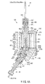
- an attachment portion 400 and a treatment instrument insertion cap 36 are shown in FIG. 1A in a simplified form, some components are not shown for clarity in some of the drawings.
- the advance of a first tubular member 500 means that the first tubular member 500 moves along the direction of a third central axis 500a so that the first tubular member 500 is inserted into a second tubular member 803.
- the retreat of the first tubular member 500 means that the first tubular member 500 moves along the direction of the third central axis 500a so that the first tubular member 500 is removed from the second tubular member 803.
- the advance and retreat of the first tubular member 500 include the advance of the first tubular member 500 and the retreat of the first tubular member 500.
- the advance of a treatment instrument 51 means that the treatment instrument 51 moves so that the treatment instrument 51 moves to the side of a distal hard portion 21 from the side of an operation portion 30 and a distal end portion 51a of the treatment instrument 51 projects outward from the inside of an insertion portion 20 via a distal opening portion 35b in response to the advance of the first tubular member 500.
- the retreat of the treatment instrument 51 means that the treatment instrument 51 moves so that the treatment instrument 51 moves to the side of the operation portion 30 from the side of the distal hard portion 21 and the distal end portion 51a of the treatment instrument 51 is housed in the insertion portion 20 from the outside via the distal opening portion 35b in response to the retreat of the first tubular member 500.
- the advance and retreat of the treatment instrument 51 include the advance of the treatment instrument 51 and the retreat of the treatment instrument 51.
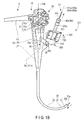
- an endoscopic system 5 has an endoscope 10, the endoscopic treatment instrument (hereinafter, treatment instrument 51), and an advance and retreat assist tool 100 for the treatment instrument 51.
- the endoscope 10 has a hollow and elongated insertion portion 20 to be inserted into, for example, a body cavity, and the operation portion 30 which is coupled to the proximal end portion of the insertion portion 20 and which operates the endoscope 10.
- the insertion portion 20 has the distal hard portion 21, a bending portion 23, and a flexible tubular portion 25 from the distal end portion side of the insertion portion 20 to the proximal end portion side portion of the insertion portion 20.
- the proximal end portion of the distal hard portion 21 is coupled to the distal end portion of the bending portion 23, and the proximal end portion of the bending portion 23 is coupled to the distal end portion of the flexible tubular portion 25.
- the distal hard portion 21 is the distal end portion of the insertion portion 20, and is hard and unbendable.
- the distal hard portion 21 has the distal opening portion 35b, and an unshown observation window included in an unshown observation optical system.
- the distal hard portion 21 also has an unshown pair of illumination windows which are provided across the observation window and which are included in an unshown illumination optical system, and a nozzle which supplies air and water to the observation window.
- the distal opening portion 35b, the observation window, the illumination windows, and the nozzle are provided in a distal end face of the distal hard portion 21.
- the bending portion 23 is bent in a desired direction, for example, in an upward, downward, leftward, or rightward direction by the operation of a later-described bending operation portion 37.
- a later-described bending operation portion 37 When the bending portion 23 is bent, the position and direction of the distal hard portion 21 are changed.
- An observation target is illuminated by unshown illumination light, and the observation target enters into an observation field.
- This observation target is, for example, an affected part or a lesion in a subject (e.g., body cavity).
- the flexible tubular portion 25 has desired flexibility. Therefore, the flexible tubular portion 25 is bent by an external force.
- the flexible tubular portion 25 is a tubular member extending from a later-described body portion 31 in the operation portion 30.
- the operation portion 30 has the body portion 31 from which the flexible tubular portion 25 extends, a grasping portion 33 which is coupled to the proximal end portion of the body portion 31 and which is grasped by a surgeon who operates the endoscope 10, and a universal cord 41 connected to the grasping portion 33.
- the grasping portion 33 has a treatment instrument insertion portion 35, the bending operation portion 37 which is operated to bend the bending portion 23, and a switch portion 39.
- the treatment instrument insertion portion 35 is provided on the distal end portion side of the grasping portion 33.
- the bending operation portion 37 and the switch portion 39 are provided on the proximal end portion side of the grasping portion 33. As shown in FIG. 5A , the grasping portion 33 is grasped by the left hand of the surgeon, and the bending operation portion 37 and the switch portion 39 are operated by the fingers of the left hand.
- the treatment instrument insertion portion 35 branches off from the grasping portion 33.
- the central axis direction of the treatment instrument insertion portion 35 is slanted relative to the direction of a central axis 33a of the grasping portion 33.
- the treatment instrument insertion portion 35 has a treatment instrument insertion hole portion 35a which is provided at the end portion of the treatment instrument insertion portion 35 and which is used to insert the treatment instrument 51 into the endoscope 10.
- the treatment instrument insertion hole portion 35a is coupled to the proximal end portion of an unshown treatment instrument insertion channel.
- the treatment instrument insertion channel is provided inside the insertion portion 20, and provided from the flexible tubular portion 25 to the distal hard portion 21 via the bending portion 23.
- the distal end portion of the treatment instrument insertion channel is in communication with the distal opening portion 35b provided in the distal hard portion 21.
- the treatment instrument insertion hole portion 35a is an insertion hole portion used to insert the treatment instrument 51 into the treatment instrument insertion channel.
- a central axis 35c of the treatment instrument insertion hole portion 35a is provided coaxially with the central axis of the treatment instrument insertion portion 35, and is thus slanted relative to the central axis 33a of the grasping portion 33.
- the direction of the central axis 35c is slanted relative to the direction of the central axis 33a of the grasping portion 33.
- the treatment instrument insertion portion 35 further has a cylindrical treatment instrument insertion cap 36 to be inserted into the treatment instrument insertion hole portion 35a.
- the treatment instrument insertion cap 36 is made of, for example, a metal.
- the central axis of the treatment instrument insertion cap 36 is provided coaxially with the central axis 35c of the treatment instrument insertion hole portion 35a.
- the treatment instrument insertion cap 36 is slanted relative to the grasping portion 33.
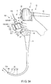
- the treatment instrument 51 is inserted into the treatment instrument insertion channel from the treatment instrument insertion hole portion 35a via the treatment instrument insertion cap 36, and pressed to the side of the distal hard portion 21. As shown in FIG. 1A and FIG. 1B , the treatment instrument 51 is then projected from the distal opening portion 35b.
- the advance and retreat assist tool 100 is attached to the treatment instrument insertion cap 36.
- the treatment instrument insertion cap 36 is brought into communication with a first hole portion 311 of a later-described base member 310.
- the treatment instrument insertion cap 36 has a distal end portion to be inserted into the treatment instrument insertion hole portion 35a, and a proximal end portion which projects outward from the treatment instrument insertion hole portion 35a and which is exposed to the outside.
- the proximal end portion has an edge portion 36c.
- the edge portion 36c is formed as an outer flange, and is folded outward in the diametrical direction of the treatment instrument insertion cap 36.
- the bending operation portion 37 has a horizontal bending operation knob 37a which is operated to horizontally bend the bending portion 23, a vertical bending operation knob 37b which is operated to vertically bend the bending portion 23, and a fixing knob 37c which fixes the position of the bent bending portion 23.
- the switch portion 39 is operated by the hand of the surgeon when the grasping portion 33 is grasped by the surgeon.
- the switch portion 39 is operated during the operation of various functions of the endoscope such as air supply, water supply, suction, and photography.
- the universal cord 41 has an unshown connector which can be attached to and removed from an unshown control apparatus.
- the treatment instrument 51 is formed by, for example, an elongated linear member.
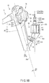
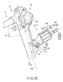
- the advance and retreat assist tool 100 is removably attached to the endoscope 10, in particular, the treatment instrument insertion portion 35. More specifically, as shown in FIG. 1C , FIG. 5B and FIG. 5C , the advance and retreat assist tool 100 is removably attached to the treatment instrument insertion cap 36 which is inserted into the treatment instrument insertion hole portion 35a of the treatment instrument insertion portion 35 so that the advance and retreat assist tool 100 is rotatable around the central axis of the treatment instrument insertion cap 36 ( the central axis 35c of the treatment instrument insertion hole portion 35a ).
- the advance and retreat assist tool 100 assists the treatment instrument 51 in advancing and retreating along the longitudinal axis direction of the treatment instrument 51.
- the treatment instrument 51 is inserted in the endoscope 10 from the treatment instrument insertion hole portion 35a via the treatment instrument insertion cap 36.
- the distal end portion 51a of the treatment instrument 51 can project from the distal opening portion 35b.
- the advance and retreat assist tool 100 has a base unit 300, and the attachment portion 400 which removably attaches the base unit 300 to the treatment instrument insertion portion 35 (the treatment instrument insertion cap 36) so that the base unit 300 is rotatable around the central axis 35c of the treatment instrument insertion hole portion 35a (the treatment instrument insertion cap 36).
- the advance and retreat assist tool 100 further has the first tubular member 500 through which the treatment instrument 51 is inserted and which guides the treatment instrument 51 to the endoscope 10 via the base unit 300, and a fixing portion 600 which fixes the treatment instrument 51 to the first tubular member 500.
- the advance and retreat assist tool 100 further has a rotary portion 700 provided in the first tubular member 500, and an advance and retreat mechanism 800 which advances and retreats the first tubular member 500 by a rotation force of the rotary portion 700.
- the advance and retreat assist tool 100 further has a regulating mechanism 900 which regulates the advance and retreat of the first tubular member 500, and a support unit 950 which supports the first tubular member 500 so that the first tubular member 500 advances and retreats.
- the base unit 300 is removably attached to the treatment instrument insertion cap 36 by the attachment portion 400.
- the base unit 300 is also attached to the treatment instrument insertion cap 36 by the attachment portion 400 rotatably relative to the treatment instrument insertion cap 36 around the central axis of the treatment instrument insertion cap 36.
- the base unit 300 has the base member 310.
- the base member 310 is provided to face the treatment instrument insertion hole portion 35a in the direction of the central axis 35c of the treatment instrument insertion hole portion 35a when the advance and retreat assist tool 100 is attached to the endoscope 10.
- the base member 310 has the first hole portion 311 which has a first central axis 311a, and a second hole portion 313 which has a second central axis 313a slanted relative to the first central axis 311a and which is in communication with the first hole portion 311.
- the first hole portion 311 faces the inside of the treatment instrument insertion cap 36 and the treatment instrument insertion channel when the advance and retreat assist tool 100 is attached to the endoscope 10.
- the first central axis 311a of the first hole portion 311 is provided coaxially with the central axis 35c of the treatment instrument insertion hole portion 35a, and is slanted relative to the central axis 33a of the grasping portion 33.
- the second central axis 313a of the second hole portion 313 is slanted relative to the central axis 35c of the treatment instrument insertion hole portion 35a.
- the first hole portion 311 is in communication with the outside in one end face of the base member 310, and the second hole portion 313 is in communication with the outside in the other end face of the base member 310.
- the first hole portion 311 is depressed in one end face of the base member 310.
- the second hole portion 313 is depressed in the other end face of the base member 310.
- the first hole portion 311 and the second hole portion 313 function as guide hole portions which guide, to the treatment instrument insertion hole portion 35a via the attachment portion 400 and the treatment instrument insertion cap 36, the treatment instrument 51 which is inserted through the first tubular member 500.
- the first hole portion 311 has substantially the same diameter as that of the treatment instrument 51.
- the second hole portion 313 also functions as an insertion hole portion into which the first tubular member 500 is inserted.
- the second hole portion 313 is larger than the first hole portion 311.
- the base member 310 further has a third hole portion 315 which is in communication with the first hole portion 311 and which is larger than the first hole portion 311.
- the central axis of the third hole portion 315 is provided coaxially with the first central axis 311a of the first hole portion 311.
- the third hole portion 315 is in communication with the outside in one end face of the base member 310, and is depressed in one end face of the base member 310.
- the third hole portion 315 is provided outside the first hole portion 311, in particular, provided on the side of the treatment instrument insertion cap 36.
- one end portion of the first hole portion 311 is in communication with the second hole portion 313, and the other end portion of the first hole portion 311 is in communication with the third hole portion 315.
- a support portion 430 of the attachment portion 400 is screwed into the third hole portion 315.
- the attachment portion 400 removably attaches the base unit 300 to the treatment instrument insertion portion 35 (the treatment instrument insertion cap 36) so that the first central axis 311a is provided coaxially with the central axis 35c of the treatment instrument insertion hole portion 35a, so that the first hole portion 311 faces the treatment instrument insertion hole portion 35a, and so that the base member 310 of the base unit 300 is rotatable around the central axis 35c of the treatment instrument insertion hole portion 35a (the central axis of the treatment instrument insertion cap 36).
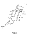
- the attachment portion 400 has a cylindrical body portion 410 which is removably attached to the treatment instrument insertion cap 36 so that the body portion 410 is rotatable around the central axis 35c of the treatment instrument insertion hole portion 35a, and the cylindrical support portion 430 which is removably attached to the body portion 410 and which supports the base member 310.
- the body portion 410 is independent of the support portion 430.
- the body portion 410 and the support portion 430 are comprised of an elastic material such as a resin or rubber.
- the body portion 410 has a body thread groove portion 411 formed in the inner circumferential surface of the body portion 410.
- the body thread groove portion 411 is provided at the proximal end portion of the body portion 410.
- the support portion 430 has a distal end support thread groove portion 431 which is formed in the outer circumferential surface of the support portion 430 and which meshes with the body thread groove portion 411.
- the distal end support thread groove portion 431 is provided at the distal end portion of the support portion 430.
- the support portion 430 is attached to the body portion 410 when the support portion 430 is screwed into the body portion 410 in the central axis direction of the attachment portion 400 as shown in FIG. 2C so that the body thread groove portion 411 and the distal end support thread groove portion 431 mesh with each other while the body portion 410 is attached to the treatment instrument insertion cap 36.
- the body portion 410 and the support portion 430 fasten to each other.
- the body portion 410 and the support portion 430 communicate with the treatment instrument insertion cap 36.
- the edge portion 36c of the treatment instrument insertion cap 36 which is formed as the outer flange is provided between the support portion 430 and a distal end portion of the body portion 410 formed as an inner flange in the direction of the central axis 35c of the treatment instrument insertion hole portion 35a.
- the support portion 430 is attached to the body portion 410 so that the support portion 430 presses the edge portion 36c into the distal end portion of the body portion 410.
- the attachment portion 400 is fixed to the treatment instrument insertion cap 36.
- the advance and retreat assist tool 100 further has an interference prevention member 450 which intervenes between the support portion 430 and the edge portion 36c of the treatment instrument insertion cap 36 in the direction of the central axis 35c of the treatment instrument insertion hole portion 35a and which prevents interference between the support portion 430 and the edge portion 36c.
- the interference prevention member 450 is made of, for example, PTFE. The interference prevention member 450 is in close contact with the support portion 430 and the edge portion 36c of the treatment instrument insertion cap 36.
- the body portion 410 has a cutout portion 413 which is formed by the depression of a part of the edge portion of the body portion 410 in the central axis direction of the body portion 410.
- the cutout portion 413 is provided at the distal end portion of the body portion 410.
- the cutout portion 413 is not provided flush with the body thread groove portion 411, and is provided closer to the side of the treatment instrument insertion hole portion 35a than the body thread groove portion 411.
- the cutout portion 413 is not formed over the entire circumference of the body portion 410 in the circumferential direction of the body portion 410, but is formed in a size smaller than, for example, a semicircle. This cutout portion 413 is in communication with the inside of body portion 410 in the diametrical direction of the body portion 410.
- the distal end portion of the body portion 410 is folded inward as the inner flange.
- the body portion 410 is not attached to the treatment instrument insertion cap 36 by being fitted into the proximal end portion of the treatment instrument insertion cap 36 in the axial direction of the treatment instrument insertion cap 36. As shown in FIG. 2C , the cutout portion 413 functions as a head, and the body portion 410 is pressed into the proximal end portion of the treatment instrument insertion cap 36 from the cutout portion 413 in the diametrical direction of the body portion 410.
- the body portion 410 is pressed into the proximal end portion of the treatment instrument insertion cap 36 from the side surface of the treatment instrument insertion portion 35 via the cutout portion 413 in the diametrical direction of the body portion 410, and is thereby fitted into the proximal end portion of the treatment instrument insertion cap 36, and attached to the proximal end portion of the treatment instrument insertion cap 36.
- the proximal end portion of the treatment instrument insertion cap 36 is fitted into the body portion 410 in the diametrical direction of the body portion 410 via the cutout portion 413.
- the body portion 410 is attached to the proximal end portion of the treatment instrument insertion cap 36, and the proximal end portion of the treatment instrument insertion cap 36 is provided inside the body portion 410.
- the distal end portion of the body portion 410 formed as the inner flange is caught on the edge portion 36c of the treatment instrument insertion cap 36 formed as the outer flange.
- the body portion 410 is rotatable relative to the treatment instrument insertion cap 36 around the central axis 35c of the treatment instrument insertion hole portion 35a.
- the body portion 410 When the body portion 410 is detached from the treatment instrument insertion cap 36, the body portion 410 is pulled relative to the proximal end portion of the treatment instrument insertion cap 36 in the diametrical direction of the body portion 410 via the cutout portion 413 and then detached from the proximal end portion of the treatment instrument insertion cap 36, in reverse order from the above.
- the support portion 430 which supports the base member 310 of the base unit 300, the support portion 430 is attached to the body portion 410 so that the first central axis 311a of the first hole portion 311 is provided coaxially with the central axis 35c of the treatment instrument insertion hole portion 35a and so that the first hole portion 311 faces the treatment instrument insertion hole portion 35a.
- the support portion 430 has a distal end portion which is screwed into the body portion 410, and a proximal end portion which is screwed into the third hole portion 315 and thereby supports the base member 310.
- the proximal end is screwed into the third hole portion 315 so that the support portion 430 communicates with the first hole portion 311.
- the support portion 430 has a watertight member 433 which is provided inside the proximal end portion of the support portion 430 and which keeps the base member 310 and the support portion 430 watertight.
- the watertight member 433 has, for example, a ring-shaped packing.
- the watertight member 433 has a protrusion portion 433a provided in the outer circumferential surface of the watertight member 433.
- the protrusion portion 433a slides on a slide groove 435 formed in the proximal end portion of the support portion 430 when the watertight member 433 is inserted into and removed from the proximal end portion of the support portion 430.
- the protrusion portion 433a is grasped when the watertight member 433 is inserted into and removed from the proximal end portion of the support portion 430, and is provided to position the watertight member 433 in the circumferential direction of the support portion 430.
- the base member 310 further has a base thread groove portion 315a formed in the inner circumferential surface of the third hole portion 315.
- the support portion 430 further has a proximal support thread groove portion 437 which is formed in the outer circumferential surface of the support portion 430 and which meshes with the base thread groove portion 315a.
- the proximal support thread groove portion 437 is provided at the proximal end portion of the support portion 430.
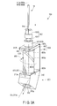
- the support portion 430 is screwed into the third hole portion 315 in the central axis direction of the attachment portion 400 as shown in FIG. 2C , FIG. 4A , and FIG. 4B so that the base thread groove portion 315a and the proximal support thread groove portion 437 mesh with each other, and the support portion 430 is thereby attached to the base member 310.
- the base member 310 and the support portion 430 fasten to each other.
- the support portion 430 communicates with the first hole portion 311.
- the base member 310 is attached to the support portion 430, the support portion 430 is attached to the body portion 410, and the body portion 410 is attached to the treatment instrument insertion cap 36.
- the central axis direction of the treatment instrument insertion portion 35 is slanted relative to the direction of the central axis 33a of the grasping portion 33.
- an angle formed between the direction of the central axis 35c of the treatment instrument insertion hole portion 35a (the direction of the first central axis 311a of the first hole portion 311) and the direction of the central axis 33a of the grasping portion 33 is an angle ⁇ 1.
- the angle ⁇ 1 is invariable even if the advance and retreat assist tool 100 including the attachment portion 400 rotates around the central axis of the treatment instrument insertion cap 36.
- an angle formed between the direction of the second central axis 313a and the direction of the central axis 33a of the grasping portion 33 is an angle ⁇ 2.
- the angle ⁇ 2 is an angle at which the advance and retreat assist tool 100 is slanted closer to the grasping portion 33, a clearance 60 between the grasping portion 33 and the rotary portion 700 is smallest, the distance between the grasping portion 33 and the rotary portion 700 is shortest, and the rotary portion 700 is adjacent to the grasping portion 33.
- the angle ⁇ 2 is an angle which is formed when the rotary portion 700 is operated to advance and retreat the treatment instrument 51 and which allows one hand to grasp the endoscope 10 and advance and retreat the treatment instrument 51 at the same time.
- an angle formed between the direction of the second central axis 313a and the direction of the central axis 33a of the grasping portion 33 is an angle ⁇ 3.
- the angle ⁇ 3 is an angle at which the advance and retreat assist tool 100 is slanted away from the grasping portion 33, the clearance 60 between the grasping portion 33 and the rotary portion 700 is widest, and the distance between the grasping portion 33 and the rotary portion 700 is longest.
- the angle ⁇ 3 is an angle which is formed when the treatment instrument 51 does not need to be operated to advance and retreat and when the rotary portion 700 is not operated and which eliminates the interruption of the grasping by the advance and retreat assist tool 100.
- the attachment portion 400 attached to the treatment instrument insertion cap 36 rotates around the central axis 35c of the treatment instrument insertion hole portion 35a so that the angle ⁇ 1 > the angle ⁇ 2 when the rotary portion 700 is operated and so that the angle ⁇ 3 > the angle ⁇ 1 when the rotary portion 700 is not operated.
- the base member 310 attached to the attachment portion 400 also rotates.
- the first tubular member 500 has the third central axis 500a.
- the first tubular member 500 is provided so that the third central axis 500a is provided along the direction of the second central axis 313a and so that the third central axis 500a is provided coaxially with the second central axis 313a.
- the first tubular member 500 is formed as a cylindrical member into which the treatment instrument 51 is inserted. The treatment instrument 51 is inserted into the first tubular member 500 from a proximal end portion 500c of the first tubular member 500, and is projected from a distal end portion 500b of the first tubular member 500.
- the treatment instrument 51 is directly inserted into the first hole portion 311 when the first tubular member 500 advances.
- the treatment instrument 51 is inserted into the first hole portion 311 via the second hole portion 313 when the first tubular member 500 retreats. That is, the first tubular member 500 functions as a guide member which guides the treatment instrument 51 to the first hole portion 311.
- the first tubular member 500 has the above-mentioned third central axis 500a, and the distal end portion 500b which is inserted into the second hole portion 313 when the first tubular member 500 advances and which is removed from the second hole portion 313 when the first tubular member 500 retreats.
- the first tubular member 500 also has the proximal end portion 500c to which a proximal end portion 51b of the treatment instrument 51 is fixed by the fixing portion 600.
- the first tubular member 500 further has an opening portion 500d which is provided in the circumferential surface of the first tubular member 500 and with which a later-described protrusion portion 801 is engaged.
- the distal end portion 500b is inserted into the second hole portion 313 so that the first tubular member 500 is in communication with the first hole portion 311 when the first tubular member 500 advances.
- the distal end portion 500b is removed from the second hole portion 313 so that the first tubular member 500 faces the first hole portion 311 when the first tubular member 500 retreats.
- the opening portion 500d is provided on the side of the distal end portion 500b so that the opening portion 500d is not inserted into the second hole portion 313 when the distal end portion 500b is inserted into the second hole portion 313.
- the opening portion 500d is always exposed from the second hole portion 313.
- the opening portion 500d is, for example, circular.
- the opening portion 500d is a through-hole portion which passes through the first tubular member 500 in the thickness direction of the first tubular member 500.
- a pair of opening portions 500d are provided with respect to the third central axis 500a.
- the fixing portion 600 is provided at the proximal end portion 500c of the first tubular member 500.
- the fixing portion 600 fixes the proximal end portion 51b of the treatment instrument 51 to the proximal end portion 500c of the first tubular member 500.
- the fixing portion 600 has a cylindrical portion 601 through which the treatment instrument 51 is inserted and which is inserted into the proximal end portion 500c of the first tubular member 500, and a fixing member 605 which is mounted at the end portion of the cylindrical portion 601 and through which the treatment instrument 51 is inserted.
- the fixing portion 600 also has a fastening portion 603 which functions as a cap to cover the cylindrical portion 601 and the fixing member 605 and which fastens the cylindrical portion 601.
- the fastening portion 603 rotates around the axis of the fastening portion 603 and thereby fastens the cylindrical portion 601, and compresses the fixing member 605 by fastening.
- the fixing member 605 comes into close contact with the proximal end portion 51b of the treatment instrument 51 by compression. As a result, the treatment instrument 51 becomes integral with the first tubular member 500 via the fixing portion 600.
- the fixing member 605 is formed by, for example, elastic rubber.
- the rotary portion 700 rotates around the third central axis 500a.
- the rotary portion 700 is formed as a cylindrical member into which the first tubular member 500 is inserted. More specifically, the first tubular member 500 is inserted into the rotary portion 700 so that the central axis of the rotary portion 700 is provided coaxially with the third central axis 500a.
- the rotary portion 700 is rotatable around the second central axis 500a using the first tubular member 500 as a central axis while the first tubular member 500 is inserted in the rotary portion 700. As shown in FIG.
- the rotary portion 700 has a length such that the proximal end portion 500c of the first tubular member 500 projects outside the proximal end portion of the rotary portion 700 along the direction of the third central axis 500a when the distal end portion 500b of the first tubular member 500 is inserted in the second hole portion 313 while the first tubular member 500 is inserted in the rotary portion 700.
- the rotary portion 700 is provided adjacent to the grasping portion 33 when the advance and retreat assist tool 100 is attached to the endoscope 10.
- the rotary portion 700 functions as an operation knob.
- the rotary portion 700 has recess portions 701 provided in the outer circumferential surface of the rotary portion 700.
- the recess portions 701 are provided along the direction of the third central axis 500a.
- the recess portions 701 are adjacent to each other in a direction around the third central axis 500a.
- the inner circumferential surface of the recess 701 is, for example, smoothly semicircular.
- the recess portions 701 are formed as mounting surfaces to mount the fingers of the left hand grasping the grasping portion 33.
- the advance and retreat mechanism 800 intervenes between the rotary portion 700 and the first tubular member 500, the advance and retreat mechanism 800 converts the rotation force of the rotary portion 700 to an advance and retreat force of the first tubular member 500, and the advance and retreat mechanism 800 transmits the advance and retreat force to the first tubular member 500 and thereby advances and retreats the first tubular member 500 along the direction of the third central axis 500a, when the rotary portion 700 rotates.
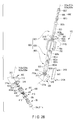
- the advance and retreat mechanism 800 has the protrusion portion 801, the second tubular member 803, and a third tubular member 805. As shown in FIG. 4A and FIG. 4B , the protrusion portion 801, the second tubular member 803, and the third tubular member 805 intervene between the first tubular member 500 and the rotary portion 700 in the diametrical direction of the first tubular member 500.
- the protrusion portion 801 is provided straight along the diametrical direction of the first tubular member 500 so that the protrusion portion 801 passes through a later-described long opening portion 803d and is inserted into a later-described spiral opening portion 805d.
- the protrusion portion 801 is engaged with the opening portion 500d, and is thereby engaged with the circumferential surface of the first tubular member 500.
- the protrusion portion 801 has a diameter such that the protrusion portion 801 abuts on the edge portion of the long opening portion 803d and the edge portion of the spiral opening portion 805d.
- the second tubular member 803 has a fourth central axis 803a, and a distal end portion 803b which is fitted into and thus fixed to the second hole portion 313 so that the fourth central axis 803a is provided along the direction of the second central axis 313a and so that the fourth central axis 803a is provided coaxially with the second central axis 313a.
- the second tubular member 803 further has a proximal end portion 803c, and the long opening portion 803d provided in the circumferential surface of the second tubular member 803 along the direction of the fourth central axis 803a.
- the distal end portion 803b is formed as a fixed end which is fixed to the base member 310 by, for example, a screw portion 213e when the distal end portion 803b is inserted in the second hole portion 313.
- the screw portion 213e is inserted through the side surface of the base member 310, and abuts on the circumferential surface of the distal end portion 803b.
- the proximal end portion 803c is formed as a fixed end which is fixed to the support unit 950 by, for example, a screw portion 213f when the proximal end portion 803c is inserted in the fit hole portion 953c of the support unit 950.
- the screw portion 213f is inserted through the side surface of the support unit 950, and abuts on the circumferential surface of the proximal end portion 803c.
- the second tubular member 803 is prevented from rotating and moving, and is fixed to the base unit 300 and the support unit 950.
- the long opening portion 803d is provided straight from the side of the distal end portion 803b to the side of the proximal end portion 803c.
- the distal end portion of the long opening portion 803d is provided on the side of the distal end portion 803b so that the distal end portion of the long opening portion 803d is not inserted into the second hole portion 313 when the distal end portion 803b is inserted in the second hole portion 313.
- the proximal end portion of the long opening portion 803d is provided on the side of the proximal end portion 803c so that the proximal end portion of the long opening portion 803d is not inserted into the fit hole portion 953c of the support unit 950 when the proximal end portion 803c is inserted in the fit hole portion 953c of the support unit 950. That is, the long opening portion 803d is exposed from the second hole portion 313 and the fit hole portion 953c of the support unit 950.
- the long opening portion 803d has a length slightly greater than the length from one edge portion of the later-described spiral opening portion 805d to the other edge portion in the direction of the fourth central axis 803a.
- One edge portion side of the long opening portion 803d faces one edge portion of the spiral opening portion 805d, and the other edge portion side of the long opening portion 803d faces the other edge portion of the spiral opening portion 805d.
- the long opening portion 803d is substantially equal in length to the rotary portion 700.
- the length of the long opening portion 803d corresponds to the movement amount of the first tubular member 500, and corresponds to the advance and retreat amount of the treatment instrument 51. These are substantially equal in size to each other.
- the maximum value of the length corresponds to the maximum value of the movement amount and the maximum value of the advance and retreat amount. Each of these maximum values corresponds to the size of the part to be treated with the treatment instrument 51, and has a desired value.
- the maximum value is, for example, 30 mm.
- the long opening portion 803d does not pass through the second tubular member 803 in the direction of the fourth central axis 803a.
- the long opening portion 803d passes through the second tubular member 803 in the thickness direction of the second tubular member 803.
- a pair of long opening portions 803d are provided with respect to the fourth central axis 803a.
- Such a second tubular member 803 is formed as a cylindrical member into which the first tubular member 500 is inserted so that part of the long opening portion 803d is in communication with the opening portion 500d and the protrusion portion 801 is inserted through the long opening portion 803d.
- the second tubular member 803 has a length such that the proximal end portion 500c of the first tubular member 500 projects outside the proximal end portion 803c of the second tubular member 803 along the direction of the second central axis 313a when the first tubular member 500 is inserted in the second tubular member 803, the distal end portion 500b of the first tubular member 500 is inserted in the second hole portion 313, and the distal end portion 803b of the second tubular member 803 is fitted in the second hole portion 313.
- the third tubular member 805 has a fifth central axis 805a provided coaxially with the third central axis 500a, and a distal end portion 805b.
- the third tubular member 805 also has a proximal end portion 805c, and the spiral opening portion 805d provided in the circumferential surface of the third tubular member 805 to wind around the fifth central axis 805a.
- the third tubular member 805 is provided so that the distal end portion 805b is not inserted into the second hole portion 313 and the proximal end portion 805c is not inserted into the support unit 950.
- the third tubular member 805 is inserted into the rotary portion 700 so that the third tubular member 805 rotates relative to the second tubular member 803 around the fifth central axis 805a together with the rotary portion 700.
- the third tubular member 805 is fixed to the rotary portion 700 by a screw portion 213g shown in FIG. 2B so that the third tubular member 805 rotates together with the rotary portion 700.
- the third tubular member 805 rotates in the same direction as the rotary portion 700.
- the third tubular member 805 functions as a cylindrical member into which the second tubular member 803 is inserted so that part of the spiral opening portion 805d is in communication with part of the long opening portion 803d and so that the protrusion portion 801 inserted through the long opening portion 803d is inserted into the spiral opening portion 805d.
- Such a third tubular member 805 functions as a cam ring.
- the third tubular member 805 is substantially equal in length to the long opening portion 803d and the rotary portion 700.
- the spiral opening portion 805d is provided from the distal end portion 805b to the proximal end portion 805c in the direction of the fifth central axis 805a.
- the spiral opening portion 805d does not pass through the third tubular member 805 in the direction of the fifth central axis 805a.
- the spiral opening portion 805d passes through the third tubular member 805 in the thickness direction of the third tubular member 805.
- a pair of spiral opening portions 805d are provided with respect to the third central axis 500a.
- FIG. 1A , FIG. 1B , FIG. 3A , FIG. 3B , FIG. 3C , FIG. 4A , and FIG. 4B if the rotary portion 700 rotates around the third central axis 500a, the third tubular member 805 also rotates simultaneously with the rotary portion 700. As a result, the spiral opening portion 805d provided in the third tubular member 805 also rotates.
- the protrusion portion 801 is in abutment with the edge portion of the spiral opening portion 805d.
- the protrusion portion 801 is pressed to rotate by the spiral opening portion 805d.
- the protrusion portion 801 is inserted through the long opening portion 803d, and is also in abutment with the edge portion of the long opening portion 803d.
- the protrusion portion 801 is pressed to rotate by the spiral opening portion 805d, so that the protrusion portion 801 moves in the long opening portion 803d along the direction of the third central axis 500a.
- the third tubular member 805 rotates together with the rotation of the rotary portion 700, so that the spiral opening portion 805d rotates.
- the protrusion portion 801 moves in the long opening portion 803d along the direction of the third central axis 500a by the spiral opening portion 805d.
- the protrusion portion 801 abuts on the edge portion of the long opening portion 803d, so that the first tubular member 500 having the distal end portion 500b with which the protrusion portion 801 is engaged is prevented from rotating around the third central axis 500a.
- the spiral opening portion 805d rotates, and the protrusion portion 801 moves in the long opening portion 803d along the direction of the third central axis 500a, so that the first tubular member 500 having the distal end portion 500b with which the protrusion portion 801 is engaged advances and retreats along the direction of the third central axis 500a while the rotation of the first tubular member 500 around the third central axis 500a is prevented.
- the treatment instrument 51 fixed to the first tubular member 500 advances and retreats.
- the distal end portion 803b of the second tubular member 803 is fitted into and thus fixed to the second hole portion 313, and the proximal end portion 803c of the second tubular member 803 is fitted into and thus fixed to the fit hole portion 953c of the support unit 950. Therefore, the second tubular member 803 remains fixed. This prevents the long opening portion 803d from rotating in the same manner as the spiral opening portion 805d.
- the protrusion portion 801 only moves in the long opening portion 803d along the direction of the third central axis 500a. Therefore, the first tubular member 500 only advances and retreats along the direction of the third central axis 500a, and the rotation of the first tubular member 500 around the third central axis 500a is prevented. Similarly, the treatment instrument 51 only advances and retreats, and the rotation of the treatment instrument 51 around the third central axis 500a is prevented.
- the advance and retreat mechanism 800 advances and retreats the treatment instrument 51 while the treatment instrument 51 is prevented from rotating around the third central axis 500a in response to the rotation of the rotary portion 700 around the third central axis 500a when the rotary portion 700 rotates around the third central axis 500a.
- the regulating mechanism 900 regulates the advance and retreat of the first tubular member 500 when the first tubular member 500 advances and retreats along the direction of the third central axis 500a so that the distal end portion 500b of the first tubular member 500 moves along the direction of the third central axis 500a between a part where the first hole portion 311 provided on the distal end portion side of the rotary portion 700 is in communication with the second hole portion 313 and a position on the side where the first tubular member 500 provided on the proximal end portion side of the rotary portion 700 comes off the rotary portion 700.
- the regulating mechanism 900 is formed by the protrusion portion 801 and by the edge portion of the spiral opening portion 805d.
- the support unit 950 supports the first tubular member 500 via the protrusion portion 801, the second tubular member 803, and the third tubular member 805 so that the third central axis 500a is provided coaxially with the second central axis 313a, the first tubular member 500 advances and retreats along the direction of the third central axis 500a, and thus the first tubular member 500 is prevented from moving in a direction that intersects at right angles with the direction of the third central axis 500a.
- the support unit 950 has a base member 951 which is provided along the direction of the third central axis 500a and which is provided on the side of the rotary portion 700, and a base member 953 which is provided along the direction that intersects at right angles with the direction of the third central axis 500a and which is provided above the rotary portion 700.
- the base member 951 has one end portion fixed to the base member 310 by, for example, a screw portion 213h, and the other end portion fixed to the base member 953 by, for example, a screw portion 213i.
- the base member 953 has the fit hole portion 953c into which the proximal end portion 803c of the second tubular member 803 is fitted.
- the base member 953 is fixed, by, for example, the screw portion 213f, to the proximal end portion 803c of the second tubular member 803 which is fitted into the fit hole portion 953c.
- the support unit 950 supports the first tubular member 500 via the base member 310 and the second tubular member 803.
- the support unit 950 supports the third tubular member 805 via the base member 310, the second tubular member 803, and a washer 955.
- the fixing unit 400 fixes the base unit 300 to the endoscope 10 so that the first hole portion 311 faces the treatment instrument insertion hole portion 35a.
- the body portion 410 is pressed into the proximal end portion of the treatment instrument insertion cap 36 from the side surface of the treatment instrument insertion portion 35 via the cutout portion 413 in the diametrical direction of the body portion 410 as shown in FIG. 2C , FIG. 4A , and FIG. 4B , and is thereby attached to the proximal end portion of the treatment instrument insertion cap 36.
- the support portion 430 is then screwed into the third hole portion 315 in the central axis direction of the attachment portion 400 as shown in FIG. 2C , FIG. 4A , and FIG. 4B so that the base thread groove portion 315a and the proximal support thread groove portion 437 mesh with each other, and the support portion 430 is thereby attached to the base member 310.
- the base member 310 is fastened to the support portion 430.
- the support portion 430 is then screwed into the body thread groove portion 411 in the central axis direction of the attachment portion 400 as shown in FIG. 2C , FIG. 4A , and FIG. 4B so that the body thread groove portion 411 and the distal end support thread groove portion 431 mesh with each other, and the support portion 430 is thereby attached to the body portion 410.
- the body portion 410 is fastened to the support portion 430.
- the order of attachment is not specifically limited. Consequently, the advance and retreat assist tool 100 is attached to the treatment instrument insertion cap 36.
- the body portion 410 rotates around the central axis 35c of the treatment instrument insertion hole portion 35a after the body portion 410 and the support portion 430 have temporarily unfastened from each other so that, for example, the angle ⁇ 1 > the angle ⁇ 2.
- the body portion 410 and the support portion 430 then fasten to each other again.
- the rotary portion 700 when the advance and retreat assist tool 100 is attached to the endoscope 10, the rotary portion 700 is slanted toward the central axis 33a of the grasping portion 33 relative to the central axis 35c of the treatment instrument insertion hole portion 35a. The rotary portion 700 is then provided adjacent to the grasping portion 33.
- the treatment instrument 51 is inserted from the fixing portion 600, and inserted through the first tubular member 500, as shown in FIG. 1A and FIG. 1B .
- the treatment instrument 51 is further inserted into the endoscope 10 from the treatment instrument insertion portion 35.
- the distal end portion 51a of the treatment instrument 51 then projects from the distal opening portion 35b.
- the length of the projecting distal end portion 51a of the treatment instrument 51 is a desired length.
- the fastening portion 603 rotates around the axis of the fastening portion 603 and thereby fastens the cylindrical portion 601, and compresses the fixing member 605 by fastening.
- the fixing member 605 comes into close contact with the proximal end portion 51b of the treatment instrument 51 by compression.
- the treatment instrument 51 is fixed to the advance and retreat assist tool 100 via the fixing portion 600 and the first tubular member 500.
- the grasping portion 33 is grasped by the left hand of the surgeon, the rotary portion 700 adjacent to the grasping portion 33 is operated by, for example, the little finger or third finger of the left hand, and the bending operation portion is operated by the thumb of the left hand.
- the angle ⁇ 1 > the angle ⁇ 2, so that the clearance 60 between the grasping portion 33 and the rotary portion 700 is smallest, the distance between the grasping portion 33 and the rotary portion 700 is shortest, and the rotary portion 700 is provided adjacent to the grasping portion 33.
- the endoscope 10 is grasped and the treatment instrument 51 is operated to advance and retreat with one hand at the same time.
- the rotary portion 700 When the rotary portion 700 is operated by, for example, the little finger or third finger of the left hand, the rotary portion 700 rotates in one direction around the third central axis 500a. At the same time, the third tubular member 805 also rotates in the same manner as the rotary portion 700. As a result, the spiral opening portion 805d provided in the third tubular member 805 also rotates.
- the protrusion portion 801 moves in the long opening portion 803d along the direction of the third central axis 500a by the spiral opening portion 805d.
- the first tubular member 500 having the distal end portion 500b with which the protrusion portion 801 is engaged advances along the direction of the third central axis 500a.
- the treatment instrument 51 fixed to the first tubular member 500 advances.
- the second tubular member 803 Since the second tubular member 803 is fixed, the long opening portion 803d is fixed, so that the long opening portion 803d is prevented from rotating in the same manner as the spiral opening portion 805d. Therefore, the protrusion portion 801 only moves in the long opening portion 803d along the direction of the third central axis 500a. Therefore, the first tubular member 500 only advances along the direction of the third central axis 500a, and the rotation of the first tubular member 500 around the third central axis 500a is prevented. Similarly, the treatment instrument 51 only advances, and the rotation of the treatment instrument 51 around the third central axis 500a is prevented.
- the protrusion portion 801 abuts on one edge portion of the spiral opening portion 805d, so that the advance of the first tubular member 500 is stopped, and the advance of the treatment instrument 51 is stopped.
- the rotary portion 700 When the rotary portion 700 is operated by, for example, the little finger or third finger of the left hand, the rotary portion 700 rotates in the other direction around the third central axis 500a. At the same time, the third tubular member 805 also rotates in the same manner as the rotary portion 700. As a result, the spiral opening portion 805d provided in the third tubular member 805 also rotates.
- the protrusion portion 801 moves in the long opening portion 803d along the direction of the third central axis 500a by the spiral opening portion 805d.
- the first tubular member 500 having the distal end portion 500b with which the protrusion portion 801 is engaged retreats along the direction of the third central axis 500a. As a result, the treatment instrument 51 fixed to the first tubular member 500 retreats.
- the second tubular member 803 Since the second tubular member 803 is fixed, the long opening portion 803d is fixed, so that the long opening portion 803d is prevented from rotating in the same manner as the spiral opening portion 805d. Therefore, the protrusion portion 801 only moves in the long opening portion 803d along the direction of the third central axis 500a. Therefore, the first tubular member 500 only retreats along the direction of the third central axis 500a, and the rotation of the first tubular member 500 around the third central axis 500a is prevented. Similarly, the treatment instrument 51 only retreats, and the rotation of the treatment instrument 51 around the third central axis 500a is prevented.
- the protrusion portion 801 abuts on the other edge portion of the spiral opening portion 805d, so that the retreat of the first tubular member 500 is stopped, and the retreat of the treatment instrument 51 is stopped. This also prevents the first tubular member 500 from coming off the rotary portion 700.
- the attachment portion 400 attached to the treatment instrument insertion cap 36 rotates around the central axis 35c of the treatment instrument insertion hole portion 35a so that the angle ⁇ 3 > the angle ⁇ 1.
- the advance and retreat assist tool 100 including the attachment portion 400 also rotates.
- the angle ⁇ 3 > the angle ⁇ 1 so that the advance and retreat assist tool 100 is slanted away from the grasping portion 33, the clearance 60 between the grasping portion 33 and the rotary portion 700 is widest, and the distance between the grasping portion 33 and the rotary portion 700 is longest. The interruption of the grasping by the advance and retreat assist tool 100 is eliminated.
- the attachment portion 400 rotates as described above after the treatment instrument 51 is removed from the endoscope 10.
- the attachment portion 400 also rotates as described above after the body portion 410 and the support portion 430 have temporarily unfastened from each other. The body portion 410 and the support portion 430 will then fasten to each other again.
- the second central axis 313a (the third central axis 500a) is slanted relative to the first central axis 311a.
- the attachment portion 400 attaches the base unit 300 to the treatment instrument insertion portion 35 so that the base unit 300 is rotatable around the central axis 35c of the treatment instrument insertion hole portion 35a.
- the advance and retreat assist tool 100 is slanted closer to the grasping portion 33, and the clearance 60 between the grasping portion 33 and the rotary portion 700 can be smallest.
- the fingers of the hand grasping the grasping portion 33 reach the rotary portion 700 without fail, the surgeon is not burdened, the operation is easier, and the endoscope 10 can be grasped and the treatment instrument 51 can be operated to advance and retreat with one hand at the same time.
- the advance and retreat assist tool 100 is slanted away from the grasping portion 33, and the clearance 60 between the grasping portion 33 and the rotary portion 700 can be widest.
- the interruption of the grasping by the advance and retreat assist tool 100 is eliminated.
- the present embodiment enables simple one-handed operations and smooth one-handed advance and retreat operations, and enables the advance and retreat assist tool 100 to rotate around the central axis 35c of the treatment instrument insertion hole portion 35a in accordance with procedures.
- the present embodiment ensures that the fingers of the hand grasping the grasping portion 33 can reach the rotary portion 700 and that the treatment instrument 51 can be advanced and retreated while the grasping portion 33 is grasped.
- the surgeon can grasp the endoscope 10 and advance and retreat the treatment instrument 51 with one hand. According to the present embodiment, it is possible to prevent the endoscope 10 from increasing in size.
- the angle ⁇ 3 > the angle ⁇ 1, so that the interruption of the grasping by the advance and retreat assist tool 100 can be eliminated when the treatment instrument 51 is not advanced and retreated.
- the bending operation portion 37 and the switch portion 39 are provided in the grasping portion 33.
- the surgeon can operate the bending operation portion 37 and the switch portion 39 while grasping the endoscope 10 and advancing and retreating the treatment instrument 51 with one hand at the same time.
- the support portion 430 is screwed into the body portion 410 attached to the treatment instrument insertion cap 36.
- the support portion 430 then presses the edge portion of the treatment instrument insertion hole portion 35a into the body portion 410, and the attachment portion 400 is fixed to the treatment instrument insertion portion 35.
- the fixing of the advance and retreat assist tool 100 to the endoscope 10 can be ensured, and the advance and retreat assist tool 100 can be easily separated from the endoscope 10.
- the attachment portion 400 can be easily disassembled and more efficiently cleaned.
- the interference prevention member 450 can prevent the support portion 430 and the treatment instrument insertion cap 36 from damaging each other. Since the support portion 430 and the treatment instrument insertion cap 36 are in close contact with each other via the interference prevention member 450, the interference prevention member 450 can also keep the support portion 430 and the treatment instrument insertion cap 36 watertight.
- the advance and retreat assist tool 100 can be easily attached to the treatment instrument insertion cap 36, owing to the presence of cutout portion 413.
- the distal end portion of the body portion 410 formed as the inner flange can be caught on the edge portion 36c of the treatment instrument insertion cap 36 formed as the outer flange due to the cutout portion 413.
- the support portion 430 can press the edge portion 36c into the body portion 410, as described above.
- rotational resistance can be reduced by the cutout portion 413 when the body portion 410 rotates.
- the second central axis 313a (the third central axis 500a) is slanted relative to the first central axis 311a, and the rotary portion 700 rotates around the third central axis 500a.
- the advance and retreat mechanism 800 converts the rotation force of the rotary portion 700 to an advance and retreat force, and advances and retreats the first tubular member 500 by the advance and retreat force.
- the rotation force of the rotary portion 700 is not transmitted directly to the first tubular member 500, converted to an advance and retreat force by the second tubular member 803 and the third tubular member 805, and transmitted indirectly to the first tubular member 500.
- the treatment instrument 51 can be advanced and retreated by the advance and retreat mechanism 800 without rotating together with the rotary portion 700.
- the protrusion portion 801 abuts on the edge portion of the spiral opening portion 805d, so that the advance and retreat of the first tubular member 500 can be regulated, and the advance and retreat of the treatment instrument 51 can be regulated.
- the long opening portion 803d may have a length slightly smaller than the length from one edge portion of the spiral opening portion 805d to the other edge portion in the direction of the fourth central axis 803a.
- the protrusion portion 801 abuts on the edge portion of the long opening portion 803d, so that the advance and retreat of the first tubular member 500 can be regulated, and the advance and retreat of the treatment instrument 51 can be regulated.
- the regulating mechanism 900 is then formed by the protrusion portion 801 and by the edge portion of the long opening portion 803d.
- the long opening portion 803d may have a length substantially equal to the length from one edge portion of the spiral opening portion 805d to the other edge portion in the direction of the fourth central axis 803a.
- one edge portion of the long opening portion 803d faces one edge portion of the spiral opening portion 805d
- the other edge portion of the long opening portion 803d faces the other edge portion of the spiral opening portion 805d.
- the protrusion portion 801 abuts on the edge portion of the long opening portion 803d and the edge portion of the spiral opening portion 805d, so that the advance and retreat of the first tubular member 500 can be regulated, and the advance and retreat of the treatment instrument 51 can be regulated.
- the regulating mechanism 900 is then formed by the protrusion portion 801, the edge portion of the long opening portion 803d, and the edge portion of the spiral opening portion 805d.
- the regulating mechanism 900 has only to be formed by the protrusion portion 801 and at least one of the end portion of the spiral opening portion 805d and the edge portion of the long opening portion 803d.
- the support unit 950 can prevent the first tubular member 500 from moving in a direction that intersects at right angles with the direction of the third central axis 500a.
- the first tubular member 500 and the treatment instrument 51 can be advanced and retreated.
- the first tubular member 500 may have an unshown index which is provided on the outer circumferential surface of the first tubular member 500 and which indicates the advance and retreat position of the treatment instrument 51.
- the index portion is exposed from the rotary portion 700.
- the surgeon can know the advance and retreat position of the treatment instrument 51 by checking the index portion.
- a first modification of the first embodiment is now described with reference to FIG. 6A , FIG. 6B , and FIG. 6C .
- components different from the above components alone are described below.
- the body portion 410 and the support portion 430 are integrated in the attachment portion 400.
- the attachment portion 400 has a distal end portion 400a functioning as the body portion 410, and a proximal end portion 400b functioning as the support portion 430.
- the distal end portion 400a of the attachment portion 400 has the cutout portion 413.
- the advance and retreat assist tool 100 can be easily fixed to the endoscope 10, and the advance and retreat assist tool 100 can be quickly separated from the endoscope 10. According to the present modification, the advance and retreat assist tool 100 can be easily rotated. According to the present modification, the body thread groove portion 411 and the distal end support thread groove portion 431 are obviated, and the configuration of the attachment portion 400 can be simpler. The present modification is best suited to a disposable attachment portion 400.
- FIG. 7A and FIG. 7B A second modification of the first embodiment is now described with reference to FIG. 7A and FIG. 7B .
- components different from the above components alone are described below.
- the distal end portion 400a of the attachment portion 400 has claw portions 401 which extend along the central axis direction of the attachment portion 400 and then bend inward toward the central axis of the attachment portion 400.
- the claw portions 401 are equally spaced out in the circumferential direction of the attachment portion 400.
- the claw portions 401 are elastically deformed to expand outward, and the end face of the distal end portion 400a of the attachment portion 400 abuts on the end face of the edge portion 36c of the treatment instrument insertion cap 36 in the central axis direction of the attachment portion 400.
- the distal end portion 400a of the attachment portion 400 is then attached to the treatment instrument insertion portion 35 when the claw portions 401 are closed and thus caught on the edge portion 36c.
- the advance and retreat assist tool 100 can be easily fixed to the endoscope 10, and the advance and retreat assist tool 100 can be quickly separated from the endoscope 10. According to the present modification, the advance and retreat assist tool 100 can be easily rotated. According to the present modification, the body thread groove portion 411 and the distal end support thread groove portion 431 are obviated, and the configuration of the attachment portion 400 can be simpler. The present modification is best suited to a disposable attachment portion 400.
- a third modification of the first embodiment is now described with reference to FIG. 8 .
- components different from the above components alone are described below.
- the advance and retreat assist tool 100 has a body support portion 461 which supports the distal end portion of the body portion 410, and an insertion support portion 463 which supports the proximal end portion of the treatment instrument insertion cap 36.
- the advance and retreat assist tool 100 further has an urging portion 465 which is connected to the body support portion 461 and the insertion support portion 463 and which urges at least one of the distal end portion of the body portion 410 via the body support portion 461 and the proximal end portion of the treatment instrument insertion cap 36 via the insertion support portion 463 toward the other.
- the body support portion 461 is formed by, for example, a plate-shaped material.
- the body support portion 461 has an engagement hole portion 461a with which the distal end portion engages.
- the body support portion 461 supports the distal end portion of the body portion 410.
- the body support portion 461 may be formed by a pair of plate materials, and the plate materials catch the distal end portion of the body portion 410 from both sides to support the distal end portion of the body portion 410. How the body support portion 461 provides support is not specifically limited as long as the body support portion 461 can support the distal end portion of the body portion 410.
- the urging portion 465 has, for example, a helical spring.
- the proximal end portion of the urging portion 465 is fixed to the body support portion 461, and the distal end portion of the urging portion 465 is fixed to the insertion support portion 463.
- the urging portion 465 is provided along the direction of the central axis 35c of the treatment instrument insertion hole portion 35a, and provides an urging force along the direction of the central axis 35c.
- the urging portion 465 may be provided on both sides of the central axis 35c (the distal end portion of the body portion 410 and the proximal end portion of the treatment instrument insertion cap 36). Alternatively, although not shown, the urging portion 465 may be spirally provided around the distal end portion of the body portion 410 and the proximal end portion of the treatment instrument insertion cap 36.
- the fixing when the advance and retreat assist tool 100 is fixed to the endoscope 10, the fixing can be reinforced.
- the present modification can be incorporated into the first and second modifications.
- the body support portion 461 functions as a distal end support portion which supports the distal end portion of the attachment portion 400.
Landscapes
- Health & Medical Sciences (AREA)
- Life Sciences & Earth Sciences (AREA)
- Surgery (AREA)
- Engineering & Computer Science (AREA)
- General Health & Medical Sciences (AREA)
- Veterinary Medicine (AREA)
- Public Health (AREA)
- Animal Behavior & Ethology (AREA)
- Nuclear Medicine, Radiotherapy & Molecular Imaging (AREA)
- Molecular Biology (AREA)
- Biomedical Technology (AREA)
- Heart & Thoracic Surgery (AREA)
- Medical Informatics (AREA)
- Biophysics (AREA)
- Radiology & Medical Imaging (AREA)
- Physics & Mathematics (AREA)
- Pathology (AREA)
- Optics & Photonics (AREA)
- Mechanical Engineering (AREA)
- Endoscopes (AREA)
- Surgical Instruments (AREA)
Abstract
Description
- The present invention relates to an advance and retreat assist tool for an endoscopic treatment instrument.
- For example,
Patent Literature 1, Patent Literature 2, Patent Literature 3, and Patent Literature 4 have each disclosed an advance and retreat assist tool for an endoscopic treatment instrument which assists a treatment instrument of an endoscope in advancing and retreating. - For example, in
Patent Literature 1, Patent Literature 2, Patent Literature 3, and Patent Literature 4, the advance and retreat assist tool is attached to a treatment instrument insertion hole portion so that the advance and retreat assist tool is provided straight along the central axis direction of the treatment instrument insertion hole portion provided in a treatment instrument insertion portion. The central axis direction of the treatment instrument insertion hole portion is slanted relative to the central axis direction of a grasping portion. Thus, the advance and retreat assist tool is slanted relative to the central axis direction of the grasping portion. -
- Patent Literature 1:
Jpn. Pat. Appln. KOKAI Publication No. 11-225950 - Patent Literature 2:
Jpn. Pat. Appln. KOKAI Publication No. 2007-159756 - Patent Literature 3:
Jpn. Pat. Appln. KOKAI Publication No. 2010-57919 - Patent Literature 4:
Jpn. Pat. Appln. KOKAI Publication No. 9-276211 - In
Patent Literature 1, Patent Literature 2, Patent Literature 3, and Patent Literature 4, a distal end portion of the advance and retreat assist tool is near the grasping portion, and a proximal end portion of the advance and retreat assist tool is far from the grasping portion. - The advance and retreat assist tool has an operation portion which is provided at the proximal end portion of the advance and retreat assist tool and which is operated to advance and retreat the treatment instrument. Since the proximal end portion is far from the grasping portion as described above, a finger does not reach the operation portion when the treatment instrument is operated to advance and retreat, which may be a burden to a surgeon. Thus, the advance and retreat assist tool may be difficult to handle and may interfere with smooth one-handed advance and retreat operations. Moreover, the whole endoscope increases in size.
- To solve the above problem, it is possible to slant the advance and retreat assist tool toward the grasping portion relative to the central axis direction of the treatment instrument insertion hole portion. However, in this case, a clearance between the advance and retreat assist tool and the grasping portion is reduced. If the treatment instrument is not advanced and retreated in this state, the advance and retreat assist tool may interrupt grasping. Thus, in accordance with procedures, the advance and retreat assist tool needs to be disposed at a desired position which facilitates use by a surgeon. In this case, if the advance and retreat assist tool slanted toward the grasping portion is rotated around the central axis of the treatment instrument insertion hole portion, the advance and retreat assist tool is slanted away from the grasping portion, the clearance is widened, and the interruption of the grasping is eliminated.
- Accordingly, there have been requests for an advance and retreat assist tool for an endoscopic treatment instrument which can be easily operated with one hand, allows smooth one-handed advance and retreat operations, and can rotate around the central axis of a treatment instrument insertion hole portion in accordance with procedures.
- It is therefore an object of the present invention to provide an advance and retreat assist tool for an endoscopic treatment instrument which can be easily operated with one hand, allows smooth one-handed advance and retreat operations, and can rotate around the central axis of a treatment instrument insertion hole portion in accordance with procedures.
- An aspect of an advance and retreat assist tool for an endoscopic treatment instrument, the advance and retreat assist tool being removably attached to a treatment instrument insertion portion provided in a grasping portion of an endoscope, the advance and retreat assist tool assisting a distal end portion of the treatment instrument in advancing and retreating along a longitudinal axis direction of the treatment instrument, the distal end portion of the treatment instrument being inserted into the endoscope from a treatment instrument insertion hole portion provided in the treatment instrument insertion portion and projecting from a distal end portion of an insertion portion of the endoscope, the advance and retreat assist tool includes a base unit comprising a first hole portion which has a first central axis, and a second hole portion which has a second central axis slanted relative to the first central axis and which is in communication with the first hole portion; an attachment portion which attaches the base unit to the treatment instrument insertion portion so that the first central axis is provided coaxially with the central axis of the treatment instrument insertion hole portion, so that the first hole portion faces the treatment instrument insertion hole portion, and so that the base unit is rotatable around the central axis of the treatment instrument insertion hole portion; a first tubular member having a third central axis, the treatment instrument being inserted into the first tubular member, the first tubular member being provided so that the third central axis is provided along the direction of the second central axis and provided coaxially with the second central axis; a fixing portion which is provided at a proximal end portion of the first tubular member and which fixes a proximal end portion of the treatment instrument to the proximal end portion of the first tubular member; a rotary portion into which the first tubular member is inserted and which rotates around the third central axis; and an advance and retreat mechanism intervening between the rotary portion and the first tubular member, the advance and retreat mechanism converting a rotation force of the rotary portion to an advance and retreat force of the first tubular member, transmitting the advance and retreat force to the first tubular member, and thereby advancing and retreating the first tubular member along the direction of the third central axis when the rotary portion rotates.
- According to the present invention, it is possible to provide an advance and retreat assist tool for an endoscopic treatment instrument which can be easily operated with one hand, allows smooth one-handed advance and retreat operations, and can rotate around the central axis of a treatment instrument insertion hole portion in accordance with procedures.
-
-
FIG. 1A is a schematic diagram showing how an advance and retreat assist tool according to a first embodiment of the present invention is attached to an endoscope and how a treatment instrument advances; -
FIG. 1B is a schematic diagram showing how the advance and retreat assist tool is attached to the endoscope and how the treatment instrument retreats; -
FIG. 1C is a diagram showing the relation between an angle θ1, an angle θ2, and an angle θ3; -
FIG. 2A is a perspective view of the advance and retreat assist tool including a treatment instrument insertion cap; -
FIG. 2B is an exploded perspective view of the advance and retreat assist tool seen from the side of a cutout portion in an attachment portion; -
FIG. 2C is a diagram illustrating the attachment of a body portion and a support portion, the attachment of the body portion to the treatment instrument insertion cap, and the attachment of the support portion to the base member; -
FIG. 3A is a perspective view of the advance and retreat assist tool during the advance of the treatment instrument; -
FIG. 3B is a perspective view of the advance and retreat assist tool during the retreat of the treatment instrument; -
FIG. 3C is a front view showing the relation between a protrusion portion, a long opening portion, and a spiral opening portion during the advance and retreat of the treatment instrument; -
FIG. 4A is a sectional view of the advance and retreat assist tool during the advance of the treatment instrument; -
FIG. 4B is a sectional view of the advance and retreat assist tool during the retreat of the treatment instrument; -
FIG. 5A is a schematic diagram showing how a bending operation portion and a rotation portion are operated by the fingers of the left hand of a surgeon while a grasping portion is being grasped by the left hand in the endoscope to which the advance and retreat assist tool is attached; -
FIG. 5B is a schematic diagram in which the angle θ1 > the angle θ2, the clearance between the grasping portion and the rotation portion is smallest, and the endoscope is grasped and the treatment instrument is advanced and retreated with one hand at the same time; -
FIG. 5C is a schematic diagram in which the angle θ3 > the angle θ1, the clearance between the grasping portion and the rotation portion is widest, and the interruption of the grasping by the advance and retreat assist tool is eliminated; -
FIG. 6A is an exploded perspective view of mainly the attachment portion according to a first modification of the first embodiment; -
FIG. 6B is a sectional view of the advance and retreat assist tool shown inFIG. 6A ; -
FIG. 6C is an enlarged perspective view around the treatment instrument insertion cap in which the advance and retreat assist tool shown inFIG. 6A is attached to the treatment instrument insertion cap; -
FIG. 7A is an exploded perspective view of mainly the attachment portion according to a second modification of the first embodiment; -
FIG. 7B is an enlarged perspective view around the treatment instrument insertion cap in which the advance and retreat assist tool shown inFIG. 7A is attached to the treatment instrument insertion cap; and -
FIG. 8 is an enlarged perspective view around the treatment instrument insertion cap according to a third modification of the first embodiment. - Hereinafter, embodiments of the present invention will be described in detail with reference to the drawings.
- The first embodiment is described with reference to
FIG. 1A ,FIG. 1B ,FIG. 1C ,FIG. 2A ,FIG. 2B ,FIG. 2C ,FIG. 3A ,FIG. 3B ,FIG. 3C ,FIG. 4A ,FIG. 4B ,FIG. 5A ,FIG. 5B , andFIG. 5C . As anattachment portion 400 and a treatmentinstrument insertion cap 36 are shown inFIG. 1A in a simplified form, some components are not shown for clarity in some of the drawings. - As shown in
FIG. 1A ,FIG. 3A , andFIG. 4A , the advance of a firsttubular member 500 means that the firsttubular member 500 moves along the direction of a thirdcentral axis 500a so that the firsttubular member 500 is inserted into a secondtubular member 803. - As shown in
FIG. 1B ,FIG. 3B , andFIG. 4B , the retreat of the firsttubular member 500 means that the firsttubular member 500 moves along the direction of the thirdcentral axis 500a so that the firsttubular member 500 is removed from the secondtubular member 803. - As shown in
FIG. 1A ,FIG. 1B ,FIG. 3A ,FIG. 3B ,FIG. 4A , andFIG. 4B , for example, the advance and retreat of the firsttubular member 500 include the advance of the firsttubular member 500 and the retreat of the firsttubular member 500. - As shown in
FIG. 1A ,FIG. 3A , andFIG. 4A , for example, the advance of atreatment instrument 51 means that thetreatment instrument 51 moves so that thetreatment instrument 51 moves to the side of a distalhard portion 21 from the side of anoperation portion 30 and adistal end portion 51a of thetreatment instrument 51 projects outward from the inside of aninsertion portion 20 via adistal opening portion 35b in response to the advance of the firsttubular member 500. - As shown in
FIG. 1B ,FIG. 3B , andFIG. 4B , for example, the retreat of thetreatment instrument 51 means that thetreatment instrument 51 moves so that thetreatment instrument 51 moves to the side of theoperation portion 30 from the side of the distalhard portion 21 and thedistal end portion 51a of thetreatment instrument 51 is housed in theinsertion portion 20 from the outside via thedistal opening portion 35b in response to the retreat of the firsttubular member 500. - As shown in
FIG. 1A ,FIG. 1B ,FIG. 3A ,FIG. 3B ,FIG. 4A , andFIG. 4B , for example, the advance and retreat of thetreatment instrument 51 include the advance of thetreatment instrument 51 and the retreat of thetreatment instrument 51. - As shown in
FIG. 1A andFIG. 1B , anendoscopic system 5 has anendoscope 10, the endoscopic treatment instrument (hereinafter, treatment instrument 51), and an advance and retreat assisttool 100 for thetreatment instrument 51. - The
endoscope 10 has a hollow andelongated insertion portion 20 to be inserted into, for example, a body cavity, and theoperation portion 30 which is coupled to the proximal end portion of theinsertion portion 20 and which operates theendoscope 10. - The
insertion portion 20 has the distalhard portion 21, a bendingportion 23, and a flexibletubular portion 25 from the distal end portion side of theinsertion portion 20 to the proximal end portion side portion of theinsertion portion 20. The proximal end portion of the distalhard portion 21 is coupled to the distal end portion of the bendingportion 23, and the proximal end portion of the bendingportion 23 is coupled to the distal end portion of the flexibletubular portion 25. - The distal
hard portion 21 is the distal end portion of theinsertion portion 20, and is hard and unbendable. The distalhard portion 21 has thedistal opening portion 35b, and an unshown observation window included in an unshown observation optical system. The distalhard portion 21 also has an unshown pair of illumination windows which are provided across the observation window and which are included in an unshown illumination optical system, and a nozzle which supplies air and water to the observation window. Thedistal opening portion 35b, the observation window, the illumination windows, and the nozzle are provided in a distal end face of the distalhard portion 21. - The bending
portion 23 is bent in a desired direction, for example, in an upward, downward, leftward, or rightward direction by the operation of a later-describedbending operation portion 37. When the bendingportion 23 is bent, the position and direction of the distalhard portion 21 are changed. An observation target is illuminated by unshown illumination light, and the observation target enters into an observation field. This observation target is, for example, an affected part or a lesion in a subject (e.g., body cavity). - The flexible
tubular portion 25 has desired flexibility. Therefore, the flexibletubular portion 25 is bent by an external force. The flexibletubular portion 25 is a tubular member extending from a later-describedbody portion 31 in theoperation portion 30. - The
operation portion 30 has thebody portion 31 from which the flexibletubular portion 25 extends, a graspingportion 33 which is coupled to the proximal end portion of thebody portion 31 and which is grasped by a surgeon who operates theendoscope 10, and auniversal cord 41 connected to the graspingportion 33. - The grasping
portion 33 has a treatmentinstrument insertion portion 35, the bendingoperation portion 37 which is operated to bend the bendingportion 23, and aswitch portion 39. The treatmentinstrument insertion portion 35 is provided on the distal end portion side of the graspingportion 33. The bendingoperation portion 37 and theswitch portion 39 are provided on the proximal end portion side of the graspingportion 33. As shown inFIG. 5A , the graspingportion 33 is grasped by the left hand of the surgeon, and thebending operation portion 37 and theswitch portion 39 are operated by the fingers of the left hand. - The treatment
instrument insertion portion 35 branches off from the graspingportion 33. Thus, as shown inFIG. 1A andFIG. 1B , the central axis direction of the treatmentinstrument insertion portion 35 is slanted relative to the direction of acentral axis 33a of the graspingportion 33. - As shown in
FIG. 1A andFIG. 1B , the treatmentinstrument insertion portion 35 has a treatment instrumentinsertion hole portion 35a which is provided at the end portion of the treatmentinstrument insertion portion 35 and which is used to insert thetreatment instrument 51 into theendoscope 10. - The treatment instrument
insertion hole portion 35a is coupled to the proximal end portion of an unshown treatment instrument insertion channel. The treatment instrument insertion channel is provided inside theinsertion portion 20, and provided from the flexibletubular portion 25 to the distalhard portion 21 via the bendingportion 23. The distal end portion of the treatment instrument insertion channel is in communication with thedistal opening portion 35b provided in the distalhard portion 21. The treatment instrumentinsertion hole portion 35a is an insertion hole portion used to insert thetreatment instrument 51 into the treatment instrument insertion channel. - As shown in
FIG. 1A andFIG. 1B , acentral axis 35c of the treatment instrumentinsertion hole portion 35a is provided coaxially with the central axis of the treatmentinstrument insertion portion 35, and is thus slanted relative to thecentral axis 33a of the graspingportion 33. The direction of thecentral axis 35c is slanted relative to the direction of thecentral axis 33a of the graspingportion 33. - As shown in
FIG. 1A ,FIG. 1B ,FIG. 2A ,FIG. 2B ,FIG. 2C ,FIG. 4A ,FIG. 4B ,FIG. 5A ,FIG. 5B , andFIG. 5C , the treatmentinstrument insertion portion 35 further has a cylindrical treatmentinstrument insertion cap 36 to be inserted into the treatment instrumentinsertion hole portion 35a. The treatmentinstrument insertion cap 36 is made of, for example, a metal. The central axis of the treatmentinstrument insertion cap 36 is provided coaxially with thecentral axis 35c of the treatment instrumentinsertion hole portion 35a. Thus, the treatmentinstrument insertion cap 36 is slanted relative to the graspingportion 33. When the cylindrical treatmentinstrument insertion cap 36 is inserted in the treatment instrumentinsertion hole portion 35a, the treatmentinstrument insertion cap 36 is in communication with the treatment instrument insertion channel. - The
treatment instrument 51 is inserted into the treatment instrument insertion channel from the treatment instrumentinsertion hole portion 35a via the treatmentinstrument insertion cap 36, and pressed to the side of the distalhard portion 21. As shown inFIG. 1A andFIG. 1B , thetreatment instrument 51 is then projected from thedistal opening portion 35b. - As shown in
FIG. 1A ,FIG. 1B ,FIG. 2A ,FIG. 2B ,FIG. 2C ,FIG. 4A ,FIG. 4B ,FIG. 5A ,FIG. 5B , andFIG. 5C , the advance and retreat assisttool 100 is attached to the treatmentinstrument insertion cap 36. In this case, the treatmentinstrument insertion cap 36 is brought into communication with afirst hole portion 311 of a later-describedbase member 310. - As shown in
FIG. 2B ,FIG. 2C ,FIG. 4A , andFIG. 4B , the treatmentinstrument insertion cap 36 has a distal end portion to be inserted into the treatment instrumentinsertion hole portion 35a, and a proximal end portion which projects outward from the treatment instrumentinsertion hole portion 35a and which is exposed to the outside. The proximal end portion has anedge portion 36c. Theedge portion 36c is formed as an outer flange, and is folded outward in the diametrical direction of the treatmentinstrument insertion cap 36. - The bending
operation portion 37 has a horizontalbending operation knob 37a which is operated to horizontally bend the bendingportion 23, a verticalbending operation knob 37b which is operated to vertically bend the bendingportion 23, and a fixingknob 37c which fixes the position of thebent bending portion 23. - The
switch portion 39 is operated by the hand of the surgeon when the graspingportion 33 is grasped by the surgeon. Theswitch portion 39 is operated during the operation of various functions of the endoscope such as air supply, water supply, suction, and photography. - The
universal cord 41 has an unshown connector which can be attached to and removed from an unshown control apparatus. - The
treatment instrument 51 is formed by, for example, an elongated linear member. - As shown in
FIG. 1A andFIG. 1B , the advance and retreat assisttool 100 is removably attached to theendoscope 10, in particular, the treatmentinstrument insertion portion 35. More specifically, as shown inFIG. 1C ,FIG. 5B andFIG. 5C , the advance and retreat assisttool 100 is removably attached to the treatmentinstrument insertion cap 36 which is inserted into the treatment instrumentinsertion hole portion 35a of the treatmentinstrument insertion portion 35 so that the advance and retreat assisttool 100 is rotatable around the central axis of the treatment instrument insertion cap 36 ( thecentral axis 35c of the treatment instrumentinsertion hole portion 35a ). The advance and retreat assisttool 100 assists thetreatment instrument 51 in advancing and retreating along the longitudinal axis direction of thetreatment instrument 51. Thetreatment instrument 51 is inserted in theendoscope 10 from the treatment instrumentinsertion hole portion 35a via the treatmentinstrument insertion cap 36. Thedistal end portion 51a of thetreatment instrument 51 can project from thedistal opening portion 35b. - As shown in
FIG. 1A FIG. 1B ,FIG. 1C ,FIG. 5A ,FIG. 5B , andFIG. 5C , the advance and retreat assisttool 100 has abase unit 300, and theattachment portion 400 which removably attaches thebase unit 300 to the treatment instrument insertion portion 35 (the treatment instrument insertion cap 36) so that thebase unit 300 is rotatable around thecentral axis 35c of the treatment instrumentinsertion hole portion 35a (the treatment instrument insertion cap 36). As shown inFIG. 1A FIG. 1B ,FIG. 5A ,FIG. 5B , andFIG. 5C , the advance and retreat assisttool 100 further has the firsttubular member 500 through which thetreatment instrument 51 is inserted and which guides thetreatment instrument 51 to theendoscope 10 via thebase unit 300, and a fixingportion 600 which fixes thetreatment instrument 51 to the firsttubular member 500. As shown inFIG. 1A ,FIG. 1B ,FIG. 2A ,FIG. 2B ,FIG. 3A ,FIG. 3B ,FIG. 3C ,FIG. 4A ,FIG. 4B ,FIG. 5A ,FIG. 5B , andFIG. 5C , the advance and retreat assisttool 100 further has arotary portion 700 provided in the firsttubular member 500, and an advance andretreat mechanism 800 which advances and retreats the firsttubular member 500 by a rotation force of therotary portion 700. The advance and retreat assisttool 100 further has aregulating mechanism 900 which regulates the advance and retreat of the firsttubular member 500, and asupport unit 950 which supports the firsttubular member 500 so that the firsttubular member 500 advances and retreats. - As shown in
FIG. 1A ,FIG. 1B ,FIG. 2A ,FIG. 2B ,FIG. 2C ,FIG. 3A ,FIG. 3B ,FIG. 4A ,FIG. 4B ,FIG. 5A ,FIG. 5B , andFIG. 5C , thebase unit 300 is removably attached to the treatmentinstrument insertion cap 36 by theattachment portion 400. Thebase unit 300 is also attached to the treatmentinstrument insertion cap 36 by theattachment portion 400 rotatably relative to the treatmentinstrument insertion cap 36 around the central axis of the treatmentinstrument insertion cap 36. As shown inFIG. 2A andFIG. 2B , thebase unit 300 has thebase member 310. - As shown in
FIG. 1A andFIG. 1B , thebase member 310 is provided to face the treatment instrumentinsertion hole portion 35a in the direction of thecentral axis 35c of the treatment instrumentinsertion hole portion 35a when the advance and retreat assisttool 100 is attached to theendoscope 10. - As shown in
FIG. 4A andFIG. 4B , thebase member 310 has thefirst hole portion 311 which has a firstcentral axis 311a, and asecond hole portion 313 which has a secondcentral axis 313a slanted relative to the firstcentral axis 311a and which is in communication with thefirst hole portion 311. - The
first hole portion 311 faces the inside of the treatmentinstrument insertion cap 36 and the treatment instrument insertion channel when the advance and retreat assisttool 100 is attached to theendoscope 10. At the same time, as shown inFIG. 1A ,FIG. 1B , andFIG. 1C , the firstcentral axis 311a of thefirst hole portion 311 is provided coaxially with thecentral axis 35c of the treatment instrumentinsertion hole portion 35a, and is slanted relative to thecentral axis 33a of the graspingportion 33. As shown inFIG. 1C , the secondcentral axis 313a of thesecond hole portion 313 is slanted relative to thecentral axis 35c of the treatment instrumentinsertion hole portion 35a. - The
first hole portion 311 is in communication with the outside in one end face of thebase member 310, and thesecond hole portion 313 is in communication with the outside in the other end face of thebase member 310. Thefirst hole portion 311 is depressed in one end face of thebase member 310. Thesecond hole portion 313 is depressed in the other end face of thebase member 310. - As shown in
FIG. 4A andFIG. 4B , thefirst hole portion 311 and thesecond hole portion 313 function as guide hole portions which guide, to the treatment instrumentinsertion hole portion 35a via theattachment portion 400 and the treatmentinstrument insertion cap 36, thetreatment instrument 51 which is inserted through the firsttubular member 500. Thefirst hole portion 311 has substantially the same diameter as that of thetreatment instrument 51. Thesecond hole portion 313 also functions as an insertion hole portion into which the firsttubular member 500 is inserted. Thesecond hole portion 313 is larger than thefirst hole portion 311. - As shown in
FIG. 2B ,FIG. 2C ,FIG. 4A , andFIG. 4B , thebase member 310 further has athird hole portion 315 which is in communication with thefirst hole portion 311 and which is larger than thefirst hole portion 311. The central axis of thethird hole portion 315 is provided coaxially with the firstcentral axis 311a of thefirst hole portion 311. Thethird hole portion 315 is in communication with the outside in one end face of thebase member 310, and is depressed in one end face of thebase member 310. Thethird hole portion 315 is provided outside thefirst hole portion 311, in particular, provided on the side of the treatmentinstrument insertion cap 36. Thus, one end portion of thefirst hole portion 311 is in communication with thesecond hole portion 313, and the other end portion of thefirst hole portion 311 is in communication with thethird hole portion 315. Asupport portion 430 of theattachment portion 400 is screwed into thethird hole portion 315. - As shown in
FIG. 1A ,FIG. 1B ,FIG. 1C ,FIG. 4A ,FIG. 4B ,FIG. 5A ,FIG. 5B , andFIG. 5C , theattachment portion 400 removably attaches thebase unit 300 to the treatment instrument insertion portion 35 (the treatment instrument insertion cap 36) so that the firstcentral axis 311a is provided coaxially with thecentral axis 35c of the treatment instrumentinsertion hole portion 35a, so that thefirst hole portion 311 faces the treatment instrumentinsertion hole portion 35a, and so that thebase member 310 of thebase unit 300 is rotatable around thecentral axis 35c of the treatment instrumentinsertion hole portion 35a (the central axis of the treatment instrument insertion cap 36). - As shown in
FIG. 2A ,FIG. 2B ,FIG. 2C ,FIG. 4A ,FIG. 4B ,FIG. 5B , andFIG. 5C , theattachment portion 400 has acylindrical body portion 410 which is removably attached to the treatmentinstrument insertion cap 36 so that thebody portion 410 is rotatable around thecentral axis 35c of the treatment instrumentinsertion hole portion 35a, and thecylindrical support portion 430 which is removably attached to thebody portion 410 and which supports thebase member 310. Thebody portion 410 is independent of thesupport portion 430. Thebody portion 410 and thesupport portion 430 are comprised of an elastic material such as a resin or rubber. - As shown in
FIG. 4A andFIG. 4B , thebody portion 410 has a bodythread groove portion 411 formed in the inner circumferential surface of thebody portion 410. The bodythread groove portion 411 is provided at the proximal end portion of thebody portion 410. - As shown in
FIG. 2B ,FIG. 2C ,FIG. 4A , andFIG. 4B , thesupport portion 430 has a distal end supportthread groove portion 431 which is formed in the outer circumferential surface of thesupport portion 430 and which meshes with the bodythread groove portion 411. The distal end supportthread groove portion 431 is provided at the distal end portion of thesupport portion 430. - The
support portion 430 is attached to thebody portion 410 when thesupport portion 430 is screwed into thebody portion 410 in the central axis direction of theattachment portion 400 as shown inFIG. 2C so that the bodythread groove portion 411 and the distal end supportthread groove portion 431 mesh with each other while thebody portion 410 is attached to the treatmentinstrument insertion cap 36. Thus, thebody portion 410 and thesupport portion 430 fasten to each other. At the same time, thebody portion 410 and thesupport portion 430 communicate with the treatmentinstrument insertion cap 36. - As shown in
FIG. 4A , andFIG. 4B , when thesupport portion 430 is attached to thebody portion 410, theedge portion 36c of the treatmentinstrument insertion cap 36 which is formed as the outer flange is provided between thesupport portion 430 and a distal end portion of thebody portion 410 formed as an inner flange in the direction of thecentral axis 35c of the treatment instrumentinsertion hole portion 35a. Thesupport portion 430 is attached to thebody portion 410 so that thesupport portion 430 presses theedge portion 36c into the distal end portion of thebody portion 410. Thus, theattachment portion 400 is fixed to the treatmentinstrument insertion cap 36. - As shown in
FIG. 2B ,FIG. 2C ,FIG. 4A , andFIG. 4B , the advance and retreat assisttool 100 further has aninterference prevention member 450 which intervenes between thesupport portion 430 and theedge portion 36c of the treatmentinstrument insertion cap 36 in the direction of thecentral axis 35c of the treatment instrumentinsertion hole portion 35a and which prevents interference between thesupport portion 430 and theedge portion 36c. Theinterference prevention member 450 is made of, for example, PTFE. Theinterference prevention member 450 is in close contact with thesupport portion 430 and theedge portion 36c of the treatmentinstrument insertion cap 36. - As shown in
FIG. 2A ,FIG. 2B , andFIG. 2C , thebody portion 410 has acutout portion 413 which is formed by the depression of a part of the edge portion of thebody portion 410 in the central axis direction of thebody portion 410. Thecutout portion 413 is provided at the distal end portion of thebody portion 410. Thecutout portion 413 is not provided flush with the bodythread groove portion 411, and is provided closer to the side of the treatment instrumentinsertion hole portion 35a than the bodythread groove portion 411. Thecutout portion 413 is not formed over the entire circumference of thebody portion 410 in the circumferential direction of thebody portion 410, but is formed in a size smaller than, for example, a semicircle. Thiscutout portion 413 is in communication with the inside ofbody portion 410 in the diametrical direction of thebody portion 410. - As described above, the distal end portion of the
body portion 410 is folded inward as the inner flange. - The
body portion 410 is not attached to the treatmentinstrument insertion cap 36 by being fitted into the proximal end portion of the treatmentinstrument insertion cap 36 in the axial direction of the treatmentinstrument insertion cap 36. As shown inFIG. 2C , thecutout portion 413 functions as a head, and thebody portion 410 is pressed into the proximal end portion of the treatmentinstrument insertion cap 36 from thecutout portion 413 in the diametrical direction of thebody portion 410. That is, thebody portion 410 is pressed into the proximal end portion of the treatmentinstrument insertion cap 36 from the side surface of the treatmentinstrument insertion portion 35 via thecutout portion 413 in the diametrical direction of thebody portion 410, and is thereby fitted into the proximal end portion of the treatmentinstrument insertion cap 36, and attached to the proximal end portion of the treatmentinstrument insertion cap 36. In other words, the proximal end portion of the treatmentinstrument insertion cap 36 is fitted into thebody portion 410 in the diametrical direction of thebody portion 410 via thecutout portion 413. Thus, thebody portion 410 is attached to the proximal end portion of the treatmentinstrument insertion cap 36, and the proximal end portion of the treatmentinstrument insertion cap 36 is provided inside thebody portion 410. In this instance, as shown inFIG. 4A , andFIG. 4B , the distal end portion of thebody portion 410 formed as the inner flange is caught on theedge portion 36c of the treatmentinstrument insertion cap 36 formed as the outer flange. In this state, as shown inFIG. 5B , andFIG. 5C , thebody portion 410 is rotatable relative to the treatmentinstrument insertion cap 36 around thecentral axis 35c of the treatment instrumentinsertion hole portion 35a. - When the
body portion 410 is detached from the treatmentinstrument insertion cap 36, thebody portion 410 is pulled relative to the proximal end portion of the treatmentinstrument insertion cap 36 in the diametrical direction of thebody portion 410 via thecutout portion 413 and then detached from the proximal end portion of the treatmentinstrument insertion cap 36, in reverse order from the above. - As shown in
FIG. 2B ,FIG. 2C ,FIG. 4A , andFIG. 4B , in thesupport portion 430 which supports thebase member 310 of thebase unit 300, thesupport portion 430 is attached to thebody portion 410 so that the firstcentral axis 311a of thefirst hole portion 311 is provided coaxially with thecentral axis 35c of the treatment instrumentinsertion hole portion 35a and so that thefirst hole portion 311 faces the treatment instrumentinsertion hole portion 35a. - As shown in
FIG. 2B ,FIG. 2C ,FIG. 4A , andFIG. 4B , thesupport portion 430 has a distal end portion which is screwed into thebody portion 410, and a proximal end portion which is screwed into thethird hole portion 315 and thereby supports thebase member 310. The proximal end is screwed into thethird hole portion 315 so that thesupport portion 430 communicates with thefirst hole portion 311. - As shown in
FIG. 2B ,FIG. 2C ,FIG. 4A , andFIG. 4B , thesupport portion 430 has awatertight member 433 which is provided inside the proximal end portion of thesupport portion 430 and which keeps thebase member 310 and thesupport portion 430 watertight. Thewatertight member 433 has, for example, a ring-shaped packing. - As shown in
FIG. 2B andFIG. 2C , thewatertight member 433 has aprotrusion portion 433a provided in the outer circumferential surface of thewatertight member 433. Theprotrusion portion 433a slides on aslide groove 435 formed in the proximal end portion of thesupport portion 430 when thewatertight member 433 is inserted into and removed from the proximal end portion of thesupport portion 430. Theprotrusion portion 433a is grasped when thewatertight member 433 is inserted into and removed from the proximal end portion of thesupport portion 430, and is provided to position thewatertight member 433 in the circumferential direction of thesupport portion 430. - As shown in
FIG. 2B ,FIG. 2C ,FIG. 4A , andFIG. 4B , thebase member 310 further has a basethread groove portion 315a formed in the inner circumferential surface of thethird hole portion 315. - As shown in
FIG. 2B ,FIG. 2C ,FIG. 4A , andFIG. 4B , thesupport portion 430 further has a proximal supportthread groove portion 437 which is formed in the outer circumferential surface of thesupport portion 430 and which meshes with the basethread groove portion 315a. The proximal supportthread groove portion 437 is provided at the proximal end portion of thesupport portion 430. - The
support portion 430 is screwed into thethird hole portion 315 in the central axis direction of theattachment portion 400 as shown inFIG. 2C ,FIG. 4A , andFIG. 4B so that the basethread groove portion 315a and the proximal supportthread groove portion 437 mesh with each other, and thesupport portion 430 is thereby attached to thebase member 310. Thus, thebase member 310 and thesupport portion 430 fasten to each other. At the same time, thesupport portion 430 communicates with thefirst hole portion 311. - As described above, the
base member 310 is attached to thesupport portion 430, thesupport portion 430 is attached to thebody portion 410, and thebody portion 410 is attached to the treatmentinstrument insertion cap 36. - In this state, as shown in
FIG. 1C , the central axis direction of the treatmentinstrument insertion portion 35 is slanted relative to the direction of thecentral axis 33a of the graspingportion 33. - As shown in
FIG. 1C ,FIG. 5B , andFIG. 5C , an angle formed between the direction of thecentral axis 35c of the treatment instrumentinsertion hole portion 35a (the direction of the firstcentral axis 311a of the first hole portion 311) and the direction of thecentral axis 33a of the graspingportion 33 is an angle θ1. The angle θ1 is invariable even if the advance and retreat assisttool 100 including theattachment portion 400 rotates around the central axis of the treatmentinstrument insertion cap 36. - As shown in
FIG. 1C andFIG. 5B , an angle formed between the direction of the secondcentral axis 313a and the direction of thecentral axis 33a of the graspingportion 33 is an angle θ2. The angle θ2 is an angle at which the advance and retreat assisttool 100 is slanted closer to the graspingportion 33, aclearance 60 between the graspingportion 33 and therotary portion 700 is smallest, the distance between the graspingportion 33 and therotary portion 700 is shortest, and therotary portion 700 is adjacent to the graspingportion 33. Thus, the angle θ2 is an angle which is formed when therotary portion 700 is operated to advance and retreat thetreatment instrument 51 and which allows one hand to grasp theendoscope 10 and advance and retreat thetreatment instrument 51 at the same time. - As shown in
FIG. 1C andFIG. 5C , an angle formed between the direction of the secondcentral axis 313a and the direction of thecentral axis 33a of the graspingportion 33 is an angle θ3. The angle θ3 is an angle at which the advance and retreat assisttool 100 is slanted away from the graspingportion 33, theclearance 60 between the graspingportion 33 and therotary portion 700 is widest, and the distance between the graspingportion 33 and therotary portion 700 is longest. Thus, the angle θ3 is an angle which is formed when thetreatment instrument 51 does not need to be operated to advance and retreat and when therotary portion 700 is not operated and which eliminates the interruption of the grasping by the advance and retreat assisttool 100. - As shown in
FIG. 1C ,FIG. 5B , andFIG. 5C , theattachment portion 400 attached to the treatmentinstrument insertion cap 36 rotates around thecentral axis 35c of the treatment instrumentinsertion hole portion 35a so that the angle θ1 > the angle θ2 when therotary portion 700 is operated and so that the angle θ3 > the angle θ1 when therotary portion 700 is not operated. As a result, thebase member 310 attached to theattachment portion 400 also rotates. - As shown in
FIG. 4A andFIG. 4B , the firsttubular member 500 has the thirdcentral axis 500a. The firsttubular member 500 is provided so that the thirdcentral axis 500a is provided along the direction of the secondcentral axis 313a and so that the thirdcentral axis 500a is provided coaxially with the secondcentral axis 313a. The firsttubular member 500 is formed as a cylindrical member into which thetreatment instrument 51 is inserted. Thetreatment instrument 51 is inserted into the firsttubular member 500 from aproximal end portion 500c of the firsttubular member 500, and is projected from adistal end portion 500b of the firsttubular member 500. - As shown in
FIG. 4A , thetreatment instrument 51 is directly inserted into thefirst hole portion 311 when the firsttubular member 500 advances. As shown inFIG. 4B , thetreatment instrument 51 is inserted into thefirst hole portion 311 via thesecond hole portion 313 when the firsttubular member 500 retreats. That is, the firsttubular member 500 functions as a guide member which guides thetreatment instrument 51 to thefirst hole portion 311. - As shown in
FIG. 2B ,FIG. 4A , andFIG. 4B , the firsttubular member 500 has the above-mentioned thirdcentral axis 500a, and thedistal end portion 500b which is inserted into thesecond hole portion 313 when the firsttubular member 500 advances and which is removed from thesecond hole portion 313 when the firsttubular member 500 retreats. The firsttubular member 500 also has theproximal end portion 500c to which aproximal end portion 51b of thetreatment instrument 51 is fixed by the fixingportion 600. The firsttubular member 500 further has anopening portion 500d which is provided in the circumferential surface of the firsttubular member 500 and with which a later-describedprotrusion portion 801 is engaged. - As shown in
FIG. 4A , thedistal end portion 500b is inserted into thesecond hole portion 313 so that the firsttubular member 500 is in communication with thefirst hole portion 311 when the firsttubular member 500 advances. As shown inFIG. 4B , thedistal end portion 500b is removed from thesecond hole portion 313 so that the firsttubular member 500 faces thefirst hole portion 311 when the firsttubular member 500 retreats. - As shown in
FIG. 4A , theopening portion 500d is provided on the side of thedistal end portion 500b so that theopening portion 500d is not inserted into thesecond hole portion 313 when thedistal end portion 500b is inserted into thesecond hole portion 313. Theopening portion 500d is always exposed from thesecond hole portion 313. Theopening portion 500d is, for example, circular. Theopening portion 500d is a through-hole portion which passes through the firsttubular member 500 in the thickness direction of the firsttubular member 500. A pair of openingportions 500d are provided with respect to the thirdcentral axis 500a. - As shown in
FIG. 2B ,FIG. 3A ,FIG. 3B ,FIG. 4A , andFIG. 4B , the fixingportion 600 is provided at theproximal end portion 500c of the firsttubular member 500. The fixingportion 600 fixes theproximal end portion 51b of thetreatment instrument 51 to theproximal end portion 500c of the firsttubular member 500. The fixingportion 600 has acylindrical portion 601 through which thetreatment instrument 51 is inserted and which is inserted into theproximal end portion 500c of the firsttubular member 500, and a fixingmember 605 which is mounted at the end portion of thecylindrical portion 601 and through which thetreatment instrument 51 is inserted. The fixingportion 600 also has afastening portion 603 which functions as a cap to cover thecylindrical portion 601 and the fixingmember 605 and which fastens thecylindrical portion 601. - The
fastening portion 603 rotates around the axis of thefastening portion 603 and thereby fastens thecylindrical portion 601, and compresses the fixingmember 605 by fastening. The fixingmember 605 comes into close contact with theproximal end portion 51b of thetreatment instrument 51 by compression. As a result, thetreatment instrument 51 becomes integral with the firsttubular member 500 via the fixingportion 600. The fixingmember 605 is formed by, for example, elastic rubber. - As shown in
FIG. 1A andFIG. 1B , therotary portion 700 rotates around the thirdcentral axis 500a. Therotary portion 700 is formed as a cylindrical member into which the firsttubular member 500 is inserted. More specifically, the firsttubular member 500 is inserted into therotary portion 700 so that the central axis of therotary portion 700 is provided coaxially with the thirdcentral axis 500a. As shown inFIG. 4A , therotary portion 700 is rotatable around the secondcentral axis 500a using the firsttubular member 500 as a central axis while the firsttubular member 500 is inserted in therotary portion 700. As shown inFIG. 4A , therotary portion 700 has a length such that theproximal end portion 500c of the firsttubular member 500 projects outside the proximal end portion of therotary portion 700 along the direction of the thirdcentral axis 500a when thedistal end portion 500b of the firsttubular member 500 is inserted in thesecond hole portion 313 while the firsttubular member 500 is inserted in therotary portion 700. As shown inFIG. 1A andFIG. 1B , therotary portion 700 is provided adjacent to the graspingportion 33 when the advance and retreat assisttool 100 is attached to theendoscope 10. Thus, therotary portion 700 functions as an operation knob. - As shown in
FIG. 1A andFIG. 1B , therotary portion 700 hasrecess portions 701 provided in the outer circumferential surface of therotary portion 700. Therecess portions 701 are provided along the direction of the thirdcentral axis 500a. Therecess portions 701 are adjacent to each other in a direction around the thirdcentral axis 500a. The inner circumferential surface of therecess 701 is, for example, smoothly semicircular. As shown inFIG. 5 , therecess portions 701 are formed as mounting surfaces to mount the fingers of the left hand grasping the graspingportion 33. - The advance and
retreat mechanism 800 intervenes between therotary portion 700 and the firsttubular member 500, the advance andretreat mechanism 800 converts the rotation force of therotary portion 700 to an advance and retreat force of the firsttubular member 500, and the advance andretreat mechanism 800 transmits the advance and retreat force to the firsttubular member 500 and thereby advances and retreats the firsttubular member 500 along the direction of the thirdcentral axis 500a, when therotary portion 700 rotates. - As shown in
FIG. 2B ,FIG. 3A ,FIG. 3B ,FIG. 4A , andFIG. 4B , the advance andretreat mechanism 800 has theprotrusion portion 801, the secondtubular member 803, and a thirdtubular member 805. As shown inFIG. 4A andFIG. 4B , theprotrusion portion 801, the secondtubular member 803, and the thirdtubular member 805 intervene between the firsttubular member 500 and therotary portion 700 in the diametrical direction of the firsttubular member 500. - As shown in
FIG. 3A ,FIG. 3B ,FIG. 3C ,FIG. 4A , andFIG. 4B , theprotrusion portion 801 is provided straight along the diametrical direction of the firsttubular member 500 so that theprotrusion portion 801 passes through a later-describedlong opening portion 803d and is inserted into a later-describedspiral opening portion 805d. Theprotrusion portion 801 is engaged with theopening portion 500d, and is thereby engaged with the circumferential surface of the firsttubular member 500. As shown inFIG. 3C , theprotrusion portion 801 has a diameter such that theprotrusion portion 801 abuts on the edge portion of thelong opening portion 803d and the edge portion of thespiral opening portion 805d. - As shown in
FIG. 2B ,FIG. 3A ,FIG. 3B ,FIG. 4A , andFIG. 4B , the secondtubular member 803 has a fourthcentral axis 803a, and adistal end portion 803b which is fitted into and thus fixed to thesecond hole portion 313 so that the fourthcentral axis 803a is provided along the direction of the secondcentral axis 313a and so that the fourthcentral axis 803a is provided coaxially with the secondcentral axis 313a. The secondtubular member 803 further has aproximal end portion 803c, and thelong opening portion 803d provided in the circumferential surface of the secondtubular member 803 along the direction of the fourthcentral axis 803a. - As shown in
FIG. 4A andFIG. 4B , thedistal end portion 803b is formed as a fixed end which is fixed to thebase member 310 by, for example, ascrew portion 213e when thedistal end portion 803b is inserted in thesecond hole portion 313. Thescrew portion 213e is inserted through the side surface of thebase member 310, and abuts on the circumferential surface of thedistal end portion 803b. - As shown in
FIG. 4A andFIG. 4B , theproximal end portion 803c is formed as a fixed end which is fixed to thesupport unit 950 by, for example, ascrew portion 213f when theproximal end portion 803c is inserted in thefit hole portion 953c of thesupport unit 950. Thescrew portion 213f is inserted through the side surface of thesupport unit 950, and abuts on the circumferential surface of theproximal end portion 803c. - As a result, the second
tubular member 803 is prevented from rotating and moving, and is fixed to thebase unit 300 and thesupport unit 950. - As shown in
FIG. 2B , thelong opening portion 803d is provided straight from the side of thedistal end portion 803b to the side of theproximal end portion 803c. As shown inFIG. 4A andFIG. 4B , the distal end portion of thelong opening portion 803d is provided on the side of thedistal end portion 803b so that the distal end portion of thelong opening portion 803d is not inserted into thesecond hole portion 313 when thedistal end portion 803b is inserted in thesecond hole portion 313. As shown inFIG. 4A andFIG. 4B , the proximal end portion of thelong opening portion 803d is provided on the side of theproximal end portion 803c so that the proximal end portion of thelong opening portion 803d is not inserted into thefit hole portion 953c of thesupport unit 950 when theproximal end portion 803c is inserted in thefit hole portion 953c of thesupport unit 950. That is, thelong opening portion 803d is exposed from thesecond hole portion 313 and thefit hole portion 953c of thesupport unit 950. - As shown in
FIG. 4A andFIG. 4B , thelong opening portion 803d has a length slightly greater than the length from one edge portion of the later-describedspiral opening portion 805d to the other edge portion in the direction of the fourthcentral axis 803a. One edge portion side of thelong opening portion 803d faces one edge portion of thespiral opening portion 805d, and the other edge portion side of thelong opening portion 803d faces the other edge portion of thespiral opening portion 805d. Thelong opening portion 803d is substantially equal in length to therotary portion 700. - The length of the
long opening portion 803d corresponds to the movement amount of the firsttubular member 500, and corresponds to the advance and retreat amount of thetreatment instrument 51. These are substantially equal in size to each other. The maximum value of the length corresponds to the maximum value of the movement amount and the maximum value of the advance and retreat amount. Each of these maximum values corresponds to the size of the part to be treated with thetreatment instrument 51, and has a desired value. The maximum value is, for example, 30 mm. - The
long opening portion 803d does not pass through the secondtubular member 803 in the direction of the fourthcentral axis 803a. Thelong opening portion 803d passes through the secondtubular member 803 in the thickness direction of the secondtubular member 803. A pair oflong opening portions 803d are provided with respect to the fourthcentral axis 803a. - Such a second
tubular member 803 is formed as a cylindrical member into which the firsttubular member 500 is inserted so that part of thelong opening portion 803d is in communication with theopening portion 500d and theprotrusion portion 801 is inserted through thelong opening portion 803d. The secondtubular member 803 has a length such that theproximal end portion 500c of the firsttubular member 500 projects outside theproximal end portion 803c of the secondtubular member 803 along the direction of the secondcentral axis 313a when the firsttubular member 500 is inserted in the secondtubular member 803, thedistal end portion 500b of the firsttubular member 500 is inserted in thesecond hole portion 313, and thedistal end portion 803b of the secondtubular member 803 is fitted in thesecond hole portion 313. - As shown in
FIG. 2B , the thirdtubular member 805 has a fifthcentral axis 805a provided coaxially with the thirdcentral axis 500a, and adistal end portion 805b. The thirdtubular member 805 also has aproximal end portion 805c, and thespiral opening portion 805d provided in the circumferential surface of the thirdtubular member 805 to wind around the fifthcentral axis 805a. - As shown in
FIG. 4A andFIG. 4B , the thirdtubular member 805 is provided so that thedistal end portion 805b is not inserted into thesecond hole portion 313 and theproximal end portion 805c is not inserted into thesupport unit 950. - As shown in
FIG. 4A andFIG. 4B , the thirdtubular member 805 is inserted into therotary portion 700 so that the thirdtubular member 805 rotates relative to the secondtubular member 803 around the fifthcentral axis 805a together with therotary portion 700. The thirdtubular member 805 is fixed to therotary portion 700 by ascrew portion 213g shown inFIG. 2B so that the thirdtubular member 805 rotates together with therotary portion 700. Thus, the thirdtubular member 805 rotates in the same direction as therotary portion 700. As shown inFIG. 3C ,FIG. 4A , andFIG. 4B , the thirdtubular member 805 functions as a cylindrical member into which the secondtubular member 803 is inserted so that part of thespiral opening portion 805d is in communication with part of thelong opening portion 803d and so that theprotrusion portion 801 inserted through thelong opening portion 803d is inserted into thespiral opening portion 805d. Such a thirdtubular member 805 functions as a cam ring. The thirdtubular member 805 is substantially equal in length to thelong opening portion 803d and therotary portion 700. - As shown in
FIG. 2B , thespiral opening portion 805d is provided from thedistal end portion 805b to theproximal end portion 805c in the direction of the fifthcentral axis 805a. Thespiral opening portion 805d does not pass through the thirdtubular member 805 in the direction of the fifthcentral axis 805a. Thespiral opening portion 805d passes through the thirdtubular member 805 in the thickness direction of the thirdtubular member 805. A pair ofspiral opening portions 805d are provided with respect to the thirdcentral axis 500a. - As shown in
FIG. 1A ,FIG. 1B ,FIG. 3A ,FIG. 3B ,FIG. 3C ,FIG. 4A , andFIG. 4B , if therotary portion 700 rotates around the thirdcentral axis 500a, the thirdtubular member 805 also rotates simultaneously with therotary portion 700. As a result, thespiral opening portion 805d provided in the thirdtubular member 805 also rotates. - As shown in
FIG. 3A andFIG. 3B , theprotrusion portion 801 is in abutment with the edge portion of thespiral opening portion 805d. Thus, in response to the rotation of thespiral opening portion 805d, theprotrusion portion 801 is pressed to rotate by thespiral opening portion 805d. As shown inFIG. 3A andFIG. 3B , theprotrusion portion 801 is inserted through thelong opening portion 803d, and is also in abutment with the edge portion of thelong opening portion 803d. Thus, theprotrusion portion 801 is pressed to rotate by thespiral opening portion 805d, so that theprotrusion portion 801 moves in thelong opening portion 803d along the direction of the thirdcentral axis 500a. - Thus, the third
tubular member 805 rotates together with the rotation of therotary portion 700, so that thespiral opening portion 805d rotates. As a result of the rotation of thespiral opening portion 805d, theprotrusion portion 801 moves in thelong opening portion 803d along the direction of the thirdcentral axis 500a by thespiral opening portion 805d. - The
protrusion portion 801 abuts on the edge portion of thelong opening portion 803d, so that the firsttubular member 500 having thedistal end portion 500b with which theprotrusion portion 801 is engaged is prevented from rotating around the thirdcentral axis 500a. - The
spiral opening portion 805d rotates, and theprotrusion portion 801 moves in thelong opening portion 803d along the direction of the thirdcentral axis 500a, so that the firsttubular member 500 having thedistal end portion 500b with which theprotrusion portion 801 is engaged advances and retreats along the direction of the thirdcentral axis 500a while the rotation of the firsttubular member 500 around the thirdcentral axis 500a is prevented. As a result, thetreatment instrument 51 fixed to the firsttubular member 500 advances and retreats. - The
distal end portion 803b of the secondtubular member 803 is fitted into and thus fixed to thesecond hole portion 313, and theproximal end portion 803c of the secondtubular member 803 is fitted into and thus fixed to thefit hole portion 953c of thesupport unit 950. Therefore, the secondtubular member 803 remains fixed. This prevents thelong opening portion 803d from rotating in the same manner as thespiral opening portion 805d. - The
protrusion portion 801 only moves in thelong opening portion 803d along the direction of the thirdcentral axis 500a. Therefore, the firsttubular member 500 only advances and retreats along the direction of the thirdcentral axis 500a, and the rotation of the firsttubular member 500 around the thirdcentral axis 500a is prevented. Similarly, thetreatment instrument 51 only advances and retreats, and the rotation of thetreatment instrument 51 around the thirdcentral axis 500a is prevented. - Thus, the advance and
retreat mechanism 800 advances and retreats thetreatment instrument 51 while thetreatment instrument 51 is prevented from rotating around the thirdcentral axis 500a in response to the rotation of therotary portion 700 around the thirdcentral axis 500a when therotary portion 700 rotates around the thirdcentral axis 500a. - The
regulating mechanism 900 regulates the advance and retreat of the firsttubular member 500 when the firsttubular member 500 advances and retreats along the direction of the thirdcentral axis 500a so that thedistal end portion 500b of the firsttubular member 500 moves along the direction of the thirdcentral axis 500a between a part where thefirst hole portion 311 provided on the distal end portion side of therotary portion 700 is in communication with thesecond hole portion 313 and a position on the side where the firsttubular member 500 provided on the proximal end portion side of therotary portion 700 comes off therotary portion 700. - The
regulating mechanism 900 is formed by theprotrusion portion 801 and by the edge portion of thespiral opening portion 805d. - As shown in
FIG. 1A ,FIG. 1B ,FIG. 2A ,FIG. 2B ,FIG. 3A ,FIG. 3B ,FIG. 4A , andFIG. 4B , thesupport unit 950 supports the firsttubular member 500 via theprotrusion portion 801, the secondtubular member 803, and the thirdtubular member 805 so that the thirdcentral axis 500a is provided coaxially with the secondcentral axis 313a, the firsttubular member 500 advances and retreats along the direction of the thirdcentral axis 500a, and thus the firsttubular member 500 is prevented from moving in a direction that intersects at right angles with the direction of the thirdcentral axis 500a. - The
support unit 950 has abase member 951 which is provided along the direction of the thirdcentral axis 500a and which is provided on the side of therotary portion 700, and abase member 953 which is provided along the direction that intersects at right angles with the direction of the thirdcentral axis 500a and which is provided above therotary portion 700. - The
base member 951 has one end portion fixed to thebase member 310 by, for example, ascrew portion 213h, and the other end portion fixed to thebase member 953 by, for example, ascrew portion 213i. - The
base member 953 has thefit hole portion 953c into which theproximal end portion 803c of the secondtubular member 803 is fitted. Thebase member 953 is fixed, by, for example, thescrew portion 213f, to theproximal end portion 803c of the secondtubular member 803 which is fitted into thefit hole portion 953c. - The
support unit 950 supports the firsttubular member 500 via thebase member 310 and the secondtubular member 803. Thesupport unit 950 supports the thirdtubular member 805 via thebase member 310, the secondtubular member 803, and awasher 955. - As shown in
FIG. 1A ,FIG. 1B ,FIG. 4A , andFIG. 4B , the fixingunit 400 fixes thebase unit 300 to theendoscope 10 so that thefirst hole portion 311 faces the treatment instrumentinsertion hole portion 35a. - At the same time, as has been described in [Attachment of
Body Portion 410 to Treatment Instrument Insertion Cap 36], thebody portion 410 is pressed into the proximal end portion of the treatmentinstrument insertion cap 36 from the side surface of the treatmentinstrument insertion portion 35 via thecutout portion 413 in the diametrical direction of thebody portion 410 as shown inFIG. 2C ,FIG. 4A , andFIG. 4B , and is thereby attached to the proximal end portion of the treatmentinstrument insertion cap 36. - As has been described in [Attachment of
Support Portion 430 to Base Member 310], thesupport portion 430 is then screwed into thethird hole portion 315 in the central axis direction of theattachment portion 400 as shown inFIG. 2C ,FIG. 4A , andFIG. 4B so that the basethread groove portion 315a and the proximal supportthread groove portion 437 mesh with each other, and thesupport portion 430 is thereby attached to thebase member 310. Thus, thebase member 310 is fastened to thesupport portion 430. - As has been described in [Attachment of
Body Portion 410 and Support Portion 430], thesupport portion 430 is then screwed into the bodythread groove portion 411 in the central axis direction of theattachment portion 400 as shown inFIG. 2C ,FIG. 4A , andFIG. 4B so that the bodythread groove portion 411 and the distal end supportthread groove portion 431 mesh with each other, and thesupport portion 430 is thereby attached to thebody portion 410. Thus, thebody portion 410 is fastened to thesupport portion 430. - In the attachment described above, the order of attachment is not specifically limited. Consequently, the advance and retreat assist
tool 100 is attached to the treatmentinstrument insertion cap 36. - As shown in
FIG. 1A ,FIG. 1B ,FIG. 1C ,FIG. 5A , andFIG. 5B , thebody portion 410 rotates around thecentral axis 35c of the treatment instrumentinsertion hole portion 35a after thebody portion 410 and thesupport portion 430 have temporarily unfastened from each other so that, for example, the angle θ1 > the angle θ2. Thebody portion 410 and thesupport portion 430 then fasten to each other again. As a result, the angle θ1 > the angle θ2. As shown inFIG. 1A andFIG. 1B , when the advance and retreat assisttool 100 is attached to theendoscope 10, therotary portion 700 is slanted toward thecentral axis 33a of the graspingportion 33 relative to thecentral axis 35c of the treatment instrumentinsertion hole portion 35a. Therotary portion 700 is then provided adjacent to the graspingportion 33. - After the
insertion portion 20 of theendoscope 10 is inserted into the body cavity, thetreatment instrument 51 is inserted from the fixingportion 600, and inserted through the firsttubular member 500, as shown inFIG. 1A andFIG. 1B . Thetreatment instrument 51 is further inserted into theendoscope 10 from the treatmentinstrument insertion portion 35. As shown inFIG. 1A andFIG. 1B , thedistal end portion 51a of thetreatment instrument 51 then projects from thedistal opening portion 35b. The length of the projectingdistal end portion 51a of thetreatment instrument 51 is a desired length. - The
fastening portion 603 rotates around the axis of thefastening portion 603 and thereby fastens thecylindrical portion 601, and compresses the fixingmember 605 by fastening. The fixingmember 605 comes into close contact with theproximal end portion 51b of thetreatment instrument 51 by compression. As a result, thetreatment instrument 51 is fixed to the advance and retreat assisttool 100 via the fixingportion 600 and the firsttubular member 500. - As shown in
FIG. 5A , the graspingportion 33 is grasped by the left hand of the surgeon, therotary portion 700 adjacent to the graspingportion 33 is operated by, for example, the little finger or third finger of the left hand, and the bending operation portion is operated by the thumb of the left hand. In this instance, as shown inFIG. 5B , the angle θ1 > the angle θ2, so that theclearance 60 between the graspingportion 33 and therotary portion 700 is smallest, the distance between the graspingportion 33 and therotary portion 700 is shortest, and therotary portion 700 is provided adjacent to the graspingportion 33. Theendoscope 10 is grasped and thetreatment instrument 51 is operated to advance and retreat with one hand at the same time. - When the
rotary portion 700 is operated by, for example, the little finger or third finger of the left hand, therotary portion 700 rotates in one direction around the thirdcentral axis 500a. At the same time, the thirdtubular member 805 also rotates in the same manner as therotary portion 700. As a result, thespiral opening portion 805d provided in the thirdtubular member 805 also rotates. - As a result of the rotation of the
spiral opening portion 805d, theprotrusion portion 801 moves in thelong opening portion 803d along the direction of the thirdcentral axis 500a by thespiral opening portion 805d. - The first
tubular member 500 having thedistal end portion 500b with which theprotrusion portion 801 is engaged advances along the direction of the thirdcentral axis 500a. As a result, thetreatment instrument 51 fixed to the firsttubular member 500 advances. - Since the second
tubular member 803 is fixed, thelong opening portion 803d is fixed, so that thelong opening portion 803d is prevented from rotating in the same manner as thespiral opening portion 805d. Therefore, theprotrusion portion 801 only moves in thelong opening portion 803d along the direction of the thirdcentral axis 500a. Therefore, the firsttubular member 500 only advances along the direction of the thirdcentral axis 500a, and the rotation of the firsttubular member 500 around the thirdcentral axis 500a is prevented. Similarly, thetreatment instrument 51 only advances, and the rotation of thetreatment instrument 51 around the thirdcentral axis 500a is prevented. - The
protrusion portion 801 abuts on one edge portion of thespiral opening portion 805d, so that the advance of the firsttubular member 500 is stopped, and the advance of thetreatment instrument 51 is stopped. - When the
rotary portion 700 is operated by, for example, the little finger or third finger of the left hand, therotary portion 700 rotates in the other direction around the thirdcentral axis 500a. At the same time, the thirdtubular member 805 also rotates in the same manner as therotary portion 700. As a result, thespiral opening portion 805d provided in the thirdtubular member 805 also rotates. - As a result of the rotation of the
spiral opening portion 805d, theprotrusion portion 801 moves in thelong opening portion 803d along the direction of the thirdcentral axis 500a by thespiral opening portion 805d. - The first
tubular member 500 having thedistal end portion 500b with which theprotrusion portion 801 is engaged retreats along the direction of the thirdcentral axis 500a. As a result, thetreatment instrument 51 fixed to the firsttubular member 500 retreats. - Since the second
tubular member 803 is fixed, thelong opening portion 803d is fixed, so that thelong opening portion 803d is prevented from rotating in the same manner as thespiral opening portion 805d. Therefore, theprotrusion portion 801 only moves in thelong opening portion 803d along the direction of the thirdcentral axis 500a. Therefore, the firsttubular member 500 only retreats along the direction of the thirdcentral axis 500a, and the rotation of the firsttubular member 500 around the thirdcentral axis 500a is prevented. Similarly, thetreatment instrument 51 only retreats, and the rotation of thetreatment instrument 51 around the thirdcentral axis 500a is prevented. - The
protrusion portion 801 abuts on the other edge portion of thespiral opening portion 805d, so that the retreat of the firsttubular member 500 is stopped, and the retreat of thetreatment instrument 51 is stopped. This also prevents the firsttubular member 500 from coming off therotary portion 700. - As shown in
FIG. 1C andFIG. 5C , theattachment portion 400 attached to the treatmentinstrument insertion cap 36 rotates around thecentral axis 35c of the treatment instrumentinsertion hole portion 35a so that the angle θ3 > the angle θ1. As a result, the advance and retreat assisttool 100 including theattachment portion 400 also rotates. As shown inFIG. 1C andFIG. 5C , the angle θ3 > the angle θ1, so that the advance and retreat assisttool 100 is slanted away from the graspingportion 33, theclearance 60 between the graspingportion 33 and therotary portion 700 is widest, and the distance between the graspingportion 33 and therotary portion 700 is longest. The interruption of the grasping by the advance and retreat assisttool 100 is eliminated. - The
attachment portion 400 rotates as described above after thetreatment instrument 51 is removed from theendoscope 10. - The
attachment portion 400 also rotates as described above after thebody portion 410 and thesupport portion 430 have temporarily unfastened from each other. Thebody portion 410 and thesupport portion 430 will then fasten to each other again. - When the
attachment portion 400 rotates, rotational resistance applied to the inner circumferential surface of the distal end portion of thebody portion 410 by the edge portion of the treatmentinstrument insertion cap 36 is reduced by thecutout portion 413. - Thus, according to the present embodiment, the second
central axis 313a (the thirdcentral axis 500a) is slanted relative to the firstcentral axis 311a. Theattachment portion 400 attaches thebase unit 300 to the treatmentinstrument insertion portion 35 so that thebase unit 300 is rotatable around thecentral axis 35c of the treatment instrumentinsertion hole portion 35a. - As a result, according to the present embodiment, as shown in
FIG. 1A ,FIG. 1B ,FIG. 1C ,FIG. 5A , andFIG. 5B , the advance and retreat assisttool 100 is slanted closer to the graspingportion 33, and theclearance 60 between the graspingportion 33 and therotary portion 700 can be smallest. Thus, according to the present embodiment, the fingers of the hand grasping the graspingportion 33 reach therotary portion 700 without fail, the surgeon is not burdened, the operation is easier, and theendoscope 10 can be grasped and thetreatment instrument 51 can be operated to advance and retreat with one hand at the same time. Moreover, according to the present embodiment, it is possible to prevent thewhole endoscope 10 from increasing in size without interrupting one-handed advance and retreat operations. - According to the present embodiment, as shown in
FIG. 1C andFIG. 5C , the advance and retreat assisttool 100 is slanted away from the graspingportion 33, and theclearance 60 between the graspingportion 33 and therotary portion 700 can be widest. Thus, according to the present embodiment, when thetreatment instrument 51 is not advanced and retreated, the interruption of the grasping by the advance and retreat assisttool 100 is eliminated. - As described above, the present embodiment enables simple one-handed operations and smooth one-handed advance and retreat operations, and enables the advance and retreat assist
tool 100 to rotate around thecentral axis 35c of the treatment instrumentinsertion hole portion 35a in accordance with procedures. - According to the present embodiment, as shown in
FIG. 1A ,FIG. 1B ,FIG. 1C ,FIG. 5A , andFIG. 5B , the angle θ1 > the angle θ2, so that therotary portion 700 can be provided adjacent to the graspingportion 33. Thus, the present embodiment ensures that the fingers of the hand grasping the graspingportion 33 can reach therotary portion 700 and that thetreatment instrument 51 can be advanced and retreated while the graspingportion 33 is grasped. According to the present embodiment, the surgeon can grasp theendoscope 10 and advance and retreat thetreatment instrument 51 with one hand. According to the present embodiment, it is possible to prevent theendoscope 10 from increasing in size. - According to the present embodiment, as shown in
FIG. 1C andFIG. 5C , the angle θ3 > the angle θ1, so that the interruption of the grasping by the advance and retreat assisttool 100 can be eliminated when thetreatment instrument 51 is not advanced and retreated. - According to the present embodiment, the bending
operation portion 37 and theswitch portion 39 are provided in the graspingportion 33. Thus, according to the present embodiment, the surgeon can operate thebending operation portion 37 and theswitch portion 39 while grasping theendoscope 10 and advancing and retreating thetreatment instrument 51 with one hand at the same time. - According to the present embodiment, as shown in
FIG. 2C ,FIG. 4A , andFIG. 4B , thesupport portion 430 is screwed into thebody portion 410 attached to the treatmentinstrument insertion cap 36. Thesupport portion 430 then presses the edge portion of the treatment instrumentinsertion hole portion 35a into thebody portion 410, and theattachment portion 400 is fixed to the treatmentinstrument insertion portion 35. As a result, according to the present embodiment, the fixing of the advance and retreat assisttool 100 to theendoscope 10 can be ensured, and the advance and retreat assisttool 100 can be easily separated from theendoscope 10. According to the present embodiment, theattachment portion 400 can be easily disassembled and more efficiently cleaned. - According to the present embodiment, as shown in
FIG. 2C ,FIG. 4A , andFIG. 4B , theinterference prevention member 450 can prevent thesupport portion 430 and the treatmentinstrument insertion cap 36 from damaging each other. Since thesupport portion 430 and the treatmentinstrument insertion cap 36 are in close contact with each other via theinterference prevention member 450, theinterference prevention member 450 can also keep thesupport portion 430 and the treatmentinstrument insertion cap 36 watertight. - According to the present embodiment, as shown in
FIG. 2C ,FIG. 4A , andFIG. 4B , the advance and retreat assisttool 100 can be easily attached to the treatmentinstrument insertion cap 36, owing to the presence ofcutout portion 413. According to the present embodiment, the distal end portion of thebody portion 410 formed as the inner flange can be caught on theedge portion 36c of the treatmentinstrument insertion cap 36 formed as the outer flange due to thecutout portion 413. As a result, according to the present embodiment, thesupport portion 430 can press theedge portion 36c into thebody portion 410, as described above. Thus, according to the present embodiment, it is possible to prevent thebody portion 410 from coming off the treatmentinstrument insertion cap 36. According to the present embodiment, rotational resistance can be reduced by thecutout portion 413 when thebody portion 410 rotates. - According to the present embodiment, the second
central axis 313a (the thirdcentral axis 500a) is slanted relative to the firstcentral axis 311a, and therotary portion 700 rotates around the thirdcentral axis 500a. The advance andretreat mechanism 800 converts the rotation force of therotary portion 700 to an advance and retreat force, and advances and retreats the firsttubular member 500 by the advance and retreat force. Thus, according to the present embodiment, it is possible to prevent a size increase of theendoscope 10, ensure that thetreatment instrument 51 is finely advanced and retreated by one hand grasping the graspingportion 33, and avoid a burden being placed on the surgeon. - More specifically, according to the present embodiment, in the advance and
retreat mechanism 800, the rotation force of therotary portion 700 is not transmitted directly to the firsttubular member 500, converted to an advance and retreat force by the secondtubular member 803 and the thirdtubular member 805, and transmitted indirectly to the firsttubular member 500. Thus, according to the present embodiment, it is possible to prevent thetreatment instrument 51 from rapidly advancing and retreating, and finely advance and retreat thetreatment instrument 51. - According to the present embodiment, the
treatment instrument 51 can be advanced and retreated by the advance andretreat mechanism 800 without rotating together with therotary portion 700. - According to the present embodiment, the
protrusion portion 801 abuts on the edge portion of thespiral opening portion 805d, so that the advance and retreat of the firsttubular member 500 can be regulated, and the advance and retreat of thetreatment instrument 51 can be regulated. - The
long opening portion 803d may have a length slightly smaller than the length from one edge portion of thespiral opening portion 805d to the other edge portion in the direction of the fourthcentral axis 803a. In this case, theprotrusion portion 801 abuts on the edge portion of thelong opening portion 803d, so that the advance and retreat of the firsttubular member 500 can be regulated, and the advance and retreat of thetreatment instrument 51 can be regulated. Theregulating mechanism 900 is then formed by theprotrusion portion 801 and by the edge portion of thelong opening portion 803d. - The
long opening portion 803d may have a length substantially equal to the length from one edge portion of thespiral opening portion 805d to the other edge portion in the direction of the fourthcentral axis 803a. In this case, one edge portion of thelong opening portion 803d faces one edge portion of thespiral opening portion 805d, and the other edge portion of thelong opening portion 803d faces the other edge portion of thespiral opening portion 805d. In this case, theprotrusion portion 801 abuts on the edge portion of thelong opening portion 803d and the edge portion of thespiral opening portion 805d, so that the advance and retreat of the firsttubular member 500 can be regulated, and the advance and retreat of thetreatment instrument 51 can be regulated. Theregulating mechanism 900 is then formed by theprotrusion portion 801, the edge portion of thelong opening portion 803d, and the edge portion of thespiral opening portion 805d. - Thus, the
regulating mechanism 900 has only to be formed by theprotrusion portion 801 and at least one of the end portion of thespiral opening portion 805d and the edge portion of thelong opening portion 803d. - According to the present embodiment, the
support unit 950 can prevent the firsttubular member 500 from moving in a direction that intersects at right angles with the direction of the thirdcentral axis 500a. Thus, according to the present embodiment, the firsttubular member 500 and thetreatment instrument 51 can be advanced and retreated. - According to the present embodiment, it is possible to freely adjust the advance and retreat amount of the
treatment instrument 51 by setting the length of thelong opening portion 803d and the length of thespiral opening portion 805d to desired lengths. - According to the present embodiment, for example, the first
tubular member 500 may have an unshown index which is provided on the outer circumferential surface of the firsttubular member 500 and which indicates the advance and retreat position of thetreatment instrument 51. When the firsttubular member 500 is exposed from therotary portion 700 in accordance with the advance and retreat, the index portion is exposed from therotary portion 700. Thus, the surgeon can know the advance and retreat position of thetreatment instrument 51 by checking the index portion. - A first modification of the first embodiment is now described with reference to
FIG. 6A ,FIG. 6B , andFIG. 6C . In the present modification, components different from the above components alone are described below. - In the present modification, the
body portion 410 and thesupport portion 430 are integrated in theattachment portion 400. Thus, theattachment portion 400 has adistal end portion 400a functioning as thebody portion 410, and aproximal end portion 400b functioning as thesupport portion 430. Thedistal end portion 400a of theattachment portion 400 has thecutout portion 413. - According to the present modification, the advance and retreat assist
tool 100 can be easily fixed to theendoscope 10, and the advance and retreat assisttool 100 can be quickly separated from theendoscope 10. According to the present modification, the advance and retreat assisttool 100 can be easily rotated. According to the present modification, the bodythread groove portion 411 and the distal end supportthread groove portion 431 are obviated, and the configuration of theattachment portion 400 can be simpler. The present modification is best suited to adisposable attachment portion 400. - A second modification of the first embodiment is now described with reference to
FIG. 7A andFIG. 7B . In the present modification, components different from the above components alone are described below. - The
distal end portion 400a of theattachment portion 400 hasclaw portions 401 which extend along the central axis direction of theattachment portion 400 and then bend inward toward the central axis of theattachment portion 400. Theclaw portions 401 are equally spaced out in the circumferential direction of theattachment portion 400. - In this case, the
claw portions 401 are elastically deformed to expand outward, and the end face of thedistal end portion 400a of theattachment portion 400 abuts on the end face of theedge portion 36c of the treatmentinstrument insertion cap 36 in the central axis direction of theattachment portion 400. Thedistal end portion 400a of theattachment portion 400 is then attached to the treatmentinstrument insertion portion 35 when theclaw portions 401 are closed and thus caught on theedge portion 36c. - According to the present modification, the advance and retreat assist
tool 100 can be easily fixed to theendoscope 10, and the advance and retreat assisttool 100 can be quickly separated from theendoscope 10. According to the present modification, the advance and retreat assisttool 100 can be easily rotated. According to the present modification, the bodythread groove portion 411 and the distal end supportthread groove portion 431 are obviated, and the configuration of theattachment portion 400 can be simpler. The present modification is best suited to adisposable attachment portion 400. - A third modification of the first embodiment is now described with reference to
FIG. 8 . In the present modification, components different from the above components alone are described below. - The advance and retreat assist
tool 100 has abody support portion 461 which supports the distal end portion of thebody portion 410, and aninsertion support portion 463 which supports the proximal end portion of the treatmentinstrument insertion cap 36. The advance and retreat assisttool 100 further has an urgingportion 465 which is connected to thebody support portion 461 and theinsertion support portion 463 and which urges at least one of the distal end portion of thebody portion 410 via thebody support portion 461 and the proximal end portion of the treatmentinstrument insertion cap 36 via theinsertion support portion 463 toward the other. - The
body support portion 461 is formed by, for example, a plate-shaped material. Thebody support portion 461 has anengagement hole portion 461a with which the distal end portion engages. When the distal end portion of thebody portion 410 engages with theengagement hole portion 461a, thebody support portion 461 supports the distal end portion of thebody portion 410. Thebody support portion 461 may be formed by a pair of plate materials, and the plate materials catch the distal end portion of thebody portion 410 from both sides to support the distal end portion of thebody portion 410. How thebody support portion 461 provides support is not specifically limited as long as thebody support portion 461 can support the distal end portion of thebody portion 410. - The same also applies to the
insertion support portion 463. - The urging
portion 465 has, for example, a helical spring. The proximal end portion of the urgingportion 465 is fixed to thebody support portion 461, and the distal end portion of the urgingportion 465 is fixed to theinsertion support portion 463. The urgingportion 465 is provided along the direction of thecentral axis 35c of the treatment instrumentinsertion hole portion 35a, and provides an urging force along the direction of thecentral axis 35c. The urgingportion 465 may be provided on both sides of thecentral axis 35c (the distal end portion of thebody portion 410 and the proximal end portion of the treatment instrument insertion cap 36). Alternatively, although not shown, the urgingportion 465 may be spirally provided around the distal end portion of thebody portion 410 and the proximal end portion of the treatmentinstrument insertion cap 36. - According to the present modification, when the advance and retreat assist
tool 100 is fixed to theendoscope 10, the fixing can be reinforced. The present modification can be incorporated into the first and second modifications. In this case, thebody support portion 461 functions as a distal end support portion which supports the distal end portion of theattachment portion 400. - Additional advantages and modifications will readily occur to those skilled in the art. Therefore, the invention in its broader aspects is not limited to the specific details and representative embodiments shown and described herein. Accordingly, various modifications may be made without departing from the spirit or scope of the general inventive concept as defined by the appended claims and their equivalents.
Claims (16)
- An advance and retreat assist tool for an endoscopic treatment instrument; the advance and retreat assist tool being removably attached to a treatment instrument insertion portion provided in a grasping portion of an endoscope, the advance and retreat assist tool assisting a distal end portion of the treatment instrument in advancing and retreating along a longitudinal axis direction of the treatment instrument, the distal end portion of the treatment instrument being inserted into the endoscope from a treatment instrument insertion hole portion provided in the treatment instrument insertion portion and projecting from a distal end portion of an insertion portion of the endoscope, the advance and retreat assist tool comprising:a base unit comprising a first hole portion which has a first central axis, and a second hole portion which has a second central axis slanted relative to the first central axis and which is in communication with the first hole portion;an attachment portion which attaches the base unit to the treatment instrument insertion portion so that the first central axis is provided coaxially with the central axis of the treatment instrument insertion hole portion, so that the first hole portion faces the treatment instrument insertion hole portion, and so that the base unit is rotatable around the central axis of the treatment instrument insertion hole portion;a first tubular member having a third central axis, the treatment instrument being inserted into the first tubular member, the first tubular member being provided so that the third central axis is provided along the direction of the second central axis and provided coaxially with the second central axis;a fixing portion which is provided at a proximal end portion of the first tubular member and which fixes a proximal end portion of the treatment instrument to the proximal end portion of the first tubular member;a rotary portion into which the first tubular member is inserted and which rotates around the third central axis; andan advance and retreat mechanism intervening between the rotary portion and the first tubular member, the advance and retreat mechanism converting a rotation force of the rotary portion to an advance and retreat force of the first tubular member, transmitting the advance and retreat force to the first tubular member, and thereby advancing and retreating the first tubular member along the direction of the third central axis when the rotary portion rotates.
- The advance and retreat assist tool for the endoscopic treatment instrument according to claim 1, wherein the central axis direction of the treatment instrument insertion hole portion is slanted relative to the central axis direction of the grasping portion, and
the attachment portion rotates around the central axis of the treatment instrument insertion hole portion so that an angle θ1 > an angle θ2 when the rotary portion is operated and so that an angle θ3 > the angle θ1 when the rotary portion is not operated,
an angle formed between the central axis direction of the treatment instrument insertion hole portion and the central axis direction of the grasping portion being the angle θ1,
an angle formed between the direction of the second central axis and the central axis direction of the grasping portion when the rotary portion is operated being the angle θ2,
an angle formed between the direction of the second central axis and the central axis direction of the grasping portion when the rotary portion is not operated being the angle θ3. - The advance and retreat assist tool for the endoscopic treatment instrument according to claim 2, wherein the attachment portion comprises
a cylindrical body portion which is removably attached to the treatment instrument insertion portion so that the body portion is rotatable around the central axis of the treatment instrument insertion hole portion, and
a cylindrical support portion which is removably attached to the body portion and also supports the base unit so that the first central axis is provided coaxially with the central axis of the treatment instrument insertion hole portion and so that the first hole portion faces the treatment instrument insertion hole portion, and
while the body portion is attached to the treatment instrument insertion portion, the support portion is screwed into the body portion, and the support portion is thereby attached to the body portion. - The advance and retreat assist tool for the endoscopic treatment instrument according to claim 3, wherein when the support portion is attached to the body portion, an edge portion of the treatment instrument insertion hole portion is provided between the support portion and the body portion in the central axis direction of the treatment instrument insertion hole portion, and
the support portion is attached to the body portion so that the support portion presses the edge portion of the treatment instrument insertion hole portion into the body portion, and the attachment portion is fixed to the treatment instrument insertion portion. - The advance and retreat assist tool for the endoscopic treatment instrument according to claim 4, further comprising an interference prevention member which intervenes between the support portion and the edge portion of the treatment instrument insertion hole portion in the central axis direction of the treatment instrument insertion hole portion and which prevents interference between the support portion and the edge portion of the treatment instrument insertion hole portion.
- The advance and retreat assist tool for the endoscopic treatment instrument according to claim 5, wherein the body portion has a cutout portion which is formed by the depression of a part of an edge portion of the body portion in the central axis direction of the body portion, and
the body portion is pressed into the treatment instrument insertion portion from the side surface of the treatment instrument insertion portion via the cutout portion in the diametrical direction of the body portion, and is thereby attached to the treatment instrument insertion portion. - The advance and retreat assist tool for the endoscopic treatment instrument according to claim 6, further comprising:a distal end support portion which supports a distal end portion of the body portion;an insertion support portion which supports the treatment instrument insertion portion; andan urging portion which is connected to the distal end support portion and the insertion support portion and which urges at least one of the distal end portion of the attachment portion via the distal end support portion and the treatment instrument insertion portion via the insertion support portion toward the other.
- The advance and retreat assist tool for the endoscopic treatment instrument according to claim 2, wherein the cylindrical attachment portion comprises
a distal end portion which is attached to the treatment instrument insertion portion so that the distal end portion of the attachment portion is removably attached to the treatment instrument insertion portion and is also rotatable around the central axis of the treatment instrument insertion hole portion, and
a proximal end portion which is removably attached to the base unit and also supports the base unit so that the first central axis is provided coaxially with the central axis of the treatment instrument insertion hole portion and so that the first hole portion faces the treatment instrument insertion hole portion. - The advance and retreat assist tool for the endoscopic treatment instrument according to claim 8, further comprising an interference prevention member which intervenes between the distal end portion of the attachment portion and an edge portion of the treatment instrument insertion hole portion in the central axis direction of the treatment instrument insertion hole portion and which prevents interference between the distal end portion of the attachment portion and the edge portion of the treatment instrument insertion hole portion.
- The advance and retreat assist tool for the endoscopic treatment instrument according to claim 9, wherein the distal end portion of the attachment portion has a cutout portion which is formed by the depression of a part of an edge portion of the distal end portion of the attachment portion in the central axis direction of the attachment portion, and
the distal end portion of the attachment portion is pressed into the treatment instrument insertion portion from the side surface of the treatment instrument insertion portion via the cutout portion in the diametrical direction of the body portion, and is thereby attached to the treatment instrument insertion portion. - The advance and retreat assist tool for the endoscopic treatment instrument according to claim 10, wherein the distal end portion of the attachment portion has claw portions which extend along the central axis direction of the attachment portion and then bend toward the central axis of the attachment portion, and
the distal end portion of the attachment portion is attached to the treatment instrument insertion portion when the claw portions are caught on the edge portion of the treatment instrument insertion hole portion. - The advance and retreat assist tool for the endoscopic treatment instrument according to claim 10, further comprising:a distal end support portion which supports the distal end portion of the attachment portion;an insertion support portion which supports the treatment instrument insertion portion; andan urging portion which is connected to the distal end support portion and the insertion support portion and which urges at least one of the distal end portion of the attachment portion via the distal end support portion and the treatment instrument insertion portion via the insertion support portion toward the other.
- The advance and retreat assist tool for the endoscopic treatment instrument according to any one of claims 1 to 12, wherein the advance and retreat mechanism comprises
a protrusion portion which is provided straight along the diametrical direction of the first tubular member and which is engaged with the circumferential surface of the first tubular member,
a second tubular member having a fourth central axis, a distal end portion which is fitted into and thus fixed to the second hole portion so that the fourth central axis is provided coaxially with the second central axis, and a long opening portion provided in the circumferential surface of the second tubular member along the direction of the fourth central axis, the first tubular member being inserted in the second tubular member so that the protrusion portion is inserted through the long opening portion, and
a third tubular member having a fifth central axis provided coaxially with the third central axis, and a spiral opening portion provided in the circumferential surface of the third tubular member to wind around the fifth central axis, the second tubular member being inserted into the third tubular member so that part of the spiral opening portion is in communication with part of the long opening portion and so that the protrusion portion which is inserted through the long opening portion is inserted into the spiral opening portion, the third tubular member being inserted into the rotary portion so that the third tubular member rotates around the third central axis together with the rotary portion,
the third tubular member rotates in response to the rotation of the rotary portion, and the spiral opening portion thereby rotates,
the protrusion portion moves in the long opening portion along the direction of the third central axis as a result of the rotation of the spiral opening portion,
the protrusion portion abuts on an edge portion of the long opening portion, so that the first tubular member with which the protrusion portion is engaged is prevented from rotating around the third central axis, and
the spiral opening portion rotates, and the protrusion portion moves in the long opening portion, so that the first tubular member advances and retreats in the direction of the third central axis while the rotation of the first tubular member around the third central axis is prevented. - The advance and retreat assist tool for the endoscopic treatment instrument according to any one of claims 1 to 13, further comprising a regulating mechanism which regulates the advance and retreat of the first tubular member when the first tubular member advances and retreats along the direction of the third central axis so that a distal end portion of the first tubular member moves along the direction of the third central axis between a part where the first hole portion provided on a distal end portion side of the rotary portion is in communication with the second hole portion and a position on the side where the first tubular member provided on a proximal end portion side of the rotary portion comes off the rotary portion.
- The advance and retreat assist tool for the endoscopic treatment instrument according to any one of claims 1 to 14, wherein a proximal end portion of the first tubular member projects outside a proximal end portion of the rotary portion along the direction of the third central axis.
- The advance and retreat assist tool for the endoscopic treatment instrument according to any one of claims 1 to 15, further comprising a support unit which supports the first tubular member so that the third central axis is provided coaxially with the second central axis, the first tubular member advances and retreats along the direction of the third central axis, and thus the first tubular member is prevented from moving in a direction that intersects at right angles with the direction of the third central axis.
Applications Claiming Priority (2)
| Application Number | Priority Date | Filing Date | Title |
|---|---|---|---|
| JP2013037222 | 2013-02-27 | ||
| PCT/JP2013/083648 WO2014132527A1 (en) | 2013-02-27 | 2013-12-16 | Forward/backward movement assistance tool for endoscopic treatment instrument |
Publications (2)
| Publication Number | Publication Date |
|---|---|
| EP2962618A1 true EP2962618A1 (en) | 2016-01-06 |
| EP2962618A4 EP2962618A4 (en) | 2016-11-02 |
Family
ID=51427813
Family Applications (1)
| Application Number | Title | Priority Date | Filing Date |
|---|---|---|---|
| EP13876380.0A Withdrawn EP2962618A4 (en) | 2013-02-27 | 2013-12-16 | Forward/backward movement assistance tool for endoscopic treatment instrument |
Country Status (5)
| Country | Link |
|---|---|
| US (1) | US9538905B2 (en) |
| EP (1) | EP2962618A4 (en) |
| JP (1) | JP5690453B2 (en) |
| CN (1) | CN104902798B (en) |
| WO (1) | WO2014132527A1 (en) |
Families Citing this family (6)
| Publication number | Priority date | Publication date | Assignee | Title |
|---|---|---|---|---|
| WO2016053754A1 (en) * | 2014-09-29 | 2016-04-07 | Cook Medical Technologies Llc | Endoscope mountable visualization device quick-connect/release handle attachment mechanisim |
| US10085622B2 (en) * | 2014-12-15 | 2018-10-02 | Gyrus Acmi, Inc. | Control of a basket retrieval device |
| JP6535132B2 (en) * | 2016-04-04 | 2019-06-26 | オリンパス株式会社 | Treatment tool for endoscope |
| JP6562330B2 (en) * | 2016-04-04 | 2019-08-21 | オリンパス株式会社 | Endoscopic treatment tool |
| JP6395973B1 (en) * | 2017-02-22 | 2018-09-26 | オリンパス株式会社 | Endoscope operation section and endoscope having the same |
| WO2018235185A1 (en) * | 2017-06-21 | 2018-12-27 | オリンパス株式会社 | Insertion Support Device, Insertion Support Method, and Endoscope Device Including Insertion Support Device |
Family Cites Families (18)
| Publication number | Priority date | Publication date | Assignee | Title |
|---|---|---|---|---|
| JPS60169818A (en) * | 1984-02-15 | 1985-09-03 | Olympus Optical Co Ltd | Objective lens for endoscope |
| US4853772A (en) * | 1987-02-26 | 1989-08-01 | Olympus Optical Co., Ltd. | Electronic endoscope apparatus having isolated patient and secondary circuitry |
| JP3595408B2 (en) | 1996-04-09 | 2004-12-02 | ペンタックス株式会社 | Slender medical device guidance device |
| JP3321070B2 (en) | 1998-02-16 | 2002-09-03 | 旭光学工業株式会社 | Endoscope treatment tool insertion aid and treatment tool used for it |
| JP2003265406A (en) * | 2002-03-19 | 2003-09-24 | Olympus Optical Co Ltd | Device for moving forward and backward endoscope therapy accessory |
| US7591783B2 (en) * | 2003-04-01 | 2009-09-22 | Boston Scientific Scimed, Inc. | Articulation joint for video endoscope |
| US8118732B2 (en) * | 2003-04-01 | 2012-02-21 | Boston Scientific Scimed, Inc. | Force feedback control system for video endoscope |
| JP4451124B2 (en) | 2003-11-28 | 2010-04-14 | オリンパス株式会社 | Endoscope treatment instrument insertion / extraction system |
| JP2005218755A (en) * | 2004-02-09 | 2005-08-18 | Olympus Corp | Treating implement for endoscope and endoscope treatment system |
| JP2005230159A (en) * | 2004-02-18 | 2005-09-02 | Olympus Corp | Treatment tool for endoscope, endoscope and treatment tool system for endoscope |
| JP4488296B2 (en) * | 2004-05-25 | 2010-06-23 | オリンパス株式会社 | Endoscopic treatment tool |
| JP4615906B2 (en) * | 2004-06-17 | 2011-01-19 | オリンパス株式会社 | Endoscope and endoscope bending operation auxiliary member |
| JP4749855B2 (en) | 2005-12-13 | 2011-08-17 | オリンパスメディカルシステムズ株式会社 | Endoscopic treatment tool |
| US20080064920A1 (en) * | 2006-09-08 | 2008-03-13 | Ethicon Endo-Surgery, Inc. | Medical drive system for providing motion to at least a portion of a medical apparatus |
| CA2722749A1 (en) * | 2008-04-29 | 2009-11-05 | Wilson-Cook Medical Inc. | Device platform for medical procedures |
| US8460276B2 (en) | 2008-09-02 | 2013-06-11 | Olympus Medical Systems Corp. | Manipulation mechanism and medical device instrument |
| EP2870908A4 (en) * | 2012-07-06 | 2016-03-30 | Olympus Corp | Forward/backward movement assistance device for endoscopic treatment instrument |
| US9192402B2 (en) * | 2012-12-14 | 2015-11-24 | Gyrus Acmi, Inc. | Retrieval basket apparatus |
-
2013
- 2013-12-16 CN CN201380069510.8A patent/CN104902798B/en active Active
- 2013-12-16 JP JP2014538024A patent/JP5690453B2/en not_active Expired - Fee Related
- 2013-12-16 WO PCT/JP2013/083648 patent/WO2014132527A1/en not_active Ceased
- 2013-12-16 EP EP13876380.0A patent/EP2962618A4/en not_active Withdrawn
-
2014
- 2014-09-04 US US14/477,379 patent/US9538905B2/en not_active Expired - Fee Related
Also Published As
| Publication number | Publication date |
|---|---|
| CN104902798A (en) | 2015-09-09 |
| US20150045618A1 (en) | 2015-02-12 |
| CN104902798B (en) | 2017-04-26 |
| US9538905B2 (en) | 2017-01-10 |
| JP5690453B2 (en) | 2015-03-25 |
| JPWO2014132527A1 (en) | 2017-02-02 |
| WO2014132527A1 (en) | 2014-09-04 |
| EP2962618A4 (en) | 2016-11-02 |
Similar Documents
| Publication | Publication Date | Title |
|---|---|---|
| EP2962620A1 (en) | Insertion/removal-support tool for endoscopic instrument | |
| EP2962619A1 (en) | Insertion/removal-support tool for endoscopic instrument | |
| EP2962618A1 (en) | Forward/backward movement assistance tool for endoscopic treatment instrument | |
| EP2870908A1 (en) | Forward/backward movement assistance device for endoscopic treatment instrument | |
| JP6129439B1 (en) | Endoscopic treatment tool | |
| US8231644B2 (en) | Torque wrench and ultrasonic surgical device | |
| JP6116776B1 (en) | Endoscopic treatment tool | |
| EP2859857A1 (en) | Connection mechanism for ultrasound-vibration generating/transmitting unit, and production method for ultrasound-vibration generating/transmitting unit | |
| CN107613887A (en) | Organize fastening appliance indwelling equipment | |
| JP2000126189A (en) | Operation unit of endoscope treatment tool | |
| CN104434284A (en) | Medical instrument | |
| US10758248B2 (en) | Direction adjustable surgical tissue removal device | |
| JP6095864B2 (en) | Advancement / retraction aid, endoscope, and endoscope system | |
| US20190174996A1 (en) | Advance and retreat assisting tool for treatment instrument and endoscope system | |
| JP4291056B2 (en) | Endoscopic treatment tool | |
| JP5487343B2 (en) | Endoscope insertion tool | |
| JP2008104831A (en) | Cardiac catheter | |
| WO2012059739A2 (en) | Handle and surgical instrument | |
| JP2004154245A (en) | Two-channel endoscope |
Legal Events
| Date | Code | Title | Description |
|---|---|---|---|
| PUAI | Public reference made under article 153(3) epc to a published international application that has entered the european phase |
Free format text: ORIGINAL CODE: 0009012 |
|
| 17P | Request for examination filed |
Effective date: 20150910 |
|
| AK | Designated contracting states |
Kind code of ref document: A1 Designated state(s): AL AT BE BG CH CY CZ DE DK EE ES FI FR GB GR HR HU IE IS IT LI LT LU LV MC MK MT NL NO PL PT RO RS SE SI SK SM TR |
|
| AX | Request for extension of the european patent |
Extension state: BA ME |
|
| DAX | Request for extension of the european patent (deleted) | ||
| RAP1 | Party data changed (applicant data changed or rights of an application transferred) |
Owner name: OLYMPUS CORPORATION |
|
| RAP1 | Party data changed (applicant data changed or rights of an application transferred) |
Owner name: OLYMPUS CORPORATION |
|
| A4 | Supplementary search report drawn up and despatched |
Effective date: 20160930 |
|
| RIC1 | Information provided on ipc code assigned before grant |
Ipc: A61B 1/00 20060101AFI20160926BHEP |
|
| RIN1 | Information on inventor provided before grant (corrected) |
Inventor name: YAMADA, TETSUHIRO |
|
| STAA | Information on the status of an ep patent application or granted ep patent |
Free format text: STATUS: REQUEST FOR EXAMINATION WAS MADE |
|
| STAA | Information on the status of an ep patent application or granted ep patent |
Free format text: STATUS: THE APPLICATION IS DEEMED TO BE WITHDRAWN |
|
| 18D | Application deemed to be withdrawn |
Effective date: 20180703 |