EP2962607A1 - Motorised compaction auger device - Google Patents
Motorised compaction auger device Download PDFInfo
- Publication number
- EP2962607A1 EP2962607A1 EP15176358.8A EP15176358A EP2962607A1 EP 2962607 A1 EP2962607 A1 EP 2962607A1 EP 15176358 A EP15176358 A EP 15176358A EP 2962607 A1 EP2962607 A1 EP 2962607A1
- Authority
- EP
- European Patent Office
- Prior art keywords
- augur
- portafilter
- ring
- shaft
- coffee
- Prior art date
- Legal status (The legal status is an assumption and is not a legal conclusion. Google has not performed a legal analysis and makes no representation as to the accuracy of the status listed.)
- Granted
Links
Images




Classifications
-
- A—HUMAN NECESSITIES
- A47—FURNITURE; DOMESTIC ARTICLES OR APPLIANCES; COFFEE MILLS; SPICE MILLS; SUCTION CLEANERS IN GENERAL
- A47J—KITCHEN EQUIPMENT; COFFEE MILLS; SPICE MILLS; APPARATUS FOR MAKING BEVERAGES
- A47J31/00—Apparatus for making beverages
- A47J31/42—Beverage-making apparatus with incorporated grinding or roasting means for coffee
-
- A—HUMAN NECESSITIES
- A47—FURNITURE; DOMESTIC ARTICLES OR APPLIANCES; COFFEE MILLS; SPICE MILLS; SUCTION CLEANERS IN GENERAL
- A47J—KITCHEN EQUIPMENT; COFFEE MILLS; SPICE MILLS; APPARATUS FOR MAKING BEVERAGES
- A47J31/00—Apparatus for making beverages
- A47J31/44—Parts or details or accessories of beverage-making apparatus
-
- A—HUMAN NECESSITIES
- A47—FURNITURE; DOMESTIC ARTICLES OR APPLIANCES; COFFEE MILLS; SPICE MILLS; SUCTION CLEANERS IN GENERAL
- A47J—KITCHEN EQUIPMENT; COFFEE MILLS; SPICE MILLS; APPARATUS FOR MAKING BEVERAGES
- A47J31/00—Apparatus for making beverages
- A47J31/06—Filters or strainers for coffee or tea makers ; Holders therefor
- A47J31/0657—Filters or strainers for coffee or tea makers ; Holders therefor for brewing coffee under pressure, e.g. for espresso machines
- A47J31/0663—Filters or strainers for coffee or tea makers ; Holders therefor for brewing coffee under pressure, e.g. for espresso machines to be used with loose coffee
-
- A—HUMAN NECESSITIES
- A47—FURNITURE; DOMESTIC ARTICLES OR APPLIANCES; COFFEE MILLS; SPICE MILLS; SUCTION CLEANERS IN GENERAL
- A47J—KITCHEN EQUIPMENT; COFFEE MILLS; SPICE MILLS; APPARATUS FOR MAKING BEVERAGES
- A47J31/00—Apparatus for making beverages
- A47J31/40—Beverage-making apparatus with dispensing means for adding a measured quantity of ingredients, e.g. coffee, water, sugar, cocoa, milk, tea
- A47J31/404—Powder dosing devices
-
- A—HUMAN NECESSITIES
- A47—FURNITURE; DOMESTIC ARTICLES OR APPLIANCES; COFFEE MILLS; SPICE MILLS; SUCTION CLEANERS IN GENERAL
- A47J—KITCHEN EQUIPMENT; COFFEE MILLS; SPICE MILLS; APPARATUS FOR MAKING BEVERAGES
- A47J31/00—Apparatus for making beverages
- A47J31/44—Parts or details or accessories of beverage-making apparatus
- A47J31/4403—Constructional details
- A47J31/446—Filter holding means; Attachment of filters to beverage-making apparatus
- A47J31/4464—Filter holding means; Attachment of filters to beverage-making apparatus by means of bayonet-type engagement
-
- B—PERFORMING OPERATIONS; TRANSPORTING
- B30—PRESSES
- B30B—PRESSES IN GENERAL
- B30B15/00—Details of, or accessories for, presses; Auxiliary measures in connection with pressing
- B30B15/14—Control arrangements for mechanically-driven presses
- B30B15/144—Control arrangements for mechanically-driven presses for stopping the press shaft in a predetermined angular position
-
- B—PERFORMING OPERATIONS; TRANSPORTING
- B30—PRESSES
- B30B—PRESSES IN GENERAL
- B30B9/00—Presses specially adapted for particular purposes
- B30B9/28—Presses specially adapted for particular purposes for forming shaped articles
Definitions
- a motorised compaction augur for espresso coffee machine 10 comprises an electric motor 11 and gear train assembly 12 that are used to rotate an upper or gear shaft 13.
- the upper shaft 13 is connected to the lower augur shaft 14 by a spring coupling 15.
- the upper end of the spring coupling 15 is attached to the upper or gear shaft 13 and the lower end of the spring coupling 15 is attached to the augur shaft 14.
- the spring coupling 15 allows the gear shaft 13 and augur shaft 14 to rotate relative to one another after a pre-established torque limit has been reached.
- the instant specification discloses various mechanisms for using the angular displacement between the upper and lower shafts of the auger to achieve a useful outcome, indicate a level of compaction, perform switching functions, etc.
- the augur device may optionally be contained in the body of the grinder or coffee making apparatus in which it is fitted, thus containing grounds and creating less mess for the user.
- the device disclosed here also provides uniformity in coffee dose and tamp or compression force.
- Coffee discharged by the grinder 20 flows through the helical structure of the augur head 16.
- the ground coffee is thus deposited through the auger and, in this way, fills the portafilter or filter basket from the bottom up.
- There is no friction or resistance between the ground coffee and the augur head until the fill level within the filter basket reaches the lower, generally flat surface 22 of the augur head.
- the addition of coffee grounds results in a compaction of the coffee in the filter basket or portafilter, that is below the lower surface of the augur head 22.
- the frictional resistance of the coffee against the underside of the augur head is negligible.
- the resistance to the rotation of the augur head increases.
- the fingers 97 have optionally lower inclined surfaces 98 that cooperate with the ramps 95.
- the amount of vertical (or other) motion 96 is proportional to or representative of the aforementioned resistance or torque exerted on the auger head and its lower shaft 92.
- the amount of vertical motion 96 is measured by a mechanism, sensor mechanism or an instrument or potentiometer such as a linear potentiometer 100.
- the vertical motion 96 of the upper hub 94 is transmitted to the vertical slider 101 of the sensor or potentiometer 100 by a lever 102.
- the lever has a first end 103 comprising a wear resistant terminal portion 104.
Landscapes
- Engineering & Computer Science (AREA)
- Food Science & Technology (AREA)
- Mechanical Engineering (AREA)
- Apparatus For Making Beverages (AREA)
Abstract
Description
- The invention relates to devices for Espresso tamping and more particularly to a motorised tamping augur.
- Espresso coffee is made by passing hot water, under pressure, through compressed coffee grounds. Conventionally, the coffee grounds are carried in a filter equipped with a handle, referred to as a portafilter. In order to improve the flavour of the coffee by retarding the flow of hot water through the grounds, the grounds are compacted or compressed into the portafilter or a removable filter basket carried by the portafilter. Most often, this compaction of the ground coffee is done with a manual tamping device. The manual tamper compacts the grounds and creates a smooth upper surface. Compression of the body or puck of ground coffee in the portafilter is important to prevent cracks or fissures from developing in the ground coffee. Such cracks could allow hot water to travel through the portafilter without sufficient contact with the grounds.
- The compression of the grounds in the portafilter can also be accomplished with an augur. One type of augur is seen in
US patent no. 6095032 . The present invention provides a different compaction mechanism and an alternative shut off mechanism. - It is the object of the invention to provide a motorised compaction augur for ground coffee, the augur mechanism having an automatic cut off that responds to timing signals or to the torque resistance to the augur offered by the compacted coffee.
- A preferred embodiment of the invention will now be described, by way of example only, with reference to the accompanying drawings in which:
- FIG. 1
- is a cross section of a motorised compaction augur also illustrating the coffee chute leading from the coffee grinder;
- FIG. 2
- is a side elevation of the motorised augur depicted in
FIG. 1 ; - FIG 3
- is a cross section of the cut-off mechanism depicted in
FIG. 2 ; - FIG 4
- is a cross section through the torque sensitive clutch depicted in
FIGs 1-3 ; - FIG 5
- is a schematic diagram of a motorised augur that controls a grinder via a micro switch and controller;
- FIG 6
- is a schematic diagram illustrating an augur and grinder arrangement that does not require a micro switch that is responsive to vertical shaft movement;
- FIG 7
- is a cross section through a lower end of a shaft and an augur head;
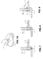
- FIG 7a
- is a perspective view of a removable, helical, auger head;
- FIG 8
- is a cross section of a second embodiment of a removable, helical, auger head, and a lower end of a shaft and an augur head;
- FIG 9
- is a third embodiment of a removable, helical, auger head;
- FIG10
- is a cross section of a fourth embodiment of a removable, helical, auger head;
- FIG 11
- is a cross section of a fifth embodiment of a removable, helical, auger head;
- FIG 11a
- is a cross section of a sixth embodiment of a removable, helical, auger head;
- FIG 12
- is a side elevation of a coupling arrangement and linear potentiometer mechanism for measuring torque on an augur head;
- FIG 13
- is a side elevation illustrating the coupling and linear potentiometer when the augur head is working;
- FIG 14
- is a perspective view of portafilter activated switch for turning on an augur; and
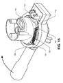
- FIG 15
- is a perspective view of the device depicted in
FIG 14 with an external housing. - As shown in
Figure 1 , a motorised compaction augur forespresso coffee machine 10 comprises anelectric motor 11 andgear train assembly 12 that are used to rotate an upper orgear shaft 13. Theupper shaft 13 is connected to thelower augur shaft 14 by aspring coupling 15. The upper end of thespring coupling 15 is attached to the upper orgear shaft 13 and the lower end of thespring coupling 15 is attached to theaugur shaft 14. Thespring coupling 15 allows thegear shaft 13 andaugur shaft 14 to rotate relative to one another after a pre-established torque limit has been reached. The instant specification discloses various mechanisms for using the angular displacement between the upper and lower shafts of the auger to achieve a useful outcome, indicate a level of compaction, perform switching functions, etc. The augur device may optionally be contained in the body of the grinder or coffee making apparatus in which it is fitted, thus containing grounds and creating less mess for the user. The device disclosed here also provides uniformity in coffee dose and tamp or compression force. - The lower end of the augur shaft carries a double
helical augur head 16. Theaugur head 16 is generally above and within aportafilter holder 17. The portafilter holder is adapted to retain and release theportafilter assembly 18 in the same way that the portafilter is held and released by the group head of an espresso machine. The diameter of theaugur head 16 is about the same as the inside diameter of the upper extremity of the portafilter interior, or thefilter basket 19 carried by theportafilter 18. - In preferred embodiments, the motorised augur is adjacent to, below or at least co-operates with a
coffee grinder 20. In this example, thegrinder 20 is a stainless steel conical burr grinder. Thegrinder 20 discharges ground coffee directly, or into adelivery chute 21 having an exit opening above theaugur head 16. - Coffee discharged by the
grinder 20 flows through the helical structure of theaugur head 16. The ground coffee is thus deposited through the auger and, in this way, fills the portafilter or filter basket from the bottom up. There is no friction or resistance between the ground coffee and the augur head until the fill level within the filter basket reaches the lower, generallyflat surface 22 of the augur head. Once the fill level within the filter basket reaches the under side of theaugur head 22, the addition of coffee grounds results in a compaction of the coffee in the filter basket or portafilter, that is below the lower surface of theaugur head 22. At first, the frictional resistance of the coffee against the underside of the augur head is negligible. However, as ground coffee continues to fill the filter basket the resistance to the rotation of the augur head increases. At some point, the tortional resistance imposed by thespring coupling 15 is overcome and the upper orgear shaft 13 begins to move away from or become rotationally displaced from the augur orlower shaft 14. That is to say, for a given number of revolutions of the motor, thegear shaft 13 rotates slightly more than theaugur shaft 14. - This rotational or angular displacement between the
gear shaft 13 and theaugur shaft 14 causes acam follower 23 that follows acircumferential cam 24 to lift or rise, or move away from the cam against a restoring force exerted by acam lifter spring 25. As the friction against the underside of the augur increases, thecam follower 23 rises until its flange or lip impinges on the mechanical contact of a mechanism, switch ormicro switch 26 or other switching means. As suggested inFigure 5 , the switch or micro switch orother mechanism 26, generally via a microprocessor orother controller 51, stops the action of the grinder'selectric motor 11 and thegrinder 20 stops producing grounds. After the grinder has stopped for a pre-established interval, the unit's timer or microprocessor causes theaugur 16 to stop. This delay insures that delivery of coffee to the portafilter from the chute has stopped and that the top surface of the grounds in the portafilter is smooth. In the alternative, as suggested byFigure 6 , the electricmotorised grinder 20 can be controlled so that it stops after a user selected interval passes from when the microswitch has been contacted. A user activated knob, dial orother selector 53 on the exterior of the grinder or coffee maker can thus be used (in conjunction with a timer or microcontroller etc.) to change the delay interval related to the grinder motor. This will cause additional grinds to be delivered, in ever increasing amount in relation to the delay. This allows the user to vary the dose and therefore the strength of the coffee delivered from the portafilter. In yet another embodiment (seeFigure 6 ), the cut off of the grinder motor is done based solely on a pre-set or user selectedtime interval 52 and thus no torque sensitive mechanism is required on the augur. - As shown in
Figure 2 , theaugur head 16 comprises one or two or more helical ramps or screws having aflat underside 22 in the area of the trailing edge or edges. - As shown in
Figure 3 , theaugur shaft 14 may retain a circumferential orother cam 30. The cam presents an upward facing constant radius orother cam surface 24 that essentially spirals around the central axis of rotation of theaugur shaft 14. Thecam lifter 23 and itsintegral activation flange 31 are carried on acoupling sleeve 32 that is affixed to thegear shaft 13. Acompression spring 25 is, in this example, carried around the coupling sleeve and interposed between the cam lifter and a through pin orother fastener 33 that is used to attach thecoupling sleeve 32 to thegear shaft 13. - As shown in
Figure 4 , the relative angular or tortional displacement between thegear shaft 13 and theaugur shaft 14 is limited to about 90° of rotation. That is, regardless of the degree of compaction of the coffee grounds, once thegear shaft 13 and augurshaft 14 are displaced by about 90°, they will then continue to rotate together. This is done by providing a recess in the lower end of thecoupling sleeve 32 that is adapted to receive anupper shoulder 36 of thecam 30 that is carried by theaugur shaft 14. The lower end of thecoupling sleeve 40 hasinternal abutments 41 that limit the rotation of thecoupling 30 relative to thecoupling sleeve 32.Protrusions 42 on the cam interfere with theabutments 41 after the pre-established degree of rotational displacement have been reached. - As suggested by
Figures 1-3 , thehelical augur head 16 is removably attached to the lowest end of arotating shaft 70. Theaugur head 16 must be retained on the shaft against the force of gravity. Theaugust head 16 must also be resistant to rotating relative to theshaft 70. As shown inFigure 7A , relative rotation between theaugur head 16 and theshaft 70 may be accomplished by providing thecentral bore 71 of theaugur head 16 with one or moreflat sides 72 that cooperate with flat surfaces on thelower end 73 of theshaft 70. As suggested byFigure 7 , theaugur head 16 is retained against the influence of gravity by amagnet 74 permanently affixed to the bottom 75 of thecentral bore 71. In this way, theaugur head 16 can be easily inserted over theshaft 70 and easily removed for cleaning or storage. In the alternative, and as shown inFigure 8 , themagnet 74 may alternately be attached to the lower end surface of theshaft 70. In this example, the augur head must be fabricated from steel. In the example ofFigure 7 , the augur head may be made from practically any suitable polymer or metal so long as theshaft 70 is fabricated from steel. - As shown in
Figure 9 , theaugur head 16 may be removably attached by way of a split ring orspring ring 76. Thesplit ring 76 is located in a first groove and cooperates with a second groove. The first groove may be in either the outer circumference of theshaft 70 or the inner surface of thebore 71. The complimentary second groove receives thering 76. In this arrangement, it is preferred that the tip of theshaft 77, below thering 76 be tapered and received by a complimentary taper in thebore 71. In some embodiments, anupper surface 78 of thehub 79 of theaugur 16 is piloted to assist with location of thetip 77 into thebore 71. - As shown in
Figure 10 , theaugur head 16 may be retained on theshaft 70 by cooperating reverse threads. In this way, friction between the augur and the coffee results in a tightening rather than loosening of thehead 16. - In another embodiment, and as shown in
Figure 11 , theaugur head 16 is retained on theshaft 70 by way of a captive ball that cooperates with a cooperating detent 8 1. Theball 80 is urged by aspring 82 toward the detent 8 1. It should be noted that the ball may be located within a radially oriented recess 83 and that the recess may be formed in either theshaft 70 or thehead 16. The detent 8 1, in the form of a pocket or circumferential groove is located on the other component.Figure 11 a illustrates than in any of the embodiments relating to the attachment of theauger head 202 to theshaft 203 , the auger may carry themale coupling component 200 and the shaft may carry the bore orfemale coupling component 201. - As shown in
Figures 12 and 13 , acoupling arrangement 90 between two adjacent portions of therotating augur shaft shaft 92. Thecoupling arrangement 90 consists of a lower hub orcam 93 and an upper hub orcam follower 94. Aperiphery of thelower hub 93 is provided with one or moresimilar ramps 95. When the rotation of thelower hub 93 is resisted by the action of the augur head on the ground coffee below it, the upper hub becomes displaced vertically upward 96, moving away from the cam or lower hub (as shown inFigure 13 ). This is because theupper hub 94 has one or more vertically extendingfingers 97. Thefingers 97 have optionally lowerinclined surfaces 98 that cooperate with theramps 95. As thelower hub 93 is not able to move vertically, the upper hub rises or moves 96 against the action of acompression spring 99. Thus, the amount of vertical (or other)motion 96 is proportional to or representative of the aforementioned resistance or torque exerted on the auger head and itslower shaft 92. The amount ofvertical motion 96 is measured by a mechanism, sensor mechanism or an instrument or potentiometer such as alinear potentiometer 100. Thevertical motion 96 of theupper hub 94 is transmitted to thevertical slider 101 of the sensor orpotentiometer 100 by alever 102. The lever has afirst end 103 comprising a wear resistantterminal portion 104. Thelever 102 has anintermediate pivot 105. Thus, thevertical motion 96 of theupper hub 94 is transmitted by thelever 102 into a linear motion of the potentiometer'sslider 101. Theother end 110 of thelever 102 comprises an elongated slot 103a so that only the vertical motion of theend 110 is transmitted to theslider 101. The motion of the lever may be measured or detected in other ways and the motion may be used to activate a switch, sensor or mechanism for achieving a useful purpose in an auger or grinder. - As shown in
Figure 14 , a switch ormicro switch 140 maybe used to initiate the action of the motorised auger. In this example, theportafilter 141 has an upper rim on which is formed one or more outwardly extendingtabs 142. These tabs are inserted into co-operating slots in the female component of a bayonet mechanism that holds the portafilter during coffee extraction. In this example, anintermediate ring 143 has one or moreintegral bumpers 144. After the initial insertion of the portafilter into the female bayonet component, rotation of the handle, generally in a anti-clockwise motion (when seen from above) causes thefront edge 145 of atab 142 to contact a trailing edge of abumper 144. Further rotation of the portafilter handle 146 causes a rotation of thering 143. The ring has anactivation tab 147 when the ring is rotated, the leading edge of theactivation tab 147 depresses themechanical contact 148 of themicro switch 140. The subsequent or electrical contact within themicro switch 140 is used by the device's microprocessor to initiate the action of the auger. - As shown in
Figure 15 , theintermediate ring 143 has fixing posts, in this example one or more vertical fixing posts 150. A co-operating fixingpost 151 is located on ahousing 152 or otherwise adjacent to but not connected to thering 143. Atension spring 153 extends between the twoposts spring 153 returns therotating ring 143 to its initial position. Theintermediate ring 143 allows themicro switch 140 to be mechanically isolated from ground coffee that is being transported by the portafilter. It would be appreciated that various spring arrangements between the intermediate ring and any adjacent structure maybe used to anchor the ends of a resilient spring or other bias member to accomplish the return action of the intermediate ring. In other embodiments, thetabs 142 of the portafilter make contact the switch ormicro switch 140 in other ways including direct contact or contact through a flexible membrane (not shown). - While the present invention has been disclosed with reference to particular details of construction, these should be understood as having been provided by a way of example and not as limitations to the scope of the invention.
Claims (5)
- A motorised augur device (10) for a portafilter (141) having outwardly extending tabs (142), comprising:a female bayonet mechanism for receiving the portafilter (141), the mechanism having slots for receiving the portafilter tabs (142);a rotating ring (143) from which extends a bumper (144) for making contact with one of the portafilter tabs (142);the rotating ring (143) having an activation tab (147); andan electrical switch (140) that is acted upon when contacted by the activation tab (147).
- The device of claim 1, further comprising:a processor (51) that co-operates with the switch (140) to initiate the augur (10) in response to the switch (140).
- The device of either of claims 1 or 2, wherein:a spring (153) extends between the ring (143) and a housing (152) adjacent to the ring, the spring (153) returning the ring (143) to an initial position from which it was rotated.
- The device of claim 3, wherein:the spring (153) is attached:to the ring (143) at a first post (150) located on the ring (143); andto a second post (151) located on the housing (152).
- The device of any of claims 1-4, wherein:the ring (143) mechanically isolates the electrical switch (140) from coffee transported by the portafilter (141).
Applications Claiming Priority (2)
| Application Number | Priority Date | Filing Date | Title |
|---|---|---|---|
| AU2010904466A AU2010904466A0 (en) | 2010-10-05 | Tamping Augur | |
| EP11830113.4A EP2624730B1 (en) | 2010-10-05 | 2011-10-05 | Motorised automatic compaction auger device |
Related Parent Applications (2)
| Application Number | Title | Priority Date | Filing Date |
|---|---|---|---|
| EP11830113.4A Division-Into EP2624730B1 (en) | 2010-10-05 | 2011-10-05 | Motorised automatic compaction auger device |
| EP11830113.4A Division EP2624730B1 (en) | 2010-10-05 | 2011-10-05 | Motorised automatic compaction auger device |
Publications (2)
| Publication Number | Publication Date |
|---|---|
| EP2962607A1 true EP2962607A1 (en) | 2016-01-06 |
| EP2962607B1 EP2962607B1 (en) | 2017-03-22 |
Family
ID=45927125
Family Applications (2)
| Application Number | Title | Priority Date | Filing Date |
|---|---|---|---|
| EP11830113.4A Active EP2624730B1 (en) | 2010-10-05 | 2011-10-05 | Motorised automatic compaction auger device |
| EP15176358.8A Active EP2962607B1 (en) | 2010-10-05 | 2011-10-05 | Motorised compaction auger device |
Family Applications Before (1)
| Application Number | Title | Priority Date | Filing Date |
|---|---|---|---|
| EP11830113.4A Active EP2624730B1 (en) | 2010-10-05 | 2011-10-05 | Motorised automatic compaction auger device |
Country Status (6)
| Country | Link |
|---|---|
| US (1) | US9301637B2 (en) |
| EP (2) | EP2624730B1 (en) |
| CN (2) | CN103188971B (en) |
| AU (1) | AU2011313808B2 (en) |
| RU (1) | RU2591111C2 (en) |
| WO (1) | WO2012045112A1 (en) |
Families Citing this family (30)
| Publication number | Priority date | Publication date | Assignee | Title |
|---|---|---|---|---|
| US10376091B2 (en) * | 2011-07-21 | 2019-08-13 | Breville Pty Limited | Coffee grinder apparatus |
| US12582260B2 (en) | 2009-01-29 | 2026-03-24 | Breville Pty Ltd | Coffee grinder apparatus |
| JP2012516194A (en) * | 2009-02-01 | 2012-07-19 | エスプレッソ コーポレイション リミテッド | Waste reduction device |
| CN105101851B (en) * | 2013-04-08 | 2018-11-30 | 布瑞威利私人有限公司 | Improved coffee grinder |
| ITVE20130029A1 (en) | 2013-06-17 | 2014-12-18 | Mazzer Luigi S R L | PRESSING DEVICE FOR COFFEE POWDER IN THE FILTER HOLDER.- |
| US10881240B2 (en) | 2013-10-08 | 2021-01-05 | Breville Pty Limited | Adjustable portafilter and grind adjustment |
| US10188238B2 (en) | 2014-03-11 | 2019-01-29 | Starbucks Corporation | Beverage production machines and methods with tamping assembly |
| DE102014225764B4 (en) * | 2014-12-12 | 2017-03-30 | Bernhard Schultes | Device for tamping coffee |
| CN105105633B (en) | 2015-08-28 | 2017-10-03 | 广东新宝电器股份有限公司 | Automatic powder falling coffee funnel and coffee machine using same |
| EP3463010B1 (en) * | 2016-06-02 | 2023-10-18 | Invento Pty Ltd | A coffee dispenser |
| US11021284B2 (en) | 2016-06-20 | 2021-06-01 | Adrian Rivera | Method of constructing an espresso cartridge |
| US11840397B2 (en) | 2016-06-20 | 2023-12-12 | Adrian Rivera | Method of constructing a beverage brewing cartridge |
| US10912407B2 (en) | 2016-06-20 | 2021-02-09 | Adrian Rivera | Method of constructing an espresso cartridge |
| US9586709B1 (en) * | 2016-06-20 | 2017-03-07 | Adrian Rivera | Apparatus and method for constructing espresso cartridges |
| CN106580103B (en) * | 2016-11-29 | 2020-11-27 | 宁波夏纳电器有限公司 | Extraction method of Italian coffee |
| IT201600122741A1 (en) | 2016-12-02 | 2018-06-02 | Gruppo Cimbali Spa | Equipment for pressing a dose of coffee into the filter holder. |
| EP3400853A1 (en) * | 2017-05-12 | 2018-11-14 | Yang, Yu-Ming | Coffee powder distribution device |
| IT201700090275A1 (en) * | 2017-08-03 | 2019-02-03 | De Longhi Appliances Srl | DEVICE FOR PRESSING A DOSE OF GROUND POWDER COFFEE |
| CN212755306U (en) * | 2019-05-17 | 2021-03-23 | 星速科技有限公司 | Coffee powder press |
| IT201900019088A1 (en) | 2019-10-16 | 2021-04-16 | La Marzocco Srl | Hopper for coffee grinder machine equipped with a lower closure device to save beans and coffee grinder machine equipped with this hopper |
| CN219940342U (en) * | 2020-12-23 | 2023-11-03 | 布瑞威利私人有限公司 | Compacting mechanism and coffee grinder |
| CN114766915B (en) * | 2022-04-25 | 2023-11-17 | 瑞鼎机电科技(昆山)有限公司 | Coffee machine handle and production process |
| US20240010373A1 (en) * | 2022-07-05 | 2024-01-11 | Adrian Rivera | Beverage Brewing Cartridge, Construction Kit, and Method of Constructing a Beverage Cartridge |
| CN115381304B (en) * | 2022-08-25 | 2025-03-04 | 广东萧泰斯电气有限公司 | Powder pressing machine and powder pressing method thereof |
| WO2024055051A1 (en) * | 2022-09-15 | 2024-03-21 | Gmainer Alexander | Device for a portafilter that can be filled with coffee powder |
| IT202200020082A1 (en) * | 2022-09-29 | 2024-03-29 | Ambrodesign Sas Di Marco Ambrosini & C | APPARATUS FOR GRINDING AND FILLING A FILTER WITH POWDERED COFFEE TO BE CONNECTED TO A MACHINE FOR DISPENSING COFFEE INTO A CUP |
| WO2025155323A1 (en) | 2024-01-18 | 2025-07-24 | Sharkninja Operating Llc | Preventing coffee bean grinder jamming |
| US12369744B1 (en) | 2024-01-18 | 2025-07-29 | Sharkninja Operating Llc | Preparation of beverage machines for cold beverage brewing |
| WO2025155321A1 (en) | 2024-01-18 | 2025-07-24 | Sharkninja Operating Llc | Suggesting coffee bean grind size for beverage machines |
| US12304675B1 (en) * | 2025-01-16 | 2025-05-20 | Shenzhen Aowei Technology Co., LTD | Material encapsulation device |
Citations (2)
| Publication number | Priority date | Publication date | Assignee | Title |
|---|---|---|---|---|
| US5463933A (en) * | 1993-04-29 | 1995-11-07 | Moulinex S.A. | Device for locking a filter carrier on an infusion head of an espresso coffeemaker |
| US6095032A (en) | 1998-11-06 | 2000-08-01 | La Marzocco International L.L.C. | Coffee grinding, portioning, and pressing device |
Family Cites Families (27)
| Publication number | Priority date | Publication date | Assignee | Title |
|---|---|---|---|---|
| LU40768A1 (en) * | 1961-10-31 | 1963-05-02 | ||
| ES433322A1 (en) * | 1974-01-14 | 1977-02-16 | Cailliot S L Y L | Coffee mill |
| US3973922A (en) * | 1974-04-29 | 1976-08-10 | Williams Thomas A | Artificial logs and log-making method and apparatus |
| US4172413A (en) * | 1978-07-03 | 1979-10-30 | Roseberry Homer R | Beverage preparing apparatus |
| IT207077Z2 (en) * | 1985-09-12 | 1987-11-23 | Piana Giuseppe Stefano | AUTOMATIC MACHINE FOR THE PREPARATION OF ESPRESSO COFFEE |
| US5127318A (en) * | 1988-12-12 | 1992-07-07 | Selsys Corporation | Apparatus and process for extracting espresso coffee |
| DE4139804C1 (en) * | 1991-12-03 | 1993-05-13 | Cis Elektrogeraete Ag, Hinwil, Ch | |
| US5224414A (en) * | 1992-09-25 | 1993-07-06 | Grindmaster Corporation | Moisture prevention valve in an apparatus for the preparation of liquid beverage from solid and liquid components |
| US5241898B1 (en) * | 1992-09-25 | 1999-02-09 | Grindmaster Corp | Coffee dispenser and brewer apparatus |
| US5542342A (en) * | 1995-08-08 | 1996-08-06 | Grindmaster Corporation | Coffee grinder and brewer apparatus with basket sensing and grind only feature |
| US5749776A (en) * | 1996-12-02 | 1998-05-12 | Evans Machine Company, Inc. | Meat deboning apparatus |
| US6339985B1 (en) * | 1998-02-03 | 2002-01-22 | Robert R. Whitney | Coffee maker |
| FR2793129B1 (en) * | 1999-05-04 | 2001-06-29 | Seb Sa | EXPRESSO TYPE COFFEE MACHINE COMPRISING HYDRAULIC MEANS FOR COMPRESSING THE GRIND |
| US6681871B2 (en) * | 2002-04-19 | 2004-01-27 | Arthur E. Drumm | Auger tool for boring |
| US6988444B1 (en) * | 2002-05-15 | 2006-01-24 | Grindmaster Corporation | Combination grinder and brewer |
| US20050193891A1 (en) * | 2004-03-08 | 2005-09-08 | Brent Garson | Espresso making apparatus and method of brewing espresso |
| US7537138B2 (en) * | 2005-06-20 | 2009-05-26 | Nestec S.A. | Methods and systems for delivering foamed beverages from liquid concentrates |
| ITLE20060009A1 (en) * | 2006-03-10 | 2006-06-09 | Giovanni Spinelli | INVENTION IN THE FIELD OF COFFEE MACHINES A FAP / CAPSULES |
| ITFI20060222A1 (en) * | 2006-09-08 | 2008-03-09 | Saeco Ipr Ltd | DISPENSER DEVICE FOR PRODUCTS COMBINED FOR THE PREPARATION OF BEVERAGES, AND MACHINE CONTAINED AS THE DISPENSER DEVICE |
| ITFI20060281A1 (en) * | 2006-11-14 | 2008-05-15 | Saeco Ipr Ltd | GRINDING ORGANS FOR A COFFEE MILL DEVICE AND A COFFEE MACHINE INCLUDING SUCH A DEVICE. |
| US7912579B2 (en) * | 2007-01-10 | 2011-03-22 | Crane Merchandising Systems | Automatic cup detection and associated customer interface for vending apparatus and method therefor |
| ITFI20070049A1 (en) * | 2007-02-27 | 2008-08-28 | Saeco Ipr Ltd | METHOD FOR THE AUTOMATIC ADJUSTMENT OF THE AMOUNT OF COFFEE AND COFFEE MACHINE THAT USE THE SAID METHOD. |
| GB2447678A (en) * | 2007-03-21 | 2008-09-24 | Dyson Technology Ltd | Dispensing ingredients from hoppers |
| CN201223317Y (en) * | 2008-06-18 | 2009-04-22 | 厦门灿坤实业股份有限公司 | Novel full-automatic bean grinder |
| CN201256891Y (en) * | 2008-09-22 | 2009-06-17 | 佛山市三水合成电器实业有限公司 | Pulverizing and extruding device of coffee bean |
| ES2363418T3 (en) * | 2009-03-20 | 2011-08-03 | Gruppo Cimbali S.P.A. | APPARATUS FOR THE PREPARATION AND DISPENSATION OF INFUSIONS, PARTICULARLY COFFEE, IN VARIABLE VOLUMETRIC DOSE. |
| CN105101851B (en) * | 2013-04-08 | 2018-11-30 | 布瑞威利私人有限公司 | Improved coffee grinder |
-
2011
- 2011-10-05 CN CN201180046905.7A patent/CN103188971B/en active Active
- 2011-10-05 AU AU2011313808A patent/AU2011313808B2/en active Active
- 2011-10-05 EP EP11830113.4A patent/EP2624730B1/en active Active
- 2011-10-05 US US13/821,993 patent/US9301637B2/en active Active
- 2011-10-05 EP EP15176358.8A patent/EP2962607B1/en active Active
- 2011-10-05 CN CN201610100940.7A patent/CN105686645B/en active Active
- 2011-10-05 WO PCT/AU2011/001263 patent/WO2012045112A1/en not_active Ceased
- 2011-10-05 RU RU2013120292/12A patent/RU2591111C2/en active
Patent Citations (2)
| Publication number | Priority date | Publication date | Assignee | Title |
|---|---|---|---|---|
| US5463933A (en) * | 1993-04-29 | 1995-11-07 | Moulinex S.A. | Device for locking a filter carrier on an infusion head of an espresso coffeemaker |
| US6095032A (en) | 1998-11-06 | 2000-08-01 | La Marzocco International L.L.C. | Coffee grinding, portioning, and pressing device |
Also Published As
| Publication number | Publication date |
|---|---|
| RU2591111C2 (en) | 2016-07-10 |
| CN105686645A (en) | 2016-06-22 |
| EP2624730B1 (en) | 2016-04-06 |
| US9301637B2 (en) | 2016-04-05 |
| CN105686645B (en) | 2018-11-23 |
| CN103188971A (en) | 2013-07-03 |
| RU2013120292A (en) | 2014-11-20 |
| AU2011313808A1 (en) | 2013-03-28 |
| AU2011313808B2 (en) | 2015-05-28 |
| CN103188971B (en) | 2016-04-13 |
| AU2015205905A1 (en) | 2015-08-20 |
| EP2624730A1 (en) | 2013-08-14 |
| EP2962607B1 (en) | 2017-03-22 |
| AU2011313808A2 (en) | 2013-04-04 |
| EP2624730A4 (en) | 2015-01-21 |
| WO2012045112A1 (en) | 2012-04-12 |
| US20130167729A1 (en) | 2013-07-04 |
Similar Documents
| Publication | Publication Date | Title |
|---|---|---|
| EP2962607B1 (en) | Motorised compaction auger device | |
| US9744739B2 (en) | Tamping augur | |
| AU2023200409B2 (en) | Improvements to coffee grinder | |
| CN102665502B (en) | Device for dispensing ground coffee and machine comprising such a device | |
| KR102823899B1 (en) | Apparatus for metering coffee beans | |
| EP2544571B1 (en) | Conical burr grinder | |
| EP3430956B1 (en) | Device for resetting the position of the grinding wheels in a grinder | |
| AU2012209041B2 (en) | Coffee tamping apparatus | |
| EP2897505B1 (en) | Coffee grinder, coffee machine containing a coffee grinder and method for grinding coffee beans | |
| RU2768783C2 (en) | Device for pressing a portion of ground powdered coffee | |
| CA2471331C (en) | Timer tea maker | |
| CN105407770B (en) | Machine for preparing beverages with removable filter-holder and element for selecting the operating mode of the machine | |
| US11083326B2 (en) | Ground coffee dispenser for a coffee machine provided with a turbine with curved blades | |
| AU2021221718A1 (en) | Coffee compacting assembly and tamper | |
| CN218651404U (en) | Tea making device | |
| EP4699499A1 (en) | System for the assisted setting of the grinding point in coffee grinders |
Legal Events
| Date | Code | Title | Description |
|---|---|---|---|
| PUAI | Public reference made under article 153(3) epc to a published international application that has entered the european phase |
Free format text: ORIGINAL CODE: 0009012 |
|
| AC | Divisional application: reference to earlier application |
Ref document number: 2624730 Country of ref document: EP Kind code of ref document: P |
|
| AK | Designated contracting states |
Kind code of ref document: A1 Designated state(s): AL AT BE BG CH CY CZ DE DK EE ES FI FR GB GR HR HU IE IS IT LI LT LU LV MC MK MT NL NO PL PT RO RS SE SI SK SM TR |
|
| 17P | Request for examination filed |
Effective date: 20160705 |
|
| RBV | Designated contracting states (corrected) |
Designated state(s): AL AT BE BG CH CY CZ DE DK EE ES FI FR GB GR HR HU IE IS IT LI LT LU LV MC MK MT NL NO PL PT RO RS SE SI SK SM TR |
|
| GRAP | Despatch of communication of intention to grant a patent |
Free format text: ORIGINAL CODE: EPIDOSNIGR1 |
|
| INTG | Intention to grant announced |
Effective date: 20161019 |
|
| GRAS | Grant fee paid |
Free format text: ORIGINAL CODE: EPIDOSNIGR3 |
|
| GRAA | (expected) grant |
Free format text: ORIGINAL CODE: 0009210 |
|
| AC | Divisional application: reference to earlier application |
Ref document number: 2624730 Country of ref document: EP Kind code of ref document: P |
|
| AK | Designated contracting states |
Kind code of ref document: B1 Designated state(s): AL AT BE BG CH CY CZ DE DK EE ES FI FR GB GR HR HU IE IS IT LI LT LU LV MC MK MT NL NO PL PT RO RS SE SI SK SM TR |
|
| REG | Reference to a national code |
Ref country code: GB Ref legal event code: FG4D |
|
| REG | Reference to a national code |
Ref country code: CH Ref legal event code: EP |
|
| REG | Reference to a national code |
Ref country code: AT Ref legal event code: REF Ref document number: 876836 Country of ref document: AT Kind code of ref document: T Effective date: 20170415 |
|
| REG | Reference to a national code |
Ref country code: IE Ref legal event code: FG4D |
|
| REG | Reference to a national code |
Ref country code: DE Ref legal event code: R096 Ref document number: 602011036363 Country of ref document: DE |
|
| REG | Reference to a national code |
Ref country code: NL Ref legal event code: MP Effective date: 20170322 |
|
| PG25 | Lapsed in a contracting state [announced via postgrant information from national office to epo] |
Ref country code: GR Free format text: LAPSE BECAUSE OF FAILURE TO SUBMIT A TRANSLATION OF THE DESCRIPTION OR TO PAY THE FEE WITHIN THE PRESCRIBED TIME-LIMIT Effective date: 20170623 Ref country code: HR Free format text: LAPSE BECAUSE OF FAILURE TO SUBMIT A TRANSLATION OF THE DESCRIPTION OR TO PAY THE FEE WITHIN THE PRESCRIBED TIME-LIMIT Effective date: 20170322 Ref country code: NO Free format text: LAPSE BECAUSE OF FAILURE TO SUBMIT A TRANSLATION OF THE DESCRIPTION OR TO PAY THE FEE WITHIN THE PRESCRIBED TIME-LIMIT Effective date: 20170622 Ref country code: FI Free format text: LAPSE BECAUSE OF FAILURE TO SUBMIT A TRANSLATION OF THE DESCRIPTION OR TO PAY THE FEE WITHIN THE PRESCRIBED TIME-LIMIT Effective date: 20170322 Ref country code: LT Free format text: LAPSE BECAUSE OF FAILURE TO SUBMIT A TRANSLATION OF THE DESCRIPTION OR TO PAY THE FEE WITHIN THE PRESCRIBED TIME-LIMIT Effective date: 20170322 |
|
| REG | Reference to a national code |
Ref country code: LT Ref legal event code: MG4D |
|
| REG | Reference to a national code |
Ref country code: AT Ref legal event code: MK05 Ref document number: 876836 Country of ref document: AT Kind code of ref document: T Effective date: 20170322 |
|
| PG25 | Lapsed in a contracting state [announced via postgrant information from national office to epo] |
Ref country code: LV Free format text: LAPSE BECAUSE OF FAILURE TO SUBMIT A TRANSLATION OF THE DESCRIPTION OR TO PAY THE FEE WITHIN THE PRESCRIBED TIME-LIMIT Effective date: 20170322 Ref country code: RS Free format text: LAPSE BECAUSE OF FAILURE TO SUBMIT A TRANSLATION OF THE DESCRIPTION OR TO PAY THE FEE WITHIN THE PRESCRIBED TIME-LIMIT Effective date: 20170322 Ref country code: SE Free format text: LAPSE BECAUSE OF FAILURE TO SUBMIT A TRANSLATION OF THE DESCRIPTION OR TO PAY THE FEE WITHIN THE PRESCRIBED TIME-LIMIT Effective date: 20170322 Ref country code: BG Free format text: LAPSE BECAUSE OF FAILURE TO SUBMIT A TRANSLATION OF THE DESCRIPTION OR TO PAY THE FEE WITHIN THE PRESCRIBED TIME-LIMIT Effective date: 20170622 |
|
| REG | Reference to a national code |
Ref country code: FR Ref legal event code: PLFP Year of fee payment: 7 |
|
| PG25 | Lapsed in a contracting state [announced via postgrant information from national office to epo] |
Ref country code: NL Free format text: LAPSE BECAUSE OF FAILURE TO SUBMIT A TRANSLATION OF THE DESCRIPTION OR TO PAY THE FEE WITHIN THE PRESCRIBED TIME-LIMIT Effective date: 20170322 |
|
| PG25 | Lapsed in a contracting state [announced via postgrant information from national office to epo] |
Ref country code: CZ Free format text: LAPSE BECAUSE OF FAILURE TO SUBMIT A TRANSLATION OF THE DESCRIPTION OR TO PAY THE FEE WITHIN THE PRESCRIBED TIME-LIMIT Effective date: 20170322 Ref country code: RO Free format text: LAPSE BECAUSE OF FAILURE TO SUBMIT A TRANSLATION OF THE DESCRIPTION OR TO PAY THE FEE WITHIN THE PRESCRIBED TIME-LIMIT Effective date: 20170322 Ref country code: SK Free format text: LAPSE BECAUSE OF FAILURE TO SUBMIT A TRANSLATION OF THE DESCRIPTION OR TO PAY THE FEE WITHIN THE PRESCRIBED TIME-LIMIT Effective date: 20170322 Ref country code: ES Free format text: LAPSE BECAUSE OF FAILURE TO SUBMIT A TRANSLATION OF THE DESCRIPTION OR TO PAY THE FEE WITHIN THE PRESCRIBED TIME-LIMIT Effective date: 20170322 Ref country code: AT Free format text: LAPSE BECAUSE OF FAILURE TO SUBMIT A TRANSLATION OF THE DESCRIPTION OR TO PAY THE FEE WITHIN THE PRESCRIBED TIME-LIMIT Effective date: 20170322 Ref country code: EE Free format text: LAPSE BECAUSE OF FAILURE TO SUBMIT A TRANSLATION OF THE DESCRIPTION OR TO PAY THE FEE WITHIN THE PRESCRIBED TIME-LIMIT Effective date: 20170322 |
|
| PG25 | Lapsed in a contracting state [announced via postgrant information from national office to epo] |
Ref country code: SM Free format text: LAPSE BECAUSE OF FAILURE TO SUBMIT A TRANSLATION OF THE DESCRIPTION OR TO PAY THE FEE WITHIN THE PRESCRIBED TIME-LIMIT Effective date: 20170322 Ref country code: PL Free format text: LAPSE BECAUSE OF FAILURE TO SUBMIT A TRANSLATION OF THE DESCRIPTION OR TO PAY THE FEE WITHIN THE PRESCRIBED TIME-LIMIT Effective date: 20170322 Ref country code: PT Free format text: LAPSE BECAUSE OF FAILURE TO SUBMIT A TRANSLATION OF THE DESCRIPTION OR TO PAY THE FEE WITHIN THE PRESCRIBED TIME-LIMIT Effective date: 20170724 Ref country code: IS Free format text: LAPSE BECAUSE OF FAILURE TO SUBMIT A TRANSLATION OF THE DESCRIPTION OR TO PAY THE FEE WITHIN THE PRESCRIBED TIME-LIMIT Effective date: 20170722 |
|
| REG | Reference to a national code |
Ref country code: DE Ref legal event code: R097 Ref document number: 602011036363 Country of ref document: DE |
|
| PLBE | No opposition filed within time limit |
Free format text: ORIGINAL CODE: 0009261 |
|
| STAA | Information on the status of an ep patent application or granted ep patent |
Free format text: STATUS: NO OPPOSITION FILED WITHIN TIME LIMIT |
|
| PG25 | Lapsed in a contracting state [announced via postgrant information from national office to epo] |
Ref country code: DK Free format text: LAPSE BECAUSE OF FAILURE TO SUBMIT A TRANSLATION OF THE DESCRIPTION OR TO PAY THE FEE WITHIN THE PRESCRIBED TIME-LIMIT Effective date: 20170322 |
|
| 26N | No opposition filed |
Effective date: 20180102 |
|
| PG25 | Lapsed in a contracting state [announced via postgrant information from national office to epo] |
Ref country code: SI Free format text: LAPSE BECAUSE OF FAILURE TO SUBMIT A TRANSLATION OF THE DESCRIPTION OR TO PAY THE FEE WITHIN THE PRESCRIBED TIME-LIMIT Effective date: 20170322 |
|
| PG25 | Lapsed in a contracting state [announced via postgrant information from national office to epo] |
Ref country code: MC Free format text: LAPSE BECAUSE OF FAILURE TO SUBMIT A TRANSLATION OF THE DESCRIPTION OR TO PAY THE FEE WITHIN THE PRESCRIBED TIME-LIMIT Effective date: 20170322 |
|
| REG | Reference to a national code |
Ref country code: CH Ref legal event code: PL |
|
| REG | Reference to a national code |
Ref country code: IE Ref legal event code: MM4A |
|
| PG25 | Lapsed in a contracting state [announced via postgrant information from national office to epo] |
Ref country code: CH Free format text: LAPSE BECAUSE OF NON-PAYMENT OF DUE FEES Effective date: 20171031 Ref country code: LI Free format text: LAPSE BECAUSE OF NON-PAYMENT OF DUE FEES Effective date: 20171031 Ref country code: LU Free format text: LAPSE BECAUSE OF NON-PAYMENT OF DUE FEES Effective date: 20171005 |
|
| REG | Reference to a national code |
Ref country code: BE Ref legal event code: MM Effective date: 20171031 |
|
| PG25 | Lapsed in a contracting state [announced via postgrant information from national office to epo] |
Ref country code: BE Free format text: LAPSE BECAUSE OF NON-PAYMENT OF DUE FEES Effective date: 20171031 |
|
| PG25 | Lapsed in a contracting state [announced via postgrant information from national office to epo] |
Ref country code: MT Free format text: LAPSE BECAUSE OF NON-PAYMENT OF DUE FEES Effective date: 20171005 |
|
| REG | Reference to a national code |
Ref country code: FR Ref legal event code: PLFP Year of fee payment: 8 |
|
| PG25 | Lapsed in a contracting state [announced via postgrant information from national office to epo] |
Ref country code: IE Free format text: LAPSE BECAUSE OF NON-PAYMENT OF DUE FEES Effective date: 20171005 |
|
| PG25 | Lapsed in a contracting state [announced via postgrant information from national office to epo] |
Ref country code: HU Free format text: LAPSE BECAUSE OF FAILURE TO SUBMIT A TRANSLATION OF THE DESCRIPTION OR TO PAY THE FEE WITHIN THE PRESCRIBED TIME-LIMIT; INVALID AB INITIO Effective date: 20111005 |
|
| PG25 | Lapsed in a contracting state [announced via postgrant information from national office to epo] |
Ref country code: CY Free format text: LAPSE BECAUSE OF FAILURE TO SUBMIT A TRANSLATION OF THE DESCRIPTION OR TO PAY THE FEE WITHIN THE PRESCRIBED TIME-LIMIT Effective date: 20170322 |
|
| PG25 | Lapsed in a contracting state [announced via postgrant information from national office to epo] |
Ref country code: MK Free format text: LAPSE BECAUSE OF FAILURE TO SUBMIT A TRANSLATION OF THE DESCRIPTION OR TO PAY THE FEE WITHIN THE PRESCRIBED TIME-LIMIT Effective date: 20170322 |
|
| PG25 | Lapsed in a contracting state [announced via postgrant information from national office to epo] |
Ref country code: TR Free format text: LAPSE BECAUSE OF FAILURE TO SUBMIT A TRANSLATION OF THE DESCRIPTION OR TO PAY THE FEE WITHIN THE PRESCRIBED TIME-LIMIT Effective date: 20170322 |
|
| PG25 | Lapsed in a contracting state [announced via postgrant information from national office to epo] |
Ref country code: AL Free format text: LAPSE BECAUSE OF FAILURE TO SUBMIT A TRANSLATION OF THE DESCRIPTION OR TO PAY THE FEE WITHIN THE PRESCRIBED TIME-LIMIT Effective date: 20170322 |
|
| REG | Reference to a national code |
Ref country code: DE Ref legal event code: R082 Ref document number: 602011036363 Country of ref document: DE Representative=s name: KRAUS & LEDERER PARTGMBB, DE |
|
| PGFP | Annual fee paid to national office [announced via postgrant information from national office to epo] |
Ref country code: IT Payment date: 20250922 Year of fee payment: 15 |
|
| PGFP | Annual fee paid to national office [announced via postgrant information from national office to epo] |
Ref country code: GB Payment date: 20250904 Year of fee payment: 15 |
|
| PGFP | Annual fee paid to national office [announced via postgrant information from national office to epo] |
Ref country code: FR Payment date: 20250922 Year of fee payment: 15 |
|
| PGFP | Annual fee paid to national office [announced via postgrant information from national office to epo] |
Ref country code: DE Payment date: 20250902 Year of fee payment: 15 |