EP2962447B1 - Portable radio having accessory interface - Google Patents
Portable radio having accessory interface Download PDFInfo
- Publication number
- EP2962447B1 EP2962447B1 EP14710083.8A EP14710083A EP2962447B1 EP 2962447 B1 EP2962447 B1 EP 2962447B1 EP 14710083 A EP14710083 A EP 14710083A EP 2962447 B1 EP2962447 B1 EP 2962447B1
- Authority
- EP
- European Patent Office
- Prior art keywords
- hole
- portable radio
- interface
- housing
- feature
- Prior art date
- Legal status (The legal status is an assumption and is not a legal conclusion. Google has not performed a legal analysis and makes no representation as to the accuracy of the status listed.)
- Active
Links
Images



Classifications
-
- H—ELECTRICITY
- H04—ELECTRIC COMMUNICATION TECHNIQUE
- H04B—TRANSMISSION
- H04B1/00—Details of transmission systems, not covered by a single one of groups H04B3/00 - H04B13/00; Details of transmission systems not characterised by the medium used for transmission
- H04B1/38—Transceivers, i.e. devices in which transmitter and receiver form a structural unit and in which at least one part is used for functions of transmitting and receiving
- H04B1/3827—Portable transceivers
- H04B1/3888—Arrangements for carrying or protecting transceivers
-
- H—ELECTRICITY
- H02—GENERATION; CONVERSION OR DISTRIBUTION OF ELECTRIC POWER
- H02J—ELECTRIC POWER NETWORKS; CIRCUIT ARRANGEMENTS OR SYSTEMS FOR SUPPLYING OR DISTRIBUTING ELECTRIC POWER; SYSTEMS FOR STORING ELECTRIC ENERGY
- H02J7/00—Circuit arrangements for charging or discharging batteries or for supplying loads from batteries
- H02J7/70—Circuit arrangements for charging or discharging batteries or for supplying loads from batteries characterised by the mechanical construction
- H02J7/731—Circuit arrangements for charging or discharging batteries or for supplying loads from batteries characterised by the mechanical construction specially adapted for holding portable devices containing batteries
-
- H—ELECTRICITY
- H04—ELECTRIC COMMUNICATION TECHNIQUE
- H04B—TRANSMISSION
- H04B1/00—Details of transmission systems, not covered by a single one of groups H04B3/00 - H04B13/00; Details of transmission systems not characterised by the medium used for transmission
- H04B1/38—Transceivers, i.e. devices in which transmitter and receiver form a structural unit and in which at least one part is used for functions of transmitting and receiving
- H04B1/3827—Portable transceivers
- H04B1/3833—Hand-held transceivers
-
- H—ELECTRICITY
- H04—ELECTRIC COMMUNICATION TECHNIQUE
- H04B—TRANSMISSION
- H04B1/00—Details of transmission systems, not covered by a single one of groups H04B3/00 - H04B13/00; Details of transmission systems not characterised by the medium used for transmission
- H04B1/38—Transceivers, i.e. devices in which transmitter and receiver form a structural unit and in which at least one part is used for functions of transmitting and receiving
- H04B1/3827—Portable transceivers
- H04B1/385—Transceivers carried on the body, e.g. in helmets
-
- H—ELECTRICITY
- H04—ELECTRIC COMMUNICATION TECHNIQUE
- H04B—TRANSMISSION
- H04B1/00—Details of transmission systems, not covered by a single one of groups H04B3/00 - H04B13/00; Details of transmission systems not characterised by the medium used for transmission
- H04B1/38—Transceivers, i.e. devices in which transmitter and receiver form a structural unit and in which at least one part is used for functions of transmitting and receiving
- H04B1/3827—Portable transceivers
- H04B1/3883—Arrangements for mounting batteries or battery chargers
-
- H—ELECTRICITY
- H04—ELECTRIC COMMUNICATION TECHNIQUE
- H04M—TELEPHONIC COMMUNICATION
- H04M1/00—Substation equipment, e.g. for use by subscribers
- H04M1/02—Constructional features of telephone sets
- H04M1/0202—Portable telephone sets, e.g. cordless phones, mobile phones or bar type handsets
- H04M1/0254—Portable telephone sets, e.g. cordless phones, mobile phones or bar type handsets comprising one or a plurality of mechanically detachable modules
-
- A—HUMAN NECESSITIES
- A45—HAND OR TRAVELLING ARTICLES
- A45F—TRAVELLING OR CAMP EQUIPMENT: SACKS OR PACKS CARRIED ON THE BODY
- A45F5/00—Holders or carriers for hand articles; Holders or carriers for use while travelling or camping
- A45F2005/006—Holders or carriers for hand articles; Holders or carriers for use while travelling or camping comprising a suspension strap or lanyard
-
- A—HUMAN NECESSITIES
- A45—HAND OR TRAVELLING ARTICLES
- A45F—TRAVELLING OR CAMP EQUIPMENT: SACKS OR PACKS CARRIED ON THE BODY
- A45F5/00—Holders or carriers for hand articles; Holders or carriers for use while travelling or camping
- A45F5/02—Fastening articles to the garment
- A45F5/021—Fastening articles to the garment to the belt
-
- A—HUMAN NECESSITIES
- A45—HAND OR TRAVELLING ARTICLES
- A45F—TRAVELLING OR CAMP EQUIPMENT: SACKS OR PACKS CARRIED ON THE BODY
- A45F5/00—Holders or carriers for hand articles; Holders or carriers for use while travelling or camping
- A45F5/1508—Holders or carriers for portable audio devices, e.g. headphones or digital music players
-
- H—ELECTRICITY
- H02—GENERATION; CONVERSION OR DISTRIBUTION OF ELECTRIC POWER
- H02J—ELECTRIC POWER NETWORKS; CIRCUIT ARRANGEMENTS OR SYSTEMS FOR SUPPLYING OR DISTRIBUTING ELECTRIC POWER; SYSTEMS FOR STORING ELECTRIC ENERGY
- H02J7/00—Circuit arrangements for charging or discharging batteries or for supplying loads from batteries
- H02J7/70—Circuit arrangements for charging or discharging batteries or for supplying loads from batteries characterised by the mechanical construction
-
- H—ELECTRICITY
- H04—ELECTRIC COMMUNICATION TECHNIQUE
- H04B—TRANSMISSION
- H04B1/00—Details of transmission systems, not covered by a single one of groups H04B3/00 - H04B13/00; Details of transmission systems not characterised by the medium used for transmission
- H04B1/38—Transceivers, i.e. devices in which transmitter and receiver form a structural unit and in which at least one part is used for functions of transmitting and receiving
- H04B1/3827—Portable transceivers
- H04B1/385—Transceivers carried on the body, e.g. in helmets
- H04B2001/3855—Transceivers carried on the body, e.g. in helmets carried in a belt or harness
-
- H—ELECTRICITY
- H04—ELECTRIC COMMUNICATION TECHNIQUE
- H04B—TRANSMISSION
- H04B1/00—Details of transmission systems, not covered by a single one of groups H04B3/00 - H04B13/00; Details of transmission systems not characterised by the medium used for transmission
- H04B1/38—Transceivers, i.e. devices in which transmitter and receiver form a structural unit and in which at least one part is used for functions of transmitting and receiving
- H04B1/3827—Portable transceivers
- H04B1/385—Transceivers carried on the body, e.g. in helmets
- H04B2001/3861—Transceivers carried on the body, e.g. in helmets carried in a hand or on fingers
-
- H—ELECTRICITY
- H04—ELECTRIC COMMUNICATION TECHNIQUE
- H04M—TELEPHONIC COMMUNICATION
- H04M1/00—Substation equipment, e.g. for use by subscribers
- H04M1/02—Constructional features of telephone sets
- H04M1/03—Constructional features of telephone transmitters or receivers, e.g. telephone hand-sets
Definitions
- the present invention relates generally to communication devices and more particularly to communication devices that can accommodate a plurality of accessories.
- a portable, handheld radio is typically housed within a plastic enclosure, and depending on user interface requirements, the housing may offer a keypad, push-to-talk switch, control knobs, speaker grill and display.
- the desire to integrate additional features must be balanced with the ability to maintain a logistical user interface. Additionally, as more operating features are added to the radio, the ability to provide additional features within limited space constraints presents a challenge to designers. There is a strong desire to minimize protruding forms and in some use-cases it is highly desirable to have small products with smooth surfaces to aide in pocketability.
- WO2009/089393 A1 (Aria Enterprises Inc) provides a modular, configurable, multi-function communication device.
- An information delivery module in the form of a circular 'puck' is provided.
- the puck has functional equipment such as a battery within it, and may have a display on a front surface and a camera on its rear surface. A beveled peripheral margin of the puck mates to a complementary depthwise tapered side surface of a separate information input module.
- EP1855507 A2 (LG Electronics Inc.) provides a communication device.
- a pair of detachable acoustic transducers may be located in the housing of the device. When located in the housing, both devices may function as speakers. However, one transducer may also function as a microphone, when a call is being made.
- both acoustic transducers When removed from the housing, both acoustic transducers may function as ear pieces. However, one of the transducers may again function as a microphone when a call is being made.
- WO02/093956 A1 (Wildseed Ltd) provides a mobile electronic device with a through hole. The hole may be large enough to permit the tying of ornaments through the hole.
- an apparatus comprising the features of appended claim 1 is provided.
- a method comprising the steps of appended claim 9 is provided.
- the embodiments reside primarily in an improved housing for a two-way radio providing an accessory interface through-hole, the accessory interface through-hole being adaptable to a plurality of different accessories.
- the plurality of different accessories may be either electrical or mechanical or a combination of both. Accordingly, the components have been represented where appropriate by conventional symbols in the drawings, showing only those specific details that are pertinent to understanding the embodiments of the present invention so as not to obscure the disclosure with details that will be readily apparent to those of ordinary skill in the art having the benefit of the description herein.
- a portable two-way radio housing which facilitates providing additional user interface features to a communication device by providing a radio housing having a through-hole within the housing, wherein the through-hole provides audio porting in conjunctions with a mechanical and electrical interface for accommodating different types of accessories.
- FIG. 1 is a portable radio 100 formed in accordance with the various embodiments.
- FIGs. 2-7 show the portable t radio 100 operating with a variety of accessories in accordance with the various embodiments.
- the portable radio 100 may be a portable two-way radio which comprises a housing 102 having a push-to-talk (PTT) button 104 along with a plurality of function keys 106, 108, and a display 109.
- the function keys 106, 108 may comprise for example, volume up/down, select and function keys, such as monitor, menu, and tone.
- Portable radio 100 operates as a handheld device which is preferably sized to fit into the palm of a user and may further be carried in a pocket.
- housing 102 further comprises a through-hole 110.
- the through-hole 110 comprises a circular opening having an interior wall 120 passing from a front surface of the housing 102 to the back surface of the housing thereby forming a pass-through through the housing.
- the through-hole may be surrounded by audio porting 112.
- electrical interface features 114 and a mechanical interface alignment feature 116 disposed upon the interior wall 120 of the through-hole 110 are electrical interface features 114 and a mechanical interface alignment feature 116.
- the interface alignment feature 116 may take the form of, for example a slot, a groove, a stop-bump or other alignment feature suitable to the space of the interior wall 120.
- the electrical interface features may comprise contacts, plug, jack or other suitable electrical interface that can be accommodated within the interior wall 120 of through-hole 110.
- the through-hole 110 provides a user interface that accommodates a variety of interchangeable accessory devices.
- the audio porting 112 surround the through-hole 110 and may be disposed on a sloped surface of the housing 102 leading to the interior wall 120 of the through-hole or may be disposed on a flat surface around the through-hole.
- the function keys 106, 108 are shown as smooth side grips to minimize protrusions but may be positioned elsewhere on the housing 102.
- the PTT button 104 may be sized to align with the size of the through-hole with to give the user a balanced visual interface. Alternatively, the PTT button 104 could be placed on a different portion of the housing, such as the side.
- the housing 102 of portable radio housing 100 is preferably formed of smooth surfaces and may be sized to carry in a pocket.
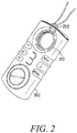
- FIG. 2 shows portable radio 100 wherein the through-hole 110 operates as a lanyard through which a rope 202, string, or similar device can be used.
- the through-hole 110 may also accommodate a belt clip.
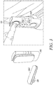
- FIG. 3 where the through-hole 110 receives belt clip 302.
- the belt clip 302 is formed to have a corresponding plug-in feature 304 which is insertable into the through-hole 110 and retained by the mechanical interface alignment feature 116.
- the through-hole 110 being circular provides the ability for the radio housing 102 to pivot easily on a belt to provide flexibility for wearing in various sitting or standing or mobile situations. The ability to plug the belt clip 302 into the through-hole 110 helps maintain a slim radio profile and minimize bulkiness.
- FIG. 4 shows an embodiment where the housing 102 comprises through-hole 110 having the electrical interface 114 and mechanical interface 116 on the interior wall of through-hole 110.
- the accessory shown in this embodiment comprises a connector for physical attachment 402 wired for electrical coupling to an audio accessory 406, such as earphones, ear buds or other type remote audio accessory.
- This configuration illustrates how the through-hole 110 is capable of accommodating both mechanical lanyard retention capability and electrical earphone interface capability at the same time.
- FIG. 5 shows a plurality of portable two-way radios, each numbered 100, and each having the through-hole 110 having the electrical and mechanical interface previously described.
- the through-hole 110 provides a mounting mechanism for charging the device.
- Corresponding alignment features 502 on the charging device 500 allows for a polarity of radio devices to be stacked, and for example hung from a wall mount 504.
- Corresponding electrical contacts on the (not shown) on the charger 500 align with the electrical interface features 114 of each radio 100.
- the through-hole 110 allows for multiple radios to be charged at one time.
- FIG. 6 shows the portable radio 100 comprising the through-hole 110 having the mechanical interface 116 and electrical interface 114 respectively providing a mounting mechanism and electrical coupling for a wireless earpiece 602.
- Wireless earpiece 602 includes a corresponding alignment feature 616, such as a ring, insert, tab, rib or other suitable alignment feature for aligning with mechanical interface alignment feature 116 of through-hole 110.
- Earpiece 602 further comprises a corresponding electrical interface feature 614, such as contacts, jacks, ports or other suitable feature for electrically coupling to the electrical interface 114 of through-hole 110.
- the electrical interface 114 of radio 100 can detect the removal of the wireless earpiece 602 via the separation of the electrical interface 114/614 to activate the wireless interconnect, such as a BLUETOOTH connection, between the two devices.
- the earpiece 602 which in the past might be easily misplaced due to its size, can now be safely stored in through-hole 110 via the interface alignment feature 116 and electrical interface 114.
- the electrical interface 114 of through-hole 110 can be formed of a plurality of different electrical contacts which align with different accessories based upon the physical mounting interface or the electrical contacts may be multiplexed by the radio to provide a plurality of different operational functions.
- the radio 100 detects the connection via electrical interface 114 and changes to high audio.
- the radio 100 detects the removal and changes the radio 100 to a muted condition and switches the audio to the earpiece, shown here as wireless but also applies to a wired earpiece.
- the through-hole 110 having a circular configuration is particularly advantageous as it allows for a variety of electrical and mechanical devices (and combinations of the two) to be accommodated.
- FIG. 7 shows the portable radio 100 comprising the through-hole 110 having the mechanical interface 116 and electrical interface 114 providing a mounting mechanism for a secondary battery pack 702.
- This embodiment shows the battery pack 702 having batteries 704 accessible via cover 706.
- the secondary battery pack 702 can be mounted via the through-hole 110 by aligning the alignment feature 716 with a corresponding alignment feature on the secondary battery pack and electrically coupling electrical contacts of the secondary battery pack 702 to the electrical interface 114.
- FIG. 8 shows another portable radio 800 formed in accordance with the various embodiments.
- the portable radio 800 such as a handheld two-way radio, comprises a housing 802 which comprises a push-to-talk (PTT) button 804, function keys 806, 808, and a display 809.
- PTT push-to-talk
- This embodiment is provided to show that alternative types of audio porting 812, such as audio holes can be used rather than grill porting.
- the function keys 806, 808 have been placed on the front surface of the housing 802, rather than the sides, again providing for a very thing, flat surface.
- the portable radio 800 similar to radio 100, comprises a through-hole 810 formed through the housing 802, the through-hole 810 providing an interface for coupling a plurality of interchangeable accessories through electrical interface features 814, such as contacts or other suitable electrical interface and mechanical interface alignment feature 816 in the manner previously described.
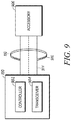
- FIG. 9 is a block diagram 900 of a portable radio having an accessory interface in accordance with the various embodiments.
- the portable radio 100 comprises a controller 902 and a transceiver 904 which provide radio communication, such as two-way radio communication.
- the portable radio 100 comprises a through-hole 110 formed therein, the through-hole providing the accessory interface.
- the through-hole 110 comprises mechanical interface feature(s) 912 and electrical interface feature(s) 914 to allow for the selective interchanging of a plurality of different accessories, represented here by accessory 906.
- the accessory may be an electrical accessory such as an earpiece, battery or charger, previously described, or other accessory formed to align within the through-hole.
- the through-hole may further accommodate non-electrical accessories (mechanical accessories) such as a belt clip or lanyard to name a few.
- the mechanical feature provides retention and removal of the accessory 906 having a corresponding alignment feature.
- the electrical feature may provide a plurality of electrical interfaces, either through different electrical contacts positioned within the through-hole 110 or through multiplexed contacts.
- the electrical interface is controlled via controller 902 of radio 100 to detect and control a plurality of different interchangeable accessories.
- the electrical interfaces may comprise for example, detecting the presence and absence of an accessory mounted within the through-hole 110 and adjusting the radio in response thereto.
- Portable radio communication devices such a portable two-way radio, formed in accordance with the various embodiments may incorporate a variety of diverse operating features, such as LTE, narrowband, Bluetooth, WLAN and as such the organization of the user interface is highly important. All of the embodiments a two-way portable radio having a slim profile, unencumbered by control knobs or an exterior antenna. While the user interface features have been highly integrated into this sleek profile device, the user interface is still very intuitive via the through-hole 110, the large PTT, and front function controls.
- the mechanical interface may comprise a snap-in / snap-out interface, a twist-in / twist-out interface provided by the alignment feature 116 of interior wall of the through-hole 110 thereby accommodating a variety of accessory devices to be coupled thereto without impacting the overall size or portability of the device.
- a portable two-way radio with improved user interface there has been provided a portable two-way radio with improved user interface.
- the housing formed in accordance with the various embodiments maintains a logistical user interface that accommodates interchangeable accessories through the use of an electro-mechanical through-hole 110 through the housing.
- Portable handheld radio products where a plurality of interchangeable interface features need to be incorporated within tight space constraints will benefit greatly from the housing provided by the various embodiments.
- the incorporation of a through-hole with accessory interface capability in accordance with the various embodiments allows for a radio to have smooth surfaces with minimal protrusions which facilitates the ability to carry the device in a pocket with or without the accessory.
Landscapes
- Engineering & Computer Science (AREA)
- Signal Processing (AREA)
- Computer Networks & Wireless Communication (AREA)
- Power Engineering (AREA)
- Telephone Set Structure (AREA)
- Casings For Electric Apparatus (AREA)
- Transceivers (AREA)
Description
- The present invention relates generally to communication devices and more particularly to communication devices that can accommodate a plurality of accessories.
- Communication devices, such as portable radios, are utilized in a wide variety of communication environments, such as business, consumer retail, security and the like. A portable, handheld radio is typically housed within a plastic enclosure, and depending on user interface requirements, the housing may offer a keypad, push-to-talk switch, control knobs, speaker grill and display. The desire to integrate additional features must be balanced with the ability to maintain a logistical user interface. Additionally, as more operating features are added to the radio, the ability to provide additional features within limited space constraints presents a challenge to designers. There is a strong desire to minimize protruding forms and in some use-cases it is highly desirable to have small products with smooth surfaces to aide in pocketability.
WO2009/089393 A1 (Aria Enterprises Inc) provides a modular, configurable, multi-function communication device. An information delivery module in the form of a circular 'puck' is provided. The puck has functional equipment such as a battery within it, and may have a display on a front surface and a camera on its rear surface. A beveled peripheral margin of the puck mates to a complementary depthwise tapered side surface of a separate information input module.EP1855507 A2 (LG Electronics Inc.) provides a communication device. A pair of detachable acoustic transducers may be located in the housing of the device. When located in the housing, both devices may function as speakers. However, one transducer may also function as a microphone, when a call is being made. When removed from the housing, both acoustic transducers may function as ear pieces. However, one of the transducers may again function as a microphone when a call is being made.WO02/093956 A1 - Accordingly, there is a need for an improved approach to providing additional user features to a housing of a portable communication device.
- In accordance with a first aspect of the invention, an apparatus comprising the features of appended claim 1 is provided. In accordance with a second aspect of the invention, a method comprising the steps of appended claim 9 is provided. The dependent claims provide further details of embodiments of the invention.
- The accompanying figures where like reference numerals refer to identical or functionally similar elements throughout the separate views and which together with the detailed description below are incorporated in and form part of the specification, serve to further illustrate various embodiments and to explain various principles and advantages all in accordance with the present invention.
-
FIG. 1 is a portable two-way radio formed in accordance with the various embodiments. -
FIG. 2 is the portable two-way radio in accordance with the various embodiments. -
FIG. 3 is the portable two-way radio in accordance with the various embodiments. -
FIG. 4 is the portable two-way radio in accordance with the various embodiments. -
FIG. 5 is the portable two-way radio in accordance with the various embodiments. -
FIG. 6 is the portable two-way radio in accordance with the various embodiments. -
FIG. 7 is the portable two-way radio in accordance with the various embodiments. -
FIG. 8 is a portable two-way radio in accordance with the various embodiments. -
FIG. 9 is a block diagram of a portable radio having an accessory interface in accordance with the various embodiments. - Skilled artisans will appreciate that elements in the figures are illustrated for simplicity and clarity and have not necessarily been drawn to scale. For example, the dimensions of some of the elements in the figures may be exaggerated relative to other elements to help to improve understanding of embodiments of the present invention.
- Before describing in detail embodiments that are in accordance with the present invention, it should be observed that the embodiments reside primarily in an improved housing for a two-way radio providing an accessory interface through-hole, the accessory interface through-hole being adaptable to a plurality of different accessories. The plurality of different accessories may be either electrical or mechanical or a combination of both. Accordingly, the components have been represented where appropriate by conventional symbols in the drawings, showing only those specific details that are pertinent to understanding the embodiments of the present invention so as not to obscure the disclosure with details that will be readily apparent to those of ordinary skill in the art having the benefit of the description herein.
- Briefly, there is provided herein a portable two-way radio housing which facilitates providing additional user interface features to a communication device by providing a radio housing having a through-hole within the housing, wherein the through-hole provides audio porting in conjunctions with a mechanical and electrical interface for accommodating different types of accessories.
- In this document, relational terms such as first and second, top and bottom, and the like may be used solely to distinguish one entity or action from another entity or action without necessarily requiring or implying any actual such relationship or order between such entities or actions. The terms "comprises," "comprising," or any other variation thereof, are intended to cover a non-exclusive inclusion, such that a process, method, article, or apparatus that comprises a list of elements does not include only those elements but may include other elements not expressly listed or inherent to such process, method, article, or apparatus. An element preceded by "comprises ... a" does not, without more constraints, preclude the existence of additional identical elements in the process, method, article, or apparatus that comprises the element.
-
FIG. 1 is aportable radio 100 formed in accordance with the various embodiments.FIGs. 2-7 show theportable t radio 100 operating with a variety of accessories in accordance with the various embodiments. Theportable radio 100 may be a portable two-way radio which comprises ahousing 102 having a push-to-talk (PTT)button 104 along with a plurality offunction keys display 109. Thefunction keys Portable radio 100 operates as a handheld device which is preferably sized to fit into the palm of a user and may further be carried in a pocket. - In accordance with the various embodiments,
housing 102 further comprises a through-hole 110. The through-hole 110 comprises a circular opening having aninterior wall 120 passing from a front surface of thehousing 102 to the back surface of the housing thereby forming a pass-through through the housing. The through-hole may be surrounded byaudio porting 112. In accordance with the various embodiments, disposed upon theinterior wall 120 of the through-hole 110 are electrical interface features 114 and a mechanicalinterface alignment feature 116. Theinterface alignment feature 116 may take the form of, for example a slot, a groove, a stop-bump or other alignment feature suitable to the space of theinterior wall 120. The electrical interface features may comprise contacts, plug, jack or other suitable electrical interface that can be accommodated within theinterior wall 120 of through-hole 110. In accordance with the various embodiments, the through-hole 110 provides a user interface that accommodates a variety of interchangeable accessory devices. - The
audio porting 112 surround the through-hole 110 and may be disposed on a sloped surface of thehousing 102 leading to theinterior wall 120 of the through-hole or may be disposed on a flat surface around the through-hole. Thefunction keys housing 102. ThePTT button 104 may be sized to align with the size of the through-hole with to give the user a balanced visual interface. Alternatively, thePTT button 104 could be placed on a different portion of the housing, such as the side. Thehousing 102 ofportable radio housing 100 is preferably formed of smooth surfaces and may be sized to carry in a pocket. -
FIG. 2 showsportable radio 100 wherein the through-hole 110 operates as a lanyard through which arope 202, string, or similar device can be used. For users who prefer to carry the device on his/her clothing, the through-hole 110 may also accommodate a belt clip. Such a configuration is shown inFIG. 3 where the through-hole 110 receivesbelt clip 302. Thebelt clip 302 is formed to have a corresponding plug-in feature 304 which is insertable into the through-hole 110 and retained by the mechanicalinterface alignment feature 116. The through-hole 110 being circular provides the ability for theradio housing 102 to pivot easily on a belt to provide flexibility for wearing in various sitting or standing or mobile situations. The ability to plug thebelt clip 302 into the through-hole 110 helps maintain a slim radio profile and minimize bulkiness. -
FIG. 4 shows an embodiment where thehousing 102 comprises through-hole 110 having theelectrical interface 114 andmechanical interface 116 on the interior wall of through-hole 110. The accessory shown in this embodiment comprises a connector for physical attachment 402 wired for electrical coupling to anaudio accessory 406, such as earphones, ear buds or other type remote audio accessory. This configuration illustrates how the through-hole 110 is capable of accommodating both mechanical lanyard retention capability and electrical earphone interface capability at the same time. -
FIG. 5 shows a plurality of portable two-way radios, each numbered 100, and each having the through-hole 110 having the electrical and mechanical interface previously described. In this embodiment, the through-hole 110 provides a mounting mechanism for charging the device. Corresponding alignment features 502 on thecharging device 500 allows for a polarity of radio devices to be stacked, and for example hung from awall mount 504. Corresponding electrical contacts on the (not shown) on thecharger 500 align with the electrical interface features 114 of eachradio 100. Thus the through-hole 110 allows for multiple radios to be charged at one time. -
FIG. 6 shows theportable radio 100 comprising the through-hole 110 having themechanical interface 116 andelectrical interface 114 respectively providing a mounting mechanism and electrical coupling for awireless earpiece 602.Wireless earpiece 602 includes acorresponding alignment feature 616, such as a ring, insert, tab, rib or other suitable alignment feature for aligning with mechanicalinterface alignment feature 116 of through-hole 110.Earpiece 602 further comprises a correspondingelectrical interface feature 614, such as contacts, jacks, ports or other suitable feature for electrically coupling to theelectrical interface 114 of through-hole 110. - The
electrical interface 114 ofradio 100 can detect the removal of thewireless earpiece 602 via the separation of theelectrical interface 114/614 to activate the wireless interconnect, such as a BLUETOOTH connection, between the two devices. Theearpiece 602, which in the past might be easily misplaced due to its size, can now be safely stored in through-hole 110 via theinterface alignment feature 116 andelectrical interface 114. - The
electrical interface 114 of through-hole 110 can be formed of a plurality of different electrical contacts which align with different accessories based upon the physical mounting interface or the electrical contacts may be multiplexed by the radio to provide a plurality of different operational functions. For example, when theearpiece 602 is coupled to the through-hole 110, theradio 100 detects the connection viaelectrical interface 114 and changes to high audio. Conversely, when theearpiece 602 is removed from the through-hole 110, theradio 100 detects the removal and changes theradio 100 to a muted condition and switches the audio to the earpiece, shown here as wireless but also applies to a wired earpiece. The through-hole 110 having a circular configuration is particularly advantageous as it allows for a variety of electrical and mechanical devices (and combinations of the two) to be accommodated. -
FIG. 7 shows theportable radio 100 comprising the through-hole 110 having themechanical interface 116 andelectrical interface 114 providing a mounting mechanism for asecondary battery pack 702. This embodiment shows thebattery pack 702 havingbatteries 704 accessible viacover 706. Thesecondary battery pack 702 can be mounted via the through-hole 110 by aligning thealignment feature 716 with a corresponding alignment feature on the secondary battery pack and electrically coupling electrical contacts of thesecondary battery pack 702 to theelectrical interface 114. -
FIG. 8 shows anotherportable radio 800 formed in accordance with the various embodiments. Theportable radio 800, such as a handheld two-way radio, comprises ahousing 802 which comprises a push-to-talk (PTT)button 804,function keys display 809. This embodiment is provided to show that alternative types of audio porting 812, such as audio holes can be used rather than grill porting. Thefunction keys housing 802, rather than the sides, again providing for a very thing, flat surface. Theportable radio 800, similar toradio 100, comprises a through-hole 810 formed through thehousing 802, the through-hole 810 providing an interface for coupling a plurality of interchangeable accessories through electrical interface features 814, such as contacts or other suitable electrical interface and mechanicalinterface alignment feature 816 in the manner previously described. -
FIG. 9 is a block diagram 900 of a portable radio having an accessory interface in accordance with the various embodiments. Theportable radio 100 comprises acontroller 902 and atransceiver 904 which provide radio communication, such as two-way radio communication. Theportable radio 100 comprises a through-hole 110 formed therein, the through-hole providing the accessory interface. The through-hole 110 comprises mechanical interface feature(s) 912 and electrical interface feature(s) 914 to allow for the selective interchanging of a plurality of different accessories, represented here byaccessory 906. The accessory may be an electrical accessory such as an earpiece, battery or charger, previously described, or other accessory formed to align within the through-hole. The through-hole may further accommodate non-electrical accessories (mechanical accessories) such as a belt clip or lanyard to name a few. - In accordance with the various embodiments, the mechanical feature provides retention and removal of the
accessory 906 having a corresponding alignment feature. The electrical feature may provide a plurality of electrical interfaces, either through different electrical contacts positioned within the through-hole 110 or through multiplexed contacts. The electrical interface is controlled viacontroller 902 ofradio 100 to detect and control a plurality of different interchangeable accessories. The electrical interfaces may comprise for example, detecting the presence and absence of an accessory mounted within the through-hole 110 and adjusting the radio in response thereto. - Portable radio communication devices, such a portable two-way radio, formed in accordance with the various embodiments may incorporate a variety of diverse operating features, such as LTE, narrowband, Bluetooth, WLAN and as such the organization of the user interface is highly important. All of the embodiments a two-way portable radio having a slim profile, unencumbered by control knobs or an exterior antenna. While the user interface features have been highly integrated into this sleek profile device, the user interface is still very intuitive via the through-
hole 110, the large PTT, and front function controls. The mechanical interface may comprise a snap-in / snap-out interface, a twist-in / twist-out interface provided by thealignment feature 116 of interior wall of the through-hole 110 thereby accommodating a variety of accessory devices to be coupled thereto without impacting the overall size or portability of the device. - Accordingly, in accordance with the various embodiments, there has been provided a portable two-way radio with improved user interface. The housing formed in accordance with the various embodiments maintains a logistical user interface that accommodates interchangeable accessories through the use of an electro-mechanical through-
hole 110 through the housing. Portable handheld radio products where a plurality of interchangeable interface features need to be incorporated within tight space constraints will benefit greatly from the housing provided by the various embodiments. The incorporation of a through-hole with accessory interface capability in accordance with the various embodiments allows for a radio to have smooth surfaces with minimal protrusions which facilitates the ability to carry the device in a pocket with or without the accessory. - In the foregoing specification, specific embodiments of the present invention have been described. However, one of ordinary skill in the art appreciates that various modifications and changes can be made without departing from the scope of the present invention as set forth in the claims below. Accordingly, the specification and figures are to be regarded in an illustrative rather than a restrictive sense, and all such modifications are intended to be included within the scope of present invention. The benefits, advantages, solutions to problems, and any element(s) that may cause any benefit, advantage, or solution to occur or become more pronounced are not to be construed as a critical, required, or essential features or elements of any or all the claims. The invention is defined solely by the appended claims including any amendments made during the pendency of this application and all equivalents of those claims as issued.
Claims (14)
- A portable radio (100), comprising:a housing (102) having a through-hole (110);the through-hole (110) providing an electrical interface feature (114) and a mechanical interface feature (116) for coupling a plurality of interchangeable accessories; andaudio porting (112; 812) disposed on the housing surrounding the through-hole.
- The portable radio (100) of claim 1, wherein the through-hole (110) is circular.
- The portable radio (100) of claim 1, wherein the through-hole (110) has an interior wall (120) formed from a front side of the housing (102) to a back side of the housing (102), the interior wall (120) having the electrical interface feature (114) and the mechanical interface feature (116) disposed thereon for coupling to the plurality of interchangeable accessories.
- The portable radio (100) of claim 1, wherein the electrical interface feature (114) is adapted to detect a presence and an absence of an accessory mounted within the mechanical interface (116) of the through-hole (110), and the portable radio (100) is adapted to adjust operation in response thereto.
- The portable radio (100) of claim 3, wherein the housing (102) comprises a controller for controlling the electrical interface feature (114) and operation of the plurality of interchangeable accessories.
- The portable radio (100) of claim 1, wherein the through-hole (110) within the housing (102) interchangeably accommodates two or more of: a belt clip (302), an earpiece (406), a speaker, a charger interface (500), a lanyard, and a battery pack (702).
- The portable radio (100) of claim 1, wherein the through-hole (110) provides an electro-mechanical interface.
- The portable radio (100) of claim 1, wherein the through-hole (110) provides an interface having both mechanical lanyard retention capability and electrical earphone interface capability at the same time.
- A method for providing an accessory interface in a portable radio (100), comprising:providing a portable radio housing (102) having a through-hole (110) formed therein, the through-hole (110) providing the accessory interface, the through-hole (110) comprising an electrical interface feature (114) and a mechanical interface feature (116) for selectively interchanging a plurality of different accessories, and audio porting (112; 812) disposed on the portable radio housing surrounding the through-hole (110).
- The method of claim 9 further comprising, providing, by the mechanical interface feature (116), retention and removal of each of the plurality of different accessories, each accessory having a corresponding alignment feature.
- The method of claim 9, wherein the electrical interface feature (114) comprises electrical contacts for charging the portable radio (100).
- The method of claim 9 further comprising, detecting, by the electrical interface feature (114), a presence and an absence of an accessory via a controller (902) within the portable radio (100).
- The method of claim 9, wherein the electrical interface feature (114) is multiplexed for operating with a plurality of different interchangeable accessories.
- The method of claim 9, further comprising, providing, by the mechanical interface (116), a twist-in and twist-out alignment feature or a snap-in and snap-out alignment feature.
Applications Claiming Priority (2)
| Application Number | Priority Date | Filing Date | Title |
|---|---|---|---|
| US13/778,452 US9042846B2 (en) | 2013-02-27 | 2013-02-27 | Portable radio having accessory interface |
| PCT/US2014/016674 WO2014133800A1 (en) | 2013-02-27 | 2014-02-17 | Portable radio having accessory interface |
Publications (2)
| Publication Number | Publication Date |
|---|---|
| EP2962447A1 EP2962447A1 (en) | 2016-01-06 |
| EP2962447B1 true EP2962447B1 (en) | 2017-08-09 |
Family
ID=50277298
Family Applications (1)
| Application Number | Title | Priority Date | Filing Date |
|---|---|---|---|
| EP14710083.8A Active EP2962447B1 (en) | 2013-02-27 | 2014-02-17 | Portable radio having accessory interface |
Country Status (6)
| Country | Link |
|---|---|
| US (1) | US9042846B2 (en) |
| EP (1) | EP2962447B1 (en) |
| CN (1) | CN105191264B (en) |
| AU (1) | AU2014223934B2 (en) |
| CA (1) | CA2900389C (en) |
| WO (1) | WO2014133800A1 (en) |
Families Citing this family (6)
| Publication number | Priority date | Publication date | Assignee | Title |
|---|---|---|---|---|
| US9407313B2 (en) * | 2014-07-31 | 2016-08-02 | Motorola Solutions, Inc. | Radio housing having through-hole connector for coupling accessories |
| US9301047B2 (en) | 2014-08-29 | 2016-03-29 | Motorola Solutions, Inc. | Loudspeaker audio accessory for a communication device |
| US10230255B2 (en) | 2015-10-07 | 2019-03-12 | Motorola Solutions, Inc. | Apparatus, method and system for providing expanded functionality to communication devices using wireless charging coil-in-coil |
| ES3055343T3 (en) * | 2018-08-03 | 2026-02-11 | Ryan Joseph Murphey | Wearable power supply system |
| US10651880B1 (en) | 2019-09-30 | 2020-05-12 | Motorola Solutions, Inc. | Portable radio with external antenna cover and lanyard through-hole feature |
| CN120240786A (en) * | 2024-01-03 | 2025-07-04 | 佳音医疗器材股份有限公司 | Anti-lost rope and anti-lost device |
Family Cites Families (12)
| Publication number | Priority date | Publication date | Assignee | Title |
|---|---|---|---|---|
| JP3417105B2 (en) | 1994-12-12 | 2003-06-16 | ソニー株式会社 | Electronics |
| ATE250828T1 (en) | 2000-12-22 | 2003-10-15 | Ericsson Telefon Ab L M | ELECTRONIC DEVICE FOR A MOBILE RADIO STATION |
| US6721545B2 (en) * | 2001-05-17 | 2004-04-13 | Wildseed, Ltd. | Mobile electronic communication device and covering for similar devices with ornament attachment mechanism |
| KR100575998B1 (en) * | 2002-04-12 | 2006-05-02 | 삼성전자주식회사 | Portable wireless terminal |
| KR100998409B1 (en) * | 2002-07-31 | 2010-12-03 | 파나소닉 주식회사 | Handheld wireless communication device |
| KR100739564B1 (en) | 2003-07-31 | 2007-07-16 | 엘지전자 주식회사 | Mobile terminal with camera |
| TWI304300B (en) | 2005-08-30 | 2008-12-11 | Asustek Comp Inc | Mobile device having a digital camera and an assembling method for a decoration ring |
| US20070099593A1 (en) | 2005-11-02 | 2007-05-03 | Timothy Thome | Method for managing interchangeable accessory modules connected to a portable communication device |
| KR101128170B1 (en) | 2006-05-10 | 2012-03-23 | 엘지전자 주식회사 | Portable terminal having acoustic transducer and the control method |
| CA2712252A1 (en) * | 2008-01-10 | 2009-07-16 | Aria Enterprises, Inc. | Customizable modular multi-function communication device |
| JP5375831B2 (en) | 2009-02-18 | 2013-12-25 | パナソニック株式会社 | Receiver |
| JP5651974B2 (en) | 2010-03-26 | 2015-01-14 | 富士通株式会社 | Mobile terminal device |
-
2013
- 2013-02-27 US US13/778,452 patent/US9042846B2/en active Active
-
2014
- 2014-02-17 EP EP14710083.8A patent/EP2962447B1/en active Active
- 2014-02-17 CN CN201480009383.7A patent/CN105191264B/en active Active
- 2014-02-17 WO PCT/US2014/016674 patent/WO2014133800A1/en not_active Ceased
- 2014-02-17 CA CA2900389A patent/CA2900389C/en active Active
- 2014-02-17 AU AU2014223934A patent/AU2014223934B2/en active Active
Non-Patent Citations (1)
| Title |
|---|
| None * |
Also Published As
| Publication number | Publication date |
|---|---|
| CA2900389A1 (en) | 2014-09-04 |
| US9042846B2 (en) | 2015-05-26 |
| CN105191264A (en) | 2015-12-23 |
| US20140242928A1 (en) | 2014-08-28 |
| AU2014223934A1 (en) | 2015-08-20 |
| AU2014223934B2 (en) | 2016-03-03 |
| EP2962447A1 (en) | 2016-01-06 |
| CA2900389C (en) | 2017-11-21 |
| CN105191264B (en) | 2018-11-09 |
| WO2014133800A1 (en) | 2014-09-04 |
Similar Documents
| Publication | Publication Date | Title |
|---|---|---|
| US10104463B2 (en) | Wireless sound equipment | |
| CN108184184B (en) | bluetooth earphone | |
| US9172070B2 (en) | Battery pack, holster, and extendible processing and interface platform for mobile devices | |
| US11039238B2 (en) | Wireless earbud charging and communication systems and methods | |
| CA2900389C (en) | Portable radio having accessory interface | |
| EP3142195A1 (en) | Earphone seat | |
| CN212115613U (en) | headphone system | |
| US9369558B2 (en) | Hands-free communication devices for corded and wireless communication | |
| KR20140035742A (en) | Bluetooth headset | |
| CN208079064U (en) | Talk back equipment with earphone | |
| TW201628416A (en) | Earphone module | |
| CN103248978A (en) | Wireless adapter and wireless earphone | |
| EP4087219A1 (en) | Electronic device | |
| TWI275287B (en) | Bluetooth mobile phone having a detachable bluetooth earpiece | |
| KR20160147498A (en) | Detachable mono earset | |
| EP2773085B1 (en) | Holding platform for mobile information terminals, desktop telephone, and fixing method for connector for mobile information terminals | |
| CN211152206U (en) | Accessory, terminal host and terminal | |
| US20130049672A1 (en) | Mobile Telephone Wireless Earpiece Storage and Charging Device | |
| EP2299661A2 (en) | Electronic device for accommodating an earphone | |
| CN104598853B (en) | Card protective sleeve with electronic equipment function | |
| CN210724888U (en) | Wireless talkback functional mobile phone | |
| WO2017197755A1 (en) | Wireless headphone and terminal | |
| KR20100018380A (en) | Mobile communication device | |
| KR101515039B1 (en) | Mobile device case | |
| CN107920144A (en) | A kind of mobile phone |
Legal Events
| Date | Code | Title | Description |
|---|---|---|---|
| PUAI | Public reference made under article 153(3) epc to a published international application that has entered the european phase |
Free format text: ORIGINAL CODE: 0009012 |
|
| 17P | Request for examination filed |
Effective date: 20150928 |
|
| AK | Designated contracting states |
Kind code of ref document: A1 Designated state(s): AL AT BE BG CH CY CZ DE DK EE ES FI FR GB GR HR HU IE IS IT LI LT LU LV MC MK MT NL NO PL PT RO RS SE SI SK SM TR |
|
| AX | Request for extension of the european patent |
Extension state: BA ME |
|
| DAX | Request for extension of the european patent (deleted) | ||
| RAP1 | Party data changed (applicant data changed or rights of an application transferred) |
Owner name: MOTOROLA SOLUTIONS, INC. |
|
| GRAP | Despatch of communication of intention to grant a patent |
Free format text: ORIGINAL CODE: EPIDOSNIGR1 |
|
| INTG | Intention to grant announced |
Effective date: 20170323 |
|
| GRAS | Grant fee paid |
Free format text: ORIGINAL CODE: EPIDOSNIGR3 |
|
| GRAA | (expected) grant |
Free format text: ORIGINAL CODE: 0009210 |
|
| AK | Designated contracting states |
Kind code of ref document: B1 Designated state(s): AL AT BE BG CH CY CZ DE DK EE ES FI FR GB GR HR HU IE IS IT LI LT LU LV MC MK MT NL NO PL PT RO RS SE SI SK SM TR |
|
| REG | Reference to a national code |
Ref country code: GB Ref legal event code: FG4D |
|
| REG | Reference to a national code |
Ref country code: CH Ref legal event code: EP Ref country code: AT Ref legal event code: REF Ref document number: 917984 Country of ref document: AT Kind code of ref document: T Effective date: 20170815 |
|
| REG | Reference to a national code |
Ref country code: IE Ref legal event code: FG4D |
|
| REG | Reference to a national code |
Ref country code: DE Ref legal event code: R096 Ref document number: 602014012828 Country of ref document: DE |
|
| REG | Reference to a national code |
Ref country code: NL Ref legal event code: MP Effective date: 20170809 |
|
| REG | Reference to a national code |
Ref country code: LT Ref legal event code: MG4D |
|
| REG | Reference to a national code |
Ref country code: AT Ref legal event code: MK05 Ref document number: 917984 Country of ref document: AT Kind code of ref document: T Effective date: 20170809 |
|
| PG25 | Lapsed in a contracting state [announced via postgrant information from national office to epo] |
Ref country code: HR Free format text: LAPSE BECAUSE OF FAILURE TO SUBMIT A TRANSLATION OF THE DESCRIPTION OR TO PAY THE FEE WITHIN THE PRESCRIBED TIME-LIMIT Effective date: 20170809 Ref country code: LT Free format text: LAPSE BECAUSE OF FAILURE TO SUBMIT A TRANSLATION OF THE DESCRIPTION OR TO PAY THE FEE WITHIN THE PRESCRIBED TIME-LIMIT Effective date: 20170809 Ref country code: AT Free format text: LAPSE BECAUSE OF FAILURE TO SUBMIT A TRANSLATION OF THE DESCRIPTION OR TO PAY THE FEE WITHIN THE PRESCRIBED TIME-LIMIT Effective date: 20170809 Ref country code: FI Free format text: LAPSE BECAUSE OF FAILURE TO SUBMIT A TRANSLATION OF THE DESCRIPTION OR TO PAY THE FEE WITHIN THE PRESCRIBED TIME-LIMIT Effective date: 20170809 Ref country code: NO Free format text: LAPSE BECAUSE OF FAILURE TO SUBMIT A TRANSLATION OF THE DESCRIPTION OR TO PAY THE FEE WITHIN THE PRESCRIBED TIME-LIMIT Effective date: 20171109 Ref country code: SE Free format text: LAPSE BECAUSE OF FAILURE TO SUBMIT A TRANSLATION OF THE DESCRIPTION OR TO PAY THE FEE WITHIN THE PRESCRIBED TIME-LIMIT Effective date: 20170809 Ref country code: NL Free format text: LAPSE BECAUSE OF FAILURE TO SUBMIT A TRANSLATION OF THE DESCRIPTION OR TO PAY THE FEE WITHIN THE PRESCRIBED TIME-LIMIT Effective date: 20170809 |
|
| REG | Reference to a national code |
Ref country code: FR Ref legal event code: PLFP Year of fee payment: 5 |
|
| PG25 | Lapsed in a contracting state [announced via postgrant information from national office to epo] |
Ref country code: GR Free format text: LAPSE BECAUSE OF FAILURE TO SUBMIT A TRANSLATION OF THE DESCRIPTION OR TO PAY THE FEE WITHIN THE PRESCRIBED TIME-LIMIT Effective date: 20171110 Ref country code: LV Free format text: LAPSE BECAUSE OF FAILURE TO SUBMIT A TRANSLATION OF THE DESCRIPTION OR TO PAY THE FEE WITHIN THE PRESCRIBED TIME-LIMIT Effective date: 20170809 Ref country code: PL Free format text: LAPSE BECAUSE OF FAILURE TO SUBMIT A TRANSLATION OF THE DESCRIPTION OR TO PAY THE FEE WITHIN THE PRESCRIBED TIME-LIMIT Effective date: 20170809 Ref country code: IS Free format text: LAPSE BECAUSE OF FAILURE TO SUBMIT A TRANSLATION OF THE DESCRIPTION OR TO PAY THE FEE WITHIN THE PRESCRIBED TIME-LIMIT Effective date: 20171209 Ref country code: ES Free format text: LAPSE BECAUSE OF FAILURE TO SUBMIT A TRANSLATION OF THE DESCRIPTION OR TO PAY THE FEE WITHIN THE PRESCRIBED TIME-LIMIT Effective date: 20170809 Ref country code: RS Free format text: LAPSE BECAUSE OF FAILURE TO SUBMIT A TRANSLATION OF THE DESCRIPTION OR TO PAY THE FEE WITHIN THE PRESCRIBED TIME-LIMIT Effective date: 20170809 Ref country code: BG Free format text: LAPSE BECAUSE OF FAILURE TO SUBMIT A TRANSLATION OF THE DESCRIPTION OR TO PAY THE FEE WITHIN THE PRESCRIBED TIME-LIMIT Effective date: 20171109 |
|
| PG25 | Lapsed in a contracting state [announced via postgrant information from national office to epo] |
Ref country code: RO Free format text: LAPSE BECAUSE OF FAILURE TO SUBMIT A TRANSLATION OF THE DESCRIPTION OR TO PAY THE FEE WITHIN THE PRESCRIBED TIME-LIMIT Effective date: 20170809 Ref country code: CZ Free format text: LAPSE BECAUSE OF FAILURE TO SUBMIT A TRANSLATION OF THE DESCRIPTION OR TO PAY THE FEE WITHIN THE PRESCRIBED TIME-LIMIT Effective date: 20170809 Ref country code: DK Free format text: LAPSE BECAUSE OF FAILURE TO SUBMIT A TRANSLATION OF THE DESCRIPTION OR TO PAY THE FEE WITHIN THE PRESCRIBED TIME-LIMIT Effective date: 20170809 |
|
| REG | Reference to a national code |
Ref country code: DE Ref legal event code: R097 Ref document number: 602014012828 Country of ref document: DE |
|
| PG25 | Lapsed in a contracting state [announced via postgrant information from national office to epo] |
Ref country code: SK Free format text: LAPSE BECAUSE OF FAILURE TO SUBMIT A TRANSLATION OF THE DESCRIPTION OR TO PAY THE FEE WITHIN THE PRESCRIBED TIME-LIMIT Effective date: 20170809 Ref country code: IT Free format text: LAPSE BECAUSE OF FAILURE TO SUBMIT A TRANSLATION OF THE DESCRIPTION OR TO PAY THE FEE WITHIN THE PRESCRIBED TIME-LIMIT Effective date: 20170809 Ref country code: EE Free format text: LAPSE BECAUSE OF FAILURE TO SUBMIT A TRANSLATION OF THE DESCRIPTION OR TO PAY THE FEE WITHIN THE PRESCRIBED TIME-LIMIT Effective date: 20170809 Ref country code: SM Free format text: LAPSE BECAUSE OF FAILURE TO SUBMIT A TRANSLATION OF THE DESCRIPTION OR TO PAY THE FEE WITHIN THE PRESCRIBED TIME-LIMIT Effective date: 20170809 |
|
| PLBE | No opposition filed within time limit |
Free format text: ORIGINAL CODE: 0009261 |
|
| STAA | Information on the status of an ep patent application or granted ep patent |
Free format text: STATUS: NO OPPOSITION FILED WITHIN TIME LIMIT |
|
| 26N | No opposition filed |
Effective date: 20180511 |
|
| PG25 | Lapsed in a contracting state [announced via postgrant information from national office to epo] |
Ref country code: SI Free format text: LAPSE BECAUSE OF FAILURE TO SUBMIT A TRANSLATION OF THE DESCRIPTION OR TO PAY THE FEE WITHIN THE PRESCRIBED TIME-LIMIT Effective date: 20170809 |
|
| REG | Reference to a national code |
Ref country code: CH Ref legal event code: PL |
|
| PG25 | Lapsed in a contracting state [announced via postgrant information from national office to epo] |
Ref country code: MC Free format text: LAPSE BECAUSE OF FAILURE TO SUBMIT A TRANSLATION OF THE DESCRIPTION OR TO PAY THE FEE WITHIN THE PRESCRIBED TIME-LIMIT Effective date: 20170809 |
|
| REG | Reference to a national code |
Ref country code: IE Ref legal event code: MM4A |
|
| REG | Reference to a national code |
Ref country code: BE Ref legal event code: MM Effective date: 20180228 |
|
| PG25 | Lapsed in a contracting state [announced via postgrant information from national office to epo] |
Ref country code: CH Free format text: LAPSE BECAUSE OF NON-PAYMENT OF DUE FEES Effective date: 20180228 Ref country code: LU Free format text: LAPSE BECAUSE OF NON-PAYMENT OF DUE FEES Effective date: 20180217 Ref country code: LI Free format text: LAPSE BECAUSE OF NON-PAYMENT OF DUE FEES Effective date: 20180228 |
|
| PG25 | Lapsed in a contracting state [announced via postgrant information from national office to epo] |
Ref country code: IE Free format text: LAPSE BECAUSE OF NON-PAYMENT OF DUE FEES Effective date: 20180217 |
|
| PG25 | Lapsed in a contracting state [announced via postgrant information from national office to epo] |
Ref country code: BE Free format text: LAPSE BECAUSE OF NON-PAYMENT OF DUE FEES Effective date: 20180228 |
|
| PG25 | Lapsed in a contracting state [announced via postgrant information from national office to epo] |
Ref country code: MT Free format text: LAPSE BECAUSE OF NON-PAYMENT OF DUE FEES Effective date: 20180217 |
|
| PG25 | Lapsed in a contracting state [announced via postgrant information from national office to epo] |
Ref country code: TR Free format text: LAPSE BECAUSE OF FAILURE TO SUBMIT A TRANSLATION OF THE DESCRIPTION OR TO PAY THE FEE WITHIN THE PRESCRIBED TIME-LIMIT Effective date: 20170809 |
|
| PG25 | Lapsed in a contracting state [announced via postgrant information from national office to epo] |
Ref country code: PT Free format text: LAPSE BECAUSE OF FAILURE TO SUBMIT A TRANSLATION OF THE DESCRIPTION OR TO PAY THE FEE WITHIN THE PRESCRIBED TIME-LIMIT Effective date: 20170809 |
|
| PG25 | Lapsed in a contracting state [announced via postgrant information from national office to epo] |
Ref country code: HU Free format text: LAPSE BECAUSE OF FAILURE TO SUBMIT A TRANSLATION OF THE DESCRIPTION OR TO PAY THE FEE WITHIN THE PRESCRIBED TIME-LIMIT; INVALID AB INITIO Effective date: 20140217 Ref country code: CY Free format text: LAPSE BECAUSE OF FAILURE TO SUBMIT A TRANSLATION OF THE DESCRIPTION OR TO PAY THE FEE WITHIN THE PRESCRIBED TIME-LIMIT Effective date: 20170809 Ref country code: MK Free format text: LAPSE BECAUSE OF NON-PAYMENT OF DUE FEES Effective date: 20170809 |
|
| PG25 | Lapsed in a contracting state [announced via postgrant information from national office to epo] |
Ref country code: AL Free format text: LAPSE BECAUSE OF FAILURE TO SUBMIT A TRANSLATION OF THE DESCRIPTION OR TO PAY THE FEE WITHIN THE PRESCRIBED TIME-LIMIT Effective date: 20170809 |
|
| P01 | Opt-out of the competence of the unified patent court (upc) registered |
Effective date: 20230523 |
|
| REG | Reference to a national code |
Ref country code: DE Ref legal event code: R082 Ref document number: 602014012828 Country of ref document: DE Representative=s name: PUSCHMANN BORCHERT KAISER KLETTNER PATENTANWAE, DE Ref country code: DE Ref legal event code: R082 Ref document number: 602014012828 Country of ref document: DE Representative=s name: PATCARE PATENTANWAELTE PARTNERSCHAFT MBB, DE |
|
| PGFP | Annual fee paid to national office [announced via postgrant information from national office to epo] |
Ref country code: GB Payment date: 20260121 Year of fee payment: 13 |
|
| PGFP | Annual fee paid to national office [announced via postgrant information from national office to epo] |
Ref country code: DE Payment date: 20260121 Year of fee payment: 13 |
|
| PGFP | Annual fee paid to national office [announced via postgrant information from national office to epo] |
Ref country code: FR Payment date: 20260121 Year of fee payment: 13 |