EP2962048B1 - Device to regulate the relative humidity level in a cpv module - Google Patents
Device to regulate the relative humidity level in a cpv module Download PDFInfo
- Publication number
- EP2962048B1 EP2962048B1 EP14705032.2A EP14705032A EP2962048B1 EP 2962048 B1 EP2962048 B1 EP 2962048B1 EP 14705032 A EP14705032 A EP 14705032A EP 2962048 B1 EP2962048 B1 EP 2962048B1
- Authority
- EP
- European Patent Office
- Prior art keywords
- module
- outside
- unit
- temperature
- relative humidity
- Prior art date
- Legal status (The legal status is an assumption and is not a legal conclusion. Google has not performed a legal analysis and makes no representation as to the accuracy of the status listed.)
- Not-in-force
Links
Images




Classifications
-
- F—MECHANICAL ENGINEERING; LIGHTING; HEATING; WEAPONS; BLASTING
- F24—HEATING; RANGES; VENTILATING
- F24S—SOLAR HEAT COLLECTORS; SOLAR HEAT SYSTEMS
- F24S40/00—Safety or protection arrangements of solar heat collectors; Preventing malfunction of solar heat collectors
- F24S40/40—Preventing corrosion; Protecting against dirt or contamination
- F24S40/42—Preventing condensation inside solar modules
-
- F—MECHANICAL ENGINEERING; LIGHTING; HEATING; WEAPONS; BLASTING
- F24—HEATING; RANGES; VENTILATING
- F24S—SOLAR HEAT COLLECTORS; SOLAR HEAT SYSTEMS
- F24S40/00—Safety or protection arrangements of solar heat collectors; Preventing malfunction of solar heat collectors
- F24S40/50—Preventing overheating or overpressure
- F24S40/57—Preventing overpressure in solar collector enclosures
-
- H—ELECTRICITY
- H02—GENERATION; CONVERSION OR DISTRIBUTION OF ELECTRIC POWER
- H02S—GENERATION OF ELECTRIC POWER BY CONVERSION OF INFRARED RADIATION, VISIBLE LIGHT OR ULTRAVIOLET LIGHT, e.g. USING PHOTOVOLTAIC [PV] MODULES
- H02S40/00—Components or accessories in combination with PV modules, not provided for in groups H02S10/00 - H02S30/00
-
- Y—GENERAL TAGGING OF NEW TECHNOLOGICAL DEVELOPMENTS; GENERAL TAGGING OF CROSS-SECTIONAL TECHNOLOGIES SPANNING OVER SEVERAL SECTIONS OF THE IPC; TECHNICAL SUBJECTS COVERED BY FORMER USPC CROSS-REFERENCE ART COLLECTIONS [XRACs] AND DIGESTS
- Y02—TECHNOLOGIES OR APPLICATIONS FOR MITIGATION OR ADAPTATION AGAINST CLIMATE CHANGE
- Y02E—REDUCTION OF GREENHOUSE GAS [GHG] EMISSIONS, RELATED TO ENERGY GENERATION, TRANSMISSION OR DISTRIBUTION
- Y02E10/00—Energy generation through renewable energy sources
- Y02E10/40—Solar thermal energy, e.g. solar towers
-
- Y—GENERAL TAGGING OF NEW TECHNOLOGICAL DEVELOPMENTS; GENERAL TAGGING OF CROSS-SECTIONAL TECHNOLOGIES SPANNING OVER SEVERAL SECTIONS OF THE IPC; TECHNICAL SUBJECTS COVERED BY FORMER USPC CROSS-REFERENCE ART COLLECTIONS [XRACs] AND DIGESTS
- Y02—TECHNOLOGIES OR APPLICATIONS FOR MITIGATION OR ADAPTATION AGAINST CLIMATE CHANGE
- Y02E—REDUCTION OF GREENHOUSE GAS [GHG] EMISSIONS, RELATED TO ENERGY GENERATION, TRANSMISSION OR DISTRIBUTION
- Y02E10/00—Energy generation through renewable energy sources
- Y02E10/50—Photovoltaic [PV] energy
-
- Y—GENERAL TAGGING OF NEW TECHNOLOGICAL DEVELOPMENTS; GENERAL TAGGING OF CROSS-SECTIONAL TECHNOLOGIES SPANNING OVER SEVERAL SECTIONS OF THE IPC; TECHNICAL SUBJECTS COVERED BY FORMER USPC CROSS-REFERENCE ART COLLECTIONS [XRACs] AND DIGESTS
- Y02—TECHNOLOGIES OR APPLICATIONS FOR MITIGATION OR ADAPTATION AGAINST CLIMATE CHANGE
- Y02E—REDUCTION OF GREENHOUSE GAS [GHG] EMISSIONS, RELATED TO ENERGY GENERATION, TRANSMISSION OR DISTRIBUTION
- Y02E10/00—Energy generation through renewable energy sources
- Y02E10/50—Photovoltaic [PV] energy
- Y02E10/52—PV systems with concentrators
Definitions
- the present invention generally relates to a device and a method for regulating the relative humidity level inside a solar cell module.
- the device and the method are particularly well suited for concentrator photovoltaic (CPV) modules.
- CPV concentrator photovoltaic
- CPV modules the incident light, in particular the solar radiation, is concentrated on a photovoltaic cell by an optical system comprising, e.g., a mirror or a lens, such as a Fresnel lens or a spherical lens.
- the cell is thereby positioned at the focus of the lens.
- CPV modules are mounted, alone or combined in arrays, on tracking units in order to be optimally oriented towards the incident light, in particular following the brightest region in the sky.
- CPV modules should be sealed completely to avoid degrading of the solar cells and other electrical components, e.g. the bypass diodes or the electrical wiring, due to environmental influences.
- an elevated level of relative humidity in the module which can cause under certain circumstances condensation of water vapor on the components situated inside the module.
- an adsorber or desiccant unit is connected to the module which role is to dry the incoming air.
- Adsorption is a phenomenon leading to the physico-chemical fixation of molecules of water vapor on the surface of a solid, in particular an adsorber or desiccant material, as for instance a silica gel which is characterized by a high porosity.
- Moist air from outside the module is blown with a fan through the adsorber unit, in particular containing as adsorber material a silica gel, which absorbs excess moisture, and dried air is sent directly to the CPV modules.
- the adsorbent becomes saturated and must be regenerated to remove moisture.
- This regeneration generally takes place when the relative humidity measured after the adsorbent unit is above a certain limit, and the regeneration duration depends on this relative humidity level. This regeneration is ensured by the passage of air heated to a temperature above 60 °C and the moist hot air has to be evacuated outside.
- This regeneration phase is highly energy consuming and needs an active device assuring the flow of air, in particular a fan. Moreover, lack of supervisory control and communication leads to an unnecessary use of the drying unit, even when the outside meteorological conditions are optimal to avoid to dry modules, in particular elevated outside temperature and low relative humidity outside the module.
- the objective of the invention is to propose a device and a process for regulating the relative humidity level inside a solar cell module obviating the above-mentioned detriments.
- the present invention relates to a device according to claim 1 to regulate the relative humidity level in a CPV module.
- This regulation enables one to limit the use of the desiccant unit and, thus, reduce energy consumption due to the regeneration phase and also, by decreasing the use of the desiccant unit, one prevents precipitate saturation of the latter.
- By adjusting the capacity of the desiccant unit it is possible to create a self-correcting and maintenance free humidity regulation unit for a CPV system containing at least one module.
- the regulation unit of the humidity regulating device comprises at least a sensor adapted to measure physical values with reference to the inside of the module or at least a sensor adapted to measure physical values with reference to the outside of the module, and in which the regulation unit records and compares the measures with predetermined thresholds to actuate the switching mechanism.
- the regulation unit of the humidity regulating device comprises at least a sensor adapted to measure physical values with reference to the inside of the module and at least a sensor adapted to measure physical values with reference to the outside of the module, and in which the regulation unit records and compares their measures to actuate the switching mechanism.
- the physical values measured can respectively be the temperature, relative humidity, and pressure, inside and outside the module.
- the module of the humidity regulating device is connected to ambient atmosphere via a second duct connected to said first duct at an intersection, the switching mechanism comprising a first valve placed on the first duct between the desiccant unit and the intersection, and comprising a second valve placed on the second duct between the intersection and the ambient atmosphere.
- the module of the humidity regulating device is connected to ambient atmosphere via a second duct connected to said first duct at an intersection, the switching mechanism comprising a L-valve placed at the intersection.
- the module of the humidity regulating device is connected to ambient atmosphere via an opening placed on the module, the switching mechanism comprising valves placed on the first duct and the opening.
- the humidity regulating device further comprises a non-return membrane place on at least one of the module units able to evacuate overpressure from inside the module to ambient atmosphere.
- the humidity regulating device allows the gas flow between the module and the desiccant unit when the regulation unit records a pressure in the module inferior to the pressure outside the module and the temperature inside or outside the module is lower than the predetermined temperature threshold and/or the relative humidity inside or outside the module is higher than the predetermined relative humidity threshold.
- the humidity regulating device allows the gas flow between the module and ambient atmosphere when the regulation unit records a pressure in the module inferior to the pressure outside the module and the temperature inside or outside the module is higher than the predetermined temperature threshold and/or the relative humidity inside or outside the module is lower than the predetermined relative humidity threshold.
- the humidity regulating device allows the gas flow between the module and the desiccant unit when the regulation unit records a pressure in the module inferior to the pressure outside the module and a temperature outside the module which is approaching the dew point temperature inside the module, the dew point being calculated from the measure of the temperature and relative humidity inside the module, from higher temperatures by less than a predetermined threshold, preferentially 2°C.
- the humidity regulating device allows the gas flow between the module and the ambient atmosphere when the regulation unit records a pressure in the module inferior to the pressure outside the module and the outside temperature is exceeding the dew point temperature inside the module, the dew point being calculated from the measure of the temperature and relative humidity inside the module, by more than a predetermined threshold, preferentially 2°C.
- the desiccant unit is not used and gas flow to the module, induced by the depression in the module, is allowed when the meteorological conditions are favorable, in particular the temperature outside the module is higher than the dew point temperature plus a predetermined threshold, in particular 2°C.
- a predetermined threshold in particular 2°C.
- the humidity regulating device allows the gas flow between the module and the ambient atmosphere when the regulation unit records a pressure in the module superior to the pressure outside the module.
- the humidity regulating device allows the gas flow between the module and the desiccant unit when the regulation unit records a pressure in the module inferior to the pressure outside the module and the outside temperature is exceeding the dew point temperature inside the module, the dew point being calculated from the measure of the temperature and relative humidity inside the module, by more than a predetermined threshold, preferentially 2°C, and the relative humidity level outside the module exceeds a predetermined threshold, preferentially 70%.
- the humidity regulating device allows the gas flow between the module and the ambient atmosphere when the regulation unit records a pressure in the module inferior to the pressure outside the module and the outside temperature is exceeding the dew point temperature inside the module, the dew point being calculated from the measure of the temperature and relative humidity inside the module, by less than a predetermined threshold, preferentially 2°C, and the relative humidity level outside the module is inferior to a predetermined threshold, preferentially 70%.
- the desiccant unit of the humidity regulating device comprises an opening to ambient atmosphere, the opening comprising a third valve, which is opened only when the gas flow is allowed between the module and the desiccant unit.
- the desiccant unit of the humidity regulating device comprises an opening to ambient atmosphere, the opening comprising a non-return valve.
- a particle filter is placed on at least one of the connections to ambient atmosphere.
- the desiccant unit of the humidity regulating contains absorber and/or adsorber materials, in particular silica gel.
- the at least one module unit of the module are connected in a gas conducting manner via a duct.
- module units can be connected with each other and, thus, in a grouped manner to the desiccant unit and/or individually, via for instance a central tubing system which addresses each module unit individually, in order to be regulated by the switching mechanism.
- the present invention can also relate to a humidity regulating process using the humidity regulating device, in particular adapted for modules used for CPV.
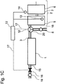
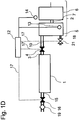
- FIG. 1A-1D schematically illustrate a humidity regulating device in accordance with preferred embodiments of the present invention.
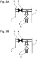
- FIGS 2A-2C schematically illustrate the switching mechanism of a humidity regulating device in accordance with embodiments of the present invention.
- FIG. 3 schematically illustrates the working principle of a humidity regulating device in accordance with embodiments of the present invention.
- Figure 1A and 1B schematically illustrate a device to regulate the relative humidity level in a CPV module.
- the module 2 consists of at least one module unit 5.
- Figure 1A schematically illustrates that module 2 comprises at least a module unit 5 and a module unit 6 which are connected in a gas conducting manner via duct 7.
- Figure 1B schematically illustrates that module 2 comprises at least a module unit 5 and a module unit 6 which are connected in a gas conducting manner via ducts 7'.
- the invention is not limited thereto and further module units could be included and connected in either the way displayed in Figure 1A and/or the way displayed in Figure 1B . This allows one to individually address module units (5, 6,...) or groups of module units via a central gas line tubing system.
- the device comprises a desiccant unit 1 connected to the module 2 via a first duct 3 on which is placed a first valve 4.
- the desiccant unit 1 can for instance contain absorber and/or adsorber material, in particular silica gel.
- the module 2 is also connected to ambient atmosphere via a second duct 8 on which is placed a second valve 9.
- the second duct 8 connects to the first duct 3 at an intersection 10.
- the first valve 4 on the first duct 3 is situated between the desiccant unit 1 and the intersection 10.
- a switching mechanism is actuated by a regulation unit 12 which allows gas flow between the module 2 and either the desiccant unit 1 or ambient atmosphere.
- the desiccant unit 1 is connected to ambient atmosphere via a third duct 15 on which is placed a third valve 16.
- the device includes at least one sensor 13 adapted to measure physical values with reference to the inside of the module 2 and/or at least one sensor 14 adapted to measure physical values with reference to the outside of the module 2 connected to the regulation unit 12.
- the regulation unit acts on a switching mechanism as indicated by dashed lines 17, thereby using the information inside the module from the sensor 13 and/or outside the module from the sensor 14.
- the switching mechanism comprises the first valve 4 and the second valve 9, or any other valve necessary in order to allow a gas flow between the module 2 and either the desiccant unit 1 or ambient atmosphere.
- a skilled person knows how to implement the connection 17 to the switching mechanism and the sensors, examples are either by simple wire connection or wireless communication.
- the openings to ambient atmosphere are equipped with particle filters 18 and 19.
- the regulation unit 12 and the switching mechanism assure that a connection allowing gas flow is established between the module 2 and either the desiccant unit 1 or ambient atmosphere.
- This is schematically illustrated in Figure 1A in that the first valve 4 on the first duct 3 and the third valve 16 on the third duct 15 are filled in black in order to show a closed position for instance of the valves and the second valve 9 on the second duct 8 is filled in white in order to show an open position of the valve, respectively.
- Gas flow is allowed between the module 2 and ambient atmosphere. This is in particular useful whenever the meteorological conditions indicate that there is no risk for condensation inside the module 2 by incoming air which is not passed by the desiccant unit 1 to dry the air on purpose.
- the regulation unit 12 uses the information inside the module 2 of sensors 13 and/or outside the module 2 of sensors 14 in order to decide whether to allow gas flow between the module 2 and ambient atmosphere or to allow gas flow between the module 2 and the desiccant unit 1. Comparing measures outside and inside the module permits a perfect evaluation of necessity to dry the incoming air.
- Figure 1A illustrates that whenever the first valve 4 on first duct 3 is actuated this is also the case in the same manner for the third valve 16 on duct 15 which connects the desiccant unit 1 to ambient atmosphere.
- a gas flow from ambient atmosphere to the module 2 occurs via the desiccant unit 1, for instance provoked by a depression inside the module 2, allowing dried air flow to the module 2 without any active transportation means like a fan.
- the third valve 16 on duct 15 could be a non-return valve, preventing gas flow from the desiccant unit 1 to ambient atmosphere.
- the non-return valve allows gas flow from ambient atmosphere to the desiccant unit 1 and, thus, dried air flow from the desiccant unit 1 to the module 2 via the first duct 3 and open first valve 4 whenever depression occurs in the module 2 and the regulation unit 12 opens the first valve 4 to the desiccant unit 1.
- the regulation unit 12 evaluates for instance the risk of condensation inside the module 2 by the measures of various parameters of the sensors 13 adapted to measure physical values with reference to the inside the module and/or the sensors 14 adapted to measure physical values with reference to the outside the module and controls the gas flow.
- Physical parameters as for instance pressure, temperature and relative humidity are most suitable, but one can also add further elements as for instance time and tracker position. Taking into account of these thermodynamic parameters for the regulation of the gas flow enables one to perfectly control and avoid the occurrence of condensation.
- the sensors 13, 14 do not have to be physically situated inside or outside the module, as for instance the case of an optically controlled measurement of the temperature through the transparent lens or bottom plate for CPV applications. Sensor 13 could be placed for instance in the central gas line tubing system, displaying a common information on physical values of all connected modules at once.
- FIGS 2A-2C schematically illustrate the switching mechanism of a humidity regulating device according to embodiments of the present invention and correspond to frame 11 of Figure 1A and 1B .
- FIG. 2A and Figure 2B schematically illustrate that the first valve 4 on the first duct 3 is filled in black, corresponding to a closed position of the valve, while the second valve 9 on the second duct 8 is filled in white, corresponding to an open position, respectively.
- the module unit 5 is connected to ambient atmosphere via second duct 8 and second valve 9.
- Figure 2A illustrates schematically the gas flow going from the module unit 5 to ambient atmosphere. This is possibly provoked by an overpressure inside the module unit 5.
- the gas is flowing from the module unit 5 to ambient atmosphere. Gas is expulsed from the module unit 5 and no ambient air flows to the module unit 5.
- FIG 2B schematically illustrates the gas flow going from ambient atmosphere to the module unit 5.
- Ambient air flows to the module unit 5 without passing through the desiccant unit 1. This is possibly provoked by a depression inside the module unit 5.
- the gas is flowing from ambient atmosphere to the module unit 5.
- this operating mode is particularly useful whenever the meteorological conditions indicate that there is no risk for condensation inside the module unit 5. It is thus possible to limit the use of the drying functionality of the desiccant unit 1 to certain conditions, in particular meteorological conditions with risk for condensation.
- Figure 2C schematically illustrates the gas flow going from the desiccant unit 1 to the module unit 5 via the first duct 3 and the first valve 4.
- Dried air from the desiccant unit 1 is provided to the module unit 5 in order to regulate the relative humidity level inside the module unit 5, in particular to avoid condensation inside the module unit 5.
- the flow is possibly provoked by a depression inside the module unit 5.
- the gas is flowing from the desiccant unit 1 to the module unit 5.
- both the first valve 4 on the first duct 3 and the second valve 9 on the second duct 8 can be replaced by a single valve of type L-valve 20, placed at the intersection 10 of the first duct 3 and the second duct 8, allowing in the shown case (the filled in black arrow indicates the closed position for the respective part to ambient atmosphere) the gas flow from the module unit 5 to the desiccant unit 1 via the first duct 3, controlled by the regulation unit 12.
- the use of the L-valve 20 not only allows a gas connection between the module unit 5 and the desiccant unit 1 as well as between the module unit 5 and ambient atmosphere, but also a gas connection can be established between the desiccant unit 1 and ambient atmosphere while the entrance to the module unit 5 is closed for gas flow. This would allow an easy access to connect a regeneration unit to the desiccant unit 1 which would reduce fixed installation costs and efforts for such a maintenance action.
- the module unit 5 is not connected to ambient atmosphere via the second duct 8 and second valve 9, but via an opening situated independently of the first duct 3 elsewhere on the module 2, with another valve 21 placed on this opening, as illustrated in Figure 1D as placed on the module unit 5.
- the invention is not limited to this. Whenever gas flow between the module 2 and ambient atmosphere is allowed, said valve on the opening of the module unit 5 is opened whereas the first valve 4 on the first duct 3 is closed, and vice versa. This gives the advantage that a breathing mode between the module unit 5 and ambient atmosphere can be maintained while maintenance is performed on the connected desiccant unit 1.
- At least one of the module units (5,6,...) can further comprise an non-return membrane which allows to evacuate an eventual overpressure inside the module to ambient atmosphere.
- This additional element has the further advantage that it is automatically switched or addressed and sustains the simple working principle of the humidity regulating device.
- Figure 3 schematically illustrates the working principle of a humidity regulating device according to embodiments of the present invention.
- the physical values used by the regulation unit 12 can be the pressure, the temperature inside the module unit 5 and outside the module unit 5, and the relative humidity inside the module unit 5.
- the invention is not limited neither to one sensor nor one particular module unit.
- Pmod indicates the pressure inside the module unit 5
- Pout indicates the pressure outside the module unit 5 corresponding to the ambient pressure.
- Tmod and rHmod indicate the temperature and the relative humidity inside the module, respectively.
- Tdp indicates the dew point temperature inside the module and can be determined from the values of Tmod and rHmod.
- the dew point temperature Tdp is the degree of temperature at which a part of the water vapor contained in a volume of air passes from gaseous to liquid form which corresponds to condensation. Tout indicates the temperature outside the module.
- FIG. 3 schematically illustrates, the three different operating modes of the switching mechanism as shown in the respective Figures 2A-2C are associated to different conditions based on the measures of the various parameters indicated above.
- Gas is flowing from ambient atmosphere to the module unit 5 via the second duct 8 and the open second valve 9.
- the temperature, Tout, outside the module unit 5 is approaching the dew point temperature, Tdp, inside the module unit 5 from higher temperatures by less than a predetermined threshold, preferentially 2°C
- the operating mode of Figure 2C applies.
- Gas is flowing from the desiccant unit 1 to the module unit 5 via the first duct 3 and the open first valve 4, providing dried gas from the desiccant unit 1 to the module unit 5.
- the next step consists in an evaluation of the initial condition of pressure difference inside and outside the module unit 5.
- each module unit comprised in the module 2 can have its own set of sensors.
- the measure taken into account by the regulation unit 12 can be for instance a local value inside a specific module unit or an average value of all measured values of a set of sensors inside a module unit, but it can also be the average value of the whole module 2.
- a third supplemental condition can be added, only taking into account the relative humidity level, rHout, outside the module.
- the operating mode of Figure 2B could be allowed only if the pressure, Pout, outside the module unit 5 is higher than the pressure, Pmod, inside the module unit 5, the temperature, Tout, outside the module unit 5 is exceeding the dew point temperature, Tdp, inside the module unit 5 by more than a predetermined temperature threshold, preferentially 2°C, and the relative humidity level, rHout, outside the module is below a predetermined humidity threshold, preferentially 70%.
- This supplemental condition allows a gas flow from ambient atmosphere to the module unit 5 not only based on the dew point temperature, Tdp, inside the module unit 5, only allowing relatively dry air from the outside and, thus, avoiding entering excessively humid air from ambient atmosphere to the module unit 5.
- This provides the advantage to decouple the parameter of relative humidity from the mixed parameter of dew point temperature, allowing more flexibility.
- the operating mode of Figure 2C would be allowed if the pressure, Pout, outside the module unit 5 is higher than the pressure, Pmod, inside the module unit 5, the temperature, Tout, outside the module unit 5 is exceeding the dew point temperature, Tdp, inside the module unit 5 by more than a predetermined temperature threshold, preferentially 2°C, and the relative humidity level, rHout, outside the module exceeds a predetermined humidity threshold, preferentially 70%. Even if practically no condensation would occur in the module unit 5, excessively humid air would be avoided entering the module unit 5.
- the working principle of the humidity regulating device is based on the comparison of the physical values of only one sensor, in a configuration similar to for instance Figure 1A to 1D omitting either the sensor 13 adapted to measure physical values with reference to the inside of the module or the sensor 14 adapted to measure physical values with reference to the outside of the module, to a predetermined threshold, in particular for the operating mode illustrated schematically in Figure 2B and 2C .
- the operating mode 2C applies for the case that the temperature inside or outside the module, depending on which sensor 13, 14 is kept in place, is higher than the predetermined temperature threshold.
- the operating mode 2C applies for the case that the relative humidity inside or outside the module, depending on which sensor 13, 14 is installed, is lower than the predetermined relative humidity threshold.
- operating mode 2C applies for a combined measure of temperature and relative humidity, with the temperature inside or outside the module lower than the predetermined temperature threshold and the relative humidity inside or outside the module higher than the predetermined relative humidity threshold.
- the dew point temperature is derived from such combined measures of temperature and relative humidity, and for temperatures below this dew point temperature condensation can occur.
- a possible way to identify the temperature and relative humidity thresholds relies therefore on the ensemble of combined data points of temperature and relative humidity, for example throughout the year, which results in a mapping of the dew point temperature.
- the gas flow between the desiccant unit 1 and the module 2 could therefore be allowed if the outside or inside temperature of the module is lower than such a derived and, thus, predetermined threshold.
- a same reasoning can be applied taking into account the relative humidity values only, deriving a threshold value for the relative humidity based on the mapping of dew point temperatures taking into account the minimal temperature for each point, leading to a mapping of maximum relative humidity values.
- Thresholds based on the combined measures of temperature and relative humidity can be more precisely adjusted and, thus, the thresholds evaluated in a more narrow range, than thresholds based on temperature and relative humidity only.
- the latter can be of particular interest for instance in cases in which the annual variation of one of both values fo temperature and relative humidity is negligible as for instance for countries close to the equator.
- the temperature and relative humidity data can also include the annual or seasonal but also even daily variations of the measured parameters. The humidity regulating device thus could even adapt and change threshold values throughout the year in order to optimize the efficiency of the system because the critical conditions might differ for example with the different seasons.
- the device of the present invention can comprise several desiccant units.
Landscapes
- Engineering & Computer Science (AREA)
- Chemical & Material Sciences (AREA)
- Life Sciences & Earth Sciences (AREA)
- Sustainable Development (AREA)
- Sustainable Energy (AREA)
- Thermal Sciences (AREA)
- Physics & Mathematics (AREA)
- Combustion & Propulsion (AREA)
- Mechanical Engineering (AREA)
- General Engineering & Computer Science (AREA)
- Drying Of Gases (AREA)
- Manufacturing & Machinery (AREA)
- Drying Of Solid Materials (AREA)
Description
- The present invention generally relates to a device and a method for regulating the relative humidity level inside a solar cell module. The device and the method are particularly well suited for concentrator photovoltaic (CPV) modules.
- In CPV modules, the incident light, in particular the solar radiation, is concentrated on a photovoltaic cell by an optical system comprising, e.g., a mirror or a lens, such as a Fresnel lens or a spherical lens. The cell is thereby positioned at the focus of the lens. Commonly, such CPV modules are mounted, alone or combined in arrays, on tracking units in order to be optimally oriented towards the incident light, in particular following the brightest region in the sky. Preferably, CPV modules should be sealed completely to avoid degrading of the solar cells and other electrical components, e.g. the bypass diodes or the electrical wiring, due to environmental influences. In particular, an elevated level of relative humidity in the module which can cause under certain circumstances condensation of water vapor on the components situated inside the module.
- Several prior art approaches for resolving the problem of condensation and humidity inside a solar module are known, as shown, for example, in
EP0546481 A1 . A first approach is based on a completely sealed solar module. Prior art documentWO2011085086A2 discloses an entirely sealed solar module in which the solar module is connected to an expansion bag accommodating for the pressure changes inside a solar module during thermal cycling. Optionally a supplemental
desiccant unit is installed to remove moisture that has penetrated into the sealed module. This approach is not well adapted to large CPV module and plants, due to the huge dimensioning of the expansion bag. - In another approach, disclosed in prior art document
WO2009146842A1 , an adsorber or desiccant unit is connected to the module which role is to dry the incoming air. Adsorption is a phenomenon leading to the physico-chemical fixation of molecules of water vapor on the surface of a solid, in particular an adsorber or desiccant material, as for instance a silica gel which is characterized by a high porosity. Moist air from outside the module is blown with a fan through the adsorber unit, in particular containing as adsorber material a silica gel, which absorbs excess moisture, and dried air is sent directly to the CPV modules. However, with time, the adsorbent becomes saturated and must be regenerated to remove moisture. This regeneration generally takes place when the relative humidity measured after the adsorbent unit is above a certain limit, and the regeneration duration depends on this relative humidity level. This regeneration is ensured by the passage of air heated to a temperature above 60 °C and the moist hot air has to be evacuated outside. - This regeneration phase is highly energy consuming and needs an active device assuring the flow of air, in particular a fan. Moreover, lack of supervisory control and communication leads to an unnecessary use of the drying unit, even when the outside meteorological conditions are optimal to avoid to dry modules, in particular elevated outside temperature and low relative humidity outside the module.
- The objective of the invention is to propose a device and a process for regulating the relative humidity level inside a solar cell module obviating the above-mentioned detriments.
- The present invention relates to a device according to
claim 1 to regulate the relative humidity level in a CPV module. - This regulation enables one to limit the use of the desiccant unit and, thus, reduce energy consumption due to the regeneration phase and also, by decreasing the use of the desiccant unit, one prevents precipitate saturation of the latter. By adjusting the capacity of the desiccant unit, it is possible to create a self-correcting and maintenance free humidity regulation unit for a CPV system containing at least one module.
- In further advantageous embodiments, the regulation unit of the humidity regulating device comprises at least a sensor adapted to measure physical values with reference to the inside of the module or at least a sensor adapted to measure physical values with reference to the outside of the module, and in which the regulation unit records and compares the measures with predetermined thresholds to actuate the switching mechanism.
- In further advantageous embodiments, the regulation unit of the humidity regulating device comprises at least a sensor adapted to measure physical values with reference to the inside of the module and at least a sensor adapted to measure physical values with reference to the outside of the module, and in which the regulation unit records and compares their measures to actuate the switching mechanism. The physical values measured can respectively be the temperature, relative humidity, and pressure, inside and outside the module.
- These two embodiments provide the beneficial effect that an intelligent regulation of the humidity regulating device is made possible, in particular by taking into account any possible environmental factor, in particular thermodynamic parameters directly related to condensation, relevant for the good functionality of a CPV system.
- In further advantageous embodiments, the module of the humidity regulating device is connected to ambient atmosphere via a second duct connected to said first duct at an intersection, the switching mechanism comprising a first valve placed on the first duct between the desiccant unit and the intersection, and comprising a second valve placed on the second duct between the intersection and the ambient atmosphere.
- In an alternative embodiment, the module of the humidity regulating device is connected to ambient atmosphere via a second duct connected to said first duct at an intersection, the switching mechanism comprising a L-valve placed at the intersection.
- These two embodiments provide the beneficial advantage that the same connection of the desiccant unit to the module can be used for both types of gas flow, the one between the desiccant unit and the module and the one between ambient atmosphere and the module. Thus only one entrance or opening is needed on the side of the module.
- In an alternative embodiment, the module of the humidity regulating device is connected to ambient atmosphere via an opening placed on the module, the switching mechanism comprising valves placed on the first duct and the opening.
- In further advantageous embodiments, the humidity regulating device further comprises a non-return membrane place on at least one of the module units able to evacuate overpressure from inside the module to ambient atmosphere.
- This provides the beneficial advantage that a gas flow could be allowed between the module and ambient atmosphere while the desiccant unit could be disconnected for maintenance reasons. Maintenance efforts are therefore reduced as no stop of the system is required.
- In further advantageous embodiments, the humidity regulating device allows the gas flow between the module and the desiccant unit when the regulation unit records a pressure in the module inferior to the pressure outside the module and the temperature inside or outside the module is lower than the predetermined temperature threshold and/or the relative humidity inside or outside the module is higher than the predetermined relative humidity threshold.
- In further advantageous embodiments, the humidity regulating device allows the gas flow between the module and ambient atmosphere when the regulation unit records a pressure in the module inferior to the pressure outside the module and the temperature inside or outside the module is higher than the predetermined temperature threshold and/or the relative humidity inside or outside the module is lower than the predetermined relative humidity threshold.
- These two embodiments provide the beneficial advantage that with only one sensor present to measure physical values inside or outside the module an efficient savings on the desiccant unit can be obtained.
- In further advantageous embodiments, the humidity regulating device allows the gas flow between the module and the desiccant unit when the regulation unit records a pressure in the module inferior to the pressure outside the module and a temperature outside the module which is approaching the dew point temperature inside the module, the dew point being calculated from the measure of the temperature and relative humidity inside the module, from higher temperatures by less than a predetermined threshold, preferentially 2°C.
- This provides the beneficial advantage that no active device is needed to support a gas flow, but the depression inside the module triggers the gas flow of dried air from the desiccant unit to the module when the temperature outside the module is colder than the dew point temperature plus a predetermined threshold, in particular 2°C.
- In further advantageous embodiments, the humidity regulating device allows the gas flow between the module and the ambient atmosphere when the regulation unit records a pressure in the module inferior to the pressure outside the module and the outside temperature is exceeding the dew point temperature inside the module, the dew point being calculated from the measure of the temperature and relative humidity inside the module, by more than a predetermined threshold, preferentially 2°C.
- This provides the beneficial advantage that the desiccant unit is not used and gas flow to the module, induced by the depression in the module, is allowed when the meteorological conditions are favorable, in particular the temperature outside the module is higher than the dew point temperature plus a predetermined threshold, in particular 2°C. A use to a lesser extent of the desiccant unit reduces the need of regeneration. Or by keeping a certain frequency of regeneration, much less desiccant material can be used and, thus, one can benefit of longer maintenance free periods.
- In further advantageous embodiments, the humidity regulating device allows the gas flow between the module and the ambient atmosphere when the regulation unit records a pressure in the module superior to the pressure outside the module.
- This provides the beneficial advantage that overpressure in the module is evacuated from the system without need of any active flow or pump device.
- In further advantageous embodiments, the humidity regulating device allows the gas flow between the module and the desiccant unit when the regulation unit records a pressure in the module inferior to the pressure outside the module and the outside temperature is exceeding the dew point temperature inside the module, the dew point being calculated from the measure of the temperature and relative humidity inside the module, by more than a predetermined threshold, preferentially 2°C, and the relative humidity level outside the module exceeds a predetermined threshold, preferentially 70%.
- In further advantageous embodiments, the humidity regulating device allows the gas flow between the module and the ambient atmosphere when the regulation unit records a pressure in the module inferior to the pressure outside the module and the outside temperature is exceeding the dew point temperature inside the module, the dew point being calculated from the measure of the temperature and relative humidity inside the module, by less than a predetermined threshold, preferentially 2°C, and the relative humidity level outside the module is inferior to a predetermined threshold, preferentially 70%.
- These two embodiments provide the beneficial advantage that not only the dew point temperature can be taken into account to regulate the gas flow, but one decouples the second parameter relative humidity from the mixed parameter dew point temperature.
- In further advantageous embodiments, the desiccant unit of the humidity regulating device comprises an opening to ambient atmosphere, the opening comprising a third valve, which is opened only when the gas flow is allowed between the module and the desiccant unit.
- In an alternative embodiment, the desiccant unit of the humidity regulating device comprises an opening to ambient atmosphere, the opening comprising a non-return valve.
- These two embodiments provide the beneficial advantage that for the desiccant unit that a breathing mode is possible between the module and ambient atmosphere, with the desiccant unit switched in between whenever the meteorological conditions require humidity regulation inside the module.
- In further advantageous embodiments, a particle filter is placed on at least one of the connections to ambient atmosphere.
- This provides the beneficial advantage that the functionality of the system is increased, in particular by avoiding particles sensitive to the relative humidity could damage the electrical components of the module.
- In further advantageous embodiments, the desiccant unit of the humidity regulating contains absorber and/or adsorber materials, in particular silica gel.
- This latter provides the beneficial advantage that the high porosity material of the silica gel optimizes the adsorption performance of the desiccant unit and, thus, less amount of material is needed with respect to other generally used materials.
- In further advantageous embodiments, the at least one module unit of the module are connected in a gas conducting manner via a duct.
- This provides the beneficial advantage that either the module units can be connected with each other and, thus, in a grouped manner to the desiccant unit and/or individually, via for instance a central tubing system which addresses each module unit individually, in order to be regulated by the switching mechanism.
- Further, the present invention can also relate to a humidity regulating process using the humidity regulating device, in particular adapted for modules used for CPV.
- The invention will be described in more detail by way of example hereinafter using advantageous embodiments and with reference to the drawings. The described embodiments are only possible configurations in which the individual features may however, as described above, be implemented independently of each other or may be omitted. Equal elements illustrated in the drawings are provided with equal reference signs. Parts of the description relating to equal elements illustrated in the different drawings may be left out.
-
Figure 1A-1D schematically illustrate a humidity regulating device in accordance with preferred embodiments of the present invention. -
Figures 2A-2C schematically illustrate the switching mechanism of a humidity regulating device in accordance with embodiments of the present invention. -
Figure 3 schematically illustrates the working principle of a humidity regulating device in accordance with embodiments of the present invention. - The present invention will now be described with reference to specific embodiments. It will be apparent to the skilled person that features and alternatives from any of the embodiments can be combined, independently of each other, with features and alternatives of any other embodiment in accordance with the scope of the claims.
- In particular,
Figure 1A and1B schematically illustrate a device to regulate the relative humidity level in a CPV module. Themodule 2 consists of at least onemodule unit 5.Figure 1A schematically illustrates thatmodule 2 comprises at least amodule unit 5 and amodule unit 6 which are connected in a gas conducting manner viaduct 7.Figure 1B schematically illustrates thatmodule 2 comprises at least amodule unit 5 and amodule unit 6 which are connected in a gas conducting manner via ducts 7'. However, the invention is not limited thereto and further module units could be included and connected in either the way displayed inFigure 1A and/or the way displayed inFigure 1B . This allows one to individually address module units (5, 6,...) or groups of module units via a central gas line tubing system. - The device comprises a
desiccant unit 1 connected to themodule 2 via afirst duct 3 on which is placed afirst valve 4. Thedesiccant unit 1 can for instance contain absorber and/or adsorber material, in particular silica gel. - The
module 2 is also connected to ambient atmosphere via asecond duct 8 on which is placed asecond valve 9. Thesecond duct 8 connects to thefirst duct 3 at anintersection 10. Thefirst valve 4 on thefirst duct 3 is situated between thedesiccant unit 1 and theintersection 10. A switching mechanism is actuated by aregulation unit 12 which allows gas flow between themodule 2 and either thedesiccant unit 1 or ambient atmosphere. In a non-limitative way, thedesiccant unit 1 is connected to ambient atmosphere via athird duct 15 on which is placed athird valve 16. - The device according to the invention includes at least one
sensor 13 adapted to measure physical values with reference to the inside of themodule 2 and/or at least onesensor 14 adapted to measure physical values with reference to the outside of themodule 2 connected to theregulation unit 12. As schematically illustrated, the regulation unit acts on a switching mechanism as indicated by dashedlines 17, thereby using the information inside the module from thesensor 13 and/or outside the module from thesensor 14. The switching mechanism comprises thefirst valve 4 and thesecond valve 9, or any other valve necessary in order to allow a gas flow between themodule 2 and either thedesiccant unit 1 or ambient atmosphere. A skilled person knows how to implement theconnection 17 to the switching mechanism and the sensors, examples are either by simple wire connection or wireless communication. - The openings to ambient atmosphere are equipped with
particle filters - The
regulation unit 12 and the switching mechanism assure that a connection allowing gas flow is established between themodule 2 and either thedesiccant unit 1 or ambient atmosphere. This is schematically illustrated inFigure 1A in that thefirst valve 4 on thefirst duct 3 and thethird valve 16 on thethird duct 15 are filled in black in order to show a closed position for instance of the valves and thesecond valve 9 on thesecond duct 8 is filled in white in order to show an open position of the valve, respectively. Gas flow is allowed between themodule 2 and ambient atmosphere. This is in particular useful whenever the meteorological conditions indicate that there is no risk for condensation inside themodule 2 by incoming air which is not passed by thedesiccant unit 1 to dry the air on purpose. Theregulation unit 12 uses the information inside themodule 2 ofsensors 13 and/or outside themodule 2 ofsensors 14 in order to decide whether to allow gas flow between themodule 2 and ambient atmosphere or to allow gas flow between themodule 2 and thedesiccant unit 1. Comparing measures outside and inside the module permits a perfect evaluation of necessity to dry the incoming air. -
Figure 1A illustrates that whenever thefirst valve 4 onfirst duct 3 is actuated this is also the case in the same manner for thethird valve 16 onduct 15 which connects thedesiccant unit 1 to ambient atmosphere. A gas flow from ambient atmosphere to themodule 2 occurs via thedesiccant unit 1, for instance provoked by a depression inside themodule 2, allowing dried air flow to themodule 2 without any active transportation means like a fan. - In an alternative, the
third valve 16 onduct 15 could be a non-return valve, preventing gas flow from thedesiccant unit 1 to ambient atmosphere. The non-return valve allows gas flow from ambient atmosphere to thedesiccant unit 1 and, thus, dried air flow from thedesiccant unit 1 to themodule 2 via thefirst duct 3 and openfirst valve 4 whenever depression occurs in themodule 2 and theregulation unit 12 opens thefirst valve 4 to thedesiccant unit 1. - The
regulation unit 12 evaluates for instance the risk of condensation inside themodule 2 by the measures of various parameters of thesensors 13 adapted to measure physical values with reference to the inside the module and/or thesensors 14 adapted to measure physical values with reference to the outside the module and controls the gas flow. Physical parameters as for instance pressure, temperature and relative humidity are most suitable, but one can also add further elements as for instance time and tracker position. Taking into account of these thermodynamic parameters for the regulation of the gas flow enables one to perfectly control and avoid the occurrence of condensation. Further, thesensors Sensor 13 could be placed for instance in the central gas line tubing system, displaying a common information on physical values of all connected modules at once. -
Figures 2A-2C schematically illustrate the switching mechanism of a humidity regulating device according to embodiments of the present invention and correspond to frame 11 ofFigure 1A and1B . -
Figure 2A and Figure 2B schematically illustrate that thefirst valve 4 on thefirst duct 3 is filled in black, corresponding to a closed position of the valve, while thesecond valve 9 on thesecond duct 8 is filled in white, corresponding to an open position, respectively. In both cases themodule unit 5 is connected to ambient atmosphere viasecond duct 8 andsecond valve 9. -
Figure 2A illustrates schematically the gas flow going from themodule unit 5 to ambient atmosphere. This is possibly provoked by an overpressure inside themodule unit 5. In order to equilibrate the difference in pressure inside themodule unit 5 with respect to the pressure outside themodule unit 5, the gas is flowing from themodule unit 5 to ambient atmosphere. Gas is expulsed from themodule unit 5 and no ambient air flows to themodule unit 5. -
Figure 2B schematically illustrates the gas flow going from ambient atmosphere to themodule unit 5. Ambient air flows to themodule unit 5 without passing through thedesiccant unit 1. This is possibly provoked by a depression inside themodule unit 5. In order to equilibrate the difference in pressure inside themodule unit 5 with respect to the pressure outside themodule unit 5, the gas is flowing from ambient atmosphere to themodule unit 5. As already mentioned this operating mode is particularly useful whenever the meteorological conditions indicate that there is no risk for condensation inside themodule unit 5. It is thus possible to limit the use of the drying functionality of thedesiccant unit 1 to certain conditions, in particular meteorological conditions with risk for condensation. -
Figure 2C schematically illustrates the gas flow going from thedesiccant unit 1 to themodule unit 5 via thefirst duct 3 and thefirst valve 4. Dried air from thedesiccant unit 1 is provided to themodule unit 5 in order to regulate the relative humidity level inside themodule unit 5, in particular to avoid condensation inside themodule unit 5. The flow is possibly provoked by a depression inside themodule unit 5. In order to equilibrate the difference in pressure inside themodule unit 5 with respect to the pressure outside themodule unit 5, the gas is flowing from thedesiccant unit 1 to themodule unit 5. - In an alternative, shown in
Figure 1C , both thefirst valve 4 on thefirst duct 3 and thesecond valve 9 on thesecond duct 8 can be replaced by a single valve of type L-valve 20, placed at theintersection 10 of thefirst duct 3 and thesecond duct 8, allowing in the shown case (the filled in black arrow indicates the closed position for the respective part to ambient atmosphere) the gas flow from themodule unit 5 to thedesiccant unit 1 via thefirst duct 3, controlled by theregulation unit 12. The use of the L-valve 20 not only allows a gas connection between themodule unit 5 and thedesiccant unit 1 as well as between themodule unit 5 and ambient atmosphere, but also a gas connection can be established between thedesiccant unit 1 and ambient atmosphere while the entrance to themodule unit 5 is closed for gas flow. This would allow an easy access to connect a regeneration unit to thedesiccant unit 1 which would reduce fixed installation costs and efforts for such a maintenance action. - In an alternative the
module unit 5 is not connected to ambient atmosphere via thesecond duct 8 andsecond valve 9, but via an opening situated independently of thefirst duct 3 elsewhere on themodule 2, with anothervalve 21 placed on this opening, as illustrated inFigure 1D as placed on themodule unit 5. However, the invention is not limited to this. Whenever gas flow between themodule 2 and ambient atmosphere is allowed, said valve on the opening of themodule unit 5 is opened whereas thefirst valve 4 on thefirst duct 3 is closed, and vice versa. This gives the advantage that a breathing mode between themodule unit 5 and ambient atmosphere can be maintained while maintenance is performed on the connecteddesiccant unit 1. - In an alternative at least one of the module units (5,6,...) can further comprise an non-return membrane which allows to evacuate an eventual overpressure inside the module to ambient atmosphere. This additional element has the further advantage that it is automatically switched or addressed and sustains the simple working principle of the humidity regulating device.
-
Figure 3 schematically illustrates the working principle of a humidity regulating device according to embodiments of the present invention. With reference toFigure 1A to 1D schematically representing onesensor 13 adapted to measure physical values inside themodule unit 5 and onesensor 14 adapted to measure physical values outside themodule 2, the physical values used by theregulation unit 12 can be the pressure, the temperature inside themodule unit 5 and outside themodule unit 5, and the relative humidity inside themodule unit 5. However, the invention is not limited neither to one sensor nor one particular module unit. Pmod indicates the pressure inside themodule unit 5, Pout indicates the pressure outside themodule unit 5 corresponding to the ambient pressure. Tmod and rHmod indicate the temperature and the relative humidity inside the module, respectively. Tdp indicates the dew point temperature inside the module and can be determined from the values of Tmod and rHmod. The dew point temperature Tdp is the degree of temperature at which a part of the water vapor contained in a volume of air passes from gaseous to liquid form which corresponds to condensation. Tout indicates the temperature outside the module. - As
Figure 3 schematically illustrates, the three different operating modes of the switching mechanism as shown in the respectiveFigures 2A-2C are associated to different conditions based on the measures of the various parameters indicated above. - In particular, when the pressure inside the
module unit 5 Pmod is higher than the pressure outside themodule unit 5 Pout, the operating mode ofFigure 2A applies. Gas is flowing from themodule unit 5 to ambient atmosphere via thesecond duct 8 and the opensecond valve 9, but this may also take place via the above described additional module non-return membrane which allows over-pressure evacuation. The next step consists in an evaluation of the initial condition of pressure difference inside and outside themodule unit 5. - In case that the pressure, Pout, outside the
module unit 5 is higher than the pressure, Pmod, inside themodule unit 5, a second condition depending on the comparison of the temperature, Tout, outside themodule unit 5 and the dew point temperature, Tdp, inside themodule unit 5 is implemented. As mentioned before, at temperatures below the dew point temperature condensation generally occurs. In order to avoid the critical point of the dew point temperature Tdp and condensation inside the module, a predetermined threshold of x°C as indicated inFigure 3 , preferentially 2°C, is implemented in the second condition. When the temperature, Tout, outside themodule unit 5 is exceeding the dew point temperature, Tdp, inside themodule unit 5 by more than the predetermined threshold, preferentially 2°C, the operating mode ofFigure 2B applies. Gas is flowing from ambient atmosphere to themodule unit 5 via thesecond duct 8 and the opensecond valve 9. However, when the temperature, Tout, outside themodule unit 5 is approaching the dew point temperature, Tdp, inside themodule unit 5 from higher temperatures by less than a predetermined threshold, preferentially 2°C, the operating mode ofFigure 2C applies. Gas is flowing from thedesiccant unit 1 to themodule unit 5 via thefirst duct 3 and the openfirst valve 4, providing dried gas from thedesiccant unit 1 to themodule unit 5. In both cases depending on the second condition, the next step consists in an evaluation of the initial condition of pressure difference inside and outside themodule unit 5. - The different operating modes of the switching mechanism depend on the measure of the sensors described before. In a non-limitative way, each module unit comprised in the
module 2, can have its own set of sensors. The measure taken into account by theregulation unit 12 can be for instance a local value inside a specific module unit or an average value of all measured values of a set of sensors inside a module unit, but it can also be the average value of thewhole module 2. - In an alternative, a third supplemental condition can be added, only taking into account the relative humidity level, rHout, outside the module. In particular, the operating mode of
Figure 2B could be allowed only if the pressure, Pout, outside themodule unit 5 is higher than the pressure, Pmod, inside themodule unit 5, the temperature, Tout, outside themodule unit 5 is exceeding the dew point temperature, Tdp, inside themodule unit 5 by more than a predetermined temperature threshold, preferentially 2°C, and the relative humidity level, rHout, outside the module is below a predetermined humidity threshold, preferentially 70%. This supplemental condition allows a gas flow from ambient atmosphere to themodule unit 5 not only based on the dew point temperature, Tdp, inside themodule unit 5, only allowing relatively dry air from the outside and, thus, avoiding entering excessively humid air from ambient atmosphere to themodule unit 5. This provides the advantage to decouple the parameter of relative humidity from the mixed parameter of dew point temperature, allowing more flexibility. The operating mode ofFigure 2C would be allowed if the pressure, Pout, outside themodule unit 5 is higher than the pressure, Pmod, inside themodule unit 5, the temperature, Tout, outside themodule unit 5 is exceeding the dew point temperature, Tdp, inside themodule unit 5 by more than a predetermined temperature threshold, preferentially 2°C, and the relative humidity level, rHout, outside the module exceeds a predetermined humidity threshold, preferentially 70%. Even if practically no condensation would occur in themodule unit 5, excessively humid air would be avoided entering themodule unit 5. - In alternative embodiments, the working principle of the humidity regulating device is based on the comparison of the physical values of only one sensor, in a configuration similar to for instance
Figure 1A to 1D omitting either thesensor 13 adapted to measure physical values with reference to the inside of the module or thesensor 14 adapted to measure physical values with reference to the outside of the module, to a predetermined threshold, in particular for the operating mode illustrated schematically inFigure 2B and2C . In one alternative, the operating mode 2C applies for the case that the temperature inside or outside the module, depending on whichsensor sensor desiccant unit 1 and themodule 2 could therefore be allowed if the outside or inside temperature of the module is lower than such a derived and, thus, predetermined threshold. A same reasoning can be applied taking into account the relative humidity values only, deriving a threshold value for the relative humidity based on the mapping of dew point temperatures taking into account the minimal temperature for each point, leading to a mapping of maximum relative humidity values. Thresholds based on the combined measures of temperature and relative humidity can be more precisely adjusted and, thus, the thresholds evaluated in a more narrow range, than thresholds based on temperature and relative humidity only. However the latter can be of particular interest for instance in cases in which the annual variation of one of both values fo temperature and relative humidity is negligible as for instance for countries close to the equator. Further the temperature and relative humidity data can also include the annual or seasonal but also even daily variations of the measured parameters. The humidity regulating device thus could even adapt and change threshold values throughout the year in order to optimize the efficiency of the system because the critical conditions might differ for example with the different seasons. - All previously discussed embodiments are not intended as limitations but serve as examples illustrating features and advantages of the invention. It has to be understood that some or all of the above described features can also be combined in different ways.
- Although as illustrated in
Figures 1A to 1D the device of the present invention can comprise several desiccant units.
Claims (15)
- Device to regulate the relative humidity level in a CPV module (2) which can comprise at least one module unit (5,6,...), the device comprising a desiccant unit (1) connectable to the module (2) via a duct (3), and to ambient atmosphere, the device being characterised in that the device comprises a switching mechanism (4, 9) which is actuated by a regulation unit (12) based on thermodynamic parameters directly related to condensation, allowing a gas flow to the module (2) from either the desiccant unit (1) or ambient atmosphere.
- Humidity regulating device according to claim 1, in which the regulation unit (12) comprises at least a sensor (13) adapted for measuring physical values with reference to the inside of the CPV module (2) or at least a sensor (14) adapted for measuring physical values with reference to the outside of the CPV module (2) and in which the regulation unit (12) records and compares the measures with predetermined thresholds to actuate the switching mechanism (4, 9).
- Humidity regulating device according to claim 1, in which the regulation unit (12) comprises at least a sensor (13) adapted for measuring physical values with reference to the inside of the CPV module (2) and at least a sensor (14) adapted for measuring physical values with reference to the outside of the CPV module (2), and in which the regulation unit (12) records and compares their measures to actuate the switching mechanism (4, 9).
- Humidity regulating device according to one of the preceding claims 2 and 3, in which the physical values can respectively be the temperature, relative humidity, and pressure, inside and/or outside the CPV module (2).
- Humidity regulating device according to one of the preceding claims, in which the module (2) is connected to ambient atmosphere via a second duct (8) connected to said first duct at an intersection (10), the switching mechanism (4, 9) comprising a first valve (4) placed on the first duct (3) between the desiccant unit (1) and the intersection (10), and comprising a second valve (9) placed on the second duct (8) between the intersection (10) and the ambient atmosphere.
- Humidity regulating device according to one of the preceding claims 1 to 4, in which the module (2) is connected to ambient atmosphere via a second duct (8) connected to the first duct (3) at an intersection (10), the switching mechanism comprising a L-valve (20) placed at the intersection (10).
- Humidity regulating device according to one of the preceding claims 1 to 4, in which the module (2) is connected to ambient atmosphere via an opening placed on the module, the switching mechanism comprising valves (4, 21) placed on the first duct (3) and the opening.
- Humidity regulating device according to one of the preceding claims 5 to 7 further comprising a non-return membrane placed on at least one module unit (5,6,...) able to evacuate overpressure from the inside of the module (2) to ambient atmosphere.
- Humidity regulating device according to one of the preceding claims 2 and 4 to 8 in which the gas flow between the module (2) and the desiccant unit (1) is allowed when the regulation unit (12) records a pressure in the module (2) inferior to the pressure outside the module (2) and the temperature inside or outside the module (2) is lower than the predetermined temperature threshold and/or the relative humidity inside or outside the module (2) is higher than the predetermined relative humidity threshold.
- Humidity regulating device according to one of the preceding claims 2 and 4 to 8 in which the gas flow between the module (2) and ambient atmosphere is allowed when the regulation unit (12) records a pressure in the module (2) inferior to the pressure outside the module (2) and the temperature inside or outside the module (2) is higher than the predetermined temperature threshold and/or the relative humidity inside or outside the module (2) is lower than the predetermined relative humidity threshold.
- Humidity regulating device according to one of the preceding claims 3 to 8, in which the gas flow between the module (2) and the desiccant unit (1) is allowed when the regulation unit (12) records a pressure in the module (2) inferior to the pressure outside the module (2) and a temperature outside the module (2) which is approaching the dew point temperature inside the module (2), the dew point being calculated from the measure of the temperature and relative humidity inside the module (2), from higher temperatures by less than a predetermined threshold, preferentially 2°C.
- Humidity regulating device according to one of the preceding claims 3 to 8, in which the gas flow between the module (2) and the ambient atmosphere is allowed when the regulation unit (12) records a pressure in the module (2) inferior to the pressure outside the module (2) and the outside temperature is exceeding the dew point temperature inside the module (2), the dew point being calculated from the measure of the temperature and relative humidity inside the module (2), by more than a predetermined threshold, preferentially 2°C.
- Humidity regulating device according to one of the preceding claims 3 to 8, in which the gas flow between the module (2) and the desiccant unit (1) is allowed when the regulation unit (12) records a pressure in the module (2) inferior to the pressure outside the module (2) and the outside temperature is exceeding the dew point temperature inside the module (2), the dew point being calculated from the measure of the temperature and relative humidity inside the module (2), by more than a predetermined threshold, preferentially 2°C, and the relative humidity level outside the module (2) exceeds a predetermined threshold, preferentially 70%.
- Humidity regulating device according to one of the preceding claims 3 to 8, in which the gas flow between the module (2) and the ambient atmosphere is allowed when the regulation unit (12) records a pressure in the module (2) inferior to the pressure outside the module (2) and the outside temperature is exceeding the dew point temperature inside the module (2), the dew point being calculated from the measure of the temperature and relative humidity inside the module (2), by less than a predetermined threshold, preferentially 2°C. and the relative humidity level outside the module (2) is inferior to a predetermined threshold, preferentially 70%.
- Humidity regulation process using the humidity regulating device according to one of the preceding claims 1 to 14.
Applications Claiming Priority (2)
| Application Number | Priority Date | Filing Date | Title |
|---|---|---|---|
| FR1351665A FR3002659B1 (en) | 2013-02-26 | 2013-02-26 | DEVICE FOR CONTROLLING THE RELATIVE HUMIDITY LEVEL IN A CONCENTRATED PHOTOVOLTAIC MODULE |
| PCT/EP2014/000389 WO2014131492A1 (en) | 2013-02-26 | 2014-02-12 | Device to regulate the relative humidity level in a cpv module |
Publications (2)
| Publication Number | Publication Date |
|---|---|
| EP2962048A1 EP2962048A1 (en) | 2016-01-06 |
| EP2962048B1 true EP2962048B1 (en) | 2019-01-02 |
Family
ID=48652252
Family Applications (1)
| Application Number | Title | Priority Date | Filing Date |
|---|---|---|---|
| EP14705032.2A Not-in-force EP2962048B1 (en) | 2013-02-26 | 2014-02-12 | Device to regulate the relative humidity level in a cpv module |
Country Status (7)
| Country | Link |
|---|---|
| US (1) | US10746439B2 (en) |
| EP (1) | EP2962048B1 (en) |
| CN (1) | CN105074348B (en) |
| CA (1) | CA2940863C (en) |
| ES (1) | ES2716608T3 (en) |
| FR (1) | FR3002659B1 (en) |
| WO (1) | WO2014131492A1 (en) |
Families Citing this family (2)
| Publication number | Priority date | Publication date | Assignee | Title |
|---|---|---|---|---|
| CN108826527B (en) * | 2018-07-09 | 2020-12-04 | 徐州创之社通用技术产业研究院有限公司 | Solar energy component with simple humidity level adjusting function |
| CN115332651B (en) * | 2022-08-19 | 2025-05-06 | 东风柳州汽车有限公司 | Control method, device, equipment and storage medium for preventing power battery pack from being damaged |
Family Cites Families (15)
| Publication number | Priority date | Publication date | Assignee | Title |
|---|---|---|---|---|
| DE4141195C2 (en) * | 1991-12-13 | 1993-12-09 | Friedrich Mueller | Solar collector |
| TW336271B (en) | 1995-06-13 | 1998-07-11 | Sanyo Electric Co | Solar generator and an air conditioner with such a solar generator |
| KR100257902B1 (en) * | 1998-03-27 | 2000-06-01 | 윤종용 | System and method for environmental analysis in cleanroom |
| US6220039B1 (en) * | 1998-06-15 | 2001-04-24 | Honeywell International Inc. | Method of humidity control utilizing dewpoint |
| US7014932B2 (en) * | 2003-03-19 | 2006-03-21 | Proton Energy Systems, Inc. | Drainage system and process for operating a regenerative electrochemical cell system |
| WO2007134621A1 (en) * | 2006-05-22 | 2007-11-29 | Airbus Deutschland Gmbh | Climatic chamber and control method therefor |
| DE102006041762A1 (en) * | 2006-09-04 | 2008-03-06 | Daimler Ag | Apparatus and method for moistening a gas stream flowing to a fuel cell |
| US20080061156A1 (en) * | 2006-09-12 | 2008-03-13 | Kirby Goedde | Condensation prevention feature for lcd tv |
| DE102008025958B4 (en) * | 2008-05-30 | 2018-07-19 | Saint-Augustin Canada Electric Inc. | Drying device and drying method for solar modules |
| ES2354337B1 (en) * | 2009-05-07 | 2011-10-07 | Abengoa Solar New Technologies S.A. | PHOTOVOLTAIC MODULES DEHUMIDIFIER. |
| US20130125956A1 (en) | 2010-01-07 | 2013-05-23 | Bruce Furman | Moisture-proof expansion chamber for equalizing pressure in sealed concentrator photovoltaic solar modules |
| CN201866877U (en) * | 2010-12-01 | 2011-06-15 | 杨礼诚 | System for regulating temperature and humidity by solar energy |
| US8894754B2 (en) * | 2011-08-10 | 2014-11-25 | Semprius, Inc. | Breathing and desiccant regenerating cycle for reducing condensation in concentrator photovoltaic modules |
| DE102011113160A1 (en) * | 2011-09-14 | 2013-03-14 | Evonik Röhm Gmbh | Polymeric outdoor materials with self-healing surface properties after scratching or abrasion damage |
| CN103187901A (en) * | 2011-12-29 | 2013-07-03 | 王广武 | Gas temperature control solar power generating device and control method thereof |
-
2013
- 2013-02-26 FR FR1351665A patent/FR3002659B1/en not_active Expired - Fee Related
-
2014
- 2014-02-12 WO PCT/EP2014/000389 patent/WO2014131492A1/en not_active Ceased
- 2014-02-12 CA CA2940863A patent/CA2940863C/en active Active
- 2014-02-12 US US14/770,403 patent/US10746439B2/en not_active Expired - Fee Related
- 2014-02-12 CN CN201480010379.2A patent/CN105074348B/en not_active Expired - Fee Related
- 2014-02-12 EP EP14705032.2A patent/EP2962048B1/en not_active Not-in-force
- 2014-02-12 ES ES14705032T patent/ES2716608T3/en active Active
Non-Patent Citations (1)
| Title |
|---|
| ANONYMOUS: "Condensation - Wikipedia", 3 February 2013 (2013-02-03), XP055445107, Retrieved from the Internet <URL:https://en.wikipedia.org/w/index.php?title=Condensation&oldid=536277444> [retrieved on 20180126] * |
Also Published As
| Publication number | Publication date |
|---|---|
| FR3002659A1 (en) | 2014-08-29 |
| CN105074348B (en) | 2017-12-29 |
| FR3002659B1 (en) | 2015-03-06 |
| EP2962048A1 (en) | 2016-01-06 |
| CA2940863A1 (en) | 2014-09-04 |
| US10746439B2 (en) | 2020-08-18 |
| ES2716608T3 (en) | 2019-06-13 |
| WO2014131492A1 (en) | 2014-09-04 |
| US20160003497A1 (en) | 2016-01-07 |
| CN105074348A (en) | 2015-11-18 |
| CA2940863C (en) | 2019-08-20 |
Similar Documents
| Publication | Publication Date | Title |
|---|---|---|
| US11946232B2 (en) | Systems and methods for generating liquid water using highly efficient techniques that optimize production | |
| US4374655A (en) | Humidity controller | |
| US20090026279A1 (en) | Environmental Control Enclosure | |
| US8894754B2 (en) | Breathing and desiccant regenerating cycle for reducing condensation in concentrator photovoltaic modules | |
| Renno et al. | Performance analysis of a CPV/T-DC integrated system adopted for the energy requirements of a supermarket | |
| US20170263789A1 (en) | Desiccant-based cooling of photovoltaic modules | |
| CA2940863C (en) | Device to regulate the relative humidity level in a cpv module | |
| US11524259B2 (en) | Apparatus for producing liquid water from ambient air by adsorption at night and desorption during the day | |
| US10898849B2 (en) | Smart dehumidifier | |
| DE102008025958B4 (en) | Drying device and drying method for solar modules | |
| KR20240053140A (en) | Real-time monitoring system with temperature, humidity, dew point and dust measuring function | |
| US20250038353A1 (en) | Battery pack and control method thereof, and energy storage device | |
| CN105765735B (en) | Solar components with simple humidity level's regulatory function | |
| US8758481B2 (en) | Photovoltaic module dehumidifier | |
| Miller | Solar drying coupled with solid desiccant energy storage | |
| KR20170014984A (en) | Solar power generation systems with a cold and warm device | |
| Malevskii et al. | Dynamics of air humidity in a concentrator photovoltaic module with a drying device | |
| WO2026053458A1 (en) | Carbon dioxide recovery system | |
| KR200231681Y1 (en) | Hot air supply apparatus using solar | |
| Pate et al. | Innovative HVAC Cycles for Severe Part Load Conditions in the Humid Climate | |
| Leutz et al. | Solar Thermal Concentrator Systems | |
| TWM498860U (en) | Fluid control device | |
| JPS59183250A (en) | Solar heat utlizing device |
Legal Events
| Date | Code | Title | Description |
|---|---|---|---|
| PUAI | Public reference made under article 153(3) epc to a published international application that has entered the european phase |
Free format text: ORIGINAL CODE: 0009012 |
|
| 17P | Request for examination filed |
Effective date: 20150916 |
|
| AK | Designated contracting states |
Kind code of ref document: A1 Designated state(s): AL AT BE BG CH CY CZ DE DK EE ES FI FR GB GR HR HU IE IS IT LI LT LU LV MC MK MT NL NO PL PT RO RS SE SI SK SM TR |
|
| AX | Request for extension of the european patent |
Extension state: BA ME |
|
| RIN1 | Information on inventor provided before grant (corrected) |
Inventor name: GOMBERT, ANDREAS Inventor name: TALIERCIO, CECILE Inventor name: STOER, JAKOB |
|
| DAX | Request for extension of the european patent (deleted) | ||
| STAA | Information on the status of an ep patent application or granted ep patent |
Free format text: STATUS: EXAMINATION IS IN PROGRESS |
|
| RAP1 | Party data changed (applicant data changed or rights of an application transferred) |
Owner name: SAINT-AUGUSTIN CANADA ELECTRIC INC. |
|
| 17Q | First examination report despatched |
Effective date: 20170517 |
|
| REG | Reference to a national code |
Ref country code: DE Ref legal event code: R079 Ref document number: 602014039052 Country of ref document: DE Free format text: PREVIOUS MAIN CLASS: F24J0002460000 Ipc: H02S0040000000 |
|
| GRAP | Despatch of communication of intention to grant a patent |
Free format text: ORIGINAL CODE: EPIDOSNIGR1 |
|
| STAA | Information on the status of an ep patent application or granted ep patent |
Free format text: STATUS: GRANT OF PATENT IS INTENDED |
|
| RIC1 | Information provided on ipc code assigned before grant |
Ipc: H02S 40/00 20140101AFI20180702BHEP Ipc: F24S 40/42 20180101ALI20180702BHEP Ipc: H01L 31/18 20060101ALI20180702BHEP Ipc: F24S 40/57 20180101ALI20180702BHEP |
|
| INTG | Intention to grant announced |
Effective date: 20180719 |
|
| GRAS | Grant fee paid |
Free format text: ORIGINAL CODE: EPIDOSNIGR3 |
|
| GRAA | (expected) grant |
Free format text: ORIGINAL CODE: 0009210 |
|
| STAA | Information on the status of an ep patent application or granted ep patent |
Free format text: STATUS: THE PATENT HAS BEEN GRANTED |
|
| AK | Designated contracting states |
Kind code of ref document: B1 Designated state(s): AL AT BE BG CH CY CZ DE DK EE ES FI FR GB GR HR HU IE IS IT LI LT LU LV MC MK MT NL NO PL PT RO RS SE SI SK SM TR |
|
| REG | Reference to a national code |
Ref country code: GB Ref legal event code: FG4D |
|
| REG | Reference to a national code |
Ref country code: CH Ref legal event code: EP Ref country code: AT Ref legal event code: REF Ref document number: 1085698 Country of ref document: AT Kind code of ref document: T Effective date: 20190115 |
|
| REG | Reference to a national code |
Ref country code: IE Ref legal event code: FG4D |
|
| REG | Reference to a national code |
Ref country code: DE Ref legal event code: R096 Ref document number: 602014039052 Country of ref document: DE |
|
| REG | Reference to a national code |
Ref country code: NL Ref legal event code: MP Effective date: 20190102 |
|
| REG | Reference to a national code |
Ref country code: LT Ref legal event code: MG4D |
|
| REG | Reference to a national code |
Ref country code: ES Ref legal event code: FG2A Ref document number: 2716608 Country of ref document: ES Kind code of ref document: T3 Effective date: 20190613 |
|
| REG | Reference to a national code |
Ref country code: AT Ref legal event code: MK05 Ref document number: 1085698 Country of ref document: AT Kind code of ref document: T Effective date: 20190102 |
|
| PG25 | Lapsed in a contracting state [announced via postgrant information from national office to epo] |
Ref country code: NL Free format text: LAPSE BECAUSE OF FAILURE TO SUBMIT A TRANSLATION OF THE DESCRIPTION OR TO PAY THE FEE WITHIN THE PRESCRIBED TIME-LIMIT Effective date: 20190102 |
|
| PG25 | Lapsed in a contracting state [announced via postgrant information from national office to epo] |
Ref country code: LT Free format text: LAPSE BECAUSE OF FAILURE TO SUBMIT A TRANSLATION OF THE DESCRIPTION OR TO PAY THE FEE WITHIN THE PRESCRIBED TIME-LIMIT Effective date: 20190102 Ref country code: FI Free format text: LAPSE BECAUSE OF FAILURE TO SUBMIT A TRANSLATION OF THE DESCRIPTION OR TO PAY THE FEE WITHIN THE PRESCRIBED TIME-LIMIT Effective date: 20190102 Ref country code: SE Free format text: LAPSE BECAUSE OF FAILURE TO SUBMIT A TRANSLATION OF THE DESCRIPTION OR TO PAY THE FEE WITHIN THE PRESCRIBED TIME-LIMIT Effective date: 20190102 Ref country code: NO Free format text: LAPSE BECAUSE OF FAILURE TO SUBMIT A TRANSLATION OF THE DESCRIPTION OR TO PAY THE FEE WITHIN THE PRESCRIBED TIME-LIMIT Effective date: 20190402 Ref country code: PL Free format text: LAPSE BECAUSE OF FAILURE TO SUBMIT A TRANSLATION OF THE DESCRIPTION OR TO PAY THE FEE WITHIN THE PRESCRIBED TIME-LIMIT Effective date: 20190102 Ref country code: PT Free format text: LAPSE BECAUSE OF FAILURE TO SUBMIT A TRANSLATION OF THE DESCRIPTION OR TO PAY THE FEE WITHIN THE PRESCRIBED TIME-LIMIT Effective date: 20190502 |
|
| PG25 | Lapsed in a contracting state [announced via postgrant information from national office to epo] |
Ref country code: BG Free format text: LAPSE BECAUSE OF FAILURE TO SUBMIT A TRANSLATION OF THE DESCRIPTION OR TO PAY THE FEE WITHIN THE PRESCRIBED TIME-LIMIT Effective date: 20190402 Ref country code: RS Free format text: LAPSE BECAUSE OF FAILURE TO SUBMIT A TRANSLATION OF THE DESCRIPTION OR TO PAY THE FEE WITHIN THE PRESCRIBED TIME-LIMIT Effective date: 20190102 Ref country code: LV Free format text: LAPSE BECAUSE OF FAILURE TO SUBMIT A TRANSLATION OF THE DESCRIPTION OR TO PAY THE FEE WITHIN THE PRESCRIBED TIME-LIMIT Effective date: 20190102 Ref country code: IS Free format text: LAPSE BECAUSE OF FAILURE TO SUBMIT A TRANSLATION OF THE DESCRIPTION OR TO PAY THE FEE WITHIN THE PRESCRIBED TIME-LIMIT Effective date: 20190502 Ref country code: HR Free format text: LAPSE BECAUSE OF FAILURE TO SUBMIT A TRANSLATION OF THE DESCRIPTION OR TO PAY THE FEE WITHIN THE PRESCRIBED TIME-LIMIT Effective date: 20190102 |
|
| REG | Reference to a national code |
Ref country code: CH Ref legal event code: PL |
|
| REG | Reference to a national code |
Ref country code: DE Ref legal event code: R097 Ref document number: 602014039052 Country of ref document: DE |
|
| PG25 | Lapsed in a contracting state [announced via postgrant information from national office to epo] |
Ref country code: MC Free format text: LAPSE BECAUSE OF FAILURE TO SUBMIT A TRANSLATION OF THE DESCRIPTION OR TO PAY THE FEE WITHIN THE PRESCRIBED TIME-LIMIT Effective date: 20190102 Ref country code: AT Free format text: LAPSE BECAUSE OF FAILURE TO SUBMIT A TRANSLATION OF THE DESCRIPTION OR TO PAY THE FEE WITHIN THE PRESCRIBED TIME-LIMIT Effective date: 20190102 Ref country code: DK Free format text: LAPSE BECAUSE OF FAILURE TO SUBMIT A TRANSLATION OF THE DESCRIPTION OR TO PAY THE FEE WITHIN THE PRESCRIBED TIME-LIMIT Effective date: 20190102 Ref country code: AL Free format text: LAPSE BECAUSE OF FAILURE TO SUBMIT A TRANSLATION OF THE DESCRIPTION OR TO PAY THE FEE WITHIN THE PRESCRIBED TIME-LIMIT Effective date: 20190102 Ref country code: SK Free format text: LAPSE BECAUSE OF FAILURE TO SUBMIT A TRANSLATION OF THE DESCRIPTION OR TO PAY THE FEE WITHIN THE PRESCRIBED TIME-LIMIT Effective date: 20190102 Ref country code: LU Free format text: LAPSE BECAUSE OF NON-PAYMENT OF DUE FEES Effective date: 20190212 Ref country code: EE Free format text: LAPSE BECAUSE OF FAILURE TO SUBMIT A TRANSLATION OF THE DESCRIPTION OR TO PAY THE FEE WITHIN THE PRESCRIBED TIME-LIMIT Effective date: 20190102 Ref country code: RO Free format text: LAPSE BECAUSE OF FAILURE TO SUBMIT A TRANSLATION OF THE DESCRIPTION OR TO PAY THE FEE WITHIN THE PRESCRIBED TIME-LIMIT Effective date: 20190102 Ref country code: CZ Free format text: LAPSE BECAUSE OF FAILURE TO SUBMIT A TRANSLATION OF THE DESCRIPTION OR TO PAY THE FEE WITHIN THE PRESCRIBED TIME-LIMIT Effective date: 20190102 |
|
| PLBE | No opposition filed within time limit |
Free format text: ORIGINAL CODE: 0009261 |
|
| STAA | Information on the status of an ep patent application or granted ep patent |
Free format text: STATUS: NO OPPOSITION FILED WITHIN TIME LIMIT |
|
| REG | Reference to a national code |
Ref country code: BE Ref legal event code: MM Effective date: 20190228 |
|
| REG | Reference to a national code |
Ref country code: IE Ref legal event code: MM4A |
|
| PG25 | Lapsed in a contracting state [announced via postgrant information from national office to epo] |
Ref country code: SM Free format text: LAPSE BECAUSE OF FAILURE TO SUBMIT A TRANSLATION OF THE DESCRIPTION OR TO PAY THE FEE WITHIN THE PRESCRIBED TIME-LIMIT Effective date: 20190102 |
|
| 26N | No opposition filed |
Effective date: 20191003 |
|
| GBPC | Gb: european patent ceased through non-payment of renewal fee |
Effective date: 20190402 |
|
| PG25 | Lapsed in a contracting state [announced via postgrant information from national office to epo] |
Ref country code: CH Free format text: LAPSE BECAUSE OF NON-PAYMENT OF DUE FEES Effective date: 20190228 Ref country code: LI Free format text: LAPSE BECAUSE OF NON-PAYMENT OF DUE FEES Effective date: 20190228 |
|
| PG25 | Lapsed in a contracting state [announced via postgrant information from national office to epo] |
Ref country code: IE Free format text: LAPSE BECAUSE OF NON-PAYMENT OF DUE FEES Effective date: 20190212 Ref country code: GB Free format text: LAPSE BECAUSE OF NON-PAYMENT OF DUE FEES Effective date: 20190402 |
|
| PG25 | Lapsed in a contracting state [announced via postgrant information from national office to epo] |
Ref country code: BE Free format text: LAPSE BECAUSE OF NON-PAYMENT OF DUE FEES Effective date: 20190228 Ref country code: SI Free format text: LAPSE BECAUSE OF FAILURE TO SUBMIT A TRANSLATION OF THE DESCRIPTION OR TO PAY THE FEE WITHIN THE PRESCRIBED TIME-LIMIT Effective date: 20190102 |
|
| PG25 | Lapsed in a contracting state [announced via postgrant information from national office to epo] |
Ref country code: TR Free format text: LAPSE BECAUSE OF FAILURE TO SUBMIT A TRANSLATION OF THE DESCRIPTION OR TO PAY THE FEE WITHIN THE PRESCRIBED TIME-LIMIT Effective date: 20190102 |
|
| PG25 | Lapsed in a contracting state [announced via postgrant information from national office to epo] |
Ref country code: MT Free format text: LAPSE BECAUSE OF NON-PAYMENT OF DUE FEES Effective date: 20190212 |
|
| PG25 | Lapsed in a contracting state [announced via postgrant information from national office to epo] |
Ref country code: CY Free format text: LAPSE BECAUSE OF FAILURE TO SUBMIT A TRANSLATION OF THE DESCRIPTION OR TO PAY THE FEE WITHIN THE PRESCRIBED TIME-LIMIT Effective date: 20190102 |
|
| PG25 | Lapsed in a contracting state [announced via postgrant information from national office to epo] |
Ref country code: GR Free format text: LAPSE BECAUSE OF FAILURE TO SUBMIT A TRANSLATION OF THE DESCRIPTION OR TO PAY THE FEE WITHIN THE PRESCRIBED TIME-LIMIT Effective date: 20190102 |
|
| PG25 | Lapsed in a contracting state [announced via postgrant information from national office to epo] |
Ref country code: HU Free format text: LAPSE BECAUSE OF FAILURE TO SUBMIT A TRANSLATION OF THE DESCRIPTION OR TO PAY THE FEE WITHIN THE PRESCRIBED TIME-LIMIT; INVALID AB INITIO Effective date: 20140212 |
|
| PG25 | Lapsed in a contracting state [announced via postgrant information from national office to epo] |
Ref country code: MK Free format text: LAPSE BECAUSE OF FAILURE TO SUBMIT A TRANSLATION OF THE DESCRIPTION OR TO PAY THE FEE WITHIN THE PRESCRIBED TIME-LIMIT Effective date: 20190102 |
|
| PGFP | Annual fee paid to national office [announced via postgrant information from national office to epo] |
Ref country code: FR Payment date: 20230222 Year of fee payment: 10 Ref country code: ES Payment date: 20230301 Year of fee payment: 10 |
|
| PGFP | Annual fee paid to national office [announced via postgrant information from national office to epo] |
Ref country code: IT Payment date: 20230228 Year of fee payment: 10 Ref country code: DE Payment date: 20230222 Year of fee payment: 10 |
|
| REG | Reference to a national code |
Ref country code: DE Ref legal event code: R119 Ref document number: 602014039052 Country of ref document: DE |
|
| PG25 | Lapsed in a contracting state [announced via postgrant information from national office to epo] |
Ref country code: DE Free format text: LAPSE BECAUSE OF NON-PAYMENT OF DUE FEES Effective date: 20240903 |
|
| PG25 | Lapsed in a contracting state [announced via postgrant information from national office to epo] |
Ref country code: FR Free format text: LAPSE BECAUSE OF NON-PAYMENT OF DUE FEES Effective date: 20240229 |
|
| PG25 | Lapsed in a contracting state [announced via postgrant information from national office to epo] |
Ref country code: FR Free format text: LAPSE BECAUSE OF NON-PAYMENT OF DUE FEES Effective date: 20240229 Ref country code: DE Free format text: LAPSE BECAUSE OF NON-PAYMENT OF DUE FEES Effective date: 20240903 |
|
| PG25 | Lapsed in a contracting state [announced via postgrant information from national office to epo] |
Ref country code: IT Free format text: LAPSE BECAUSE OF NON-PAYMENT OF DUE FEES Effective date: 20240212 |
|
| REG | Reference to a national code |
Ref country code: ES Ref legal event code: FD2A Effective date: 20250331 |
|
| PG25 | Lapsed in a contracting state [announced via postgrant information from national office to epo] |
Ref country code: ES Free format text: LAPSE BECAUSE OF NON-PAYMENT OF DUE FEES Effective date: 20240213 |