EP2961108A1 - Switch and program - Google Patents
Switch and program Download PDFInfo
- Publication number
- EP2961108A1 EP2961108A1 EP13876023.6A EP13876023A EP2961108A1 EP 2961108 A1 EP2961108 A1 EP 2961108A1 EP 13876023 A EP13876023 A EP 13876023A EP 2961108 A1 EP2961108 A1 EP 2961108A1
- Authority
- EP
- European Patent Office
- Prior art keywords
- port
- ports
- switch
- setting
- type
- Prior art date
- Legal status (The legal status is an assumption and is not a legal conclusion. Google has not performed a legal analysis and makes no representation as to the accuracy of the status listed.)
- Withdrawn
Links
Images





Classifications
-
- H—ELECTRICITY
- H04—ELECTRIC COMMUNICATION TECHNIQUE
- H04L—TRANSMISSION OF DIGITAL INFORMATION, e.g. TELEGRAPHIC COMMUNICATION
- H04L49/00—Packet switching elements
- H04L49/15—Interconnection of switching modules
- H04L49/1507—Distribute and route fabrics, e.g. sorting-routing or Batcher-Banyan
-
- H—ELECTRICITY
- H04—ELECTRIC COMMUNICATION TECHNIQUE
- H04L—TRANSMISSION OF DIGITAL INFORMATION, e.g. TELEGRAPHIC COMMUNICATION
- H04L12/00—Data switching networks
- H04L12/28—Data switching networks characterised by path configuration, e.g. LAN [Local Area Networks] or WAN [Wide Area Networks]
- H04L12/46—Interconnection of networks
- H04L12/4604—LAN interconnection over a backbone network, e.g. Internet, Frame Relay
- H04L12/462—LAN interconnection over a bridge based backbone
- H04L12/4625—Single bridge functionality, e.g. connection of two networks over a single bridge
-
- H—ELECTRICITY
- H04—ELECTRIC COMMUNICATION TECHNIQUE
- H04L—TRANSMISSION OF DIGITAL INFORMATION, e.g. TELEGRAPHIC COMMUNICATION
- H04L43/00—Arrangements for monitoring or testing data switching networks
- H04L43/08—Monitoring or testing based on specific metrics, e.g. QoS, energy consumption or environmental parameters
- H04L43/0805—Monitoring or testing based on specific metrics, e.g. QoS, energy consumption or environmental parameters by checking availability
- H04L43/0811—Monitoring or testing based on specific metrics, e.g. QoS, energy consumption or environmental parameters by checking availability by checking connectivity
-
- H—ELECTRICITY
- H04—ELECTRIC COMMUNICATION TECHNIQUE
- H04L—TRANSMISSION OF DIGITAL INFORMATION, e.g. TELEGRAPHIC COMMUNICATION
- H04L49/00—Packet switching elements
- H04L49/25—Routing or path finding in a switch fabric
-
- H—ELECTRICITY
- H04—ELECTRIC COMMUNICATION TECHNIQUE
- H04L—TRANSMISSION OF DIGITAL INFORMATION, e.g. TELEGRAPHIC COMMUNICATION
- H04L49/00—Packet switching elements
- H04L49/35—Switches specially adapted for specific applications
- H04L49/356—Switches specially adapted for specific applications for storage area networks
-
- H—ELECTRICITY
- H04—ELECTRIC COMMUNICATION TECHNIQUE
- H04L—TRANSMISSION OF DIGITAL INFORMATION, e.g. TELEGRAPHIC COMMUNICATION
- H04L49/00—Packet switching elements
- H04L49/65—Re-configuration of fast packet switches
Definitions
- This technique relates to a technique for setting switches automatically.
- a large number of servers are deployed, and server resources are shared with a large number of customers. Therefore, also in a network directly connected to a large number of servers that has been arranged, a redundant network is to be constructed by arranging a large number of switches and setting plural routes to increase bandwidth.
- a switch at the previous stage of a server is in a network of layer 2, when the redundant network is constructed as it is by setting plural routes, loop configuration occurs. Therefore, it is considered to use STP (Spanning Tree Protocol) or the like.
- STP Session Tree Protocol
- a switch which is called a Fabric switch has appeared, in which the same kind of plural switches are logically integrated.
- the Fabric switch can use plural lines as redundant routes by exchanging states inside. By doing so, it becomes possible to construct a redundant network with wide bandwidth without using STP.
- Fabric represents a network that is constructed by Fabric switches.
- switches included in a Fabric ports connecting to other switches (hereinafter referred to as inner ports) and ports connecting to servers, terminals and other network apparatuses (hereinafter referred to as outer ports) are physically fixed or are defined for each port (an inner port or an outer port is defined for each port), and it is general to construct the Fabric based on them because this Fabric switch logically and virtually integrates plural switches into one.
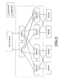
- switches 1 to 6 are Fabric switches, and a Fabric is constructed by these switches.
- the switches 1 and 2 are connected to a core network, and the switches 3 to 6 are connected to servers or storages.
- the switches 1 to 6 are connected to each other.
- a port illustrated by a circle on each switch represents an outer port connected to the core network or the servers, and a port illustrated by a quadrilateral on each switch represents an inner port connecting between the Fabric switches.
- an inner port is shown as a special interface for exchanging information inside while an outer port is shown as an ordinary switch port.
- a setting of an inner port or an outer port is carried out individually according to configuration. For example, when all ports are set as inner ports by default, it is impossible to communicate even if the ports are connected to external apparatuses or the like because they are not outer ports. For example, as illustrated in FIG. 3 , it is impossible to communicate as it is because the ports included in the port group A of the switches 1 and 2, which is connected to the core network, and the ports included in the port group B of the switches 3 to 6, which is connected to the servers, are initially set as inner ports. Therefore, initial setting processing becomes complex because the setting of the ports of the switches 1 to 6 are changed.
- the ports are defined as outer ports although physical connections between ports were carried out as inner ports (namely, when wrong setting occurs), it means direct connection between ports in the same switch because Fabric is logically considered to be one switch. In other words, a loop of layer 2 occurs, and it is impossible to stop the loop until the connections are removed, or the definition is modified.
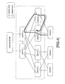
- lines are connected between the outer ports due to connection error or the like although ports are set as outer ports and are scheduled to connect to external apparatuses as illustrated by thick line arrows in FIG. 4 (that is, when wrong connection occurs), aloop occurs similarly and it influences communication performance in Fabric.
- an object of this technique is to provide a technique for automating setting of Fabric switches.
- a switch includes relating to this technique includes: (A) plural ports each of which is connected to another apparatus; (B) a determination unit that determines, for each of the plural ports, whether the port is connected to one of plural switches integrated logically; and (C) a setting unit that sets, for each of the plural ports, a port type or propriety of use based on a result of determination by the determination unit.
- the switches 1 to 6 confirm whether a connection destination of each port is a Fabric switch or not in spite of the port setting as schematically illustrated by an array of FIG. 5 . Then, because it is possible to confirm that the connection destination of a port group E of the switches 1 and 2 and the connection destination of a port group F of the switches 3 to 6 are the Fabric switches, the ports are set as inner ports. If the ports are originally set as inner ports, the port groups E and F shift to a usable state.
- connection destination of a port group C including ports of the switches 1 and 2, which is connected to the core network, and the connection destination of a port group D including ports of the switches 3 to 6, which is connected to the servers and similar, are not the Fabric switches, they are set as outer ports. It means a shift from the state of FIG. 5 to the state of FIG. 6 . If the ports are originally set as outer ports, the port groups C and D shift to a usable state.
- the port When each port is set as an inner port or an outer port in advance and a port type that is different from the port type set in advance is identified, the port may be set as it is identified, or blocking (namely, an unusable state) may be set.
- blocking namely, an unusable state
- a port is identified as an outer port although the port is set as an inner port and when a case that a port is identified as an inner port although the port is set as an outer port, the port may be set as it is identified or the blocking may be set by a different policy.
- FIG. 7 illustrates an example of configuration of a Fabric switch 100 relating to this embodiment.
- the Fabric switch 100 includes a controller 110, a memory 120, switch hardware 130, and ports 1 to n.
- the controller 110 controls whole of the Fabric switch 100 including the switch hardware 130, and includes a determination unit 111 that executes determination processing for a port type and a setting unit 112 that executes setting processing for a port through the switch hardware 130.
- the controller 110 is realized by a combination of a processor and programs, for example. In this case, the programs stored in the memory 120 or other ROMs (Read Only Memory) are executed by the processor, and the controller 110 is realized.
- the memory 120 stores data or the like used in processing executed by the controller 110.
- the switch hardware 130 is a semiconductor apparatus that communicates with other Fabric switches by its original format and that relays frames between ports.
- the ports 1 to n are connected with cables that connect other Fabric switches, external networks, servers, or the like.
- this processing is executed when the Fabric switch 100 is booted. However, when only a specified port is made to be in a state of link up, or when a definition of a port type is changed for only the specified port, this processing is executed for the specified port.
- ports are set as illustrated in FIG. 8 .
- a port type is set for each port as illustrated in the example of FIG. 8 .
- a setting about whether actual connections are prioritized or the blocking is set when a port which has been defined as an inner port is identified as an outer port (namely, whenadefinition conflict occurs) and a setting about whether actual connection is prioritized or the blocking is set when a port which has been defined as an outer port is identified as an inner port (namely, whenadefinition conflict occurs) are stored in the memory 120 as illustrated in FIG. 9 .
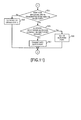
- the controller 110 causes each port on the Fabric switch 100 to be in a state of link up through the switch hardware 130, transmits LLDP (Link Layer Discovery Protocol) frame to each port, and obtains addresses of adjacent apparatuses connected to each port ( FIG. 10 : step S1).
- LLDP Link Layer Discovery Protocol
- the determination unit 111 included in the controller 110 identifies an unprocessed port (step S3), and transmits an inquiry about whether it is a Fabric switch to the address obtained for the port by a format interpretable by the Fabric switch (step S5) .
- the switch hardware 130 has a function to communicate with other Fabric switches by its original format, the determination unit 111 let the switch hardware 130 to transmit the inquiry.
- the Fabric switch which is a connection destination receives the inquiry through a pertinent port and the switch hardware 130, and the controller 110 replies to the inquiry similarly through the switch hardware 130 and the pertinent port.
- the determination unit 111 determines whether the reply to the inquiry from the identified port is obtained (step S7). When it is determined that the reply is not obtained within a predetermined time, the processing shifts to the processing of FIG. 11 through a terminal A. No reply means that the port is connected to an external apparatuses that cannot understand the inquiry.
- the determination unit 111 determines whether a port type of the port for which the inquiry is transmitted is defined as an outer port (step S8). Because obtaining the reply means that the port is connected to the Fabric switch, a definition conflict exists when the port type is defined as an outer port.
- step S8 No route
- the setting unit 112 sets the port for which the inquiry is transmitted as a usable state as it is (step S17). Then, the processing shifts to the step S15.
- the port is used as an inner port. This means there was no problem for connections, and the port can be used as it is.
- step S8 Yes route
- the setting unit 112 determines whether there's a setting that the blocking is set when a definition conflict for the outer port occurs (step S9) .
- step S9 No route
- the setting unit 112 changes the port type of the port for which the inquiry is transmitted into an inner port (step S11).
- the setting is preferably changed according to the actual connections. Then, the processing shifts to the step S15.
- the setting unit 112 set the port for which the inquiry is transmitted as a blocking port (step S13).
- the port is set as the unusable state. Because a problem like a loop can occur when connections are wrong, the port is preferably set as the blocking port. Then, the processing shifts to the step S15.
- the determination unit 111 determines whether there is an unprocessed port (step S15), and the processing returns to the step S3 when it is determined that there is an unprocessed port. On the other hand, when it is determined that there is no unprocessed port, the processing ends.
- the determination unit 111 determines whether the port type of the port for which the inquiry is transmitted is defined as an inner port (step S21). Because no reply within the predetermined time means that the port is connected to an external apparatus, a definition conflict exists when the port type is defined as an inner port.
- step S21 When it is determined that the port type is defined as an outer port (step S21: No route), the setting unit 112 set the port for which the inquiry is transmitted to a usable state as it is (step S23) . Then, the processing returns to the step S15 of FIG. 10 through a terminal B.
- the setting unit 112 determines whether there's a setting that the blocking is set when a definition conflict for the inner port occurs (step S25) .
- the setting unit 112 changes the port type of the port for which the inquiry is transmitted into an outer port (step S27) .
- the setting may preferably be changed according to the actual connection. Then, the processing shifts to the step S15 of FIG. 10 through the terminal B.
- the setting unit 112 sets the port for which the inquiry is transmitted as the blocking port (step S29) .
- the port is set as an unusable state. Because there is a possibility that a problem like a loop occurs when connections are wrong, the port may preferably be set as the blocking port. Then, the processing shifts to the step S15 of FIG. 10 through the terminal B.
- the blocking is preferable when a definition conflict occurs, it is possible to perform the blocking. Furthermore, setting may preferably be performed based only on actual connections. Furthermore, other method than the method as described above may be used to confirm whether an adjacent apparatus is a Fabric switch or not.
- the functional block diagram of the controller 110 in the Fabric switch 100 is a mere example, and the configuration in the functional block diagram does not always correspond to actual program module configuration.
- the aforementioned Fabric switch 100 is a computer apparatus as illustrated in FIG. 12 , a memory 2601, CPU 2603, Hard Disk Drive (HDD) 2605, display controller 2607 to be coupled with a display device 2609, drive device 2613 for a removable disk 2611, input unit 2615 and communication controllers 2617 (2617a to 2617c in FIG. 12 ) for coupling to a network may be coupled with a bus 2619.
- the display controller 2607, display device 2609, drive device 2613 and input unit 2615 may not be included.
- the OS and application programs for carrying out a processing in these embodiments are stored in the HDD 2605, and read out from the HDD 2605 to the memory 2601 when being executed by the CPU 2603.
- the CPU 2603 controls the display controller 2607, communication controller 2617 and drive device 2613 to carry out necessary operations.
- data that was inputted through any one of the communication controllers 2617 is outputted through another communication controller 2617.
- the CPU 2603 controls the communication controllers 2617 to appropriately switch output destinations.
- data during the processing is stored in the memory 2601, and stored in the HDD 2605 if necessary.
- the application programs for carrying out the aforementioned processing are distributed by a computer-readable removable disk 2611 storing the application programs, and the application programs are installed into the HDD 2605 through the drive device 2613.
- the programs may be installed into the HDD 2605 through the communication controller 2617 and the network such as the Internet.
- Such a computer apparatus realizes the aforementioned various functions by cooperating the hardware such as the CPU 2603 , memory 2601 and the like with the OS and the application programs if necessary.
- a switch relating to this embodiment includes: a memory; and a processor configured to use the memory and execute a process. And the process includes: determining, for each of plural ports each of which is connected to another apparatus, whether the port is connected to one of plural switches integrated logically; and setting, for each of the plural ports, a port type or propriety of use based on a result of the determining. By doing this, it becomes possible to automate setting of a Fabric switch.
- the determining may include: transmitting, for each of the plural ports, an inquiry that can be interpreted by the plural switches integrated logically; and determining, for each of the plural ports, whether a reply to the inquiry was obtained. Because the Fabric switch communicates using a predetermined format among Fabric switches logically integrated, the Fabric switch transmits the inquiry by the predetermined format. Then, it becomes possible to distinguishbecause apparatuses other than the Fabric switch cannot reply to the inquiry.
- the setting may include: setting a port type of a first port for which the reply was obtained as a first port type that is a port type of a port connected to the plural switches integrated logically.
- the setting may include: setting a port type of a second port for which the reply was not obtained as a second port type that is a port type of a port connected to an external apparatus or an external network. It becomes possible to automatically set when it is preferable to set according to actual connections. In other words, it becomes possible to avoid a problem on constructing the Fabric due to definition errors and wrong connections, and to prevent the loop occurring.
- the setting may include: upon detecting that a port type of a first port for which the reply was obtained is set as a first port type that is a port type of a port connected to an external apparatus or an external network, causing the first port to be in an unusable state.
- the setting may include: upon detecting that a port type of a second port for which the reply was not obtained is set as a second port type that is a port type of a port connected to the plurality of switches integrated logically in advance, causing the second port to be in the unusable state. It becomes possible to avoid errors on constructing the Fabric due to the wrong connections and to prevent the loop occurring.
- the setting may include: upon detecting that a port type of a first port for which the reply was obtained is set as a first port type that is a port type of a port connected to the plurality of switches integrated logically in advance, causing the first port to be in an usable state; and upon detecting that a port type of a second port for which the reply was not obtained is set as a second port type that is a port type of a port connected to an external apparatus or an external network, causing the second port to be in the usable state.
- a program causing a processor to execute the aforementioned processing, and such a program is stored in a computer readable storage medium or storage device such as a flexible disk, CD-ROM, DVD-ROM, magneto-optic disk, a semiconductor memory, and hard disk.
- a computer readable storage medium or storage device such as a flexible disk, CD-ROM, DVD-ROM, magneto-optic disk, a semiconductor memory, and hard disk.
- the intermediate processing result is temporarily stored in a storage device such as a main memory or the like.
Landscapes
- Engineering & Computer Science (AREA)
- Computer Networks & Wireless Communication (AREA)
- Signal Processing (AREA)
- Environmental & Geological Engineering (AREA)
- Small-Scale Networks (AREA)
Abstract
Description
- This technique relates to a technique for setting switches automatically.
- In a cloud service realized in recent data centers or the like, a large number of servers are deployed, and server resources are shared with a large number of customers. Therefore, also in a network directly connected to a large number of servers that has been arranged, a redundant network is to be constructed by arranging a large number of switches and setting plural routes to increase bandwidth.
- Because a switch at the previous stage of a server is in a network of
layer 2, when the redundant network is constructed as it is by setting plural routes, loop configuration occurs. Therefore, it is considered to use STP (Spanning Tree Protocol) or the like. However, when using STP, there is a problem that it is impossible to increase bandwidth because the redundant routes are blocked and cannot be used for communication. Therefore, a switch which is called a Fabric switch has appeared, in which the same kind of plural switches are logically integrated. The Fabric switch can use plural lines as redundant routes by exchanging states inside. By doing so, it becomes possible to construct a redundant network with wide bandwidth without using STP. Here, Fabric represents a network that is constructed by Fabric switches. - In switches included in a Fabric, ports connecting to other switches (hereinafter referred to as inner ports) and ports connecting to servers, terminals and other network apparatuses (hereinafter referred to as outer ports) are physically fixed or are defined for each port (an inner port or an outer port is defined for each port), and it is general to construct the Fabric based on them because this Fabric switch logically and virtually integrates plural switches into one.
- For example, as illustrated in
FIG. 1 ,switches 1 to 6 are Fabric switches, and a Fabric is constructed by these switches. Theswitches switches 3 to 6 are connected to servers or storages. Theswitches 1 to 6 are connected to each other. Then, a port illustrated by a circle on each switch represents an outer port connected to the core network or the servers, and a port illustrated by a quadrilateral on each switch represents an inner port connecting between the Fabric switches. - This is because plural lines are effectively used between inner ports, and an inner port is shown as a special interface for exchanging information inside while an outer port is shown as an ordinary switch port.
- However, in a Fabric switch that physically distinguishes an inner port from an outer port, it becomes impossible not only to operate the Fabric switch but also to construct Fabric when external apparatuses are connected to inner ports, or other Fabric switches are connected to outer ports, namely, when wrong connections occur. In the example illustrated in
FIG. 2 , it is impossible for theswitch 6 to communicate withswitches switch 6 is connected to theswitch switch 6. It takes time to investigate and to handle such connection errors and setting errors. - Moreover, in a Fabric switch whose port is set as an inner port or an outer port by a definition, a setting of an inner port or an outer port is carried out individually according to configuration. For example, when all ports are set as inner ports by default, it is impossible to communicate even if the ports are connected to external apparatuses or the like because they are not outer ports. For example, as illustrated in
FIG. 3 , it is impossible to communicate as it is because the ports included in the port group A of theswitches switches 3 to 6, which is connected to the servers, are initially set as inner ports. Therefore, initial setting processing becomes complex because the setting of the ports of theswitches 1 to 6 are changed. - Furthermore, when the ports are defined as outer ports although physical connections between ports were carried out as inner ports (namely, when wrong setting occurs), it means direct connection between ports in the same switch because Fabric is logically considered to be one switch. In other words, a loop of
layer 2 occurs, and it is impossible to stop the loop until the connections are removed, or the definition is modified. Moreover, when lines are connected between the outer ports due to connection error or the like although ports are set as outer ports and are scheduled to connect to external apparatuses as illustrated by thick line arrows inFIG. 4 (that is, when wrong connection occurs), aloop occurs similarly and it influences communication performance in Fabric. - When Fabric switch is applied to a large scale system, the number of switches increases, and a possibility of wrong connection and definition errors dramatically increase. Then, it is a big problem for construction of a system if the loop occurs due to the wrong connection or the definition error and a state of no communication continues for a long time by them, because it is difficult to check the Fabric.
-
- Patent Document 1:
Japanese Laid-open Patent Publication No. 11-252181 - Patent Document 2:
Japanese Laid-open Patent Publication No. 2000-196626 - Therefore, as one aspect, an object of this technique is to provide a technique for automating setting of Fabric switches.
- A switch includes relating to this technique includes: (A) plural ports each of which is connected to another apparatus; (B) a determination unit that determines, for each of the plural ports, whether the port is connected to one of plural switches integrated logically; and (C) a setting unit that sets, for each of the plural ports, a port type or propriety of use based on a result of determination by the determination unit.
-
-
FIG. 1 is a diagram explaining Fabric; -
FIG. 2 is a diagram explaining a conventional problem; -
FIG. 3 is a diagram explaining a conventional problem; -
FIG. 4 is a diagram explaining a conventional problem; -
FIG. 5 is a diagram explaining operation of this embodiment; -
FIG. 6 is a diagram explaining operation of this embodiment; -
FIG. 7 is a diagram depicting configuration of a Fabric switch relating to this embodiment; -
FIG. 8 is a diagram depicting an example of a port type setting; -
FIG. 9 is a diagram depicting an example of a setting policy when a definition conflict occurs; -
FIG. 10 is a diagram depicting a processing flow for operation of a Fabric switch relating to this embodiment; -
FIG. 11 is a diagram depicting a processing flow for operation of a Fabric switch relating to this embodiment; and -
FIG. 12 is a functional block diagram for a case that a switch is implemented by a computer. - In embodiments of this technique, after the
switches 1 to 6 which are Fabric switches are physically connected to each other, or the setting of the switches is changed, theswitches 1 to 6 confirm whether a connection destination of each port is a Fabric switch or not in spite of the port setting as schematically illustrated by an array ofFIG. 5 . Then, because it is possible to confirm that the connection destination of a port group E of theswitches switches 3 to 6 are the Fabric switches, the ports are set as inner ports. If the ports are originally set as inner ports, the port groups E and F shift to a usable state. - On the other hand, because it is confirmed that the connection destination of a port group C including ports of the
switches switches 3 to 6, which is connected to the servers and similar, are not the Fabric switches, they are set as outer ports. It means a shift from the state ofFIG. 5 to the state ofFIG. 6 . If the ports are originally set as outer ports, the port groups C and D shift to a usable state. - When each port is set as an inner port or an outer port in advance and a port type that is different from the port type set in advance is identified, the port may be set as it is identified, or blocking (namely, an unusable state) may be set. When a port is identified as an outer port although the port is set as an inner port and when a case that a port is identified as an inner port although the port is set as an outer port, the port may be set as it is identified or the blocking may be set by a different policy.
- In the following, configuration and operation of a Fabric switch to execute such operation will be specifically explained.
-
FIG. 7 illustrates an example of configuration of aFabric switch 100 relating to this embodiment. TheFabric switch 100 includes acontroller 110, amemory 120,switch hardware 130, andports 1 to n. Thecontroller 110 controls whole of theFabric switch 100 including theswitch hardware 130, and includes adetermination unit 111 that executes determination processing for a port type and asetting unit 112 that executes setting processing for a port through theswitch hardware 130. Thecontroller 110 is realized by a combination of a processor and programs, for example. In this case, the programs stored in thememory 120 or other ROMs (Read Only Memory) are executed by the processor, and thecontroller 110 is realized. Thememory 120 stores data or the like used in processing executed by thecontroller 110. - The
switch hardware 130 is a semiconductor apparatus that communicates with other Fabric switches by its original format and that relays frames between ports. Theports 1 to n are connected with cables that connect other Fabric switches, external networks, servers, or the like. - Next, by using
FIGs. 8 to 11 , detail of the processing executed by theFabric switch 100 relating to this embodiment will be explained. - For example, this processing is executed when the
Fabric switch 100 is booted. However, when only a specified port is made to be in a state of link up, or when a definition of a port type is changed for only the specified port, this processing is executed for the specified port. - For example, assume that ports are set as illustrated in
FIG. 8 . A port type is set for each port as illustrated in the example ofFIG. 8 . For example, there are not only a case that a port type is directly set for each port of theports 1 to n but also a case that the same data as the example ofFIG. 8 is stored in thememory 120. Furthermore, a setting about whether actual connections are prioritized or the blocking is set when a port which has been defined as an inner port is identified as an outer port (namely, whenadefinition conflict occurs) and a setting about whether actual connection is prioritized or the blocking is set when a port which has been defined as an outer port is identified as an inner port (namely, whenadefinition conflict occurs) are stored in thememory 120 as illustrated inFIG. 9 . - Then, the
controller 110 causes each port on theFabric switch 100 to be in a state of link up through theswitch hardware 130, transmits LLDP (Link Layer Discovery Protocol) frame to each port, and obtains addresses of adjacent apparatuses connected to each port (FIG. 10 : step S1). - After that, the
determination unit 111 included in thecontroller 110 identifies an unprocessed port (step S3), and transmits an inquiry about whether it is a Fabric switch to the address obtained for the port by a format interpretable by the Fabric switch (step S5) . As described above, because theswitch hardware 130 has a function to communicate with other Fabric switches by its original format, thedetermination unit 111 let theswitch hardware 130 to transmit the inquiry. - When a port for which the inquiry is transmitted is connected to the Fabric switch, the Fabric switch which is a connection destination receives the inquiry through a pertinent port and the
switch hardware 130, and thecontroller 110 replies to the inquiry similarly through theswitch hardware 130 and the pertinent port. - Thus, although the Fabric switch can reply to the inquiry when the port for which the inquiry is transmitted is connected to the Fabric switch, apparatuses other than the Fabric switch cannot reply to the inquiry because the apparatuses cannot understand the inquiry. Therefore, the
determination unit 111 determines whether the reply to the inquiry from the identified port is obtained (step S7). When it is determined that the reply is not obtained within a predetermined time, the processing shifts to the processing ofFIG. 11 through a terminal A. No reply means that the port is connected to an external apparatuses that cannot understand the inquiry. - On the other hand, when it is determined that the reply is obtained, the
determination unit 111 determines whether a port type of the port for which the inquiry is transmitted is defined as an outer port (step S8). Because obtaining the reply means that the port is connected to the Fabric switch, a definition conflict exists when the port type is defined as an outer port. - When it is determined that the port type is defined as an inner port (step S8: No route), the
setting unit 112 sets the port for which the inquiry is transmitted as a usable state as it is (step S17). Then, the processing shifts to the step S15. In other words, the port is used as an inner port. This means there was no problem for connections, and the port can be used as it is. - On the other hand, when the port type is defined as an outer port (step S8: Yes route), the
setting unit 112 determines whether there's a setting that the blocking is set when a definition conflict for the outer port occurs (step S9) . When it is determined that there' s a setting that the port is set according to the actual connections without blocking (step S9: No route), thesetting unit 112 changes the port type of the port for which the inquiry is transmitted into an inner port (step S11). Thus, when a conflict between the actual connections and the setting occurs, the setting is preferably changed according to the actual connections. Then, the processing shifts to the step S15. - On the other hand, when it is determined that there's a setting that the blocking is set, the
setting unit 112 set the port for which the inquiry is transmitted as a blocking port (step S13). In other words, the port is set as the unusable state. Because a problem like a loop can occur when connections are wrong, the port is preferably set as the blocking port. Then, the processing shifts to the step S15. - Then, the
determination unit 111 determines whether there is an unprocessed port (step S15), and the processing returns to the step S3 when it is determined that there is an unprocessed port. On the other hand, when it is determined that there is no unprocessed port, the processing ends. - Shifting to the explanation of the processing of
FIG. 11 , thedetermination unit 111 determines whether the port type of the port for which the inquiry is transmitted is defined as an inner port (step S21). Because no reply within the predetermined time means that the port is connected to an external apparatus, a definition conflict exists when the port type is defined as an inner port. - When it is determined that the port type is defined as an outer port (step S21: No route), the
setting unit 112 set the port for which the inquiry is transmitted to a usable state as it is (step S23) . Then, the processing returns to the step S15 ofFIG. 10 through a terminal B. - On the other hand, when it is determined that the port type is defined as an inner port (step S21: Yes route), the
setting unit 112 determines whether there's a setting that the blocking is set when a definition conflict for the inner port occurs (step S25) . When it is determined that there' s a setting that the port is set according to the actual connection without blocking, thesetting unit 112 changes the port type of the port for which the inquiry is transmitted into an outer port (step S27) . Thus, when the conflict between the actual connections and the setting, the setting may preferably be changed according to the actual connection. Then, the processing shifts to the step S15 ofFIG. 10 through the terminal B. - On the other hand, when it is determined that there's a setting that the blocking is set, the
setting unit 112 sets the port for which the inquiry is transmitted as the blocking port (step S29) . In other words, the port is set as an unusable state. Because there is a possibility that a problem like a loop occurs when connections are wrong, the port may preferably be set as the blocking port. Then, the processing shifts to the step S15 ofFIG. 10 through the terminal B. - By executing the processing as described above, it is possible to automatically set a port type based on actual connections regardless of initial setting.
- In a network peripheral to servers deployed in a data center and a network of a general server system, the number of switches deployed on the preceding stage of servers increases as the number of the servers which have been deployed increases. Then, even if management is simplified by logically showing a switch as a Fabric switch, it takes time to detect a cause of a problem and an introduction cost increases, because it is difficult to decrease connection errors and port definition errors and a system operates even if there are a few definition errors. However, it becomes possible to reduce a cost by executing the processing described above.
- However, if the blocking is preferable when a definition conflict occurs, it is possible to perform the blocking. Furthermore, setting may preferably be performed based only on actual connections. Furthermore, other method than the method as described above may be used to confirm whether an adjacent apparatus is a Fabric switch or not.
- Although the embodiment of this technique was explained above, this technique is not limited to those. For example, the functional block diagram of the
controller 110 in theFabric switch 100 is a mere example, and the configuration in the functional block diagram does not always correspond to actual program module configuration. - As for the processing flow, as long as the processing results do not change, the turns of the steps may be exchanged or the steps may be executed in parallel.
- In addition, the
aforementioned Fabric switch 100 is a computer apparatus as illustrated inFIG. 12 , amemory 2601,CPU 2603, Hard Disk Drive (HDD) 2605,display controller 2607 to be coupled with adisplay device 2609,drive device 2613 for aremovable disk 2611,input unit 2615 and communication controllers 2617 (2617a to 2617c inFIG. 12 ) for coupling to a network may be coupled with abus 2619. Incidentally, according to circumstances, thedisplay controller 2607,display device 2609,drive device 2613 andinput unit 2615 may not be included. The OS and application programs for carrying out a processing in these embodiments are stored in theHDD 2605, and read out from theHDD 2605 to thememory 2601 when being executed by theCPU 2603. If necessary, theCPU 2603 controls thedisplay controller 2607, communication controller 2617 and drivedevice 2613 to carry out necessary operations. Incidentally, data that was inputted through any one of the communication controllers 2617 is outputted through another communication controller 2617. TheCPU 2603 controls the communication controllers 2617 to appropriately switch output destinations. In addition, data during the processing is stored in thememory 2601, and stored in theHDD 2605 if necessary. In the embodiments of this technique, the application programs for carrying out the aforementioned processing are distributed by a computer-readableremovable disk 2611 storing the application programs, and the application programs are installed into theHDD 2605 through thedrive device 2613. The programs may be installed into theHDD 2605 through the communication controller 2617 and the network such as the Internet. Such a computer apparatus realizes the aforementioned various functions by cooperating the hardware such as theCPU 2603 ,memory 2601 and the like with the OS and the application programs if necessary. - The aforementioned embodiment is summarized as follows:
- A switch relating to this embodiment includes: a memory; and a processor configured to use the memory and execute a process. And the process includes: determining, for each of plural ports each of which is connected to another apparatus, whether the port is connected to one of plural switches integrated logically; and setting, for each of the plural ports, a port type or propriety of use based on a result of the determining. By doing this, it becomes possible to automate setting of a Fabric switch.
- Moreover, the determining may include: transmitting, for each of the plural ports, an inquiry that can be interpreted by the plural switches integrated logically; and determining, for each of the plural ports, whether a reply to the inquiry was obtained. Because the Fabric switch communicates using a predetermined format among Fabric switches logically integrated, the Fabric switch transmits the inquiry by the predetermined format. Then, it becomes possible to distinguishbecause apparatuses other than the Fabric switch cannot reply to the inquiry.
- Furthermore, the setting may include: setting a port type of a first port for which the reply was obtained as a first port type that is a port type of a port connected to the plural switches integrated logically. Moreover, the setting may include: setting a port type of a second port for which the reply was not obtained as a second port type that is a port type of a port connected to an external apparatus or an external network. It becomes possible to automatically set when it is preferable to set according to actual connections. In other words, it becomes possible to avoid a problem on constructing the Fabric due to definition errors and wrong connections, and to prevent the loop occurring.
- Furthermore, the setting may include: upon detecting that a port type of a first port for which the reply was obtained is set as a first port type that is a port type of a port connected to an external apparatus or an external network, causing the first port to be in an unusable state. Moreover, the setting may include: upon detecting that a port type of a second port for which the reply was not obtained is set as a second port type that is a port type of a port connected to the plurality of switches integrated logically in advance, causing the second port to be in the unusable state. It becomes possible to avoid errors on constructing the Fabric due to the wrong connections and to prevent the loop occurring.
- Moreover, the setting may include: upon detecting that a port type of a first port for which the reply was obtained is set as a first port type that is a port type of a port connected to the plurality of switches integrated logically in advance, causing the first port to be in an usable state; and upon detecting that a port type of a second port for which the reply was not obtained is set as a second port type that is a port type of a port connected to an external apparatus or an external network, causing the second port to be in the usable state.
- Incidentally, it is possible to create a program causing a processor to execute the aforementioned processing, and such a program is stored in a computer readable storage medium or storage device such as a flexible disk, CD-ROM, DVD-ROM, magneto-optic disk, a semiconductor memory, and hard disk. In addition, the intermediate processing result is temporarily stored in a storage device such as a main memory or the like.
Claims (8)
- A switch, comprising:a plurality of ports each of which is connected to another apparatus;a determination unit that determines, for eachof the plurality of ports, whether the port is connected to one of a plurality of switches integrated logically; anda setting unit that sets, for each of the plurality of ports, a port type or propriety of use based on a result of determination by the determination unit.
- The switch as set forth in claim 1, wherein the determination unit comprises:transmitting, for each of the plurality of ports, an inquiry that can be interpreted by the plurality of switches integrated logically; anddetermining, for each of the plurality of ports, whether a reply to the inquiry was obtained.
- The switch as set forth in claim 2, wherein the setting comprises:setting a port type of a first port for which the reply was obtained as a first port type that is a port type of a port connected to the plurality of switches integrated logically.
- The switch as set forth in claim 2 or 3, wherein the setting comprises:setting a port type of a second port for which the reply was not obtained as a second port type that is a port type of a port connected to an external apparatus or an external network.
- The switch as set forth in claim 2, wherein the setting comprises:upon detecting that a port type of a first port for which the reply was obtained is set as a first port type that is a port type of a port connected to an external apparatus or an external network, causing the first port to be in an unusable state.
- The switch as set forth in claim 5, wherein the setting comprises:upon detecting that a port type of a second port for which the reply was not obtained is set as a second port type that is a port type of a port connected to the plurality of switches integrated logically in advance, causing the second port to be in the unusable state.
- The switch as set forth in claim 2, 5, or 6, wherein the setting comprises:upon detecting that a port type of a first port for which the reply was obtained is set as a first port type that is a port type of a port connected to the plurality of switches integrated logically in advance, causing the first port to be in an usable state; andupon detecting that a port type of a second port for which the reply was not obtained is set as a second port type that is a port type of a port connected to an external apparatus or an external network, causing the second port to be in the usable state.
- A program for executing a process comprising:determining, for each of a plurality of ports, whether the port is connected to one of a plurality of switches integrated logically; andsetting, for each of the plurality of ports, a port type or propriety of use based on a result of the determining.
Applications Claiming Priority (1)
| Application Number | Priority Date | Filing Date | Title |
|---|---|---|---|
| PCT/JP2013/054163 WO2014128859A1 (en) | 2013-02-20 | 2013-02-20 | Switch and program |
Publications (2)
| Publication Number | Publication Date |
|---|---|
| EP2961108A1 true EP2961108A1 (en) | 2015-12-30 |
| EP2961108A4 EP2961108A4 (en) | 2016-03-09 |
Family
ID=51390692
Family Applications (1)
| Application Number | Title | Priority Date | Filing Date |
|---|---|---|---|
| EP13876023.6A Withdrawn EP2961108A4 (en) | 2013-02-20 | 2013-02-20 | SWITCH AND PROGRAM |
Country Status (4)
| Country | Link |
|---|---|
| US (1) | US9742698B2 (en) |
| EP (1) | EP2961108A4 (en) |
| JP (1) | JP6004079B2 (en) |
| WO (1) | WO2014128859A1 (en) |
Families Citing this family (9)
| Publication number | Priority date | Publication date | Assignee | Title |
|---|---|---|---|---|
| WO2014147746A1 (en) * | 2013-03-19 | 2014-09-25 | 富士通株式会社 | Switch and program |
| US9654852B2 (en) * | 2013-12-24 | 2017-05-16 | Nec Corporation | Scalable hybrid packet/circuit switching network architecture |
| KR102189748B1 (en) * | 2014-03-29 | 2020-12-14 | 주식회사 쏠리드 | Point-to-multipoint communication system capable of automatic id allocation |
| US10158929B1 (en) * | 2017-02-17 | 2018-12-18 | Capital Com SV Investments Limited | Specialized optical switches utilized to reduce latency in switching between hardware devices in computer systems and methods of use thereof |
| US10785118B2 (en) * | 2017-02-23 | 2020-09-22 | Dell Products L.P. | Systems and methods for network topology validation |
| US10425287B2 (en) | 2017-02-23 | 2019-09-24 | Dell Products L.P. | Systems and methods for network topology discovery |
| US10615902B2 (en) * | 2018-06-11 | 2020-04-07 | Delta Electronics, Inc. | Intelligence-defined optical tunnel network system and network system control method |
| US10623101B1 (en) | 2018-08-07 | 2020-04-14 | Hewlett Packard Enterprise Development Lp | Hyperscale photonics connectivity solution |
| US10757041B2 (en) * | 2018-12-03 | 2020-08-25 | Hewlett Packard Enterprise Development Lp | Full server-level redundancy using a single network interface controller(NIC) and a single NIC card |
Family Cites Families (17)
| Publication number | Priority date | Publication date | Assignee | Title |
|---|---|---|---|---|
| JPH1084355A (en) * | 1996-09-10 | 1998-03-31 | Hitachi Cable Ltd | Switching hub |
| US6430182B1 (en) | 1997-10-16 | 2002-08-06 | Nec Corporation | Fabric system and method for assigning identifier for fabric apparatus therefor |
| JP3107064B2 (en) | 1997-10-16 | 2000-11-06 | 日本電気株式会社 | Fabric system and method for assigning identifiers to fabric devices |
| JP3075276B2 (en) | 1998-12-28 | 2000-08-14 | 日本電気株式会社 | Fiber Channel fabric and fabric ports |
| US6381643B1 (en) * | 1999-11-08 | 2002-04-30 | International Business Machines Corporation | Mechanism and procedure for detecting switch mis-cabling |
| US20020156888A1 (en) * | 2001-04-23 | 2002-10-24 | Lee Man-Ho L. | Method and apparatus for detecting and reporting configuration errors in a multi-component switching fabric |
| JP3822083B2 (en) * | 2001-10-03 | 2006-09-13 | 富士通株式会社 | Transmission equipment |
| US8320241B2 (en) * | 2002-07-30 | 2012-11-27 | Brocade Communications System, Inc. | Fibre channel network employing registered state change notifications with enhanced payload |
| JP2005318086A (en) * | 2004-04-27 | 2005-11-10 | Fujitsu Ltd | Transmission equipment |
| JP2006338374A (en) * | 2005-06-02 | 2006-12-14 | Fujitsu Ltd | Network connection management device and network connection management method |
| US20070183337A1 (en) * | 2006-02-03 | 2007-08-09 | International Business Machines Corporation | FC-AL cabling management system |
| US7698408B1 (en) * | 2006-07-24 | 2010-04-13 | Oracle America, Inc. | Method and apparatus for testing a network |
| JP2009290332A (en) | 2008-05-27 | 2009-12-10 | Fujitsu Ltd | Transmission device having connection confirmation function |
| US9363208B1 (en) * | 2011-03-29 | 2016-06-07 | Amazon Technologies, Inc. | Logical switches |
| JP5794011B2 (en) | 2011-07-19 | 2015-10-14 | 富士通株式会社 | Network management apparatus and network management method |
| US8938528B2 (en) * | 2011-11-08 | 2015-01-20 | Hitachi, Ltd. | Computer system, and method for managing resource pool information |
| US9083613B2 (en) * | 2012-10-16 | 2015-07-14 | Cisco Technology, Inc. | Detection of cabling error in communication network |
-
2013
- 2013-02-20 JP JP2015501136A patent/JP6004079B2/en active Active
- 2013-02-20 WO PCT/JP2013/054163 patent/WO2014128859A1/en not_active Ceased
- 2013-02-20 EP EP13876023.6A patent/EP2961108A4/en not_active Withdrawn
-
2015
- 2015-07-23 US US14/806,724 patent/US9742698B2/en not_active Expired - Fee Related
Also Published As
| Publication number | Publication date |
|---|---|
| WO2014128859A1 (en) | 2014-08-28 |
| US9742698B2 (en) | 2017-08-22 |
| JPWO2014128859A1 (en) | 2017-02-02 |
| JP6004079B2 (en) | 2016-10-05 |
| EP2961108A4 (en) | 2016-03-09 |
| US20150326502A1 (en) | 2015-11-12 |
Similar Documents
| Publication | Publication Date | Title |
|---|---|---|
| US9742698B2 (en) | Switch and setting method | |
| US9231849B2 (en) | Apparatus and method for controlling virtual switches | |
| JP3640187B2 (en) | Fault processing method for multiprocessor system, multiprocessor system and node | |
| US7904744B2 (en) | Data storage using multiple protocols | |
| US20160352578A1 (en) | System and method for adaptive paths locator for virtual network function links | |
| US20160342510A1 (en) | Remote management of data planes and configuration of networking devices | |
| EP2915285B1 (en) | Adding device-wide capabilities and parameters to split-architecture devices | |
| US10050906B2 (en) | Virtual node having separate control and data planes | |
| US11368356B2 (en) | Computer having an embedded switch | |
| EP2717169B1 (en) | Administration device, information processing device, and data transfer method | |
| EP3125478B1 (en) | Method, device, and system for determining intermediate routing node | |
| US20200145281A1 (en) | Using an out-of-band network to reconfigure a bus interface port | |
| CN111338676A (en) | A BMC firmware upgrade system and method with both in-band and out-of-band modes | |
| US20140359114A1 (en) | Computer-readable recording medium, usage mode data generation method, and usage mode data generation device | |
| WO2026045730A1 (en) | Data transmission methods and apparatuses, and electronic device, computer-readable storage medium and computer program product | |
| CN110532202A (en) | A storage cluster system, data transmission method and device | |
| US20140022937A1 (en) | Integrated device management over ethernet network | |
| CN110324202B (en) | Method and device for detecting line quality | |
| US10097450B2 (en) | Relay device, configuration method, and recording medium | |
| US9515846B2 (en) | Switch and setting method | |
| US10574516B2 (en) | Management apparatus and shared network system | |
| US20170180232A1 (en) | Apparatus and method for setting bandwidth | |
| US12035212B2 (en) | Wireless communication device and control method for wireless communication device | |
| CN110018839B (en) | Hardware accelerator multiplexing method and hardware accelerator | |
| CN117880368A (en) | Network traffic forwarding method, device, equipment and storage medium based on Jenkins |
Legal Events
| Date | Code | Title | Description |
|---|---|---|---|
| PUAI | Public reference made under article 153(3) epc to a published international application that has entered the european phase |
Free format text: ORIGINAL CODE: 0009012 |
|
| 17P | Request for examination filed |
Effective date: 20150804 |
|
| AK | Designated contracting states |
Kind code of ref document: A1 Designated state(s): AL AT BE BG CH CY CZ DE DK EE ES FI FR GB GR HR HU IE IS IT LI LT LU LV MC MK MT NL NO PL PT RO RS SE SI SK SM TR |
|
| AX | Request for extension of the european patent |
Extension state: BA ME |
|
| A4 | Supplementary search report drawn up and despatched |
Effective date: 20160204 |
|
| RIC1 | Information provided on ipc code assigned before grant |
Ipc: H04L 12/46 20060101AFI20160129BHEP Ipc: H04L 12/933 20130101ALI20160129BHEP |
|
| DAX | Request for extension of the european patent (deleted) | ||
| 17Q | First examination report despatched |
Effective date: 20171030 |
|
| STAA | Information on the status of an ep patent application or granted ep patent |
Free format text: STATUS: THE APPLICATION IS DEEMED TO BE WITHDRAWN |
|
| 18D | Application deemed to be withdrawn |
Effective date: 20190528 |