EP2961107A1 - Switch and program - Google Patents
Switch and program Download PDFInfo
- Publication number
- EP2961107A1 EP2961107A1 EP13875498.1A EP13875498A EP2961107A1 EP 2961107 A1 EP2961107 A1 EP 2961107A1 EP 13875498 A EP13875498 A EP 13875498A EP 2961107 A1 EP2961107 A1 EP 2961107A1
- Authority
- EP
- European Patent Office
- Prior art keywords
- port
- setting
- switch
- vlan
- switches
- Prior art date
- Legal status (The legal status is an assumption and is not a legal conclusion. Google has not performed a legal analysis and makes no representation as to the accuracy of the status listed.)
- Withdrawn
Links
Images




Classifications
-
- H—ELECTRICITY
- H04—ELECTRIC COMMUNICATION TECHNIQUE
- H04L—TRANSMISSION OF DIGITAL INFORMATION, e.g. TELEGRAPHIC COMMUNICATION
- H04L12/00—Data switching networks
- H04L12/28—Data switching networks characterised by path configuration, e.g. LAN [Local Area Networks] or WAN [Wide Area Networks]
- H04L12/46—Interconnection of networks
- H04L12/4641—Virtual LANs, VLANs, e.g. virtual private networks [VPN]
-
- H—ELECTRICITY
- H04—ELECTRIC COMMUNICATION TECHNIQUE
- H04L—TRANSMISSION OF DIGITAL INFORMATION, e.g. TELEGRAPHIC COMMUNICATION
- H04L41/00—Arrangements for maintenance, administration or management of data switching networks, e.g. of packet switching networks
- H04L41/08—Configuration management of networks or network elements
-
- H—ELECTRICITY
- H04—ELECTRIC COMMUNICATION TECHNIQUE
- H04L—TRANSMISSION OF DIGITAL INFORMATION, e.g. TELEGRAPHIC COMMUNICATION
- H04L41/00—Arrangements for maintenance, administration or management of data switching networks, e.g. of packet switching networks
- H04L41/08—Configuration management of networks or network elements
- H04L41/0895—Configuration of virtualised networks or elements, e.g. virtualised network function or OpenFlow elements
Definitions
- the first setting processing unit 111 reads out a group number list of the specific port for which VLAN has been set from the port information table (step S9). Furthermore, the first setting processing unit 111 generates VLAN definition cooperation notification including the VLAN ID and the group number list that has been read out, and transmits it to the second setting processing unit 112 of the switch 100 and other switches (step S11). Then, the processing ends.
- the second setting processing unit 112 identifies a port of an unprocessed entry satisfying the conditions of the step S23 or the step S25, and determines whether a value of a setting counter of an entry, which has a port number of the identified port and the notified VLAN ID, is 0 in the VLAN cooperation table (step S27).
- the processing shifts to the step S31, and the second setting processing unit 112 increments the value of the setting counter for the identified port by 1 (step S31) . Then, the processing shifts to the processing of FIG. 8 through a terminal B.
- the second setting processing unit 112 determines whether there is an unprocessed entry whose port type is Inner Port in the port information table (step S35). For example, if the processing does not go through the step S25, when the step S35 is executed at first, entries whose port type is Inner Port are extracted, and a list of the entries are processed in order.
- the second applying unit may apply the setting to ports other than the first port and the second port. This is because the setting of the virtual subnetwork is used for relaying frames among switches.
Landscapes
- Engineering & Computer Science (AREA)
- Computer Networks & Wireless Communication (AREA)
- Signal Processing (AREA)
- Computer Security & Cryptography (AREA)
- Small-Scale Networks (AREA)
Abstract
Description
- This technique relates to a technique for setting switches automatically.
- Systems in data centers or companies have been integrated by cloud migration recently. As described in
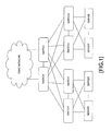
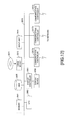
FIG. 1 , a cloud system includes virtualized servers (or storages) and network switches connecting them (hereinafter, abbreviated to switches), and is often connected to a core network (a router, a L3 (Layer 3) switch, and the like. It is also called an external network that is different from a network including switches) through the switches. - As servers are virtualized and comprehensively managed in configuration of such a cloud system, efficiency of operation is sometimes improved by virtually unifying plural switches into one and unifying control and management of plural routes.
- Here, a switch side provides networks used by each VM (Virtual Machine) as communication environment of
layer 2, because VMs that operate on servers in virtual environment are ordinarily interconnected bylayer 2. Moreover, it is general to providelayer 2 communication environment among VMs by using VLAN (Virtual Local Area Network) or the like, because the networks used by each VM (a broadcast range of layer 2) are different from each other. - In present server virtualizing systems, there are several methods that define a VLAN between a server and a port of a switch that is directly connected to the server, and a VLAN definition in a boundary point between the server and the port is automatically or manually set according to a state of a VM that is used.
- On the other hand, when servers communicate with external networks through a core network, a setting of the same VLAN as a VLAN that has been defined for ports of switches that are directly connected to the servers is applied to ports of switches that are connected to the core network. However, there is no proper method for setting a VLAN like this automatically.
-
- Patent Document 1:
Japanese Laid-open Patent Publication No. 09-284328 - Patent Document 2:
Japanese Laid-open Patent Publication No. 09-284329 - Therefore, an object of this technique is, as one aspect, to provide a technique for applying a setting of a virtual subnetwork to switches between external apparatuses and an external network automatically.
- A switch relating to this technique includes: a memory; and a processor configured to use the memory and execute a process. And the process includes: first applying a setting of a virtual subnetwork to a first port that is connected to an external apparatus, upon detecting an instruction to apply the setting to the first port; and upon detecting that the setting was applied to the first port in the switch or other switches, second applying the setting to a second port that is connected to an external network and is associated with the first port in advance.
-
-
FIG. 1 is a diagram for explaining a relationship among a core network, switches, and external apparatuses such as servers or the like; -
FIG. 2 is a diagram for explaining an outline of this embodiment; -
FIG. 3 is a diagram depicting an example of configuration of a switch relating to this embodiment; -
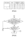
FIG. 4 is a diagram depicting an example of a port information table; -
FIG. 5 is a diagram depicting an example of a VLAN cooperation table; -
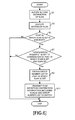
FIG. 6 is a diagram depicting a processing flow performed when defining a VLAN; -
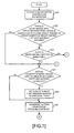
FIG. 7 is a diagram depicting a processing flow performed when receiving a VLAN definition cooperation notification; -
FIG. 8 is a diagram depicting a processing flow performed when receiving the VLAN definition cooperation notification; -
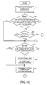
FIG. 9 is a diagram depicting a processing flow performed when deleting the VLAN definition; -
FIG. 10 is a diagram depicting a processing flow performed when receiving a VLAN deletion cooperation notification; -
FIG. 11 is a diagram depicting a processing flow performed when receiving the VLAN deletion cooperation notification; and -
FIG. 12 is a functional block diagram representing a case such that a switch is implemented by a computer. - By using
FIG. 2 , an example of a network relating to this embodiment will be explained. In this embodiment, anetwork including switches 1 to 6 is set up between a core network and external apparatuses such as servers and storages. Theswitches switches 3 to 6 include a port connected to the external apparatuses such as servers (hereinafter referred to as an End Port) and the inner port connected to other switches. - In this embodiment, a VLAN definition that has been set for end ports of the
switches FIG. 2 is reflected to a network port of theswitch 1 connected to the core network. In other words, the VLAN definition is reflected by defining the end ports and the network port surrounded by a dotted line A as one group A. On the other hand, a VLAN definition that has been set for end ports of theswitches switch 2 connected to the core network. In other words, the VLAN definition is reflected by defining the end ports and the network port surrounded by a dotted line B as one group B. An end port and a network port sometimes belong to plural groups. By defining such groups, it becomes possible to control a range to which a VLAN definition is reflected. - In this embodiment, the VLAN definition that has been set in the end ports is also reflected to inner ports. This is because Ethernet (a registered trademark) frames of each VLAN are exchanged through the inner ports among
switches 1 to 6. - Next,
FIG. 3 illustrates a functional block diagram of a switch relating to this embodiment. Aswitch 100 includes acontroller 110, amemory 120, aswitch hardware 130, andports 1 to n. Thecontroller 110 controls thewhole switch 100 including theswitch hardware 130, and includes a firstsetting processing unit 111 that changes settings of VLAN definitions for end ports of theswitch 100 and that notifies theswitch 100 and other switches, and a secondsetting processing unit 112 that changes settings of VLAN definitions for ports other than the end ports according to the notification from theswitch 100 or other switches. Thecontroller 110 is realized by, for example, a combination of a processor and programs. In this case, the programs stored in thememory 120 or other ROM (Read Only Memories) are executed by the processor and thecontroller 110 is realized. Thememory 120 stores data used in processing executed by thecontroller 110. - The
switch hardware 130 is a semiconductor apparatus that relays frames among ports. Theswitch 100 is called a Fabric switch, and may be a switch that can use plural lines as redundant routes by logically unifying plural switches of the same kinds into one switch and exchanging conditions inside. In this case, theswitch hardware 130 has a function that communicates with other Fabric switches by an original format of theswitch hardware 130. Theports 1 to n are connected with cables that connect other Fabric switches, external networks, servers, and the like. - Moreover, a port information table and a VLAN cooperation table are stored in the
memory 120.FIG. 4 illustrates an example of the port information table. In the example ofFIG. 4 , a port type (End Port / Network Port / Inner Port) and a group number list, which is a list of group numbers are registered in association with a port number. As described above, inFIG. 4 , a port whose port number is 3 belongs to both thegroup 1 and thegroup 2. On the other hand, a port whose port number is 1 and a port whose port number is 2 belong to thegroup 1 and thegroup 2, respectively. A user is able to set the port type and the group number list. For example, the user sets them by using a conventional setting interface for switch such as CLI (Command Line Interface), Web, or the like. - Moreover,
FIG. 5 illustrates an example of the VLAN cooperation table. In the example ofFIG. 5 , a VLAN ID, a cooperation possibility flag, and a setting counter are registered in association with a port number. As for a combination of the VLAN ID and the cooperation possibility flag, a user sets, for each port, for all possible combinations in advance. The cooperation possibility flag is a flag that represents whether cooperative processing for reflecting the VLAN definition to other switches when a VLAN is defined is performed or not. Moreover, an initial value of the setting counter is 0. - Moreover, each
switch 100 maintains address information of other switches (or the address information is defined in advance) to communicate with other switches. Moreover, when so-called Fabric that operates as one logical switch as a whole is provided as theswitches 1 to 6 inFIG. 2 , notification as described below may be used by using inner communication for Fabric configuration. - Next, by using
FIGs. 6 to 11 , operation of theswitch 100 will be explained. First, by usingFIG. 6 , processing of the firstsetting processing unit 111, which is performed when a VLAN is defined, will be explained. - The first
setting processing unit 111 accepts a setting instruction of VLAN for a specific port through a predetermined interface (FIG. 6 : step S1). The setting instruction of VLAN includes a VLAN ID of a VLAN to be defined. - Then, the first
setting processing unit 111 applies a setting of a VLAN to the specif ic port, for example, through the switch hardware 130 (step S3). For example, the VLAN ID is registered. - Moreover, the first
setting processing unit 111 searches the port information table by the port number of the specific port for which the VLAN has been set, and determines whether the specific port is an end port or not (step S5) . When it is determined that the specific port is not end port, the processing ends because the VLAN definition is not reflected to other ports and other switches. - On the other hand, when the specific port is an end port, the first
setting processing unit 111 determines whether "cooperation possible" is set for a combination of the specific port for which the VLAN has been set and the set VLAN ID in the VLAN cooperation table (step S7). It is determined whether the cooperation possibility flag represents that it is possible to cooperate or not. When it is determined that it is impossible to cooperate, the processing ends. - On the other hand, when it is determined that "cooperation possible" is set for the combination, the first
setting processing unit 111 reads out a group number list of the specific port for which VLAN has been set from the port information table (step S9). Furthermore, the firstsetting processing unit 111 generates VLAN definition cooperation notification including the VLAN ID and the group number list that has been read out, and transmits it to the secondsetting processing unit 112 of theswitch 100 and other switches (step S11). Then, the processing ends. - Thus, the first
setting processing unit 111 sets the VLAN definition that has been instructed for the specific port, and notifies the VLAN definition to be reflected to other switches. - Next, by using
FIGs. 7 and8 , processing performed by the secondsetting processing unit 112 that has received the VLAN definition cooperation notification will be explained. A port that has received the VLAN definition cooperation notification from other switches outputs the VLAN definition cooperation notification to the secondsetting processing unit 112 through theswitch hardware 130, for example. - When the second
setting processing unit 112 receives the VLAN definition cooperation notification (FIG. 7 : step S21), the secondsetting processing unit 112 determines whether there is an entry whose port type is Network Port, which is associated with the same group number as group number of the group number list that has been notified in the port information table (step S23). In the example ofFIG. 4 , an entry of a port whose port number is "3" is applicable when group number "1" is included in the group number list. - When it is determined that there is no entry satisfying the condition of the step S23, the second
setting processing unit 112 determines whether there is an entry whose port type is Inner Port in the port information table (step S25). In the example ofFIG. 4 , an entry of a port whose port number is "4" satisfies the condition. If there is no inner port, the processing ends through a terminal A. - On the other hand, when it is determined that there is an entry satisfying the conditions of the step S23 or the step S25, the second
setting processing unit 112 identifies a port of an unprocessed entry satisfying the conditions of the step S23 or the step S25, and determines whether a value of a setting counter of an entry, which has a port number of the identified port and the notified VLAN ID, is 0 in the VLAN cooperation table (step S27). - In the example of the network illustrated in
FIG. 2 , although four end ports of theswitches - The VLAN has not been set for the identified port yet when a value of the setting counter is 0. Therefore, the second
setting processing unit 112 applies a VLAN of the notified VLAN ID to the identified port through the switch hardware 130 (step S29). Then, the processing shifts to the step S31. - On the other hand, the VLAN has already been set when a value of the setting counter is not 0. Therefore, the processing shifts to the step S31, and the second
setting processing unit 112 increments the value of the setting counter for the identified port by 1 (step S31) . Then, the processing shifts to the processing ofFIG. 8 through a terminal B. - Shifting to the explanation of the processing of
FIG. 8 , the secondsetting processing unit 112 determines whether there is an unprocessed entry whose port type is Network Port, which is associated with the same group number as group number of the group number list that has been notified in the port information table (step S33) . For example, entries satisfying the condition of the step S23 are extracted, and it may be determined whether there is an unprocessed entry by processing a list of the entries in order. When it is determined that there is an unprocessed entry satisfying the condition of the step S33, the processing returns to the step S27 through a terminal C. - On the other hand, when it is determined that there is no unprocessed entry satisfying the condition of the step S33 , the second
setting processing unit 112 determines whether there is an unprocessed entry whose port type is Inner Port in the port information table (step S35). For example, if the processing does not go through the step S25, when the step S35 is executed at first, entries whose port type is Inner Port are extracted, and a list of the entries are processed in order. - When it is determined that there is an unprocessed entry satisfying the condition of the step S35, the processing returns to the step S27 through the terminal C. On the other hand, when it is determined that there is no unprocessed entry satisfying the condition of the step S35, the processing ends.
- By executing the processing as described above, a VLAN definition is automatically set for network ports and inner ports. Moreover, by counting how many times the same VLAN definition is set for each combination of a port and a VLAN ID, it can be prevented that the VLAN definition is carelessly removed.
- Next, by using
FIGs. 9 to 11 , processing performed when deletion of a VLAN definition is instructed will be explained. - The first
setting processing unit 111 accepts a deletion instruction of a VLAN definition for a specific port through a predetermined interface (FIG. 9 : step S41) . The deletion instruction of the VLAN definition includes a VLAN ID, which relates to the VLAN definition to be deleted. - Then, the first
setting processing unit 111 deletes the VLAN definition of the specific port, for example, through the switch hardware 130 (step S43). For example, the VLAN ID is deleted. - Moreover, the first
setting processing unit 111 searches the port information table by the port number of the specific port of which the VLAN definition is deleted, and determines whether the specific port is an end port or not (step S45) . When it is determined that the specific port is not an end port, the processing ends since the VLAN definition is not reflected to other ports and other switches. - On the other hand, when it is determined that the specific port is an end point, the first
setting processing unit 111 determines whether "cooperation possible" is set for a combination of the specific port of which the VLAN definition is deleted and the VLAN ID which has been set in the VLAN cooperation table (step S47). The cooperation possibility flag represents that it is possible to cooperate or not. When it is determined that it is not possible to cooperate, the processing ends. - On the other hand, when it is determined that "cooperation possible" is set for the combination, the first
setting processing unit 111 reads out, from the port information table, a group number list of the specific port of which the VLAN definition is deleted (step S49). Furthermore, the firstsetting processing unit 111 generates VLAN deletion cooperation notification including the VLAN ID and the group number list that has been read out, and transmits it to the secondsetting processing unit 112 of theswitch 100 and other switches (step S51). Then, the processing ends. - Thus, the first
setting processing unit 111 deletes the VLAN definition according to the instruction, and notifies other switches that the deletion of VLAN definition to be reflected. - Next, by using
FIGs. 10 to 11 , processing performed by the secondsetting processing unit 112 that has received the VLAN deletion cooperation notification will be explained. A port that has received the VLAN deletion cooperation notification from other switches outputs the VLAN deletion cooperation notification to the secondsetting processing unit 112, for example, through theswitch hardware 130. - When the second
setting processing unit 112 receives the VLAN deletion cooperation notification (FIG. 10 : step S61), the secondsetting processing unit 112 determines whether there is an entry whose port type is Network Port, which is associated with the same group number as group number of the group number list that has been notified in the port information table (step S63) . This condition is the same as that of the step S23. - When it is determined that there is no entry satisfying the condition of the step S63, the second
setting processing unit 112 determines whether there is an entry whose port type is Inner Port in the port information table (step S65) . This condition is also the same as that of the step S25. If there is no inner port, the processing ends through a terminal D. - On the other hand, when it is determined that there is an entry satisfying the conditions of the step S63 or the step S65, the second
setting processing unit 112 identifies an unprocessed port of an entry satisfying the conditions of the step S63 or the step S65, and determines whether a value of a setting counter of an entry, which has the port number of the identified port and the notified VLAN ID, is 1 in the VLAN cooperation table (step S67). - In the example of the network illustrated in
FIG. 2 , four end ports are included in theswitches - Therefore, in this embodiment, it may be checked that there are no other end ports using this VLAN definition at the step S67 since a value of a setting counter, which is 1, represents that there are no other end ports using this VLAN definition.
- When a value of a setting counter is 1, there is no problem even if a VLAN definition is deleted. Therefore, the second
setting processing unit 112 deletes the VLAN definition of the VLAN ID that has been notified for the identified port (step S69). Then, the processing shifts to the step S71. - On the other hand, when the value of the setting counter is not 1, the VLAN definition has not been deleted yet. Therefore, the processing shifts to the step S71, and the second
setting processing unit 112 decrements the value of the setting counter for the identified port by 1 (step S71). Then, the processing shifts to the processing ofFIG. 11 through a terminal E. - Shifting to the explanation of the processing of
FIG. 11 , the secondsetting processing unit 112 determines whether there is an unprocessed entry whose port type is Network Port, which is associated with the same group number as group number of the group number list that has been notified in the port information table (step S73) . For example, entries satisfying the condition of the step S63 are extracted, and it maybe determined whether there is an unprocessed entry or not by processing a list of the entries in order. When it is determined that there is an unprocessed entry satisfying the condition of the step S63, the processing returns to the step S67 through a terminal F. - On the other hand, when it is determined that there is no unprocessed entry satisfying the condition of the step S63 , the second
setting processing unit 112 determines whether there is an unprocessed entry whose port type is Inner Port in the port information table (step S75). For example, if the processing does not go through the step S65, when the step S75 is executed at first, entries whose port type is Inner Port are extracted, and a list of the entries are processed in order. - When it is determined that there is an unprocessed entry satisfying the condition of the step S75, the processing returns to the step S67 through the terminal F. On the other hand, when it is determined that there is no unprocessed entry satisfying the condition of the step S75, the processing ends.
- In a server peripheral network (and a network of a general server system) established in a data center, it is difficult for server managers who carry out setting for servers to carry out both setting for servers and setting for networks, and a demand for automating network configuration has increased. For this situation, there's attention to the matter that a network switch is allocated between external apparatuses such as servers or storages and a core network in network environment deployed on the preceding stage of servers in the data center. And it is possible to simplify network settings by automatically reflecting VLAN definitions of ports of external apparatuses side to ports connected to the core network side.
- Moreover, unnecessary settings of VLAN definitions are never applied to the ports of the core network side by reflecting only VLAN settings of the external apparatuses side. Therefore, it is possible to prevent unnecessary traffic from flowing from the core network and to realize improvement of security. Moreover, even if plural external apparatuses belong to the same VLAN, it becomes possible to avoid the situation such that unnecessary deletion is performed and the communication stops when VLAN definitions are deleted, by preparing a setting counter of a VLAN definition for a port of the core network side.
- Although the embodiment of this technique was explained above, this technique is not limited to those. For example, as for the processing flow, as long as the processing results do not change, the turns of the steps may be exchanged or the steps may be executed in parallel. Moreover, the functional block diagram of
FIG. 3 is an example, and the configuration in the functional block diagram does not always correspond to actual program module configuration and hardware configuration. - Moreover, the
aforementioned switch 100 sometimes has configuration such that amemory 2601, aCPU 2603, a hard disk drive (HDD) 2605, adisplay controller 2607 connected to adisplay device 2609, adrive device 2613 for aremovable disk 2611, aninput unit 2615, and communication controllers 2617 (InFIG. 12 , 2617a to 2617c) for connection with a network are connected through abus 2619 as shown inFIG. 12 . In some case, thedisplay controller 2607, thedisplay device 2609, thedrive device 2613 and theinput unit 2615 are not included. An operating system (OS: Operating System) and an application program for carrying out the foregoing processing in the embodiment, are stored in theHDD 2605, and when executed by theCPU 2603, they are read out from theHDD 2605 to thememory 2601. TheCPU 2603 controls thedisplay controller 2607, the communication controllers 2617, and thedrive device 2613 as necessary, and causes them to perform necessary operations. Data that is input through any one of the communication controllers 2617 is output through another communication controller 2617. TheCPU 2603 controls the communication controllers 2617, and properly switches the output destination. Besides, intermediate processing data is stored in thememory 2601, and if necessary, it is stored in theHDD 2605. In this embodiment of this technique, the application program to realize the aforementioned functions is stored in the computer-readable, non-transitoryremovable disk 2611 and distributed, and then it is installed into theHDD 2605 from thedrive device 2613. It may be installed into theHDD 2605 via the network such as the Internet and the communication controller 2617. In the computer as stated above, the hardware such as theCPU 2603 and thememory 2601, the OS and the necessary application programs systematically cooperate with each other, so that various functions as described above in details are realized. - The aforementioned embodiment is summarized as follows:
- A switch relating to this technique includes: a first applying unit that applies a setting of a virtual subnetwork to a first port that is connected to an external apparatus, upon detecting an instruction to apply the setting to the first port; and a second applying unit that applies, upon detecting that the setting was applied to the first port in the switch or other switches, the setting to a second port that is connected to an external network and is associated with the first port in advance.
- By this means, the setting of the virtual subnetwork for the first port connected to the external apparatus is automatically reflected to the second port connected to the external network.
- Moreover, the second applying unit may count, in association with an identifier of a port and an identifier of a virtual subnetwork, a number of times that a setting of the virtual subnetwork was applied to the first port that is associated with the port and is in the switch or the other switches; and apply, upon detecting that a number of times for the second port is zero, the setting to the second port. By this means, the setting is properly removed (deleted) by counting how many times the setting has been applied, because the same setting of the virtual subnetwork can be applied to plural first port which are associated.
- Furthermore, the first applying unit may transmit a notification including an identifier of a group of ports associated with the first port and an identifier of the virtual subnetwork to the second applying unit and the other switches. In this case, the second applying unit may apply the setting to the second port upon detecting the notification. By this means, the association can be flexibly performed.
- Furthermore, the second applying unit may apply the setting to ports other than the first port and the second port. This is because the setting of the virtual subnetwork is used for relaying frames among switches.
- Moreover, first applying unit may include a first removing unit that removes the setting of the virtual subnetwork applied to the first port, upon detecting an instruction to remove the setting applied to the first port. In this case, the second applying unit may include a second removing unit that removes, upon detecting that the setting applied to the first port that is associated with the second port was removed, the setting applied to the second port. Thus, removal of the setting of the virtual subnetwork applied to the first port connected to the external apparatus is automatically reflected to the second port connected to the external network.
- Furthermore, the second removing unit may count, in association with an identifier of a port and an identifier of a virtual subnetwork, a number of times that a setting of the virtual subnetwork was applied to the first port that is associated with the port and is in the switch or the other switches; and remove, upon detecting that a number of times for the second port is zero, the setting applied to the second port. When it is confirmed that the setting of other first ports are not left, it becomes possible to remove the setting of the second port associated with the first ports.
- Furthermore, the first removing unit may transmit a notification including an identifier of a group of ports associated with the first port and an identifier of a virtual subnetwork to the switch and the other switches. And the second removing unit may execute processing related to removal of the setting in response to the notification. By this means, the setting is properly removed.
- Furthermore, the second removing unit may remove the setting for ports other than the first port and the second port.
- Moreover, the first applying unit may apply the setting to the first port, upon detecting that cooperation of settings of virtual subnetworks is set for a combination of an identifier of the virtual subnetwork and the first port. It becomes possible to flexibly reflect the setting.
Claims (10)
- A switch, comprising:a memory; anda processor conf igured to use the memory and execute a process, the process comprising:first applying a setting of a virtual subnetwork to a first port that is connected to an external apparatus, upon detecting an instruction to apply the setting to the first port; andupon detecting that the setting was applied to the first port in the switch or other switches, second applying the setting to a second port that is connected to an external network and is associated with the first port in advance.
- The switch as set forth in claim 1, wherein the second applying comprises:counting, in association with an identifier of a port and an identifier of a virtual subnetwork, a number of times that a setting of the virtual subnetwork was applied to the first port that is associated with the port and is in the switch or the other switches; andupon detecting that a number of times for the second port is zero, applying the setting to the second port.
- The switch as set forth in claim 1, wherein the first applying comprises:transmitting a notification including an identifier of a group of ports associated with the first port and an identifier of the virtual subnetwork to the switch and the other switches, andthe second applying comprises:applying the setting to the second port upon detecting the notification.
- The switch as set forth in claim 1, wherein the second applying comprises:applying the setting to ports other than the first port and the second port.
- The switch as set forth in claim 1, wherein the first applying comprises:first removing the setting of the virtual subnetwork applied to the first port, upon detecting an instruction to remove the setting applied to the first port, andthe second applying comprises:upon detecting that the setting applied to the first port that is associated with the second port was removed, second removing the setting applied to the second port.
- The switch as set forth in claim 5, wherein the second removing comprises:counting, in association with an identifier of a port and an identifier of a virtual subnetwork, a number of times that a setting of the virtual subnetwork was applied to the first port that is associated with the port and is in the switch or the other switches; andupon detecting that a number of times for the second port is zero, removing the setting applied to the second port.
- The switch as set forth in claim 5, wherein the first removing comprises:transmitting a notification including an identifier of a group of ports associated with the first port and an identifier of a virtual subnetwork to the switch and the other switches, andthe second removing comprises:executing processing related to removal of the setting in response to the notification.
- The switch as set forth in claim 5, wherein the second removing comprises:removing the setting for ports other than the first port and the second port.
- The switch as set forth in claim 1, wherein the first applying comprises:applying the setting to the first port, upon detecting that cooperation of settings of virtual subnetworks is set for a combination of an identifier of the virtual subnetwork and the first port.
- A program for causing a computer to execute a process comprising:first applying a setting of a virtual subnetwork to a first port that is connected to an external apparatus, upon detecting an instruction to apply the setting to the first port; andupon detecting that the setting was applied to the first port in the switch or other switches, second applying the setting to a second port that is connected to an external network and is associated with the first port in advance.
Applications Claiming Priority (1)
| Application Number | Priority Date | Filing Date | Title |
|---|---|---|---|
| PCT/JP2013/054162 WO2014128858A1 (en) | 2013-02-20 | 2013-02-20 | Switch and program |
Publications (2)
| Publication Number | Publication Date |
|---|---|
| EP2961107A1 true EP2961107A1 (en) | 2015-12-30 |
| EP2961107A4 EP2961107A4 (en) | 2016-03-02 |
Family
ID=51390691
Family Applications (1)
| Application Number | Title | Priority Date | Filing Date |
|---|---|---|---|
| EP13875498.1A Withdrawn EP2961107A4 (en) | 2013-02-20 | 2013-02-20 | SWITCH AND PROGRAM |
Country Status (4)
| Country | Link |
|---|---|
| US (1) | US9515846B2 (en) |
| EP (1) | EP2961107A4 (en) |
| JP (1) | JP5958639B2 (en) |
| WO (1) | WO2014128858A1 (en) |
Families Citing this family (1)
| Publication number | Priority date | Publication date | Assignee | Title |
|---|---|---|---|---|
| WO2014147746A1 (en) * | 2013-03-19 | 2014-09-25 | 富士通株式会社 | Switch and program |
Family Cites Families (17)
| Publication number | Priority date | Publication date | Assignee | Title |
|---|---|---|---|---|
| JPH09284329A (en) | 1996-04-15 | 1997-10-31 | Hitachi Cable Ltd | Virtual LAN method between multiple switches |
| JPH09284328A (en) | 1996-04-15 | 1997-10-31 | Hitachi Cable Ltd | Virtual LAN method between multiple switches |
| JP2002135282A (en) * | 2000-10-23 | 2002-05-10 | Hitachi Cable Ltd | Virtual LAN setting method, network management system, switching hub and network management device using the method |
| US20040044754A1 (en) * | 2002-08-27 | 2004-03-04 | Virdy Macmohana Singh | Virtual local area network provisioning in bridged networks |
| US7693158B1 (en) * | 2003-12-22 | 2010-04-06 | Extreme Networks, Inc. | Methods and systems for selectively processing virtual local area network (VLAN) traffic from different networks while allowing flexible VLAN identifier assignment |
| JP4293931B2 (en) * | 2004-03-29 | 2009-07-08 | 富士通株式会社 | Communications system |
| JP4325516B2 (en) * | 2004-09-07 | 2009-09-02 | Kddi株式会社 | Data priority control method in mobile network system |
| WO2008114424A1 (en) * | 2007-03-20 | 2008-09-25 | Fujitsu Limited | Relay device and vlan number setting method |
| JP5035337B2 (en) * | 2007-04-23 | 2012-09-26 | 日本電気株式会社 | VLAN communication inspection system, method, and program |
| ES2367887T3 (en) * | 2008-08-18 | 2011-11-10 | Abb Technology Ag | CONFIGURATION OF A PROCESS CONTROL SYSTEM. |
| JP5208869B2 (en) * | 2009-07-03 | 2013-06-12 | アラクサラネットワークス株式会社 | Network relay device, control method thereof, and computer program |
| US8670450B2 (en) * | 2011-05-13 | 2014-03-11 | International Business Machines Corporation | Efficient software-based private VLAN solution for distributed virtual switches |
| US20120294192A1 (en) * | 2011-05-19 | 2012-11-22 | Hitachi, Ltd. | Method and apparatus of connectivity discovery between network switch and server based on vlan identifiers |
| DE102011080676A1 (en) * | 2011-08-09 | 2013-02-14 | Siemens Aktiengesellschaft | Configuration of a communication network |
| JP5776600B2 (en) * | 2011-09-05 | 2015-09-09 | 富士通株式会社 | Data relay apparatus, data relay program, and data relay method |
| US9100294B2 (en) * | 2013-01-30 | 2015-08-04 | Rockwell Automation Technologies, Inc. | Network configurable industrial device |
| US9055005B2 (en) * | 2013-03-15 | 2015-06-09 | Oracle International Corporation | Virtual-port network switch fabric |
-
2013
- 2013-02-20 JP JP2015501135A patent/JP5958639B2/en active Active
- 2013-02-20 EP EP13875498.1A patent/EP2961107A4/en not_active Withdrawn
- 2013-02-20 WO PCT/JP2013/054162 patent/WO2014128858A1/en not_active Ceased
-
2015
- 2015-06-23 US US14/746,927 patent/US9515846B2/en not_active Expired - Fee Related
Also Published As
| Publication number | Publication date |
|---|---|
| WO2014128858A1 (en) | 2014-08-28 |
| US20150295730A1 (en) | 2015-10-15 |
| JPWO2014128858A1 (en) | 2017-02-02 |
| EP2961107A4 (en) | 2016-03-02 |
| JP5958639B2 (en) | 2016-08-02 |
| US9515846B2 (en) | 2016-12-06 |
Similar Documents
| Publication | Publication Date | Title |
|---|---|---|
| EP2911347B1 (en) | Providing policy information | |
| RU2737480C2 (en) | Architecture of organization of industrial program-defined networks for deployment in a program-defined automated system | |
| EP2949087B1 (en) | Multi-node virtual switching system | |
| US8589919B2 (en) | Traffic forwarding for virtual machines | |
| EP3340064B1 (en) | Network interface card, computer device and data packet processing method | |
| US8732270B2 (en) | Controlling communication among multiple industrial control systems | |
| EP2776925B1 (en) | Dynamic policy based interface configuration for virtualized environments | |
| CN108494657B (en) | OpenStack cloud platform virtual probe mirroring method based on Open vSwitch | |
| US10148556B2 (en) | Link aggregation group (LAG) support on a software-defined network (SDN) | |
| CN114650223B (en) | Network configuration method and device of Kubernetes cluster and electronic equipment | |
| CN111221619A (en) | A method, device and equipment for service provisioning and arrangement | |
| US9491043B2 (en) | Communication path switching device, communication path switching method and communication path switching program | |
| CN105100026A (en) | Safe message forwarding method and safe message forwarding device | |
| JP6004079B2 (en) | Switches and programs | |
| WO2014140790A1 (en) | Apparatus and method to maintain consistent operational states in cloud-based infrastructures | |
| CN108337192B (en) | Method and device for message communication in cloud data center | |
| US9654390B2 (en) | Method and apparatus for improving cloud routing service performance | |
| EP2961107A1 (en) | Switch and program | |
| KR20180130884A (en) | Method for setting tag identifying virtual local area network | |
| US20180198704A1 (en) | Pre-processing of data packets with network switch application -specific integrated circuit | |
| CN106685825A (en) | Cloud routing network management method and system based on cloud computing | |
| CN113132442B (en) | Distributed storage network system based on virtual network and communication method | |
| JP5943110B1 (en) | Information processing system, information processing method, and program |
Legal Events
| Date | Code | Title | Description |
|---|---|---|---|
| PUAI | Public reference made under article 153(3) epc to a published international application that has entered the european phase |
Free format text: ORIGINAL CODE: 0009012 |
|
| 17P | Request for examination filed |
Effective date: 20150713 |
|
| AK | Designated contracting states |
Kind code of ref document: A1 Designated state(s): AL AT BE BG CH CY CZ DE DK EE ES FI FR GB GR HR HU IE IS IT LI LT LU LV MC MK MT NL NO PL PT RO RS SE SI SK SM TR |
|
| AX | Request for extension of the european patent |
Extension state: BA ME |
|
| A4 | Supplementary search report drawn up and despatched |
Effective date: 20160129 |
|
| RIC1 | Information provided on ipc code assigned before grant |
Ipc: H04L 12/24 20060101ALI20160125BHEP Ipc: H04L 12/46 20060101AFI20160125BHEP |
|
| DAX | Request for extension of the european patent (deleted) | ||
| 17Q | First examination report despatched |
Effective date: 20171002 |
|
| GRAP | Despatch of communication of intention to grant a patent |
Free format text: ORIGINAL CODE: EPIDOSNIGR1 |
|
| INTG | Intention to grant announced |
Effective date: 20190207 |
|
| STAA | Information on the status of an ep patent application or granted ep patent |
Free format text: STATUS: THE APPLICATION IS DEEMED TO BE WITHDRAWN |
|
| 18D | Application deemed to be withdrawn |
Effective date: 20190618 |