EP2960953A1 - Plate heat exchanger assembly and a frame to be used in such assembly - Google Patents
Plate heat exchanger assembly and a frame to be used in such assembly Download PDFInfo
- Publication number
- EP2960953A1 EP2960953A1 EP14173789.0A EP14173789A EP2960953A1 EP 2960953 A1 EP2960953 A1 EP 2960953A1 EP 14173789 A EP14173789 A EP 14173789A EP 2960953 A1 EP2960953 A1 EP 2960953A1
- Authority
- EP
- European Patent Office
- Prior art keywords
- sections
- heat exchanging
- plate
- panels
- heat exchanger
- Prior art date
- Legal status (The legal status is an assumption and is not a legal conclusion. Google has not performed a legal analysis and makes no representation as to the accuracy of the status listed.)
- Granted
Links
- 239000012530 fluid Substances 0.000 claims abstract description 56
- 230000006835 compression Effects 0.000 claims abstract description 38
- 238000007906 compression Methods 0.000 claims abstract description 38
- 239000007789 gas Substances 0.000 claims abstract description 11
- 238000002485 combustion reaction Methods 0.000 claims abstract description 7
- 238000009413 insulation Methods 0.000 claims description 12
- MWUXSHHQAYIFBG-UHFFFAOYSA-N Nitric oxide Chemical compound O=[N] MWUXSHHQAYIFBG-UHFFFAOYSA-N 0.000 description 3
- 238000005219 brazing Methods 0.000 description 3
- 238000005304 joining Methods 0.000 description 3
- 239000000463 material Substances 0.000 description 3
- 238000003466 welding Methods 0.000 description 3
- 239000002131 composite material Substances 0.000 description 2
- 239000002657 fibrous material Substances 0.000 description 2
- 239000002184 metal Substances 0.000 description 2
- 239000004033 plastic Substances 0.000 description 2
- 229920003023 plastic Polymers 0.000 description 2
- 239000003507 refrigerant Substances 0.000 description 2
- 238000007789 sealing Methods 0.000 description 2
- XLYOFNOQVPJJNP-UHFFFAOYSA-N water Substances O XLYOFNOQVPJJNP-UHFFFAOYSA-N 0.000 description 2
- 239000006227 byproduct Substances 0.000 description 1
- 239000003795 chemical substances by application Substances 0.000 description 1
- 238000004891 communication Methods 0.000 description 1
- 230000000694 effects Effects 0.000 description 1
- 230000005611 electricity Effects 0.000 description 1
- 239000007788 liquid Substances 0.000 description 1
- 238000004519 manufacturing process Methods 0.000 description 1
- 230000002265 prevention Effects 0.000 description 1
- 230000002787 reinforcement Effects 0.000 description 1
- 239000004065 semiconductor Substances 0.000 description 1
- 239000002699 waste material Substances 0.000 description 1
Images


Classifications
-
- F—MECHANICAL ENGINEERING; LIGHTING; HEATING; WEAPONS; BLASTING
- F28—HEAT EXCHANGE IN GENERAL
- F28F—DETAILS OF HEAT-EXCHANGE AND HEAT-TRANSFER APPARATUS, OF GENERAL APPLICATION
- F28F3/00—Plate-like or laminated elements; Assemblies of plate-like or laminated elements
- F28F3/08—Elements constructed for building-up into stacks, e.g. capable of being taken apart for cleaning
- F28F3/083—Elements constructed for building-up into stacks, e.g. capable of being taken apart for cleaning capable of being taken apart
-
- H—ELECTRICITY
- H10—SEMICONDUCTOR DEVICES; ELECTRIC SOLID-STATE DEVICES NOT OTHERWISE PROVIDED FOR
- H10N—ELECTRIC SOLID-STATE DEVICES NOT OTHERWISE PROVIDED FOR
- H10N10/00—Thermoelectric devices comprising a junction of dissimilar materials, i.e. devices exhibiting Seebeck or Peltier effects
- H10N10/10—Thermoelectric devices comprising a junction of dissimilar materials, i.e. devices exhibiting Seebeck or Peltier effects operating with only the Peltier or Seebeck effects
- H10N10/13—Thermoelectric devices comprising a junction of dissimilar materials, i.e. devices exhibiting Seebeck or Peltier effects operating with only the Peltier or Seebeck effects characterised by the heat-exchanging means at the junction
-
- F—MECHANICAL ENGINEERING; LIGHTING; HEATING; WEAPONS; BLASTING
- F28—HEAT EXCHANGE IN GENERAL
- F28D—HEAT-EXCHANGE APPARATUS, NOT PROVIDED FOR IN ANOTHER SUBCLASS, IN WHICH THE HEAT-EXCHANGE MEDIA DO NOT COME INTO DIRECT CONTACT
- F28D7/00—Heat-exchange apparatus having stationary tubular conduit assemblies for both heat-exchange media, the media being in contact with different sides of a conduit wall
- F28D7/0008—Heat-exchange apparatus having stationary tubular conduit assemblies for both heat-exchange media, the media being in contact with different sides of a conduit wall the conduits for one medium being in heat conductive contact with the conduits for the other medium
- F28D7/0025—Heat-exchange apparatus having stationary tubular conduit assemblies for both heat-exchange media, the media being in contact with different sides of a conduit wall the conduits for one medium being in heat conductive contact with the conduits for the other medium the conduits for one medium or the conduits for both media being flat tubes or arrays of tubes
-
- F—MECHANICAL ENGINEERING; LIGHTING; HEATING; WEAPONS; BLASTING
- F28—HEAT EXCHANGE IN GENERAL
- F28D—HEAT-EXCHANGE APPARATUS, NOT PROVIDED FOR IN ANOTHER SUBCLASS, IN WHICH THE HEAT-EXCHANGE MEDIA DO NOT COME INTO DIRECT CONTACT
- F28D9/00—Heat-exchange apparatus having stationary plate-like or laminated conduit assemblies for both heat-exchange media, the media being in contact with different sides of a conduit wall
- F28D9/0031—Heat-exchange apparatus having stationary plate-like or laminated conduit assemblies for both heat-exchange media, the media being in contact with different sides of a conduit wall the conduits for one heat-exchange medium being formed by paired plates touching each other
- F28D9/0043—Heat-exchange apparatus having stationary plate-like or laminated conduit assemblies for both heat-exchange media, the media being in contact with different sides of a conduit wall the conduits for one heat-exchange medium being formed by paired plates touching each other the plates having openings therein for circulation of at least one heat-exchange medium from one conduit to another
-
- F—MECHANICAL ENGINEERING; LIGHTING; HEATING; WEAPONS; BLASTING
- F28—HEAT EXCHANGE IN GENERAL
- F28F—DETAILS OF HEAT-EXCHANGE AND HEAT-TRANSFER APPARATUS, OF GENERAL APPLICATION
- F28F2275/00—Fastening; Joining
- F28F2275/20—Fastening; Joining with threaded elements
- F28F2275/205—Fastening; Joining with threaded elements with of tie-rods
Definitions
- the invention relates to a plate heat exchanger assembly, a frame to be included in such assembly and the use of such assembly in a combustion engine for extracting electric power from exhaust gases.
- the general concept behind a heat exchanger is to heat or cool a first fluid by transferring heat between it and a second fluid.
- a heat exchanger is a so called plate heat exchanger wherein a series of plates are alternately stacked one on top of the other to form a plate package forming parallel flow channels with alternating hot and cold fluids.
- the plates may be joined by e.g. welding, brazing or bonding thereby forming a standalone plate package.
- the plates may be loosely stacked and arranged in a frame comprising two opposing end plates compressing the heat exchanging plates. In the latter case the dimensioning compression pressure is essential to be able to withstand thermal movements while at the same time allowing no leaks. The latter is of special importance since the internal pressures and temperatures of the fluids in some cases may be very high.
- thermoelectric devices between the parallel flow channels and thermally couple them to the cold and warm sides respectively to thereby generate electricity.
- thermoelectric devices For an optimal operation, the thermoelectric devices require specific conditions. There must be available space between the hot and cold sides that can accommodate the devices and also allow for wiring and electrical connection. Further, the available space should be flat to ensure proper contact between the plates and the thermoelectric devices. Further, pressure must be applied to the thermoelectric devices to reach proper contact resistance while simultaneously allowing thermal expansion of the heat exchanging plates to guarantee lifetime expectancy. The provision of a proper contact pressure is of importance since the thermoelectric devices are designed with a dimensioning contact pressure for an optimal operation. It has however been noted that the compression pressure required to resist leaks is different from the pressure required for an optimal operation of the thermoelectric devices.
- Another object is to fulfill these requirements while at the same time keeping the components and the manufacturing process as simple as possible.
- a plate heat exchanger assembly comprising: a plate package comprising a first and second set of heat exchanging panels, each comprising a fluid supply area and a heat transfer area, the panels being alternately stacked one on top of the other, and wherein at least one thermoelectric device is arranged between two adjacent heat exchanging panels and in thermal contact with the heat transfer area of one heat exchanging panel from each of the first and second set of heat exchanging panels; and a frame comprising a first end portion and second end portion, each end portion comprising a first section and a second section and the first and a second end portions being arranged on opposite sides of the plate package, the first end sections being arranged for compression across the fluid supply areas of the heat exchanging panels and the second end sections being arranged for compression across the heat transfer areas of the heat exchanging panels, and a first set of tensioning means extending between the first sections of the first and second end portions and a second set of tensioning means extending between the second sections of the first and second end portions, the first and second sections of the
- thermoelectric device as such is well known in the art and acts as a thermoelectric generator, also known in the art as a TEG.
- the thermoelectric device is a semiconductor-based electronic component that generates power by utilizing a temperature gradient and heat flow in order to produce useful power output.
- waste or by-product heat flow generated by some other activity may be used to generate power.
- the fluid supply area may be provided with a compression pressure sufficient for the provision of a leakage proof operation although the heat exchanging panels are loosely stacked without any joining.
- the compression pressure may be set according to dimensioning parameters of sealings, expected fluid pressures and fluid temperatures etc.
- the heat transfer area may be provided with a compression pressure specifically designed to meet the optimal contact pressures of the thermoelectric devices in order of providing an optimal operation thereof with an optimal efficiency. This is of special importance since thermoelectric devices are designed with a specific contact pressure to operate optimally. The contact pressure is also of importance in terms of expected lifetime and warranty.
- the frame as a whole is allowed to accommodate thermal movements, which movements may be expected to differ across the frame during operation.
- the heat exchanger assembly is intended to operate with one fluid constituted by a liquid refrigerant such as cooler water from a combustion engine while the other fluid is constituted by a gaseous fluid such as hot exhaust gases
- the temperature of the exhaust gases may typically be lowered from an inlet temperature of about 650 °C to an outlet temperature of about 250 °C while passing the heat exchanger assembly. This causes substantial temperature differences across the assembly, which causes different temperature related movements of the plate package, the frame and its components.
- the frame comprising two sets of tensioning means, the thermal movements may be accommodated differently across the fluid supply area and the heat transfer area, respectively.
- the second set of tensioning means may comprise elastic compression means.
- the elastic compression means By the elastic compression means, the contact pressure between the heat exchanging panels and the thermoelectric devices may be kept essentially constant while still accommodating thermal movements. Thereby an optimal operation of the thermoelectric devices with a high efficiency may be ensured. Further, by using elastic compression means the compression force across the thermoelectric devices and the heat transfer area may be easily determined. By using elastic compression means having a well known characteristic the compression force may be determined simply by measuring the degree of compression of the elastic compression means.
- the second set of tension means may be provided as tension bars, each tension bar being provided with an elastic compression means.
- the elastic compression means may be integrated in the second sections of the second end portions.
- the elastic compression means may be arranged on either surface of the second end portions, i.e. facing the plate package or facing away from the plate package.
- the frame there is no metallic contact between the first and the second sections of the first and second end portions of the frame.
- the heat transfer between the first and second sections may be limited.
- an insulation may be arranged between the first and the second sections of the first and the second end portions of the frame.
- the heat exchanging panels may each comprise a first and a second plate arranged one on top of the other and mutually joined to define a flow channel there between, said flow channel being provided with a turbulator extending at least partly across the heat transfer area of the heat exchanging panel.
- the first and second plates and the turbulator may together form an integrally joined structure.
- the joining may be made in the same operation as used when joining the plates making up the heat exchanging panels, i.e. welding, brazing or bonding.
- the fluid supply area may comprise a fluid inlet opening and a fluid outlet opening arranged on opposite sides of the heat transfer area. Thus, the fluid supply area may be divided.
- An insulation may be arranged between the heat exchanging panels of the plate package, said insulation comprising a through opening receiving the at least one thermoelectric device.
- the insulation may by way of example be made of a fibrous material, a rubber based material, a composite material or a plastics material. The insulation prevents heat losses between the heat exchanging panels by preventing direct contact there between, while at the same time allowing a direct contact between the thermoelectric device and the heat exchanging panel. Accordingly, the efficiency of the thermoelectric device may be improved.
- thermoelectric devices may be thermoelectric generators.
- the invention relates to a frame for a plate heat exchanger in the form of a plate package comprising a set of first and second heat exchanging panels, each panel comprising a fluid supply area and a heat transfer area, wherein at least one thermoelectric device is arranged between two adjacent heat exchanging panels, wherein the frame comprises a first end portion and second end portion, each end portion comprising a first section and a second section, the first and second end portions being arranged on opposite sides of the plate package, the first end sections being arranged for compression across the fluid supply areas of the heat exchanging panels and the second end sections being arranged for compression across the heat transfer areas of the heat exchanging panels, and the frame further comprising a first set of tensioning means extending between the first sections of the first and second end portions and a second set of tensioning means extending between the second sections of the first and second end portions, wherein the first and second sections of the first and second end portions are respectively mutually movable.
- the frame has in all relevant aspects the same design as the frame included in the heat exchanger assembly discussed above and offers the same advantages. To avoid undue repetition, reference is made to the discussion given above.
- the invention relates to the use of a plate heat exchanger assembly with the features given above in a combustion engine for extracting electric power from exhaust gases.
- the plate heat exchanger assembly 1 comprises in general a plate package 2 arranged in a frame 3.
- the plate package 2 which as such is well known in the art comprises a plurality of heat exchanging panels 4 which are alternately stacked one on top of the other.
- the heat exchanging panel 4 comprises a first and a second plate 5 arranged one on top of the other.
- the non disclosed upper plate has the same mirrored design.
- the lower and upper plates 5 are typically formed by thin pressed metal sheet and have a through inlet opening 6 and a through outlet opening 7.
- the inlet and outlet openings 6, 7 are arranged in opposite lobe shaped corner portions.
- a fluid distributor 8 is arranged in the inlet and outlet openings 6, 7 respectively.
- the fluid distributor 8 has the form of a ring 9 provided with a circumferential wall portion 10.
- the circumferential wall portion 10 is provided with a plurality of through distributing holes 11.
- the fluid distributors 8 are arranged to distribute fluid across the plate 5.
- the fluid distributors 8 serve yet another purpose in that they provide an axial reinforcement of the heat exchanging panel 4 around the inlet and outlet openings 6, 7 during operation.
- the plate 5 has an essentially flat major surface 12 extending between the inlet and outlet openings 6, 7.
- a turbulator 13 is arranged on the essentially flat major surface 12.
- the turbulator 13 is formed as a waffled sheet metal structure forming longitudinal channels extending along the longitudinal extension of the lower plate in a direction from the inlet opening 6 to the outlet opening 7. It goes without saying that the design of the turbulator 13 may be different with remained function.
- the plate 5 is provided with a circumferential ridge 14 forming a supporting contact surface against the upper non-disclosed upper plate to be mounted thereon.
- a lower plate 5 of the type disclosed above is provided with the fluid distributor 8 in the inlet and outlet openings 7, 8 and a turbulator 13 and then an upper, non-disclosed plate is arranged on top thereof.
- the upper and lower plates 5, together with the fluid distributors 8 and the turbulator 13 are joined by welding, brazing or bonding, thereby forming an integrally joined heat exchanging panel 4 with two essentially flat opposing major surfaces delimiting an essentially flat flow channel there between extending from the inlet opening 6, via the through openings 11 in the circumferential wall portion of the distributor 8, across the major surface of the panel via the turbulator towards the through holes of the distributor 8 of the outlet opening 7 where it will be free to exit the heat exchanging panel 4.
- the heat exchanging panel 4 may imaginary be divided into two fluid supply areas 15 and a heat transfer area 16.
- the fluid supply areas 15 extend across and around the inlet and outlet openings 6, 7 respectively whereas the heat transfer area 16 extends there between. It goes without saying that there is no distinct boundaries for the two areas and that their surface extensions depend on the overall design of the panel 4.
- the fluid supply areas 15 and the heat transfer area 16 may be regarded as imaginary areas.
- the heat transfer area 16 will be formed by the essentially rectangular flat major surface 12 extending between the two lobe shaped inlet and outlet portions which thereby will define two fluid supply areas 15 on opposite sides of the heat transfer area 16.
- two sets of heat exchanging panels 4 are required, which panels as such may be identical.
- the first set of panels are arranged for a first fluid whereas the second set of panels are arranged for a second fluid.
- Panels 4 from the two sets are alternately stacked one on top of the other in a manner that the inlet openings 6 and the outlet openings 7 of panels 4 of the first set are aligned, and that the inlet openings 6 and the outlet openings 7 of panels 4 of the second set are aligned, thereby forming two through inlet channels A, B and two outlet channels C, D along the height of the plate package 2.
- a through inlet channel A and a through outlet channel C for a first fluid and a through inlet channel B and a through outlet channel C for a second fluid will be formed.
- Said channels A, B, C, D are in communication with the respective flat flow channels delimited between two adjacent joined plates 5 making up the individual heat exchanging panels 4. Sealings (not disclosed) are preferably arranged between the panels 4 at least around the inlet and outlet openings 6, 7 thereof.
- two fluid systems will be provided - a first fluid system allowing a first fluid to flow from the first inlet channel A, through all panels in the first set of heat exchanging panels and out via the first outlet channel C, and a second fluid system allowing a second fluid to flow from the second inlet channel B, through all panels in the second set of heat exchanging panels and out via the second outlet channel D.
- thermoelectric device 17 is arranged between two adjacent heat exchanging panels 4 and in thermal contact with the heat transfer area 16 of one heat exchanging panel from each of the first and second sets of heat exchanging panels.
- nine thermoelectric devices 17 are arranged between each set of panels 4.
- the number and pattern may vary.
- the thermoelectric devices 17 are provided with wires 18 extending outside the plate package. To facilitate the illustration, only a some of the thermoelectric devices 17 are provided with wires 18.
- the characteristics of the thermoelectric devices 17 may be the same throughout the plate package 2, or differ as seen from a position adjacent the fluid supply area 15 comprising the inlet opening 6 to a position adjacent the fluid supply area 15 comprising the outlet opening 7.
- an insulation 19 may be arranged between the heat exchanging panels 4.
- the insulation 19 comprises through holes 50 receiving the thermoelectric devices 17 whereby the thermoelectric devices 17 will be in direct contact with the heat exchanging panels 4. Thereby the insulation will restrict heat transfer between the heat exchanging panels 4 while at the same time making sure that the heat instead will transfer between the panels 4 via the thermoelectric devices generating electrical power.
- the insulation 19 may by way of example be a fibrous material, a plastic material or a composite material.
- the plate package 2 is arranged in a frame 3.
- the frame 3 comprises a first end portion 20 and second end portion 21 arranged on opposite sides of the plate package 2.
- Each end portion 20, 21 is divided into first and second sections 22, 23.
- the first sections 22 are arranged across the fluid supply areas 15 of the plate package 2 and the second end sections 23 are arranged across the heat transfer areas 16 of the heat exchanging panels 4.
- connection pipes 24 extending through the first sections 22.
- the first and second sections 22, 23 of the first and second end portions 20, 21 are in the disclosed embodiment separated by a gap 25.
- the first and second sections 22, 23 are mutually movable allowing the two sections to apply a different degree of compression across the plate package 2.
- the gap 25 may be provided with an insulation (not disclosed) to further limit heat transfer there between. Accordingly heat losses from the heat transfer area 16 to the fluid supply area 15 may be reduced. Instead the heat transfer will take place from the heat exchanging panels 4 to the thermoelectric devices 17 to thereby improve the efficiency of the thermoelectric devices 17.
- a first set of tensioning means 27 extend between the opposing first sections 22 of the first and second end portions 20, 21.
- the first set of tensioning means 27 are arranged as four tension bars extending via through holes 29 in the first sections 22.
- the tensioning means are provided with locking means 30 in the form of washers and nuts.
- the locking means 30 are tensioned with a locking force which is sufficient to provide a leak proof compression of the fluid supply areas 15 of the plate package 2 during operation.
- a second set of tensioning means 28 extend between the opposing second sections 23 of the first and second end portions 21.
- the second set of tensioning means 28 are arranged as tension bars extending via through holes in the second sections 23.
- the second tensioning means 28 are provided with locking means 31 in the form of washers and nuts.
- Further elastic compression means 32 are arranged between the locking means 31 and the second section 23 of the upper second end portion 21.
- the second section of the opposite lower end portion may be provided with corresponding elastic compression means.
- the elastic compression means 32 may by way of example be helical springs.
- the locking means 31 of the second section 23 are tensioned with a locking force which is sufficient to provide the dimensioned contact pressure between the heat exchanging panels 4 and the thermoelectric devices 17. Any thermal movement during operation across the heat transfer area 16 may be accommodated by the elastic compression means 32. Thereby a more or less constant contact pressure between the thermoelectric devices 17 and the heat exchanging panels 4 may be provided during operation.
- Fig. 4 discloses highly schematically an alternative embodiment of the second section 23 wherein the elastic compression means 32 are received in a recess 33 in the second section 23 which recess is facing the highly schematically disclosed plate package 4.
- the heat exchanger assembly according to the present invention may be used to generate electric power from the exhaust gases of a combustion agent.
- the first set of heat exchanging panels may be connected to the cooler system circulating refrigerant such as cooler water there through, and the second set of heat exchanging panels may be connected to the outlet of hot exhaust gas generated by the combustion engine.
- the exhaust gas flow may be re-circulated exhaust gas in an EGR-system used for reduction of nitrogen oxide emissions. Trials have shown that it may be possible to generate 0.5kW while reducing the temperature of the re-circulating exhaust gas from about 650 °C to 250 °C.
Abstract
Description
- The invention relates to a plate heat exchanger assembly, a frame to be included in such assembly and the use of such assembly in a combustion engine for extracting electric power from exhaust gases.
- The general concept behind a heat exchanger is to heat or cool a first fluid by transferring heat between it and a second fluid. One specific type of a heat exchanger is a so called plate heat exchanger wherein a series of plates are alternately stacked one on top of the other to form a plate package forming parallel flow channels with alternating hot and cold fluids. The plates may be joined by e.g. welding, brazing or bonding thereby forming a standalone plate package. Alternatively, the plates may be loosely stacked and arranged in a frame comprising two opposing end plates compressing the heat exchanging plates. In the latter case the dimensioning compression pressure is essential to be able to withstand thermal movements while at the same time allowing no leaks. The latter is of special importance since the internal pressures and temperatures of the fluids in some cases may be very high.
- It is known from e.g.
US2013/0213449A1 to integrate thermoelectric devices between the parallel flow channels and thermally couple them to the cold and warm sides respectively to thereby generate electricity. - For an optimal operation, the thermoelectric devices require specific conditions. There must be available space between the hot and cold sides that can accommodate the devices and also allow for wiring and electrical connection. Further, the available space should be flat to ensure proper contact between the plates and the thermoelectric devices. Further, pressure must be applied to the thermoelectric devices to reach proper contact resistance while simultaneously allowing thermal expansion of the heat exchanging plates to guarantee lifetime expectancy. The provision of a proper contact pressure is of importance since the thermoelectric devices are designed with a dimensioning contact pressure for an optimal operation. It has however been noted that the compression pressure required to resist leaks is different from the pressure required for an optimal operation of the thermoelectric devices.
- It is an object of the invention to at least partly overcome one or more of the above-identified limitations of prior art. In particular, it is an object to provide a plate heat exchanger assembly which allows different pressure zones accommodating the different requirements in terms of leaks and contact pressure.
- Another object is to fulfill these requirements while at the same time keeping the components and the manufacturing process as simple as possible.
- To solve these objects a plate heat exchanger assembly is provided comprising: a plate package comprising a first and second set of heat exchanging panels, each comprising a fluid supply area and a heat transfer area, the panels being alternately stacked one on top of the other, and wherein at least one thermoelectric device is arranged between two adjacent heat exchanging panels and in thermal contact with the heat transfer area of one heat exchanging panel from each of the first and second set of heat exchanging panels; and a frame comprising a first end portion and second end portion, each end portion comprising a first section and a second section and the first and a second end portions being arranged on opposite sides of the plate package, the first end sections being arranged for compression across the fluid supply areas of the heat exchanging panels and the second end sections being arranged for compression across the heat transfer areas of the heat exchanging panels, and a first set of tensioning means extending between the first sections of the first and second end portions and a second set of tensioning means extending between the second sections of the first and second end portions, the first and second sections of the first and second end portions respectively being mutually movable.
- A thermoelectric device as such is well known in the art and acts as a thermoelectric generator, also known in the art as a TEG. The thermoelectric device is a semiconductor-based electronic component that generates power by utilizing a temperature gradient and heat flow in order to produce useful power output. By integrating this kind of thermoelectric devices in the plate heat exchanging assembly, waste or by-product heat flow generated by some other activity may be used to generate power.
- By the first and second end portions of the frame being divided into two sections the stacked first and second sets of heat exchanger panels will be compressed as one unit while meeting different design requirements of the components included in the plate package. More precisely, the fluid supply area may be provided with a compression pressure sufficient for the provision of a leakage proof operation although the heat exchanging panels are loosely stacked without any joining. The compression pressure may be set according to dimensioning parameters of sealings, expected fluid pressures and fluid temperatures etc. Further, the heat transfer area may be provided with a compression pressure specifically designed to meet the optimal contact pressures of the thermoelectric devices in order of providing an optimal operation thereof with an optimal efficiency. This is of special importance since thermoelectric devices are designed with a specific contact pressure to operate optimally. The contact pressure is also of importance in terms of expected lifetime and warranty.
- Further, by the first and the second sections of the first and the second end portions of the frame being mutually movable, the frame as a whole is allowed to accommodate thermal movements, which movements may be expected to differ across the frame during operation. By way of example, in case the heat exchanger assembly is intended to operate with one fluid constituted by a liquid refrigerant such as cooler water from a combustion engine while the other fluid is constituted by a gaseous fluid such as hot exhaust gases, the temperature of the exhaust gases may typically be lowered from an inlet temperature of about 650 °C to an outlet temperature of about 250 °C while passing the heat exchanger assembly. This causes substantial temperature differences across the assembly, which causes different temperature related movements of the plate package, the frame and its components. By the frame comprising two sets of tensioning means, the thermal movements may be accommodated differently across the fluid supply area and the heat transfer area, respectively.
- The second set of tensioning means may comprise elastic compression means. By the elastic compression means, the contact pressure between the heat exchanging panels and the thermoelectric devices may be kept essentially constant while still accommodating thermal movements. Thereby an optimal operation of the thermoelectric devices with a high efficiency may be ensured. Further, by using elastic compression means the compression force across the thermoelectric devices and the heat transfer area may be easily determined. By using elastic compression means having a well known characteristic the compression force may be determined simply by measuring the degree of compression of the elastic compression means.
- The second set of tension means may be provided as tension bars, each tension bar being provided with an elastic compression means.
- The elastic compression means may be integrated in the second sections of the second end portions. The elastic compression means may be arranged on either surface of the second end portions, i.e. facing the plate package or facing away from the plate package.
- According to one embodiment there is no metallic contact between the first and the second sections of the first and second end portions of the frame. Thereby the heat transfer between the first and second sections may be limited. To further limit heat transfer, an insulation may be arranged between the first and the second sections of the first and the second end portions of the frame.
- The heat exchanging panels may each comprise a first and a second plate arranged one on top of the other and mutually joined to define a flow channel there between, said flow channel being provided with a turbulator extending at least partly across the heat transfer area of the heat exchanging panel. By arranging a turbulator between the two plates rather than providing the wall portions of the first and second plates with a pressed corrugated profile, the individual heat exchanger panel will be extremely rigid, thereby further restricting thermal movements. Further, the wall portions of the heat exchanging panels forming contact surfaces with the thermoelectric devices may be made essentially be flat, thereby ensuring and improving the contact and heat transfer between the thermoelectric devices and the heat exchanging panels.
- The first and second plates and the turbulator may together form an integrally joined structure. The joining may be made in the same operation as used when joining the plates making up the heat exchanging panels, i.e. welding, brazing or bonding.
- The fluid supply area may comprise a fluid inlet opening and a fluid outlet opening arranged on opposite sides of the heat transfer area. Thus, the fluid supply area may be divided.
- An insulation may be arranged between the heat exchanging panels of the plate package, said insulation comprising a through opening receiving the at least one thermoelectric device. The insulation may by way of example be made of a fibrous material, a rubber based material, a composite material or a plastics material. The insulation prevents heat losses between the heat exchanging panels by preventing direct contact there between, while at the same time allowing a direct contact between the thermoelectric device and the heat exchanging panel. Accordingly, the efficiency of the thermoelectric device may be improved.
- The thermoelectric devices may be thermoelectric generators.
- According to another aspect, the invention relates to a frame for a plate heat exchanger in the form of a plate package comprising a set of first and second heat exchanging panels, each panel comprising a fluid supply area and a heat transfer area, wherein at least one thermoelectric device is arranged between two adjacent heat exchanging panels, wherein the frame comprises a first end portion and second end portion, each end portion comprising a first section and a second section, the first and second end portions being arranged on opposite sides of the plate package, the first end sections being arranged for compression across the fluid supply areas of the heat exchanging panels and the second end sections being arranged for compression across the heat transfer areas of the heat exchanging panels, and the frame further comprising a first set of tensioning means extending between the first sections of the first and second end portions and a second set of tensioning means extending between the second sections of the first and second end portions, wherein the first and second sections of the first and second end portions are respectively mutually movable.
- The frame has in all relevant aspects the same design as the frame included in the heat exchanger assembly discussed above and offers the same advantages. To avoid undue repetition, reference is made to the discussion given above.
- According to yet another aspect, the invention relates to the use of a plate heat exchanger assembly with the features given above in a combustion engine for extracting electric power from exhaust gases.
- Still other objectives, features, aspects and advantages of the invention will appear from the following detailed description as well as from the drawings.
- Embodiments of the invention will now be described, by way of example, with reference to the accompanying schematic drawings, in which
-
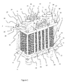
Fig. 1 is a perspective view of a plate heat exchanger assembly according to one embodiment of the invention. -
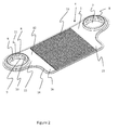
Fig. 2 is a schematic perspective view of the lower plate forming a part of a heat exchanging panel to be used in the assembly. -
Fig. 3 is a schematic perspective view disclosing a plurality of heat exchanger panels arranged one on top of the other with intermediate thermoelectric devices. -
Fig. 4 is a highly schematic view disclosing an alternative position of the compression means. - With reference to
Fig. 1 a plateheat exchanger assembly 1 according to one embodiment of the invention is illustrated. The plateheat exchanger assembly 1 comprises in general aplate package 2 arranged in aframe 3. Theplate package 2 which as such is well known in the art comprises a plurality ofheat exchanging panels 4 which are alternately stacked one on top of the other. - Now turning to
Fig. 2 one example of an individualheat exchanging panel 4 will be discussed. Theheat exchanging panel 4 comprises a first and asecond plate 5 arranged one on top of the other. For illustrative purposes, only thelower plate 5 is disclosed. The non disclosed upper plate has the same mirrored design. - The lower and
upper plates 5 are typically formed by thin pressed metal sheet and have a throughinlet opening 6 and a throughoutlet opening 7. In the disclosed embodiment, the inlet andoutlet openings fluid distributor 8 is arranged in the inlet andoutlet openings fluid distributor 8 has the form of aring 9 provided with acircumferential wall portion 10. Thecircumferential wall portion 10 is provided with a plurality of through distributingholes 11. Thefluid distributors 8 are arranged to distribute fluid across theplate 5. Thefluid distributors 8 serve yet another purpose in that they provide an axial reinforcement of theheat exchanging panel 4 around the inlet andoutlet openings - In the disclosed embodiment the
plate 5 has an essentially flatmajor surface 12 extending between the inlet andoutlet openings - A
turbulator 13 is arranged on the essentially flatmajor surface 12. In the disclosed embodiment theturbulator 13 is formed as a waffled sheet metal structure forming longitudinal channels extending along the longitudinal extension of the lower plate in a direction from theinlet opening 6 to theoutlet opening 7. It goes without saying that the design of theturbulator 13 may be different with remained function. - The
plate 5 is provided with acircumferential ridge 14 forming a supporting contact surface against the upper non-disclosed upper plate to be mounted thereon. - In order of forming an individual
heat exchanging panel 4, alower plate 5 of the type disclosed above is provided with thefluid distributor 8 in the inlet andoutlet openings lower plates 5, together with thefluid distributors 8 and theturbulator 13 are joined by welding, brazing or bonding, thereby forming an integrally joinedheat exchanging panel 4 with two essentially flat opposing major surfaces delimiting an essentially flat flow channel there between extending from theinlet opening 6, via the throughopenings 11 in the circumferential wall portion of thedistributor 8, across the major surface of the panel via the turbulator towards the through holes of thedistributor 8 of theoutlet opening 7 where it will be free to exit theheat exchanging panel 4. - The
heat exchanging panel 4 may imaginary be divided into twofluid supply areas 15 and aheat transfer area 16. Thefluid supply areas 15 extend across and around the inlet andoutlet openings heat transfer area 16 extends there between. It goes without saying that there is no distinct boundaries for the two areas and that their surface extensions depend on the overall design of thepanel 4. Thus, thefluid supply areas 15 and theheat transfer area 16 may be regarded as imaginary areas. In the disclosed embodiment theheat transfer area 16 will be formed by the essentially rectangular flatmajor surface 12 extending between the two lobe shaped inlet and outlet portions which thereby will define twofluid supply areas 15 on opposite sides of theheat transfer area 16. - Now turning to
Fig. 1 and3 , in order of forming aplate package 2 intended for two fluids, two sets ofheat exchanging panels 4 are required, which panels as such may be identical. The first set of panels are arranged for a first fluid whereas the second set of panels are arranged for a second fluid.Panels 4 from the two sets are alternately stacked one on top of the other in a manner that theinlet openings 6 and theoutlet openings 7 ofpanels 4 of the first set are aligned, and that theinlet openings 6 and theoutlet openings 7 ofpanels 4 of the second set are aligned, thereby forming two through inlet channels A, B and two outlet channels C, D along the height of theplate package 2. Thereby a through inlet channel A and a through outlet channel C for a first fluid and a through inlet channel B and a through outlet channel C for a second fluid will be formed. Said channels A, B, C, D are in communication with the respective flat flow channels delimited between two adjacent joinedplates 5 making up the individualheat exchanging panels 4. Sealings (not disclosed) are preferably arranged between thepanels 4 at least around the inlet andoutlet openings - In the thus resulting stacked
plate package 2 two fluid systems will be provided - a first fluid system allowing a first fluid to flow from the first inlet channel A, through all panels in the first set of heat exchanging panels and out via the first outlet channel C, and a second fluid system allowing a second fluid to flow from the second inlet channel B, through all panels in the second set of heat exchanging panels and out via the second outlet channel D. - Now turning to
Fig. 3 at least one thermoelectric device 17 is arranged between two adjacentheat exchanging panels 4 and in thermal contact with theheat transfer area 16 of one heat exchanging panel from each of the first and second sets of heat exchanging panels. In the disclosed embodiment nine thermoelectric devices 17 are arranged between each set ofpanels 4. It goes without saying that the number and pattern may vary. In the disclosed embodiment, the thermoelectric devices 17 are provided withwires 18 extending outside the plate package. To facilitate the illustration, only a some of the thermoelectric devices 17 are provided withwires 18. The characteristics of the thermoelectric devices 17 may be the same throughout theplate package 2, or differ as seen from a position adjacent thefluid supply area 15 comprising theinlet opening 6 to a position adjacent thefluid supply area 15 comprising theoutlet opening 7. - In order of improving thermal transfer from the
heat exchanging panels 4 to the thermoelectric devices 17 and thereby ensuring a high efficiency of the latter aninsulation 19 may be arranged between theheat exchanging panels 4. Theinsulation 19 comprises throughholes 50 receiving the thermoelectric devices 17 whereby the thermoelectric devices 17 will be in direct contact with theheat exchanging panels 4. Thereby the insulation will restrict heat transfer between theheat exchanging panels 4 while at the same time making sure that the heat instead will transfer between thepanels 4 via the thermoelectric devices generating electrical power. Theinsulation 19 may by way of example be a fibrous material, a plastic material or a composite material. - Now turning anew to
Fig.1 , theplate package 2 is arranged in aframe 3. Theframe 3 comprises afirst end portion 20 andsecond end portion 21 arranged on opposite sides of theplate package 2. Eachend portion second sections first sections 22 are arranged across thefluid supply areas 15 of theplate package 2 and thesecond end sections 23 are arranged across theheat transfer areas 16 of theheat exchanging panels 4. - To facilitate fluid supply to the
plate package 4, the inlet and outlet openings of thepanels 4 may be provided withconnection pipes 24 extending through thefirst sections 22. - The first and
second sections second end portions gap 25. Thus there is no metallic contact there between. Accordingly, the first andsecond sections plate package 2. Further, bysuch gap 25 no direct heat transfer and thereby heat losses will take place between the first andsecond sections gap 25 may be provided with an insulation (not disclosed) to further limit heat transfer there between. Accordingly heat losses from theheat transfer area 16 to thefluid supply area 15 may be reduced. Instead the heat transfer will take place from theheat exchanging panels 4 to the thermoelectric devices 17 to thereby improve the efficiency of the thermoelectric devices 17. Further, it is preferred that there is aradial gap 26 between thefirst sections 22 and the connectingpipes 24 of theplate package 2. Suchradial gap 26 contributes to prevention of heat losses in thefluid supply area 15. - A first set of tensioning means 27 extend between the opposing
first sections 22 of the first andsecond end portions holes 29 in thefirst sections 22. The tensioning means are provided with locking means 30 in the form of washers and nuts. The locking means 30 are tensioned with a locking force which is sufficient to provide a leak proof compression of thefluid supply areas 15 of theplate package 2 during operation. Although not disclosed it may be possible to provide the first set of tensioning means with elastic compression means. - A second set of tensioning means 28 extend between the opposing
second sections 23 of the first andsecond end portions 21. In the disclosed embodiment the second set of tensioning means 28 are arranged as tension bars extending via through holes in thesecond sections 23. The second tensioning means 28 are provided with locking means 31 in the form of washers and nuts. Further elastic compression means 32 are arranged between the locking means 31 and thesecond section 23 of the uppersecond end portion 21. Also although not disclosed, the second section of the opposite lower end portion may be provided with corresponding elastic compression means. The elastic compression means 32 may by way of example be helical springs. - The locking means 31 of the
second section 23 are tensioned with a locking force which is sufficient to provide the dimensioned contact pressure between theheat exchanging panels 4 and the thermoelectric devices 17. Any thermal movement during operation across theheat transfer area 16 may be accommodated by the elastic compression means 32. Thereby a more or less constant contact pressure between the thermoelectric devices 17 and theheat exchanging panels 4 may be provided during operation. -
Fig. 4 discloses highly schematically an alternative embodiment of thesecond section 23 wherein the elastic compression means 32 are received in arecess 33 in thesecond section 23 which recess is facing the highly schematically disclosedplate package 4. - The heat exchanger assembly according to the present invention may be used to generate electric power from the exhaust gases of a combustion agent. The first set of heat exchanging panels may be connected to the cooler system circulating refrigerant such as cooler water there through, and the second set of heat exchanging panels may be connected to the outlet of hot exhaust gas generated by the combustion engine. The exhaust gas flow may be re-circulated exhaust gas in an EGR-system used for reduction of nitrogen oxide emissions. Trials have shown that it may be possible to generate 0.5kW while reducing the temperature of the re-circulating exhaust gas from about 650 °C to 250 °C.
- From the description above follows that, although various embodiments of the invention have been described and shown, the invention is not restricted thereto, but may also be embodied in other ways within the scope of the subject-matter defined in the following claims.
Claims (12)
- A plate heat exchanger assembly (1) comprising:a plate package (2) comprising a first and second set of heat exchanging panels (4), each comprising a fluid supply area (15) and a heat transfer area (16), the panels (4) being alternately stacked one on top of the other, and wherein at least one thermoelectric device (17) is arranged between two adjacent heat exchanging panels (4) and in thermal contact with the heat transfer area (16) of one heat exchanging panel from each of the first and second set of heat exchanging panels; anda frame (3) comprising a first end portion (20) and a second end portion (21), each end portion comprising a first section (22) and a second section (23) and the first and second end portions (20, 21) being arranged on opposite sides of the plate package (2), the first end sections (22) being arranged for compression across the fluid supply areas (15) of the heat exchanging panels (4) and the second end sections (23) being arranged for compression across the heat transfer areas (16) of the heat exchanging panels (4),and a first set of tensioning means (27) extending between the first sections (22) of the first and second end portions (20, 21) and a second set of tensioning means (28) extending between the second sections (23) of the first and second end portions (21),the first and second sections (22, 23) of the first and second end portions (20, 21) respectively being mutually movable.
- A plate heat exchanger assembly according to claim 1, wherein the second set of tensioning means (28) comprises elastic compression means (32).
- A plate heat exchanger assembly according to any of the preceding claims, wherein the second set of tensioning means (28) is provided as tension bars, each tension bar being provided with an elastic compression means (32).
- A plate heat exchanger assembly according to any of claims 2-3, wherein the elastic compression means (32) are integrated in the second sections (23) of the second end portions (21).
- The plate heat exchanger assembly according to any of the preceding claims, wherein there is no metallic contact between the first and the second sections (22, 23) of the first and second end portions (20, 21) of the frame (3).
- The plate heat exchanger assembly according to any of the preceding claims, wherein the heat exchanging panels (4) each comprises a first and a second plate (5) arranged one on top of the other and mutually joined to define a flow channel there between, said flow channel being provided with a turbulator (13) extending at least partly across the heat transfer area (16) of the heat exchanging panel (4).
- The plate heat exchanger assembly according to claim 6, wherein the first and second plates (5) and the turbulator (13) together form an integrally joined structure.
- The plate heat exchanger assembly according to any of the preceding claims, wherein the fluid supply area (15) comprises a fluid inlet opening (6) and a fluid outlet opening (7) arranged on opposite sides of the heat transfer area (16).
- A plate heat exchanger assembly according to any of the preceding claims, wherein an insulation(19) is arranged between the heat exchanging panels (4) of the plate package (2), said insulation (19) comprising a through opening (40) receiving the at least one thermoelectric device (17).
- A plate heat exchanger assembly according to any of the preceding claims, wherein the thermoelectric devices (17) are thermoelectric generators.
- A frame (3) for a plate heat exchanger in the form of a plate package (2) comprising a set of first and second heat exchanging panels (4), each panel comprising a fluid supply area (15) and a heat transfer area (16), wherein at least one thermoelectric device (17) is arranged between two adjacent heat exchanging panels (4), wherein the frame (3) comprises a first end portion (20) and a second end portion (21), each end portion comprising a first section (22) and a second section (23), the first and second end portions (20, 21) being arranged on opposite sides of the plate package (2), the first sections being arranged for compression across the fluid supply areas (15) of the heat exchanging panels (4) and the second sections (23) being arranged for compression across the heat transfer areas (16) of the heat exchanging panels (4), and the frame (3) further comprising a first set of tensioning means (27) extending between the first sections (22) of the first and second end portions (20, 21) and a second set of tensioning means (28) extending between the second sections (23) of the first and second end portions (20, 21), wherein the first and second sections (22, 23) of the first and second end portions (20, 21) are respectively mutually movable.
- Use of a plate heat exchanger assembly according to any of claims 1-10, in a combustion engine for extracting electric power from exhaust gases.
Priority Applications (1)
| Application Number | Priority Date | Filing Date | Title |
|---|---|---|---|
| EP14173789.0A EP2960953B1 (en) | 2014-06-25 | 2014-06-25 | Plate heat exchanger assembly and a frame to be used in such assembly |
Applications Claiming Priority (1)
| Application Number | Priority Date | Filing Date | Title |
|---|---|---|---|
| EP14173789.0A EP2960953B1 (en) | 2014-06-25 | 2014-06-25 | Plate heat exchanger assembly and a frame to be used in such assembly |
Publications (2)
| Publication Number | Publication Date |
|---|---|
| EP2960953A1 true EP2960953A1 (en) | 2015-12-30 |
| EP2960953B1 EP2960953B1 (en) | 2018-04-11 |
Family
ID=50980966
Family Applications (1)
| Application Number | Title | Priority Date | Filing Date |
|---|---|---|---|
| EP14173789.0A Active EP2960953B1 (en) | 2014-06-25 | 2014-06-25 | Plate heat exchanger assembly and a frame to be used in such assembly |
Country Status (1)
| Country | Link |
|---|---|
| EP (1) | EP2960953B1 (en) |
Cited By (3)
| Publication number | Priority date | Publication date | Assignee | Title |
|---|---|---|---|---|
| DE102016217894A1 (en) * | 2016-09-19 | 2018-03-22 | Mahle International Gmbh | Thermoelectric generator, in particular for a motor vehicle |
| US20180080363A1 (en) * | 2016-09-19 | 2018-03-22 | Mahle International Gmbh | Thermoelectric generator, in particular for a motor vehicle |
| US20210091292A1 (en) * | 2018-06-20 | 2021-03-25 | Kohler Mira Limited | Energy recovery |
Citations (8)
| Publication number | Priority date | Publication date | Assignee | Title |
|---|---|---|---|---|
| EP0450822A1 (en) * | 1990-03-30 | 1991-10-09 | United Dominion Industries, Inc. | Heat exchanger plate apparatus |
| FR2702829A1 (en) * | 1993-02-04 | 1994-09-23 | France Etat Armement | Thermoelectric installation |
| US5584183A (en) * | 1994-02-18 | 1996-12-17 | Solid State Cooling Systems | Thermoelectric heat exchanger |
| JPH11340520A (en) * | 1998-05-22 | 1999-12-10 | Ube Ind Ltd | Heat exchanger using thermoelectric conversion module |
| US20040206386A1 (en) * | 2003-04-17 | 2004-10-21 | Watts Phillip C. | Same plane multiple thermoelectric mounting system |
| US20050194034A1 (en) * | 2004-03-04 | 2005-09-08 | Hiroo Yamaguchi | Thermoelectric generator |
| DE102007063196A1 (en) * | 2007-12-19 | 2009-07-02 | Bayerische Motoren Werke Aktiengesellschaft | Thermoelectric generator, has connecting device comprising strapping element that sectionally encloses stack axis, where compressive force exerts on stack axis and is approximately aligned parallel to stack axis |
| US20130213449A1 (en) | 2012-02-20 | 2013-08-22 | Marlow Industries, Inc. | Thermoelectric plate and frame exchanger |
-
2014
- 2014-06-25 EP EP14173789.0A patent/EP2960953B1/en active Active
Patent Citations (8)
| Publication number | Priority date | Publication date | Assignee | Title |
|---|---|---|---|---|
| EP0450822A1 (en) * | 1990-03-30 | 1991-10-09 | United Dominion Industries, Inc. | Heat exchanger plate apparatus |
| FR2702829A1 (en) * | 1993-02-04 | 1994-09-23 | France Etat Armement | Thermoelectric installation |
| US5584183A (en) * | 1994-02-18 | 1996-12-17 | Solid State Cooling Systems | Thermoelectric heat exchanger |
| JPH11340520A (en) * | 1998-05-22 | 1999-12-10 | Ube Ind Ltd | Heat exchanger using thermoelectric conversion module |
| US20040206386A1 (en) * | 2003-04-17 | 2004-10-21 | Watts Phillip C. | Same plane multiple thermoelectric mounting system |
| US20050194034A1 (en) * | 2004-03-04 | 2005-09-08 | Hiroo Yamaguchi | Thermoelectric generator |
| DE102007063196A1 (en) * | 2007-12-19 | 2009-07-02 | Bayerische Motoren Werke Aktiengesellschaft | Thermoelectric generator, has connecting device comprising strapping element that sectionally encloses stack axis, where compressive force exerts on stack axis and is approximately aligned parallel to stack axis |
| US20130213449A1 (en) | 2012-02-20 | 2013-08-22 | Marlow Industries, Inc. | Thermoelectric plate and frame exchanger |
Cited By (4)
| Publication number | Priority date | Publication date | Assignee | Title |
|---|---|---|---|---|
| DE102016217894A1 (en) * | 2016-09-19 | 2018-03-22 | Mahle International Gmbh | Thermoelectric generator, in particular for a motor vehicle |
| US20180080363A1 (en) * | 2016-09-19 | 2018-03-22 | Mahle International Gmbh | Thermoelectric generator, in particular for a motor vehicle |
| US10374138B2 (en) | 2016-09-19 | 2019-08-06 | Mahle International Gmbh | Thermoelectric generator, in particular for a motor vehicle |
| US20210091292A1 (en) * | 2018-06-20 | 2021-03-25 | Kohler Mira Limited | Energy recovery |
Also Published As
| Publication number | Publication date |
|---|---|
| EP2960953B1 (en) | 2018-04-11 |
Similar Documents
| Publication | Publication Date | Title |
|---|---|---|
| US8826663B2 (en) | Heat exchanger | |
| US9466778B2 (en) | Thermoelectric generator unit | |
| US20160003553A1 (en) | Heat transfer device | |
| US10215496B2 (en) | Multi-flow heat exchanger for exchanging heat between cool fluid and hot fluid | |
| US9748465B2 (en) | Thermoelectric module, heat exchanger, exhaust system and internal combustion engine | |
| EP2960953B1 (en) | Plate heat exchanger assembly and a frame to be used in such assembly | |
| US20180149061A1 (en) | Thermoelectric Generator for Converting Heat of a Hot Gas Flow Into Electric Energy | |
| US20130309798A1 (en) | Method For Manufacturing A Thermoelectric Device, Especially Intended To Generate An Electrical Current In An Automotive Vehicle | |
| WO2010102397A1 (en) | Heat exchanger with cast housing and method of making same | |
| US10024604B2 (en) | Stacked plate heat exchanger | |
| US9416712B2 (en) | Thermoelectric module with heat exchanger | |
| US10193048B2 (en) | Energy recovering assembly and a method of providing the same | |
| KR101988992B1 (en) | heat exchanger for cooling electric element | |
| EP3404227B1 (en) | Thermoelectric generator for an exhaust system of an internal combustion engine | |
| EP2587207B1 (en) | Power system | |
| US11024787B2 (en) | Thermoelectric power generation device | |
| WO2017212822A1 (en) | Thermoelectric generator | |
| CN111141163B (en) | Welded plate heat exchanger | |
| JP2011208814A (en) | Water-cooling jacket | |
| CN116601450A (en) | Tube for heat exchanger | |
| JP2013130359A (en) | Duct for heat exchanger |
Legal Events
| Date | Code | Title | Description |
|---|---|---|---|
| PUAI | Public reference made under article 153(3) epc to a published international application that has entered the european phase |
Free format text: ORIGINAL CODE: 0009012 |
|
| 17P | Request for examination filed |
Effective date: 20140625 |
|
| AK | Designated contracting states |
Kind code of ref document: A1 Designated state(s): AL AT BE BG CH CY CZ DE DK EE ES FI FR GB GR HR HU IE IS IT LI LT LU LV MC MK MT NL NO PL PT RO RS SE SI SK SM TR |
|
| AX | Request for extension of the european patent |
Extension state: BA ME |
|
| GRAP | Despatch of communication of intention to grant a patent |
Free format text: ORIGINAL CODE: EPIDOSNIGR1 |
|
| STAA | Information on the status of an ep patent application or granted ep patent |
Free format text: STATUS: GRANT OF PATENT IS INTENDED |
|
| RIC1 | Information provided on ipc code assigned before grant |
Ipc: F28F 3/08 20060101ALI20171101BHEP Ipc: H01L 35/30 20060101AFI20171101BHEP Ipc: F28D 9/00 20060101ALI20171101BHEP Ipc: F28D 7/00 20060101ALI20171101BHEP |
|
| INTG | Intention to grant announced |
Effective date: 20171205 |
|
| GRAS | Grant fee paid |
Free format text: ORIGINAL CODE: EPIDOSNIGR3 |
|
| GRAA | (expected) grant |
Free format text: ORIGINAL CODE: 0009210 |
|
| STAA | Information on the status of an ep patent application or granted ep patent |
Free format text: STATUS: THE PATENT HAS BEEN GRANTED |
|
| AK | Designated contracting states |
Kind code of ref document: B1 Designated state(s): AL AT BE BG CH CY CZ DE DK EE ES FI FR GB GR HR HU IE IS IT LI LT LU LV MC MK MT NL NO PL PT RO RS SE SI SK SM TR |
|
| REG | Reference to a national code |
Ref country code: GB Ref legal event code: FG4D |
|
| RIN1 | Information on inventor provided before grant (corrected) |
Inventor name: STROEMER, FREDRIK Inventor name: ANDREASSON, FREDRIK Inventor name: ROSS, MARTIN |
|
| REG | Reference to a national code |
Ref country code: CH Ref legal event code: EP |
|
| REG | Reference to a national code |
Ref country code: AT Ref legal event code: REF Ref document number: 988897 Country of ref document: AT Kind code of ref document: T Effective date: 20180415 |
|
| REG | Reference to a national code |
Ref country code: IE Ref legal event code: FG4D |
|
| REG | Reference to a national code |
Ref country code: DE Ref legal event code: R096 Ref document number: 602014023595 Country of ref document: DE |
|
| REG | Reference to a national code |
Ref country code: SE Ref legal event code: TRGR |
|
| REG | Reference to a national code |
Ref country code: NL Ref legal event code: MP Effective date: 20180411 |
|
| REG | Reference to a national code |
Ref country code: LT Ref legal event code: MG4D |
|
| PG25 | Lapsed in a contracting state [announced via postgrant information from national office to epo] |
Ref country code: NL Free format text: LAPSE BECAUSE OF FAILURE TO SUBMIT A TRANSLATION OF THE DESCRIPTION OR TO PAY THE FEE WITHIN THE PRESCRIBED TIME-LIMIT Effective date: 20180411 |
|
| PG25 | Lapsed in a contracting state [announced via postgrant information from national office to epo] |
Ref country code: LT Free format text: LAPSE BECAUSE OF FAILURE TO SUBMIT A TRANSLATION OF THE DESCRIPTION OR TO PAY THE FEE WITHIN THE PRESCRIBED TIME-LIMIT Effective date: 20180411 Ref country code: BG Free format text: LAPSE BECAUSE OF FAILURE TO SUBMIT A TRANSLATION OF THE DESCRIPTION OR TO PAY THE FEE WITHIN THE PRESCRIBED TIME-LIMIT Effective date: 20180711 Ref country code: FI Free format text: LAPSE BECAUSE OF FAILURE TO SUBMIT A TRANSLATION OF THE DESCRIPTION OR TO PAY THE FEE WITHIN THE PRESCRIBED TIME-LIMIT Effective date: 20180411 Ref country code: AL Free format text: LAPSE BECAUSE OF FAILURE TO SUBMIT A TRANSLATION OF THE DESCRIPTION OR TO PAY THE FEE WITHIN THE PRESCRIBED TIME-LIMIT Effective date: 20180411 Ref country code: ES Free format text: LAPSE BECAUSE OF FAILURE TO SUBMIT A TRANSLATION OF THE DESCRIPTION OR TO PAY THE FEE WITHIN THE PRESCRIBED TIME-LIMIT Effective date: 20180411 Ref country code: NO Free format text: LAPSE BECAUSE OF FAILURE TO SUBMIT A TRANSLATION OF THE DESCRIPTION OR TO PAY THE FEE WITHIN THE PRESCRIBED TIME-LIMIT Effective date: 20180711 Ref country code: PL Free format text: LAPSE BECAUSE OF FAILURE TO SUBMIT A TRANSLATION OF THE DESCRIPTION OR TO PAY THE FEE WITHIN THE PRESCRIBED TIME-LIMIT Effective date: 20180411 |
|
| PG25 | Lapsed in a contracting state [announced via postgrant information from national office to epo] |
Ref country code: LV Free format text: LAPSE BECAUSE OF FAILURE TO SUBMIT A TRANSLATION OF THE DESCRIPTION OR TO PAY THE FEE WITHIN THE PRESCRIBED TIME-LIMIT Effective date: 20180411 Ref country code: GR Free format text: LAPSE BECAUSE OF FAILURE TO SUBMIT A TRANSLATION OF THE DESCRIPTION OR TO PAY THE FEE WITHIN THE PRESCRIBED TIME-LIMIT Effective date: 20180712 Ref country code: HR Free format text: LAPSE BECAUSE OF FAILURE TO SUBMIT A TRANSLATION OF THE DESCRIPTION OR TO PAY THE FEE WITHIN THE PRESCRIBED TIME-LIMIT Effective date: 20180411 Ref country code: RS Free format text: LAPSE BECAUSE OF FAILURE TO SUBMIT A TRANSLATION OF THE DESCRIPTION OR TO PAY THE FEE WITHIN THE PRESCRIBED TIME-LIMIT Effective date: 20180411 |
|
| REG | Reference to a national code |
Ref country code: AT Ref legal event code: MK05 Ref document number: 988897 Country of ref document: AT Kind code of ref document: T Effective date: 20180411 |
|
| PG25 | Lapsed in a contracting state [announced via postgrant information from national office to epo] |
Ref country code: PT Free format text: LAPSE BECAUSE OF FAILURE TO SUBMIT A TRANSLATION OF THE DESCRIPTION OR TO PAY THE FEE WITHIN THE PRESCRIBED TIME-LIMIT Effective date: 20180813 |
|
| REG | Reference to a national code |
Ref country code: DE Ref legal event code: R097 Ref document number: 602014023595 Country of ref document: DE |
|
| PG25 | Lapsed in a contracting state [announced via postgrant information from national office to epo] |
Ref country code: CZ Free format text: LAPSE BECAUSE OF FAILURE TO SUBMIT A TRANSLATION OF THE DESCRIPTION OR TO PAY THE FEE WITHIN THE PRESCRIBED TIME-LIMIT Effective date: 20180411 Ref country code: RO Free format text: LAPSE BECAUSE OF FAILURE TO SUBMIT A TRANSLATION OF THE DESCRIPTION OR TO PAY THE FEE WITHIN THE PRESCRIBED TIME-LIMIT Effective date: 20180411 Ref country code: EE Free format text: LAPSE BECAUSE OF FAILURE TO SUBMIT A TRANSLATION OF THE DESCRIPTION OR TO PAY THE FEE WITHIN THE PRESCRIBED TIME-LIMIT Effective date: 20180411 Ref country code: SK Free format text: LAPSE BECAUSE OF FAILURE TO SUBMIT A TRANSLATION OF THE DESCRIPTION OR TO PAY THE FEE WITHIN THE PRESCRIBED TIME-LIMIT Effective date: 20180411 Ref country code: DK Free format text: LAPSE BECAUSE OF FAILURE TO SUBMIT A TRANSLATION OF THE DESCRIPTION OR TO PAY THE FEE WITHIN THE PRESCRIBED TIME-LIMIT Effective date: 20180411 Ref country code: AT Free format text: LAPSE BECAUSE OF FAILURE TO SUBMIT A TRANSLATION OF THE DESCRIPTION OR TO PAY THE FEE WITHIN THE PRESCRIBED TIME-LIMIT Effective date: 20180411 |
|
| REG | Reference to a national code |
Ref country code: CH Ref legal event code: PL |
|
| PLBE | No opposition filed within time limit |
Free format text: ORIGINAL CODE: 0009261 |
|
| STAA | Information on the status of an ep patent application or granted ep patent |
Free format text: STATUS: NO OPPOSITION FILED WITHIN TIME LIMIT |
|
| PG25 | Lapsed in a contracting state [announced via postgrant information from national office to epo] |
Ref country code: SM Free format text: LAPSE BECAUSE OF FAILURE TO SUBMIT A TRANSLATION OF THE DESCRIPTION OR TO PAY THE FEE WITHIN THE PRESCRIBED TIME-LIMIT Effective date: 20180411 Ref country code: IT Free format text: LAPSE BECAUSE OF FAILURE TO SUBMIT A TRANSLATION OF THE DESCRIPTION OR TO PAY THE FEE WITHIN THE PRESCRIBED TIME-LIMIT Effective date: 20180411 |
|
| REG | Reference to a national code |
Ref country code: BE Ref legal event code: MM Effective date: 20180630 |
|
| 26N | No opposition filed |
Effective date: 20190114 |
|
| REG | Reference to a national code |
Ref country code: IE Ref legal event code: MM4A |
|
| GBPC | Gb: european patent ceased through non-payment of renewal fee |
Effective date: 20180711 |
|
| PG25 | Lapsed in a contracting state [announced via postgrant information from national office to epo] |
Ref country code: LU Free format text: LAPSE BECAUSE OF NON-PAYMENT OF DUE FEES Effective date: 20180625 Ref country code: MC Free format text: LAPSE BECAUSE OF FAILURE TO SUBMIT A TRANSLATION OF THE DESCRIPTION OR TO PAY THE FEE WITHIN THE PRESCRIBED TIME-LIMIT Effective date: 20180411 |
|
| PG25 | Lapsed in a contracting state [announced via postgrant information from national office to epo] |
Ref country code: IE Free format text: LAPSE BECAUSE OF NON-PAYMENT OF DUE FEES Effective date: 20180625 Ref country code: CH Free format text: LAPSE BECAUSE OF NON-PAYMENT OF DUE FEES Effective date: 20180630 Ref country code: FR Free format text: LAPSE BECAUSE OF NON-PAYMENT OF DUE FEES Effective date: 20180630 Ref country code: LI Free format text: LAPSE BECAUSE OF NON-PAYMENT OF DUE FEES Effective date: 20180630 Ref country code: GB Free format text: LAPSE BECAUSE OF NON-PAYMENT OF DUE FEES Effective date: 20180711 |
|
| PG25 | Lapsed in a contracting state [announced via postgrant information from national office to epo] |
Ref country code: BE Free format text: LAPSE BECAUSE OF NON-PAYMENT OF DUE FEES Effective date: 20180630 Ref country code: SI Free format text: LAPSE BECAUSE OF FAILURE TO SUBMIT A TRANSLATION OF THE DESCRIPTION OR TO PAY THE FEE WITHIN THE PRESCRIBED TIME-LIMIT Effective date: 20180411 |
|
| PG25 | Lapsed in a contracting state [announced via postgrant information from national office to epo] |
Ref country code: MT Free format text: LAPSE BECAUSE OF NON-PAYMENT OF DUE FEES Effective date: 20180625 |
|
| PG25 | Lapsed in a contracting state [announced via postgrant information from national office to epo] |
Ref country code: TR Free format text: LAPSE BECAUSE OF FAILURE TO SUBMIT A TRANSLATION OF THE DESCRIPTION OR TO PAY THE FEE WITHIN THE PRESCRIBED TIME-LIMIT Effective date: 20180411 |
|
| PG25 | Lapsed in a contracting state [announced via postgrant information from national office to epo] |
Ref country code: CY Free format text: LAPSE BECAUSE OF FAILURE TO SUBMIT A TRANSLATION OF THE DESCRIPTION OR TO PAY THE FEE WITHIN THE PRESCRIBED TIME-LIMIT Effective date: 20180411 Ref country code: MK Free format text: LAPSE BECAUSE OF NON-PAYMENT OF DUE FEES Effective date: 20180411 Ref country code: HU Free format text: LAPSE BECAUSE OF FAILURE TO SUBMIT A TRANSLATION OF THE DESCRIPTION OR TO PAY THE FEE WITHIN THE PRESCRIBED TIME-LIMIT; INVALID AB INITIO Effective date: 20140625 |
|
| PG25 | Lapsed in a contracting state [announced via postgrant information from national office to epo] |
Ref country code: IS Free format text: LAPSE BECAUSE OF FAILURE TO SUBMIT A TRANSLATION OF THE DESCRIPTION OR TO PAY THE FEE WITHIN THE PRESCRIBED TIME-LIMIT Effective date: 20180811 |
|
| REG | Reference to a national code |
Ref country code: DE Ref legal event code: R079 Ref document number: 602014023595 Country of ref document: DE Free format text: PREVIOUS MAIN CLASS: H01L0035300000 Ipc: H10N0010130000 |
|
| PGFP | Annual fee paid to national office [announced via postgrant information from national office to epo] |
Ref country code: SE Payment date: 20230314 Year of fee payment: 10 |
|
| P01 | Opt-out of the competence of the unified patent court (upc) registered |
Effective date: 20230419 |
|
| PGFP | Annual fee paid to national office [announced via postgrant information from national office to epo] |
Ref country code: DE Payment date: 20230502 Year of fee payment: 10 |