EP2960670A1 - Gas cell with anti-relaxation coating - Google Patents
Gas cell with anti-relaxation coating Download PDFInfo
- Publication number
- EP2960670A1 EP2960670A1 EP15172881.3A EP15172881A EP2960670A1 EP 2960670 A1 EP2960670 A1 EP 2960670A1 EP 15172881 A EP15172881 A EP 15172881A EP 2960670 A1 EP2960670 A1 EP 2960670A1
- Authority
- EP
- European Patent Office
- Prior art keywords
- gas cell
- coating layer
- molecules
- inner walls
- gas
- Prior art date
- Legal status (The legal status is an assumption and is not a legal conclusion. Google has not performed a legal analysis and makes no representation as to the accuracy of the status listed.)
- Withdrawn
Links
Images



Classifications
-
- F—MECHANICAL ENGINEERING; LIGHTING; HEATING; WEAPONS; BLASTING
- F17—STORING OR DISTRIBUTING GASES OR LIQUIDS
- F17C—VESSELS FOR CONTAINING OR STORING COMPRESSED, LIQUEFIED OR SOLIDIFIED GASES; FIXED-CAPACITY GAS-HOLDERS; FILLING VESSELS WITH, OR DISCHARGING FROM VESSELS, COMPRESSED, LIQUEFIED, OR SOLIDIFIED GASES
- F17C13/00—Details of vessels or of the filling or discharging of vessels
-
- G—PHYSICS
- G01—MEASURING; TESTING
- G01R—MEASURING ELECTRIC VARIABLES; MEASURING MAGNETIC VARIABLES
- G01R33/00—Arrangements or instruments for measuring magnetic variables
- G01R33/02—Measuring direction or magnitude of magnetic fields or magnetic flux
- G01R33/032—Measuring direction or magnitude of magnetic fields or magnetic flux using magneto-optic devices, e.g. Faraday or Cotton-Mouton effect
- G01R33/0322—Measuring direction or magnitude of magnetic fields or magnetic flux using magneto-optic devices, e.g. Faraday or Cotton-Mouton effect using the Faraday or Voigt effect
-
- G—PHYSICS
- G01—MEASURING; TESTING
- G01R—MEASURING ELECTRIC VARIABLES; MEASURING MAGNETIC VARIABLES
- G01R33/00—Arrangements or instruments for measuring magnetic variables
- G01R33/20—Arrangements or instruments for measuring magnetic variables involving magnetic resonance
- G01R33/28—Details of apparatus provided for in groups G01R33/44 - G01R33/64
- G01R33/282—Means specially adapted for hyperpolarisation or for hyperpolarised contrast agents, e.g. for the generation of hyperpolarised gases using optical pumping cells, for storing hyperpolarised contrast agents or for the determination of the polarisation of a hyperpolarised contrast agent
-
- G—PHYSICS
- G01—MEASURING; TESTING
- G01N—INVESTIGATING OR ANALYSING MATERIALS BY DETERMINING THEIR CHEMICAL OR PHYSICAL PROPERTIES
- G01N24/00—Investigating or analyzing materials by the use of nuclear magnetic resonance, electron paramagnetic resonance or other spin effects
- G01N24/006—Investigating or analyzing materials by the use of nuclear magnetic resonance, electron paramagnetic resonance or other spin effects using optical pumping
-
- G—PHYSICS
- G01—MEASURING; TESTING
- G01R—MEASURING ELECTRIC VARIABLES; MEASURING MAGNETIC VARIABLES
- G01R33/00—Arrangements or instruments for measuring magnetic variables
- G01R33/20—Arrangements or instruments for measuring magnetic variables involving magnetic resonance
- G01R33/24—Arrangements or instruments for measuring magnetic variables involving magnetic resonance for measuring direction or magnitude of magnetic fields or magnetic flux
- G01R33/26—Arrangements or instruments for measuring magnetic variables involving magnetic resonance for measuring direction or magnitude of magnetic fields or magnetic flux using optical pumping
-
- Y—GENERAL TAGGING OF NEW TECHNOLOGICAL DEVELOPMENTS; GENERAL TAGGING OF CROSS-SECTIONAL TECHNOLOGIES SPANNING OVER SEVERAL SECTIONS OF THE IPC; TECHNICAL SUBJECTS COVERED BY FORMER USPC CROSS-REFERENCE ART COLLECTIONS [XRACs] AND DIGESTS
- Y02—TECHNOLOGIES OR APPLICATIONS FOR MITIGATION OR ADAPTATION AGAINST CLIMATE CHANGE
- Y02E—REDUCTION OF GREENHOUSE GAS [GHG] EMISSIONS, RELATED TO ENERGY GENERATION, TRANSMISSION OR DISTRIBUTION
- Y02E60/00—Enabling technologies; Technologies with a potential or indirect contribution to GHG emissions mitigation
- Y02E60/30—Hydrogen technology
- Y02E60/32—Hydrogen storage
Definitions
- the present invention relates to a gas cell having a coating layer on inner walls.
- Non-patent Document 1 JP-A-2013-7720
- Non-patent Document 1 E. B. Alexandrov and M. V. Balabas, "Light-induced desorption of alkali-metal atoms from paraffin coating", Physical Review A 66, 042903 (2002 )
- Non-patent Document 2 N. Castagna, G. Bison, G.
- Patent Document 1 a preferable structure of a coating layer for preventing relaxation of spin polarization is not mentioned.
- An advantage of some aspects of the invention is to provide a preferable structure of a coating layer for preventing relaxation of spin polarization.
- a gas cell according to an aspect of the invention includes a cell main body having an internal space defined by inner walls, a gas of alkali metal or hydrogen sealed in the internal space, and a coating layer formed at least on part of the inner walls using a material having a long-chain molecule structure, wherein molecules more than half of molecules forming the coating layer are perpendicularly oriented with respect to the inner walls.
- the coating layer includes a two-dimensional crystal film in which the perpendicularly-oriented molecules are periodically and two-dimensionally arranged.
- a plurality of the two-dimensional crystal films are stacked in directions perpendicular to the inner walls.
- one molecule is bonded to the other molecules by other chemical binding than van der Waals binding.
- the coating layer is formed using hydrocarbon having unsaturated bonds.
- Fig. 1 is a block diagram showing a configuration of a magnetometric apparatus 1 according to one embodiment.
- the magnetometric apparatus 1 is a biological state measuring apparatus that measures a magnetic field generated from a living body including a magnetic field generated from a heart (cardiac magnetic field) or a magnetic field generated from a brain (cerebral magnetic field) as an index of the state of the living body.
- the magnetometric apparatus 1 has a gas cell array 10, a pump light irradiation unit 20, a probe light irradiation unit 30, and a detection unit 40.
- the gas cell array 10 has a plurality of gas cells. Within the plurality of gas cells, an alkali metal gas (e.g. cesium (Cs)) is sealed.
- Cs cesium
- the pump light irradiation unit 20 outputs pump light that interacts with alkali metal atoms (e.g. light having a wavelength of 894 nm corresponding to the D1 line of cesium) .
- the pump light has a circularly-polarized light component.
- the outermost electrons of the alkali metal atoms are excited and spin polarization is caused.
- the spin-polarized alkali metal atoms precess due to a magnetic field B generated by a measured object.
- the spin polarization of one alkali metal atom is relaxed with time, however, the pump light is continuous wave (CW) light and formation and relaxation of spin polarization are repeated simultaneously in parallel and continuously. As a result, stationary spin polarization is formed as a whole atom cluster.
- CW continuous wave
- the probe light irradiation unit 30 outputs probe light having a linearly-polarized light component. Before and after transmission through the gas cell, the plane of polarization of the probe light rotates due to the Faraday effect. The rotation angle of the polarization plane is expressed as a function of the magnetic field B.
- the detection unit 40 detects the rotation angle of the probe light.
- the detection unit 40 has a photodetector that outputs a signal in response to an amount of incident light, a processor that processes the signal, and a memory that stores data.
- the processor calculates the magnitude of the magnetic field B using the signal output from the photodetector.
- the processor writes data representing the calculation result in the memory. In this manner, a user may obtain information of the magnetic field B generated by the measured object.
- Fig. 2 is an appearance diagram of the gas cell array 10.
- the gas cell array 10 has a plurality (2 x 2) of gas cells 11 two-dimensionally arranged in a matrix along a first direction and a second direction.
- an xyz orthogonal coordinate system is defined with the first direction as an x-axis positive direction and the second direction as a y-axis positive direction.
- Fig. 3 is a sectional view along III-III of the gas cell 11. This section is in parallel to the yz-plane.
- the main body of the gas cell 11 has light transmissivity and is formed using a material that does not react with the sealed alkali metal and does not transmit the alkali metal atoms, e.g., quartz glass or borosilicate glass.
- the gas cell 11 has a principal chamber 111 and an auxiliary chamber 112 as internal spaces defined by inner walls of the main body.
- the principal chamber 111 is a space for the gas cell 11 to fulfill a function as an sensing device, i.e., a space in which the alkali metal gas is sealed.
- the auxiliary chamber 112 is a space that functions as an alkali metal reservoir.
- the alkali metal gas sealed in the principal chamber 111 is solidified at a lower temperature.
- the solidified alkali metal attaches to the wall surface of the principal chamber 111, the pump light or probe light is hindered and problems are caused in the measurement.
- the alkali metal reservoir is a space in which the alkali metal is held for preventing the problems in the measurement. For example, a temperature difference is made between the principal chamber 111 and the auxiliary chamber 112, and thereby, the alkali metal is controlled to stay in the auxiliary chamber 112.
- the principal chamber 111 and the auxiliary chamber 112 are connected by a vent hole 113.
- the diameter of the vent hole 113 is smaller.
- the principal chamber 111 has a rectangular parallelepiped shape (except the vent hole 113 and the auxiliary chamber 112, the gas cell 11 has a rectangular parallelepiped shape).
- the gas cell 11 has a coating layer 114 at least on part of the wall surfaces of the principal chamber 111.
- the coating layer 114 is provided for preventing relaxation of spin polarization.
- the coating layer 114 is formed using hydrocarbon having a straight-chain molecule structure, e.g., paraffin.
- the paraffin refers to alkane having a carbon number of 20 or more (chain saturated hydrocarbon having a general formula of C n H 2n+2 ). It is preferable that the molecular structure of paraffin has a straight chain without branching. Further, the carbon number is preferably from 40 to 60 and more preferably about 50.
- Fig. 4 is a schematic diagram showing a structure of the coating layer 114.
- paraffin having a straight-chain molecular structure is used as the material of the coating layer 114.
- the states assumed by paraffin molecules include a perpendicular orientation and a parallel orientation.
- the perpendicular orientation refers to an orientation of paraffin molecules perpendicular to the surface (the inner wall surface of the principal chamber 111) and the parallel orientation refers to an orientation of paraffin molecules in parallel to the surface.
- the terms of "perpendicular” and “parallel” do not only mean mathematically and strictly perpendicular and parallel but also include states with shifts from strictly perpendicular and parallel in a predetermined amount or less.
- the coating layer 114 is not necessarily an ideal single-crystal film.
- vacuum deposition e.g. vacuum deposition is used.
- a plurality of crystal nuclei are generated on the surface, and then, crystal grains grow from the crystal nuclei as bases.
- the paraffin film formed by vacuum deposition is a polycrystalline film.
- the crystal grain boundary is largely lattice-mismatched, and weak electric or magnetic polarization is generated in the paraffin molecules due to lattice mismatch.
- the polarization increases the surface free energy and increases the absorption time of the colliding atoms. That is, the polarization adversely affects the relaxation action for spin polarization.
- the orientation of paraffin molecules will be considered.
- the molecules in the perpendicular orientation and the molecules in the parallel orientation are mixed.
- the lattice mismatch at the crystal grain boundary between the crystal grains in the perpendicular orientation and the crystal grains in the parallel orientation may be larger than that of the crystal grain boundary between the crystal grains in two horizontal orientations with different crystal axes, and it is considered that the reduction of the relaxation action for spin polarization is larger.
- the coating layer 114 has the smaller crystal grain boundary between the crystal grains in the perpendicular orientation and the crystal grains in the parallel orientation. Accordingly, in the coating layer 114, the paraffin molecules are perpendicularly oriented over the nearly entire surface.
- the coating layer 114 is a single molecular layer formed by single paraffin molecules in the perpendicular direction, i.e., a two-dimensional crystal film.
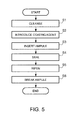
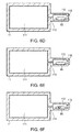
- Fig. 5 is a flowchart showing a method of manufacturing the gas cell 11. Further, Figs. 6A to 6F show states of the gas cell at respective steps. Here, the explanation is started from the state in which the principal chamber 111 and the vent hole 113 are formed ( Fig. 6A ). At the time, the auxiliary chamber 112 is not completely formed and open to the outside air via an opening 115.
- the gas cell 11 is cleansed.
- cleansing e. g. at least one of cleansing using an acid solution or heating in a reduced-pressure atmosphere is used.
- a coating agent for formation of the coating layer 114 is introduced into the principal chamber 111.
- the coating agent is introduced via a needle plug 92 inserted into the opening 115 ( Fig. 6B ) in a reduced-pressure atmosphere.
- the auxiliary chamber 112 is heated by a heater 91.
- the auxiliary chamber 112 is heated, and thereby, the coating agent is absorbed and deposited on the inner walls of the principal chamber 111, not the auxiliary chamber 112.
- an ampule 93 is introduced into the auxiliary chamber 112 ( Fig. 6C ). Inside of the ampule 93, alkali metal atoms are encapsulated.
- the auxiliary chamber 112 is sealed ( Fig. 6D ).
- the auxiliary chamber 112 is sealed by closing the opening 115 with a lid 116 in a reduced-pressure atmosphere.
- the lid 116 is e.g. a lid formed using the same material as the gas cell 11.
- the lid 116 and the gas cell 11 are bonded using e.g. low-melting-point glass.
- ripening (homogenization) is performed ( Fig. 6E ).
- the ripening is heating treatment for perpendicular orientation of paraffin molecules to e.g. a temperature immediately below the melting point of paraffin.
- the paraffin molecules are desorbed from the crystal grains and repeatedly perpendicularly oriented, migrated, and recombined.
- a film close to a perpendicularly-oriented single crystal may be obtained.
- the ampule 93 is broken ( Fig. 6F ).
- the ampule 93 is broken, the alkali metal atoms encapsulated inside are diffused and the principal chamber 111 is filled with the alkali metal.
- the ampule 93 is broken by applying e.g. heat by laser radiation or the like or a physical impact thereto.
- steps S5 and S6 may be exchanged. That is, ripening may be performed after the ampule is broken.
- not all of the paraffin molecules are necessarily perpendicularly oriented. For example, it is necessary that more than half of the paraffin molecules are perpendicularly oriented. Note that whether or not more than half of the paraffin molecules are perpendicularly oriented is determined using e.g. an intensity ratio between a diffraction peak corresponding to the perpendicular orientation and a diffraction peak corresponding to the parallel orientation in X-ray diffraction measurement.
- the coating layer 114 is not limited to the single molecule layer.
- the coating layer 114 may have a structure in which two or more molecule layers of paraffin are stacked. With the single molecule layer, if one molecule layer is peeled, the wall surface of the cell is exposed and the relaxation effect for spin polarization is lost. However, with the two or more molecule layers, even when one molecule layer is peeled, paraffin molecules underneath may maintain the relaxation effect for spin polarization. That is, reliability of the coating layer (heat resistance, long-term reliability, etc.) may be improved.
- the material of the coating layer 114 is not limited to those explained in the embodiment.
- the perpendicularly-oriented paraffin molecules are bound to the adjacent molecules by van der Waals force (van der Waals binding).
- van der Waals force reaches a shorter range and is very weak, and thus, problems may occur in heat resistance and long-term reliability of the coating layer.
- a film having a structure in which adjacent molecules chemically bind may be used.
- the chemically binding here refers to other binding than van der Waals binding, e.g. covalent binding or ion binding.
- As a coating agent for formation of the film having the structure e.g.
- hydrocarbon having unsaturated bonds in basic skeletons is used.
- the film is formed using the agent, perpendicularly oriented by ripening, and then, the unsaturated bonds are activated by ultraviolet irradiation or the like, and the basic skeletons are bonded.
- hydrocarbon but also organic polymer such as fluorocarbon or silicone may be used as the material of the coating layer 114.
- the shape of the gas cell 11 is not limited to that explained in the embodiment.
- the outer shape of the gas cell 11 may be another shape such as a spherical shape or a conical shape than the quadrate shape.
- the inner shape of the gas cell 11, i.e. , the shape of the principal chamber 111 may be another shape such as a spherical shape or a conical shape than the quadrate shape.
- the gas cell 11 may not have the auxiliary chamber 112 and the vent hole 113, but have the principal chamber 111 only.
- the atoms sealed in the gas cell 11 are not limited to the alkali metal atoms.
- hydrogen atoms may be sealed.
- the application of the gas cell 11 is not limited to the magnetometric apparatus.
- the gas cell 11 may be used for other apparatuses such as an atomic oscillator than the magnetometric apparatus.
Landscapes
- Physics & Mathematics (AREA)
- Engineering & Computer Science (AREA)
- Power Engineering (AREA)
- Condensed Matter Physics & Semiconductors (AREA)
- General Physics & Mathematics (AREA)
- Mechanical Engineering (AREA)
- General Engineering & Computer Science (AREA)
- Magnetic Resonance Imaging Apparatus (AREA)
- Measuring Magnetic Variables (AREA)
Abstract
Description
- The present invention relates to a gas cell having a coating layer on inner walls.
- Apparatuses using spin polarization of gas atoms sealed within gas cells such as magnetometers and atomic oscillators are known. In these apparatuses, there is a problem of relaxation of spin polarization when atoms within the gas cell collide with inner walls of the cell. To address the problem, technologies of coating the inner walls of the gas cell with paraffin are known (Patent Document 1 (
JP-A-2013-7720 - In
Patent Document 1 andNon-patent Documents 1 and 2, a preferable structure of a coating layer for preventing relaxation of spin polarization is not mentioned. - An advantage of some aspects of the invention is to provide a preferable structure of a coating layer for preventing relaxation of spin polarization.
- A gas cell according to an aspect of the invention includes a cell main body having an internal space defined by inner walls, a gas of alkali metal or hydrogen sealed in the internal space, and a coating layer formed at least on part of the inner walls using a material having a long-chain molecule structure, wherein molecules more than half of molecules forming the coating layer are perpendicularly oriented with respect to the inner walls.
- According to this structure, a relaxation prevention effect for spin polarization may be improved.
- In the gas cell according to the aspect of the invention, it is preferable that the coating layer includes a two-dimensional crystal film in which the perpendicularly-oriented molecules are periodically and two-dimensionally arranged.
- In the gas cell according to the aspect of the invention, it is preferable that a plurality of the two-dimensional crystal films are stacked in directions perpendicular to the inner walls.
- According to these configurations, reliability of the coating layer may be improved.
- In the gas cell according to the aspect of the invention, it is preferable that, in the two-dimensional crystal film, one molecule is bonded to the other molecules by other chemical binding than van der Waals binding.
- According to this configuration, reliability of the coating layer may be improved.
- It is preferable that the coating layer is formed using hydrocarbon having unsaturated bonds.
- The invention will be described with reference to the accompanying drawings, wherein like numbers reference like elements.
-
Fig. 1 is a block diagram showing a configuration of amagnetometric apparatus 1 according to one embodiment. -
Fig. 2 is an appearance diagram of agas cell array 10. -
Fig. 3 is a sectional view along III-III of agas cell 11. -
Fig. 4 is a schematic diagram showing a structure of acoating layer 114. -
Fig. 5 is a flowchart showing a method of manufacturing thegas cell 11. -
Fig. 6A shows a state before the start of step S1. -
Fig. 6B shows a state at step S2. -
Fig. 6C shows a state at step S3. -
Fig. 6D shows a state at step S4. -
Fig. 6E shows a state at step S5. -
Fig. 6F shows a state at step S6. -
Fig. 1 is a block diagram showing a configuration of amagnetometric apparatus 1 according to one embodiment. Themagnetometric apparatus 1 is a biological state measuring apparatus that measures a magnetic field generated from a living body including a magnetic field generated from a heart (cardiac magnetic field) or a magnetic field generated from a brain (cerebral magnetic field) as an index of the state of the living body. Themagnetometric apparatus 1 has agas cell array 10, a pumplight irradiation unit 20, a probelight irradiation unit 30, and adetection unit 40. Thegas cell array 10 has a plurality of gas cells. Within the plurality of gas cells, an alkali metal gas (e.g. cesium (Cs)) is sealed. The pumplight irradiation unit 20 outputs pump light that interacts with alkali metal atoms (e.g. light having a wavelength of 894 nm corresponding to the D1 line of cesium) . The pump light has a circularly-polarized light component. When irradiated with the pump light, the outermost electrons of the alkali metal atoms are excited and spin polarization is caused. The spin-polarized alkali metal atoms precess due to a magnetic field B generated by a measured object. The spin polarization of one alkali metal atom is relaxed with time, however, the pump light is continuous wave (CW) light and formation and relaxation of spin polarization are repeated simultaneously in parallel and continuously. As a result, stationary spin polarization is formed as a whole atom cluster. - The probe
light irradiation unit 30 outputs probe light having a linearly-polarized light component. Before and after transmission through the gas cell, the plane of polarization of the probe light rotates due to the Faraday effect. The rotation angle of the polarization plane is expressed as a function of the magnetic field B. Thedetection unit 40 detects the rotation angle of the probe light. Thedetection unit 40 has a photodetector that outputs a signal in response to an amount of incident light, a processor that processes the signal, and a memory that stores data. The processor calculates the magnitude of the magnetic field B using the signal output from the photodetector. The processor writes data representing the calculation result in the memory. In this manner, a user may obtain information of the magnetic field B generated by the measured object. -
Fig. 2 is an appearance diagram of thegas cell array 10. In this example, thegas cell array 10 has a plurality (2 x 2) ofgas cells 11 two-dimensionally arranged in a matrix along a first direction and a second direction. For explanation, an xyz orthogonal coordinate system is defined with the first direction as an x-axis positive direction and the second direction as a y-axis positive direction. -
Fig. 3 is a sectional view along III-III of thegas cell 11. This section is in parallel to the yz-plane. The main body of thegas cell 11 has light transmissivity and is formed using a material that does not react with the sealed alkali metal and does not transmit the alkali metal atoms, e.g., quartz glass or borosilicate glass. Thegas cell 11 has aprincipal chamber 111 and anauxiliary chamber 112 as internal spaces defined by inner walls of the main body. Theprincipal chamber 111 is a space for thegas cell 11 to fulfill a function as an sensing device, i.e., a space in which the alkali metal gas is sealed. Theauxiliary chamber 112 is a space that functions as an alkali metal reservoir. The alkali metal gas sealed in theprincipal chamber 111 is solidified at a lower temperature. In this regard, the solidified alkali metal attaches to the wall surface of theprincipal chamber 111, the pump light or probe light is hindered and problems are caused in the measurement. The alkali metal reservoir is a space in which the alkali metal is held for preventing the problems in the measurement. For example, a temperature difference is made between theprincipal chamber 111 and theauxiliary chamber 112, and thereby, the alkali metal is controlled to stay in theauxiliary chamber 112. - The
principal chamber 111 and theauxiliary chamber 112 are connected by avent hole 113. In order to make the pressure distribution within theprincipal chamber 111 constant, it is preferable that the diameter of thevent hole 113 is smaller. Except the part connecting to thevent hole 113 , theprincipal chamber 111 has a rectangular parallelepiped shape (except thevent hole 113 and theauxiliary chamber 112, thegas cell 11 has a rectangular parallelepiped shape). - The
gas cell 11 has acoating layer 114 at least on part of the wall surfaces of theprincipal chamber 111. Thecoating layer 114 is provided for preventing relaxation of spin polarization. Thecoating layer 114 is formed using hydrocarbon having a straight-chain molecule structure, e.g., paraffin. The paraffin refers to alkane having a carbon number of 20 or more (chain saturated hydrocarbon having a general formula of CnH2n+2). It is preferable that the molecular structure of paraffin has a straight chain without branching. Further, the carbon number is preferably from 40 to 60 and more preferably about 50. -
Fig. 4 is a schematic diagram showing a structure of thecoating layer 114. In this example, paraffin having a straight-chain molecular structure is used as the material of thecoating layer 114. The states assumed by paraffin molecules include a perpendicular orientation and a parallel orientation. The perpendicular orientation refers to an orientation of paraffin molecules perpendicular to the surface (the inner wall surface of the principal chamber 111) and the parallel orientation refers to an orientation of paraffin molecules in parallel to the surface. Here, the terms of "perpendicular" and "parallel" do not only mean mathematically and strictly perpendicular and parallel but also include states with shifts from strictly perpendicular and parallel in a predetermined amount or less. - The relationship between the relaxation effect for spin polarization and the state of paraffin molecules will be explained. In an ideal crystal, polarization of paraffin molecules is the minimum and surface free energy is the minimum. Concurrently, the absorption time of the colliding atoms (staying time on the crystal surface) is the minimum. That is, the relaxation action for spin polarization is the maximum.
- However, the
coating layer 114 is not necessarily an ideal single-crystal film. For formation of thecoating layer 114, e.g. vacuum deposition is used. In the initial stage of vacuum deposition, first, a plurality of crystal nuclei are generated on the surface, and then, crystal grains grow from the crystal nuclei as bases. That is, the paraffin film formed by vacuum deposition is a polycrystalline film. The crystal grain boundary is largely lattice-mismatched, and weak electric or magnetic polarization is generated in the paraffin molecules due to lattice mismatch. The polarization increases the surface free energy and increases the absorption time of the colliding atoms. That is, the polarization adversely affects the relaxation action for spin polarization. - Next, the orientation of paraffin molecules will be considered. In the paraffin film after vacuum deposition, generally, the molecules in the perpendicular orientation and the molecules in the parallel orientation are mixed. The lattice mismatch at the crystal grain boundary between the crystal grains in the perpendicular orientation and the crystal grains in the parallel orientation may be larger than that of the crystal grain boundary between the crystal grains in two horizontal orientations with different crystal axes, and it is considered that the reduction of the relaxation action for spin polarization is larger.
- From the above described consideration, it is preferable that the
coating layer 114 has the smaller crystal grain boundary between the crystal grains in the perpendicular orientation and the crystal grains in the parallel orientation. Accordingly, in thecoating layer 114, the paraffin molecules are perpendicularly oriented over the nearly entire surface. In the example, thecoating layer 114 is a single molecular layer formed by single paraffin molecules in the perpendicular direction, i.e., a two-dimensional crystal film. -
Fig. 5 is a flowchart showing a method of manufacturing thegas cell 11. Further,Figs. 6A to 6F show states of the gas cell at respective steps. Here, the explanation is started from the state in which theprincipal chamber 111 and thevent hole 113 are formed (Fig. 6A ). At the time, theauxiliary chamber 112 is not completely formed and open to the outside air via anopening 115. - At step S1, the
gas cell 11 is cleansed. For cleansing, e. g. at least one of cleansing using an acid solution or heating in a reduced-pressure atmosphere is used. - At step S2, a coating agent for formation of the
coating layer 114 is introduced into theprincipal chamber 111. The coating agent is introduced via aneedle plug 92 inserted into the opening 115 (Fig. 6B ) in a reduced-pressure atmosphere. Concurrently, theauxiliary chamber 112 is heated by aheater 91. Theauxiliary chamber 112 is heated, and thereby, the coating agent is absorbed and deposited on the inner walls of theprincipal chamber 111, not theauxiliary chamber 112. - At step S3, an
ampule 93 is introduced into the auxiliary chamber 112 (Fig. 6C ). Inside of theampule 93, alkali metal atoms are encapsulated. - At step S4, the
auxiliary chamber 112 is sealed (Fig. 6D ). Theauxiliary chamber 112 is sealed by closing theopening 115 with alid 116 in a reduced-pressure atmosphere. Thelid 116 is e.g. a lid formed using the same material as thegas cell 11. Thelid 116 and thegas cell 11 are bonded using e.g. low-melting-point glass. - At step S5, ripening (homogenization) is performed (
Fig. 6E ). The ripening is heating treatment for perpendicular orientation of paraffin molecules to e.g. a temperature immediately below the melting point of paraffin. By the ripening, the paraffin molecules are desorbed from the crystal grains and repeatedly perpendicularly oriented, migrated, and recombined. By the ripening, a film close to a perpendicularly-oriented single crystal may be obtained. - At step S6, the
ampule 93 is broken (Fig. 6F ). When theampule 93 is broken, the alkali metal atoms encapsulated inside are diffused and theprincipal chamber 111 is filled with the alkali metal. Theampule 93 is broken by applying e.g. heat by laser radiation or the like or a physical impact thereto. - Note that the steps S5 and S6 may be exchanged. That is, ripening may be performed after the ampule is broken.
- The invention is not limited to the above described embodiment and various modifications may be made. As below, several modified examples will be explained. Two or more of the following modified examples may be combined for use.
- In the
coating layer 114, not all of the paraffin molecules are necessarily perpendicularly oriented. For example, it is necessary that more than half of the paraffin molecules are perpendicularly oriented. Note that whether or not more than half of the paraffin molecules are perpendicularly oriented is determined using e.g. an intensity ratio between a diffraction peak corresponding to the perpendicular orientation and a diffraction peak corresponding to the parallel orientation in X-ray diffraction measurement. - The
coating layer 114 is not limited to the single molecule layer. Thecoating layer 114 may have a structure in which two or more molecule layers of paraffin are stacked. With the single molecule layer, if one molecule layer is peeled, the wall surface of the cell is exposed and the relaxation effect for spin polarization is lost. However, with the two or more molecule layers, even when one molecule layer is peeled, paraffin molecules underneath may maintain the relaxation effect for spin polarization. That is, reliability of the coating layer (heat resistance, long-term reliability, etc.) may be improved. - The material of the
coating layer 114 is not limited to those explained in the embodiment. The perpendicularly-oriented paraffin molecules are bound to the adjacent molecules by van der Waals force (van der Waals binding). However, the van der Waals force reaches a shorter range and is very weak, and thus, problems may occur in heat resistance and long-term reliability of the coating layer. Accordingly, to stabilize the structure of thecoating layer 114 and improve the reliability (e.g. heat resistance and long-term reliability), a film having a structure in which adjacent molecules chemically bind may be used. The chemically binding here refers to other binding than van der Waals binding, e.g. covalent binding or ion binding. As a coating agent for formation of the film having the structure, e.g. hydrocarbon having unsaturated bonds in basic skeletons is used. In this case, the film is formed using the agent, perpendicularly oriented by ripening, and then, the unsaturated bonds are activated by ultraviolet irradiation or the like, and the basic skeletons are bonded. - Further, not only the hydrocarbon but also organic polymer such as fluorocarbon or silicone may be used as the material of the
coating layer 114. - The shape of the
gas cell 11 is not limited to that explained in the embodiment. The outer shape of thegas cell 11 may be another shape such as a spherical shape or a conical shape than the quadrate shape. The inner shape of thegas cell 11, i.e. , the shape of theprincipal chamber 111 may be another shape such as a spherical shape or a conical shape than the quadrate shape. Further, thegas cell 11 may not have theauxiliary chamber 112 and thevent hole 113, but have theprincipal chamber 111 only. - The atoms sealed in the
gas cell 11 are not limited to the alkali metal atoms. For example, hydrogen atoms may be sealed. - The application of the
gas cell 11 is not limited to the magnetometric apparatus. Thegas cell 11 may be used for other apparatuses such as an atomic oscillator than the magnetometric apparatus. - The invention may be widely applied in a range without departing the scope of the invention.
Claims (5)
- A gas cell comprising:a cell main body having an internal space defined by inner walls;a gas of alkali metal or hydrogen sealed in the internal space; anda coating layer formed at least on part of the inner walls using a material having a long-chain molecule structure,wherein molecules more than half of molecules forming the coating layer are perpendicularly oriented with respect to the inner walls.
- The gas cell according to claim 1, wherein the coating layer includes a two-dimensional crystal film in which the perpendicularly-oriented molecules are periodically and two-dimensionally arranged.
- The gas cell according to claim 2, wherein a plurality of the two-dimensional crystal films are stacked in directions perpendicular to the inner walls.
- The gas cell according to claim 2 or 3, wherein, in the two-dimensional crystal film, one molecule is bonded to the other molecules by other chemical binding than van der Waals binding.
- The gas cell according to any one of the preceding claims, wherein the coating layer is formed using hydrocarbon having unsaturated bonds.
Applications Claiming Priority (1)
| Application Number | Priority Date | Filing Date | Title |
|---|---|---|---|
| JP2014128138A JP2016008836A (en) | 2014-06-23 | 2014-06-23 | Gas cell |
Publications (1)
| Publication Number | Publication Date |
|---|---|
| EP2960670A1 true EP2960670A1 (en) | 2015-12-30 |
Family
ID=53489841
Family Applications (1)
| Application Number | Title | Priority Date | Filing Date |
|---|---|---|---|
| EP15172881.3A Withdrawn EP2960670A1 (en) | 2014-06-23 | 2015-06-19 | Gas cell with anti-relaxation coating |
Country Status (4)
| Country | Link |
|---|---|
| US (1) | US20150369427A1 (en) |
| EP (1) | EP2960670A1 (en) |
| JP (1) | JP2016008836A (en) |
| CN (1) | CN105207674A (en) |
Families Citing this family (8)
| Publication number | Priority date | Publication date | Assignee | Title |
|---|---|---|---|---|
| JP2016080613A (en) * | 2014-10-21 | 2016-05-16 | セイコーエプソン株式会社 | Magnetic measuring device, gas cell, manufacturing method of magnetic measuring device, and manufacturing method of gas cell |
| US10145909B2 (en) * | 2014-11-17 | 2018-12-04 | Seiko Epson Corporation | Magnetism measuring device, gas cell, manufacturing method of magnetism measuring device, and manufacturing method of gas cell |
| JP2017125689A (en) * | 2016-01-12 | 2017-07-20 | セイコーエプソン株式会社 | Magnetic measuring device, gas cell, manufacturing method of magnetic measuring device, and manufacturing method of gas cell |
| JP2018004430A (en) * | 2016-07-01 | 2018-01-11 | セイコーエプソン株式会社 | Method for manufacturing gas cell, method for manufacturing magnetic measuring device, and gas cell |
| WO2018096730A1 (en) * | 2016-11-22 | 2018-05-31 | 株式会社村田製作所 | Atomic oscillator and electronic device |
| JP2018084452A (en) | 2016-11-22 | 2018-05-31 | セイコーエプソン株式会社 | Gas cell, magnetic field measurement device, and method for forming gas cell |
| GB2585851B (en) * | 2019-07-17 | 2021-08-25 | Npl Management Ltd | Atomic magnetometer system |
| JP7238698B2 (en) * | 2019-08-28 | 2023-03-14 | セイコーエプソン株式会社 | quantum interference device |
Citations (4)
| Publication number | Priority date | Publication date | Assignee | Title |
|---|---|---|---|---|
| US20120112749A1 (en) * | 2010-11-01 | 2012-05-10 | The Regents Of The University Of California | Apparatus and method for increasing spin relaxation times for alkali atoms in alkali vapor cells |
| JP2013007720A (en) | 2011-06-27 | 2013-01-10 | Hitachi Ltd | Magnetic field measurement device and magnetic field measurement device manufacturing method |
| US20130047417A1 (en) * | 2011-08-29 | 2013-02-28 | Seiko Epson Corporation | Method for sealing package |
| US20130230673A1 (en) * | 2012-03-05 | 2013-09-05 | Seiko Epson Corporation | Gas cell and coating method of gas cell |
Family Cites Families (3)
| Publication number | Priority date | Publication date | Assignee | Title |
|---|---|---|---|---|
| US7629028B2 (en) * | 1999-03-19 | 2009-12-08 | Battelle Memorial Insitute | Methods of making monolayers |
| JP5821439B2 (en) * | 2011-02-16 | 2015-11-24 | セイコーエプソン株式会社 | Gas cell manufacturing method |
| JP2013030513A (en) * | 2011-07-26 | 2013-02-07 | Seiko Epson Corp | Gas cell unit and atomic oscillator |
-
2014
- 2014-06-23 JP JP2014128138A patent/JP2016008836A/en not_active Withdrawn
-
2015
- 2015-06-12 US US14/737,913 patent/US20150369427A1/en not_active Abandoned
- 2015-06-15 CN CN201510330630.XA patent/CN105207674A/en active Pending
- 2015-06-19 EP EP15172881.3A patent/EP2960670A1/en not_active Withdrawn
Patent Citations (4)
| Publication number | Priority date | Publication date | Assignee | Title |
|---|---|---|---|---|
| US20120112749A1 (en) * | 2010-11-01 | 2012-05-10 | The Regents Of The University Of California | Apparatus and method for increasing spin relaxation times for alkali atoms in alkali vapor cells |
| JP2013007720A (en) | 2011-06-27 | 2013-01-10 | Hitachi Ltd | Magnetic field measurement device and magnetic field measurement device manufacturing method |
| US20130047417A1 (en) * | 2011-08-29 | 2013-02-28 | Seiko Epson Corporation | Method for sealing package |
| US20130230673A1 (en) * | 2012-03-05 | 2013-09-05 | Seiko Epson Corporation | Gas cell and coating method of gas cell |
Non-Patent Citations (8)
| Title |
|---|
| ALEXANDROV E B ET AL: "Light-induced desorption of alkali-metal atoms from paraffin coating", PHYSICAL REVIEW A (ATOMIC, MOLECULAR, AND OPTICAL PHYSICS), vol. 66, no. 4, October 2002 (2002-10-01), APS THROUGH AIP USA, pages 042903-1 - 12, XP002743663, ISSN: 1050-2947 * |
| BALABAS M V ET AL: "Comparative study of alkali-vapour cells with alkane-, alkene-and 1-nonadecylbenzene-based antirelaxation wall coatings", QUANTUM ELECTRONICS, vol. 43, no. 12, 2013, IOP PUBLISHING LTD. UK, pages 1175 - 1178, XP002743664, ISSN: 1063-7818 * |
| E. B. ALEXANDROV; M. V. BALABAS: "Light-induced desorption of alkali-metal atoms from paraffin coating", PHYSICAL REVIEW, vol. A 66, 2002, pages 042903 |
| N. CASTAGNA; G. BISON; G. DI DOMENICO; A.HOFER; P. KNOWLES; C. MACCHIONE; H. SAUDAN; A. WEIS: "A large sample study of spin relaxation and magnetometric sensitivity of paraffin-coated Cs vapor cell", APPLIED PHYSICS B, vol. 96, no. 4, 2009, pages 763 - 772 |
| SELTZER S ET AL: "High-temperature alkali vapor cells with antirelaxation surface coatings", JOURNAL OF APPLIED PHYSICS, vol. 106, no. 11, 2 December 2009 (2009-12-02), AMERICAN INSTITUTE OF PHYSICS, US, pages 114905-1 - 114905-8, XP012127351, ISSN: 0021-8979, DOI: 10.1063/1.3236649 * |
| SELTZER S ET AL: "Testing the effect of surface coatings on alkali atom polarization lifetimes", JOURNAL OF APPLIED PHYSICS, vol. 104, no. 10, 24 November 2008 (2008-11-24), AMERICAN INSTITUTE OF PHYSICS, US, pages 103116-1 - 103116-7, XP012116431, ISSN: 0021-8979, DOI: 10.1063/1.2985913 * |
| XIE XIN ET AL: "Anti-relaxation coating of the vapor cell", 2013 INTERNATIONAL CONFERENCE ON OPTOELECTRONICS AND MICROELECTRONICS (ICOM), IEEE, 7 September 2013 (2013-09-07), pages 227 - 230, XP032500906, DOI: 10.1109/ICOOM.2013.6626535 * |
| YI Y ET AL: "Method for characterizing self-assembled monolayers as antirelaxation wall coatings for alkali vapor cells", JOURNAL OF APPLIED PHYSICS, vol. 104, no. 2, 30 July 2008 (2008-07-30), AMERICAN INSTITUTE OF PHYSICS, US, pages 23534-1 - 23534-7, XP012116954, ISSN: 0021-8979, DOI: 10.1063/1.2958329 * |
Also Published As
| Publication number | Publication date |
|---|---|
| CN105207674A (en) | 2015-12-30 |
| US20150369427A1 (en) | 2015-12-24 |
| JP2016008836A (en) | 2016-01-18 |
Similar Documents
| Publication | Publication Date | Title |
|---|---|---|
| EP2960670A1 (en) | Gas cell with anti-relaxation coating | |
| Dolui et al. | Proximity spin–orbit torque on a two-dimensional magnet within van der Waals heterostructure: current-driven antiferromagnet-to-ferromagnet reversible nonequilibrium phase transition in bilayer CrI3 | |
| Baber et al. | Excited state spectroscopy of boron vacancy defects in hexagonal boron nitride using time-resolved optically detected magnetic resonance | |
| Pérez-Osorio et al. | Raman spectrum of the organic–inorganic halide perovskite CH3NH3PbI3 from first principles and high-resolution low-temperature Raman measurements | |
| Donkers et al. | Water transport in MgSO4· 7H2O during dehydration in view of thermal storage | |
| Lappas et al. | Spontaneous magnetic ordering in the fullerene charge-transfer salt (TDAE) C60 | |
| Bonhomme et al. | First-principles calculation of NMR parameters using the gauge including projector augmented wave method: a chemist’s point of view | |
| Guillot et al. | How to build a better pair potential for water | |
| Deutsch et al. | Experimental determination of spin-dependent electron density by joint refinement of X-ray and polarized neutron diffraction data | |
| Ranieri et al. | Fast methane diffusion at the interface of two clathrate structures | |
| JP2019152524A (en) | Sensor element, measuring device, method for manufacturing sensor element, electronic circuit element, and quantum information element | |
| Xu et al. | Monitoring and Understanding the Paraelectric–Ferroelectric Phase Transition in the Metal–Organic Framework [NH4][M (HCOO) 3] by Solid‐State NMR Spectroscopy | |
| Hartinger et al. | Observations of a Pc5 global (cavity/waveguide) mode outside the plasmasphere by THEMIS | |
| Kopteva et al. | Highly‐Polarized Emission Provided by Giant Optical Orientation of Exciton Spins in Lead Halide Perovskite Crystals | |
| Niederhausen et al. | Tetracene ultrathin film growth on hydrogen-passivated silicon | |
| Sharma et al. | Contrasting Effects of FA Substitution on MA/FA Rotational Dynamics in FA x MA1–x PbI3 | |
| Riehl et al. | NMR relaxation of adsorbed gases: methane on graphite | |
| Dressel et al. | Infrared investigations of the neutral-ionic phase transition in TTF-CA and its dynamics | |
| Adjei-Acheamfour et al. | Water dynamics on ice and hydrate lattices studied by second-order central-line stimulated-echo oxygen-17 nuclear magnetic resonance | |
| Marjanska et al. | Demonstration of quantum logic gates in liquid crystal nuclear magnetic resonance | |
| Carnevale et al. | Cross-term splittings due to the orientational inequivalence of proton magnetic shielding tensors: Do water molecules trapped in crystals hop or tunnel? | |
| Kuznetsova et al. | Magnus expansion paradoxes in the study of equilibrium magnetization and entanglement in multi-pulse spin locking | |
| Auer et al. | In situ hydrogenation of the Zintl phase SrGe | |
| Pawlukojć | INS, DFT and temperature dependent IR investigations of dynamical properties of low temperature phase of choline chloride | |
| Buch et al. | Elusive structure of HCl monohydrate |
Legal Events
| Date | Code | Title | Description |
|---|---|---|---|
| PUAI | Public reference made under article 153(3) epc to a published international application that has entered the european phase |
Free format text: ORIGINAL CODE: 0009012 |
|
| AK | Designated contracting states |
Kind code of ref document: A1 Designated state(s): AL AT BE BG CH CY CZ DE DK EE ES FI FR GB GR HR HU IE IS IT LI LT LU LV MC MK MT NL NO PL PT RO RS SE SI SK SM TR |
|
| AX | Request for extension of the european patent |
Extension state: BA ME |
|
| 17P | Request for examination filed |
Effective date: 20160226 |
|
| RBV | Designated contracting states (corrected) |
Designated state(s): AL AT BE BG CH CY CZ DE DK EE ES FI FR GB GR HR HU IE IS IT LI LT LU LV MC MK MT NL NO PL PT RO RS SE SI SK SM TR |
|
| STAA | Information on the status of an ep patent application or granted ep patent |
Free format text: STATUS: THE APPLICATION HAS BEEN WITHDRAWN |
|
| 18W | Application withdrawn |
Effective date: 20181227 |