EP2960636A1 - A method and a system for monitoring temperatures of electric wires within a wire bundle - Google Patents
A method and a system for monitoring temperatures of electric wires within a wire bundle Download PDFInfo
- Publication number
- EP2960636A1 EP2960636A1 EP14174697.4A EP14174697A EP2960636A1 EP 2960636 A1 EP2960636 A1 EP 2960636A1 EP 14174697 A EP14174697 A EP 14174697A EP 2960636 A1 EP2960636 A1 EP 2960636A1
- Authority
- EP
- European Patent Office
- Prior art keywords
- wire
- wires
- load
- current flow
- wire bundle
- Prior art date
- Legal status (The legal status is an assumption and is not a legal conclusion. Google has not performed a legal analysis and makes no representation as to the accuracy of the status listed.)
- Granted
Links
Images

Classifications
-
- G—PHYSICS
- G01—MEASURING; TESTING
- G01K—MEASURING TEMPERATURE; MEASURING QUANTITY OF HEAT; THERMALLY-SENSITIVE ELEMENTS NOT OTHERWISE PROVIDED FOR
- G01K3/00—Thermometers giving results other than momentary value of temperature
- G01K3/005—Circuits arrangements for indicating a predetermined temperature
-
- G—PHYSICS
- G01—MEASURING; TESTING
- G01K—MEASURING TEMPERATURE; MEASURING QUANTITY OF HEAT; THERMALLY-SENSITIVE ELEMENTS NOT OTHERWISE PROVIDED FOR
- G01K7/00—Measuring temperature based on the use of electric or magnetic elements directly sensitive to heat ; Power supply therefor, e.g. using thermoelectric elements
- G01K7/42—Circuits effecting compensation of thermal inertia; Circuits for predicting the stationary value of a temperature
-
- H—ELECTRICITY
- H02—GENERATION; CONVERSION OR DISTRIBUTION OF ELECTRIC POWER
- H02H—EMERGENCY PROTECTIVE CIRCUIT ARRANGEMENTS
- H02H6/00—Emergency protective circuit arrangements responsive to undesired changes from normal non-electric working conditions using simulators of the apparatus being protected, e.g. using thermal images
- H02H6/005—Emergency protective circuit arrangements responsive to undesired changes from normal non-electric working conditions using simulators of the apparatus being protected, e.g. using thermal images using digital thermal images
Definitions
- the present invention relates to a method and a system for monitoring temperature of each of the electric wires in a wire bundle coupled with a power supply.
- Wire bundles comprising individual electric wires with one end thereof coupled with a power supply and with the other end coupled with a load are used in numerous fields like stationary machines, automobiles, ships and aircraft.
- the individual wires are protected against electric overload by fuses or mechanical circuit breakers which either melt or open a connector upon overheating.
- electronic protective devices which measure the current flow in the individual wire and which calculate the temperature generated in the wire by such current flow, taking into consideration heating by prior current flows by means of a so-called thermal memory. When a predetermined temperature is exceeded, the protective device causes switching off of the load connected to the wire.
- the temperature is determined on the basis of a wire which is not incorporated in a wire bundle and as the temperature in a wire incorporated in a wire bundle may be higher than such "out-of-bundle" temperature, it is necessary to provide for over dimensioning of the wire to ensure that a non-detected increase of temperature in the wire e.g. due to heat transfer from the wires of the wire bundle does not cause any damage.
- the invention provides for a method for monitoring temperature of each of the electric wires in a wire bundle coupled with a power supply, wherein each wire is coupled with a load or a cluster of loads and wherein between the power supply and each load an electronic protective device is provided and wherein at least the electric current for each wire is compared with a predetermined threshold value and deactivation of a load is effected when such threshold value is exceeded.
- a method provides determining of the current flows in all wires of the wire bundle and combining the values obtained for obtaining a virtual current flow in the respective wire of the wire bundle, wherein upon exceeding said threshold value by the virtual current flow at least one load is deactivated.
- all protective devices are associated with a thermal memory so that heat remaining in the individual wire due to recent current flow can be taken into consideration
- the information on current flows in all wires are combined to obtain a corresponding virtual current flow which corresponds to the temperature caused by both the actual current flow in such wire and the increase in temperature caused by all other wires of the wire bundle.
- the remaining heat in the wires caused by recent current flows is also taken into consideration.
- the system operates with highly increased safety, since switching off of the corresponding load is effected dependent on the actual temperature of the wire within the wire bundle without requiring over dimensioning for compensating for the unknown temperature difference between the temperature caused by a current flow in an "out-of-bundle" wire and the actual temperature generated by such a current flow in a wire forming part of an electric wire bundle.
- over dimensioning of the wires reduces the weight of the bundle which weight reduction is particularly advantageous in connection with aircraft.
- a table is associated with each protective device for determining said virtual current flow.
- Such a table can be produced by empirical methods and may contain information about the bundle size, the current on the other wires, the type of wiring/wire gauge, heat development by current flow in the individual wires of the wire bundle, heat conductivity of the individual wires of the wire bundle, and the heat transmission coefficients between the individual wires of the wire bundle.
- each protective element may comprise such a table stored in a memory element and determine the corresponding virtual current flow obtained by exchanging the data about the current flows between the protective devices.
- the tables may be provided in a central unit, and the current flow data of all wires are evaluated in the central unit. The data of virtual current flows are then used to control the corresponding protective devices.
- each wire is coupled with a load and between the power supply and each load an electronic protective device is provided wherein at least the electric current for each wire is compared with a predetermined threshold value and deactivation of a load is effected when such threshold value is exceeded.
- the protective devices are coupled directly or indirectly for data exchange.
- Coupling of the protective devices may be effected by mutually coupling any two protective devices.
- each protective device may comprise a table in a memory element containing information on the bundle size and the type of wiring/wire gauge, heat generation by current flow in each of the wires of the wire bundle, on heat conductivity of the individual wires and heat transfer coefficients between the individual wires.
- all protective devices are coupled for data transfer with a central unit which central unit comprises a table for each of the wires of the wire bundle, which table contains information on the heat development by current flow in each individual wire of the wire bundle, heat conductivity of the individual wires and heat transfer coefficients between the individual wires of the wire bundle.
- the central unit further comprises a computation unit for determining the virtual current flows for all protective devices.
- each protective device may be associated with a thermal memory for storing information on the recent current flow in the wire to permit taking into consideration remaining heat in the wire.
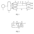
- FIG. 1 an electric wire bundle is shown which comprises schematically shown wires 10, 10' ... 10 n , each wire being connected to a load 11, 11' ... 11 n . All wires are coupled with a power supply 1 through a bus bar 2 which controls feeding of electric current to each of the wires 10, 10' ... 10 n in well-known manner.
- 12 ... 12 n is provided in each wire.
- a switch 15 in the protective device as indicated in Fig. 2 opens to interrupt current flow to the associated load 11 when current causing a critical temperature threshold value is determined.
- the protection unit 12 comprises a computation unit 16, a thermal memory 17 and a table 18.
- the thermal memory 17 is shown as a separate device. However it is conceivable that the thermal memory is part of the computation unit 16.
- all protective devices 12, 12' ... 12 n are identical in structure and function.
- the thermal memory 17 stores information on the present current flow and the more recent current flow from which information the computation unit 16 determines the temperature in wire 10, which would exist if wire 10 were a separate wire not incorporated in a wire bundle.
- table 18 information on heat development by current flow of all other individual wires 10, 10' ... 10 n , of heat conductivity of these wires and of the heat transmission coefficients between the individual wires of the wire bundle is stored.
- Such a table is generated in an empiric way and the table 18 may in the form of or part of a memory element. It can also be included in the computation unit 16.
- all protective devices 12, 12', ... 12 n are coupled for data exchange with any two protective devices mutually coupled.
- the information on current flow through each wire 10, 10', ... 10 n is transmitted to each protective device 12, 12', ... 12 n and in each protective device the information on current flows obtained is evaluated by the computation unit 16 by means of the information contained in the table 18, i. e. by taking into consideration the influence of all wires of the wire bundle on an individual wire, e. g. wire 10.
- the virtual current flow obtained thereby represents the current flow which causes the non-measurable actual temperature of the wire, and is then compared to a threshold current value.
- the protective device 12 interrupts connection of the load 11 with the power supply 1 by opening the switch 15 when such virtual current exceeds the threshold value.
- the system may switch off a wire which causes considerable heating of a wire in which the virtual current flow exceeded the threshold value rather than switching off the latter wire itself.
- Fig. 3 a system is schematically shown, and identical or corresponding elements of Fig. 1 are designated with reference numerals increased by 100 compared to Fig. 1 . Those elements of Fig. 3 not described in the following are identical in function and structure to those described with respect to Fig. 1 .
- the system of Fig. 3 comprises a central unit 120 containing a computation unit, thermal memories for each of the wires 110, 110', ... 110 n as well as tables corresponding to table 18 of Fig. 2 for each of the wires 110, 110', ... 110 n .
- Each of the protective units 112, 112', ... 112 n comprises a switch corresponding to switch 15 in Fig. 2 which is controlled by the cen-tral unit 120.
- the information on current flows through the protective devices 112, 112', ... 112 n is transmitted to the central unit 120, and in the central unit such information is evaluated similar to the way described with respect to Figs. 1 and 2 to obtain information on the actual temperature in each wire 110, 110', ...
Landscapes
- Physics & Mathematics (AREA)
- General Physics & Mathematics (AREA)
- Emergency Protection Circuit Devices (AREA)
- Electric Cable Installation (AREA)
Abstract
Description
- The present invention relates to a method and a system for monitoring temperature of each of the electric wires in a wire bundle coupled with a power supply.
- Wire bundles comprising individual electric wires with one end thereof coupled with a power supply and with the other end coupled with a load are used in numerous fields like stationary machines, automobiles, ships and aircraft. In many cases the individual wires are protected against electric overload by fuses or mechanical circuit breakers which either melt or open a connector upon overheating. In modern aircraft it is also known to use electronic protective devices which measure the current flow in the individual wire and which calculate the temperature generated in the wire by such current flow, taking into consideration heating by prior current flows by means of a so-called thermal memory. When a predetermined temperature is exceeded, the protective device causes switching off of the load connected to the wire.
- As in these prior systems the temperature is determined on the basis of a wire which is not incorporated in a wire bundle and as the temperature in a wire incorporated in a wire bundle may be higher than such "out-of-bundle" temperature, it is necessary to provide for over dimensioning of the wire to ensure that a non-detected increase of temperature in the wire e.g. due to heat transfer from the wires of the wire bundle does not cause any damage.
- It is an object of the invention to permit a more accurate determination of the actual temperature in an electric wire of a wire bundle.
- For solving such an object the invention provides for a method for monitoring temperature of each of the electric wires in a wire bundle coupled with a power supply, wherein each wire is coupled with a load or a cluster of loads and wherein between the power supply and each load an electronic protective device is provided and wherein at least the electric current for each wire is compared with a predetermined threshold value and deactivation of a load is effected when such threshold value is exceeded. Such a method provides determining of the current flows in all wires of the wire bundle and combining the values obtained for obtaining a virtual current flow in the respective wire of the wire bundle, wherein upon exceeding said threshold value by the virtual current flow at least one load is deactivated. Preferably all protective devices are associated with a thermal memory so that heat remaining in the individual wire due to recent current flow can be taken into consideration
- To take into consideration the influence of all wires of the wire bundle on an individual wire, the information on current flows in all wires are combined to obtain a corresponding virtual current flow which corresponds to the temperature caused by both the actual current flow in such wire and the increase in temperature caused by all other wires of the wire bundle. Preferably the remaining heat in the wires caused by recent current flows is also taken into consideration. When the virtual current flow determined exceeds the threshold value, at least one load will be deactivated. Thereby the system operates with highly increased safety, since switching off of the corresponding load is effected dependent on the actual temperature of the wire within the wire bundle without requiring over dimensioning for compensating for the unknown temperature difference between the temperature caused by a current flow in an "out-of-bundle" wire and the actual temperature generated by such a current flow in a wire forming part of an electric wire bundle. In addition avoiding over dimensioning of the wires reduces the weight of the bundle which weight reduction is particularly advantageous in connection with aircraft.
- In most cases the load connected to the wire in which exceeding of the virtual current flow has been detected, will be switched off. However, in certain cases it is also possible to reduce the actual temperature in such a wire by switching off a load connected to a wire which causes considerable heating of the wire bundle, in particular when operation of such a load is not absolutely necessary at this time.
- In a preferred embodiment of the invention a table is associated with each protective device for determining said virtual current flow. Such a table can be produced by empirical methods and may contain information about the bundle size, the current on the other wires, the type of wiring/wire gauge, heat development by current flow in the individual wires of the wire bundle, heat conductivity of the individual wires of the wire bundle, and the heat transmission coefficients between the individual wires of the wire bundle.
- In one embodiment each protective element may comprise such a table stored in a memory element and determine the corresponding virtual current flow obtained by exchanging the data about the current flows between the protective devices.
- In another embodiment the tables may be provided in a central unit, and the current flow data of all wires are evaluated in the central unit. The data of virtual current flows are then used to control the corresponding protective devices.
- In a system according to the invention for monitoring temperature of each of the electric wires in a wire bundle coupled with a power supply each wire is coupled with a load and between the power supply and each load an electronic protective device is provided wherein at least the electric current for each wire is compared with a predetermined threshold value and deactivation of a load is effected when such threshold value is exceeded.
- In one embodiment the protective devices are coupled directly or indirectly for data exchange.
- Coupling of the protective devices may be effected by mutually coupling any two protective devices.
- In such a system each protective device may comprise a table in a memory element containing information on the bundle size and the type of wiring/wire gauge, heat generation by current flow in each of the wires of the wire bundle, on heat conductivity of the individual wires and heat transfer coefficients between the individual wires.
- In another embodiment all protective devices are coupled for data transfer with a central unit which central unit comprises a table for each of the wires of the wire bundle, which table contains information on the heat development by current flow in each individual wire of the wire bundle, heat conductivity of the individual wires and heat transfer coefficients between the individual wires of the wire bundle. The central unit further comprises a computation unit for determining the virtual current flows for all protective devices.
- In each system each protective device may be associated with a thermal memory for storing information on the recent current flow in the wire to permit taking into consideration remaining heat in the wire.
- In the following the invention will be described in more detail with respect to the embodiments shown in the Figures.
- Fig. 1
- shows in a schematic block diagram a system according to the invention.
- Fig. 2
- shows in a schematic block diagram elements provided in the protective devices of the system according to
Fig. 1 . - Fig. 3
- shows in a schematic block diagram another embodiment of the invention.
- In
Fig. 1 an electric wire bundle is shown which comprises schematically shownwires 10, 10' ... 10n, each wire being connected to aload 11, 11' ... 11n. All wires are coupled with a power supply 1 through abus bar 2 which controls feeding of electric current to each of thewires 10, 10' ... 10n in well-known manner. For protecting each of thewires 10, 10' ... 10n against overheating an electronicprotective device switch 15 in the protective device as indicated inFig. 2 opens to interrupt current flow to the associatedload 11 when current causing a critical temperature threshold value is determined. - As indicated in
Fig. 2 , theprotection unit 12 comprises acomputation unit 16, athermal memory 17 and a table 18. In this preferred embodiment, thethermal memory 17 is shown as a separate device. However it is conceivable that the thermal memory is part of thecomputation unit 16. In this connection it should be noted that allprotective devices 12, 12' ... 12n are identical in structure and function. - The
thermal memory 17 stores information on the present current flow and the more recent current flow from which information thecomputation unit 16 determines the temperature inwire 10, which would exist ifwire 10 were a separate wire not incorporated in a wire bundle. In this embodiment in table 18 information on heat development by current flow of all otherindividual wires 10, 10' ... 10n, of heat conductivity of these wires and of the heat transmission coefficients between the individual wires of the wire bundle is stored. Such a table is generated in an empiric way and the table 18 may in the form of or part of a memory element. It can also be included in thecomputation unit 16. - As indicated in
Fig. 1 , allprotective devices 12, 12', ... 12n are coupled for data exchange with any two protective devices mutually coupled. Thereby the information on current flow through eachwire 10, 10', ... 10n is transmitted to eachprotective device 12, 12', ... 12n and in each protective device the information on current flows obtained is evaluated by thecomputation unit 16 by means of the information contained in the table 18, i. e. by taking into consideration the influence of all wires of the wire bundle on an individual wire,e. g. wire 10. The virtual current flow obtained thereby represents the current flow which causes the non-measurable actual temperature of the wire, and is then compared to a threshold current value. Theprotective device 12 interrupts connection of theload 11 with the power supply 1 by opening theswitch 15 when such virtual current exceeds the threshold value. - As in such system information on the heating influence of all wires of the wire bundle on each individual wire is available, the system may switch off a wire which causes considerable heating of a wire in which the virtual current flow exceeded the threshold value rather than switching off the latter wire itself.
- In the embodiment of
Fig. 3 a system is schematically shown, and identical or corresponding elements ofFig. 1 are designated with reference numerals increased by 100 compared toFig. 1 . Those elements ofFig. 3 not described in the following are identical in function and structure to those described with respect toFig. 1 . - The system of
Fig. 3 comprises acentral unit 120 containing a computation unit, thermal memories for each of thewires 110, 110', ... 110n as well as tables corresponding to table 18 ofFig. 2 for each of thewires 110, 110', ... 110n. Each of theprotective units 112, 112', ... 112n comprises a switch corresponding toswitch 15 inFig. 2 which is controlled by the cen-tral unit 120. The information on current flows through theprotective devices 112, 112', ... 112n is transmitted to thecentral unit 120, and in the central unit such information is evaluated similar to the way described with respect toFigs. 1 and 2 to obtain information on the actual temperature in eachwire 110, 110', ... 110n in form of a virtual current flow. These virtual flows are compared to corresponding threshold values stored in thecentral unit 120 and the central unit opens the switch in one or more protective units when at least one threshold value is exceeded, as described in connection withFigs. 1 and 2 .
Claims (12)
- A method for monitoring temperature of each of the electric wires in a wire bundle coupled with a power supply, wherein each wire is coupled with a load and wherein between the power supply and each load an electronic protective device is provided and wherein at least the electric current in each wire is compared with a predetermined threshold value and deactivation of a load is effected when such threshold value is exceeded, characterized in that the current flows in all wires of the wire bundle are determined and the values obtained are combined for obtaining a virtual current flow in the respective wire of the wire bundle and that upon exceeding said threshold value by the virtual current flow at least one load is deactivated.
- A method according to claim 1, characterized in that the load connected to the wire exceeding said threshold value is deactivated.
- A method according to claim 1 or 2, characterized in that each protective device is associated with a memory storing information on the recent current flow in the wire to permit taking into consideration remaining heat in the wire.
- A method according to one of claims 1 to 3, characterized in that for obtaining a virtual current flow each protective device is associated with a table containing information such as the bundle size, the current on the other wires, the type of wiring/wire gauge, heat development by current flow in the individual wires of the wire bundle, heat conductivity of the individual wires of the wire bundle, and the heat transmission coefficients between the individual wires of the wire bundle.
- A method according to claim 4, characterized in that each protective device comprises a table and that determining of the individual virtual current flow is obtained by exchanging current flow data between the protective devices.
- A method according to claim 4, characterized in that said tables are provided within a central unit and that the current flow data of all wires are evaluated within such central unit and that the data of the virtual current flows obtained are used for controlling the associated protective devices.
- A system for monitoring temperature of each of the electric wires (10, 10' ... 10n) in a wire bundle coupled with a power supply (1), wherein each wire is coupled with a load (11, 11' ... 11n) and wherein between the power supply and each load an electronic protective device (12, 12' ... 12n) is provided and wherein at least the electric current in each wire (10, 10' ... 10n) is compared with a predetermined threshold value and deactivation of a load (11, 11' ... 11n) is effected when such threshold value is exceeded, characterized in that the protective devices (12, 12' ... 12n) are all directly or indirectly coupled for data exchange.
- A system according to claim 7, characterized in that each protective device (12, 12' ... 12n) comprises a memory (17) for storing information on the recent current flow in the wire (10, 10' ... 10n) to permit taking into consideration remaining heat in such wire.
- A system according to claim 7 or 8, characterized in that each protective device (12, 12' ... 12n) comprises a table (18) containing information about development of heat by current flow in the individual wires of the wire bundle, heat conductivity of the individual wires and the heat exchange coefficients between the individual wires of the wire bundle.
- A system according one of claims 7 to 9, characterized in that all protective devices (12, 12' ... 12n) are mutually coupled for data exchange.
- A system for monitoring temperature of each of the electric wires (110, 110' ... 110n) in a wire bundle coupled with a power supply (101), wherein each wire is coupled with a load (111, 111' ... 111n) and wherein between the power supply and each load an electronic protective device (112, 112' ... 112n) is provided and wherein at least the electric current in each wire (110, 110' ... 110n) is compared with a predetermined threshold value and deactivation of a load is effected when such threshold value is exceeded, characterized in that all protective devices (112, 112' ... 112n) are coupled with a central unit (120) for data transfer which central unit comprises a table for each protective device with information about heat development by current flow in the individual wires of the wire bundle, heat conductivity of said wires and the heat transfer coefficients between the individual wires of the wire bundle, and that said central unit (120) comprises a computation unit for determining the virtual current flows for all protective devices (112, 112' ... 112n).
- A system according to claim 11, characterized in that the central unit (120) comprises a memory for storing information on the recent current flow in each of the wires to permit taking into consideration remaining heat in such wires.
Priority Applications (1)
| Application Number | Priority Date | Filing Date | Title |
|---|---|---|---|
| EP14174697.4A EP2960636B1 (en) | 2014-06-27 | 2014-06-27 | A method and a system for monitoring temperatures of electric wires within a wire bundle |
Applications Claiming Priority (1)
| Application Number | Priority Date | Filing Date | Title |
|---|---|---|---|
| EP14174697.4A EP2960636B1 (en) | 2014-06-27 | 2014-06-27 | A method and a system for monitoring temperatures of electric wires within a wire bundle |
Publications (2)
| Publication Number | Publication Date |
|---|---|
| EP2960636A1 true EP2960636A1 (en) | 2015-12-30 |
| EP2960636B1 EP2960636B1 (en) | 2017-10-11 |
Family
ID=51022243
Family Applications (1)
| Application Number | Title | Priority Date | Filing Date |
|---|---|---|---|
| EP14174697.4A Active EP2960636B1 (en) | 2014-06-27 | 2014-06-27 | A method and a system for monitoring temperatures of electric wires within a wire bundle |
Country Status (1)
| Country | Link |
|---|---|
| EP (1) | EP2960636B1 (en) |
Citations (2)
| Publication number | Priority date | Publication date | Assignee | Title |
|---|---|---|---|---|
| JPH10285784A (en) * | 1997-04-04 | 1998-10-23 | Yazaki Corp | Power supply for vehicle |
| DE10257425A1 (en) * | 2002-12-09 | 2004-06-24 | Delphi Technologies, Inc., Troy | Electrical voltage supply monitoring arrangement for protecting a system against overloading, e.g. in a motor vehicle, whereby thermodynamic models of cables or components are used to predict over-heating |
-
2014
- 2014-06-27 EP EP14174697.4A patent/EP2960636B1/en active Active
Patent Citations (2)
| Publication number | Priority date | Publication date | Assignee | Title |
|---|---|---|---|---|
| JPH10285784A (en) * | 1997-04-04 | 1998-10-23 | Yazaki Corp | Power supply for vehicle |
| DE10257425A1 (en) * | 2002-12-09 | 2004-06-24 | Delphi Technologies, Inc., Troy | Electrical voltage supply monitoring arrangement for protecting a system against overloading, e.g. in a motor vehicle, whereby thermodynamic models of cables or components are used to predict over-heating |
Non-Patent Citations (2)
| Title |
|---|
| BLACK W Z ET AL: "Ampacity of Diversely Loaded Cables in Covered and Uncovered Trays", IEEE TRANSACTIONS ON POWER DELIVERY, IEEE SERVICE CENTER, NEW YORK, NY, US, vol. 15, no. 1, 1 January 2000 (2000-01-01), XP011049741, ISSN: 0885-8977 * |
| FLORIAN LOOS ET AL: "Two approaches for heat transfer simulation of current carrying multicables", MATHEMATICS AND COMPUTERS IN SIMULATION, vol. 101, 19 March 2014 (2014-03-19), pages 13 - 30, XP055144059, ISSN: 0378-4754, DOI: 10.1016/j.matcom.2014.01.008 * |
Also Published As
| Publication number | Publication date |
|---|---|
| EP2960636B1 (en) | 2017-10-11 |
Similar Documents
| Publication | Publication Date | Title |
|---|---|---|
| EP3747702B1 (en) | Method of power supply line protection, master device, and power supply system | |
| EP3487024B1 (en) | Power dissipation monitoring and load management | |
| JP5055177B2 (en) | Load circuit protection device | |
| US10871807B2 (en) | Power distribution system with thermal cutoff for dielectric cooling systems | |
| EP1657796A1 (en) | Method and system for thermal management | |
| US8852045B2 (en) | Electric oil pump system and control method thereof | |
| CN104332954A (en) | Circuit for Thermal Protection and Power Regulation of Electric Motors | |
| CN105359245A (en) | Electronic protection circuit and method of controlling the same | |
| CN105594095A (en) | Remote protection and switching device for electrical systems | |
| US10126715B2 (en) | Controller having CPU abnormality detection function | |
| CN102082044A (en) | Circuit breaker control | |
| US8996189B2 (en) | Method and device for optimized energy management | |
| US20130160522A1 (en) | Battery Test and Condensation Prevention Method, System and Apparatus | |
| CN106257808A (en) | Electric component | |
| EP2960636B1 (en) | A method and a system for monitoring temperatures of electric wires within a wire bundle | |
| JP5583155B2 (en) | Electric wire protection device for vehicles | |
| CA3029292C (en) | Circuit interruption device with thermal protection | |
| JP6136900B2 (en) | Temperature calculation device and protection device | |
| CN104192080B (en) | Circuit management system and method of vehicle | |
| CN103175632A (en) | Real-time temperature calculation method and protective device for electrical equipment | |
| CN117697240A (en) | Electric welding machine temperature protection circuit and electric welding machine | |
| JP7743269B2 (en) | Vehicle control device | |
| CN213716700U (en) | Transformer assembly with temperature protection function and power system | |
| CN119439837A (en) | Smart power safety management control cabinet | |
| US9019676B2 (en) | System and method for protecting an appliance junction |
Legal Events
| Date | Code | Title | Description |
|---|---|---|---|
| PUAI | Public reference made under article 153(3) epc to a published international application that has entered the european phase |
Free format text: ORIGINAL CODE: 0009012 |
|
| AK | Designated contracting states |
Kind code of ref document: A1 Designated state(s): AL AT BE BG CH CY CZ DE DK EE ES FI FR GB GR HR HU IE IS IT LI LT LU LV MC MK MT NL NO PL PT RO RS SE SI SK SM TR |
|
| AX | Request for extension of the european patent |
Extension state: BA ME |
|
| 17P | Request for examination filed |
Effective date: 20160630 |
|
| RBV | Designated contracting states (corrected) |
Designated state(s): AL AT BE BG CH CY CZ DE DK EE ES FI FR GB GR HR HU IE IS IT LI LT LU LV MC MK MT NL NO PL PT RO RS SE SI SK SM TR |
|
| GRAP | Despatch of communication of intention to grant a patent |
Free format text: ORIGINAL CODE: EPIDOSNIGR1 |
|
| INTG | Intention to grant announced |
Effective date: 20170412 |
|
| GRAS | Grant fee paid |
Free format text: ORIGINAL CODE: EPIDOSNIGR3 |
|
| GRAA | (expected) grant |
Free format text: ORIGINAL CODE: 0009210 |
|
| AK | Designated contracting states |
Kind code of ref document: B1 Designated state(s): AL AT BE BG CH CY CZ DE DK EE ES FI FR GB GR HR HU IE IS IT LI LT LU LV MC MK MT NL NO PL PT RO RS SE SI SK SM TR |
|
| REG | Reference to a national code |
Ref country code: GB Ref legal event code: FG4D |
|
| REG | Reference to a national code |
Ref country code: CH Ref legal event code: EP |
|
| REG | Reference to a national code |
Ref country code: IE Ref legal event code: FG4D |
|
| REG | Reference to a national code |
Ref country code: AT Ref legal event code: REF Ref document number: 936463 Country of ref document: AT Kind code of ref document: T Effective date: 20171115 |
|
| REG | Reference to a national code |
Ref country code: DE Ref legal event code: R096 Ref document number: 602014015595 Country of ref document: DE |
|
| REG | Reference to a national code |
Ref country code: NL Ref legal event code: MP Effective date: 20171011 |
|
| REG | Reference to a national code |
Ref country code: LT Ref legal event code: MG4D |
|
| REG | Reference to a national code |
Ref country code: AT Ref legal event code: MK05 Ref document number: 936463 Country of ref document: AT Kind code of ref document: T Effective date: 20171011 |
|
| PG25 | Lapsed in a contracting state [announced via postgrant information from national office to epo] |
Ref country code: NL Free format text: LAPSE BECAUSE OF FAILURE TO SUBMIT A TRANSLATION OF THE DESCRIPTION OR TO PAY THE FEE WITHIN THE PRESCRIBED TIME-LIMIT Effective date: 20171011 |
|
| PG25 | Lapsed in a contracting state [announced via postgrant information from national office to epo] |
Ref country code: NO Free format text: LAPSE BECAUSE OF FAILURE TO SUBMIT A TRANSLATION OF THE DESCRIPTION OR TO PAY THE FEE WITHIN THE PRESCRIBED TIME-LIMIT Effective date: 20180111 Ref country code: FI Free format text: LAPSE BECAUSE OF FAILURE TO SUBMIT A TRANSLATION OF THE DESCRIPTION OR TO PAY THE FEE WITHIN THE PRESCRIBED TIME-LIMIT Effective date: 20171011 Ref country code: ES Free format text: LAPSE BECAUSE OF FAILURE TO SUBMIT A TRANSLATION OF THE DESCRIPTION OR TO PAY THE FEE WITHIN THE PRESCRIBED TIME-LIMIT Effective date: 20171011 Ref country code: SE Free format text: LAPSE BECAUSE OF FAILURE TO SUBMIT A TRANSLATION OF THE DESCRIPTION OR TO PAY THE FEE WITHIN THE PRESCRIBED TIME-LIMIT Effective date: 20171011 Ref country code: LT Free format text: LAPSE BECAUSE OF FAILURE TO SUBMIT A TRANSLATION OF THE DESCRIPTION OR TO PAY THE FEE WITHIN THE PRESCRIBED TIME-LIMIT Effective date: 20171011 |
|
| PG25 | Lapsed in a contracting state [announced via postgrant information from national office to epo] |
Ref country code: IS Free format text: LAPSE BECAUSE OF FAILURE TO SUBMIT A TRANSLATION OF THE DESCRIPTION OR TO PAY THE FEE WITHIN THE PRESCRIBED TIME-LIMIT Effective date: 20180211 Ref country code: GR Free format text: LAPSE BECAUSE OF FAILURE TO SUBMIT A TRANSLATION OF THE DESCRIPTION OR TO PAY THE FEE WITHIN THE PRESCRIBED TIME-LIMIT Effective date: 20180112 Ref country code: LV Free format text: LAPSE BECAUSE OF FAILURE TO SUBMIT A TRANSLATION OF THE DESCRIPTION OR TO PAY THE FEE WITHIN THE PRESCRIBED TIME-LIMIT Effective date: 20171011 Ref country code: AT Free format text: LAPSE BECAUSE OF FAILURE TO SUBMIT A TRANSLATION OF THE DESCRIPTION OR TO PAY THE FEE WITHIN THE PRESCRIBED TIME-LIMIT Effective date: 20171011 Ref country code: HR Free format text: LAPSE BECAUSE OF FAILURE TO SUBMIT A TRANSLATION OF THE DESCRIPTION OR TO PAY THE FEE WITHIN THE PRESCRIBED TIME-LIMIT Effective date: 20171011 Ref country code: BG Free format text: LAPSE BECAUSE OF FAILURE TO SUBMIT A TRANSLATION OF THE DESCRIPTION OR TO PAY THE FEE WITHIN THE PRESCRIBED TIME-LIMIT Effective date: 20180111 Ref country code: RS Free format text: LAPSE BECAUSE OF FAILURE TO SUBMIT A TRANSLATION OF THE DESCRIPTION OR TO PAY THE FEE WITHIN THE PRESCRIBED TIME-LIMIT Effective date: 20171011 |
|
| REG | Reference to a national code |
Ref country code: FR Ref legal event code: PLFP Year of fee payment: 5 |
|
| REG | Reference to a national code |
Ref country code: DE Ref legal event code: R097 Ref document number: 602014015595 Country of ref document: DE |
|
| PG25 | Lapsed in a contracting state [announced via postgrant information from national office to epo] |
Ref country code: DK Free format text: LAPSE BECAUSE OF FAILURE TO SUBMIT A TRANSLATION OF THE DESCRIPTION OR TO PAY THE FEE WITHIN THE PRESCRIBED TIME-LIMIT Effective date: 20171011 Ref country code: SK Free format text: LAPSE BECAUSE OF FAILURE TO SUBMIT A TRANSLATION OF THE DESCRIPTION OR TO PAY THE FEE WITHIN THE PRESCRIBED TIME-LIMIT Effective date: 20171011 Ref country code: EE Free format text: LAPSE BECAUSE OF FAILURE TO SUBMIT A TRANSLATION OF THE DESCRIPTION OR TO PAY THE FEE WITHIN THE PRESCRIBED TIME-LIMIT Effective date: 20171011 Ref country code: CZ Free format text: LAPSE BECAUSE OF FAILURE TO SUBMIT A TRANSLATION OF THE DESCRIPTION OR TO PAY THE FEE WITHIN THE PRESCRIBED TIME-LIMIT Effective date: 20171011 |
|
| PLBE | No opposition filed within time limit |
Free format text: ORIGINAL CODE: 0009261 |
|
| STAA | Information on the status of an ep patent application or granted ep patent |
Free format text: STATUS: NO OPPOSITION FILED WITHIN TIME LIMIT |
|
| PG25 | Lapsed in a contracting state [announced via postgrant information from national office to epo] |
Ref country code: SM Free format text: LAPSE BECAUSE OF FAILURE TO SUBMIT A TRANSLATION OF THE DESCRIPTION OR TO PAY THE FEE WITHIN THE PRESCRIBED TIME-LIMIT Effective date: 20171011 Ref country code: PL Free format text: LAPSE BECAUSE OF FAILURE TO SUBMIT A TRANSLATION OF THE DESCRIPTION OR TO PAY THE FEE WITHIN THE PRESCRIBED TIME-LIMIT Effective date: 20171011 Ref country code: IT Free format text: LAPSE BECAUSE OF FAILURE TO SUBMIT A TRANSLATION OF THE DESCRIPTION OR TO PAY THE FEE WITHIN THE PRESCRIBED TIME-LIMIT Effective date: 20171011 Ref country code: RO Free format text: LAPSE BECAUSE OF FAILURE TO SUBMIT A TRANSLATION OF THE DESCRIPTION OR TO PAY THE FEE WITHIN THE PRESCRIBED TIME-LIMIT Effective date: 20171011 |
|
| 26N | No opposition filed |
Effective date: 20180712 |
|
| PG25 | Lapsed in a contracting state [announced via postgrant information from national office to epo] |
Ref country code: SI Free format text: LAPSE BECAUSE OF FAILURE TO SUBMIT A TRANSLATION OF THE DESCRIPTION OR TO PAY THE FEE WITHIN THE PRESCRIBED TIME-LIMIT Effective date: 20171011 |
|
| REG | Reference to a national code |
Ref country code: CH Ref legal event code: PL |
|
| REG | Reference to a national code |
Ref country code: BE Ref legal event code: MM Effective date: 20180630 |
|
| PG25 | Lapsed in a contracting state [announced via postgrant information from national office to epo] |
Ref country code: MC Free format text: LAPSE BECAUSE OF FAILURE TO SUBMIT A TRANSLATION OF THE DESCRIPTION OR TO PAY THE FEE WITHIN THE PRESCRIBED TIME-LIMIT Effective date: 20171011 Ref country code: LU Free format text: LAPSE BECAUSE OF NON-PAYMENT OF DUE FEES Effective date: 20180627 |
|
| REG | Reference to a national code |
Ref country code: IE Ref legal event code: MM4A |
|
| PG25 | Lapsed in a contracting state [announced via postgrant information from national office to epo] |
Ref country code: CH Free format text: LAPSE BECAUSE OF NON-PAYMENT OF DUE FEES Effective date: 20180630 Ref country code: IE Free format text: LAPSE BECAUSE OF NON-PAYMENT OF DUE FEES Effective date: 20180627 Ref country code: LI Free format text: LAPSE BECAUSE OF NON-PAYMENT OF DUE FEES Effective date: 20180630 |
|
| PG25 | Lapsed in a contracting state [announced via postgrant information from national office to epo] |
Ref country code: BE Free format text: LAPSE BECAUSE OF NON-PAYMENT OF DUE FEES Effective date: 20180630 |
|
| PG25 | Lapsed in a contracting state [announced via postgrant information from national office to epo] |
Ref country code: MT Free format text: LAPSE BECAUSE OF NON-PAYMENT OF DUE FEES Effective date: 20180627 |
|
| PG25 | Lapsed in a contracting state [announced via postgrant information from national office to epo] |
Ref country code: TR Free format text: LAPSE BECAUSE OF FAILURE TO SUBMIT A TRANSLATION OF THE DESCRIPTION OR TO PAY THE FEE WITHIN THE PRESCRIBED TIME-LIMIT Effective date: 20171011 |
|
| PG25 | Lapsed in a contracting state [announced via postgrant information from national office to epo] |
Ref country code: PT Free format text: LAPSE BECAUSE OF FAILURE TO SUBMIT A TRANSLATION OF THE DESCRIPTION OR TO PAY THE FEE WITHIN THE PRESCRIBED TIME-LIMIT Effective date: 20171011 |
|
| PG25 | Lapsed in a contracting state [announced via postgrant information from national office to epo] |
Ref country code: CY Free format text: LAPSE BECAUSE OF FAILURE TO SUBMIT A TRANSLATION OF THE DESCRIPTION OR TO PAY THE FEE WITHIN THE PRESCRIBED TIME-LIMIT Effective date: 20171011 Ref country code: HU Free format text: LAPSE BECAUSE OF FAILURE TO SUBMIT A TRANSLATION OF THE DESCRIPTION OR TO PAY THE FEE WITHIN THE PRESCRIBED TIME-LIMIT; INVALID AB INITIO Effective date: 20140627 Ref country code: MK Free format text: LAPSE BECAUSE OF NON-PAYMENT OF DUE FEES Effective date: 20171011 |
|
| PG25 | Lapsed in a contracting state [announced via postgrant information from national office to epo] |
Ref country code: AL Free format text: LAPSE BECAUSE OF FAILURE TO SUBMIT A TRANSLATION OF THE DESCRIPTION OR TO PAY THE FEE WITHIN THE PRESCRIBED TIME-LIMIT Effective date: 20171011 |
|
| PGFP | Annual fee paid to national office [announced via postgrant information from national office to epo] |
Ref country code: DE Payment date: 20250618 Year of fee payment: 12 |
|
| PGFP | Annual fee paid to national office [announced via postgrant information from national office to epo] |
Ref country code: GB Payment date: 20250618 Year of fee payment: 12 |
|
| PGFP | Annual fee paid to national office [announced via postgrant information from national office to epo] |
Ref country code: FR Payment date: 20250625 Year of fee payment: 12 |